EP2905605A1 - Apparatus for measuring light scattering - Google Patents
Apparatus for measuring light scattering Download PDFInfo
- Publication number
- EP2905605A1 EP2905605A1 EP14382043.9A EP14382043A EP2905605A1 EP 2905605 A1 EP2905605 A1 EP 2905605A1 EP 14382043 A EP14382043 A EP 14382043A EP 2905605 A1 EP2905605 A1 EP 2905605A1
- Authority
- EP
- European Patent Office
- Prior art keywords
- sample
- power
- sensor
- filter
- light
- Prior art date
- Legal status (The legal status is an assumption and is not a legal conclusion. Google has not performed a legal analysis and makes no representation as to the accuracy of the status listed.)
- Granted
Links
Images







Classifications
-
- G—PHYSICS
- G01—MEASURING; TESTING
- G01N—INVESTIGATING OR ANALYSING MATERIALS BY DETERMINING THEIR CHEMICAL OR PHYSICAL PROPERTIES
- G01N21/00—Investigating or analysing materials by the use of optical means, i.e. using sub-millimetre waves, infrared, visible or ultraviolet light
- G01N21/17—Systems in which incident light is modified in accordance with the properties of the material investigated
- G01N21/47—Scattering, i.e. diffuse reflection
-
- G—PHYSICS
- G01—MEASURING; TESTING
- G01N—INVESTIGATING OR ANALYSING MATERIALS BY DETERMINING THEIR CHEMICAL OR PHYSICAL PROPERTIES
- G01N21/00—Investigating or analysing materials by the use of optical means, i.e. using sub-millimetre waves, infrared, visible or ultraviolet light
- G01N21/17—Systems in which incident light is modified in accordance with the properties of the material investigated
- G01N21/55—Specular reflectivity
- G01N21/57—Measuring gloss
-
- G—PHYSICS
- G01—MEASURING; TESTING
- G01N—INVESTIGATING OR ANALYSING MATERIALS BY DETERMINING THEIR CHEMICAL OR PHYSICAL PROPERTIES
- G01N21/00—Investigating or analysing materials by the use of optical means, i.e. using sub-millimetre waves, infrared, visible or ultraviolet light
- G01N21/17—Systems in which incident light is modified in accordance with the properties of the material investigated
- G01N21/55—Specular reflectivity
- G01N2021/555—Measuring total reflection power, i.e. scattering and specular
-
- G—PHYSICS
- G01—MEASURING; TESTING
- G01N—INVESTIGATING OR ANALYSING MATERIALS BY DETERMINING THEIR CHEMICAL OR PHYSICAL PROPERTIES
- G01N21/00—Investigating or analysing materials by the use of optical means, i.e. using sub-millimetre waves, infrared, visible or ultraviolet light
- G01N21/17—Systems in which incident light is modified in accordance with the properties of the material investigated
- G01N21/55—Specular reflectivity
- G01N2021/556—Measuring separately scattering and specular
-
- G—PHYSICS
- G01—MEASURING; TESTING
- G01N—INVESTIGATING OR ANALYSING MATERIALS BY DETERMINING THEIR CHEMICAL OR PHYSICAL PROPERTIES
- G01N21/00—Investigating or analysing materials by the use of optical means, i.e. using sub-millimetre waves, infrared, visible or ultraviolet light
- G01N21/17—Systems in which incident light is modified in accordance with the properties of the material investigated
- G01N21/47—Scattering, i.e. diffuse reflection
- G01N21/4738—Diffuse reflection, e.g. also for testing fluids, fibrous materials
-
- G—PHYSICS
- G01—MEASURING; TESTING
- G01N—INVESTIGATING OR ANALYSING MATERIALS BY DETERMINING THEIR CHEMICAL OR PHYSICAL PROPERTIES
- G01N21/00—Investigating or analysing materials by the use of optical means, i.e. using sub-millimetre waves, infrared, visible or ultraviolet light
- G01N21/17—Systems in which incident light is modified in accordance with the properties of the material investigated
- G01N21/47—Scattering, i.e. diffuse reflection
- G01N21/49—Scattering, i.e. diffuse reflection within a body or fluid
- G01N21/53—Scattering, i.e. diffuse reflection within a body or fluid within a flowing fluid, e.g. smoke
- G01N21/534—Scattering, i.e. diffuse reflection within a body or fluid within a flowing fluid, e.g. smoke by measuring transmission alone, i.e. determining opacity
-
- G—PHYSICS
- G01—MEASURING; TESTING
- G01N—INVESTIGATING OR ANALYSING MATERIALS BY DETERMINING THEIR CHEMICAL OR PHYSICAL PROPERTIES
- G01N2201/00—Features of devices classified in G01N21/00
- G01N2201/04—Batch operation; multisample devices
- G01N2201/0407—Batch operation; multisample devices with multiple optical units, e.g. one per sample
Definitions
- the present invention relates to an apparatus for measuring light scattering, haze and other related properties produced by non uniform liquid, solid or gas samples, both in their bulk or surface state.
- Turbidity is a monitoring parameter used in various fields, such as food industry, water contamination control and water purification plants. Turbidimeters are used, for instance, in wine and beer production, in order to measure the total suspended solids value in a liquid sample. Very often, an inspection image is also needed in order to identify different suspended solids in the sample and their concentrations. Another example could be cheese production in which milk coagulation scattering and clustering effects are off-line monitored.
- Haze, glare and gloss are scattering-related monitoring parameters also used in roll-to-roll plastic sheet, glass or film production. These parameters are usually measured off-line with different devices, of high cost and large dimensions, in order to detect imperfections and inhomogeneities in the samples. After the imperfection is detected, an image usually follows to determine its nature. It is desirable to measure such image using the same apparatus that is used to evaluate the scattering. Haze in a film results in a cloudy appearance or poorer clarity of objects when viewed through the film. This is why haze is a parameter that characterizes transparent and translucent films, not opaque films A Hazemeter measures the haze (light forward scattering) and the light transmitting properties of plastic sheets, film, glass, and liquid products.
- haze is the ratio of the light scattered at an angle larger than 2.5 degree and the total light exiting the sample at any angle.
- Haze measurement is regulated by the standard ASTM D 1003 "Standard Test Methods for Haze and Luminous Transmittance of Transparent Plastics" and ASTM E 167/ASTM E2387 for haze greater than 30%.
- H % 100 * P HA S P T S - P HA R P T R P HA S is the light power corresponding to beams with angles equal or greater than 2.5° emerging from sample. (HA: High Angles) P HA R is the light power corresponding to beams with angles greater than 2.5° emerging from sample holder plane but without any sample placed in. P T S is the total light power emerging from sample. P T R is the total light power emerging from sample holder plane but without any sample placed in.
- a light k vector is defined as a magnitude and direction of a light beam: Its magnitude is either the wavenumber or angular wavenumber of the wave (inversely proportional to the wavelength), and its direction is ordinarily the direction of wave propagation.
- High k vectors are defined as vectors whose direction forms an angle equal or greater than 2.5° with respect to the direction perpendicular to the sample surface under test.
- Low k vectors are defined as those whose direction forms an angle lower than 2.5°.
- the standard haze measurement aims to obtain the power ratio between the high k and the total k vectors emerging from the sample. A final correction with the haze reference is mandatory to reduce, if not eliminate, systematic errors.
- d3 also sets the resolution of this scheme. The smaller the distance the larger the contribution from k vectors further from 2.5 degree angle. In other words, the larger d3 is, the clearer the separation between k vectors. This is a important drawback because, correspondingly, the device requires a minimum size, sometimes this becoming an unpractical feature, especially for in-line measurements.
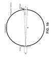
- Commercial hazemeters usually use an integration sphere (see Fig. 1 b) , which is an optical device that concentrates all the k vectors to one point inside it, with an on/off window.
- the collimated light source and an integrating sphere must be placed on opposite sides of the sample and must be structurally interconnected in order to preserve the alignment between source and integrating sphere.
- low k vectors escape from the integration sphere and an optical sensor inside the integration sphere measures only the high k vectors.
- the optical sensor measures the total k vectors.
- distance d3 has been defined as the minimum distance between the sample and the blocking stage in order to separate high from low k vectors.
- ASTM D1003 that is, the needed Integration Sphere diameter
- the invention in its simplest form, includes a light source, a sample holder, at least one light sensor and at least one spatial filter, each filter having two apertures of equal or different diameters for removing the scattered light beams above a predefined angle, that we name cut-off angle.
- an array of spatial filters having different cut-off angles can be used.
- multiple photodetectors or an array of photodetectors, such as complementary metal-oxide-semiconductor (CMOS) or charge-coupled device (CCD) light sensor are preferred.
- CMOS complementary metal-oxide-semiconductor
- CCD charge-coupled device
- one or two photo diodes might be sufficient.
- the sample holder may not be needed, as it is for example for in-line measurements of thin film sheets.
- ⁇ c arctan D 1 + D 2 2 ⁇ L
- ⁇ c the scattering angle
- D1 an D2 the diameters of the apertures
- L the total length of the filter in the direction of the beam.
- a haze value at predefined cut-off angles if the measurement is in transmission from a gel or solid sample a gloss value if the measurement is in reflection from a gel or solid sample, or a turbidity value if the measurement is in transmission from a liquid sample.
- the device can also be used as a turbidimeter if the sample is a liquid one.
- the invention filters and measures the optical power of a representative part of low k vectors (defined as low k power) and a representative part of the total k vectors (defined as a total k power) power by means of at least one filter with two apertures.
- the light source can be of any predetermined wavelength or white, tunable or it can be a light emitting diode. In this way a simplified, portable and compact device for measuring different parameters like haze, turbidity, etc. can be built, for any sample and without the need of changing detectors.
- Figure 3 shows a filter consisting in a conical tube defined by its length and two different apertures in its edges and a filter consisting in two apertures separated a distance L (right).
- the cut-off ⁇ c angle of the k vectors passing through the apertures is defined by the diameters D 1 , D 2 and length L.
- ⁇ c arctan D 1 + D 2 2 ⁇ L
- the filters could be advantageously made of a material (at least the inner walls) with high absorption over the spectrum of the light of the source.
- suitable materials are plastic (preferentially of black color), slate and teflon®.
- the apertures design it may be preferable to use the apertures design in order to avoid possible internal reflection from the inner walls of the cylindrical tube.
- the circular surface area of the spot illuminating the sample with diameter Dc is the field of view (FOV) of the spatial filter at a distance d. Only beamlets (k vectors) coming from points inside the FOV will reach the photodetector.
- the circular surface area of the spot exiting the spatial filter and arriving to the sensor with diameter Dr is the back field of view of the spatial filter at a distance dr.
- the embodiment of Figure 4 shows a collimated beam, with diameter Ds , , illuminating a sample and two separate apertures.
- a diverging beam i.e coming from a hazy sample placed before the filter, passes through the spatial filter.
- the spatial filter has a particular FOV equal to Dc. That means the optical sensor after the spatial filter only "see" Dc surface of the sample. Taking this into account, it is necessary that the input collimated beam has a spot diameter Ds equal or larger than Dc. If Ds were smaller than Dc the sensor would see a non-illuminated part of the sample.
- the spatial filter blocks any k vector with angle higher than a c .
- the light sensor can be placed touching the D2 aperture or at a distance. Its active area, with diameter Dr, has to be equal or larger than the area of the beam spot exiting the spatial filter in order to avoid errors in power light measurement.
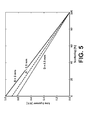
- Figure 5 shows the calculated low k power as a function of scattering for various spatial filter apertures. Scattering here is represented as scattering percentage (the percentage of scattered light power related to total light power). The slope of the curves and the nominal value for a particular scattering, increases with D. That means the invention has better accuracy measuring low k vectors using spatial filters with higher apertures.
- This design condition defines the effective area of the photodiode or of the image sensor, because a sensor area equal or larger than the spatial filter area is needed in order to measure the low k power without errors.
- Figure 6 shows the calculated low k power as a function of the spatial filter aperture for various samples with different scattering percentage.
- Low k power increases with filter diameter but the slope of the curves, and the nominal value for a particular diameter, decrease with scattering. That means for a particular D, the invention has better accuracy measuring low k vectors in samples with lower scattering.
- the preferred conditions to enhance the accuracy of the invention are: a short distance between sample and spatial filter, large diameters of apertures and large area of the photodetector or light sensor.
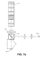
- total power is measured by means of a beam splitter or mirror ( Figure 7a ).
- the total power is measured collecting the whole power of the second beam.
- Figure 7a shows a light source SO, preferably a white light source, such as a light emitting diode LED, with a collimation system for the light source, preferably a Köhler system, illuminating a hazy sample, a beam splitter BS0, preferably with 50/50 split percentages, a lens or lenses to collect the total forward scattered power and a first photodiode to measure it, a spatial filter and a second photodiode to measure the low k power.
- a white light source such as a light emitting diode LED
- a Köhler illumination followed by a collimation lens setup is used.
- a white light source LED illuminates the collimation system and after a 1mm diameter aperture, the homogeneous and collimated beam impinges on the hazy sample.
- a 50/50 beam splitter splits it into two beams. One beam is collected by the photodiode PD 1 which measures a signal proportional to the total power transmitted. The second beam goes through two aligned 1 mm apertures filters and is then measured by the photodiode PD 2 . This measurement is proportional to the low k vectors power.
- the diameters and the separation sets the filter cut-off angle at 2.5°, angle established by the haze standards EPA 180.1 and ISO 7027.
- V PD ⁇ 1 S R 1 ⁇ / 100 A ⁇ P T S
- V PD 1 S is the voltage in the PD 1 photodiode output
- R 1 is its responsivity in [V/W]
- A is the percentage of the light split to into the first beam.
- V PD ⁇ 2 S R 2 ⁇ / 100 B ⁇ P LA S
- V PD 2 S is the voltage in the PD 2 photodiode output
- R 2 is its responsivity in [V/W]
- B is the percentage of the light split into the second beam.
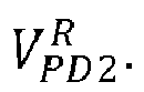
- V PD 1 R and V PD 2 R measures P T R and P LA R , respectively, in the reference measurement without any sample.
- V PD ⁇ 2 S R 2 ⁇ / 100 B ⁇ 1 - H S ⁇ P T S
- K cal R 1 ⁇ ⁇ A R 2 ⁇ ⁇ B
- K cal is a calibration factor depending on the beam splitter and photodiodes, known by a person skilled in the art.
- H s 1 - K cal ⁇ V PD ⁇ 2 S V PD ⁇ 1 S
- H % 100 * 1 - K cal ⁇ V M ⁇ 2 S V PD ⁇ 1 S - 1 - K cal ⁇ V M ⁇ 2 R V PD ⁇ 1 R
- a beamsplitter or mirror for measuring the total k power in which the measurements are done in a reflection mode.
- a collimated beam illuminates perpendicularly a hazy sample and is reflected by a beam splitter BS1.
- the reflected light is deflected by a second beam splitter BS0 in order to measure the low k power and the total k power in a different direction (perpendicular or other) of the illuminating beam in the same way as in the previous embodiment.
- Low k power is measured from the first split beam by means of a spatial filter F and a photodiode PD2 and total k power is measured from the second split beam collecting the whole light power by means of a lens system and another photodiode PD1.
- multiple spatial filters FN for different cut-off angles can be used.
- Low k power referred to different cut-off angles can be measured with different spatial filters placed inside one of the split beam exiting the beamsplitter.
- Spatial filters can be placed preferably uniformly distributed in a plane perpendicular to the light beam direction and close, or touching the beamsplitter, as it is shown in Figure 7c .
- multiple spatial filters for different cut-off angles in a reflection mode can be used.
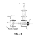
- Low k power referred to different cut-off angles can be measured from one of the beams exiting the second beam splitter, as it is shown in Figure 7d .
- the total power is measured by means of a second spatial filter FT with a high ⁇ c .
- ⁇ c has to be high enough that the spatial filter does not significantly cut any k-vectors.
- Any haze range can be measured accurately choosing adequately the ratio D / L of the spatial filter to measure the total power, as it is shown in table.
- Measurable Haze Range [%] 0-2 0-10 0-25 0-50 0-75 0-99 0-99.99 Minimum D/L of Total K Filter 0,04 0,05 0,06 0,08 0,13 0,84 9,51
- both measurements, low k power and total power can be measured with spatial filters with equal FOVs, i.e low k power is measured with a spatial filter at a distance 1cm whose first aperture is 0.40mm and total k power is measured with a spatial filter at a distance 1cm whose first aperture is 0.40mm too, only differing in the length of the spatial filter. Since FOV is depending on the first aperture and the distance, in this case, both power measurements are related with the same sample's area, and power ratio calculation for haze will be correct. But, both measurements, low k power and total power, can be measured too with spatial filters with different FOVs.
- a beamsplitter or mirror for measuring the total k power in which the measurements are done in a reflection mode.
- a collimated beam illuminates perpendicularly a hazy sample and the reflected light scattering is deflected by a beam splitter in order to measure the low k power and the total power in a different direction (perpendicular or other) of the illuminating beam.
- Scattered light exiting the beam splitter can be measured with the same procedure described in the previous embodiment, that is, using one or two sensors SE and by means of two filters with different D.
- a plurality of spatial filters FN can be used for measure low k power at different cut-off angles, and the total k power.
- Low k power referred to different cut-off angles can be measured with different spatial filters placed inside one of the split beam exiting the beamsplitter. Total power can be measured with one of the spatial filters of the array. Spatial filters can be placed preferably uniformly distributed in a plane perpendicular to the light beam direction and close, or touching the sample, as it is shown in Figure 8c .
- multiple spatial filters for different cut-off angles in a reflection mode can be used.
- Low k power referred to different cut-off angles can be measured from one of the beams exiting a beam splitter used in order to measure the low k power and the total power in a different direction (perpendicular or other) of the illuminating beam as it is shown in Figure 8d .
- the shadow and diffracted image of the sample provided by each group of pixels can be processed by image processing techniques in order to obtain a microscopic resolved image, with a resolution equal to the pixel size and a field of view equal to the image sensor dimensions.
- Image processing techniques to recover amplitude and phase from a diffracted image are well known in holographic reconstruction and lens-free microscopy.
Landscapes
- Physics & Mathematics (AREA)
- Health & Medical Sciences (AREA)
- Life Sciences & Earth Sciences (AREA)
- Chemical & Material Sciences (AREA)
- Analytical Chemistry (AREA)
- Biochemistry (AREA)
- General Health & Medical Sciences (AREA)
- General Physics & Mathematics (AREA)
- Immunology (AREA)
- Pathology (AREA)
- Investigating Or Analysing Materials By Optical Means (AREA)
- Mathematical Physics (AREA)
Abstract
Description
- The present invention relates to an apparatus for measuring light scattering, haze and other related properties produced by non uniform liquid, solid or gas samples, both in their bulk or surface state.
- Light that is scattered upon passing through a film or sheet of a material can produce a hazy or smoky field when objects are viewed through the material. Another effect can be veiling glare, as occurs in an automobile windshield when driving facing the sun. Turbidity is a monitoring parameter used in various fields, such as food industry, water contamination control and water purification plants. Turbidimeters are used, for instance, in wine and beer production, in order to measure the total suspended solids value in a liquid sample. Very often, an inspection image is also needed in order to identify different suspended solids in the sample and their concentrations. Another example could be cheese production in which milk coagulation scattering and clustering effects are off-line monitored.
- Haze, glare and gloss are scattering-related monitoring parameters also used in roll-to-roll plastic sheet, glass or film production. These parameters are usually measured off-line with different devices, of high cost and large dimensions, in order to detect imperfections and inhomogeneities in the samples. After the imperfection is detected, an image usually follows to determine its nature. It is desirable to measure such image using the same apparatus that is used to evaluate the scattering.
Haze in a film results in a cloudy appearance or poorer clarity of objects when viewed through the film. This is why haze is a parameter that characterizes transparent and translucent films, not opaque films
A Hazemeter measures the haze (light forward scattering) and the light transmitting properties of plastic sheets, film, glass, and liquid products. They are used in many industry fields such as adhesives, Automotive, Ceramics, Chemical, Coatings, Cosmetics, Detergents, Dyestuffs, Food, Glazing products, Printing Inks, Packaging materials, Petroleum, Pharmaceuticals, Plastics, Polishes, Resins, Varnish, Waxes, etc... American Society for Testing and Materials (ASTM) standards establish that haze is the ratio of the light scattered at an angle larger than 2.5 degree and the total light exiting the sample at any angle.
Haze measurement is regulated by the standard ASTM D 1003 "Standard Test Methods for Haze and Luminous Transmittance of Transparent Plastics" and ASTM E 167/ASTM E2387 for haze greater than 30%.
The ASTM procedure to measure haze consists on an easy calculation from four measurements:


- A light k vector is defined as a magnitude and direction of a light beam: Its magnitude is either the wavenumber or angular wavenumber of the wave (inversely proportional to the wavelength), and its direction is ordinarily the direction of wave propagation.
- High k vectors are defined as vectors whose direction forms an angle equal or greater than 2.5° with respect to the direction perpendicular to the sample surface under test. Low k vectors are defined as those whose direction forms an angle lower than 2.5°. The standard haze measurement aims to obtain the power ratio between the high k and the total k vectors emerging from the sample. A final correction with the haze reference is mandatory to reduce, if not eliminate, systematic errors.
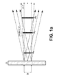
- Every commercial hazemeter that, according to ASTM standards, carries out two separate measurements, of the high k and total k vectors, requires blocking or rejecting the low k vectors. This comes always with an issue: there is a minimum distance between the sample and optical detector element that should exist in order to avoid geometrical errors. This is represented in
Figure 1a . When the distance between the sample and the low k light blocking or rejecting stage is too short (d1), too many high k vectors are blocked (besides the low k vectors). At increasing distances this effect is reduced, e.g. d2 is lower than for d1. In order that this effect is negligible, one has to reach a minimum distance (d3), which depends on the beam size (D). Note that also the blocking stage has to be increased in diameter with the distance because of intrinsic diffraction effects. Note that d3 also sets the resolution of this scheme. The smaller the distance the larger the contribution from k vectors further from 2.5 degree angle. In other words, the larger d3 is, the clearer the separation between k vectors. This is a important drawback because, correspondingly, the device requires a minimum size, sometimes this becoming an unpractical feature, especially for in-line measurements. Commercial hazemeters usually use an integration sphere (seeFig. 1 b) , which is an optical device that concentrates all the k vectors to one point inside it, with an on/off window. The collimated light source and an integrating sphere must be placed on opposite sides of the sample and must be structurally interconnected in order to preserve the alignment between source and integrating sphere. When the window is open, low k vectors escape from the integration sphere and an optical sensor inside the integration sphere measures only the high k vectors. When the window is closed, the optical sensor measures the total k vectors. InFig. 1b , distance d3 has been defined as the minimum distance between the sample and the blocking stage in order to separate high from low k vectors. For a hazemeter according to the state of the art, with a beam diameter of 2.5 cm, the minimum d needed applying ASTM D1003 (that is, the needed Integration Sphere diameter) is 28.63 cm. This distance limits the size and configuration of the device. - An alternative way of calculating the haze of a sample is described in
WO2010/104699 . The method comprises measuring the power of high k vectors and adding it to that of low k-vectors. This method however has the drawback that rays with a k-vector greater than the radius of the sensor will not be detected. The detector must be thus adapted to the dimensions of the sample. A sensor is expensive and thus, having a set of them for different samples results costly. - There is thus a need for a method and device for measuring light scattering with smaller size, lower cost components, making it also possible to be used for in-line measurements.
- The invention, in its simplest form, includes a light source, a sample holder, at least one light sensor and at least one spatial filter, each filter having two apertures of equal or different diameters for removing the scattered light beams above a predefined angle, that we name cut-off angle. In other embodiments, an array of spatial filters having different cut-off angles can be used. In this case, multiple photodetectors or an array of photodetectors, such as complementary metal-oxide-semiconductor (CMOS) or charge-coupled device (CCD) light sensor, are preferred. In other cases, one or two photo diodes might be sufficient. In some cases the sample holder may not be needed, as it is for example for in-line measurements of thin film sheets. The filter can be continuous, with two apertures, or be constituted by two separate apertures, which must meet the following relation:

wherein αc is the scattering angle, D1 an D2 the diameters of the apertures and L the total length of the filter in the direction of the beam. The combination of at least one spatial filter with an light sensor offers the possibility to obtain at the same time a microscopic image of the illuminated area (within the sensor area) as well as values of the light scattering, i.e. a haze value at predefined cut-off angles if the measurement is in transmission from a gel or solid sample, a gloss value if the measurement is in reflection from a gel or solid sample, or a turbidity value if the measurement is in transmission from a liquid sample. The device can also be used as a turbidimeter if the sample is a liquid one. Other advantageous embodiments are defined in the dependent claims. - To complete the description and in order to provide for a better understanding of the invention, a set of drawings is provided. Said drawings illustrate a preferred embodiment of the invention, which should not be interpreted as restricting the scope of the invention, but just as an example of how the invention can be embodied.
-
Figures 1 a and 1 b show the technical problem related with the prior art. -
Figure 2 shows a spatial filter, in the form of a cylinder or two apertures -
Figure 3 is similar toFigure 2 , the filters having apertures of different diameters. -
Figure 4 shows the relationship between the diameter of the beam, the field of view and the diameter(s) and length of the filter. -
Figure 5 is a graph of the low k power versus scattering for various apertures. -
Figure 6 is a graph of the low k power versus different apertures for three samples with different haze. -
Figures 7a -7d show embodiments of the invention using a beamsplitter to measure total k power and low k power. -
Figures 8a-8d show embodiments of the invention using at least two filters, one for measuring the low k power and another one for measuring the total k power. - The invention filters and measures the optical power of a representative part of low k vectors (defined as low k power) and a representative part of the total k vectors (defined as a total k power) power by means of at least one filter with two apertures. The light source can be of any predetermined wavelength or white, tunable or it can be a light emitting diode. In this way a simplified, portable and compact device for measuring different parameters like haze, turbidity, etc. can be built, for any sample and without the need of changing detectors.
- Indicating with PLA the light power corresponding to beams (k vectors) with angles lower than 2.5°, PHA the light power corresponding to beams (k vectors) with angles equal or greater than 2.5°, and PT the total light power emerging from sample::

- And consequently:

- The haze expression (1) as a function of low and total k vectors powers:


- In
Figure 2 (left) the cut-off αc angle of the k vectors passing through a cylinder tube is defined by the diameter D and length L of the tube.
- The same αc cut-off angle can be achieved with two aligned circular apertures with equal diameters and external surfaces separated at a distance L, as it is shown in
Figure 2 (right). -
Figure 3 (left) shows a filter consisting in a conical tube defined by its length and two different apertures in its edges and a filter consisting in two apertures separated a distance L (right). The cut-off αc angle of the k vectors passing through the apertures is defined by the diameters D1 , D2 and length L.
- The filters could be advantageously made of a material (at least the inner walls) with high absorption over the spectrum of the light of the source. Examples of suitable materials are plastic (preferentially of black color), slate and teflon®. When the filter presents a residual reflection, it may be preferable to use the apertures design in order to avoid possible internal reflection from the inner walls of the cylindrical tube.
- The circular surface area of the spot illuminating the sample with diameter Dc is the field of view (FOV) of the spatial filter at a distance d. Only beamlets (k vectors) coming from points inside the FOV will reach the photodetector. Dc is defined as:

- As shown in
Figure 4 , the circular surface area of the spot exiting the spatial filter and arriving to the sensor with diameter Dr is the back field of view of the spatial filter at a distance dr. The sensor surface must be equal or larger than the spot surface Dr in order to contain all the light power exiting the spatial filter. In case dr=0, sensor surface must be equal or larger than the second aperture. Dr is defined as:
- The embodiment of
Figure 4 shows a collimated beam, with diameter Ds, , illuminating a sample and two separate apertures. A diverging beam, i.e coming from a hazy sample placed before the filter, passes through the spatial filter. The spatial filter has a particular FOV equal to Dc. That means the optical sensor after the spatial filter only "see" Dc surface of the sample. Taking this into account, it is necessary that the input collimated beam has a spot diameter Ds equal or larger than Dc. If Ds were smaller than Dc the sensor would see a non-illuminated part of the sample. The spatial filter blocks any k vector with angle higher than ac . - The light sensor can be placed touching the D2 aperture or at a distance. Its active area, with diameter Dr, has to be equal or larger than the area of the beam spot exiting the spatial filter in order to avoid errors in power light measurement.
-
Figure 5 shows the calculated low k power as a function of scattering for various spatial filter apertures. Scattering here is represented as scattering percentage (the percentage of scattered light power related to total light power). The slope of the curves and the nominal value for a particular scattering, increases with D. That means the invention has better accuracy measuring low k vectors using spatial filters with higher apertures. This design condition defines the effective area of the photodiode or of the image sensor, because a sensor area equal or larger than the spatial filter area is needed in order to measure the low k power without errors. -
Figure 6 shows the calculated low k power as a function of the spatial filter aperture for various samples with different scattering percentage. Low k power increases with filter diameter but the slope of the curves, and the nominal value for a particular diameter, decrease with scattering. That means for a particular D, the invention has better accuracy measuring low k vectors in samples with lower scattering. - The preferred conditions to enhance the accuracy of the invention are: a short distance between sample and spatial filter, large diameters of apertures and large area of the photodetector or light sensor.
- In a first embodiment, total power is measured by means of a beam splitter or mirror (
Figure 7a ). The scattered light is split into two beams; the low k vectors' power is measured from the first beam by means of a spatial filter F as shown inFigure 7a , with αc =2.5° (that is, in this particular example, we measure haze as in the definition given above). The total power is measured collecting the whole power of the second beam. As one possible implementation of this embodiment,Figure 7a shows a light source SO, preferably a white light source, such as a light emitting diode LED, with a collimation system for the light source, preferably a Köhler system, illuminating a hazy sample, a beam splitter BS0, preferably with 50/50 split percentages, a lens or lenses to collect the total forward scattered power and a first photodiode to measure it, a spatial filter and a second photodiode to measure the low k power. - To achieve a collimated and homogeneous input beam a Köhler illumination followed by a collimation lens setup is used. A white light source LED illuminates the collimation system and after a 1mm diameter aperture, the homogeneous and collimated beam impinges on the hazy sample. A 50/50 beam splitter splits it into two beams. One beam is collected by the photodiode PD1 which measures a signal proportional to the total power transmitted. The second beam goes through two aligned 1 mm apertures filters and is then measured by the photodiode PD2. This measurement is proportional to the low k vectors power. The diameters and the separation sets the filter cut-off angle at 2.5°, angle established by the haze standards EPA 180.1 and ISO 7027.
- The haze value in the first preferred embodiment can be calculated:

- V PD1 S is the voltage in the PD1 photodiode output, R1 is its responsivity in [V/W], and A is the percentage of the light split to into the first beam.

- V PD2 S is the voltage in the PD2 photodiode output, R2 is its responsivity in [V/W], and B is the percentage of the light split into the second beam.
- A and B are factors which are known to the skilled person and depend on the beam splitter. If a 50/50 beam splitter is used, A=B.
- V PD1 R and V PD2 R measures PT R and PLA R, respectively, in the reference measurement without any sample.
- According to the previous definitions of


- Substituting in equation (8):

- Dividing equation (10) by (7):


- Kcal is a calibration factor depending on the beam splitter and photodiodes, known by a person skilled in the art.
- Therefore the haze sample Hs can be calculated as

- Similarly for the measured reference voltages:

- And the haze value becomes:

- The procedure is as follows:
- 1. Calculate Kcal , depending on the beam splitter and photodiodes.
- 2. Measure without any sample the voltage values of

- 3. Measure without a hazy sample the voltage values of


- 4. Apply to the low k measurement the error correction of the equation (11) obtaining


- 5. Calculate Equation (13) with the previous calculated and measured values.
- There are other possible embodiments involving the use of a beamsplitter or mirror for measuring the total k power in which the measurements are done in a reflection mode. As it can be seen in
Figure 7b ... in a reflection mode, a collimated beam illuminates perpendicularly a hazy sample and is reflected by a beam splitter BS1. The reflected light is deflected by a second beam splitter BS0 in order to measure the low k power and the total k power in a different direction (perpendicular or other) of the illuminating beam in the same way as in the previous embodiment. Low k power is measured from the first split beam by means of a spatial filter F and a photodiode PD2 and total k power is measured from the second split beam collecting the whole light power by means of a lens system and another photodiode PD1. - In another implementation, multiple spatial filters FN for different cut-off angles can be used.
Low k power referred to different cut-off angles can be measured with different spatial filters placed inside one of the split beam exiting the beamsplitter. Spatial filters can be placed preferably uniformly distributed in a plane perpendicular to the light beam direction and close, or touching the beamsplitter, as it is shown inFigure 7c . - In another implementation, multiple spatial filters, for different cut-off angles in a reflection mode can be used. Low k power referred to different cut-off angles can be measured from one of the beams exiting the second beam splitter, as it is shown in
Figure 7d . - In another embodiment, shown in
Figure 8a , the low k vector's power is measured by means of a spatial filter FL, with αc =2.5 degree. The total power is measured by means of a second spatial filter FT with a high αc. To avoid errors in the total power measurement αc has to be high enough that the spatial filter does not significantly cut any k-vectors. Any haze range can be measured accurately choosing adequately the ratio D/L of the spatial filter to measure the total power, as it is shown in table.Measurable Haze Range [%] 0-2 0-10 0-25 0-50 0-75 0-99 0-99.99 Minimum D/L of Total K Filter 0,04 0,05 0,06 0,08 0,13 0,84 9,51 - In this geometry both measurements, low k power and total power, can be measured with spatial filters with equal FOVs, i.e low k power is measured with a spatial filter at a distance 1cm whose first aperture is 0.40mm and total k power is measured with a spatial filter at a distance 1cm whose first aperture is 0.40mm too, only differing in the length of the spatial filter. Since FOV is depending on the first aperture and the distance, in this case, both power measurements are related with the same sample's area, and power ratio calculation for haze will be correct. But, both measurements, low k power and total power, can be measured too with spatial filters with different FOVs. That is different first apertures diameters at the same distance d, or equal first apertures diameters at different distances d, or combining different first apertures with different distances d. i.e low k power is measured with a spatial filter at a
distance 1 cm whose first aperture is 0.40mm and total k power is measured with a spatial filter at a distance 1cm whose first aperture is 1.50mm, The consequence is that both power measurements are referred to different size areas of the sample and for this reason the power ratio calculation for haze will be incorrect unless both measurements were adequately weighted with a rescaling factor according to:
- To avoid weighting errors short distance between sample and spatial filter is preferred. There are other possible embodiments involving the use of a beamsplitter or mirror for measuring the total k power in which the measurements are done in a reflection mode. As it can be seen in
figure 8b , in a reflection mode, a collimated beam illuminates perpendicularly a hazy sample and the reflected light scattering is deflected by a beam splitter in order to measure the low k power and the total power in a different direction (perpendicular or other) of the illuminating beam. Scattered light exiting the beam splitter can be measured with the same procedure described in the previous embodiment, that is, using one or two sensors SE and by means of two filters with different D. - In another implementation, a plurality of spatial filters FN can be used for measure low k power at different cut-off angles, and the total k power.
- Low k power referred to different cut-off angles can be measured with different spatial filters placed inside one of the split beam exiting the beamsplitter. Total power can be measured with one of the spatial filters of the array. Spatial filters can be placed preferably uniformly distributed in a plane perpendicular to the light beam direction and close, or touching the sample, as it is shown in
Figure 8c . - In another implementation, multiple spatial filters, for different cut-off angles in a reflection mode can be used. Low k power referred to different cut-off angles can be measured from one of the beams exiting a beam splitter used in order to measure the low k power and the total power in a different direction (perpendicular or other) of the illuminating beam as it is shown in
Figure 8d . - Since a plurality of spatial filters is used to measure low k power at different cut-off angles, these scattering power values can be represented in a scattering radiation diagram. An example of a plurality of spatial filters for measuring a scattering radiation diagram for angles between 1.25 and 9.31 degree is shown in the following table:

- Since an image sensor is used to measure the light power of a plurality of spatial filters, and each group of pixels is in charge of measure the light power of each spatial filter, the shadow and diffracted image of the sample provided by each group of pixels can be processed by image processing techniques in order to obtain a microscopic resolved image, with a resolution equal to the pixel size and a field of view equal to the image sensor dimensions. Image processing techniques to recover amplitude and phase from a diffracted image are well known in holographic reconstruction and lens-free microscopy.
- In this text, the term "comprises" and its derivations (such as "comprising", etc.) should not be understood in an excluding sense, that is, these terms should not be interpreted as excluding the possibility that what is described and defined may include further elements, steps, etc.
- On the other hand, the invention is obviously not limited to the specific embodiment(s) described herein, but also encompasses any variations that may be considered by any person skilled in the art (for example, as regards the choice of materials, dimensions, components, configuration, etc.), within the general scope of the invention as defined in the claims.
Claims (11)
- Apparatus for measuring light scattering of a sample S comprising:- a light beam source SO;- means for collimating the beam and making it impinge on the sample S in a perpendicular direction;- at least one light sensor (PD1, SE)- at least one spatial filter F between the sample and the image sensor, provided with two apertures related by the following equation:

wherein αc is the scattering angle, D1 an D2 the diameters of the apertures and L the total length of the filter in the direction of the beam- means for measuring the total power reaching the sensor- and means for measuring the power of beams with a k vector lower than αc.
after the beam traverses the filter. - Apparatus according to claim 1 wherein the means for measuring the total power are a second sensor PD1 and a beam splitter or dielectric mirror BS0 for splitting the beam in two directions, one towards the filter F and the first sensor PD1 and the second direction towards a second sensor PD2.
- Apparatus according to claim 2 further comprising a second beam splitter or dielectric mirror between the sample S and the source SO for allowing the apparatus to work in reflection mode.
- Apparatus according to claims 2 or 3 comprising a plurality of N filters FN, N being greater or equal than 2, with different apertures D.
- Apparatus according to any of the previous claims wherein the sensor or sensors are photodiodes.
- Apparatus according to claim 1 wherein the means for measuring the total power are a second filter FT in parallel with the first filter FL between the sample S and the sensor SE, the second filter FT having greater apertures than the first filter.
- Apparatus according to claim 6 comprising a plurality N of filters FN, N being equal or greater than 3, with different apertures D.
- Apparatus according to claims 6 or 7 further comprising a beam splitter or mirror BS1 for allowing the apparatus to work in reflection mode.
- Apparatus according to any of the previous claims wherein the sensor or sensors SE are a CMOS or CCD camera.
- Apparatus according to any of the previous claims where the source SO is of any predetermined wavelength or white, tunable, or a light emitting diode.
- Use of the apparatus of any of the previous claims as a turbidimeter, hazemeter or glossmeter.
Priority Applications (3)
| Application Number | Priority Date | Filing Date | Title |
|---|---|---|---|
| EP14382043.9A EP2905605B1 (en) | 2014-02-06 | 2014-02-06 | Apparatus for measuring light scattering |
| US14/616,062 US9857300B2 (en) | 2014-02-06 | 2015-02-06 | Apparatus for measuring light scattering |
| US15/844,803 US10302560B2 (en) | 2014-02-06 | 2017-12-18 | Apparatus for measuring light scattering |
Applications Claiming Priority (1)
| Application Number | Priority Date | Filing Date | Title |
|---|---|---|---|
| EP14382043.9A EP2905605B1 (en) | 2014-02-06 | 2014-02-06 | Apparatus for measuring light scattering |
Publications (2)
| Publication Number | Publication Date |
|---|---|
| EP2905605A1 true EP2905605A1 (en) | 2015-08-12 |
| EP2905605B1 EP2905605B1 (en) | 2023-05-10 |
Family
ID=50073130
Family Applications (1)
| Application Number | Title | Priority Date | Filing Date |
|---|---|---|---|
| EP14382043.9A Active EP2905605B1 (en) | 2014-02-06 | 2014-02-06 | Apparatus for measuring light scattering |
Country Status (2)
| Country | Link |
|---|---|
| US (2) | US9857300B2 (en) |
| EP (1) | EP2905605B1 (en) |
Cited By (2)
| Publication number | Priority date | Publication date | Assignee | Title |
|---|---|---|---|---|
| CN106471355A (en) * | 2014-06-18 | 2017-03-01 | 栗田工业株式会社 | Coagulation monitoring arrangement, coagulation monitor method and coagulation system |
| WO2017180919A1 (en) * | 2016-04-15 | 2017-10-19 | Phoseon Technology, Inc. | Method and system for emission of and curing via narrow width radiation |
Families Citing this family (9)
| Publication number | Priority date | Publication date | Assignee | Title |
|---|---|---|---|---|
| EP2905605B1 (en) * | 2014-02-06 | 2023-05-10 | Fundació Institut de Ciències Fotòniques | Apparatus for measuring light scattering |
| JP6657794B2 (en) * | 2015-10-30 | 2020-03-04 | 大日本印刷株式会社 | Light diffusivity measuring apparatus and light diffusivity measuring method |
| CN106198399B (en) * | 2016-08-17 | 2023-10-27 | 远方谱色科技有限公司 | Definition measuring device |
| CN106501184B (en) * | 2016-10-25 | 2020-07-28 | 成都光明光电股份有限公司 | Optical glass measuring device and measuring method thereof |
| US11327012B2 (en) * | 2018-05-07 | 2022-05-10 | Unm Rainforest Innovations | Method and system for in-line optical scatterometry |
| US12416580B2 (en) | 2018-05-07 | 2025-09-16 | Unm Rainforest Innovations | Method and system for in-line optical scatterometry |
| DE102019116067A1 (en) * | 2019-06-13 | 2020-12-17 | Sick Ag | OPTOELECTRONIC SENSOR SYSTEM FOR DETECTING OBJECTS IN A MONITORING AREA |
| US12399120B2 (en) | 2019-11-01 | 2025-08-26 | Unm Rainforest Innovations | In-line angular optical multi-point scatterometry for nanomanufacturing systems |
| KR20260061583A (en) * | 2024-10-28 | 2026-05-06 | 한양대학교 산학협력단 | EUV flare measurement device, measurement method, and measurement system, and filter structure used therein |
Citations (2)
| Publication number | Priority date | Publication date | Assignee | Title |
|---|---|---|---|---|
| DE4137141A1 (en) * | 1990-11-29 | 1992-06-04 | Bando Chemical Ind | Automated visual testing of objects - measuring diffuse and uniform light transmitted or reflected by object |
| US20100226524A1 (en) * | 2009-03-09 | 2010-09-09 | Honeywell International Inc. | Apparatus and method for measuring haze of sheet materials or other materials |
Family Cites Families (6)
| Publication number | Priority date | Publication date | Assignee | Title |
|---|---|---|---|---|
| US4160914A (en) * | 1977-12-16 | 1979-07-10 | Monitek, Inc. | Apparatus for measuring of particulate scattering in fluids |
| US5093837A (en) * | 1991-03-08 | 1992-03-03 | S-Tron | Baffle for attenuating off-axis light emissions |
| US6741730B2 (en) * | 2001-08-10 | 2004-05-25 | Visiongate, Inc. | Method and apparatus for three-dimensional imaging in the fourier domain |
| CA2577260A1 (en) * | 2004-08-16 | 2006-02-23 | Bacterioscan | Detection of bacteria in fluids |
| US20080106737A1 (en) * | 2005-08-16 | 2008-05-08 | Amnon Weichselbaum | Detecting and counting bacteria suspended in biological fluids |
| EP2905605B1 (en) * | 2014-02-06 | 2023-05-10 | Fundació Institut de Ciències Fotòniques | Apparatus for measuring light scattering |
-
2014
- 2014-02-06 EP EP14382043.9A patent/EP2905605B1/en active Active
-
2015
- 2015-02-06 US US14/616,062 patent/US9857300B2/en not_active Expired - Fee Related
-
2017
- 2017-12-18 US US15/844,803 patent/US10302560B2/en active Active
Patent Citations (3)
| Publication number | Priority date | Publication date | Assignee | Title |
|---|---|---|---|---|
| DE4137141A1 (en) * | 1990-11-29 | 1992-06-04 | Bando Chemical Ind | Automated visual testing of objects - measuring diffuse and uniform light transmitted or reflected by object |
| US20100226524A1 (en) * | 2009-03-09 | 2010-09-09 | Honeywell International Inc. | Apparatus and method for measuring haze of sheet materials or other materials |
| WO2010104699A2 (en) | 2009-03-09 | 2010-09-16 | Honeywell International Inc. | Apparatus and method for measuring haze of sheet materials or other materials |
Cited By (3)
| Publication number | Priority date | Publication date | Assignee | Title |
|---|---|---|---|---|
| CN106471355A (en) * | 2014-06-18 | 2017-03-01 | 栗田工业株式会社 | Coagulation monitoring arrangement, coagulation monitor method and coagulation system |
| WO2017180919A1 (en) * | 2016-04-15 | 2017-10-19 | Phoseon Technology, Inc. | Method and system for emission of and curing via narrow width radiation |
| US10025078B2 (en) | 2016-04-15 | 2018-07-17 | Phoseon Technology, Inc. | Method and system for emission of and curing via narrow width radiation |
Also Published As
| Publication number | Publication date |
|---|---|
| EP2905605B1 (en) | 2023-05-10 |
| US20180149589A1 (en) | 2018-05-31 |
| US20150219555A1 (en) | 2015-08-06 |
| US9857300B2 (en) | 2018-01-02 |
| US10302560B2 (en) | 2019-05-28 |
Similar Documents
| Publication | Publication Date | Title |
|---|---|---|
| US10302560B2 (en) | Apparatus for measuring light scattering | |
| CN102575985B (en) | For determining surveying instrument and the method for the characteristic of article and surface thereof | |
| KR102444477B1 (en) | water quality analyzer | |
| US11747257B2 (en) | Particle characterization | |
| EP0899548B1 (en) | Cross-correlation method and apparatus for suppressing the effects of multiple scattering | |
| EP2081015A2 (en) | Apparatus for inspecting food | |
| KR20140011258A (en) | Method of detection of defects and defects detection device | |
| US20160252453A1 (en) | Array based sample characterization | |
| JP2013044729A (en) | Coating state measuring method | |
| CN109115682B (en) | Spectrometer for detecting liquid and solid components and detection method thereof | |
| KR930703594A (en) | Simultaneous Multi-Angle / Multi-wavelength Elliptical Polarimeter and Measurement Method | |
| EP3077796A1 (en) | Optical measurements of liquids having free surface | |
| US20150276594A1 (en) | Method and apparatus for measuring turbidity | |
| CN101498665A (en) | Sulphur dioxide gas concentration detection apparatus based on associated spectrum technology | |
| CN101858856A (en) | Method and apparatus for characterizing thin silicon layers on optically transparent substrates | |
| US9632025B2 (en) | Method and measuring device for continuously measuring the abbe number | |
| TW201447266A (en) | Method and device for detecting fibrous materials such as hair | |
| CN103884684B (en) | A kind of optical system of high accuracy number V-prism refractometer | |
| CN106198399B (en) | Definition measuring device | |
| JP2012037507A (en) | Foreign matter inspection method and device for fluid article | |
| CN204649607U (en) | A kind of Rapid food detection instrument | |
| Oliveira et al. | Development and characterization of a low cost sediment concentration optical sensor | |
| CN111693460A (en) | Detection apparatus based on polarized light beam saturated absorption spectrum | |
| JP2019211456A (en) | Quality inspection device for fruits, vegetables, and fruit juice | |
| Barre et al. | Moisture measurement for quality and control applications |
Legal Events
| Date | Code | Title | Description |
|---|---|---|---|
| PUAI | Public reference made under article 153(3) epc to a published international application that has entered the european phase |
Free format text: ORIGINAL CODE: 0009012 |
|
| AK | Designated contracting states |
Kind code of ref document: A1 Designated state(s): AL AT BE BG CH CY CZ DE DK EE ES FI FR GB GR HR HU IE IS IT LI LT LU LV MC MK MT NL NO PL PT RO RS SE SI SK SM TR |
|
| AX | Request for extension of the european patent |
Extension state: BA ME |
|
| 17P | Request for examination filed |
Effective date: 20160212 |
|
| RBV | Designated contracting states (corrected) |
Designated state(s): AL AT BE BG CH CY CZ DE DK EE ES FI FR GB GR HR HU IE IS IT LI LT LU LV MC MK MT NL NO PL PT RO RS SE SI SK SM TR |
|
| 17Q | First examination report despatched |
Effective date: 20160624 |
|
| STAA | Information on the status of an ep patent application or granted ep patent |
Free format text: STATUS: EXAMINATION IS IN PROGRESS |
|
| GRAP | Despatch of communication of intention to grant a patent |
Free format text: ORIGINAL CODE: EPIDOSNIGR1 |
|
| STAA | Information on the status of an ep patent application or granted ep patent |
Free format text: STATUS: GRANT OF PATENT IS INTENDED |
|
| INTG | Intention to grant announced |
Effective date: 20221123 |
|
| GRAS | Grant fee paid |
Free format text: ORIGINAL CODE: EPIDOSNIGR3 |
|
| GRAA | (expected) grant |
Free format text: ORIGINAL CODE: 0009210 |
|
| STAA | Information on the status of an ep patent application or granted ep patent |
Free format text: STATUS: THE PATENT HAS BEEN GRANTED |
|
| AK | Designated contracting states |
Kind code of ref document: B1 Designated state(s): AL AT BE BG CH CY CZ DE DK EE ES FI FR GB GR HR HU IE IS IT LI LT LU LV MC MK MT NL NO PL PT RO RS SE SI SK SM TR |
|
| REG | Reference to a national code |
Ref country code: GB Ref legal event code: FG4D |
|
| REG | Reference to a national code |
Ref country code: AT Ref legal event code: REF Ref document number: 1567149 Country of ref document: AT Kind code of ref document: T Effective date: 20230515 Ref country code: CH Ref legal event code: EP |
|
| REG | Reference to a national code |
Ref country code: DE Ref legal event code: R096 Ref document number: 602014086885 Country of ref document: DE |
|
| REG | Reference to a national code |
Ref country code: IE Ref legal event code: FG4D |
|
| P01 | Opt-out of the competence of the unified patent court (upc) registered |
Effective date: 20230504 |
|
| REG | Reference to a national code |
Ref country code: LT Ref legal event code: MG9D |
|
| REG | Reference to a national code |
Ref country code: NL Ref legal event code: MP Effective date: 20230510 |
|
| REG | Reference to a national code |
Ref country code: AT Ref legal event code: MK05 Ref document number: 1567149 Country of ref document: AT Kind code of ref document: T Effective date: 20230510 |
|
| PG25 | Lapsed in a contracting state [announced via postgrant information from national office to epo] |
Ref country code: SE Free format text: LAPSE BECAUSE OF FAILURE TO SUBMIT A TRANSLATION OF THE DESCRIPTION OR TO PAY THE FEE WITHIN THE PRESCRIBED TIME-LIMIT Effective date: 20230510 Ref country code: PT Free format text: LAPSE BECAUSE OF FAILURE TO SUBMIT A TRANSLATION OF THE DESCRIPTION OR TO PAY THE FEE WITHIN THE PRESCRIBED TIME-LIMIT Effective date: 20230911 Ref country code: NO Free format text: LAPSE BECAUSE OF FAILURE TO SUBMIT A TRANSLATION OF THE DESCRIPTION OR TO PAY THE FEE WITHIN THE PRESCRIBED TIME-LIMIT Effective date: 20230810 Ref country code: NL Free format text: LAPSE BECAUSE OF FAILURE TO SUBMIT A TRANSLATION OF THE DESCRIPTION OR TO PAY THE FEE WITHIN THE PRESCRIBED TIME-LIMIT Effective date: 20230510 Ref country code: ES Free format text: LAPSE BECAUSE OF FAILURE TO SUBMIT A TRANSLATION OF THE DESCRIPTION OR TO PAY THE FEE WITHIN THE PRESCRIBED TIME-LIMIT Effective date: 20230510 Ref country code: AT Free format text: LAPSE BECAUSE OF FAILURE TO SUBMIT A TRANSLATION OF THE DESCRIPTION OR TO PAY THE FEE WITHIN THE PRESCRIBED TIME-LIMIT Effective date: 20230510 |
|
| PG25 | Lapsed in a contracting state [announced via postgrant information from national office to epo] |
Ref country code: RS Free format text: LAPSE BECAUSE OF FAILURE TO SUBMIT A TRANSLATION OF THE DESCRIPTION OR TO PAY THE FEE WITHIN THE PRESCRIBED TIME-LIMIT Effective date: 20230510 Ref country code: PL Free format text: LAPSE BECAUSE OF FAILURE TO SUBMIT A TRANSLATION OF THE DESCRIPTION OR TO PAY THE FEE WITHIN THE PRESCRIBED TIME-LIMIT Effective date: 20230510 Ref country code: LV Free format text: LAPSE BECAUSE OF FAILURE TO SUBMIT A TRANSLATION OF THE DESCRIPTION OR TO PAY THE FEE WITHIN THE PRESCRIBED TIME-LIMIT Effective date: 20230510 Ref country code: LT Free format text: LAPSE BECAUSE OF FAILURE TO SUBMIT A TRANSLATION OF THE DESCRIPTION OR TO PAY THE FEE WITHIN THE PRESCRIBED TIME-LIMIT Effective date: 20230510 Ref country code: IS Free format text: LAPSE BECAUSE OF FAILURE TO SUBMIT A TRANSLATION OF THE DESCRIPTION OR TO PAY THE FEE WITHIN THE PRESCRIBED TIME-LIMIT Effective date: 20230910 Ref country code: HR Free format text: LAPSE BECAUSE OF FAILURE TO SUBMIT A TRANSLATION OF THE DESCRIPTION OR TO PAY THE FEE WITHIN THE PRESCRIBED TIME-LIMIT Effective date: 20230510 Ref country code: GR Free format text: LAPSE BECAUSE OF FAILURE TO SUBMIT A TRANSLATION OF THE DESCRIPTION OR TO PAY THE FEE WITHIN THE PRESCRIBED TIME-LIMIT Effective date: 20230811 |
|
| PG25 | Lapsed in a contracting state [announced via postgrant information from national office to epo] |
Ref country code: FI Free format text: LAPSE BECAUSE OF FAILURE TO SUBMIT A TRANSLATION OF THE DESCRIPTION OR TO PAY THE FEE WITHIN THE PRESCRIBED TIME-LIMIT Effective date: 20230510 |
|
| PG25 | Lapsed in a contracting state [announced via postgrant information from national office to epo] |
Ref country code: SK Free format text: LAPSE BECAUSE OF FAILURE TO SUBMIT A TRANSLATION OF THE DESCRIPTION OR TO PAY THE FEE WITHIN THE PRESCRIBED TIME-LIMIT Effective date: 20230510 |
|
| PG25 | Lapsed in a contracting state [announced via postgrant information from national office to epo] |
Ref country code: SM Free format text: LAPSE BECAUSE OF FAILURE TO SUBMIT A TRANSLATION OF THE DESCRIPTION OR TO PAY THE FEE WITHIN THE PRESCRIBED TIME-LIMIT Effective date: 20230510 Ref country code: SK Free format text: LAPSE BECAUSE OF FAILURE TO SUBMIT A TRANSLATION OF THE DESCRIPTION OR TO PAY THE FEE WITHIN THE PRESCRIBED TIME-LIMIT Effective date: 20230510 Ref country code: RO Free format text: LAPSE BECAUSE OF FAILURE TO SUBMIT A TRANSLATION OF THE DESCRIPTION OR TO PAY THE FEE WITHIN THE PRESCRIBED TIME-LIMIT Effective date: 20230510 Ref country code: EE Free format text: LAPSE BECAUSE OF FAILURE TO SUBMIT A TRANSLATION OF THE DESCRIPTION OR TO PAY THE FEE WITHIN THE PRESCRIBED TIME-LIMIT Effective date: 20230510 Ref country code: DK Free format text: LAPSE BECAUSE OF FAILURE TO SUBMIT A TRANSLATION OF THE DESCRIPTION OR TO PAY THE FEE WITHIN THE PRESCRIBED TIME-LIMIT Effective date: 20230510 Ref country code: CZ Free format text: LAPSE BECAUSE OF FAILURE TO SUBMIT A TRANSLATION OF THE DESCRIPTION OR TO PAY THE FEE WITHIN THE PRESCRIBED TIME-LIMIT Effective date: 20230510 |
|
| REG | Reference to a national code |
Ref country code: DE Ref legal event code: R097 Ref document number: 602014086885 Country of ref document: DE |
|
| PLBE | No opposition filed within time limit |
Free format text: ORIGINAL CODE: 0009261 |
|
| STAA | Information on the status of an ep patent application or granted ep patent |
Free format text: STATUS: NO OPPOSITION FILED WITHIN TIME LIMIT |
|
| 26N | No opposition filed |
Effective date: 20240213 |
|
| PG25 | Lapsed in a contracting state [announced via postgrant information from national office to epo] |
Ref country code: SI Free format text: LAPSE BECAUSE OF FAILURE TO SUBMIT A TRANSLATION OF THE DESCRIPTION OR TO PAY THE FEE WITHIN THE PRESCRIBED TIME-LIMIT Effective date: 20230510 |
|
| PG25 | Lapsed in a contracting state [announced via postgrant information from national office to epo] |
Ref country code: SI Free format text: LAPSE BECAUSE OF FAILURE TO SUBMIT A TRANSLATION OF THE DESCRIPTION OR TO PAY THE FEE WITHIN THE PRESCRIBED TIME-LIMIT Effective date: 20230510 Ref country code: IT Free format text: LAPSE BECAUSE OF FAILURE TO SUBMIT A TRANSLATION OF THE DESCRIPTION OR TO PAY THE FEE WITHIN THE PRESCRIBED TIME-LIMIT Effective date: 20230510 |
|
| REG | Reference to a national code |
Ref country code: DE Ref legal event code: R119 Ref document number: 602014086885 Country of ref document: DE |
|
| PG25 | Lapsed in a contracting state [announced via postgrant information from national office to epo] |
Ref country code: MC Free format text: LAPSE BECAUSE OF FAILURE TO SUBMIT A TRANSLATION OF THE DESCRIPTION OR TO PAY THE FEE WITHIN THE PRESCRIBED TIME-LIMIT Effective date: 20230510 |
|
| REG | Reference to a national code |
Ref country code: CH Ref legal event code: PL |
|
| PG25 | Lapsed in a contracting state [announced via postgrant information from national office to epo] |
Ref country code: LU Free format text: LAPSE BECAUSE OF NON-PAYMENT OF DUE FEES Effective date: 20240206 |
|
| PG25 | Lapsed in a contracting state [announced via postgrant information from national office to epo] |
Ref country code: CH Free format text: LAPSE BECAUSE OF NON-PAYMENT OF DUE FEES Effective date: 20240229 |
|
| GBPC | Gb: european patent ceased through non-payment of renewal fee |
Effective date: 20240206 |
|
| PG25 | Lapsed in a contracting state [announced via postgrant information from national office to epo] |
Ref country code: LU Free format text: LAPSE BECAUSE OF NON-PAYMENT OF DUE FEES Effective date: 20240206 Ref country code: CH Free format text: LAPSE BECAUSE OF NON-PAYMENT OF DUE FEES Effective date: 20240229 |
|
| PG25 | Lapsed in a contracting state [announced via postgrant information from national office to epo] |
Ref country code: BG Free format text: LAPSE BECAUSE OF FAILURE TO SUBMIT A TRANSLATION OF THE DESCRIPTION OR TO PAY THE FEE WITHIN THE PRESCRIBED TIME-LIMIT Effective date: 20230510 |
|
| PG25 | Lapsed in a contracting state [announced via postgrant information from national office to epo] |
Ref country code: BG Free format text: LAPSE BECAUSE OF FAILURE TO SUBMIT A TRANSLATION OF THE DESCRIPTION OR TO PAY THE FEE WITHIN THE PRESCRIBED TIME-LIMIT Effective date: 20230510 |
|
| REG | Reference to a national code |
Ref country code: BE Ref legal event code: MM Effective date: 20240229 |
|
| PG25 | Lapsed in a contracting state [announced via postgrant information from national office to epo] |
Ref country code: DE Free format text: LAPSE BECAUSE OF NON-PAYMENT OF DUE FEES Effective date: 20240903 |
|
| PG25 | Lapsed in a contracting state [announced via postgrant information from national office to epo] |
Ref country code: BE Free format text: LAPSE BECAUSE OF NON-PAYMENT OF DUE FEES Effective date: 20240229 |
|
| PG25 | Lapsed in a contracting state [announced via postgrant information from national office to epo] |
Ref country code: GB Free format text: LAPSE BECAUSE OF NON-PAYMENT OF DUE FEES Effective date: 20240206 |
|
| PG25 | Lapsed in a contracting state [announced via postgrant information from national office to epo] |
Ref country code: FR Free format text: LAPSE BECAUSE OF NON-PAYMENT OF DUE FEES Effective date: 20240229 |
|
| PG25 | Lapsed in a contracting state [announced via postgrant information from national office to epo] |
Ref country code: IE Free format text: LAPSE BECAUSE OF NON-PAYMENT OF DUE FEES Effective date: 20240206 |
|
| PG25 | Lapsed in a contracting state [announced via postgrant information from national office to epo] |
Ref country code: IE Free format text: LAPSE BECAUSE OF NON-PAYMENT OF DUE FEES Effective date: 20240206 Ref country code: GB Free format text: LAPSE BECAUSE OF NON-PAYMENT OF DUE FEES Effective date: 20240206 Ref country code: FR Free format text: LAPSE BECAUSE OF NON-PAYMENT OF DUE FEES Effective date: 20240229 Ref country code: DE Free format text: LAPSE BECAUSE OF NON-PAYMENT OF DUE FEES Effective date: 20240903 Ref country code: BE Free format text: LAPSE BECAUSE OF NON-PAYMENT OF DUE FEES Effective date: 20240229 |
|
| PG25 | Lapsed in a contracting state [announced via postgrant information from national office to epo] |
Ref country code: CY Free format text: LAPSE BECAUSE OF FAILURE TO SUBMIT A TRANSLATION OF THE DESCRIPTION OR TO PAY THE FEE WITHIN THE PRESCRIBED TIME-LIMIT; INVALID AB INITIO Effective date: 20140206 |
|
| PG25 | Lapsed in a contracting state [announced via postgrant information from national office to epo] |
Ref country code: HU Free format text: LAPSE BECAUSE OF FAILURE TO SUBMIT A TRANSLATION OF THE DESCRIPTION OR TO PAY THE FEE WITHIN THE PRESCRIBED TIME-LIMIT; INVALID AB INITIO Effective date: 20140206 |
|
| PG25 | Lapsed in a contracting state [announced via postgrant information from national office to epo] |
Ref country code: TR Free format text: LAPSE BECAUSE OF FAILURE TO SUBMIT A TRANSLATION OF THE DESCRIPTION OR TO PAY THE FEE WITHIN THE PRESCRIBED TIME-LIMIT Effective date: 20230510 |