EP2905585A1 - System and method for tamper detection in a utility meter - Google Patents
System and method for tamper detection in a utility meter Download PDFInfo
- Publication number
- EP2905585A1 EP2905585A1 EP15154219.8A EP15154219A EP2905585A1 EP 2905585 A1 EP2905585 A1 EP 2905585A1 EP 15154219 A EP15154219 A EP 15154219A EP 2905585 A1 EP2905585 A1 EP 2905585A1
- Authority
- EP
- European Patent Office
- Prior art keywords
- light
- detector
- meter
- utility meter
- cover
- Prior art date
- Legal status (The legal status is an assumption and is not a legal conclusion. Google has not performed a legal analysis and makes no representation as to the accuracy of the status listed.)
- Granted
Links
Images





Classifications
-
- G—PHYSICS
- G01—MEASURING; TESTING
- G01D—MEASURING NOT SPECIALLY ADAPTED FOR A SPECIFIC VARIABLE; ARRANGEMENTS FOR MEASURING TWO OR MORE VARIABLES NOT COVERED IN A SINGLE OTHER SUBCLASS; TARIFF METERING APPARATUS; MEASURING OR TESTING NOT OTHERWISE PROVIDED FOR
- G01D5/00—Mechanical means for transferring the output of a sensing member; Means for converting the output of a sensing member to another variable where the form or nature of the sensing member does not constrain the means for converting; Transducers not specially adapted for a specific variable
- G01D5/26—Mechanical means for transferring the output of a sensing member; Means for converting the output of a sensing member to another variable where the form or nature of the sensing member does not constrain the means for converting; Transducers not specially adapted for a specific variable characterised by optical transfer means, i.e. using infrared, visible, or ultraviolet light
- G01D5/28—Mechanical means for transferring the output of a sensing member; Means for converting the output of a sensing member to another variable where the form or nature of the sensing member does not constrain the means for converting; Transducers not specially adapted for a specific variable characterised by optical transfer means, i.e. using infrared, visible, or ultraviolet light with deflection of beams of light, e.g. for direct optical indication
-
- G—PHYSICS
- G01—MEASURING; TESTING
- G01R—MEASURING ELECTRIC VARIABLES; MEASURING MAGNETIC VARIABLES
- G01R11/00—Electromechanical arrangements for measuring time integral of electric power or current, e.g. of consumption
- G01R11/02—Constructional details
- G01R11/24—Arrangements for avoiding or indicating fraudulent use
-
- G—PHYSICS
- G01—MEASURING; TESTING
- G01D—MEASURING NOT SPECIALLY ADAPTED FOR A SPECIFIC VARIABLE; ARRANGEMENTS FOR MEASURING TWO OR MORE VARIABLES NOT COVERED IN A SINGLE OTHER SUBCLASS; TARIFF METERING APPARATUS; MEASURING OR TESTING NOT OTHERWISE PROVIDED FOR
- G01D5/00—Mechanical means for transferring the output of a sensing member; Means for converting the output of a sensing member to another variable where the form or nature of the sensing member does not constrain the means for converting; Transducers not specially adapted for a specific variable
- G01D5/26—Mechanical means for transferring the output of a sensing member; Means for converting the output of a sensing member to another variable where the form or nature of the sensing member does not constrain the means for converting; Transducers not specially adapted for a specific variable characterised by optical transfer means, i.e. using infrared, visible, or ultraviolet light
- G01D5/264—Mechanical constructional elements therefor ; Mechanical adjustment thereof
-
- G—PHYSICS
- G01—MEASURING; TESTING
- G01F—MEASURING VOLUME, VOLUME FLOW, MASS FLOW OR LIQUID LEVEL; METERING BY VOLUME
- G01F15/00—Details of, or accessories for, apparatus of groups G01F1/00 - G01F13/00 insofar as such details or appliances are not adapted to particular types of such apparatus
- G01F15/007—Details of, or accessories for, apparatus of groups G01F1/00 - G01F13/00 insofar as such details or appliances are not adapted to particular types of such apparatus comprising means to prevent fraud
-
- G—PHYSICS
- G01—MEASURING; TESTING
- G01R—MEASURING ELECTRIC VARIABLES; MEASURING MAGNETIC VARIABLES
- G01R11/00—Electromechanical arrangements for measuring time integral of electric power or current, e.g. of consumption
- G01R11/02—Constructional details
- G01R11/25—Arrangements for indicating or signalling faults
-
- Y—GENERAL TAGGING OF NEW TECHNOLOGICAL DEVELOPMENTS; GENERAL TAGGING OF CROSS-SECTIONAL TECHNOLOGIES SPANNING OVER SEVERAL SECTIONS OF THE IPC; TECHNICAL SUBJECTS COVERED BY FORMER USPC CROSS-REFERENCE ART COLLECTIONS [XRACs] AND DIGESTS
- Y04—INFORMATION OR COMMUNICATION TECHNOLOGIES HAVING AN IMPACT ON OTHER TECHNOLOGY AREAS
- Y04S—SYSTEMS INTEGRATING TECHNOLOGIES RELATED TO POWER NETWORK OPERATION, COMMUNICATION OR INFORMATION TECHNOLOGIES FOR IMPROVING THE ELECTRICAL POWER GENERATION, TRANSMISSION, DISTRIBUTION, MANAGEMENT OR USAGE, i.e. SMART GRIDS
- Y04S20/00—Management or operation of end-user stationary applications or the last stages of power distribution; Controlling, monitoring or operating thereof
- Y04S20/30—Smart metering, e.g. specially adapted for remote reading
Definitions
- the subject matter disclosed herein relates to tamper detection in a utility meter.
- Utility meters that measure utility consumption may enable a utility provider, such as an electricity provider, to monitor a consumer's use of the utility.
- utility meters are read manually, which can be costly, inefficient, and subject to errors.
- utility providers may remotely monitor utility meters via a communications network.
- a technician of the utility provider may physically access the utility meter to perform maintenance on the meter or to make adjustments to one or more operational parameters of the utility meter, for example.
- the utility meter may include a removable cover to facilitate physical access to the utility meter.
- an unauthorized person may attempt to remove the cover to physically access the utility meter, in an attempt to alter utility consumption data or to restore the utility to a residence that has not paid for the utility, for example. Accordingly, certain utility meters may be subject to tampering or unauthorized use.
- a utility meter in one embodiment, includes a main body supporting metering circuitry configured to monitor consumption of a utility, an emitter configured to emit one or more wavelengths of light, and a detector configured to receive light and to generate a signal indicative of light received at the detector.
- the utility meter also includes a meter cover configured to be positioned relative to the main body.
- the meter cover includes a light modifying feature coupled to an interior surface of the meter cover.
- the light modifying feature is configured to alter an orientation of the emitted light and to direct the emitted light toward the detector while the meter cover is in a closed position relative to the main body.
- the utility meter also includes a processor configured to determine whether the meter cover is in the closed position or an open position based on the signal generated by the detector.
- a system in one embodiment, includes a tamper detection system for a utility meter.
- the tamper detection system includes an emitter configured to emit light and a detector configured to receive light.
- the tamper detection system also includes a light modifying feature configured to help direct the light along a path from the emitter to the detector while a meter cover is in a closed position relative to the utility meter, wherein the path is broken when the meter cover is in an open position relative to the utility meter.
- a method for detecting tampering of a utility meter includes the steps of emitting light via an emitter coupled to the utility meter and altering an orientation of the light emitted by the emitter to direct the light toward a detector coupled to the utility meter via a light modifying feature coupled to a cover of the utility meter while the cover is in a closed position relative to the utility meter.
- the method also includes, using a processor of the utility meter, monitoring an intensity of the light received at the detector of the utility meter, comparing the intensity of the light received at the detector to a predetermined threshold intensity, and identifying a tampering event of the utility meter when the intensity of the light received at the detector is below the predetermined threshold.
- Certain utility meters may be subject to tampering by removing a cover of the utility meter to access control elements of the utility meter.
- Utility meters include energy meters, water meters, and sewage meters.
- Energy meters may include electric meters and gas meters, such as natural gas meters.
- the utility meters may include smart utility meters, as discussed below. The following discussion focuses on energy meters, such as an electric meter, as an example that may benefit from the disclosed tamper detection system, although the tamper detection system may be used in any of the utility meters.
- an unauthorized user may remove the cover of an energy meter and attempt to restore electricity or change utility consumption data by manipulating certain control elements of the energy meter. Accordingly, disclosed herein are systems and methods configured to detect removal of the cover of the utility meter to detect a tampering event.
- the disclosed embodiments utilize optical techniques to detect removal of the cover, which may be a clear (e.g., transparent) cover, relative to the utility meter. Removal of the cover of the utility meter may be indicative of a tampering event.
- techniques for detecting cover removal and tampering events of utility meters may utilize switches or opaque, reflective components that are coupled to the transparent cover of the utility meter. Such techniques require physical contact between various parts (e.g., between the switch and meter circuitry or between the cover and the opaque components), and thus, are subject to damage during transport, drops, or other mechanical forces. Additionally, such techniques may block visibility of certain internal portions of the utility meter, may require additional parts, may have a more complex structure, and/or may have higher costs as compared with the embodiments disclosed herein.
- the present embodiments may include optical components (e.g., an emitter and a detector) positioned within the utility meter to facilitate detection of the tampering event.
- the emitter may be configured to emit one or more wavelengths of light and the detector may be configured to detect light.
- Light received at the detector may be monitored to determine whether the cover is suitably positioned on the utility meter.
- the cover of the utility meter may include a light modifying feature that is configured to direct the emitted light toward the detector while the cover is in a closed position (e.g., an on position) relative to the utility meter.
- the light modifying feature may be a prism configured to reflect light toward the detector or a lens configured to focus light toward the detector.
- a processor associated with the utility meter may determine that the cover is in the closed position and is suitably positioned on the utility meter. However, while the emitted light is not received at the detector, or while an intensity of the light received at the detector is below a predetermined threshold intensity, the processor may determine that that the cover is in an open position (e.g., an off position) or is not suitably positioned on the utility meter, and therefore, that the tampering event has occurred.
- an open position e.g., an off position
- the processor may record the potential tampering event locally at the utility meter (e.g., in a nonvolatile memory) and/or may notify a utility provider (e.g., via a communications network) of the tampering event to enable the utility provider to take an appropriate action, for example.
- a utility provider e.g., via a communications network
- energy meters in accordance with the disclosed embodiments may monitor any one or a combination of electricity, heat, gas, water, or any other utility. Therefore, while the disclosed embodiments are presented in the context of tamper-detecting energy meters, other tamper-detecting utility meters, such as tamper-detecting heat meters, tamper-detecting gas meters, tamper-detecting water meters, or a combination thereof, are presently contemplated. Furthermore, energy meters, as presently discussed, may include gas meters, electricity meters, or a combination thereof.
- FIG. 1 illustrates a block diagram of an electrical system 10 including a power utility 12 that supplies power to a power grid 14.
- Loads on the power grid 14 may include, for example, residential and/or commercial establishments 16.
- Tamper-detecting energy meters 20 may monitor the power consumption by the establishments 16.
- the tamper-detecting energy meters 20 are configured to detect the removal of their respective covers to facilitate identification of tampering events.
- the tamper-detecting energy meters 20 may monitor power consumed by the establishment 16 to which they are affixed. Additionally, the tamper-detecting energy meters 20 may communicate with the power utility 12 via data communication links 22, which may be part of a communications network. Such data communication links 22 may be wired (e.g., over wired telecommunication infrastructure) or wireless (e.g., a cellular network or other wireless broadband, such as WiMax). Similarly, the power utility 12 may employ a communication link 24 configured to communicate with the various tamper-detecting energy meters 20. For example, the tamper-detecting energy meters 20 may communicate data indicative of tampering events via the communication links 22.
- the tamper-detecting energy meters 20 may also be configured to detect tampering events in low power states, such as when electricity is not being provided to one or more of the establishments 16 due to non-payment, a natural occurrence such as weather or seismic activity, or during manufacturing and transport of the tamper-detecting energy meters 20 to the one or more establishments 16.
- the tamper-detecting energy meters 20 may utilize any suitable source of power, such as solar power or battery power (i.e., electrical energy from an energy storage unit or battery) to maintain operation of certain components in a low power state (i.e., a no power state or base power state) of the tamper-detecting energy meters 20.
- the tamper-detecting energy meters 20 may take any of a variety of forms.
- One embodiment of the tamper-detecting energy meter 20 is illustrated in FIG. 2 .
- the tamper-detecting energy meter 20 is joined to the power grid 14.
- the AC lines 26 may transmit power via one or more phase lines 28 and a neutral line 30.
- the tamper-detecting energy meter 20 may obtain power via power supply circuitry 32 that may be coupled to the one or more phase lines 28 and the neutral line 30 for the tamper-detecting energy meter's 20 internal power consumption.
- the power supply circuitry 32 may also charge a battery and/or super capacitor 34 (i.e., an energy storage unit).
- the backup power may be fed by a non-rechargeable battery.
- the battery/super capacitor 34 may also enable tamper detection in low power states by providing electrical energy to various elements of the tamper-detecting energy meter 20, as discussed in detail below.
- Metering circuitry 36 may ascertain power consumption by monitoring the voltage and current traversing the AC lines 26 to the one or more establishments 16.
- Current transformers (CTs) 40 and current sensing circuitry 42 may determine the current flowing through the one or more phase lines 28.
- the metering circuitry 36 may output the current power consumption values to an electronic display 44, such as a liquid crystal display (LCD), and/or to a processor 46.
- the metering circuitry 36 may sense the voltage and current inputs and send corresponding pulses to the processor 46, which calculates data, such as the energy accumulation, power factor, active power, reactive power, maximum demand, and the like.
- the data may be stored in a memory 48 and/or a nonvolatile storage 50.
- the processor 46 may also be configured to detect tampering events and/or to determine information related to the tampering events. Such information may be stored in the memory and/or the nonvolatile storage 50. For example, a time and/or date in which the cover of the tamper-detecting energy meter 20 has been removed may be recorded and stored. As discussed below, a signal indicative of the tampering event and/or the information pertaining to the tampering event may be transmitted to the utility provider via the communications link 22, for example.
- the information may include, by way of non-limiting examples, a time and/or date of the tampering event, identification data of the tamper-detecting energy meter 20, an identifier of a customer, GPS data, or any combination thereof.
- the processor 46 of the tamper-detecting energy meter 20 may determine or identify tampering event
- a separate processing unit e.g., part of a separate monitoring or computer system
- signals or the information may be provided to the separate processing unit via the communications link 22, for example, and the separate processing unit may process and/or analyze the signals to identify the tampering event.
- the separate processing unit may have processing features similar to those discussed with respect to the processor 46.
- the processor 46 may include one or more microprocessors, such as one or more "general-purpose" microprocessors, one or more application-specific processors (ASICs), a field programmable array (FPA) or a combination of such processing components, which may control the general operation of the tamper-detecting energy meter 20.
- the processor 46 may include one or more instruction set processors (e.g., RISC) and/or other related chipsets.
- the memory 48 and/or the nonvolatile storage 50 may store the current and/or certain historical power consumption values, as well as provide instructions to enable the processor 46 to detect or determine occurrence of tampering events, determine information related to the tampering events, and to take certain actions based on the determination.
- Programs or instructions executed by the processor 46 to detect tampering events may be stored in any suitable component that includes one or more non-transitory, tangible, computer-readable media at least collectively storing the executed instructions or routines, such as, but not limited to, the memory devices and storage devices described below. Also, these programs encoded on such a computer program product may also include instructions that may be executed by the processor 46 to enable the tamper-detecting energy meter 20 to provide various functionalities, such as communication with the utility provider 12 and/or a visual indication of the tampering event on the display 44.
- instructions or data to be processed by the processor 46 may be stored in the memory 48, which may include a volatile memory, such as random access memory (RAM); a non-volatile memory, such as read-only memory (ROM); or a combination of RAM and ROM devices, or may be stored internal to the processor 46 and/or metering circuitry 36.
- the memory 48 may store firmware for the tamper-detecting energy meter 20, such as a basic input/output system (BIOS), an operating system, various programs, applications, or any other routines that may be executed on the tamper-detecting energy meter 20, including user interface functions, processor functions, communication functions, image acquisition functions, audio alteration functions, media playback functions, and so forth.
- BIOS basic input/output system
- the memory 48 may be optional if the processor 46 is capable of storing such information and/or firmware in its internal memory. As noted above, information pertaining to the tampering event, the tamper-detecting energy meter 20, the customer, or any combination thereof, may also be provided to the utility provider.
- the tamper-detecting energy meter 20 may communicate with the power utility 12 to provide various data and information, including information related to tampering events. Such communication may take place via the one or more communication links 22, which may include interfaces for a personal area network (PAN), such as a Bluetooth network, a local area network (LAN), such as an 802.11x Wi-Fi network, a wide area network (WAN), such as a 3G or 4G cellular network (e.g., WiMax), an infrared (IR) communication link, a Universal Serial Bus (USB) port, and/or a power line data transmission network such as Power Line Communication (PLC) or Power Line Carrier Communication (PLCC). Additionally, the tamper-detecting energy meter 20 may connect to various peripheral devices 56, such as computing devices (e.g., computers or portable phones) or input devices (e.g., a keyboard).
- peripheral devices 56 such as computing devices (e.g., computers or portable phones) or input devices (e.g., a keyboard).
- the power utility 12 may communicate with the tamper-detecting energy meter 20 to remotely control the flow of power to the one or more establishments 16. Based on instructions received from the power utility 12 via the communication links 22, the processor 46 may correspondingly instruct relay control circuitry 58 to open or close a relay 59. For example, if the consumer has not paid for the power being received, the relay 59 may be opened, disconnecting the one or more establishments 16 from the AC lines 26.
- the nonvolatile storage 50 may be utilized for persistent storage of data and/or instructions relating to tamper detection.
- the nonvolatile storage 50 may include flash memory, a hard drive, or any other optical, magnetic, and/or solid-state storage media.
- the nonvolatile storage 50 may be used to store data files, such as historical power consumption as determined by the metering circuitry 36, as well as indications of consumer account balance information, dynamic power prices, tampering events, and/or abnormal activity on the power grid 14 as communicated to the tamper-detect energy meter 20 by the power utility 12.
- the nonvolatile storage 50 may store times and/or dates of tampering events.
- the tamper-detecting energy meter 20 includes an emitter 60 and a detector 62 communicatively coupled with the processor 46.
- the emitter 60 may be configured to emit one or more wavelengths of light
- the detector 62 may be configured to detect one or more wavelengths of light.
- the emitter 62 may be a light emitting diode (LED) configured to emit any suitable wavelength of light, such as one or more wavelengths of infrared (IR) light.
- the emitter 60 may be configured to emit light between approximately 700 nm to 990 nm, between approximately 750 nm to 900 nm, or between approximately 800 nm to 850 nm.
- the emitter 62 may be configured to emit light continuously. In certain embodiments, the emitter 62 may be configured to emit light periodically (e.g., at predetermined intervals, such as about every 1 minute, 5 minutes, 15 minutes, 60 minutes, or longer). Any suitable detector 62 may be provided, and in some embodiments, the detector 62 is a photodiode. In some embodiments, the detector 62 may be tuned to detect the one or more wavelengths of light emitted by the emitter 62, and thus, may be configured to block detection of ambient light.
- the emitter 60 and/or the detector 62 may be coupled to and/or integrated into a circuit board 53 (e.g., a main meter assembly circuit board) that supports the processor 46, the display 44, and/or other elements of the tamper-detecting energy meter 20, such as the metering circuitry 36, the NV storage 50, the memory 48, one or more communication devices 54, various peripheral devices 56, or any combination thereof, for example.
- the emitter 60 and/or the detector 62 may be positioned a suitable distance from reflective surfaces of the tamper-detecting utility meter 20 (e.g., opaque or reflective walls or the like).
- the emitter 60 and/or the detector 62 may be positioned at least approximately 2 millimeters (mm) to 7 mm away from reflective surfaces of the tamper-detecting utility meter 20.
- the emitter 60 and the detector 62 may form or be part of a tamper-detecting sensor 64.
- the processor 46 may be configured to detect tampering events based on whether the light emitted by the emitter 60 is received at the detector 62, which in turn may be an indication of whether the cover of the tamper-detecting energy meter 20 is in a closed position or an open position, as discussed in more detail below.
- an intensity of light received at the detector 62 may be monitored, such as by the processor 46.
- the processor 46 may be configured to detect tampering events when a change in the intensity of the light received at the detector 62 exceeds a predetermined threshold percentage and/or when the intensity of the light received at the detector decreases below a predetermined threshold intensity.
- FIG. 3 is a front view of an embodiment of the tamper-detecting energy meter 20, hereinafter "meter,” having a cover 70 and a main body 72. As shown, at least a portion of a top wall 74 (e.g., a front wall) of the cover 70 is substantially transparent to facilitate viewing various internal components of the meter 20, although in some embodiments, all of the cover 70 is transparent.
- the meter 20 may have a generally rectangular geometry, although the meter 20, the main body 72, and/or the cover 70 may have any suitable shape or geometry, such as square, rectangular, triangular, circular, semi-circular, or elliptical.
- the cover 70 includes a cover fastener 76, which is configured to couple the cover 70 to the main body 72. While any cover fastener 76 is presently contemplated, by way of non-limiting examples, the cover fastener 76 may couple the cover 70 to the main body 72 via a threaded fastener (e.g., a bolt or a screw), teeth, an interference fit, a friction fit, a snap fit (e.g., a tapered lip that engages a recess or an opening), a clamp, or any combination thereof.
- a threaded fastener e.g., a bolt or a screw
- teeth e.g., a bolt or a screw
- teeth e.g., a friction fit
- a snap fit e.g., a tapered lip that engages a recess or an opening
- a clamp e.g., a clamp, or any combination thereof.
- the cover fastener 76 is positioned proximate to and is accessible at an exterior surface 77 of the top wall 74, and the cover fastener 76 is a rotatable coupling using threads and/or an interference or friction fit, to provide resistance to removal of the cover 70 from the main body 72. Providing such resistance may be desirable to control the ease and speed with which a person may remove the cover 70 from the main body 72.
- FIG. 4 is a perspective view of the cover 70 that may be utilized with the meter 20 of FIG. 2 .
- the cover 70 includes the top wall 74, which extends between opposed side walls 78 of the cover 70.
- the cover 70 also includes a light modifying feature 80 to enable tamper detection as discussed in further detail below.
- the light modifying feature 80 may be part of or may form the tamper-detecting sensor 64, together with the emitter 60 and the detector 62.
- the light modifying feature 80 may extend (e.g., protrude) from an interior surface 82 of the top wall 76 and may be positioned between the opposing side walls 78.
- the light modifying feature 80 may extend orthogonally from the top wall 70 and/or may be substantially parallel to the opposing side walls 78.
- the light modifying feature 80 may be integrally, gaplessly, and/or continuously formed with the cover 70.
- the cover 70 and the light modifying feature 80 may be formed from a single, homogenous material (e.g., a one piece structure).
- the cover 70 having the light modifying feature 80 may be formed by molding the single, homogenous material into the desired configuration.
- the light modifying feature 80 is not physically-separate from the cover 70.
- the cover 70 and the light modifying feature 80 may have the same optical properties.
- some or all of the cover 70 and/or some or all of the light modifying feature 80 may be transparent.
- the meter 20 in accordance with the present disclosure may therefore be configured to detect tampering events and may also have a generally low cost, simple, and/or sturdy configuration.
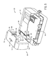
- FIG. 5 is an exploded perspective view of an embodiment of the meter 20 including optical components and the cover 70 having the light modifying feature 80 configured to alter an orientation of light by 180 degrees to facilitate detection of tampering events.
- the cover 70 is in an open position 84, and the cover 70 is configured to be mounted to the main body 72 in a direction of arrow 88.
- the cover 70 and/or the main body 72 may have any suitable shape, geometry, and/or configuration.
- the cover 70 may be rotated and/or pivoted with respect to the main body 72 to apply the cover 70 to the main body 72. In some such configurations, the cover 70 may be rotated about a central axis of the meter 20 or about a hinge of the meter 20, for example.
- the main body 72 includes a faceplate 90 that is configured to protect certain components of the meter 20, such as the circuit board 53.
- the faceplate 90 may be opaque to block visualization of certain components of the meter 20.
- the emitter 60 and the detector 62 may be coupled to the circuit board 53 in any suitable manner, and thus may also be protected by the faceplate 90.
- the emitter 60 and the detector 62 are positioned within a housing 92 that is coupled to (e.g., mounted on) the circuit board 53.
- the main body 72 and the cover 70 may be configured to facilitate alignment of the light modifying feature 80 with the emitter 60 and the detector 62 when the cover 70 is applied to the main body 72.
- one or more alignment guides e.g., protrusions and corresponding slots
- the faceplate 90 of the main body 72 may include an opening 94 configured to receive the light modifying feature 80 of the cover 70. In such cases, when the cover 70 is applied to the main body 72, the light modifying feature 80 extends through the opening 94 and is aligned with and positioned proximate to the emitter 60 and the detector 62.
- the light modifying feature 80 may have any suitable horizontal cross-sectional shape, such as rectangular or triangular, for example.
- the light modifying feature 80 may have a uniform horizontal cross-sectional shape along a length 96 of the light modifying feature 80.
- an end portion 98 of the light modifying feature 80 may include structural elements, such as one or more reflective surfaces or angled surfaces, to modify an orientation of light.
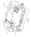
- FIG. 6 is a partial cutaway perspective view of an embodiment of the meter 20 of FIG. 5 with the cover 70 in a closed position 100 and having the end portion 98 of the light modifying feature 80 positioned proximate to the emitter 60 and the detector 62. While the cover 70 is in the closed position 100, the light emitted by the emitter 60 contacts the light modifying feature 80.
- the light modifying feature 80 includes structural elements configured to alter the orientation of emitted light by approximately 180 degrees.
- the structural elements may include diverging reflective surfaces (e.g., a v-shape structure or a diverging structure), as described in more detail below.
- diverging reflective surfaces e.g., a v-shape structure or a diverging structure
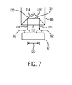
- FIG. 7 is a schematic side view of a portion of the meter 20 of FIGS. 5 and 6 with the cover 70 in the closed position 100.
- the light modifying feature 80 reflects the light emitted by the emitter 60 toward the detector 62, while the cover 70 is in the closed position 100.
- the emitter 60 and the detector 62 are positioned side-by-side or adjacent to each other.
- the light modifying feature 80 is a light reflecting feature (e.g., a prism or porro prism) having two reflecting faces 110, 112 (e.g. diverging reflecting surfaces or diverging reflectors) positioned at an angle 114 (e.g., 90 degrees) relative to each other.
- Light emitted by the emitter 60 travels along a first path 116 and contacts the first reflecting face 110.
- the light is reflected from the first reflecting face 110 along a second path 118 toward the second reflecting face 112.
- the second reflecting face 112 reflects the light along a third path 120, parallel to the first path 114, toward the detector 62.
- the light modifying feature 80 includes a bottom surface 119 positioned orthogonally with respect to the first path 116 and the second path 118, such that the light is not dispersed or altered by passing through the bottom surface 119.
- the emitted light may be totally internally reflected by the first and second reflective faces 110, 112 of the light modifying feature 80.
- the light modifying feature 80 may reflect the light through a total angle of 180 degrees, and the light reflected toward the detector 62 may be offset from the light emitted by the emitter 62 by a distance 122.
- the detector 62 may be positioned adjacent to the emitter 60 at the distance 122 from the emitter 60, as shown, and may detect the emitted light due to reflection of the light by the light modifying feature 80 while the cover 70 is in the closed position 100.
- the first and second reflective faces 110, 112 of the light modifying feature 80 may be configured to reflect the light through any suitable total angle (e.g., 60 to 120 degrees, 70 to 110 degrees, or 80 to 100 degrees) and the emitter 60 and the detector 62 may be positioned in appropriate positions to enable emission and detecting of the light for tamper detection, as disclosed herein.
- the light modifying feature 80 is not positioned proximate to the emitter 60 and the detector 62.
- the processor 46 may be configured to determine that the cover 70 has been removed from the meter 20 and that a tampering event has occurred based whether light is received at the detector 62. In some embodiments, an intensity of the light received at the detector 62 may be monitored.
- the processor 46 may be configured to determine that the tampering event has occurred when the intensity of the light received at the detector 62 is below a predetermined threshold intensity. When the tampering event is detected, the processor 46 may record the tampering event and/or may communicate the tampering event to a utility provider, as discussed above. In certain embodiments, other control actions may be taken, such as locking out the meter 20, terminating service of the utility, or the like.
- the meter 20 may not be able to draw power from an external source, such as the AC lines 26 ( FIG. 2 ), and may be powered by any suitable source such as solar power and/or the battery/super capacitor 34 ( FIG. 2 ).
- the meter 20 may be configured to draw power from the battery/super capacitor 34 only for certain processes, such as intermittent communications, maintaining the data stored within the nonvolatile storage 50, the memory 48, and/or the processor 46, and/or detecting tampering events.
- the meter 20 may be configured to adjust a frequency with which the emitter 60 emits light when the meter 20 is operating only with solar power or power from the battery/super capacitor 24 (e.g., emit light periodically, rather than continuously, or at less frequent time intervals) to prolong operation of the tamper-detection sensor 64 of the meter 20 in such circumstances.
- the meter 20 may have a normal tamper detection mode in which the emitter 60 emits light at a first frequency and the meter 20 may have a low power tamper detection mode (e.g., when powered by solar power and/or the battery/super capacitor 34) in which the emitter 60 emits light at a second frequency, less than the first frequency.
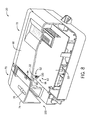
- FIG. 8 is a partial cutaway perspective view of an embodiment of the meter 20 having optical components and the light modifying feature 80 that is configured to alter an orientation of light by 90 degrees to detect tampering events.
- the emitter 60 and the detector 62 may be positioned in a crosswise configuration, such as perpendicular to one another, and may be coupled to the circuit board 53, or otherwise coupled to the main body 72 of the meter 20, in spaced-apart relation.
- the emitter 60 may be disposed within a first housing 130 and the detector 62 may be disposed within a second housing 132. As discussed above with respect to FIGS.
- the light modifying feature 80 may extend from the interior surface 82 of the top wall 74 of the cover 70, and the end portion 98 may be positioned proximate (e.g., near or adjacent) to the emitter 60 and the detector 62 while the cover 70 is in the closed position 100.
- the light modifying feature 80 may have any suitable cross-sectional area.
- the light modifying feature 80 may have a rectangular cross-sectional shape along a portion of its length 96 ( FIG. 4 ) and a triangular cross-sectional shape at the end portion 98.
- the light modifying feature 80 may have a generally uniform triangular or rectangular cross-section along its length 96.
- the cover 70 and the main body via the opening 94 for example, may be configured to align the light modifying feature 80 with the emitter 60 and the detector 62.
- the emitter 60 and the detector 62 are disposed in a crosswise configuration, and relative to the light modifying feature 80, in a configuration that enables the emitter 60 to emit light toward the light modifying feature 80 and that enables the detector 62 to detect the light reflected from the light modifying feature 80.
- FIG. 9 is a schematic top view of a portion of the meter 20 of FIG. 8 with the cover 70 in the closed position 100.
- the light modifying feature 80 is a prism having one reflective face 134 at an angle relative to both the emitter 60 and the detector 62.
- the emitter 60 is configured to emit light along a first path 136 toward the light modifying feature 80.
- the reflective face 134 reflects the light by an angle 137, which is about 90 degrees in the illustrated embodiment, and the reflected light travels toward the detector 62 along a second path 138.
- the light modifying feature 80 may have a triangular horizontal cross-section (e.g., a right triangular horizontal cross-section).
- a first wall 140 and a second wall 142 may be positioned orthogonally with respect to each other and with respect to the first path 136 and the second path 138, respectively, such that the light is not dispersed or altered by passing through the walls 140, 142.
- the emitter 60 and the detector 62 are positioned in a crosswise configuration (e.g., angled relative to one another). It should be understood that the emitter 60 and the detector 62 may be positioned at any suitable angle relative to one another, such as about 90 degrees, 60-120 degrees, 70-110 degrees, or 80-100 degrees. Additionally, the emitter 60, the detector 62, and the light modifying feature 80 are positioned to facilitate detection of the emitted light at the detector 62 while the cover 100 is in the closed position.
- the light modifying feature 80 is not positioned proximate to the emitter 60 and the detector 62. While the cover 70 is not in the closed position 100, light emitted by the emitter 60 is not reflected by the reflective face 134 toward the detector 62.
- the processor 46 may be configured to determine that the cover 70 has been removed from the meter 20 and that a tampering event has occurred based whether light is received at the detector 62.
- the processor 46 may record the tampering event and/or may communicate the tampering event to a utility provider, as discussed above. Other control actions, such as locking the meter 20, termination service, or the like, may be taken.
- the light modifying feature 80 shown in FIGS. 8 and 9 is configured to alter the orientation of light by 90 degrees
- the light modifying feature 80 may be configured to alter the orientation of light in any suitable manner or by any suitable degree.
- the light modifying feature 80 may alter the orientation of light by approximately 10-170 degrees, approximately 20-150 degrees, approximately 50-125 degrees, approximately 75-100 degrees, or any other suitable angle 137, such as about 45, 60, 75, 80, 105, 120, 135, 150, 165, or 180 degrees.
- the emitter 60, the detector 62, and the light modifying feature 80 are disposed relative to one another to facilitate reflection and subsequent detection of the emitted light at the detector 62 while the cover is in the closed position 100.
- FIG. 10 is a partial cutaway perspective view of an embodiment of the meter 20 having optical components and the cover 70 having the light modifying feature 80 configured to focus light to facilitate detection of tampering events.
- the light modifying feature 80 may have any suitable form for focusing light, such as a lens. Additionally, the light modifying feature 80 may be configured to enable light to pass through the light modifying feature 80 in one or more directions (e.g., may transmit or transfer light).
- the emitter 60 and the detector 62 may be positioned adjacent to one another and may be coupled to the circuit board 53. In some embodiments, the emitter 60 and the detector 62 are disposed within a housing 152 that is coupled to the circuit board 53. As discussed above with respect to FIG.
- the light modifying feature 80 may extend from the interior surface 82 of the top wall 74 of the cover 70.
- the light modifying feature 80 may be positioned between any suitable light reflective portion of the meter 20, such as a side wall 154 of the meter 20, and one or both of the emitter 60 and the detector 62.
- the side wall 154 may be opaque or may be otherwise configured to reflect light.
- the emitter 60, the detector 62, the light modifying feature 80, and the side wall 154 are disposed in a configuration that enables the emitter 60 to emit light through the light modifying feature 80 toward the side wall 154 and that enables the detector 62 to detect the light reflected by the side wall 154 and focused by the light modifying feature 80, as discussed in more detail below.
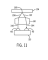
- FIG. 11 is a schematic top view of a portion of the meter 20 of FIG. 10 with the cover 70 is in the closed position 100.
- the emitter 60 and the detector 62 are positioned in a side-by-side configuration.
- the light emitted by the emitter 62 travels along a first path 156 toward the light modifying feature 80.
- the light modifying feature 80 may alter (e.g., focus) the direction or orientation of the light as the light passes through the light modifying feature 80.
- the light modifying feature 80 may direct the light along a second path 158 toward a location 160 (e.g., a light-reflective area) of the side wall 154.
- the light may be reflected by the side wall 154 and may travel along a third path 162 toward the light reflecting feature 80.
- the light reflecting feature 80 may again alter the direction or orientation of the light and may direct the light along a fourth path 164 toward the detector 62.
- the emitter 60, the detector 62, the light modifying feature 80, and/or the side wall 54 are positioned to facilitate detection of the emitted light at the detector 62 while the cover 100 is in the closed position.
- the light modifying feature 80 is not positioned proximate to the emitter 60 and the detector 62.
- the processor 46 may be configured to determine that the cover 70 has been removed from the meter 20 and that a tampering event has occurred based on whether light is received at the detector 62.
- the processor 46 may record the tampering event and/or may communicate the tampering event to a utility provider, as discussed above.
- FIG. 12 is a process flow diagram illustrating an embodiment of a method for detecting a tampering event in a utility meter, e.g., meter 20.
- FIG. 12 depicts an embodiment of a method 200 of operation of the meter 20.
- the method 200 may be a computer-implemented method, and each step of the method 200 may be carried out based on code or instructions stored in a non-transitory machine-readable medium (e.g., the non-volatile storage 50 or the memory 48) and executed, for example, by the one or more processors 46, for example.
- the method 200 may begin with emitting light via the emitter 60 (block 202). As noted above, the light may be of any suitable wavelength and may be emitted continuously or at predetermined intervals.
- the processor 46 may monitor whether the light is received at the detector 62 (block 204). For example, when light is received at the detector 62, the detector 62 may generate a signal that is transmitted to the processor 46. However, if no light is received at the detector 62, the detector 62 does not transmit the signal to the processor 46. In some cases, an intensity of the light received at the detector 62 may be monitored based on an intensity of the signal generated by the detector 62, for example. The processor 46 may determine whether a tampering event has occurred based on the light received at the detector 62 (block 206).
- the processor 46 may determine that the tampering event has occurred if no light is received at the detector 62, or if light corresponding to the wavelengths of light emitted by the emitter 60 is not received at the detector 62, for example. In some cases, the processor 46 may determine that the tampering event has occurred if the intensity of the light received at the detector 62 is below a predetermined threshold.
- the processor 46 may provide an indication that the tampering event has occurred (block 208).
- the acts represented by block 208 may include, by way of non-limiting examples, recording (e.g., storing) data relating to the cover removal (e.g., a date and/or time of the removal), communicating with the utility provider 12 that a tampering event has occurred, providing a visual indication of the tampering event via the display 44, triggering an alarm (e.g., a visual or audible alarm) at the meter 20 or other suitable location, or any combination thereof.
- recording e.g., storing
- data relating to the cover removal e.g., a date and/or time of the removal
- communicating with the utility provider 12 that a tampering event has occurred
- providing a visual indication of the tampering event via the display 44 triggering an alarm (e.g., a visual or audible alarm) at the meter 20 or other suitable location, or any combination thereof.
- the processor 46 may instruct the communication links 22 of the meter 20 to communicate with one or more external devices, such as external metering infrastructure, cellular telephones, personal computers, or similar devices, to name a few. Specifically, one or more indications that the meter 20 has detected a tampering event may be communicated to any one or a combination of these devices. The indications may include identifying information of the consumer and/or the meter 20, a time and/or date in which the potential tampering occurred, or any combination thereof. Further, in certain situations, the processor 46 may cause the display 44 to provide a brief (e.g., a few seconds) visual indication that a potential tampering situation has been detected.
- a brief e.g., a few seconds
- the display 44 may be locked into this indication, for example, until a technician or similar authorized person resets the meter 20 to normal operation.
- the display 44 may indicate "COVER REMOVAL DETECTED,” or "TAMPER DETECTED,” and, additionally or alternatively, may provide an indication of the date and/or time of the tampering event.
- the meter 20 may block other operation of the meter 20 or use of the metered utility until the tamper indication has been cleared from the meter 20, for example by resetting the meter 20 using an authorized code and/or authorized hardware.
- the utility service may be stopped until the tamper indication has been cleared from the meter 20, for example.
- a utility meter may be configured to detect removal of the cover using one or more optical components and a light modifying feature, and detection of cover removal may in turn be utilized to identify tampering events.
- the tamper detection systems disclosed herein may also be configured to initiate a suitable response or control action, such as providing an indication of the tampering event, locking the meter, or the like.
Landscapes
- Physics & Mathematics (AREA)
- General Physics & Mathematics (AREA)
- Fluid Mechanics (AREA)
- Photometry And Measurement Of Optical Pulse Characteristics (AREA)
- Measuring Volume Flow (AREA)
- Arrangements For Transmission Of Measured Signals (AREA)
Abstract
Description
- The subject matter disclosed herein relates to tamper detection in a utility meter.
- Utility meters that measure utility consumption may enable a utility provider, such as an electricity provider, to monitor a consumer's use of the utility. In some instances, utility meters are read manually, which can be costly, inefficient, and subject to errors. In some instances, utility providers may remotely monitor utility meters via a communications network. In such cases, a technician of the utility provider may physically access the utility meter to perform maintenance on the meter or to make adjustments to one or more operational parameters of the utility meter, for example. Thus, the utility meter may include a removable cover to facilitate physical access to the utility meter. Unfortunately, in certain situations, an unauthorized person may attempt to remove the cover to physically access the utility meter, in an attempt to alter utility consumption data or to restore the utility to a residence that has not paid for the utility, for example. Accordingly, certain utility meters may be subject to tampering or unauthorized use.
- A summary of certain embodiments disclosed herein is set forth below. It should be understood that these aspects are presented merely to provide the reader with a brief summary of these certain embodiments and that these aspects are not intended to limit the scope of this disclosure. Indeed, this disclosure may encompass a variety of aspects that may not be set forth below.
- In one embodiment, a utility meter includes a main body supporting metering circuitry configured to monitor consumption of a utility, an emitter configured to emit one or more wavelengths of light, and a detector configured to receive light and to generate a signal indicative of light received at the detector. The utility meter also includes a meter cover configured to be positioned relative to the main body. The meter cover includes a light modifying feature coupled to an interior surface of the meter cover. The light modifying feature is configured to alter an orientation of the emitted light and to direct the emitted light toward the detector while the meter cover is in a closed position relative to the main body. The utility meter also includes a processor configured to determine whether the meter cover is in the closed position or an open position based on the signal generated by the detector.
- In one embodiment, a system includes a tamper detection system for a utility meter. The tamper detection system includes an emitter configured to emit light and a detector configured to receive light. The tamper detection system also includes a light modifying feature configured to help direct the light along a path from the emitter to the detector while a meter cover is in a closed position relative to the utility meter, wherein the path is broken when the meter cover is in an open position relative to the utility meter.
- In one embodiment, a method for detecting tampering of a utility meter includes the steps of emitting light via an emitter coupled to the utility meter and altering an orientation of the light emitted by the emitter to direct the light toward a detector coupled to the utility meter via a light modifying feature coupled to a cover of the utility meter while the cover is in a closed position relative to the utility meter. The method also includes, using a processor of the utility meter, monitoring an intensity of the light received at the detector of the utility meter, comparing the intensity of the light received at the detector to a predetermined threshold intensity, and identifying a tampering event of the utility meter when the intensity of the light received at the detector is below the predetermined threshold.
- These and other features, aspects, and advantages of the present invention will become better understood when the following detailed description is read with reference to the accompanying drawings in which like characters represent like parts throughout the drawings, wherein:
-
FIG. 1 is a block diagram of an embodiment of an electrical system having energy meters configured to monitor power consumption and to detect tampering events; -
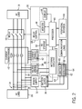
FIG. 2 is a block diagram of an embodiment of an energy meter configured to detect tampering events; -
FIG. 3 is a front view of an embodiment of the energy meter ofFIG. 2 ; -
FIG. 4 is a perspective view of an embodiment of a cover that may be used with the energy meter ofFIG. 2 ; -
FIG. 5 is an exploded perspective view of an embodiment of an energy meter including optical components and a cover having a light modifying feature configured to alter an orientation of light by 180 degrees to facilitate detection of tampering events; -
FIG. 6 is a partial cutaway perspective view of an embodiment of the energy meter of -
FIG. 5 with the cover in a closed position and the light modifying feature positioned proximate to the optical components; -
FIG. 7 is a schematic side view of a portion of the energy meter ofFIG. 5 with the cover in the closed position and the light modifying feature positioned proximate to the optical components; -
FIG. 8 is a perspective view of an embodiment of an energy meter including optical components and a cover having a light modifying feature configured to alter an orientation of light by 90 degrees to facilitate detection of tampering events; -
FIG. 9 is a schematic top view of a portion of the energy meter ofFIG. 8 with the cover in a closed position and the light modifying feature positioned proximate to the optical components; -
FIG. 10 is a perspective view of an embodiment of an energy meter including optical components and a cover having a light modifying feature configured to focus light to facilitate detection of tampering events; -
FIG. 11 is a schematic top view of a portion of the energy meter ofFIG. 10 with the cover in a closed position and the light modifying feature positioned proximate to the optical components; and -
FIG. 12 is a process flow diagram of an embodiment of a method for detecting a tampering event. - One or more specific embodiments of the present invention will be described below. In an effort to provide a concise description of these embodiments, all features of an actual implementation may not be described in the specification. It should be appreciated that in the development of any such actual implementation, as in any engineering or design project, numerous implementation-specific decisions must be made to achieve the developers' specific goals, such as compliance with system-related and business-related constraints, which may vary from one implementation to another. Moreover, it should be appreciated that such a development effort might be complex and time consuming, but would nevertheless be a routine undertaking of design, fabrication, and manufacture for those of ordinary skill having the benefit of this disclosure.
- When introducing elements of various embodiments of the present invention, the articles "a," "an," "the," and "said" are intended to mean that there are one or more of the elements. The terms "comprising," "including," and "having" are intended to be inclusive and mean that there may be additional elements other than the listed elements. Furthermore, any numerical examples in the following discussion are intended to be non-limiting, and thus additional numerical values, ranges, and percentages are within the scope of the disclosed embodiments.
- Certain utility meters may be subject to tampering by removing a cover of the utility meter to access control elements of the utility meter. Utility meters include energy meters, water meters, and sewage meters. Energy meters may include electric meters and gas meters, such as natural gas meters. Furthermore, the utility meters may include smart utility meters, as discussed below. The following discussion focuses on energy meters, such as an electric meter, as an example that may benefit from the disclosed tamper detection system, although the tamper detection system may be used in any of the utility meters. As noted above, an unauthorized user may remove the cover of an energy meter and attempt to restore electricity or change utility consumption data by manipulating certain control elements of the energy meter. Accordingly, disclosed herein are systems and methods configured to detect removal of the cover of the utility meter to detect a tampering event.
- The disclosed embodiments utilize optical techniques to detect removal of the cover, which may be a clear (e.g., transparent) cover, relative to the utility meter. Removal of the cover of the utility meter may be indicative of a tampering event. Without the disclosed embodiments, techniques for detecting cover removal and tampering events of utility meters may utilize switches or opaque, reflective components that are coupled to the transparent cover of the utility meter. Such techniques require physical contact between various parts (e.g., between the switch and meter circuitry or between the cover and the opaque components), and thus, are subject to damage during transport, drops, or other mechanical forces. Additionally, such techniques may block visibility of certain internal portions of the utility meter, may require additional parts, may have a more complex structure, and/or may have higher costs as compared with the embodiments disclosed herein.
- With the foregoing in mind, the present embodiments may include optical components (e.g., an emitter and a detector) positioned within the utility meter to facilitate detection of the tampering event. The emitter may be configured to emit one or more wavelengths of light and the detector may be configured to detect light. Light received at the detector may be monitored to determine whether the cover is suitably positioned on the utility meter. The cover of the utility meter may include a light modifying feature that is configured to direct the emitted light toward the detector while the cover is in a closed position (e.g., an on position) relative to the utility meter. For example, the light modifying feature may be a prism configured to reflect light toward the detector or a lens configured to focus light toward the detector. Therefore, while the emitted light is received at the detector, a processor associated with the utility meter may determine that the cover is in the closed position and is suitably positioned on the utility meter. However, while the emitted light is not received at the detector, or while an intensity of the light received at the detector is below a predetermined threshold intensity, the processor may determine that that the cover is in an open position (e.g., an off position) or is not suitably positioned on the utility meter, and therefore, that the tampering event has occurred. Upon determining that the tampering event has occurred, the processor may record the potential tampering event locally at the utility meter (e.g., in a nonvolatile memory) and/or may notify a utility provider (e.g., via a communications network) of the tampering event to enable the utility provider to take an appropriate action, for example.
- It should be noted that while the disclosed embodiments are discussed in the context of energy meters configured to detect tampering events, that other types of utilities are also presently contemplated. For example, as mentioned above, utility meters in accordance with the disclosed embodiments may monitor any one or a combination of electricity, heat, gas, water, or any other utility. Therefore, while the disclosed embodiments are presented in the context of tamper-detecting energy meters, other tamper-detecting utility meters, such as tamper-detecting heat meters, tamper-detecting gas meters, tamper-detecting water meters, or a combination thereof, are presently contemplated. Furthermore, energy meters, as presently discussed, may include gas meters, electricity meters, or a combination thereof.
- With the foregoing in mind,
FIG. 1 illustrates a block diagram of anelectrical system 10 including apower utility 12 that supplies power to apower grid 14. Loads on thepower grid 14 may include, for example, residential and/orcommercial establishments 16. Tamper-detectingenergy meters 20 may monitor the power consumption by theestablishments 16. As mentioned above and described in greater detail below, the tamper-detectingenergy meters 20 are configured to detect the removal of their respective covers to facilitate identification of tampering events. - In a normal operational state, the tamper-detecting
energy meters 20 may monitor power consumed by theestablishment 16 to which they are affixed. Additionally, the tamper-detectingenergy meters 20 may communicate with thepower utility 12 via data communication links 22, which may be part of a communications network. Suchdata communication links 22 may be wired (e.g., over wired telecommunication infrastructure) or wireless (e.g., a cellular network or other wireless broadband, such as WiMax). Similarly, thepower utility 12 may employ acommunication link 24 configured to communicate with the various tamper-detectingenergy meters 20. For example, the tamper-detectingenergy meters 20 may communicate data indicative of tampering events via the communication links 22. - As discussed in more detail below, the tamper-detecting
energy meters 20 may also be configured to detect tampering events in low power states, such as when electricity is not being provided to one or more of theestablishments 16 due to non-payment, a natural occurrence such as weather or seismic activity, or during manufacturing and transport of the tamper-detectingenergy meters 20 to the one ormore establishments 16. For example, in accordance with certain embodiments, the tamper-detectingenergy meters 20 may utilize any suitable source of power, such as solar power or battery power (i.e., electrical energy from an energy storage unit or battery) to maintain operation of certain components in a low power state (i.e., a no power state or base power state) of the tamper-detectingenergy meters 20. - The tamper-detecting
energy meters 20 may take any of a variety of forms. One embodiment of the tamper-detectingenergy meter 20 is illustrated inFIG. 2 . As shown, the tamper-detectingenergy meter 20 is joined to thepower grid 14. Power flows fromAC lines 26 to the one or more establishments 16 (e.g., an AC load). In the illustrated embodiment, the AC lines 26 may transmit power via one ormore phase lines 28 and aneutral line 30. The tamper-detectingenergy meter 20 may obtain power viapower supply circuitry 32 that may be coupled to the one ormore phase lines 28 and theneutral line 30 for the tamper-detecting energy meter's 20 internal power consumption. To backup power consumption data in the event of a power outage, for example, thepower supply circuitry 32 may also charge a battery and/or super capacitor 34 (i.e., an energy storage unit). In alternative embodiments, the backup power may be fed by a non-rechargeable battery. The battery/super capacitor 34 may also enable tamper detection in low power states by providing electrical energy to various elements of the tamper-detectingenergy meter 20, as discussed in detail below. -
Metering circuitry 36 may ascertain power consumption by monitoring the voltage and current traversing the AC lines 26 to the one ormore establishments 16. Current transformers (CTs) 40 andcurrent sensing circuitry 42 may determine the current flowing through the one or more phase lines 28. In some embodiments, themetering circuitry 36 may output the current power consumption values to anelectronic display 44, such as a liquid crystal display (LCD), and/or to aprocessor 46. Themetering circuitry 36 may sense the voltage and current inputs and send corresponding pulses to theprocessor 46, which calculates data, such as the energy accumulation, power factor, active power, reactive power, maximum demand, and the like. The data may be stored in amemory 48 and/or anonvolatile storage 50. - In some embodiments, the
processor 46 may also be configured to detect tampering events and/or to determine information related to the tampering events. Such information may be stored in the memory and/or thenonvolatile storage 50. For example, a time and/or date in which the cover of the tamper-detectingenergy meter 20 has been removed may be recorded and stored. As discussed below, a signal indicative of the tampering event and/or the information pertaining to the tampering event may be transmitted to the utility provider via the communications link 22, for example. The information may include, by way of non-limiting examples, a time and/or date of the tampering event, identification data of the tamper-detectingenergy meter 20, an identifier of a customer, GPS data, or any combination thereof. Although theprocessor 46 of the tamper-detectingenergy meter 20 may determine or identify tampering event, it should be understood that a separate processing unit (e.g., part of a separate monitoring or computer system) may be utilized to determine or identify the tampering event. For example, signals or the information may be provided to the separate processing unit via the communications link 22, for example, and the separate processing unit may process and/or analyze the signals to identify the tampering event. The separate processing unit may have processing features similar to those discussed with respect to theprocessor 46. - The
processor 46 may include one or more microprocessors, such as one or more "general-purpose" microprocessors, one or more application-specific processors (ASICs), a field programmable array (FPA) or a combination of such processing components, which may control the general operation of the tamper-detectingenergy meter 20. For example, theprocessor 46 may include one or more instruction set processors (e.g., RISC) and/or other related chipsets. Thememory 48 and/or thenonvolatile storage 50 may store the current and/or certain historical power consumption values, as well as provide instructions to enable theprocessor 46 to detect or determine occurrence of tampering events, determine information related to the tampering events, and to take certain actions based on the determination. - Programs or instructions executed by the
processor 46 to detect tampering events may be stored in any suitable component that includes one or more non-transitory, tangible, computer-readable media at least collectively storing the executed instructions or routines, such as, but not limited to, the memory devices and storage devices described below. Also, these programs encoded on such a computer program product may also include instructions that may be executed by theprocessor 46 to enable the tamper-detectingenergy meter 20 to provide various functionalities, such as communication with theutility provider 12 and/or a visual indication of the tampering event on thedisplay 44. - For example, instructions or data to be processed by the
processor 46 may be stored in thememory 48, which may include a volatile memory, such as random access memory (RAM); a non-volatile memory, such as read-only memory (ROM); or a combination of RAM and ROM devices, or may be stored internal to theprocessor 46 and/ormetering circuitry 36. Thememory 48 may store firmware for the tamper-detectingenergy meter 20, such as a basic input/output system (BIOS), an operating system, various programs, applications, or any other routines that may be executed on the tamper-detectingenergy meter 20, including user interface functions, processor functions, communication functions, image acquisition functions, audio alteration functions, media playback functions, and so forth. Thememory 48 may be optional if theprocessor 46 is capable of storing such information and/or firmware in its internal memory. As noted above, information pertaining to the tampering event, the tamper-detectingenergy meter 20, the customer, or any combination thereof, may also be provided to the utility provider. - As mentioned above, the tamper-detecting
energy meter 20 may communicate with thepower utility 12 to provide various data and information, including information related to tampering events. Such communication may take place via the one ormore communication links 22, which may include interfaces for a personal area network (PAN), such as a Bluetooth network, a local area network (LAN), such as an 802.11x Wi-Fi network, a wide area network (WAN), such as a 3G or 4G cellular network (e.g., WiMax), an infrared (IR) communication link, a Universal Serial Bus (USB) port, and/or a power line data transmission network such as Power Line Communication (PLC) or Power Line Carrier Communication (PLCC). Additionally, the tamper-detectingenergy meter 20 may connect to variousperipheral devices 56, such as computing devices (e.g., computers or portable phones) or input devices (e.g., a keyboard). - In certain embodiments, the
power utility 12 may communicate with the tamper-detectingenergy meter 20 to remotely control the flow of power to the one ormore establishments 16. Based on instructions received from thepower utility 12 via the communication links 22, theprocessor 46 may correspondingly instructrelay control circuitry 58 to open or close arelay 59. For example, if the consumer has not paid for the power being received, therelay 59 may be opened, disconnecting the one ormore establishments 16 from the AC lines 26. - The
nonvolatile storage 50 may be utilized for persistent storage of data and/or instructions relating to tamper detection. Thenonvolatile storage 50 may include flash memory, a hard drive, or any other optical, magnetic, and/or solid-state storage media. By way of non-limiting examples, thenonvolatile storage 50 may be used to store data files, such as historical power consumption as determined by themetering circuitry 36, as well as indications of consumer account balance information, dynamic power prices, tampering events, and/or abnormal activity on thepower grid 14 as communicated to the tamper-detectenergy meter 20 by thepower utility 12. For example, in certain embodiments, thenonvolatile storage 50 may store times and/or dates of tampering events. - As shown, the tamper-detecting
energy meter 20 includes anemitter 60 and adetector 62 communicatively coupled with theprocessor 46. Theemitter 60 may be configured to emit one or more wavelengths of light, and thedetector 62 may be configured to detect one or more wavelengths of light. In some embodiments, theemitter 62 may be a light emitting diode (LED) configured to emit any suitable wavelength of light, such as one or more wavelengths of infrared (IR) light. For example, in some embodiments, theemitter 60 may be configured to emit light between approximately 700 nm to 990 nm, between approximately 750 nm to 900 nm, or between approximately 800 nm to 850 nm. In some embodiments, theemitter 62 may be configured to emit light continuously. In certain embodiments, theemitter 62 may be configured to emit light periodically (e.g., at predetermined intervals, such as about every 1 minute, 5 minutes, 15 minutes, 60 minutes, or longer). Anysuitable detector 62 may be provided, and in some embodiments, thedetector 62 is a photodiode. In some embodiments, thedetector 62 may be tuned to detect the one or more wavelengths of light emitted by theemitter 62, and thus, may be configured to block detection of ambient light. - In some embodiments, the
emitter 60 and/or thedetector 62 may be coupled to and/or integrated into a circuit board 53 (e.g., a main meter assembly circuit board) that supports theprocessor 46, thedisplay 44, and/or other elements of the tamper-detectingenergy meter 20, such as themetering circuitry 36, theNV storage 50, thememory 48, one or more communication devices 54, variousperipheral devices 56, or any combination thereof, for example. In such cases, theemitter 60 and/or thedetector 62 may be positioned a suitable distance from reflective surfaces of the tamper-detecting utility meter 20 (e.g., opaque or reflective walls or the like). For example, theemitter 60 and/or thedetector 62 may be positioned at least approximately 2 millimeters (mm) to 7 mm away from reflective surfaces of the tamper-detectingutility meter 20. - Together, the
emitter 60 and thedetector 62 may form or be part of a tamper-detectingsensor 64. Theprocessor 46 may be configured to detect tampering events based on whether the light emitted by theemitter 60 is received at thedetector 62, which in turn may be an indication of whether the cover of the tamper-detectingenergy meter 20 is in a closed position or an open position, as discussed in more detail below. In some embodiments, an intensity of light received at thedetector 62 may be monitored, such as by theprocessor 46. In such cases, theprocessor 46 may be configured to detect tampering events when a change in the intensity of the light received at thedetector 62 exceeds a predetermined threshold percentage and/or when the intensity of the light received at the detector decreases below a predetermined threshold intensity. -
FIG. 3 is a front view of an embodiment of the tamper-detectingenergy meter 20, hereinafter "meter," having acover 70 and amain body 72. As shown, at least a portion of a top wall 74 (e.g., a front wall) of thecover 70 is substantially transparent to facilitate viewing various internal components of themeter 20, although in some embodiments, all of thecover 70 is transparent. Themeter 20 may have a generally rectangular geometry, although themeter 20, themain body 72, and/or thecover 70 may have any suitable shape or geometry, such as square, rectangular, triangular, circular, semi-circular, or elliptical. - As shown, the
cover 70 includes acover fastener 76, which is configured to couple thecover 70 to themain body 72. While anycover fastener 76 is presently contemplated, by way of non-limiting examples, thecover fastener 76 may couple thecover 70 to themain body 72 via a threaded fastener (e.g., a bolt or a screw), teeth, an interference fit, a friction fit, a snap fit (e.g., a tapered lip that engages a recess or an opening), a clamp, or any combination thereof. In the illustrated embodiment, thecover fastener 76 is positioned proximate to and is accessible at anexterior surface 77 of thetop wall 74, and thecover fastener 76 is a rotatable coupling using threads and/or an interference or friction fit, to provide resistance to removal of thecover 70 from themain body 72. Providing such resistance may be desirable to control the ease and speed with which a person may remove thecover 70 from themain body 72. -
FIG. 4 is a perspective view of thecover 70 that may be utilized with themeter 20 ofFIG. 2 . In the illustrated embodiment, thecover 70 includes thetop wall 74, which extends betweenopposed side walls 78 of thecover 70. Thecover 70 also includes alight modifying feature 80 to enable tamper detection as discussed in further detail below. Thelight modifying feature 80 may be part of or may form the tamper-detectingsensor 64, together with theemitter 60 and thedetector 62. Thelight modifying feature 80 may extend (e.g., protrude) from aninterior surface 82 of thetop wall 76 and may be positioned between the opposingside walls 78. In certain embodiments, thelight modifying feature 80 may extend orthogonally from thetop wall 70 and/or may be substantially parallel to the opposingside walls 78. - In certain embodiments, the
light modifying feature 80 may be integrally, gaplessly, and/or continuously formed with thecover 70. In certain embodiments, thecover 70 and thelight modifying feature 80 may be formed from a single, homogenous material (e.g., a one piece structure). For example, thecover 70 having thelight modifying feature 80 may be formed by molding the single, homogenous material into the desired configuration. Thus, in some embodiments, thelight modifying feature 80 is not physically-separate from thecover 70. In some embodiments, thecover 70 and thelight modifying feature 80 may have the same optical properties. For example, in certain embodiments, some or all of thecover 70 and/or some or all of thelight modifying feature 80 may be transparent. Themeter 20 in accordance with the present disclosure may therefore be configured to detect tampering events and may also have a generally low cost, simple, and/or sturdy configuration. -
FIG. 5 is an exploded perspective view of an embodiment of themeter 20 including optical components and thecover 70 having thelight modifying feature 80 configured to alter an orientation of light by 180 degrees to facilitate detection of tampering events. As shown, thecover 70 is in anopen position 84, and thecover 70 is configured to be mounted to themain body 72 in a direction ofarrow 88. As noted above, it should be understood that in other embodiments, thecover 70 and/or themain body 72 may have any suitable shape, geometry, and/or configuration. For example, in some embodiments, thecover 70 may be rotated and/or pivoted with respect to themain body 72 to apply thecover 70 to themain body 72. In some such configurations, thecover 70 may be rotated about a central axis of themeter 20 or about a hinge of themeter 20, for example. - As shown, the
main body 72 includes afaceplate 90 that is configured to protect certain components of themeter 20, such as thecircuit board 53. Thefaceplate 90 may be opaque to block visualization of certain components of themeter 20. In some embodiments, theemitter 60 and thedetector 62 may be coupled to thecircuit board 53 in any suitable manner, and thus may also be protected by thefaceplate 90. In the illustrated embodiment, theemitter 60 and thedetector 62 are positioned within ahousing 92 that is coupled to (e.g., mounted on) thecircuit board 53. - The
main body 72 and thecover 70 may be configured to facilitate alignment of thelight modifying feature 80 with theemitter 60 and thedetector 62 when thecover 70 is applied to themain body 72. For example, one or more alignment guides (e.g., protrusions and corresponding slots) may be provided on themain body 72 and/or thecover 70. By way of another example, thefaceplate 90 of themain body 72 may include anopening 94 configured to receive thelight modifying feature 80 of thecover 70. In such cases, when thecover 70 is applied to themain body 72, thelight modifying feature 80 extends through theopening 94 and is aligned with and positioned proximate to theemitter 60 and thedetector 62. Thelight modifying feature 80 may have any suitable horizontal cross-sectional shape, such as rectangular or triangular, for example. Thelight modifying feature 80 may have a uniform horizontal cross-sectional shape along alength 96 of thelight modifying feature 80. As discussed in more detail below, anend portion 98 of thelight modifying feature 80 may include structural elements, such as one or more reflective surfaces or angled surfaces, to modify an orientation of light. -
FIG. 6 is a partial cutaway perspective view of an embodiment of themeter 20 ofFIG. 5 with thecover 70 in aclosed position 100 and having theend portion 98 of thelight modifying feature 80 positioned proximate to theemitter 60 and thedetector 62. While thecover 70 is in theclosed position 100, the light emitted by theemitter 60 contacts thelight modifying feature 80. In the depicted embodiment, thelight modifying feature 80 includes structural elements configured to alter the orientation of emitted light by approximately 180 degrees. For example, the structural elements may include diverging reflective surfaces (e.g., a v-shape structure or a diverging structure), as described in more detail below. Thus, while the cover is in theclosed position 100, the emitted light is reflected by thelight modifying feature 80 toward thedetector 62 that is adjacent to theemitter 60. -
FIG. 7 is a schematic side view of a portion of themeter 20 ofFIGS. 5 and6 with thecover 70 in theclosed position 100. As shown, thelight modifying feature 80 reflects the light emitted by theemitter 60 toward thedetector 62, while thecover 70 is in theclosed position 100. In the depicted embodiment, theemitter 60 and thedetector 62 are positioned side-by-side or adjacent to each other. Additionally, thelight modifying feature 80 is a light reflecting feature (e.g., a prism or porro prism) having two reflecting faces 110, 112 (e.g. diverging reflecting surfaces or diverging reflectors) positioned at an angle 114 (e.g., 90 degrees) relative to each other. Light emitted by theemitter 60 travels along afirst path 116 and contacts the first reflecting face 110. The light is reflected from the first reflecting face 110 along asecond path 118 toward the second reflectingface 112. The second reflectingface 112 reflects the light along athird path 120, parallel to thefirst path 114, toward thedetector 62. In some embodiments, thelight modifying feature 80 includes abottom surface 119 positioned orthogonally with respect to thefirst path 116 and thesecond path 118, such that the light is not dispersed or altered by passing through thebottom surface 119. The emitted light may be totally internally reflected by the first and second reflective faces 110, 112 of thelight modifying feature 80. Thelight modifying feature 80 may reflect the light through a total angle of 180 degrees, and the light reflected toward thedetector 62 may be offset from the light emitted by theemitter 62 by adistance 122. Thus, thedetector 62 may be positioned adjacent to theemitter 60 at thedistance 122 from theemitter 60, as shown, and may detect the emitted light due to reflection of the light by thelight modifying feature 80 while thecover 70 is in theclosed position 100. In other embodiments, the first and second reflective faces 110, 112 of thelight modifying feature 80 may be configured to reflect the light through any suitable total angle (e.g., 60 to 120 degrees, 70 to 110 degrees, or 80 to 100 degrees) and theemitter 60 and thedetector 62 may be positioned in appropriate positions to enable emission and detecting of the light for tamper detection, as disclosed herein. - However, while the
cover 70 is not in the closed position 100 (e.g., thecover 70 is removed from the meter 20), thelight modifying feature 80 is not positioned proximate to theemitter 60 and thedetector 62. Thus, if thecover 70 is not in theclosed position 100, light emitted by theemitter 60 travels along thefirst path 116 and is not reflected by the reflective faces 110, 112 toward thedetector 62. Theprocessor 46 may be configured to determine that thecover 70 has been removed from themeter 20 and that a tampering event has occurred based whether light is received at thedetector 62. In some embodiments, an intensity of the light received at thedetector 62 may be monitored. In such cases, theprocessor 46 may be configured to determine that the tampering event has occurred when the intensity of the light received at thedetector 62 is below a predetermined threshold intensity. When the tampering event is detected, theprocessor 46 may record the tampering event and/or may communicate the tampering event to a utility provider, as discussed above. In certain embodiments, other control actions may be taken, such as locking out themeter 20, terminating service of the utility, or the like. - As noted above, in some circumstances, it may be desirable for the
meter 20 to continue to be able to detect tampering events even when power is not being provided to the one or more establishments 16 (e.g., due to a power outage). In such cases, themeter 20 may not be able to draw power from an external source, such as the AC lines 26 (FIG. 2 ), and may be powered by any suitable source such as solar power and/or the battery/super capacitor 34 (FIG. 2 ). Themeter 20 may be configured to draw power from the battery/super capacitor 34 only for certain processes, such as intermittent communications, maintaining the data stored within thenonvolatile storage 50, thememory 48, and/or theprocessor 46, and/or detecting tampering events. In some embodiments, themeter 20 may be configured to adjust a frequency with which theemitter 60 emits light when themeter 20 is operating only with solar power or power from the battery/super capacitor 24 (e.g., emit light periodically, rather than continuously, or at less frequent time intervals) to prolong operation of the tamper-detection sensor 64 of themeter 20 in such circumstances. Thus, themeter 20 may have a normal tamper detection mode in which theemitter 60 emits light at a first frequency and themeter 20 may have a low power tamper detection mode (e.g., when powered by solar power and/or the battery/super capacitor 34) in which theemitter 60 emits light at a second frequency, less than the first frequency. -
FIG. 8 is a partial cutaway perspective view of an embodiment of themeter 20 having optical components and thelight modifying feature 80 that is configured to alter an orientation of light by 90 degrees to detect tampering events. As shown, theemitter 60 and thedetector 62 may be positioned in a crosswise configuration, such as perpendicular to one another, and may be coupled to thecircuit board 53, or otherwise coupled to themain body 72 of themeter 20, in spaced-apart relation. In some such embodiments, theemitter 60 may be disposed within afirst housing 130 and thedetector 62 may be disposed within asecond housing 132. As discussed above with respect toFIGS. 3-6 , thelight modifying feature 80 may extend from theinterior surface 82 of thetop wall 74 of thecover 70, and theend portion 98 may be positioned proximate (e.g., near or adjacent) to theemitter 60 and thedetector 62 while thecover 70 is in theclosed position 100. As noted above, thelight modifying feature 80 may have any suitable cross-sectional area. As shown, thelight modifying feature 80 may have a rectangular cross-sectional shape along a portion of its length 96 (FIG. 4 ) and a triangular cross-sectional shape at theend portion 98. Although in other embodiments, thelight modifying feature 80 may have a generally uniform triangular or rectangular cross-section along itslength 96. Regardless of the cross-sectional shape of thelight modifying feature 80, thecover 70 and the main body, via theopening 94 for example, may be configured to align thelight modifying feature 80 with theemitter 60 and thedetector 62. Thus, theemitter 60 and thedetector 62 are disposed in a crosswise configuration, and relative to thelight modifying feature 80, in a configuration that enables theemitter 60 to emit light toward thelight modifying feature 80 and that enables thedetector 62 to detect the light reflected from thelight modifying feature 80. -
FIG. 9 is a schematic top view of a portion of themeter 20 ofFIG. 8 with thecover 70 in theclosed position 100. As shown, thelight modifying feature 80 is a prism having onereflective face 134 at an angle relative to both theemitter 60 and thedetector 62. Theemitter 60 is configured to emit light along afirst path 136 toward thelight modifying feature 80. Thereflective face 134 reflects the light by anangle 137, which is about 90 degrees in the illustrated embodiment, and the reflected light travels toward thedetector 62 along asecond path 138. Thelight modifying feature 80 may have a triangular horizontal cross-section (e.g., a right triangular horizontal cross-section). Afirst wall 140 and asecond wall 142 may be positioned orthogonally with respect to each other and with respect to thefirst path 136 and thesecond path 138, respectively, such that the light is not dispersed or altered by passing through thewalls emitter 60 and thedetector 62 are positioned in a crosswise configuration (e.g., angled relative to one another). It should be understood that theemitter 60 and thedetector 62 may be positioned at any suitable angle relative to one another, such as about 90 degrees, 60-120 degrees, 70-110 degrees, or 80-100 degrees. Additionally, theemitter 60, thedetector 62, and thelight modifying feature 80 are positioned to facilitate detection of the emitted light at thedetector 62 while thecover 100 is in the closed position. - As discussed above with respect to
FIG. 7 , if thecover 70 is not in the closed position 100 (e.g., thecover 70 is removed from the meter 20), thelight modifying feature 80 is not positioned proximate to theemitter 60 and thedetector 62. While thecover 70 is not in theclosed position 100, light emitted by theemitter 60 is not reflected by thereflective face 134 toward thedetector 62. Theprocessor 46 may be configured to determine that thecover 70 has been removed from themeter 20 and that a tampering event has occurred based whether light is received at thedetector 62. As noted above, when the tampering event is detected, theprocessor 46 may record the tampering event and/or may communicate the tampering event to a utility provider, as discussed above. Other control actions, such as locking themeter 20, termination service, or the like, may be taken. - Although the
light modifying feature 80 shown inFIGS. 8 and9 is configured to alter the orientation of light by 90 degrees, it should be understood that thelight modifying feature 80 may be configured to alter the orientation of light in any suitable manner or by any suitable degree. For example, thelight modifying feature 80 may alter the orientation of light by approximately 10-170 degrees, approximately 20-150 degrees, approximately 50-125 degrees, approximately 75-100 degrees, or any othersuitable angle 137, such as about 45, 60, 75, 80, 105, 120, 135, 150, 165, or 180 degrees. In such cases, theemitter 60, thedetector 62, and thelight modifying feature 80 are disposed relative to one another to facilitate reflection and subsequent detection of the emitted light at thedetector 62 while the cover is in theclosed position 100. -
FIG. 10 is a partial cutaway perspective view of an embodiment of themeter 20 having optical components and thecover 70 having thelight modifying feature 80 configured to focus light to facilitate detection of tampering events. Thelight modifying feature 80 may have any suitable form for focusing light, such as a lens. Additionally, thelight modifying feature 80 may be configured to enable light to pass through thelight modifying feature 80 in one or more directions (e.g., may transmit or transfer light). As shown, theemitter 60 and thedetector 62 may be positioned adjacent to one another and may be coupled to thecircuit board 53. In some embodiments, theemitter 60 and thedetector 62 are disposed within ahousing 152 that is coupled to thecircuit board 53. As discussed above with respect toFIG. 3 , thelight modifying feature 80 may extend from theinterior surface 82 of thetop wall 74 of thecover 70. Thelight modifying feature 80 may be positioned between any suitable light reflective portion of themeter 20, such as aside wall 154 of themeter 20, and one or both of theemitter 60 and thedetector 62. Theside wall 154 may be opaque or may be otherwise configured to reflect light. Theemitter 60, thedetector 62, thelight modifying feature 80, and theside wall 154 are disposed in a configuration that enables theemitter 60 to emit light through thelight modifying feature 80 toward theside wall 154 and that enables thedetector 62 to detect the light reflected by theside wall 154 and focused by thelight modifying feature 80, as discussed in more detail below. -
FIG. 11 is a schematic top view of a portion of themeter 20 ofFIG. 10 with thecover 70 is in theclosed position 100. As shown, theemitter 60 and thedetector 62 are positioned in a side-by-side configuration. The light emitted by theemitter 62 travels along afirst path 156 toward thelight modifying feature 80. Thelight modifying feature 80 may alter (e.g., focus) the direction or orientation of the light as the light passes through thelight modifying feature 80. Thelight modifying feature 80 may direct the light along asecond path 158 toward a location 160 (e.g., a light-reflective area) of theside wall 154. The light may be reflected by theside wall 154 and may travel along athird path 162 toward thelight reflecting feature 80. Thelight reflecting feature 80 may again alter the direction or orientation of the light and may direct the light along afourth path 164 toward thedetector 62. Thus, theemitter 60, thedetector 62, thelight modifying feature 80, and/or the side wall 54 are positioned to facilitate detection of the emitted light at thedetector 62 while thecover 100 is in the closed position. - As discussed above with respect to
FIGS. 7 and9 , if thecover 70 is not in the closed position 100 (e.g., thecover 70 is removed from the meter 20), thelight modifying feature 80 is not positioned proximate to theemitter 60 and thedetector 62. Thus, if thecover 70 is not in theclosed position 100, light emitted by theemitter 60 is not focused or otherwise altered by thelight modifying feature 80 to reach thedetector 62. Theprocessor 46 may be configured to determine that thecover 70 has been removed from themeter 20 and that a tampering event has occurred based on whether light is received at thedetector 62. As noted above, when the tampering event is detected, theprocessor 46 may record the tampering event and/or may communicate the tampering event to a utility provider, as discussed above. -
FIG. 12 is a process flow diagram illustrating an embodiment of a method for detecting a tampering event in a utility meter, e.g.,meter 20. Specifically,FIG. 12 depicts an embodiment of amethod 200 of operation of themeter 20. Themethod 200 may be a computer-implemented method, and each step of themethod 200 may be carried out based on code or instructions stored in a non-transitory machine-readable medium (e.g., thenon-volatile storage 50 or the memory 48) and executed, for example, by the one ormore processors 46, for example. Themethod 200 may begin with emitting light via the emitter 60 (block 202). As noted above, the light may be of any suitable wavelength and may be emitted continuously or at predetermined intervals. - The
processor 46 may monitor whether the light is received at the detector 62 (block 204). For example, when light is received at thedetector 62, thedetector 62 may generate a signal that is transmitted to theprocessor 46. However, if no light is received at thedetector 62, thedetector 62 does not transmit the signal to theprocessor 46. In some cases, an intensity of the light received at thedetector 62 may be monitored based on an intensity of the signal generated by thedetector 62, for example. Theprocessor 46 may determine whether a tampering event has occurred based on the light received at the detector 62 (block 206). Theprocessor 46 may determine that the tampering event has occurred if no light is received at thedetector 62, or if light corresponding to the wavelengths of light emitted by theemitter 60 is not received at thedetector 62, for example. In some cases, theprocessor 46 may determine that the tampering event has occurred if the intensity of the light received at thedetector 62 is below a predetermined threshold. - When the tampering event is detected, the
processor 46 may provide an indication that the tampering event has occurred (block 208). The acts represented byblock 208 may include, by way of non-limiting examples, recording (e.g., storing) data relating to the cover removal (e.g., a date and/or time of the removal), communicating with theutility provider 12 that a tampering event has occurred, providing a visual indication of the tampering event via thedisplay 44, triggering an alarm (e.g., a visual or audible alarm) at themeter 20 or other suitable location, or any combination thereof. Theprocessor 46 may instruct the communication links 22 of themeter 20 to communicate with one or more external devices, such as external metering infrastructure, cellular telephones, personal computers, or similar devices, to name a few. Specifically, one or more indications that themeter 20 has detected a tampering event may be communicated to any one or a combination of these devices. The indications may include identifying information of the consumer and/or themeter 20, a time and/or date in which the potential tampering occurred, or any combination thereof. Further, in certain situations, theprocessor 46 may cause thedisplay 44 to provide a brief (e.g., a few seconds) visual indication that a potential tampering situation has been detected. In some embodiments, thedisplay 44 may be locked into this indication, for example, until a technician or similar authorized person resets themeter 20 to normal operation. By way of a non-limiting example, in one embodiment, thedisplay 44 may indicate "COVER REMOVAL DETECTED," or "TAMPER DETECTED," and, additionally or alternatively, may provide an indication of the date and/or time of the tampering event. Further, in some embodiments, themeter 20 may block other operation of themeter 20 or use of the metered utility until the tamper indication has been cleared from themeter 20, for example by resetting themeter 20 using an authorized code and/or authorized hardware. In some embodiments, the utility service may be stopped until the tamper indication has been cleared from themeter 20, for example. - Technical effects of the presently disclosed embodiments include systems and methods to detect tampering events of utility meters. Particularly, a utility meter may be configured to detect removal of the cover using one or more optical components and a light modifying feature, and detection of cover removal may in turn be utilized to identify tampering events. The tamper detection systems disclosed herein may also be configured to initiate a suitable response or control action, such as providing an indication of the tampering event, locking the meter, or the like.
- This written description uses examples to disclose the invention, including the best mode, and also to enable any person skilled in the art to practice the invention, including making and using any devices or systems and performing any incorporated methods. The patentable scope of the invention is defined by the claims, and may include other examples that occur to those skilled in the art. Such other examples are intended to be within the scope of the claims if they have structural elements that do not differ from the literal language of the claims, or if they include equivalent structural elements with insubstantial differences from the literal languages of the claims.
Claims (15)
- A utility meter (20), comprising:a main body (72) supporting:metering circuitry (36) configured to monitor consumption of a utility;an emitter (60) configured to emit one or more wavelengths of light; anda detector (62) configured to receive light and to generate a signal indicative of light received at the detector;a meter cover (70) configured to be positioned relative to the main body (72), wherein the meter cover comprises a light modifying feature (80) coupled to an interior surface (82) of the meter cover (70), wherein the light modifying feature (80) is configured to alter an orientation of the emitted light and to direct the emitted light toward the detector (62) while the meter cover (70) is in a closed position relative to the main body (72); anda processor (46) configured to determine whether the meter cover (70) is in the closed position (100) or in an open position based on the signal generated by the detector (62).
- The utility meter of claim 1, wherein the light modifying feature (80) comprises a prism.
- The utility meter of claim 1 or 2, wherein the emitter (60) and the detector (62) are positioned adjacent to one another and the emitter (60) is configured to emit light in a first direction along a first pathway (116), and the detector (62) is configured to receive light traveling in a second direction, opposite the first direction, along a second pathway (120).
- The utility meter of claim 2 or 3, wherein the prism comprises first and second reflective surfaces (110,112) configured to reflect the light through a total angle of approximately 180 degrees.
- The utility meter of claim 2, wherein the prism comprises a reflective surface (134) configured to reflect the light through a total angle of approximately 90 degrees.
- The utility meter of claim 2 or 3, wherein the emitter (60) and the detector (62) are offset from one another, the emitter (60) is configured to emit light in a first direction along a first pathway (136), the detector (62) is configured to receive light traveling in a second direction along a second pathway (138) that is crosswise or angled relative to the first pathway (136).
- The utility meter of claim 1, wherein the light modifying feature (80) comprises a lens configured to be positioned between a reflective surface (154) of the utility meter (20) and both of the emitter (60) and the detector (62) while the cover (70) is in the closed position (100).
- The utility meter of claim 7, wherein the light modifying feature (80) is configured to focus the emitted light toward a location (160) on the reflective surface (154) of the utility meter (20).
- The utility meter of claim 8, wherein the reflective surface (154) is configured to reflect the light toward the lens (80), and the lens is configured to direct the light reflected from the reflective surface (154) toward the detector (62).
- The utility meter of any preceding claim, wherein the light modifying feature (80) and the meter cover (72) are integrally formed from a single, homogenous, transparent material.
- The utility meter of any preceding claim, wherein the emitter (60) is configured to emit infrared light.
- The system of any preceding claim, wherein the light modifying feature is transparent.
- A method for detecting tampering of a utility meter (20), comprising:emitting light via an emitter (60) coupled to the utility meter (20);altering an orientation of the light emitted by the emitter (60) to direct the light toward a detector (62) coupled to the utility meter (20) via a light modifying feature (80) coupled to a cover (70) of the utility meter (20) while the cover (70) is in a closed position relative to the utility meter (20);monitoring an intensity of the light received at the detector (62) of the utility meter (20), using a processor (46) of the utility meter (20);comparing the intensity of the light received at the detector (62) to a predetermined threshold intensity, using the processor (46) of the utility meter (20); andidentifying a tampering event of the utility meter (20) when the intensity of the light received at the detector (62) is below the predetermined threshold intensity, using the processor (46) of the utility meter (20) or using a separate processing unit.
- The method of claim 13, comprising emitting infrared light via the emitter.
- The method of claim 13 or 14, comprising storing information related to the tampering event at a memory (50) of the utility meter (20) or providing an indication of the tampering event to a remote utility provider via a communication link (22).
Applications Claiming Priority (1)
| Application Number | Priority Date | Filing Date | Title |
|---|---|---|---|
| US14/175,833 US9435665B2 (en) | 2014-02-07 | 2014-02-07 | System and method for tamper detection in a utility meter |
Publications (2)
| Publication Number | Publication Date |
|---|---|
| EP2905585A1 true EP2905585A1 (en) | 2015-08-12 |
| EP2905585B1 EP2905585B1 (en) | 2021-07-28 |
Family
ID=52446322
Family Applications (1)
| Application Number | Title | Priority Date | Filing Date |
|---|---|---|---|
| EP15154219.8A Active EP2905585B1 (en) | 2014-02-07 | 2015-02-06 | System and method for tamper detection in a utility meter |
Country Status (7)
| Country | Link |
|---|---|
| US (1) | US9435665B2 (en) |
| EP (1) | EP2905585B1 (en) |
| JP (2) | JP6703807B2 (en) |
| AU (1) | AU2015200482B2 (en) |
| CA (1) | CA2881256C (en) |
| ES (1) | ES2900348T3 (en) |
| ZA (1) | ZA201500761B (en) |
Cited By (2)
| Publication number | Priority date | Publication date | Assignee | Title |
|---|---|---|---|---|
| GB2541640A (en) * | 2015-05-26 | 2017-03-01 | Secure Int Holdings Pte Ltd | Utility meter |
| EP4567762A1 (en) * | 2023-12-04 | 2025-06-11 | Schneider Electric Industries Sas | Detection apparatus for detecting open state of box cover and device box |
Families Citing this family (5)
| Publication number | Priority date | Publication date | Assignee | Title |
|---|---|---|---|---|
| JP2020071496A (en) * | 2018-10-29 | 2020-05-07 | ソニー株式会社 | Information terminal, information processing device, and program |
| MX2021007388A (en) | 2018-12-18 | 2021-12-10 | Aclara Tech Llc | VERY LOW POWER POLLUTANT DETECTION CIRCUIT. |
| GB2618153A (en) * | 2022-04-29 | 2023-11-01 | Deer Tech Limited | A device |
| AU2023353082A1 (en) | 2022-09-28 | 2025-04-10 | Cresconet, Llc | Power management systems, devices, and methods |
| FR3149695A1 (en) * | 2023-06-07 | 2024-12-13 | Sagemcom Energy & Telecom Sas | Optical detection of the opening of a case |
Citations (4)
| Publication number | Priority date | Publication date | Assignee | Title |
|---|---|---|---|---|
| US4246489A (en) * | 1979-04-16 | 1981-01-20 | Tokyo Shibaura Electric Co., Ltd. | Liquid level detector for detecting a liquid level when reaching a prescribed height |
| US5216246A (en) * | 1992-02-03 | 1993-06-01 | Xerox Corporation | Optical safety shutoff for machine cover |
| WO1999035471A1 (en) * | 1998-01-09 | 1999-07-15 | Scully Signal Company | Fluid overfill probe with anti-reflective guard |
| US20100148982A1 (en) * | 2006-12-28 | 2010-06-17 | Rosemount Inc. | Proximity sensor system for industrial process transmitter |
Family Cites Families (15)
| Publication number | Priority date | Publication date | Assignee | Title |
|---|---|---|---|---|
| US4751396A (en) | 1986-03-10 | 1988-06-14 | Electronic Key Inc. | Infra-red security system |
| US5534708A (en) * | 1993-12-15 | 1996-07-09 | Simmonds Precision Products Inc. | Optical fuel/air/water sensor and detector circuit |
| US5399876A (en) * | 1994-03-03 | 1995-03-21 | Simmonds Precision Products, Inc. | Optical point level sensor with lens |
| CA2199927A1 (en) * | 1996-03-13 | 1997-09-13 | Simmonds Precision Products, Inc. | Self testing optical liquid level sensor |
| US6038050A (en) * | 1997-05-08 | 2000-03-14 | Hamar Laser Instruments, Inc. | Rotating laser scanner head with target mounted therein and system and method for use therewith |
| US6515294B1 (en) * | 1999-03-09 | 2003-02-04 | Pruftechnik Dieter Busch, Ag | Device for precision alignment of shafts, rollers, axles, spindles or machine tools |
| JP4686699B2 (en) | 2001-09-26 | 2011-05-25 | オプテックス株式会社 | Security sensor device |
| CN100505845C (en) * | 2004-02-05 | 2009-06-24 | 松下电器产业株式会社 | Television receiver and electronic equipment |
| US7786457B2 (en) * | 2006-06-28 | 2010-08-31 | Alcon, Inc. | Systems and methods of non-invasive level sensing for a surgical cassette |
| US7491926B1 (en) | 2007-07-25 | 2009-02-17 | Bosch Security Systems, Inc. | Offset optical security sensor for a door |
| US8319638B2 (en) | 2007-11-14 | 2012-11-27 | Honeywell International Inc. | Motion detector for detecting tampering and method for detecting tampering |
| TWI403979B (en) * | 2009-04-28 | 2013-08-01 | Int Currency Tech | An apparatus for detecting a foreign object in a bill passageway |
| US8688407B2 (en) | 2010-11-18 | 2014-04-01 | General Electric Company | Method, device and computer program product for magnetic tamper detection in a meter |
| US20130076340A1 (en) | 2011-09-23 | 2013-03-28 | General Electric Company | Reed switch chain to detect meter tampering |
| WO2013118257A1 (en) * | 2012-02-08 | 2013-08-15 | 三菱電機株式会社 | Electronic power meter |
-
2014
- 2014-02-07 US US14/175,833 patent/US9435665B2/en active Active
-
2015
- 2015-02-02 AU AU2015200482A patent/AU2015200482B2/en active Active
- 2015-02-02 ZA ZA2015/00761A patent/ZA201500761B/en unknown
- 2015-02-04 JP JP2015019820A patent/JP6703807B2/en active Active
- 2015-02-05 CA CA2881256A patent/CA2881256C/en active Active
- 2015-02-06 EP EP15154219.8A patent/EP2905585B1/en active Active
- 2015-02-06 ES ES15154219T patent/ES2900348T3/en active Active
-
2020
- 2020-05-11 JP JP2020083062A patent/JP6992118B2/en active Active
Patent Citations (4)
| Publication number | Priority date | Publication date | Assignee | Title |
|---|---|---|---|---|
| US4246489A (en) * | 1979-04-16 | 1981-01-20 | Tokyo Shibaura Electric Co., Ltd. | Liquid level detector for detecting a liquid level when reaching a prescribed height |
| US5216246A (en) * | 1992-02-03 | 1993-06-01 | Xerox Corporation | Optical safety shutoff for machine cover |
| WO1999035471A1 (en) * | 1998-01-09 | 1999-07-15 | Scully Signal Company | Fluid overfill probe with anti-reflective guard |
| US20100148982A1 (en) * | 2006-12-28 | 2010-06-17 | Rosemount Inc. | Proximity sensor system for industrial process transmitter |
Cited By (5)
| Publication number | Priority date | Publication date | Assignee | Title |
|---|---|---|---|---|
| GB2541640A (en) * | 2015-05-26 | 2017-03-01 | Secure Int Holdings Pte Ltd | Utility meter |
| GB2541640B (en) * | 2015-05-26 | 2020-06-10 | Secure Int Holdings Pte Ltd | Utility meter |
| GB2581280A (en) * | 2015-05-26 | 2020-08-12 | Secure Int Holdings Pte Ltd | Utility meter |
| GB2581280B (en) * | 2015-05-26 | 2021-03-17 | Secure Int Holdings Pte Ltd | Utility meter |
| EP4567762A1 (en) * | 2023-12-04 | 2025-06-11 | Schneider Electric Industries Sas | Detection apparatus for detecting open state of box cover and device box |
Also Published As
| Publication number | Publication date |
|---|---|
| JP6703807B2 (en) | 2020-06-03 |
| JP6992118B2 (en) | 2022-01-13 |
| US20150226583A1 (en) | 2015-08-13 |
| ZA201500761B (en) | 2017-08-30 |
| JP2020144902A (en) | 2020-09-10 |
| CA2881256A1 (en) | 2015-08-07 |
| EP2905585B1 (en) | 2021-07-28 |
| JP2015149069A (en) | 2015-08-20 |
| AU2015200482A1 (en) | 2015-08-27 |
| CA2881256C (en) | 2022-08-30 |
| AU2015200482B2 (en) | 2019-01-17 |
| US9435665B2 (en) | 2016-09-06 |
| ES2900348T3 (en) | 2022-03-16 |
Similar Documents
| Publication | Publication Date | Title |
|---|---|---|
| EP2905585B1 (en) | System and method for tamper detection in a utility meter | |
| US8754634B2 (en) | System and method for tamper detection in a utility meter | |
| JP5842120B2 (en) | Power usage monitoring device, power usage monitoring system | |
| US10458970B2 (en) | Method and apparatus for detecting contaminants in water | |
| US7106044B1 (en) | Systems, methods, and apparatuses for detecting residential electricity theft in firmware | |
| US7936163B2 (en) | Method and system for detecting electricity theft | |
| KR102163022B1 (en) | Remote water meter reading system | |
| KR102296295B1 (en) | Digital water meter and digital water meter management system with remote meter reading function | |
| EP4212885B1 (en) | Optical voltage sensing for underground medium voltage wires | |
| KR100937257B1 (en) | Telemetering information identifing system using wire and wireless telecommunication technology | |
| KR20170014741A (en) | Smart plug in intelligent transportation system and transportation apparauts management server | |
| US10459026B2 (en) | Damage preventing identification system for conductors and coupling points in electrical systems with data acquisition | |
| WO2009019717A1 (en) | Intelligent cathodic protection system (icap) | |
| KR102341042B1 (en) | A method and system for monitoring a movable asset using a monitoring device | |
| AU2019325340B2 (en) | System, method, and computer program product for wake up of a water meter | |
| Paul et al. | IoT based Energy Analyzer and Tampering Detection System for Smart Grid Applications | |
| KR102297336B1 (en) | A method and system for monitoring a movable asset using a monitoring device | |
| CZ308290B6 (en) | System for wireless data transmission from meters | |
| WO2012123790A1 (en) | An electricity supply management system and method therefor | |
| Pushpalatha et al. | AI-Assisted IoT System for Real-Time Electricity Theft | |
| Vani et al. | Power Theft Detection in Distribution Lines | |
| Mpiima | Domestic power theft monitoring system. | |
| WO2017060831A1 (en) | Automatic power monitor device and method | |
| Amin | An evaluation of the smart metering program | |
| BRPI1001816A2 (en) | electromechanical device connector for cutting |
Legal Events
| Date | Code | Title | Description |
|---|---|---|---|
| PUAI | Public reference made under article 153(3) epc to a published international application that has entered the european phase |
Free format text: ORIGINAL CODE: 0009012 |
|
| AK | Designated contracting states |
Kind code of ref document: A1 Designated state(s): AL AT BE BG CH CY CZ DE DK EE ES FI FR GB GR HR HU IE IS IT LI LT LU LV MC MK MT NL NO PL PT RO RS SE SI SK SM TR |
|
| AX | Request for extension of the european patent |
Extension state: BA ME |
|
| 17P | Request for examination filed |
Effective date: 20160212 |
|
| RBV | Designated contracting states (corrected) |
Designated state(s): AL AT BE BG CH CY CZ DE DK EE ES FI FR GB GR HR HU IE IS IT LI LT LU LV MC MK MT NL NO PL PT RO RS SE SI SK SM TR |
|
| RAP1 | Party data changed (applicant data changed or rights of an application transferred) |
Owner name: ACLARA METERS LLC |
|
| GRAP | Despatch of communication of intention to grant a patent |
Free format text: ORIGINAL CODE: EPIDOSNIGR1 |
|
| STAA | Information on the status of an ep patent application or granted ep patent |
Free format text: STATUS: GRANT OF PATENT IS INTENDED |
|
| INTG | Intention to grant announced |
Effective date: 20210209 |
|
| GRAS | Grant fee paid |
Free format text: ORIGINAL CODE: EPIDOSNIGR3 |
|
| GRAA | (expected) grant |
Free format text: ORIGINAL CODE: 0009210 |
|
| STAA | Information on the status of an ep patent application or granted ep patent |
Free format text: STATUS: THE PATENT HAS BEEN GRANTED |
|
| AK | Designated contracting states |
Kind code of ref document: B1 Designated state(s): AL AT BE BG CH CY CZ DE DK EE ES FI FR GB GR HR HU IE IS IT LI LT LU LV MC MK MT NL NO PL PT RO RS SE SI SK SM TR |
|
| REG | Reference to a national code |
Ref country code: GB Ref legal event code: FG4D |
|
| REG | Reference to a national code |
Ref country code: CH Ref legal event code: EP |
|
| REG | Reference to a national code |
Ref country code: AT Ref legal event code: REF Ref document number: 1415101 Country of ref document: AT Kind code of ref document: T Effective date: 20210815 |
|
| REG | Reference to a national code |
Ref country code: IE Ref legal event code: FG4D |
|
| REG | Reference to a national code |
Ref country code: DE Ref legal event code: R096 Ref document number: 602015071628 Country of ref document: DE |
|
| REG | Reference to a national code |
Ref country code: LT Ref legal event code: MG9D |
|
| REG | Reference to a national code |
Ref country code: NL Ref legal event code: MP Effective date: 20210728 |
|
| REG | Reference to a national code |
Ref country code: AT Ref legal event code: MK05 Ref document number: 1415101 Country of ref document: AT Kind code of ref document: T Effective date: 20210728 |
|
| PG25 | Lapsed in a contracting state [announced via postgrant information from national office to epo] |
Ref country code: FI Free format text: LAPSE BECAUSE OF FAILURE TO SUBMIT A TRANSLATION OF THE DESCRIPTION OR TO PAY THE FEE WITHIN THE PRESCRIBED TIME-LIMIT Effective date: 20210728 Ref country code: NO Free format text: LAPSE BECAUSE OF FAILURE TO SUBMIT A TRANSLATION OF THE DESCRIPTION OR TO PAY THE FEE WITHIN THE PRESCRIBED TIME-LIMIT Effective date: 20211028 Ref country code: NL Free format text: LAPSE BECAUSE OF FAILURE TO SUBMIT A TRANSLATION OF THE DESCRIPTION OR TO PAY THE FEE WITHIN THE PRESCRIBED TIME-LIMIT Effective date: 20210728 Ref country code: PT Free format text: LAPSE BECAUSE OF FAILURE TO SUBMIT A TRANSLATION OF THE DESCRIPTION OR TO PAY THE FEE WITHIN THE PRESCRIBED TIME-LIMIT Effective date: 20211129 Ref country code: LT Free format text: LAPSE BECAUSE OF FAILURE TO SUBMIT A TRANSLATION OF THE DESCRIPTION OR TO PAY THE FEE WITHIN THE PRESCRIBED TIME-LIMIT Effective date: 20210728 Ref country code: AT Free format text: LAPSE BECAUSE OF FAILURE TO SUBMIT A TRANSLATION OF THE DESCRIPTION OR TO PAY THE FEE WITHIN THE PRESCRIBED TIME-LIMIT Effective date: 20210728 Ref country code: BG Free format text: LAPSE BECAUSE OF FAILURE TO SUBMIT A TRANSLATION OF THE DESCRIPTION OR TO PAY THE FEE WITHIN THE PRESCRIBED TIME-LIMIT Effective date: 20211028 Ref country code: RS Free format text: LAPSE BECAUSE OF FAILURE TO SUBMIT A TRANSLATION OF THE DESCRIPTION OR TO PAY THE FEE WITHIN THE PRESCRIBED TIME-LIMIT Effective date: 20210728 Ref country code: SE Free format text: LAPSE BECAUSE OF FAILURE TO SUBMIT A TRANSLATION OF THE DESCRIPTION OR TO PAY THE FEE WITHIN THE PRESCRIBED TIME-LIMIT Effective date: 20210728 Ref country code: HR Free format text: LAPSE BECAUSE OF FAILURE TO SUBMIT A TRANSLATION OF THE DESCRIPTION OR TO PAY THE FEE WITHIN THE PRESCRIBED TIME-LIMIT Effective date: 20210728 |
|
| PG25 | Lapsed in a contracting state [announced via postgrant information from national office to epo] |
Ref country code: PL Free format text: LAPSE BECAUSE OF FAILURE TO SUBMIT A TRANSLATION OF THE DESCRIPTION OR TO PAY THE FEE WITHIN THE PRESCRIBED TIME-LIMIT Effective date: 20210728 Ref country code: LV Free format text: LAPSE BECAUSE OF FAILURE TO SUBMIT A TRANSLATION OF THE DESCRIPTION OR TO PAY THE FEE WITHIN THE PRESCRIBED TIME-LIMIT Effective date: 20210728 Ref country code: GR Free format text: LAPSE BECAUSE OF FAILURE TO SUBMIT A TRANSLATION OF THE DESCRIPTION OR TO PAY THE FEE WITHIN THE PRESCRIBED TIME-LIMIT Effective date: 20211029 |
|
| REG | Reference to a national code |
Ref country code: ES Ref legal event code: FG2A Ref document number: 2900348 Country of ref document: ES Kind code of ref document: T3 Effective date: 20220316 |
|
| PG25 | Lapsed in a contracting state [announced via postgrant information from national office to epo] |
Ref country code: DK Free format text: LAPSE BECAUSE OF FAILURE TO SUBMIT A TRANSLATION OF THE DESCRIPTION OR TO PAY THE FEE WITHIN THE PRESCRIBED TIME-LIMIT Effective date: 20210728 |
|
| REG | Reference to a national code |
Ref country code: DE Ref legal event code: R097 Ref document number: 602015071628 Country of ref document: DE |
|
| PG25 | Lapsed in a contracting state [announced via postgrant information from national office to epo] |
Ref country code: SM Free format text: LAPSE BECAUSE OF FAILURE TO SUBMIT A TRANSLATION OF THE DESCRIPTION OR TO PAY THE FEE WITHIN THE PRESCRIBED TIME-LIMIT Effective date: 20210728 Ref country code: SK Free format text: LAPSE BECAUSE OF FAILURE TO SUBMIT A TRANSLATION OF THE DESCRIPTION OR TO PAY THE FEE WITHIN THE PRESCRIBED TIME-LIMIT Effective date: 20210728 Ref country code: RO Free format text: LAPSE BECAUSE OF FAILURE TO SUBMIT A TRANSLATION OF THE DESCRIPTION OR TO PAY THE FEE WITHIN THE PRESCRIBED TIME-LIMIT Effective date: 20210728 Ref country code: EE Free format text: LAPSE BECAUSE OF FAILURE TO SUBMIT A TRANSLATION OF THE DESCRIPTION OR TO PAY THE FEE WITHIN THE PRESCRIBED TIME-LIMIT Effective date: 20210728 Ref country code: CZ Free format text: LAPSE BECAUSE OF FAILURE TO SUBMIT A TRANSLATION OF THE DESCRIPTION OR TO PAY THE FEE WITHIN THE PRESCRIBED TIME-LIMIT Effective date: 20210728 Ref country code: AL Free format text: LAPSE BECAUSE OF FAILURE TO SUBMIT A TRANSLATION OF THE DESCRIPTION OR TO PAY THE FEE WITHIN THE PRESCRIBED TIME-LIMIT Effective date: 20210728 |
|
| PLBE | No opposition filed within time limit |
Free format text: ORIGINAL CODE: 0009261 |
|
| STAA | Information on the status of an ep patent application or granted ep patent |
Free format text: STATUS: NO OPPOSITION FILED WITHIN TIME LIMIT |
|
| 26N | No opposition filed |
Effective date: 20220429 |
|
| PG25 | Lapsed in a contracting state [announced via postgrant information from national office to epo] |
Ref country code: IT Free format text: LAPSE BECAUSE OF FAILURE TO SUBMIT A TRANSLATION OF THE DESCRIPTION OR TO PAY THE FEE WITHIN THE PRESCRIBED TIME-LIMIT Effective date: 20210728 |
|
| PG25 | Lapsed in a contracting state [announced via postgrant information from national office to epo] |
Ref country code: MC Free format text: LAPSE BECAUSE OF FAILURE TO SUBMIT A TRANSLATION OF THE DESCRIPTION OR TO PAY THE FEE WITHIN THE PRESCRIBED TIME-LIMIT Effective date: 20210728 |
|
| REG | Reference to a national code |
Ref country code: CH Ref legal event code: PL |
|
| REG | Reference to a national code |
Ref country code: BE Ref legal event code: MM Effective date: 20220228 |
|
| PG25 | Lapsed in a contracting state [announced via postgrant information from national office to epo] |
Ref country code: LU Free format text: LAPSE BECAUSE OF NON-PAYMENT OF DUE FEES Effective date: 20220206 |
|
| PG25 | Lapsed in a contracting state [announced via postgrant information from national office to epo] |
Ref country code: LI Free format text: LAPSE BECAUSE OF NON-PAYMENT OF DUE FEES Effective date: 20220228 Ref country code: IE Free format text: LAPSE BECAUSE OF NON-PAYMENT OF DUE FEES Effective date: 20220206 Ref country code: CH Free format text: LAPSE BECAUSE OF NON-PAYMENT OF DUE FEES Effective date: 20220228 |
|
| PG25 | Lapsed in a contracting state [announced via postgrant information from national office to epo] |
Ref country code: BE Free format text: LAPSE BECAUSE OF NON-PAYMENT OF DUE FEES Effective date: 20220228 |
|
| P01 | Opt-out of the competence of the unified patent court (upc) registered |
Effective date: 20230608 |
|
| PG25 | Lapsed in a contracting state [announced via postgrant information from national office to epo] |
Ref country code: HU Free format text: LAPSE BECAUSE OF FAILURE TO SUBMIT A TRANSLATION OF THE DESCRIPTION OR TO PAY THE FEE WITHIN THE PRESCRIBED TIME-LIMIT; INVALID AB INITIO Effective date: 20150206 |
|
| PG25 | Lapsed in a contracting state [announced via postgrant information from national office to epo] |
Ref country code: MK Free format text: LAPSE BECAUSE OF FAILURE TO SUBMIT A TRANSLATION OF THE DESCRIPTION OR TO PAY THE FEE WITHIN THE PRESCRIBED TIME-LIMIT Effective date: 20210728 Ref country code: CY Free format text: LAPSE BECAUSE OF FAILURE TO SUBMIT A TRANSLATION OF THE DESCRIPTION OR TO PAY THE FEE WITHIN THE PRESCRIBED TIME-LIMIT Effective date: 20210728 |
|
| PG25 | Lapsed in a contracting state [announced via postgrant information from national office to epo] |
Ref country code: MT Free format text: LAPSE BECAUSE OF FAILURE TO SUBMIT A TRANSLATION OF THE DESCRIPTION OR TO PAY THE FEE WITHIN THE PRESCRIBED TIME-LIMIT Effective date: 20210728 |
|
| PG25 | Lapsed in a contracting state [announced via postgrant information from national office to epo] |
Ref country code: TR Free format text: LAPSE BECAUSE OF FAILURE TO SUBMIT A TRANSLATION OF THE DESCRIPTION OR TO PAY THE FEE WITHIN THE PRESCRIBED TIME-LIMIT Effective date: 20210728 |
|
| PGFP | Annual fee paid to national office [announced via postgrant information from national office to epo] |
Ref country code: GB Payment date: 20260113 Year of fee payment: 12 |
|
| PGFP | Annual fee paid to national office [announced via postgrant information from national office to epo] |
Ref country code: ES Payment date: 20260304 Year of fee payment: 12 |
|
| PGFP | Annual fee paid to national office [announced via postgrant information from national office to epo] |
Ref country code: DE Payment date: 20260115 Year of fee payment: 12 |
|
| PGFP | Annual fee paid to national office [announced via postgrant information from national office to epo] |
Ref country code: FR Payment date: 20260109 Year of fee payment: 12 |