EP2905539A1 - Pilot burner with axial swirlers for a gas turbine - Google Patents
Pilot burner with axial swirlers for a gas turbine Download PDFInfo
- Publication number
- EP2905539A1 EP2905539A1 EP14154321.5A EP14154321A EP2905539A1 EP 2905539 A1 EP2905539 A1 EP 2905539A1 EP 14154321 A EP14154321 A EP 14154321A EP 2905539 A1 EP2905539 A1 EP 2905539A1
- Authority
- EP
- European Patent Office
- Prior art keywords
- inlet pipe
- pilot burner
- air inlet
- fuel
- gas turbine
- Prior art date
- Legal status (The legal status is an assumption and is not a legal conclusion. Google has not performed a legal analysis and makes no representation as to the accuracy of the status listed.)
- Withdrawn
Links
- 239000000446 fuel Substances 0.000 claims abstract description 46
- 239000000203 mixture Substances 0.000 claims abstract description 18
- 238000002485 combustion reaction Methods 0.000 claims abstract description 13
- 238000001816 cooling Methods 0.000 claims description 27
- 238000002156 mixing Methods 0.000 description 11
- 239000007789 gas Substances 0.000 description 10
- 206010016754 Flashback Diseases 0.000 description 5
- 239000012530 fluid Substances 0.000 description 5
- MWUXSHHQAYIFBG-UHFFFAOYSA-N Nitric oxide Chemical compound O=[N] MWUXSHHQAYIFBG-UHFFFAOYSA-N 0.000 description 3
- 230000000694 effects Effects 0.000 description 3
- 239000000463 material Substances 0.000 description 3
- 238000009413 insulation Methods 0.000 description 2
- 230000016507 interphase Effects 0.000 description 2
- 238000010079 rubber tapping Methods 0.000 description 2
- 238000010146 3D printing Methods 0.000 description 1
- 239000000654 additive Substances 0.000 description 1
- 230000000996 additive effect Effects 0.000 description 1
- 230000001419 dependent effect Effects 0.000 description 1
- 230000007613 environmental effect Effects 0.000 description 1
- 239000007788 liquid Substances 0.000 description 1
- 238000004519 manufacturing process Methods 0.000 description 1
- 238000002844 melting Methods 0.000 description 1
- 230000008018 melting Effects 0.000 description 1
- 239000002184 metal Substances 0.000 description 1
- 238000000034 method Methods 0.000 description 1
- 239000007800 oxidant agent Substances 0.000 description 1
- 238000000110 selective laser sintering Methods 0.000 description 1
- 230000001052 transient effect Effects 0.000 description 1
Images



Classifications
-
- F—MECHANICAL ENGINEERING; LIGHTING; HEATING; WEAPONS; BLASTING
- F23—COMBUSTION APPARATUS; COMBUSTION PROCESSES
- F23R—GENERATING COMBUSTION PRODUCTS OF HIGH PRESSURE OR HIGH VELOCITY, e.g. GAS-TURBINE COMBUSTION CHAMBERS
- F23R3/00—Continuous combustion chambers using liquid or gaseous fuel
- F23R3/02—Continuous combustion chambers using liquid or gaseous fuel characterised by the air-flow or gas-flow configuration
- F23R3/04—Air inlet arrangements
- F23R3/10—Air inlet arrangements for primary air
- F23R3/12—Air inlet arrangements for primary air inducing a vortex
-
- F—MECHANICAL ENGINEERING; LIGHTING; HEATING; WEAPONS; BLASTING
- F23—COMBUSTION APPARATUS; COMBUSTION PROCESSES
- F23R—GENERATING COMBUSTION PRODUCTS OF HIGH PRESSURE OR HIGH VELOCITY, e.g. GAS-TURBINE COMBUSTION CHAMBERS
- F23R3/00—Continuous combustion chambers using liquid or gaseous fuel
- F23R3/28—Continuous combustion chambers using liquid or gaseous fuel characterised by the fuel supply
- F23R3/283—Attaching or cooling of fuel injecting means including supports for fuel injectors, stems, or lances
-
- F—MECHANICAL ENGINEERING; LIGHTING; HEATING; WEAPONS; BLASTING
- F23—COMBUSTION APPARATUS; COMBUSTION PROCESSES
- F23R—GENERATING COMBUSTION PRODUCTS OF HIGH PRESSURE OR HIGH VELOCITY, e.g. GAS-TURBINE COMBUSTION CHAMBERS
- F23R3/00—Continuous combustion chambers using liquid or gaseous fuel
- F23R3/28—Continuous combustion chambers using liquid or gaseous fuel characterised by the fuel supply
- F23R3/286—Continuous combustion chambers using liquid or gaseous fuel characterised by the fuel supply having fuel-air premixing devices
-
- F—MECHANICAL ENGINEERING; LIGHTING; HEATING; WEAPONS; BLASTING
- F23—COMBUSTION APPARATUS; COMBUSTION PROCESSES
- F23R—GENERATING COMBUSTION PRODUCTS OF HIGH PRESSURE OR HIGH VELOCITY, e.g. GAS-TURBINE COMBUSTION CHAMBERS
- F23R3/00—Continuous combustion chambers using liquid or gaseous fuel
- F23R3/28—Continuous combustion chambers using liquid or gaseous fuel characterised by the fuel supply
- F23R3/34—Feeding into different combustion zones
- F23R3/343—Pilot flames, i.e. fuel nozzles or injectors using only a very small proportion of the total fuel to insure continuous combustion
-
- F—MECHANICAL ENGINEERING; LIGHTING; HEATING; WEAPONS; BLASTING
- F23—COMBUSTION APPARATUS; COMBUSTION PROCESSES
- F23D—BURNERS
- F23D2900/00—Special features of, or arrangements for burners using fluid fuels or solid fuels suspended in a carrier gas
- F23D2900/14—Special features of gas burners
- F23D2900/14021—Premixing burners with swirling or vortices creating means for fuel or air
-
- F—MECHANICAL ENGINEERING; LIGHTING; HEATING; WEAPONS; BLASTING
- F23—COMBUSTION APPARATUS; COMBUSTION PROCESSES
- F23R—GENERATING COMBUSTION PRODUCTS OF HIGH PRESSURE OR HIGH VELOCITY, e.g. GAS-TURBINE COMBUSTION CHAMBERS
- F23R2900/00—Special features of, or arrangements for continuous combustion chambers; Combustion processes therefor
- F23R2900/03343—Pilot burners operating in premixed mode
Definitions
- the present invention relates to a pilot burner for a gas turbine, comprising an annular base body with a fuel inlet pipe, an air inlet pipe and a mixture outlet pipe connected at a connection section. Furthermore, the present invention relates to a gas turbine comprising a compressor, a turbine, a combustion chamber and a pilot burner of the kind above.
- a pilot burner and a gas turbine as presented above are generally known. Air and fuel are mixed to form a flammable mixture, which is ignited and forms a pilot flame for a burner in the combustion chamber. It is not just about generating a flame, but also strict environmental rules have to be taken care of. For this reason, air and fuel shall be mixed well what sometimes is done by radial swirlers or not at all.
- known solutions suffer of rather poor pre-mixing of fuel and air, comparably high material temperatures in the burner body going hand in hand with a short life time and risk of flashback, where fuel is injected into the combustion systems.
- a pilot burner as disclosed in the opening paragraph, wherein said fuel inlet pipe and said air inlet pipe comprise separate means for axially swirling of the transported media.
- a gas turbine comprising a compressor, a turbine, a combustion chamber and a pilot burner of the kind above.
- said swirling means are embodied as helical grooves and/or fins.
- a straight pipe may be used for swirling.
- any other shape of the pipe is applicable as well, as swirling is done by the helical grooves and/or fins.
- said swirling means are embodied as a helically shaped part of said fuel inlet pipe and/or said air inlet pipe.
- a pipe with a smooth inner surface may be used as swirling is done by the course of the pipe.
- rotational directions of the swirling means of said fuel inlet pipe and said air inlet pipe are unidirectional. In this way, a quite long interphase transfer area improves the mixing of the fluids, i.e. air and fuel.
- rotational directions of the swirling means of said fuel inlet pipe and said air inlet pipe are counter-directional. In this way, quite intense turbulences improve the mixing of the fluids, i.e. air and fuel.
- the pilot burner comprises a cooling chamber respectively cooling grid connected to the air inlet pipe and to cooling air outlets in the region of the mixture outlet pipes.
- the pilot burner can be cooled.
- air is tapped before mixing with fuel, goes through the entire burner tip and later is released into the combustion chamber. The taken measures keep most of the tip at the same temperature as the incoming air by the insulation effect of the air in the grid.
- Fig. 1 shows a schematic oblique view of an exemplary pilot burner 1 from the front side.
- Fig. 1 shows an annular base body 2 of the pilot burner 1 with mixture outlet pipes 3 and cooling air outlets 4.
- the mixture outlet pipes 3 for fuel and the cooling air outlets 4 may be arranged such that they end at a conical section of the annular base body 2.
- Particularly outlet holes of the mixture outlet pipes 3 may be distributed over the circumference of the conical section.
- Particularly outlet holes of the cooling air outlets 4 may be distributed over the circumference of the conical section.
- the mixture outlet pipes 3 and the cooling air outlets 4 may be arranged alternately.
- Fig. 2 furthermore shows a front view of the pilot burner of Fig. 1 also showing the mixture outlet pipes 3 and cooling air outlets 4.
- Fig. 3 shows a back view of the pilot burner of Fig. 1 , in particular fuel inlet pipes 5 and air inlet pipes 6.
- the fuel inlet pipes 5 and the air inlet pipes 6 may be arranged alternately over the circumference.
- Fig. 4 shows a side view of the pilot burner of Fig. 1 .
- the mixture outlet pipes 3 and cooling air outlets 4 are shown again.
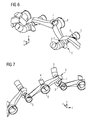
- Fig. 5 now shows an oblique view of the mixture outlet pipes 3, the cooling air outlets 4, the fuel inlet pipes 5 and the air inlet pipes 6 of the pilot burner 1 of Fig. 1 shown separately from its annular base body 2 from the front side. That means that Fig. 5 is just a "virtual" view through the material of the annular base body 2, meaning that the hollow pipes are shown as concrete objects. The annular base body 2 is not shown directly. As it can be seen the mixture outlet pipes 3, the cooling air outlets 4, the fuel inlet pipes 5 and the air inlet pipes 6 of the pilot burner 1 are substantially passages through the annular base body 2.
- Fig. 6 shows a detail view of the arrangement shown in Fig. 5 from the front side
- Fig. 7 shows a detail view of the arrangement shown in Fig. 5 from the back side.
- Figs. 5 to 7 disclose a connection section 7 connecting a fuel inlet pipe 5, an air inlet pipe 6 and a mixture outlet pipe 3. Furthermore, helical fins 8 of the fuel inlet pipe 5 and a helically shaped part 9 of the air inlet pipe 6 is shown.
- Figs. 1 to 7 disclose a pilot burner 1 for a gas turbine, comprising an annular base body 2 with a fuel inlet pipe 5, an air inlet pipe 6 and a mixture outlet pipe 3 connected at a connection section 7.
- the fuel inlet pipe 5 and the air inlet pipe 6 comprise separate means 8, 9 for axially swirling of the transported media.
- said swirling means of the fuel inlet pipe 5 are embodied as helical fins 8.
- helical grooves may be applicable instead or in addition as well.
- a straight pipe may be used for swirling.
- more or less any other shape of the pipe is applicable as well, as swirling is done by the helical grooves and/or fins 8.
- the means 8 i.e. the helical grooves and/or fins 8) provide individually a swirl to the fuel.
- the swirling means of the air inlet pipe 6 are embodied as a helically shaped part 9 of said air inlet pipe 6. In this way, a pipe with a smooth inner surface may be used as swirling is done by the course of the pipe.
- the means 9 i.e. the helically shaped part 9 provide individually a swirl to the air.
- swirling means of the air inlet pipe 6 are embodied as helical grooves and/or fins 8 and the swirling means of the fuel inlet pipe 5 are embodied as a helically shaped part 9 of the same.
- rotational directions of the swirling means 8, 9 of said fuel inlet pipe 5 and said air inlet pipe 6 are unidirectional. In this way, a quite long interphase transfer area improves the mixing of the fluids, i.e. air and fuel.
- the rotational directions of the swirling means 8, 9 of said fuel inlet pipe 5 and said air inlet pipe 6 may also be counter-directional. In this way, quite intense turbulences improve the mixing of the fluids, i.e. air and fuel.
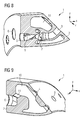
- Fig. 8 now shows a cross section of the pilot burner 1 of the Figs. 1 to 7 in the connection section 7 respectively mixing section. Furthermore, a cooling chamber 10 respectively cooling grid is shown in the annular base body 2. That means that the connection section 7 (or mixing section) and the cooling chamber 10 (or cooling grid) may also each be passages within the annular base body 2.
- Fig. 9 furthermore shows a cross section of the pilot burner 1 of Fig. 1 in a cooling air tapping section 11, by which a part of the air entering the air inlet pipe 6 is guided through the cooling chamber 10 and finally through cooling air outlets 4. In this way, the pilot burner 1 can be cooled.
- the cooling chamber 10 may cool the material of the annular base body 2, particularly cooling internal surfaces of the annular base body 2. Furthermore cooling air can also exit via cooling air outlets 4 allowing to cool an external front surface of the annular base body 2.
- Fig. 10 finally shows a schematic view of an exemplary gas turbine 12.
- the gas turbine 12 (also called gas turbine engine) comprises a compressor 13, a combustion chamber 14 and a turbine 15 as it is known per se.
- the pilot burner 1 of the kind presented above may be used, being arranged in the region of the combustion chamber 14.
- the pilot burner 1 is particularly present to provide pilot fuel for start-up or transient mode of operations to stabilize the flame and/or combustion.
- the pilot fuel may be gaseous fuel. In another embodiment pilot fuel may be liquid fuel.
- the shape of the channels can keep the fluid at a speed over the flame speed at all times. In this way, no combustion can take place inside the burner which prevents flashback.
- a mix of fuel and an oxidizer has a possibility to react and cause a flashback.
- a higher velocity of the jet out of the pilot tip may keep the pilot flame further away from the tip and therefore also make the metal less hot.
- the complex structures within the annular base body 2 as disclosed in this text may be produced by 3D printing or additive manufacturing, e.g. via selective laser sintering, selective laser melting and similar methods.
Landscapes
- Engineering & Computer Science (AREA)
- Chemical & Material Sciences (AREA)
- Combustion & Propulsion (AREA)
- Mechanical Engineering (AREA)
- General Engineering & Computer Science (AREA)
- Gas Burners (AREA)
Abstract
It is described a pilot burner (1) for a gas turbine (12), comprising an annular base body (2) with a fuel inlet pipe (5), an air inlet pipe (6) and a mixture outlet pipe (3) connected at a connection section (7). Said fuel inlet pipe (5) and said air inlet pipe (6) comprise separate means (8, 9) for axially swirling of the transported media, e.g. embodied as helical grooves and/or fins (8) in the inlet pipes (5, 6) or embodied as a helically shaped part (9) of said inlet pipes (5, 6). Furthermore, a gas turbine (12) comprising a compressor (13), a combustion chamber (14), a turbine (15) and a pilot burner (1) of the kind above is disclosed.
Description
- The present invention relates to a pilot burner for a gas turbine, comprising an annular base body with a fuel inlet pipe, an air inlet pipe and a mixture outlet pipe connected at a connection section. Furthermore, the present invention relates to a gas turbine comprising a compressor, a turbine, a combustion chamber and a pilot burner of the kind above.
- A pilot burner and a gas turbine as presented above are generally known. Air and fuel are mixed to form a flammable mixture, which is ignited and forms a pilot flame for a burner in the combustion chamber. It is not just about generating a flame, but also strict environmental rules have to be taken care of. For this reason, air and fuel shall be mixed well what sometimes is done by radial swirlers or not at all. However, known solutions suffer of rather poor pre-mixing of fuel and air, comparably high material temperatures in the burner body going hand in hand with a short life time and risk of flashback, where fuel is injected into the combustion systems.
- Accordingly, there is a need to provide a pilot burner, which overcomes the drawbacks mentioned above.
- This need may be met by the subject matter according to the independent claims. Advantageous embodiments of the present invention are described by the dependent claims.
- According to a first aspect of the invention, there is provided a pilot burner as disclosed in the opening paragraph, wherein said fuel inlet pipe and said air inlet pipe comprise separate means for axially swirling of the transported media.
- Moreover, there is provided a gas turbine comprising a compressor, a turbine, a combustion chamber and a pilot burner of the kind above.
- These aspects of the invention are based on the idea that axially swirling provides for a comparably long mixing distance. In this way the drawbacks mentioned above may be avoided. In particular, fuel and air is mixed very well what leads to comparably low nitrogen oxide emissions (NOx-emissions). Furthermore, temperatures in the burner body are reduced which leads to longer life time of the components. Finally, problems with flashback, where fuel is injected into the combustion systems, are reduced as well.
- According to a further embodiment of the invention, said swirling means are embodied as helical grooves and/or fins. In this way, a straight pipe may be used for swirling. However, more or less any other shape of the pipe is applicable as well, as swirling is done by the helical grooves and/or fins.
- According to yet another embodiment of the invention, said swirling means are embodied as a helically shaped part of said fuel inlet pipe and/or said air inlet pipe. In this way, a pipe with a smooth inner surface may be used as swirling is done by the course of the pipe.
- According to a further embodiment of the invention, rotational directions of the swirling means of said fuel inlet pipe and said air inlet pipe are unidirectional. In this way, a quite long interphase transfer area improves the mixing of the fluids, i.e. air and fuel.
- According to yet another embodiment of the invention, rotational directions of the swirling means of said fuel inlet pipe and said air inlet pipe are counter-directional. In this way, quite intense turbulences improve the mixing of the fluids, i.e. air and fuel.
- In a further embodiment the pilot burner comprises a cooling chamber respectively cooling grid connected to the air inlet pipe and to cooling air outlets in the region of the mixture outlet pipes. In this way, the pilot burner can be cooled. In particular, air is tapped before mixing with fuel, goes through the entire burner tip and later is released into the combustion chamber. The taken measures keep most of the tip at the same temperature as the incoming air by the insulation effect of the air in the grid.
- It has to be noted that embodiments of the invention have been described with reference to different subject matters. However, a person skilled in the art will gather from the above and the following description that, unless other notified, in addition to any combination of features belonging to one type of subject matter also any combination between features relating to different subject matters is considered as to be disclosed with this document.
- The aspects defined above and further aspects of the present invention are apparent from the examples of embodiment to be described hereinafter and are explained with reference to the examples of embodiment. The invention will be described in more detail hereinafter with reference to examples of embodiment but to which the invention is not limited.
-
-
Figure 1 shows a schematic oblique view of an exemplary pilot burner from the front side; -
Figure 2 shows a front view of the pilot burner ofFig. 1 ; -
Figure 3 shows a back view of the pilot burner ofFig. 1 ; -
Figure 4 shows a side view of the pilot burner ofFig. 1 ; -
Figure 5 shows an oblique view of the fuel inlet pipes, the air inlet pipes and the mixture outlet pipes of the pilot burner ofFig. 1 shown separately from its annular base body from the front side; -
Figure 6 shows a detail view of the arrangement shown inFig. 5 ; -
Figure 7 shows a detail view of the arrangement shown inFig. 5 from the back side; -
Figure 8 shows a cross section of the pilot burner ofFig. 1 in the connection section respectively mixing section; -
Figure 9 shows a cross section of the pilot burner ofFig. 1 in cooling air tapping section and -
Figure 10 shows a schematic view of an exemplary gas turbine, in which the pilot burner may be used. - The illustration in the drawing is schematically. It is noted that in different figures, similar or identical elements or features are provided with the same reference signs or with reference signs, which are different from the corresponding reference signs only within the first digit. In order to avoid unnecessary repetitions elements or features which have already been elucidated with respect to a previously described embodiment are not elucidated again at a later position of the description.
-
Fig. 1 shows a schematic oblique view of an exemplary pilot burner 1 from the front side. In particular,Fig. 1 shows anannular base body 2 of the pilot burner 1 withmixture outlet pipes 3 andcooling air outlets 4. It can be seen that preferably themixture outlet pipes 3 for fuel and thecooling air outlets 4 may be arranged such that they end at a conical section of theannular base body 2. Particularly outlet holes of themixture outlet pipes 3 may be distributed over the circumference of the conical section. Particularly outlet holes of thecooling air outlets 4 may be distributed over the circumference of the conical section. Furthermore themixture outlet pipes 3 and thecooling air outlets 4 may be arranged alternately. -
Fig. 2 furthermore shows a front view of the pilot burner ofFig. 1 also showing themixture outlet pipes 3 andcooling air outlets 4. -
Fig. 3 shows a back view of the pilot burner ofFig. 1 , in particularfuel inlet pipes 5 andair inlet pipes 6. Thefuel inlet pipes 5 and theair inlet pipes 6 may be arranged alternately over the circumference. - Furthermore,
Fig. 4 shows a side view of the pilot burner ofFig. 1 . In particular, themixture outlet pipes 3 and coolingair outlets 4 are shown again. -
Fig. 5 now shows an oblique view of themixture outlet pipes 3, thecooling air outlets 4, thefuel inlet pipes 5 and theair inlet pipes 6 of the pilot burner 1 ofFig. 1 shown separately from itsannular base body 2 from the front side. That means thatFig. 5 is just a "virtual" view through the material of theannular base body 2, meaning that the hollow pipes are shown as concrete objects. Theannular base body 2 is not shown directly. As it can be seen themixture outlet pipes 3, the coolingair outlets 4, thefuel inlet pipes 5 and theair inlet pipes 6 of the pilot burner 1 are substantially passages through theannular base body 2. -
Fig. 6 shows a detail view of the arrangement shown inFig. 5 from the front side andFig. 7 shows a detail view of the arrangement shown inFig. 5 from the back side. - In particular,
Figs. 5 to 7 disclose aconnection section 7 connecting afuel inlet pipe 5, anair inlet pipe 6 and amixture outlet pipe 3. Furthermore,helical fins 8 of thefuel inlet pipe 5 and a helically shaped part 9 of theair inlet pipe 6 is shown. - Accordingly,
Figs. 1 to 7 disclose a pilot burner 1 for a gas turbine, comprising anannular base body 2 with afuel inlet pipe 5, anair inlet pipe 6 and amixture outlet pipe 3 connected at aconnection section 7. Thefuel inlet pipe 5 and theair inlet pipe 6 compriseseparate means 8, 9 for axially swirling of the transported media. - Concretely, said swirling means of the
fuel inlet pipe 5 are embodied ashelical fins 8. However, helical grooves may be applicable instead or in addition as well. In this way, a straight pipe may be used for swirling. However, more or less any other shape of the pipe is applicable as well, as swirling is done by the helical grooves and/orfins 8. - Thus the means 8 (i.e. the helical grooves and/or fins 8) provide individually a swirl to the fuel.
- Moreover, the swirling means of the
air inlet pipe 6 are embodied as a helically shaped part 9 of saidair inlet pipe 6. In this way, a pipe with a smooth inner surface may be used as swirling is done by the course of the pipe. - Thus the means 9 (i.e. the helically shaped part 9) provide individually a swirl to the air.
- One skilled in the art will easily perceive an embodiment, in which the swirling means of the
air inlet pipe 6 are embodied as helical grooves and/orfins 8 and the swirling means of thefuel inlet pipe 5 are embodied as a helically shaped part 9 of the same. - Recent research activities have shown that axially swirling provides for a comparably long mixing distance. In this way the following advantages may be obtained:
- fuel and air are mixed very well what leads to comparably low NOx-emissions,
- temperatures in the
burner body 2 are reduced which leads to longer life time of the components, - problems with flashback where fuel is injected into the combustion systems are reduced.
- In the example shown in
Figs 1 to 7 rotational directions of the swirling means 8, 9 of saidfuel inlet pipe 5 and saidair inlet pipe 6 are unidirectional. In this way, a quite long interphase transfer area improves the mixing of the fluids, i.e. air and fuel. - However, the rotational directions of the swirling means 8, 9 of said
fuel inlet pipe 5 and saidair inlet pipe 6 may also be counter-directional. In this way, quite intense turbulences improve the mixing of the fluids, i.e. air and fuel. -
Fig. 8 now shows a cross section of the pilot burner 1 of theFigs. 1 to 7 in theconnection section 7 respectively mixing section. Furthermore, a coolingchamber 10 respectively cooling grid is shown in theannular base body 2. That means that the connection section 7 (or mixing section) and the cooling chamber 10 (or cooling grid) may also each be passages within theannular base body 2. -
Fig. 9 furthermore shows a cross section of the pilot burner 1 ofFig. 1 in a coolingair tapping section 11, by which a part of the air entering theair inlet pipe 6 is guided through the coolingchamber 10 and finally through coolingair outlets 4. In this way, the pilot burner 1 can be cooled. - The taken measures keep most of the burner 1 at the same temperature by the insulation effect of the air in the cooling
chamber 10. Thus, the coolingchamber 10 may cool the material of theannular base body 2, particularly cooling internal surfaces of theannular base body 2. Furthermore cooling air can also exit via coolingair outlets 4 allowing to cool an external front surface of theannular base body 2. -
Fig. 10 finally shows a schematic view of anexemplary gas turbine 12. The gas turbine 12 (also called gas turbine engine) comprises acompressor 13, acombustion chamber 14 and aturbine 15 as it is known per se. In thisgas turbine 12 the pilot burner 1 of the kind presented above may be used, being arranged in the region of thecombustion chamber 14. - The pilot burner 1 is particularly present to provide pilot fuel for start-up or transient mode of operations to stabilize the flame and/or combustion. The pilot fuel may be gaseous fuel. In another embodiment pilot fuel may be liquid fuel.
- Generally, the shape of the channels can keep the fluid at a speed over the flame speed at all times. In this way, no combustion can take place inside the burner which prevents flashback. Advantageously, there are no stagnation areas of the flow, where a mix of fuel and an oxidizer has a possibility to react and cause a flashback. Moreover, a higher velocity of the jet out of the pilot tip may keep the pilot flame further away from the tip and therefore also make the metal less hot.
- The complex structures within the
annular base body 2 as disclosed in this text may be produced by 3D printing or additive manufacturing, e.g. via selective laser sintering, selective laser melting and similar methods. - Finally, it should be noted that the term "comprising" does not exclude other elements or steps and the use of articles "a" or "an" does not exclude a plurality. Also elements described in association with different embodiments may be combined. It should also be noted that reference signs in the claims should not be construed as limiting the scope of the claims.
Claims (7)
- Pilot burner (1) for a gas turbine (12), comprising an annular base body (2) with a fuel inlet pipe (5), an air inlet pipe (6) and a mixture outlet pipe (3) connected at a connection section (7),
wherein
said fuel inlet pipe (5) and said air inlet pipe (6) comprise separate means (8, 9) for axially swirling of the transported media. - Pilot burner (1) as claimed in claim 1, wherein said swirling means are embodied as helical grooves and/or fins (8).
- Pilot burner (1) as claimed in claim 1 or 2, wherein said swirling means are embodied as a helically shaped part (9) of said fuel inlet pipe (5) and/or said air inlet pipe (6).
- Pilot burner (1) as claimed in any one of the claims 1 to 3, wherein rotational directions of the swirling means (8, 9) of said fuel inlet pipe (5) and said air inlet pipe (6) are unidirectional.
- Pilot burner (1) as claimed in any one of the claims 1 to 3, wherein rotational directions of the swirling means (8, 9) of said fuel inlet pipe (5) and said air inlet pipe (6) are counter-directional.
- Pilot burner (1) as claimed in any one of the claims 1 to 5, comprising a cooling chamber (10) respectively cooling grid connected to the air inlet pipe (6) and to cooling air outlets (4) in the region of the mixture outlet pipes (3).
- Gas turbine (12) comprising a compressor (13), a combustion chamber (14), a turbine (15) and a pilot burner (1) as claimed in claims 1 to 6.
Priority Applications (2)
| Application Number | Priority Date | Filing Date | Title |
|---|---|---|---|
| EP14154321.5A EP2905539A1 (en) | 2014-02-07 | 2014-02-07 | Pilot burner with axial swirlers for a gas turbine |
| PCT/EP2015/050462 WO2015117794A1 (en) | 2014-02-07 | 2015-01-13 | Pilot burner with axial swirlers for a gas turbine |
Applications Claiming Priority (1)
| Application Number | Priority Date | Filing Date | Title |
|---|---|---|---|
| EP14154321.5A EP2905539A1 (en) | 2014-02-07 | 2014-02-07 | Pilot burner with axial swirlers for a gas turbine |
Publications (1)
| Publication Number | Publication Date |
|---|---|
| EP2905539A1 true EP2905539A1 (en) | 2015-08-12 |
Family
ID=50068899
Family Applications (1)
| Application Number | Title | Priority Date | Filing Date |
|---|---|---|---|
| EP14154321.5A Withdrawn EP2905539A1 (en) | 2014-02-07 | 2014-02-07 | Pilot burner with axial swirlers for a gas turbine |
Country Status (2)
| Country | Link |
|---|---|
| EP (1) | EP2905539A1 (en) |
| WO (1) | WO2015117794A1 (en) |
Cited By (3)
| Publication number | Priority date | Publication date | Assignee | Title |
|---|---|---|---|---|
| EP3301367A1 (en) * | 2016-09-30 | 2018-04-04 | Siemens Aktiengesellschaft | Machine component, particularly a turbomachine component, with cooling features and a method for manufacturing and of operation |
| WO2018118466A1 (en) * | 2016-12-22 | 2018-06-28 | Siemens Aktiengesellschaft | Fuel manifold in a combustor for a gas turbine engine |
| CN113494361A (en) * | 2020-04-08 | 2021-10-12 | 通用电气公司 | Combustor cooling structure |
Citations (7)
| Publication number | Priority date | Publication date | Assignee | Title |
|---|---|---|---|---|
| FR2641365A1 (en) * | 1988-12-30 | 1990-07-06 | Pillard Chauffage | METHODS AND DEVICES FOR FINALLY SPRAYING LIQUID FUEL AND BURNERS EQUIPPED WITH SUCH DEVICES |
| US20040067461A1 (en) * | 2000-11-27 | 2004-04-08 | Harald Ranke | Burner and method for the chemical reaction of two gas streams |
| US20090158743A1 (en) * | 2007-12-19 | 2009-06-25 | Rolls-Royce Plc | Fuel distribution apparatus |
| EP2110601A1 (en) * | 2008-04-15 | 2009-10-21 | Siemens Aktiengesellschaft | Burner |
| US20100162713A1 (en) * | 2008-12-31 | 2010-07-01 | Shui-Chi Li | Cooled flameholder swirl cup |
| US20100330521A1 (en) * | 2008-01-29 | 2010-12-30 | Tobias Krieger | Fuel Nozzle Having a Swirl Duct and Method for Producing a Fuel Nozzle |
| DE102011116317A1 (en) * | 2011-10-18 | 2013-04-18 | Rolls-Royce Deutschland Ltd & Co Kg | Magervormian burner of an aircraft gas turbine engine |
-
2014
- 2014-02-07 EP EP14154321.5A patent/EP2905539A1/en not_active Withdrawn
-
2015
- 2015-01-13 WO PCT/EP2015/050462 patent/WO2015117794A1/en not_active Ceased
Patent Citations (7)
| Publication number | Priority date | Publication date | Assignee | Title |
|---|---|---|---|---|
| FR2641365A1 (en) * | 1988-12-30 | 1990-07-06 | Pillard Chauffage | METHODS AND DEVICES FOR FINALLY SPRAYING LIQUID FUEL AND BURNERS EQUIPPED WITH SUCH DEVICES |
| US20040067461A1 (en) * | 2000-11-27 | 2004-04-08 | Harald Ranke | Burner and method for the chemical reaction of two gas streams |
| US20090158743A1 (en) * | 2007-12-19 | 2009-06-25 | Rolls-Royce Plc | Fuel distribution apparatus |
| US20100330521A1 (en) * | 2008-01-29 | 2010-12-30 | Tobias Krieger | Fuel Nozzle Having a Swirl Duct and Method for Producing a Fuel Nozzle |
| EP2110601A1 (en) * | 2008-04-15 | 2009-10-21 | Siemens Aktiengesellschaft | Burner |
| US20100162713A1 (en) * | 2008-12-31 | 2010-07-01 | Shui-Chi Li | Cooled flameholder swirl cup |
| DE102011116317A1 (en) * | 2011-10-18 | 2013-04-18 | Rolls-Royce Deutschland Ltd & Co Kg | Magervormian burner of an aircraft gas turbine engine |
Cited By (8)
| Publication number | Priority date | Publication date | Assignee | Title |
|---|---|---|---|---|
| EP3301367A1 (en) * | 2016-09-30 | 2018-04-04 | Siemens Aktiengesellschaft | Machine component, particularly a turbomachine component, with cooling features and a method for manufacturing and of operation |
| WO2018060200A1 (en) * | 2016-09-30 | 2018-04-05 | Siemens Aktiengesellschaft | Machine component, particularly a turbomachine component, with cooling features and a method for manufacturing and of operation |
| US11371438B2 (en) | 2016-09-30 | 2022-06-28 | Siemens Energy Global GmbH & Co. KG | Machine component, particularly a turbomachine component, with cooling features and a method for manufacturing and of operation |
| WO2018118466A1 (en) * | 2016-12-22 | 2018-06-28 | Siemens Aktiengesellschaft | Fuel manifold in a combustor for a gas turbine engine |
| CN113494361A (en) * | 2020-04-08 | 2021-10-12 | 通用电气公司 | Combustor cooling structure |
| EP3892921A1 (en) * | 2020-04-08 | 2021-10-13 | General Electric Company | Burner cooling structures |
| JP2021167712A (en) * | 2020-04-08 | 2021-10-21 | ゼネラル・エレクトリック・カンパニイ | Burner cooling structure |
| US11774093B2 (en) | 2020-04-08 | 2023-10-03 | General Electric Company | Burner cooling structures |
Also Published As
| Publication number | Publication date |
|---|---|
| WO2015117794A1 (en) | 2015-08-13 |
Similar Documents
| Publication | Publication Date | Title |
|---|---|---|
| CN103032892B (en) | Burner and the method for supplying fuel to burner | |
| CN206973615U (en) | Guide's pre-mixing nozzle and fuel nozzle assembly | |
| EP2629017B1 (en) | Combustor | |
| CN103017199B (en) | Burner and the method being used for supplying fuel to burner | |
| CN103196158B (en) | Burner and the method being used for distributing fuel in the burner | |
| CN103185354B (en) | Methods and systems for cooling a transition nozzle | |
| JP6118024B2 (en) | Combustor nozzle and method of manufacturing combustor nozzle | |
| CN103292353B (en) | For reducing the system and method for the combustion dynamics in burner | |
| US20120055167A1 (en) | Apparatus and method for mixing fuel in a gas turbine nozzle | |
| CN206973617U (en) | Guide's pre-mixing nozzle and fuel nozzle assembly | |
| US20180051883A1 (en) | Pre-mixing based fuel nozzle for use in a combustion turbine engine | |
| JP2015511698A (en) | Mixing device for mixing fuel into a flow of oxygen-containing gas | |
| EP2578940A2 (en) | Combustor and method for supplying flow to a combustor | |
| EP2905539A1 (en) | Pilot burner with axial swirlers for a gas turbine | |
| EP2592349A2 (en) | Combustor and method for supplying fuel to a combustor | |
| EP2554911A2 (en) | Fuel Nozzle | |
| CN103375817A (en) | fuel nozzle | |
| JP6417620B2 (en) | Combustor, gas turbine | |
| CN102628593B (en) | Device for fuel combination in the gas turbine | |
| EP2657607A2 (en) | Combustor apparatus for stoichiometric combustion | |
| CN103196153B (en) | The burner of turbine | |
| CN103925617B (en) | The stream set of turbomachinery component | |
| EP2629015A2 (en) | Outer fuel nozzle inlet flow conditioner interface to end cap |
Legal Events
| Date | Code | Title | Description |
|---|---|---|---|
| PUAI | Public reference made under article 153(3) epc to a published international application that has entered the european phase |
Free format text: ORIGINAL CODE: 0009012 |
|
| AK | Designated contracting states |
Kind code of ref document: A1 Designated state(s): AL AT BE BG CH CY CZ DE DK EE ES FI FR GB GR HR HU IE IS IT LI LT LU LV MC MK MT NL NO PL PT RO RS SE SI SK SM TR |
|
| AX | Request for extension of the european patent |
Extension state: BA ME |
|
| STAA | Information on the status of an ep patent application or granted ep patent |
Free format text: STATUS: THE APPLICATION IS DEEMED TO BE WITHDRAWN |
|
| 18D | Application deemed to be withdrawn |
Effective date: 20160213 |