EP2905457A1 - Valve assembly and fluid injector for a combustion engine - Google Patents
Valve assembly and fluid injector for a combustion engine Download PDFInfo
- Publication number
- EP2905457A1 EP2905457A1 EP14151237.6A EP14151237A EP2905457A1 EP 2905457 A1 EP2905457 A1 EP 2905457A1 EP 14151237 A EP14151237 A EP 14151237A EP 2905457 A1 EP2905457 A1 EP 2905457A1
- Authority
- EP
- European Patent Office
- Prior art keywords
- valve
- sac volume
- valve body
- area
- conically shaped
- Prior art date
- Legal status (The legal status is an assumption and is not a legal conclusion. Google has not performed a legal analysis and makes no representation as to the accuracy of the status listed.)
- Granted
Links
Images

Classifications
-
- F—MECHANICAL ENGINEERING; LIGHTING; HEATING; WEAPONS; BLASTING
- F02—COMBUSTION ENGINES; HOT-GAS OR COMBUSTION-PRODUCT ENGINE PLANTS
- F02M—SUPPLYING COMBUSTION ENGINES IN GENERAL WITH COMBUSTIBLE MIXTURES OR CONSTITUENTS THEREOF
- F02M61/00—Fuel-injectors not provided for in groups F02M39/00 - F02M57/00 or F02M67/00
- F02M61/04—Fuel-injectors not provided for in groups F02M39/00 - F02M57/00 or F02M67/00 having valves, e.g. having a plurality of valves in series
-
- F—MECHANICAL ENGINEERING; LIGHTING; HEATING; WEAPONS; BLASTING
- F02—COMBUSTION ENGINES; HOT-GAS OR COMBUSTION-PRODUCT ENGINE PLANTS
- F02M—SUPPLYING COMBUSTION ENGINES IN GENERAL WITH COMBUSTIBLE MIXTURES OR CONSTITUENTS THEREOF
- F02M61/00—Fuel-injectors not provided for in groups F02M39/00 - F02M57/00 or F02M67/00
- F02M61/04—Fuel-injectors not provided for in groups F02M39/00 - F02M57/00 or F02M67/00 having valves, e.g. having a plurality of valves in series
- F02M61/10—Other injectors with elongated valve bodies, i.e. of needle-valve type
-
- F—MECHANICAL ENGINEERING; LIGHTING; HEATING; WEAPONS; BLASTING
- F02—COMBUSTION ENGINES; HOT-GAS OR COMBUSTION-PRODUCT ENGINE PLANTS
- F02M—SUPPLYING COMBUSTION ENGINES IN GENERAL WITH COMBUSTIBLE MIXTURES OR CONSTITUENTS THEREOF
- F02M61/00—Fuel-injectors not provided for in groups F02M39/00 - F02M57/00 or F02M67/00
- F02M61/04—Fuel-injectors not provided for in groups F02M39/00 - F02M57/00 or F02M67/00 having valves, e.g. having a plurality of valves in series
- F02M61/042—The valves being provided with fuel passages
- F02M61/045—The valves being provided with fuel discharge orifices
-
- F—MECHANICAL ENGINEERING; LIGHTING; HEATING; WEAPONS; BLASTING
- F02—COMBUSTION ENGINES; HOT-GAS OR COMBUSTION-PRODUCT ENGINE PLANTS
- F02M—SUPPLYING COMBUSTION ENGINES IN GENERAL WITH COMBUSTIBLE MIXTURES OR CONSTITUENTS THEREOF
- F02M61/00—Fuel-injectors not provided for in groups F02M39/00 - F02M57/00 or F02M67/00
- F02M61/16—Details not provided for in, or of interest apart from, the apparatus of groups F02M61/02 - F02M61/14
- F02M61/18—Injection nozzles, e.g. having valve seats; Details of valve member seated ends, not otherwise provided for
-
- F—MECHANICAL ENGINEERING; LIGHTING; HEATING; WEAPONS; BLASTING
- F02—COMBUSTION ENGINES; HOT-GAS OR COMBUSTION-PRODUCT ENGINE PLANTS
- F02M—SUPPLYING COMBUSTION ENGINES IN GENERAL WITH COMBUSTIBLE MIXTURES OR CONSTITUENTS THEREOF
- F02M61/00—Fuel-injectors not provided for in groups F02M39/00 - F02M57/00 or F02M67/00
- F02M61/16—Details not provided for in, or of interest apart from, the apparatus of groups F02M61/02 - F02M61/14
- F02M61/18—Injection nozzles, e.g. having valve seats; Details of valve member seated ends, not otherwise provided for
- F02M61/1886—Details of valve seats not covered by groups F02M61/1866 - F02M61/188
-
- F—MECHANICAL ENGINEERING; LIGHTING; HEATING; WEAPONS; BLASTING
- F02—COMBUSTION ENGINES; HOT-GAS OR COMBUSTION-PRODUCT ENGINE PLANTS
- F02M—SUPPLYING COMBUSTION ENGINES IN GENERAL WITH COMBUSTIBLE MIXTURES OR CONSTITUENTS THEREOF
- F02M61/00—Fuel-injectors not provided for in groups F02M39/00 - F02M57/00 or F02M67/00
- F02M61/16—Details not provided for in, or of interest apart from, the apparatus of groups F02M61/02 - F02M61/14
- F02M61/20—Closing valves mechanically, e.g. arrangements of springs or weights or permanent magnets; Damping of valve lift
-
- F—MECHANICAL ENGINEERING; LIGHTING; HEATING; WEAPONS; BLASTING
- F02—COMBUSTION ENGINES; HOT-GAS OR COMBUSTION-PRODUCT ENGINE PLANTS
- F02M—SUPPLYING COMBUSTION ENGINES IN GENERAL WITH COMBUSTIBLE MIXTURES OR CONSTITUENTS THEREOF
- F02M2200/00—Details of fuel-injection apparatus, not otherwise provided for
- F02M2200/06—Fuel-injection apparatus having means for preventing coking, e.g. of fuel injector discharge orifices or valve needles
-
- F—MECHANICAL ENGINEERING; LIGHTING; HEATING; WEAPONS; BLASTING
- F02—COMBUSTION ENGINES; HOT-GAS OR COMBUSTION-PRODUCT ENGINE PLANTS
- F02M—SUPPLYING COMBUSTION ENGINES IN GENERAL WITH COMBUSTIBLE MIXTURES OR CONSTITUENTS THEREOF
- F02M51/00—Fuel-injection apparatus characterised by being operated electrically
- F02M51/06—Injectors peculiar thereto with means directly operating the valve needle
- F02M51/061—Injectors peculiar thereto with means directly operating the valve needle using electromagnetic operating means
- F02M51/0625—Injectors peculiar thereto with means directly operating the valve needle using electromagnetic operating means characterised by arrangement of mobile armatures
- F02M51/0664—Injectors peculiar thereto with means directly operating the valve needle using electromagnetic operating means characterised by arrangement of mobile armatures having a cylindrically or partly cylindrically shaped armature, e.g. entering the winding; having a plate-shaped or undulated armature entering the winding
-
- F—MECHANICAL ENGINEERING; LIGHTING; HEATING; WEAPONS; BLASTING
- F02—COMBUSTION ENGINES; HOT-GAS OR COMBUSTION-PRODUCT ENGINE PLANTS
- F02M—SUPPLYING COMBUSTION ENGINES IN GENERAL WITH COMBUSTIBLE MIXTURES OR CONSTITUENTS THEREOF
- F02M61/00—Fuel-injectors not provided for in groups F02M39/00 - F02M57/00 or F02M67/00
- F02M61/16—Details not provided for in, or of interest apart from, the apparatus of groups F02M61/02 - F02M61/14
- F02M61/18—Injection nozzles, e.g. having valve seats; Details of valve member seated ends, not otherwise provided for
- F02M61/1866—Valve seats or member ends having multiple cones
-
- F—MECHANICAL ENGINEERING; LIGHTING; HEATING; WEAPONS; BLASTING
- F02—COMBUSTION ENGINES; HOT-GAS OR COMBUSTION-PRODUCT ENGINE PLANTS
- F02M—SUPPLYING COMBUSTION ENGINES IN GENERAL WITH COMBUSTIBLE MIXTURES OR CONSTITUENTS THEREOF
- F02M61/00—Fuel-injectors not provided for in groups F02M39/00 - F02M57/00 or F02M67/00
- F02M61/16—Details not provided for in, or of interest apart from, the apparatus of groups F02M61/02 - F02M61/14
- F02M61/18—Injection nozzles, e.g. having valve seats; Details of valve member seated ends, not otherwise provided for
- F02M61/188—Spherical or partly spherical shaped valve member ends
-
- Y—GENERAL TAGGING OF NEW TECHNOLOGICAL DEVELOPMENTS; GENERAL TAGGING OF CROSS-SECTIONAL TECHNOLOGIES SPANNING OVER SEVERAL SECTIONS OF THE IPC; TECHNICAL SUBJECTS COVERED BY FORMER USPC CROSS-REFERENCE ART COLLECTIONS [XRACs] AND DIGESTS
- Y02—TECHNOLOGIES OR APPLICATIONS FOR MITIGATION OR ADAPTATION AGAINST CLIMATE CHANGE
- Y02T—CLIMATE CHANGE MITIGATION TECHNOLOGIES RELATED TO TRANSPORTATION
- Y02T10/00—Road transport of goods or passengers
- Y02T10/10—Internal combustion engine [ICE] based vehicles
- Y02T10/30—Use of alternative fuels, e.g. biofuels
Definitions
- the invention relates to a valve assembly for a fluid injector for an internal combustion engine, wherein the valve assembly comprises a valve body with a valve recess and central longitudinal axis.
- Injectors are in widespread use, in particular for internal combustion engines, where they may be arranged in order to dose a fluid into an intake manifold of the internal combustion engine or directly into a combustion chamber of a cylinder of the internal combustion engine.
- One possible starting point is to reduce the pollutant emissions which are directly produced by the combustion engine. For example after an injection process, when a valve needle has returned to its closing position, a remaining fuel volume inside an injector in the region of a nozzle tip can cause deposition of not combusted particles. This leads to high carbon- (also HC-) and particle number (also PN-) emissions, and thus is a challenge in order to fulfill legal regulations such as the European Emission Normative EU6C.
- One object of the invention is to specify an injector for a combustion engine which facilitates a reliable and precise function and makes a contribution to particularly small pollutant emissions.
- a valve assembly for a fluid injector for an internal combustion engine is specified. Further, a fluid injector for a combustion engine is specified, the fluid injector comprising the valve assembly and in particular an actuator.
- the fluid injector is in particular a fuel injector. It may preferably be provided for injecting fuel directly into a combustion chamber of the internal combustion engine.
- the injector comprises a valve body with a valve recess, a central longitudinal axis and a first axial end and a second axial end with respect to the central longitudinal axis. Furthermore, the injector comprises a valve needle being axially movable within the valve recess with respect to the central longitudinal axis.
- the valve needle prevents, in concurrence with a seal seat area of the valve body, a fluid flow through at least one flow hole in its closing position and otherwise enables it.
- the valve needle is in mechanical contact with the seal seat area when the valve needle is in the closing position.
- the valve body also comprises a sac volume step adjacent to the seal seat area and in particular downstream of the seal seat area.
- the sac volume step forms a part of an inner surface of a wall of the valve body.
- the sac volume step is defined by a section of an inner circumferential surface of the valve body.
- the injector comprises a sac volume being designed as one end of the valve recess and being limited by a further part of the inner surface of the wall of the valve body.
- the further part of the inner surface extends away from the sac volume step towards the first axial end of the valve body.
- the injector comprises at least one flow hole which penetrates the wall of the valve body in the region of the sac volume from the valve recess to an outside region of the valve body.
- This design of an injector for a combustion engine comprising a sac volume step in combination with the location of the respective flow hole enables advantageous flow field dynamics in the region of the sac volume.
- a sac volume step leads to turbulences of the flowing fluid so that the flow is not laminar anymore. For this reason some kinetic energy of the flowing fluid can be transferred to the remaining fuel in the sac volume and the effect of this is a contribution to an emptying of the sac volume.
- Yet another advantage of the reduction of remaining fuel in the region of the sac volume after the valve needle has returned to its closing position is obviating a nozzle tip wetting and hence reducing PN-emission.
- the injector comprises a sac volume step which substantially extends parallel to the central longitudinal axis.
- This orientation of the sac volume step allows for unique flow field dynamics and flow conditions for emptying the sac volume after the valve needle has returned to its closing position and makes a contribution to keep remaining fuel little inside the sac volume.
- a step height of the sac volume step is represented by an axial length of the sac volume step.
- the sac volume step may, for example, have a step height in the range between 0.01 mm and 0.15 mm, the limits being included.
- the inlet of the flow hole is arranged proximate to the sac volume step and, in particular, closer to the sac volume step than to the central longitudinal axis.
- a distance between the inlet of the flow hole and the sac volume step may for example be less than 0.1 mm.
- Such an arrangement of the flow hole is advantageous for the flow field dynamics and can further improve emptying the sac volume from the remaining fuel after the valve needle has returned to its closing position.
- the further part of the inner surface of the wall of the valve body which limits the sac volume comprises a conically shaped area adjacent to the sac volume step.
- the conically shaped area has a decreasing distance to the central longitudinal axis in the direction towards the first axial end of the valve body.
- a cone angle of the conically shaped area between 130° and 150°, the limits being included, is preferable for flow conditions of the flowing fluid.
- a first diameter of a free volume of the valve recess in the region of the sac volume step is represented by a geometrical distance of opposite sides of the sac volume step in reference to a cross section with respect to the central longitudinal axis.
- the first diameter may be in a range between 1.0 mm and 1.4 mm, the limits being included.
- the further part of the inner surface of the wall of the valve body limiting the sac volume comprises a flat shaped ground area adjacent to the conically shaped area.
- the flat shape of the ground area is substantially perpendicular with respect to the central longitudinal axis.
- the size of the flat shaped ground area is distinguished by a second diameter.
- the second diameter may be within the range from 0.4 mm to 0.8 mm, the limits being included.
- the further part of the inner surface of the wall of the valve body limiting the sac volume comprises a spherically shaped ground area adjacent to the conically shaped area.
- the size of the spherically shaped ground area is represented by its radius which also may be denoted as an indentation radius.
- the indentation radius is in between 0.2 mm to 0.4 mm. This allows for efficient energy transfer from the flowing fluid to the remaining fuel inside the sac volume after one injection process. Hence it is advantageous to the flow conditions for emptying the sac volume after the valve needle has returned to its closing position.
- the further part of the inner surface of the wall of the valve body limiting the sac volume comprises a conically shaped ground area adjacent to the conically shaped area.
- the conical shape of the conically shaped ground area has a different angle to the central longitudinal axis than the conically shaped area and has a decreasing distance to the central longitudinal axis in the direction towards the first axial end of the valve body.
- the cone angle of the conically shaped area is in between 130° and 150°, whereas the cone angle of the conically shaped ground area is in between 90° and 120°.
- an advantageous height of the conically shaped ground area is in the range from 0.2 mm to 0.4 mm.
- the height of the conically shaped ground area represents a geometrical length parallel to the central longitudinal axis from a point where the conical shape of the conically shaped area differs from the one of the conically shaped ground area to a point where the valve recess ends in the direction towards the first axial end of the valve body.
- the further part of the inner surface of the wall of the valve body comprises a spherically shaped part of the inner surface adjacent to the conically shaped ground area limiting the sac volume.
- the spherically shaped part is, in other words, positioned subsequent to the conically shaped ground area in axial direction from the second towards the first axial end.
- the inlet of the flow hole of the injector is arranged in the conically shaped area of the sac volume. This positioning of the flow hole is advantageous for the remaining fuel to flow through the flow holes out of the valve body and hence for reliable emptying of the sac volume after an injection process when the valve needle has returned to its closing position.
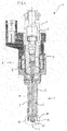
- Figure 1 shows an injector 1 with a nozzle assembly 2 and an actuator 4.
- the actuator 4 functionally interacts with the nozzle assembly 2.
- the nozzle assembly 2 comprises a valve body.
- the valve body comprises a valve body part 3 and a nozzle tip body 15.
- the nozzle tip body 15 is fixedly coupled to the valve body part 3.
- the valve body part 3 and the nozzle tip body 15 can be a single piece.
- the actuator 4 comprises an injector body 6.
- the valve body part 3 is fixedly coupled to the injector body 6, for example by a nozzle clamping nut.
- the valve body part 3 and the injector body 6 form a common housing of the injector 1.
- the valve body has a central longitudinal axis 7. It comprises a wall 9 which defines a valve recess 5. Furthermore the valve body comprises a first axial end and a second axial end, wherein the nozzle tip body 15 is positioned at the first axial end of the valve body.
- a valve needle 11 is arranged axially movable with respect to the central longitudinal axis relative to the valve body.
- the valve needle 11 has a round end portion 12 and is biased by a spring element 17.
- the round end portion 12 may be a ball which is fixed to a shaft of the valve needle 11 at the axial end of the valve needle 11 which faces towards the first axial end of the valve body.
- the actuator 4 has a coil 19 for generating a magnetic field.
- the actuator 4 is operable to actuate the valve needle 11 by means of the magnetic field such that the valve needle 11 can perform a movement along a direction of the central longitudinal axis 7 against the bias of the spring element 17.
- the nozzle tip body 15 limits a free volume of the valve recess 5.
- the nozzle tip body 15 comprises at least one flow hole 13. In other words, the nozzle tip body 15 closes the valve recess 5 at the first axial end, except for the at least one flow hole 13.
- the nozzle tip body 15 further comprises a seal seat area 21, in which the valve needle 11 sealingly rests with its round end portion 12 in its closing position due to forces acting on it, amongst others one force being a spring force by the spring element 17. Details of the nozzle tip body 15 will be explained below with reference to figures 2 to 5 .
- valve needle 11 is movable out of its closing position and into its closing position to enable or prevent a flow of a fluid through the flow hole 13.
- One actuating force is exerted by the spring element 17 in direction of the closing position.
- Another actuating force is exerted by the coil 19 in order to move the valve needle 11 out of its closing position towards an opening position.
- a hydraulic force is a further force acting on the valve needle 11 which may be exerted by the fluid in direction to the closing position of the valve needle 11, in particular due to pressure differences.
- the fluid may be for example gasoline or diesel.
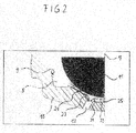
- FIG 2 an enlarged view of the region 20 of figure 1 is shown which exhibits an exemplary constructional design of the nozzle tip body 15 of the injector 1.
- the enlarged view is a longitudinal section view of the nozzle tip body 15.
- the valve needle 11 prevents, in concurrence with the seal seat area 21 a fluid flow through the flow hole 13 in its closing position and otherwise enables it.
- the round end portion 12 of the valve needle 11 abuts the seal seat area 21 when the valve needle 11 is in the closing position to prevent fluid flow through the flow hole 13.
- the actuator 4 is operable to displace the valve needle 11 axially towards the second axial end of the valve body for establishing a gap between the seal seat area 21 and the round end portion 12 for enabling fluid flow from the second axial end through the gap to the flow hole 13 and further through the flow hole 13 out of the valve body.
- fluid flows in the direction from the second axial end towards the first axial end of the valve body in a free volume of the valve recess 5.
- the fluid passes the seal seat area 21 and afterwards a sac volume step 23, which forms a part of an inner surface of the wall 9 of the valve body.
- One fraction of the fluid can directly pass the inlet of the flow hole 13 and exit the valve body to an outside area of the injector 1.
- Another, in particular small, fraction of the fluid enters a sac volume 25, which is designed as one end of the valve recess 5 and which is limited by a further part of the inner surface of the wall 9 of the valve body. Due to the sac volume step 23, flow conditions change and the flow of the fluid is not laminar anymore. Turbulences develop and influence the fluid flow dynamics which is advantageous for a further flow of the fluid.
- Fuel remaining inside the sac volume 25 after the valve needle 11 has returned into contact with the seal seat area 21 may cause pollutant emissions. Because of the introduced turbulent flow generated by the sac volume step 23, some kinetic energy of the flowing fluid can be transferred to the remaining fuel inside the sac volume 25. This kinetic energy of the remaining fuel promotes dispensing a particularly large portion of the remaining fluid - or preferably of the complete remaining fluid - through the flow hole 13 out of the valve body of the injector 1.
- the sac volume step 23 makes a contribution to empty the sac volume 25 after the valve needle 11 has returned to its closing position and therefore reduces the risk for a nozzle tip wetting and for pollutant emissions.
- the sac volume step 23 extends substantially parallel to the central longitudinal axis 7 and that the flow hole 13 is placed close to the sac volume step 23 as shown in figure 2 .
- FIG 3 a furthermore enlarged view of the region 20 of the injector 1 in figure 1 is shown and in particular a detailed view of the inner surface of the sac volume 25.
- the sac volume step 23 adjacent to the seal seat area 21 is substantially extending parallel to the central longitudinal axis 7.
- a conically shaped area 31 adjacent to the sac volume step 23 has a decreasing distance to the central longitudinal axis 7 in the direction of the first axial end of the valve body.
- the conically shaped area 31 has a cone angle alpha.
- the cone angle alpha of the conically shaped area 31 is in between 130° to 150°.
- a first diameter D of a free volume of the valve recess 5 in the region of the sac volume step 23 is represented by a geometrical distance of opposite sides of the sac volume step 23 in reference to a cross section with respect to the central longitudinal axis 7.
- the first diameter D is in between 1.0 mm to 1.4 mm.
- a ground area 33 adjacent to the conically shaped area 31 forms a further part of the inner surface of the wall 9 of the valve body limiting the sac volume 25.
- the ground area 33 has a flat shape defined by a portion of the inner surface of the wall 9 of the valve body.
- the size of the ground area 33 can be characterized by a second diameter d, for example. In this context one advantageous embodiment would comprise a second diameter d in between 0.4 mm to 0.8 mm.
- the sac volume step 23 is distinguished by a step height H, and the step height H of the sac volume step 23 may be within a range from 0.01 mm to 0.15 mm.
- This specific design of the sac volume step 23 adjacent to the seal seat area 21 and the sac volume 25 adjacent to the sac volume step 23 is one advantageous embodiment to generate special fluid flow dynamics and hence enables reliable emptying of the sac volume 25 after an injection process when the valve needle 11 has returned to its closing position and hence obviates a nozzle tip wetting.
- FIG 4 a detailed view of the region 20 of the injector 1 according to another exemplary embodiment for a shape of the sac volume 25 is shown.
- the ground area 33 comprises a further spherically shaped part of the inner surface of the wall 9 of the valve body instead of the flat shape of the previous embodiment.
- the inlets of the flow holes 13 are positioned within the conically shaped area 31 which laterally surrounds the ground area 33.
- the spherical shape of the ground area 33 allows for unique flow field dynamics to enhance emptying of the sac volume 25 and reduce remaining fuel inside the injector 1.
- the spherically shaped ground area 33 can have a radius R. In an advantageous embodiment, the radius R has a value between 0.2 mm and 0.4 mm.
- the ground area 33 of the present sac volume 25 comprises a further conically shaped part of the inner surface of the wall 9 of the valve body forming the ground area 33.
- the further conically shaped part is located adjacent to - and in particular adjoining - the conically shaped area 31.
- the conically shaped ground area 33 has a cone angle beta.
- the cone angle beta of the conically shaped ground area 33 is in between 90° to 120°.
Landscapes
- Engineering & Computer Science (AREA)
- Chemical & Material Sciences (AREA)
- Combustion & Propulsion (AREA)
- Mechanical Engineering (AREA)
- General Engineering & Computer Science (AREA)
- Fuel-Injection Apparatus (AREA)
Abstract
Description
- The invention relates to a valve assembly for a fluid injector for an internal combustion engine, wherein the valve assembly comprises a valve body with a valve recess and central longitudinal axis.
- Injectors are in widespread use, in particular for internal combustion engines, where they may be arranged in order to dose a fluid into an intake manifold of the internal combustion engine or directly into a combustion chamber of a cylinder of the internal combustion engine.
- Due to increasingly strict legal regulations concerning the admissibility of pollutant emissions by internal combustion engines, which are arranged in vehicles for example, it is necessary to take action in various ways in order to reduce these pollutant emissions.
- One possible starting point is to reduce the pollutant emissions which are directly produced by the combustion engine. For example after an injection process, when a valve needle has returned to its closing position, a remaining fuel volume inside an injector in the region of a nozzle tip can cause deposition of not combusted particles. This leads to high carbon- (also HC-) and particle number (also PN-) emissions, and thus is a challenge in order to fulfill legal regulations such as the European Emission Normative EU6C.
- One object of the invention is to specify an injector for a combustion engine which facilitates a reliable and precise function and makes a contribution to particularly small pollutant emissions.
- The object is achieved by the features of the independent claim. Advantageous embodiments of the invention are given in the sub-claims.
- A valve assembly for a fluid injector for an internal combustion engine is specified. Further, a fluid injector for a combustion engine is specified, the fluid injector comprising the valve assembly and in particular an actuator. The fluid injector is in particular a fuel injector. It may preferably be provided for injecting fuel directly into a combustion chamber of the internal combustion engine.
- The injector comprises a valve body with a valve recess, a central longitudinal axis and a first axial end and a second axial end with respect to the central longitudinal axis. Furthermore, the injector comprises a valve needle being axially movable within the valve recess with respect to the central longitudinal axis. The valve needle prevents, in concurrence with a seal seat area of the valve body, a fluid flow through at least one flow hole in its closing position and otherwise enables it. In particular, the valve needle is in mechanical contact with the seal seat area when the valve needle is in the closing position.
- The valve body also comprises a sac volume step adjacent to the seal seat area and in particular downstream of the seal seat area. The sac volume step forms a part of an inner surface of a wall of the valve body. In other words, the sac volume step is defined by a section of an inner circumferential surface of the valve body.
- Furthermore, the injector comprises a sac volume being designed as one end of the valve recess and being limited by a further part of the inner surface of the wall of the valve body. The further part of the inner surface extends away from the sac volume step towards the first axial end of the valve body. The injector comprises at least one flow hole which penetrates the wall of the valve body in the region of the sac volume from the valve recess to an outside region of the valve body.
- This design of an injector for a combustion engine comprising a sac volume step in combination with the location of the respective flow hole enables advantageous flow field dynamics in the region of the sac volume. Hence it is advantageous for emptying the sac volume from remaining fuel after the valve needle has returned to its closing position and thus makes a contribution to reduce polluting emissions like high carbon emissions - also called HC-emissions - and particulate number emissions - also called PN-emissions. The sac volume step leads to turbulences of the flowing fluid so that the flow is not laminar anymore. For this reason some kinetic energy of the flowing fluid can be transferred to the remaining fuel in the sac volume and the effect of this is a contribution to an emptying of the sac volume. Yet another advantage of the reduction of remaining fuel in the region of the sac volume after the valve needle has returned to its closing position is obviating a nozzle tip wetting and hence reducing PN-emission.
- According to one embodiment, the injector comprises a sac volume step which substantially extends parallel to the central longitudinal axis. For example, the distance of the inner circumferential surface of the valve body from the central longitudinal axis, in the course from the second axial end towards the first axial end, decreases in the region of the seal seat area, remains constant in the region of the sac volume step and then decreases further in the region of the further part of the inner surface. This orientation of the sac volume step allows for unique flow field dynamics and flow conditions for emptying the sac volume after the valve needle has returned to its closing position and makes a contribution to keep remaining fuel little inside the sac volume. A step height of the sac volume step is represented by an axial length of the sac volume step. The sac volume step may, for example, have a step height in the range between 0.01 mm and 0.15 mm, the limits being included.
- According to a further embodiment, the inlet of the flow hole is arranged proximate to the sac volume step and, in particular, closer to the sac volume step than to the central longitudinal axis. In this context a distance between the inlet of the flow hole and the sac volume step may for example be less than 0.1 mm.
- Such an arrangement of the flow hole is advantageous for the flow field dynamics and can further improve emptying the sac volume from the remaining fuel after the valve needle has returned to its closing position.
- According to a further embodiment, the further part of the inner surface of the wall of the valve body which limits the sac volume comprises a conically shaped area adjacent to the sac volume step. In this context, the conically shaped area has a decreasing distance to the central longitudinal axis in the direction towards the first axial end of the valve body. A cone angle of the conically shaped area between 130° and 150°, the limits being included, is preferable for flow conditions of the flowing fluid.
- Furthermore a first diameter of a free volume of the valve recess in the region of the sac volume step is represented by a geometrical distance of opposite sides of the sac volume step in reference to a cross section with respect to the central longitudinal axis. For example in the case of the sac volume step extending parallel to the central longitudinal axis, the first diameter may be in a range between 1.0 mm and 1.4 mm, the limits being included.
- According to a further embodiment, the further part of the inner surface of the wall of the valve body limiting the sac volume comprises a flat shaped ground area adjacent to the conically shaped area. In this context, the flat shape of the ground area is substantially perpendicular with respect to the central longitudinal axis. For instance the size of the flat shaped ground area is distinguished by a second diameter. In this case the second diameter may be within the range from 0.4 mm to 0.8 mm, the limits being included.
- According to a further embodiment, the further part of the inner surface of the wall of the valve body limiting the sac volume comprises a spherically shaped ground area adjacent to the conically shaped area. The size of the spherically shaped ground area is represented by its radius which also may be denoted as an indentation radius. Preferably the indentation radius is in between 0.2 mm to 0.4 mm. This allows for efficient energy transfer from the flowing fluid to the remaining fuel inside the sac volume after one injection process. Hence it is advantageous to the flow conditions for emptying the sac volume after the valve needle has returned to its closing position.
- According to a further embodiment, the further part of the inner surface of the wall of the valve body limiting the sac volume comprises a conically shaped ground area adjacent to the conically shaped area. In this context, the conical shape of the conically shaped ground area has a different angle to the central longitudinal axis than the conically shaped area and has a decreasing distance to the central longitudinal axis in the direction towards the first axial end of the valve body. Preferably the cone angle of the conically shaped area is in between 130° and 150°, whereas the cone angle of the conically shaped ground area is in between 90° and 120°. Furthermore an advantageous height of the conically shaped ground area is in the range from 0.2 mm to 0.4 mm. In this context the height of the conically shaped ground area represents a geometrical length parallel to the central longitudinal axis from a point where the conical shape of the conically shaped area differs from the one of the conically shaped ground area to a point where the valve recess ends in the direction towards the first axial end of the valve body. Moreover, the further part of the inner surface of the wall of the valve body comprises a spherically shaped part of the inner surface adjacent to the conically shaped ground area limiting the sac volume. The spherically shaped part is, in other words, positioned subsequent to the conically shaped ground area in axial direction from the second towards the first axial end.
- According to a further embodiment, the inlet of the flow hole of the injector is arranged in the conically shaped area of the sac volume. This positioning of the flow hole is advantageous for the remaining fuel to flow through the flow holes out of the valve body and hence for reliable emptying of the sac volume after an injection process when the valve needle has returned to its closing position.
- It is particularly advantageous for flow conditions to prevent remaining fuel inside the sac volume after an injection process when, for example, the flow hole is arranged in the conically shaped area in combination with the sac volume step substantially extending parallel to the central longitudinal axis along with one special shape of the ground area comprising the further part of the inner surface of the wall of the valve body limiting the sac volume.
- Exemplary embodiments of the invention are explained in the following with the aid of schematic drawings and reference numbers. Identical reference numbers designate elements or components with identical functions. In the figures:
- Figure 1
- shows an injector in a longitudinal section view,
- Figure 2
- shows an enlarged side view of a nozzle tip body of the injector,
- Figure 3
- shows one exemplary embodiment of the sac volume of the injector,
- Figure 4
- shows another exemplary embodiment of the sac volume of the injector,
- Figure 5
- shows another exemplary embodiment of the sac volume of the injector.
-
Figure 1 shows an injector 1 with a nozzle assembly 2 and anactuator 4. Theactuator 4 functionally interacts with the nozzle assembly 2. - The nozzle assembly 2 comprises a valve body. The valve body comprises a valve body part 3 and a
nozzle tip body 15. Thenozzle tip body 15 is fixedly coupled to the valve body part 3. Alternatively, the valve body part 3 and thenozzle tip body 15 can be a single piece. Theactuator 4 comprises an injector body 6. The valve body part 3 is fixedly coupled to the injector body 6, for example by a nozzle clamping nut. The valve body part 3 and the injector body 6 form a common housing of the injector 1. - The valve body has a central
longitudinal axis 7. It comprises awall 9 which defines avalve recess 5. Furthermore the valve body comprises a first axial end and a second axial end, wherein thenozzle tip body 15 is positioned at the first axial end of the valve body. Within thevalve recess 5, avalve needle 11 is arranged axially movable with respect to the central longitudinal axis relative to the valve body. Thevalve needle 11 has around end portion 12 and is biased by aspring element 17. Theround end portion 12 may be a ball which is fixed to a shaft of thevalve needle 11 at the axial end of thevalve needle 11 which faces towards the first axial end of the valve body. - The
actuator 4 has acoil 19 for generating a magnetic field. Theactuator 4 is operable to actuate thevalve needle 11 by means of the magnetic field such that thevalve needle 11 can perform a movement along a direction of the centrallongitudinal axis 7 against the bias of thespring element 17. - The
nozzle tip body 15 limits a free volume of thevalve recess 5. Thenozzle tip body 15 comprises at least oneflow hole 13. In other words, thenozzle tip body 15 closes thevalve recess 5 at the first axial end, except for the at least oneflow hole 13. - The
nozzle tip body 15 further comprises aseal seat area 21, in which thevalve needle 11 sealingly rests with itsround end portion 12 in its closing position due to forces acting on it, amongst others one force being a spring force by thespring element 17. Details of thenozzle tip body 15 will be explained below with reference tofigures 2 to 5 . - Depending on a force balance of the forces acting on the
valve needle 11, in particular comprising the spring force of thespring element 17 and the force transferred to thevalve needle 11 by theactuator 4, thevalve needle 11 is movable out of its closing position and into its closing position to enable or prevent a flow of a fluid through theflow hole 13. One actuating force is exerted by thespring element 17 in direction of the closing position. Another actuating force is exerted by thecoil 19 in order to move thevalve needle 11 out of its closing position towards an opening position. A hydraulic force is a further force acting on thevalve needle 11 which may be exerted by the fluid in direction to the closing position of thevalve needle 11, in particular due to pressure differences. The fluid may be for example gasoline or diesel. - In
figures 2 to 5 described below, enlarged views of aregion 20 offigure 1 are shown, which show exemplary constructional designs of thenozzle tip body 15. - In
figure 2 an enlarged view of theregion 20 offigure 1 is shown which exhibits an exemplary constructional design of thenozzle tip body 15 of the injector 1. The enlarged view is a longitudinal section view of thenozzle tip body 15. - The
valve needle 11 prevents, in concurrence with the seal seat area 21 a fluid flow through theflow hole 13 in its closing position and otherwise enables it. In other words, theround end portion 12 of thevalve needle 11 abuts theseal seat area 21 when thevalve needle 11 is in the closing position to prevent fluid flow through theflow hole 13. Theactuator 4 is operable to displace thevalve needle 11 axially towards the second axial end of the valve body for establishing a gap between theseal seat area 21 and theround end portion 12 for enabling fluid flow from the second axial end through the gap to theflow hole 13 and further through theflow hole 13 out of the valve body. - During an injection process fluid flows in the direction from the second axial end towards the first axial end of the valve body in a free volume of the
valve recess 5. Thereupon the fluid passes theseal seat area 21 and afterwards asac volume step 23, which forms a part of an inner surface of thewall 9 of the valve body. One fraction of the fluid can directly pass the inlet of theflow hole 13 and exit the valve body to an outside area of the injector 1. Another, in particular small, fraction of the fluid enters asac volume 25, which is designed as one end of thevalve recess 5 and which is limited by a further part of the inner surface of thewall 9 of the valve body. Due to thesac volume step 23, flow conditions change and the flow of the fluid is not laminar anymore. Turbulences develop and influence the fluid flow dynamics which is advantageous for a further flow of the fluid. - Fuel remaining inside the
sac volume 25 after thevalve needle 11 has returned into contact with theseal seat area 21 may cause pollutant emissions. Because of the introduced turbulent flow generated by thesac volume step 23, some kinetic energy of the flowing fluid can be transferred to the remaining fuel inside thesac volume 25. This kinetic energy of the remaining fuel promotes dispensing a particularly large portion of the remaining fluid - or preferably of the complete remaining fluid - through theflow hole 13 out of the valve body of the injector 1. - In this way, the
sac volume step 23 makes a contribution to empty thesac volume 25 after thevalve needle 11 has returned to its closing position and therefore reduces the risk for a nozzle tip wetting and for pollutant emissions. For generating advantageous flow conditions, it is preferable that thesac volume step 23 extends substantially parallel to the centrallongitudinal axis 7 and that theflow hole 13 is placed close to thesac volume step 23 as shown infigure 2 . - In
figure 3 , a furthermore enlarged view of theregion 20 of the injector 1 infigure 1 is shown and in particular a detailed view of the inner surface of thesac volume 25. - In this exemplary embodiment the
sac volume step 23 adjacent to theseal seat area 21 is substantially extending parallel to the centrallongitudinal axis 7. A conically shapedarea 31 adjacent to thesac volume step 23 has a decreasing distance to the centrallongitudinal axis 7 in the direction of the first axial end of the valve body. The conically shapedarea 31 has a cone angle alpha. In one advantageous embodiment, the cone angle alpha of the conically shapedarea 31 is in between 130° to 150°. A first diameter D of a free volume of thevalve recess 5 in the region of thesac volume step 23 is represented by a geometrical distance of opposite sides of thesac volume step 23 in reference to a cross section with respect to the centrallongitudinal axis 7. Preferably the first diameter D is in between 1.0 mm to 1.4 mm. Moreover aground area 33 adjacent to the conically shapedarea 31 forms a further part of the inner surface of thewall 9 of the valve body limiting thesac volume 25. In this exemplary embodiment, theground area 33 has a flat shape defined by a portion of the inner surface of thewall 9 of the valve body. The size of theground area 33 can be characterized by a second diameter d, for example. In this context one advantageous embodiment would comprise a second diameter d in between 0.4 mm to 0.8 mm. Furthermore thesac volume step 23 is distinguished by a step height H, and the step height H of thesac volume step 23 may be within a range from 0.01 mm to 0.15 mm. - This specific design of the
sac volume step 23 adjacent to theseal seat area 21 and thesac volume 25 adjacent to thesac volume step 23 is one advantageous embodiment to generate special fluid flow dynamics and hence enables reliable emptying of thesac volume 25 after an injection process when thevalve needle 11 has returned to its closing position and hence obviates a nozzle tip wetting. - In
figure 4 a detailed view of theregion 20 of the injector 1 according to another exemplary embodiment for a shape of thesac volume 25 is shown. - In this embodiment, the
ground area 33 comprises a further spherically shaped part of the inner surface of thewall 9 of the valve body instead of the flat shape of the previous embodiment. As in the previous embodiment, the inlets of the flow holes 13 (of which only one is shown in the figures) are positioned within the conically shapedarea 31 which laterally surrounds theground area 33. The spherical shape of theground area 33 allows for unique flow field dynamics to enhance emptying of thesac volume 25 and reduce remaining fuel inside the injector 1. The sphericallyshaped ground area 33 can have a radius R. In an advantageous embodiment, the radius R has a value between 0.2 mm and 0.4 mm. - In
figure 5 yet another shape of thesac volume 25 is shown. Theground area 33 of thepresent sac volume 25 comprises a further conically shaped part of the inner surface of thewall 9 of the valve body forming theground area 33. The further conically shaped part is located adjacent to - and in particular adjoining - the conically shapedarea 31. Adjacent to the further conically shaped part on its side remote from theconically shapedarea 31, theground area 33 comprises a spherically shaped part of the inner surface of thewall 9 of the valve body 3 to limit thesac volume 25 in the direction to the first axial end of the valve body 3. - The conically shaped
ground area 33 has a cone angle beta. Preferably the cone angle beta of the conically shapedground area 33 is in between 90° to 120°. This specific design of thesac volume 25 is one possibility which allows for unique flow field dynamics for emptying thesac volume 25 from remaining fuel.
Claims (14)
- Valve assembly (2) for a fluid injector (1) for a combustion engine comprising- a valve body with a valve recess (5), a central longitudinal axis (7) and a first axial end and a second axial end with respect to the central longitudinal axis (7),- a valve needle (11) being axially movable within the valve recess (5) with respect to the central longitudinal axis (7) and which prevents in concurrence with a seal seat area (21) of the valve body a fluid flow through at least one flow hole (13) in its closing position and otherwise enables it,- a sac volume step (23) adjacent to the seal seat area (21) forming a part of an inner surface of a wall (9) of the valve body,- a sac volume (25) being designed as one end of the valve recess (5) and being limited by a further part of the inner surface of the wall (9) of the valve body, and the further part of the inner surface extending away from the sac volume step (23) towards the first axial end of the valve body, and- at least one flow hole (13) which penetrates the wall (9) of the valve body in the region of the sac volume (25) from the valve recess (5) to an outside region of the valve body.
- The valve assembly (2) in accordance with claim 1, wherein the sac volume step (23) substantially extends parallel to the central longitudinal axis (7).
- The valve assembly (2) in accordance with claim 2, wherein the sac volume step (23) has a step height (H) in the range between 0.01 mm and 0.15 mm, the limits being included, and a diameter (D) of a free volume of the valve recess (5) in the region of the sac volume step (23 has a value in the range between 1.0 mm and 1.4 mm, the limits being included.
- The valve assembly (2) in accordance with one of claims 1 to 3, wherein the inlet of the flow hole (13) is arranged proximate to the sac volume step (23).
- The valve assembly (2) in accordance with claims 3 and 4, wherein a distance between the inlet of the flow hole and the sac volume step is less than 0.1 mm.
- The valve assembly (2) in accordance with one of the claims 1 to 5, wherein the further part of the inner surface of the wall (9) of the valve body limiting the sac volume (25) comprises a conically shaped area (31) adjacent to the sac volume step (23), wherein the conically shaped area (31) has a decreasing distance to the central longitudinal axis (7) in direction to the first axial end of the valve body.
- The valve assembly (2) in accordance with claim 6, wherein the further part of the inner surface of the wall (9) of the valve body limiting the sac volume (25) comprises a flat shaped ground area (33) adjacent to the conically shaped area (31), wherein the flat shape of the ground area (33) is substantially perpendicular with respect to the central longitudinal axis (7).
- The valve assembly (2) in accordance with claim 7, wherein the flat shaped ground area has a diameter (d) having a value in the range from 0.4 mm to 0.8 mm, the limits being included.
- The valve assembly (2) in accordance with claim 6, wherein the further part of the inner surface of the wall (9) of the valve body limiting the sac volume (25) comprises a spherically shaped ground area (33) adjacent to the conically shaped area (31).
- The valve assembly (2) in accordance with claim 9, wherein the spherically shaped ground area has a radius with a value in a range between 0.2 mm to 0.4 mm, the limits being included.
- The valve assembly (2) in accordance with claim 6, wherein- the further part of the inner surface of the wall (9) of the valve body limiting the sac volume (25) comprises a conically shaped ground area (33) adjacent to the conically shaped area (31), wherein the conical shape of the conically shaped ground area (33) differs from one of the conically shaped area (31) and has a decreasing distance to the central longitudinal axis (7) in direction to the first axial end of the valve body, and- the further part of the inner surface of the wall (9) of the valve body comprises a further spherically shaped part of the inner surface adjacent to the conically shaped ground area (33).
- The valve assembly (2) in accordance with claim 11, wherein the cone angle of the conically shaped area (31) has a value between 130° and 150°, whereas the cone angle of the conically shaped ground area has a value between 90° and 120°, and wherein the height (h) of the conically shaped ground area is in the range from 0.2 mm to 0.4 mm.
- The valve assembly (2) in accordance with one of the preceding claims,
wherein the inlet of the flow hole (13) is arranged in the conically shaped area (31) of the sac volume (25). - Fluid injector (1) for an internal combustion engine comprising a valve assembly (2) according to one of the preceding claims.
Priority Applications (4)
| Application Number | Priority Date | Filing Date | Title |
|---|---|---|---|
| EP14151237.6A EP2905457B1 (en) | 2014-01-15 | 2014-01-15 | Valve assembly and fluid injector for a combustion engine |
| KR1020140190552A KR102268689B1 (en) | 2014-01-15 | 2014-12-26 | Valve assembly and fluid injector for a combustion engine |
| US14/595,676 US10001100B2 (en) | 2014-01-15 | 2015-01-13 | Valve assembly and fluid injector for a combustion engine |
| CN201510019549.XA CN104775959B (en) | 2014-01-15 | 2015-01-15 | Valve member and fluid ejector for combustion engine |
Applications Claiming Priority (1)
| Application Number | Priority Date | Filing Date | Title |
|---|---|---|---|
| EP14151237.6A EP2905457B1 (en) | 2014-01-15 | 2014-01-15 | Valve assembly and fluid injector for a combustion engine |
Publications (2)
| Publication Number | Publication Date |
|---|---|
| EP2905457A1 true EP2905457A1 (en) | 2015-08-12 |
| EP2905457B1 EP2905457B1 (en) | 2018-08-29 |
Family
ID=49918636
Family Applications (1)
| Application Number | Title | Priority Date | Filing Date |
|---|---|---|---|
| EP14151237.6A Active EP2905457B1 (en) | 2014-01-15 | 2014-01-15 | Valve assembly and fluid injector for a combustion engine |
Country Status (4)
| Country | Link |
|---|---|
| US (1) | US10001100B2 (en) |
| EP (1) | EP2905457B1 (en) |
| KR (1) | KR102268689B1 (en) |
| CN (1) | CN104775959B (en) |
Cited By (2)
| Publication number | Priority date | Publication date | Assignee | Title |
|---|---|---|---|---|
| EP3156640A1 (en) * | 2015-10-14 | 2017-04-19 | Continental Automotive GmbH | Nozzle body for a fluid injector and fluid injector |
| CN110242462A (en) * | 2018-03-08 | 2019-09-17 | 株式会社电装 | Fuel injection valve and fuel injection system |
Families Citing this family (2)
| Publication number | Priority date | Publication date | Assignee | Title |
|---|---|---|---|---|
| DE102015214306A1 (en) * | 2015-07-29 | 2017-02-02 | Continental Automotive Gmbh | A method of manufacturing a nozzle body for a fluid injection valve and fluid injection valve |
| WO2021005128A1 (en) * | 2019-07-10 | 2021-01-14 | Vitesco Technologies GmbH | Fluid injector of an internal combustion engine comprising a valve seat body |
Citations (7)
| Publication number | Priority date | Publication date | Assignee | Title |
|---|---|---|---|---|
| DE10163909A1 (en) * | 2001-12-22 | 2003-07-03 | Bosch Gmbh Robert | Fuel injection valve for internal combustion engine has throttling pin formed on combustion chamber side point of valve needle and with contact of valve needle on valve seat protrudes into blind hole connected downstream to valve seat |
| WO2004040124A1 (en) * | 2002-10-22 | 2004-05-13 | Robert Bosch Gmbh | Fuel injection valve for internal combustion engines |
| DE10313225A1 (en) * | 2003-03-25 | 2004-10-07 | Robert Bosch Gmbh | Fuel injection valve for internal combustion engines |
| EP1988281A1 (en) * | 2006-02-21 | 2008-11-05 | Isuzu Motors Limited | Injector nozzle |
| DE102008039920A1 (en) * | 2008-08-27 | 2010-03-04 | Continental Automotive Gmbh | Nozzle body, nozzle assembly and fuel injector, and method of making a nozzle body |
| EP2369166A1 (en) * | 2010-03-22 | 2011-09-28 | Delphi Technologies Holding S.à.r.l. | Injection nozzle |
| DE102010032050A1 (en) * | 2010-07-23 | 2012-01-26 | Continental Automotive Gmbh | Nozzle body with blind hole |
Family Cites Families (9)
| Publication number | Priority date | Publication date | Assignee | Title |
|---|---|---|---|---|
| US4275844A (en) * | 1979-11-30 | 1981-06-30 | Caterpillar Tractor Co. | Fuel injection nozzle |
| US5029759A (en) * | 1989-11-17 | 1991-07-09 | Cummins Engine Company, Inc. | Curved hole machining method and fuel injector formed thereby |
| US6007000A (en) * | 1998-06-16 | 1999-12-28 | Alfred J. Buescher | Injector nozzle with improved engine combustion efficiency |
| JP3567838B2 (en) | 1999-04-26 | 2004-09-22 | トヨタ自動車株式会社 | Fuel injection nozzle |
| US6334576B1 (en) * | 2000-06-30 | 2002-01-01 | Siemens Automotive Corporation | Fuel injector having a ball seat with multiple tip geometry |
| EP2236811B1 (en) * | 2009-03-25 | 2012-02-08 | Continental Automotive GmbH | Injection valve |
| DE102010063986B4 (en) | 2010-12-22 | 2015-08-20 | Continental Automotive Gmbh | Nozzle assembly for an injection valve and injection valve |
| DE102011007885A1 (en) | 2011-04-21 | 2012-10-25 | Continental Automotive Gmbh | Nozzle assembly for an injection valve and injection valve |
| US9903329B2 (en) * | 2012-04-16 | 2018-02-27 | Cummins Intellectual Property, Inc. | Fuel injector |
-
2014
- 2014-01-15 EP EP14151237.6A patent/EP2905457B1/en active Active
- 2014-12-26 KR KR1020140190552A patent/KR102268689B1/en active Active
-
2015
- 2015-01-13 US US14/595,676 patent/US10001100B2/en active Active
- 2015-01-15 CN CN201510019549.XA patent/CN104775959B/en active Active
Patent Citations (7)
| Publication number | Priority date | Publication date | Assignee | Title |
|---|---|---|---|---|
| DE10163909A1 (en) * | 2001-12-22 | 2003-07-03 | Bosch Gmbh Robert | Fuel injection valve for internal combustion engine has throttling pin formed on combustion chamber side point of valve needle and with contact of valve needle on valve seat protrudes into blind hole connected downstream to valve seat |
| WO2004040124A1 (en) * | 2002-10-22 | 2004-05-13 | Robert Bosch Gmbh | Fuel injection valve for internal combustion engines |
| DE10313225A1 (en) * | 2003-03-25 | 2004-10-07 | Robert Bosch Gmbh | Fuel injection valve for internal combustion engines |
| EP1988281A1 (en) * | 2006-02-21 | 2008-11-05 | Isuzu Motors Limited | Injector nozzle |
| DE102008039920A1 (en) * | 2008-08-27 | 2010-03-04 | Continental Automotive Gmbh | Nozzle body, nozzle assembly and fuel injector, and method of making a nozzle body |
| EP2369166A1 (en) * | 2010-03-22 | 2011-09-28 | Delphi Technologies Holding S.à.r.l. | Injection nozzle |
| DE102010032050A1 (en) * | 2010-07-23 | 2012-01-26 | Continental Automotive Gmbh | Nozzle body with blind hole |
Cited By (3)
| Publication number | Priority date | Publication date | Assignee | Title |
|---|---|---|---|---|
| EP3156640A1 (en) * | 2015-10-14 | 2017-04-19 | Continental Automotive GmbH | Nozzle body for a fluid injector and fluid injector |
| CN110242462A (en) * | 2018-03-08 | 2019-09-17 | 株式会社电装 | Fuel injection valve and fuel injection system |
| CN110242462B (en) * | 2018-03-08 | 2022-03-29 | 株式会社电装 | Fuel injection valve and fuel injection system |
Also Published As
| Publication number | Publication date |
|---|---|
| CN104775959B (en) | 2018-07-17 |
| KR20150085465A (en) | 2015-07-23 |
| KR102268689B1 (en) | 2021-06-24 |
| EP2905457B1 (en) | 2018-08-29 |
| US10001100B2 (en) | 2018-06-19 |
| US20150198127A1 (en) | 2015-07-16 |
| CN104775959A (en) | 2015-07-15 |
Similar Documents
| Publication | Publication Date | Title |
|---|---|---|
| CN107002594A (en) | Gas ejector with the valve closing element outwardly opened | |
| EP2602476A1 (en) | Valve assembly means for an injection valve and injection valve | |
| US10001100B2 (en) | Valve assembly and fluid injector for a combustion engine | |
| CN107076089A (en) | High-pressure fuel pump for internal combustion engine fuel system | |
| JP6787687B2 (en) | Electromagnetic fuel injection device with an annular recess located in the welded area of the extension | |
| CN104583576B (en) | Valve assemblies and injection valves for injection valves | |
| EP2837813A1 (en) | Valve assembly for an injection valve and injection valve | |
| EP2149699A1 (en) | Fuel injector | |
| EP1995447A1 (en) | Valve assembly for an injection valve and injection valve | |
| EP2375051A1 (en) | Valve assembly for an injection valve and injection valve | |
| US10197034B2 (en) | Nozzle assembly and fuel injection valve for a combustion engine | |
| US20070176132A1 (en) | Valve Assembly For An Injection Valve And Injection Valve | |
| US9506437B2 (en) | Injection valve | |
| CN108138734B (en) | Fluid injection device for internal combustion engine | |
| EP2354531A1 (en) | Valve assembly for an injection valve and injection valve | |
| EP2698527A1 (en) | Valve assembly for an injection valve and injection valve | |
| EP2216542A1 (en) | Valve assembly for an injection valve and injection valve | |
| EP2282042A1 (en) | Valve assembly and injection valve | |
| EP2426350A1 (en) | Valve assembly for an injection valve and injection valve | |
| EP1816344A1 (en) | Valve assembly for an injection valve and injection valve | |
| EP2067981A1 (en) | Valve assembly for an injection valve and injection valve | |
| EP1898082B1 (en) | Valve assembly for an injection valve and injection valve | |
| EP2703633A1 (en) | Valve assembly for an injection valve and injection valve | |
| EP2226493A1 (en) | Injection valve | |
| EP2363592A1 (en) | Injection valve |
Legal Events
| Date | Code | Title | Description |
|---|---|---|---|
| PUAI | Public reference made under article 153(3) epc to a published international application that has entered the european phase |
Free format text: ORIGINAL CODE: 0009012 |
|
| AK | Designated contracting states |
Kind code of ref document: A1 Designated state(s): AL AT BE BG CH CY CZ DE DK EE ES FI FR GB GR HR HU IE IS IT LI LT LU LV MC MK MT NL NO PL PT RO RS SE SI SK SM TR |
|
| AX | Request for extension of the european patent |
Extension state: BA ME |
|
| 17P | Request for examination filed |
Effective date: 20160212 |
|
| RBV | Designated contracting states (corrected) |
Designated state(s): AL AT BE BG CH CY CZ DE DK EE ES FI FR GB GR HR HU IE IS IT LI LT LU LV MC MK MT NL NO PL PT RO RS SE SI SK SM TR |
|
| STAA | Information on the status of an ep patent application or granted ep patent |
Free format text: STATUS: EXAMINATION IS IN PROGRESS |
|
| 17Q | First examination report despatched |
Effective date: 20170817 |
|
| GRAP | Despatch of communication of intention to grant a patent |
Free format text: ORIGINAL CODE: EPIDOSNIGR1 |
|
| STAA | Information on the status of an ep patent application or granted ep patent |
Free format text: STATUS: GRANT OF PATENT IS INTENDED |
|
| INTG | Intention to grant announced |
Effective date: 20180329 |
|
| GRAS | Grant fee paid |
Free format text: ORIGINAL CODE: EPIDOSNIGR3 |
|
| GRAA | (expected) grant |
Free format text: ORIGINAL CODE: 0009210 |
|
| STAA | Information on the status of an ep patent application or granted ep patent |
Free format text: STATUS: THE PATENT HAS BEEN GRANTED |
|
| AK | Designated contracting states |
Kind code of ref document: B1 Designated state(s): AL AT BE BG CH CY CZ DE DK EE ES FI FR GB GR HR HU IE IS IT LI LT LU LV MC MK MT NL NO PL PT RO RS SE SI SK SM TR |
|
| REG | Reference to a national code |
Ref country code: GB Ref legal event code: FG4D |
|
| REG | Reference to a national code |
Ref country code: CH Ref legal event code: EP |
|
| REG | Reference to a national code |
Ref country code: AT Ref legal event code: REF Ref document number: 1035419 Country of ref document: AT Kind code of ref document: T Effective date: 20180915 |
|
| REG | Reference to a national code |
Ref country code: IE Ref legal event code: FG4D |
|
| REG | Reference to a national code |
Ref country code: DE Ref legal event code: R096 Ref document number: 602014031180 Country of ref document: DE |
|
| REG | Reference to a national code |
Ref country code: NL Ref legal event code: MP Effective date: 20180829 |
|
| REG | Reference to a national code |
Ref country code: LT Ref legal event code: MG4D |
|
| PG25 | Lapsed in a contracting state [announced via postgrant information from national office to epo] |
Ref country code: GR Free format text: LAPSE BECAUSE OF FAILURE TO SUBMIT A TRANSLATION OF THE DESCRIPTION OR TO PAY THE FEE WITHIN THE PRESCRIBED TIME-LIMIT Effective date: 20181130 Ref country code: FI Free format text: LAPSE BECAUSE OF FAILURE TO SUBMIT A TRANSLATION OF THE DESCRIPTION OR TO PAY THE FEE WITHIN THE PRESCRIBED TIME-LIMIT Effective date: 20180829 Ref country code: LT Free format text: LAPSE BECAUSE OF FAILURE TO SUBMIT A TRANSLATION OF THE DESCRIPTION OR TO PAY THE FEE WITHIN THE PRESCRIBED TIME-LIMIT Effective date: 20180829 Ref country code: NO Free format text: LAPSE BECAUSE OF FAILURE TO SUBMIT A TRANSLATION OF THE DESCRIPTION OR TO PAY THE FEE WITHIN THE PRESCRIBED TIME-LIMIT Effective date: 20181129 Ref country code: SE Free format text: LAPSE BECAUSE OF FAILURE TO SUBMIT A TRANSLATION OF THE DESCRIPTION OR TO PAY THE FEE WITHIN THE PRESCRIBED TIME-LIMIT Effective date: 20180829 Ref country code: BG Free format text: LAPSE BECAUSE OF FAILURE TO SUBMIT A TRANSLATION OF THE DESCRIPTION OR TO PAY THE FEE WITHIN THE PRESCRIBED TIME-LIMIT Effective date: 20181129 Ref country code: NL Free format text: LAPSE BECAUSE OF FAILURE TO SUBMIT A TRANSLATION OF THE DESCRIPTION OR TO PAY THE FEE WITHIN THE PRESCRIBED TIME-LIMIT Effective date: 20180829 Ref country code: RS Free format text: LAPSE BECAUSE OF FAILURE TO SUBMIT A TRANSLATION OF THE DESCRIPTION OR TO PAY THE FEE WITHIN THE PRESCRIBED TIME-LIMIT Effective date: 20180829 Ref country code: IS Free format text: LAPSE BECAUSE OF FAILURE TO SUBMIT A TRANSLATION OF THE DESCRIPTION OR TO PAY THE FEE WITHIN THE PRESCRIBED TIME-LIMIT Effective date: 20181229 |
|
| REG | Reference to a national code |
Ref country code: AT Ref legal event code: MK05 Ref document number: 1035419 Country of ref document: AT Kind code of ref document: T Effective date: 20180829 |
|
| PG25 | Lapsed in a contracting state [announced via postgrant information from national office to epo] |
Ref country code: HR Free format text: LAPSE BECAUSE OF FAILURE TO SUBMIT A TRANSLATION OF THE DESCRIPTION OR TO PAY THE FEE WITHIN THE PRESCRIBED TIME-LIMIT Effective date: 20180829 Ref country code: LV Free format text: LAPSE BECAUSE OF FAILURE TO SUBMIT A TRANSLATION OF THE DESCRIPTION OR TO PAY THE FEE WITHIN THE PRESCRIBED TIME-LIMIT Effective date: 20180829 Ref country code: AL Free format text: LAPSE BECAUSE OF FAILURE TO SUBMIT A TRANSLATION OF THE DESCRIPTION OR TO PAY THE FEE WITHIN THE PRESCRIBED TIME-LIMIT Effective date: 20180829 |
|
| PG25 | Lapsed in a contracting state [announced via postgrant information from national office to epo] |
Ref country code: ES Free format text: LAPSE BECAUSE OF FAILURE TO SUBMIT A TRANSLATION OF THE DESCRIPTION OR TO PAY THE FEE WITHIN THE PRESCRIBED TIME-LIMIT Effective date: 20180829 Ref country code: CZ Free format text: LAPSE BECAUSE OF FAILURE TO SUBMIT A TRANSLATION OF THE DESCRIPTION OR TO PAY THE FEE WITHIN THE PRESCRIBED TIME-LIMIT Effective date: 20180829 Ref country code: RO Free format text: LAPSE BECAUSE OF FAILURE TO SUBMIT A TRANSLATION OF THE DESCRIPTION OR TO PAY THE FEE WITHIN THE PRESCRIBED TIME-LIMIT Effective date: 20180829 Ref country code: EE Free format text: LAPSE BECAUSE OF FAILURE TO SUBMIT A TRANSLATION OF THE DESCRIPTION OR TO PAY THE FEE WITHIN THE PRESCRIBED TIME-LIMIT Effective date: 20180829 Ref country code: AT Free format text: LAPSE BECAUSE OF FAILURE TO SUBMIT A TRANSLATION OF THE DESCRIPTION OR TO PAY THE FEE WITHIN THE PRESCRIBED TIME-LIMIT Effective date: 20180829 Ref country code: PL Free format text: LAPSE BECAUSE OF FAILURE TO SUBMIT A TRANSLATION OF THE DESCRIPTION OR TO PAY THE FEE WITHIN THE PRESCRIBED TIME-LIMIT Effective date: 20180829 |
|
| PG25 | Lapsed in a contracting state [announced via postgrant information from national office to epo] |
Ref country code: DK Free format text: LAPSE BECAUSE OF FAILURE TO SUBMIT A TRANSLATION OF THE DESCRIPTION OR TO PAY THE FEE WITHIN THE PRESCRIBED TIME-LIMIT Effective date: 20180829 Ref country code: SK Free format text: LAPSE BECAUSE OF FAILURE TO SUBMIT A TRANSLATION OF THE DESCRIPTION OR TO PAY THE FEE WITHIN THE PRESCRIBED TIME-LIMIT Effective date: 20180829 Ref country code: SM Free format text: LAPSE BECAUSE OF FAILURE TO SUBMIT A TRANSLATION OF THE DESCRIPTION OR TO PAY THE FEE WITHIN THE PRESCRIBED TIME-LIMIT Effective date: 20180829 |
|
| REG | Reference to a national code |
Ref country code: DE Ref legal event code: R097 Ref document number: 602014031180 Country of ref document: DE |
|
| PLBE | No opposition filed within time limit |
Free format text: ORIGINAL CODE: 0009261 |
|
| STAA | Information on the status of an ep patent application or granted ep patent |
Free format text: STATUS: NO OPPOSITION FILED WITHIN TIME LIMIT |
|
| 26N | No opposition filed |
Effective date: 20190531 |
|
| PG25 | Lapsed in a contracting state [announced via postgrant information from national office to epo] |
Ref country code: SI Free format text: LAPSE BECAUSE OF FAILURE TO SUBMIT A TRANSLATION OF THE DESCRIPTION OR TO PAY THE FEE WITHIN THE PRESCRIBED TIME-LIMIT Effective date: 20180829 Ref country code: MC Free format text: LAPSE BECAUSE OF FAILURE TO SUBMIT A TRANSLATION OF THE DESCRIPTION OR TO PAY THE FEE WITHIN THE PRESCRIBED TIME-LIMIT Effective date: 20180829 |
|
| REG | Reference to a national code |
Ref country code: CH Ref legal event code: PL |
|
| PG25 | Lapsed in a contracting state [announced via postgrant information from national office to epo] |
Ref country code: LU Free format text: LAPSE BECAUSE OF NON-PAYMENT OF DUE FEES Effective date: 20190115 |
|
| REG | Reference to a national code |
Ref country code: BE Ref legal event code: MM Effective date: 20190131 |
|
| REG | Reference to a national code |
Ref country code: IE Ref legal event code: MM4A |
|
| PG25 | Lapsed in a contracting state [announced via postgrant information from national office to epo] |
Ref country code: BE Free format text: LAPSE BECAUSE OF NON-PAYMENT OF DUE FEES Effective date: 20190131 |
|
| PG25 | Lapsed in a contracting state [announced via postgrant information from national office to epo] |
Ref country code: CH Free format text: LAPSE BECAUSE OF NON-PAYMENT OF DUE FEES Effective date: 20190131 Ref country code: LI Free format text: LAPSE BECAUSE OF NON-PAYMENT OF DUE FEES Effective date: 20190131 |
|
| PG25 | Lapsed in a contracting state [announced via postgrant information from national office to epo] |
Ref country code: IE Free format text: LAPSE BECAUSE OF NON-PAYMENT OF DUE FEES Effective date: 20190115 |
|
| PG25 | Lapsed in a contracting state [announced via postgrant information from national office to epo] |
Ref country code: TR Free format text: LAPSE BECAUSE OF FAILURE TO SUBMIT A TRANSLATION OF THE DESCRIPTION OR TO PAY THE FEE WITHIN THE PRESCRIBED TIME-LIMIT Effective date: 20180829 |
|
| REG | Reference to a national code |
Ref country code: DE Ref legal event code: R081 Ref document number: 602014031180 Country of ref document: DE Owner name: VITESCO TECHNOLOGIES GMBH, DE Free format text: FORMER OWNER: CONTINENTAL AUTOMOTIVE GMBH, 30165 HANNOVER, DE |
|
| PG25 | Lapsed in a contracting state [announced via postgrant information from national office to epo] |
Ref country code: MT Free format text: LAPSE BECAUSE OF NON-PAYMENT OF DUE FEES Effective date: 20190115 Ref country code: PT Free format text: LAPSE BECAUSE OF FAILURE TO SUBMIT A TRANSLATION OF THE DESCRIPTION OR TO PAY THE FEE WITHIN THE PRESCRIBED TIME-LIMIT Effective date: 20181229 |
|
| PG25 | Lapsed in a contracting state [announced via postgrant information from national office to epo] |
Ref country code: CY Free format text: LAPSE BECAUSE OF FAILURE TO SUBMIT A TRANSLATION OF THE DESCRIPTION OR TO PAY THE FEE WITHIN THE PRESCRIBED TIME-LIMIT Effective date: 20180829 |
|
| PG25 | Lapsed in a contracting state [announced via postgrant information from national office to epo] |
Ref country code: HU Free format text: LAPSE BECAUSE OF FAILURE TO SUBMIT A TRANSLATION OF THE DESCRIPTION OR TO PAY THE FEE WITHIN THE PRESCRIBED TIME-LIMIT; INVALID AB INITIO Effective date: 20140115 |
|
| REG | Reference to a national code |
Ref country code: DE Ref legal event code: R081 Ref document number: 602014031180 Country of ref document: DE Owner name: SCHAEFFLER TECHNOLOGIES AG & CO. KG, DE Free format text: FORMER OWNER: VITESCO TECHNOLOGIES GMBH, 30165 HANNOVER, DE Ref country code: DE Ref legal event code: R081 Ref document number: 602014031180 Country of ref document: DE Owner name: VITESCO TECHNOLOGIES GMBH, DE Free format text: FORMER OWNER: VITESCO TECHNOLOGIES GMBH, 30165 HANNOVER, DE |
|
| REG | Reference to a national code |
Ref country code: DE Ref legal event code: R084 Ref document number: 602014031180 Country of ref document: DE |
|
| PG25 | Lapsed in a contracting state [announced via postgrant information from national office to epo] |
Ref country code: MK Free format text: LAPSE BECAUSE OF FAILURE TO SUBMIT A TRANSLATION OF THE DESCRIPTION OR TO PAY THE FEE WITHIN THE PRESCRIBED TIME-LIMIT Effective date: 20180829 |
|
| REG | Reference to a national code |
Ref country code: GB Ref legal event code: 732E Free format text: REGISTERED BETWEEN 20230427 AND 20230503 |
|
| P01 | Opt-out of the competence of the unified patent court (upc) registered |
Effective date: 20230530 |
|
| REG | Reference to a national code |
Ref country code: DE Ref legal event code: R081 Ref document number: 602014031180 Country of ref document: DE Owner name: SCHAEFFLER TECHNOLOGIES AG & CO. KG, DE Free format text: FORMER OWNER: VITESCO TECHNOLOGIES GMBH, 93055 REGENSBURG, DE |
|
| PGFP | Annual fee paid to national office [announced via postgrant information from national office to epo] |
Ref country code: GB Payment date: 20260123 Year of fee payment: 13 |
|
| PGFP | Annual fee paid to national office [announced via postgrant information from national office to epo] |
Ref country code: DE Payment date: 20260131 Year of fee payment: 13 |
|
| PGFP | Annual fee paid to national office [announced via postgrant information from national office to epo] |
Ref country code: IT Payment date: 20260126 Year of fee payment: 13 |
|
| PGFP | Annual fee paid to national office [announced via postgrant information from national office to epo] |
Ref country code: FR Payment date: 20260123 Year of fee payment: 13 |