EP2905441A1 - Control device for additive supply systems - Google Patents
Control device for additive supply systems Download PDFInfo
- Publication number
- EP2905441A1 EP2905441A1 EP12884320.8A EP12884320A EP2905441A1 EP 2905441 A1 EP2905441 A1 EP 2905441A1 EP 12884320 A EP12884320 A EP 12884320A EP 2905441 A1 EP2905441 A1 EP 2905441A1
- Authority
- EP
- European Patent Office
- Prior art keywords
- additive
- main passage
- addition valve
- pump
- control device
- Prior art date
- Legal status (The legal status is an assumption and is not a legal conclusion. Google has not performed a legal analysis and makes no representation as to the accuracy of the status listed.)
- Granted
Links
Images




Classifications
-
- F—MECHANICAL ENGINEERING; LIGHTING; HEATING; WEAPONS; BLASTING
- F01—MACHINES OR ENGINES IN GENERAL; ENGINE PLANTS IN GENERAL; STEAM ENGINES
- F01N—GAS-FLOW SILENCERS OR EXHAUST APPARATUS FOR MACHINES OR ENGINES IN GENERAL; GAS-FLOW SILENCERS OR EXHAUST APPARATUS FOR INTERNAL-COMBUSTION ENGINES
- F01N3/00—Exhaust or silencing apparatus having means for purifying, rendering innocuous, or otherwise treating exhaust
- F01N3/08—Exhaust or silencing apparatus having means for purifying, rendering innocuous, or otherwise treating exhaust for rendering innocuous
- F01N3/10—Exhaust or silencing apparatus having means for purifying, rendering innocuous, or otherwise treating exhaust for rendering innocuous by thermal or catalytic conversion of noxious components of exhaust
- F01N3/18—Exhaust or silencing apparatus having means for purifying, rendering innocuous, or otherwise treating exhaust for rendering innocuous by thermal or catalytic conversion of noxious components of exhaust characterised by methods of operation; Control
- F01N3/20—Exhaust or silencing apparatus having means for purifying, rendering innocuous, or otherwise treating exhaust for rendering innocuous by thermal or catalytic conversion of noxious components of exhaust characterised by methods of operation; Control specially adapted for catalytic conversion
- F01N3/206—Adding periodically or continuously substances to exhaust gases for promoting purification, e.g. catalytic material in liquid form, NOx reducing agents
- F01N3/208—Control of selective catalytic reduction [SCR], e.g. by adjusting the dosing of reducing agent
-
- F—MECHANICAL ENGINEERING; LIGHTING; HEATING; WEAPONS; BLASTING
- F01—MACHINES OR ENGINES IN GENERAL; ENGINE PLANTS IN GENERAL; STEAM ENGINES
- F01N—GAS-FLOW SILENCERS OR EXHAUST APPARATUS FOR MACHINES OR ENGINES IN GENERAL; GAS-FLOW SILENCERS OR EXHAUST APPARATUS FOR INTERNAL-COMBUSTION ENGINES
- F01N2610/00—Adding substances to exhaust gases
- F01N2610/02—Adding substances to exhaust gases the substance being ammonia or urea
-
- F—MECHANICAL ENGINEERING; LIGHTING; HEATING; WEAPONS; BLASTING
- F01—MACHINES OR ENGINES IN GENERAL; ENGINE PLANTS IN GENERAL; STEAM ENGINES
- F01N—GAS-FLOW SILENCERS OR EXHAUST APPARATUS FOR MACHINES OR ENGINES IN GENERAL; GAS-FLOW SILENCERS OR EXHAUST APPARATUS FOR INTERNAL-COMBUSTION ENGINES
- F01N2610/00—Adding substances to exhaust gases
- F01N2610/14—Arrangements for the supply of substances, e.g. conduits
- F01N2610/1433—Pumps
- F01N2610/144—Control thereof
-
- F—MECHANICAL ENGINEERING; LIGHTING; HEATING; WEAPONS; BLASTING
- F01—MACHINES OR ENGINES IN GENERAL; ENGINE PLANTS IN GENERAL; STEAM ENGINES
- F01N—GAS-FLOW SILENCERS OR EXHAUST APPARATUS FOR MACHINES OR ENGINES IN GENERAL; GAS-FLOW SILENCERS OR EXHAUST APPARATUS FOR INTERNAL-COMBUSTION ENGINES
- F01N2610/00—Adding substances to exhaust gases
- F01N2610/14—Arrangements for the supply of substances, e.g. conduits
- F01N2610/1473—Overflow or return means for the substances, e.g. conduits or valves for the return path
-
- F—MECHANICAL ENGINEERING; LIGHTING; HEATING; WEAPONS; BLASTING
- F01—MACHINES OR ENGINES IN GENERAL; ENGINE PLANTS IN GENERAL; STEAM ENGINES
- F01N—GAS-FLOW SILENCERS OR EXHAUST APPARATUS FOR MACHINES OR ENGINES IN GENERAL; GAS-FLOW SILENCERS OR EXHAUST APPARATUS FOR INTERNAL-COMBUSTION ENGINES
- F01N2610/00—Adding substances to exhaust gases
- F01N2610/14—Arrangements for the supply of substances, e.g. conduits
- F01N2610/1493—Purging the reducing agent out of the conduits or nozzle
-
- Y—GENERAL TAGGING OF NEW TECHNOLOGICAL DEVELOPMENTS; GENERAL TAGGING OF CROSS-SECTIONAL TECHNOLOGIES SPANNING OVER SEVERAL SECTIONS OF THE IPC; TECHNICAL SUBJECTS COVERED BY FORMER USPC CROSS-REFERENCE ART COLLECTIONS [XRACs] AND DIGESTS
- Y02—TECHNOLOGIES OR APPLICATIONS FOR MITIGATION OR ADAPTATION AGAINST CLIMATE CHANGE
- Y02T—CLIMATE CHANGE MITIGATION TECHNOLOGIES RELATED TO TRANSPORTATION
- Y02T10/00—Road transport of goods or passengers
- Y02T10/10—Internal combustion engine [ICE] based vehicles
- Y02T10/12—Improving ICE efficiencies
Definitions
- a device described for example in Patent Document 1 is known as a control device for an additive supply system of the aforementioned type.
- an additive in a liquid form is supplied by injection from the upstream side of a selective reduction catalyst provided in an exhaust passage to the catalyst through an addition valve.
- nitrogen oxide (NOx) in exhaust gas is reduced and cleaned up.
- the additive in the piping may be frozen while the engine is in a stopped state. This can damage the piping.
- a pump is rotated in reverse to execute retrieval control of drawing the additive in the piping back into the tank when the engine is stopped. This reduces damage on the pipe due to freezing of the additive.
- Patent Document 1 Japanese Laid-Open Patent Publication No. 2008-101564
- a possible additive supply system includes a main passage 102, through which additive in a tank 101 is supplied to an addition valve 106, a return passage 103 branching off the main passage 102 to be connected to the tank 101, and a check valve 105 provided in the return passage 103.
- the check valve 105 prevents flow of the additive from the return passage 103 into the main passage 102 and opens when the pressure in the main passage 102 is higher than or equal to a predetermined valve opening pressure.
- this additive supply system if the pressure in the main passage 102 increases and becomes the predetermined valve opening pressure, some of the additive is returned into the tank 101 through the check valve 105. This maintains the pressure in the main passage 102 at a predetermined level.
- the pump 104 is driven to rotate forward and the addition valve 106 is opened.
- the additive discharged from the pump 104 first reaches a part of the main passage 102 where the return passage 103 braches off the main passage 102.
- the check valve 105 which is set to be opened under a relatively high pressure, is not opened.
- a part of the main passage 102 closer to the addition valve 106 than the aforementioned branching point is filled with the additive.
- the additive is supplied by injection through the addition valve 106 thereafter, air remaining in the part of the return passage 103 closer to the main passage 102 than the check valve 105 is mixed into the main passage 102. This causes the pressure in the main passage 102 to fluctuate easily and to fluctuate the rotation of the pump 104, thereby hindering stable injection of the additive. As a result, the additive adheres to an injection hole or its vicinity of the addition valve 106 to form a deposit thereof.
- the additive supply system includes a tank that stores an additive in a liquid form, an addition valve, a main passage, a pump, a return passage, and a check valve.
- the addition valve Through the addition valve, the additive in the tank is supplied by injection to a catalyst provided in an exhaust passage of an internal combustion engine.
- the main passage Through the main passage, the additive in the tank is supplied to the addition valve.
- the pump is provided in the main passage and feeds the additive under pressure.
- the return passage branches off the main passage to be connected to the tank.
- the check valve is provided in the return passage and prevents flow of the additive from the return passage into the main passage, and the check valve is opened if a pressure in the main passage becomes higher than or equal to a predetermined valve opening pressure.
- the control device is configured to be capable of executing retrieval control of drawing the additive in the main passage back into the tank by rotating the pump in reverse. When executing filling control of filling the main passage with the additive after execution of the retrieval control, the control device rotates the pump forward while keeping the addition valve closed, and then opens the addition valve and rotates the pump forward.
- the pump when the filling control is executed after execution of the retrieval control, the pump is rotated forward first while the addition valve is kept closed.
- the closed addition valve causes the additive discharged from the pump to flow into the return passage. This increases the pressure in the return passage to open the check valve. As a result, air remaining in the return passage is pushed out through the check valve.
- the addition valve When the addition valve is opened thereafter, air remaining in the main passage is pushed out through the addition valve. This reliably restrains air from remaining in the return passage and the main passage, thereby reliably suppressing unstable injection of the additive from occurring after refilling of the additive.
- the addition valve is opened after the return passage becomes full of the additive, specifically after substantially all air remaining in the return passage is pushed out through the check valve. This reliably restrains air from remaining in the return passage after refilling of the additive.
- the control device When executing the filling control, the control device preferably drives the pump, after rotating the pump forward while keeping the addition valve closed, to rotate forward while keeping the addition valve open for a reference period set in advance.
- the reference period is preferably set to be longer than or equal to the shortest period required for filling of the main passage with the additive to complete after the addition valve is opened.
- the additive is supplied by injection through the addition valve after substantially all air remaining in the main passage is pushed out through the addition valve. This reliably restrains air from remaining in the main passage after refilling of the additive.
- air of a larger amount existing in the main passage immediately after the addition valve is opened causes the pressure in the main passage to change within a lower pressure range than when small amount of air exists in the main passage.
- the reference period may elapse and the filling control may be finished while part of air in the main passage remains without being pushed out. In this case, it may be impossible to start injection of the additive in a desired manner.
- timing of finishing the filling control is set variably in response to how the pressure in the main passage actually changes.
- the control device when executing the filling control, the control device preferably drives the pump to rotate forward while keeping the addition valve open until a relationship represented by the following expression is established.
- t represents the period elapsed after the addition valve is opened
- M represents the mass of the additive filling the entire main passage
- S represents the cross-sectional area of the main passage
- Spd represents the filling speed of the additive
- P represents the pressure in the main passage.
- a control device for an additive supply system according to a first embodiment of the present invention will be described with reference to Figs. 1 to 5 .
- the control device is applied to an exhaust purifying device for a diesel engine.
- a selective reduction catalyst (hereinafter called a catalyst 8) is provided in an exhaust passage 7 of the diesel engine.
- An additive supply system is provided that supplies liquid additive in a tank 1 by injection through an addition valve 6 to the catalyst 8 from the upstream side of the catalyst 8.
- urea aqueous solution is used as the additive.
- the tank 1 and the addition valve 6 are connected through a main passage 2.
- An electric pump 4 that feeds the additive under pressure is located in the main passage 2.
- the pump 4 has an output shaft, of which the rotational direction is changed, so that the direction in which the additive is discharged from the pump 4 is changed. Specifically, while the output shaft of the pump 4 is rotated forward, the additive in the tank 1 is discharged toward the addition valve 6. While the output shaft is rotated in reverse, the additive existing in a part closer to the addition valve 6 than the pump 4 is discharged toward the tank 1.
- a return passage 3 branches off a part of the main passage 2 closer to the addition valve 6 than the pump 4.
- the return passage 3 has an end connected to the tank 1.
- a check valve 5 is located in the return passage 3. The check valve 5 prevents flow of the additive from the return passage 3 into the main passage 2 and is opened if the pressure in the main passage 2 is higher than or equal to a predetermined valve opening pressure. The check valve 5 maintains the pressure in the main passage 2 to be lower than or equal to the predetermined valve opening pressure.
- An electronic control device 10 functioning as the control device is responsible for various controls of the diesel engine including driving control of the pump 4 and injection control of the additive through the addition valve 6.
- the electronic control device 10 includes a central processing unit (CPU), which performs calculations relating to the various controls, a read-only memory (ROM), in which programs, data or the like for these controls are stored, and a random access memory (RAM), which temporarily stores results of the calculations, for example.
- the electronic control device 10 reads signals detected by various sensors, performs various calculations, and controls the pump 4, the addition valve 6 and others in a centralized manner based on results of these calculations.
- the various sensors include known sensors used to determine the operating state of the engine and an ignition switch 13. These sensors include a pressure sensor 11, which detects a pressure P of the additive in the main passage 2, and a temperature sensor 12, which detects a temperature T of the additive in the main passage 2.
- the pressure sensor 11 and the temperature sensor 12 are provided in the main passage 2 on a side closer to the addition valve 6 than the part of the main passage 2 where the return passage 3 branches off.
- the additive in the piping that forms the main passage 2 and the return passage 3 may be frozen while the engine is in a stopped state. This can damage the piping.
- the pump 4 is rotated in reverse to execute retrieval control of drawing the additive in the main passage 2 back into the tank 1 when the engine is stopped, thereby reducing damage on the piping due to freezing of the additive.
- filling control of filling the main passage 2 with the additive is executed before the injection of the additive.
- the pump 4 is rotated forward while the addition valve 6 is kept closed. Then, the addition valve 6 is opened and the pump 4 is rotated forward. This restrains air from remaining in the return passage 3 and the main passage 2, thereby suppressing unstable injection of the additive after refilling of the additive.
- the electronic control device 10 repeats a series of processes shown in Fig. 2 at predetermined intervals (at intervals of several tens of milliseconds, for example) while the engine operates.
- step S1 it is determined first whether a pump drive permission flag Fp is at OFF (step S1).
- the flag Fp is initially set at OFF.
- step S2 determines whether a filling control permission flag Ff is at ON (step S2).
- the flag Ff is initially set at OFF.
- the flag Ff is set to ON if the temperature T of the additive is determined to be higher than a predetermined temperature that indicates that the additive is not frozen.
- step S2 If the filling control permission flag Ff is not determined to be at ON (step S2: NO), it is determined that a condition for executing the filling control is not satisfied. In this case, the series of processes is temporarily suspended.
- step S2 If the filling control permission flag Ff is determined to be at ON (step S2: YES), it is determined that the condition for executing the filling control is satisfied. Then, the procedure proceeds to step S3 to set the pump drive permission flag Fp to ON. This drives the pump 4 to rotate forward. The rotation speed of the pump 4 is set at a level that causes the pressure of the additive discharged from the pump 4 to be higher than or equal to than the valve opening pressure of the check valve 5.
- step S4 the procedure proceeds to step S4 to count up a period ⁇ tp elapsed from when the filling control was started.
- step S5 the procedure proceeds to step S5 to determine whether the elapsed period ⁇ tp is longer than a predetermined period ⁇ .
- This predetermined period ⁇ is set to be longer than or equal to the shortest period required for filling of the return passage 3 with the additive to complete after the filling control is started with the rotation speed of the pump 4 set at the aforementioned level.
- the predetermined period ⁇ is set in advance based on the volume of the return passage 3.
- step S5 NO
- step S1 If the pump drive permission flag Fp is determined to be at ON in step S1 (step S1: NO), the procedure proceeds to step S6 to determine whether an addition valve opening permission flag Fv is at ON.
- the flag Fv is initially set at OFF.
- step S6 If the addition valve opening permission flag Fv is determined to be at OFF in step S6 (step S6: NO), the procedure proceeds to step S4 to count up the period ⁇ tp elapsed from when the filling control was started. Next, the procedure proceeds to step S5. If the elapsed period ⁇ tp is determined to be longer than the predetermined period ⁇ in step S5 (step S5: YES), the procedure proceeds to step S7 to set the addition valve opening permission flag Fv to ON. As a result, the addition valve 6 is opened.
- step S8 the procedure proceeds to step S8 to count up a period ⁇ tv elapsed from when the addition valve 6 was opened.
- step S9 determine whether the elapsed period ⁇ tv is longer than a reference period ⁇ .
- This reference period ⁇ is set to be longer than or equal to the shortest period required for filling of the main passage 2 with the additive to complete after the addition valve 6 is opened with the rotation speed of the pump 4 set at the aforementioned level.
- the reference period ⁇ is set in advance based on the volume of the main passage 2.
- step S9 NO
- step S1 If the pump drive permission flag Fp is determined to be at ON in step S1 (step S1: NO) and if the addition valve opening permission flag Fv is determined to be at ON in step S6 (step S6: YES), the procedure proceeds to step S8 to count up the period ⁇ tv elapsed from when the addition valve 6 was opened. Next, the procedure proceeds to step S9. If the elapsed period ⁇ tv is determined to be longer than the reference period ⁇ in step S9 (step S9: YES), the procedure proceeds to step S10 to set the addition valve opening permission flag Fv to OFF. This closes the addition valve 6 to finish the series of processes once.
- a part of the main passage 2 and a part of the return passage 3 full of the additive are hatched, whereas a part of the main passage 2 and a part of the return passage 3 full of air are blank.
- the retrieval control is executed when the ignition switch 13 is turned off to stop the engine. This drives the pump 4 to rotate in reverse to draw the additive in the main passage 2 back into the tank 1, as shown in Fig. 3A .
- the additive having existed in a part of the main passage 2 between the pump 4 and the addition valve 6 and in a part of the return passage 3 closer to the main passage 2 than the check valve 5 is drawn back toward the tank 1, so that these parts become full of air.
- the ignition switch 13 is turned on to restart the engine. If the additive is determined not to be frozen, the filling control is executed accordingly.
- the pump 4 is driven to rotate forward first with the addition valve 6 kept closed for the predetermined period ⁇ .
- the addition valve 6 is closed, so that the additive discharged from the pump 4 flows into the return passage 3. This increases the pressure in the return passage 3 to open the check valve 5. As a result, air remaining in the return passage 3 is pushed out toward the tank 1 through the check valve 5.
- the addition valve 6 is opened and the pump 4 is driven to rotate forward for the reference period ⁇ . This fills a part of the main passage 2 with the additive closer to the addition valve 6 than the part of the main passage 2 where the return passage 3 branches off as shown in Fig. 4A , thereby pushing out air remaining in the main passage 2 toward the exhaust passage 7 through the addition valve 6.
- air of a larger amount existing in the main passage 2 immediately after the addition valve 6 is opened causes the pressure P in the main passage 2 to change within a lower pressure range than when a smaller amount of air exists in the main passage 2.
- the reference period ⁇ may be fixed like in the control of the first embodiment and if the pressure in the main passage 2 changes within a lower pressure range than expected, the reference period ⁇ may elapse and the filling control may be finished while part of air in the main passage 2 remains without being pushed out. In this case, it may be impossible to start injection of the additive in a desirable manner.
- the electronic control device 10 of the present embodiment When executing the filling control, the electronic control device 10 of the present embodiment operates such that the lower the range within which the pressure in the main passage 2 changes after the addition valve 6 is opened, the longer the period in which the pump 4 is driven to rotate forward with the addition valve 6 kept open.
- the pump 4 is driven to rotate forward while the addition valve 6 is kept open until the relationship shown in the following expression (1) is established after the addition valve 6 is opened.
- the expression (3) is obtained by entering parameters relating to the additive flowing in the main passage 2 into the equation of motion shown in the expression (2).
- the sign V represents the volume of the main passage 2
- the sign ⁇ represents the specific gravity of the additive.
- the sign Spd represents the filling speed of the additive
- the sign t represents the period elapsed after the addition valve 6 is opened.
- the expression (3) is time-integrated to obtain the following expression (4).
- the value on the left side of the expression (6) is derived through the electronic control device 10 in each predetermined period from when the addition valve 6 is opened during execution of the filling control.
- the relationship shown in the expression (6) is established with "t" that indicates a period required for the main passage 2 to become full of the additive.
- FIG. 5 A procedure for the filling control according to the second embodiment is described below by referring to the flowchart of Fig. 5 .
- the electronic control device 10 repeats a series of processes shown in Fig. 5 at predetermined intervals (at intervals of several tens of milliseconds, for example) while the engine operates.
- the processes from S101 t S107 are the same as those from steps S1 to S7 of Fig. 2 .
- the following description is mainly intended for a difference and overlapping description will not be given.
- step S107 if the addition valve opening permission flag Fv is set to ON to open the addition valve 6 in step S107, the procedure proceeds to step S108 to read the pressure P in the main passage 2 at the time. Next, the procedure proceeds to step S109 to calculate the left side of the expression (1). Next, the procedure proceeds to step S110 to determine whether the expression (1) is satisfied.
- step S110 NO
- step S101 If the pump drive permission flag Fp is determined to be at ON in step S101 (step S101: NO) and if the addition valve opening permission flag Fv is determined to be at ON in step S106 (step S106: YES), the procedure proceeds to steps S108 and S109 to calculate the left side of the expression (1) again. Then, if the relationship shown in the expression (1) is determined to be established in step S110 (step S110: YES), the procedure proceeds to step S111 to set the addition valve opening permission flag Fv to OFF. As a result, the addition valve 6 is closed to finish the filling control, so that the series of processes is temporarily suspended.
- control device for an additive supply system of the present embodiment achieves the following advantage (4) in addition to the advantage (1) achieved by the first embodiment.
- control device for an additive supply system of the present invention is not limited to the configurations shown as examples in the above illustrated embodiments. Where appropriate, the control device may be changed and implemented as follows, for example.
- the addition valve 6 is kept closed until the period ⁇ tp elapsed from when the filling control was started becomes longer than the predetermined period ⁇ .
- Air of a larger amount existing in the main passage 2 or the return passage 3 immediately after start of the filling control increases the pressure in the main passage 2 more slowly than air of a smaller amount, thereby delaying timing of opening the check valve 5.
- the predetermined period ⁇ in which the addition valve 6 should be kept closed is set in advance, the predetermined period ⁇ might elapse and the addition valve 6 might be opened while part of air in the main passage 2 remains without being pushed out.
- the pump 4 may be driven to rotate forward while the addition valve 6 is kept closed for a predetermined period ⁇ from when the pressure P in the main passage 2 became higher than or equal to the valve opening pressure of the check valve 5.
- the pressure P in the main passage 2 actually increases to the valve opening pressure of the check valve 5.
- a period elapsed from when the check valve 5 is opened is controlled.
- the addition valve 6 is kept closed until air remaining in the return passage 3 is pushed out through the check valve 5. This reliably restrains air from remaining in the return passage 3 after refilling of the additive.
Landscapes
- Chemical & Material Sciences (AREA)
- Engineering & Computer Science (AREA)
- Chemical Kinetics & Catalysis (AREA)
- Health & Medical Sciences (AREA)
- Toxicology (AREA)
- Combustion & Propulsion (AREA)
- Mechanical Engineering (AREA)
- General Engineering & Computer Science (AREA)
- Exhaust Gas After Treatment (AREA)
Abstract
Description
- The present invention relates to a control device for an additive supply system that supplies an additive such as urea aqueous solution in a tank by injection through an addition valve to a catalyst provided in an exhaust passage of an internal combustion engine.
- A device described for example in
Patent Document 1 is known as a control device for an additive supply system of the aforementioned type. In the device described inPatent Document 1, an additive in a liquid form is supplied by injection from the upstream side of a selective reduction catalyst provided in an exhaust passage to the catalyst through an addition valve. As a result, nitrogen oxide (NOx) in exhaust gas is reduced and cleaned up. - In this additive supply system, the additive in the piping may be frozen while the engine is in a stopped state. This can damage the piping. In this regard, in the device described in
Patent Document 1, a pump is rotated in reverse to execute retrieval control of drawing the additive in the piping back into the tank when the engine is stopped. This reduces damage on the pipe due to freezing of the additive. - Patent Document 1: Japanese Laid-Open Patent Publication No.
2008-101564 - As shown in
Fig. 6A , a possible additive supply system includes amain passage 102, through which additive in atank 101 is supplied to anaddition valve 106, areturn passage 103 branching off themain passage 102 to be connected to thetank 101, and acheck valve 105 provided in thereturn passage 103. Thecheck valve 105 prevents flow of the additive from thereturn passage 103 into themain passage 102 and opens when the pressure in themain passage 102 is higher than or equal to a predetermined valve opening pressure. In this additive supply system, if the pressure in themain passage 102 increases and becomes the predetermined valve opening pressure, some of the additive is returned into thetank 101 through thecheck valve 105. This maintains the pressure in themain passage 102 at a predetermined level. - Meanwhile, the following troublesome issue can occur if filling control of filling the
main passage 102 with the additive is executed after execution of the aforementioned retrieval control. - As shown in
Fig. 6B , if the retrieval control is executed and thepump 104 is driven to rotate in reverse, the additive having existed in a part of themain passage 102 between thepump 104 and theaddition valve 106 and in a part of thereturn passage 103 closer to themain passage 102 than thecheck valve 105 is drawn back toward thetank 101. These parts become filled with air accordingly. InFig. 6 , a part of themain passage 102 and a part of thereturn passage 103 full of the additive is hatched, whereas a part of themain passage 102 and a part of thereturn passage 103 full of air are blank. - If the filling control is executed in this state the
pump 104 is driven to rotate forward and theaddition valve 106 is opened. In response, the additive discharged from thepump 104 first reaches a part of themain passage 102 where thereturn passage 103 braches off themain passage 102. Thus, thecheck valve 105, which is set to be opened under a relatively high pressure, is not opened. As shown inFig. 6C , while air remains in the part of thereturn passage 103 closer to themain passage 102 than thecheck valve 105, a part of themain passage 102 closer to theaddition valve 106 than the aforementioned branching point is filled with the additive. If the additive is supplied by injection through theaddition valve 106 thereafter, air remaining in the part of thereturn passage 103 closer to themain passage 102 than thecheck valve 105 is mixed into themain passage 102. This causes the pressure in themain passage 102 to fluctuate easily and to fluctuate the rotation of thepump 104, thereby hindering stable injection of the additive. As a result, the additive adheres to an injection hole or its vicinity of theaddition valve 106 to form a deposit thereof. - It is an object of the present invention to provide a control device for an additive supply system capable of reliably suppressing unstable injection of an additive from occurring after refilling of the additive.
- Means for achieving the above objective and advantages thereof will now be discussed.
- To achieve the foregoing objective, and in accordance with one aspect of the present invention, a control device for an additive supply system is provided. The additive supply system includes a tank that stores an additive in a liquid form, an addition valve, a main passage, a pump, a return passage, and a check valve. Through the addition valve, the additive in the tank is supplied by injection to a catalyst provided in an exhaust passage of an internal combustion engine. Through the main passage, the additive in the tank is supplied to the addition valve. The pump is provided in the main passage and feeds the additive under pressure. The return passage branches off the main passage to be connected to the tank. The check valve is provided in the return passage and prevents flow of the additive from the return passage into the main passage, and the check valve is opened if a pressure in the main passage becomes higher than or equal to a predetermined valve opening pressure. The control device is configured to be capable of executing retrieval control of drawing the additive in the main passage back into the tank by rotating the pump in reverse. When executing filling control of filling the main passage with the additive after execution of the retrieval control, the control device rotates the pump forward while keeping the addition valve closed, and then opens the addition valve and rotates the pump forward.
- In this configuration, when the filling control is executed after execution of the retrieval control, the pump is rotated forward first while the addition valve is kept closed. The closed addition valve causes the additive discharged from the pump to flow into the return passage. This increases the pressure in the return passage to open the check valve. As a result, air remaining in the return passage is pushed out through the check valve. When the addition valve is opened thereafter, air remaining in the main passage is pushed out through the addition valve. This reliably restrains air from remaining in the return passage and the main passage, thereby reliably suppressing unstable injection of the additive from occurring after refilling of the additive.
- In this case, when executing the filling control, the control device preferably drives the pump to rotate forward while keeping the addition valve closed for a predetermined period set in advance. The predetermined period is preferably set to be longer than or equal to the shortest period required for filling of the return passage with the additive to complete after the filling control is started.
- According to this aspect, the addition valve is opened after the return passage becomes full of the additive, specifically after substantially all air remaining in the return passage is pushed out through the check valve. This reliably restrains air from remaining in the return passage after refilling of the additive.
- When executing the filling control, the control device preferably drives the pump, after rotating the pump forward while keeping the addition valve closed, to rotate forward while keeping the addition valve open for a reference period set in advance. The reference period is preferably set to be longer than or equal to the shortest period required for filling of the main passage with the additive to complete after the addition valve is opened.
- According to this aspect, the additive is supplied by injection through the addition valve after substantially all air remaining in the main passage is pushed out through the addition valve. This reliably restrains air from remaining in the main passage after refilling of the additive.
- It is preferably configured such that, when the control device executes the filling control, the lower the range within which the pressure in the main passage changes, the longer becomes the period in which the control device drives the pump to rotate forward while the addition valve is kept open after the pump rotates forward while the addition valve is kept closed.
- During execution of the filling control, air of a larger amount existing in the main passage immediately after the addition valve is opened causes the pressure in the main passage to change within a lower pressure range than when small amount of air exists in the main passage. Thus, if the pressure in the main passage changes within a lower pressure range than expected in the control in which the reference period is fixed, the reference period may elapse and the filling control may be finished while part of air in the main passage remains without being pushed out. In this case, it may be impossible to start injection of the additive in a desired manner.
- In this regard, in the aforementioned aspect, timing of finishing the filling control is set variably in response to how the pressure in the main passage actually changes. Thus, even if the pressure in the main passage changes within a lower pressure range than expected, it is possible to prevent the filling control from being finished as a result of elapse of the reference period with part of air in the main passage remaining without being pushed out. This reliably restrains air from remaining in the main passage after refilling of the additive.
- In this case, when executing the filling control, the control device preferably drives the pump to rotate forward while keeping the addition valve open until a relationship represented by the following expression is established. In the expression, t represents the period elapsed after the addition valve is opened, M represents the mass of the additive filling the entire main passage, S represents the cross-sectional area of the main passage, Spd represents the filling speed of the additive, and P represents the pressure in the main passage.

-
-
Fig. 1 is a schematic diagram showing the configuration of an additive supply system and a control device for the system according to a first embodiment of the present invention; -
Fig. 2 is a flowchart showing a procedure for filling control according to the first embodiment; -
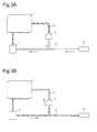
Fig. 3A is a schematic diagram showing the state of additive and air in the main passage and the return passage according to the first embodiment during execution of retrieval control; -
Fig. 3B is a schematic diagram showing a state during execution of the filling control with the addition valve closed; -
Fig. 4A is a schematic diagram showing the state of additive and air in the main passage and the return passage of the first embodiment during execution of the filling control with the addition valve open; -
Fig. 4B is a schematic diagram showing a state during execution of normal injection; -
Fig. 5 is a flowchart showing a procedure for filling control according to a second embodiment; -
Fig. 6A is a schematic diagram showing the state of additive and air in a main passage and a return passage according to a conventional art during execution of normal injection; -
Fig. 6B is a schematic diagram showing a state during execution of retrieval control; and -
Fig. 6C is a schematic diagram showing a state during execution of filling control. - A control device for an additive supply system according to a first embodiment of the present invention will be described with reference to
Figs. 1 to 5 . The control device is applied to an exhaust purifying device for a diesel engine. - As shown in
Fig. 1 , a selective reduction catalyst (hereinafter called a catalyst 8) is provided in anexhaust passage 7 of the diesel engine. An additive supply system is provided that supplies liquid additive in atank 1 by injection through anaddition valve 6 to thecatalyst 8 from the upstream side of thecatalyst 8. In the present embodiment, urea aqueous solution is used as the additive. - The configuration of the additive supply system will be described next.
- The
tank 1 and theaddition valve 6 are connected through amain passage 2. Anelectric pump 4 that feeds the additive under pressure is located in themain passage 2. Thepump 4 has an output shaft, of which the rotational direction is changed, so that the direction in which the additive is discharged from thepump 4 is changed. Specifically, while the output shaft of thepump 4 is rotated forward, the additive in thetank 1 is discharged toward theaddition valve 6. While the output shaft is rotated in reverse, the additive existing in a part closer to theaddition valve 6 than thepump 4 is discharged toward thetank 1. - A
return passage 3 branches off a part of themain passage 2 closer to theaddition valve 6 than thepump 4. Thereturn passage 3 has an end connected to thetank 1. Acheck valve 5 is located in thereturn passage 3. Thecheck valve 5 prevents flow of the additive from thereturn passage 3 into themain passage 2 and is opened if the pressure in themain passage 2 is higher than or equal to a predetermined valve opening pressure. Thecheck valve 5 maintains the pressure in themain passage 2 to be lower than or equal to the predetermined valve opening pressure. - An
electronic control device 10 functioning as the control device is responsible for various controls of the diesel engine including driving control of thepump 4 and injection control of the additive through theaddition valve 6. Theelectronic control device 10 includes a central processing unit (CPU), which performs calculations relating to the various controls, a read-only memory (ROM), in which programs, data or the like for these controls are stored, and a random access memory (RAM), which temporarily stores results of the calculations, for example. Theelectronic control device 10 reads signals detected by various sensors, performs various calculations, and controls thepump 4, theaddition valve 6 and others in a centralized manner based on results of these calculations. - The various sensors include known sensors used to determine the operating state of the engine and an
ignition switch 13. These sensors include a pressure sensor 11, which detects a pressure P of the additive in themain passage 2, and atemperature sensor 12, which detects a temperature T of the additive in themain passage 2. The pressure sensor 11 and thetemperature sensor 12 are provided in themain passage 2 on a side closer to theaddition valve 6 than the part of themain passage 2 where thereturn passage 3 branches off. - As described above, the additive in the piping that forms the
main passage 2 and thereturn passage 3 may be frozen while the engine is in a stopped state. This can damage the piping. - In the present embodiment, the
pump 4 is rotated in reverse to execute retrieval control of drawing the additive in themain passage 2 back into thetank 1 when the engine is stopped, thereby reducing damage on the piping due to freezing of the additive. - If the engine is restarted after execution of the retrieval control to supply the additive by injection, filling control of filling the
main passage 2 with the additive is executed before the injection of the additive. When the filling control is executed, thepump 4 is rotated forward while theaddition valve 6 is kept closed. Then, theaddition valve 6 is opened and thepump 4 is rotated forward. This restrains air from remaining in thereturn passage 3 and themain passage 2, thereby suppressing unstable injection of the additive after refilling of the additive. - A procedure for the filling control according to the first embodiment is described below by referring to the flowchart of
Fig. 2 . Theelectronic control device 10 repeats a series of processes shown inFig. 2 at predetermined intervals (at intervals of several tens of milliseconds, for example) while the engine operates. - As shown in
Fig. 2 , in this series of processes, it is determined first whether a pump drive permission flag Fp is at OFF (step S1). The flag Fp is initially set at OFF. - If the pump drive permission flag Fp is determined to be at OFF in step S1, the procedure proceeds to step S2 to determine whether a filling control permission flag Ff is at ON (step S2). The flag Ff is initially set at OFF. The flag Ff is set to ON if the temperature T of the additive is determined to be higher than a predetermined temperature that indicates that the additive is not frozen.
- If the filling control permission flag Ff is not determined to be at ON (step S2: NO), it is determined that a condition for executing the filling control is not satisfied. In this case, the series of processes is temporarily suspended.
- If the filling control permission flag Ff is determined to be at ON (step S2: YES), it is determined that the condition for executing the filling control is satisfied. Then, the procedure proceeds to step S3 to set the pump drive permission flag Fp to ON. This drives the
pump 4 to rotate forward. The rotation speed of thepump 4 is set at a level that causes the pressure of the additive discharged from thepump 4 to be higher than or equal to than the valve opening pressure of thecheck valve 5. - Next, the procedure proceeds to step S4 to count up a period Δtp elapsed from when the filling control was started. Next, the procedure proceeds to step S5 to determine whether the elapsed period Δtp is longer than a predetermined period α. This predetermined period α is set to be longer than or equal to the shortest period required for filling of the
return passage 3 with the additive to complete after the filling control is started with the rotation speed of thepump 4 set at the aforementioned level. The predetermined period α is set in advance based on the volume of thereturn passage 3. - If the elapsed period Δtp is determined to be shorter than or equal to the predetermined period α in step S5 (step S5: NO), it is determined that air still remains in the
return passage 3. In this case, the series of processes is temporarily suspended. - If the pump drive permission flag Fp is determined to be at ON in step S1 (step S1: NO), the procedure proceeds to step S6 to determine whether an addition valve opening permission flag Fv is at ON. The flag Fv is initially set at OFF.
- If the addition valve opening permission flag Fv is determined to be at OFF in step S6 (step S6: NO), the procedure proceeds to step S4 to count up the period Δtp elapsed from when the filling control was started. Next, the procedure proceeds to step S5. If the elapsed period Δtp is determined to be longer than the predetermined period α in step S5 (step S5: YES), the procedure proceeds to step S7 to set the addition valve opening permission flag Fv to ON. As a result, the
addition valve 6 is opened. - Next, the procedure proceeds to step S8 to count up a period Δtv elapsed from when the
addition valve 6 was opened. Next, the procedure proceeds to step S9 to determine whether the elapsed period Δtv is longer than a reference period β. This reference period β is set to be longer than or equal to the shortest period required for filling of themain passage 2 with the additive to complete after theaddition valve 6 is opened with the rotation speed of thepump 4 set at the aforementioned level. The reference period β is set in advance based on the volume of themain passage 2. - If the elapsed period Δtv is determined to be shorter than or equal to the reference period β in step S9 (step S9: NO), it is determined that air still remains in the
main passage 2. In this case, the series of processes is temporarily suspended. - If the pump drive permission flag Fp is determined to be at ON in step S1 (step S1: NO) and if the addition valve opening permission flag Fv is determined to be at ON in step S6 (step S6: YES), the procedure proceeds to step S8 to count up the period Δtv elapsed from when the
addition valve 6 was opened. Next, the procedure proceeds to step S9. If the elapsed period Δtv is determined to be longer than the reference period β in step S9 (step S9: YES), the procedure proceeds to step S10 to set the addition valve opening permission flag Fv to OFF. This closes theaddition valve 6 to finish the series of processes once. - Operation of the present embodiment will now be described by referring to
Figs. 3 and4 . InFigs. 3 and4 , a part of themain passage 2 and a part of thereturn passage 3 full of the additive are hatched, whereas a part of themain passage 2 and a part of thereturn passage 3 full of air are blank. - The retrieval control is executed when the
ignition switch 13 is turned off to stop the engine. This drives thepump 4 to rotate in reverse to draw the additive in themain passage 2 back into thetank 1, as shown inFig. 3A . As a result, the additive having existed in a part of themain passage 2 between thepump 4 and theaddition valve 6 and in a part of thereturn passage 3 closer to themain passage 2 than thecheck valve 5 is drawn back toward thetank 1, so that these parts become full of air. - Next, the
ignition switch 13 is turned on to restart the engine. If the additive is determined not to be frozen, the filling control is executed accordingly. In this case, as shown inFig. 3B , thepump 4 is driven to rotate forward first with theaddition valve 6 kept closed for the predetermined period α. At this time, theaddition valve 6 is closed, so that the additive discharged from thepump 4 flows into thereturn passage 3. This increases the pressure in thereturn passage 3 to open thecheck valve 5. As a result, air remaining in thereturn passage 3 is pushed out toward thetank 1 through thecheck valve 5. - After the air in the
return passage 3 is pushed out in this way and thereturn passage 3 becomes full of the additive, theaddition valve 6 is opened and thepump 4 is driven to rotate forward for the reference period β. This fills a part of themain passage 2 with the additive closer to theaddition valve 6 than the part of themain passage 2 where thereturn passage 3 branches off as shown inFig. 4A , thereby pushing out air remaining in themain passage 2 toward theexhaust passage 7 through theaddition valve 6. - Thus, executing the filling control of the present embodiment reliably restrains air from remaining in the
return passage 3 and themain passage 2. - As shown in
Fig. 4B , air remaining in themain passage 2 and thereturn passage 3 is reduced when the additive is supplied by injection through theaddition valve 6 thereafter. This suppresses fluctuation of the pressure in themain passage 2, so that fluctuation of the rotation of thepump 4 is reliably suppressed. - The control device for an additive supply system of the present embodiment achieves the following advantages (1) to (3).
- (1) When executing the filling control of filling the
main passage 2 with the additive after execution of the retrieval control, theelectronic control device 10 rotates thepump 4 forward while keeping theaddition valve 6 open. Then, theelectronic control device 10 opens theaddition valve 6 and rotates thepump 4 forward. In this control, air remaining in thereturn passage 3 is pushed out through thecheck valve 5 while theaddition valve 6 is closed. In response to opening of theaddition valve 6 thereafter, air remaining in themain passage 2 is pushed out through theaddition valve 6. This can reliably restrain air from remaining in thereturn passage 3 and themain passage 2, thereby reliably suppressing unstable injection of the additive to occur after refilling of the additive. - (2) When executing the filling control, the
electronic control device 10 drives thepump 4 to rotate forward while keeping theaddition valve 6 closed for the predetermined period α set in advance. The predetermined period α is set to be longer than or equal to the shortest period required for filling of thereturn passage 3 with the additive to complete after the filling control is started. In this control, a period when thepump 4 is driven to rotate forward while theaddition valve 6 is kept closed can be controlled easily during execution of the filling control. In the aforementioned control, theaddition valve 6 is opened after thereturn passage 3 becomes full of the additive, specifically after substantially all air remaining in thereturn passage 3 is pushed out through thecheck valve 5. This reliably restrains air from remaining in thereturn passage 3 after refilling of the additive. - (3) When executing the filling control, the
electronic control device 10 drives thepump 4 to rotate forward while keeping theaddition valve 6 open for the reference period β set in advance. The reference period β is set to be longer than or equal to the shortest period required for filling of themain passage 2 with the additive to complete after theaddition valve 6 is opened. In this control, a period when thepump 4 is driven to rotate forward while theaddition valve 6 is kept open can be controlled easily during execution of the filling control. In the aforementioned control, the additive is supplied by injection through theaddition valve 6 after substantially all air remaining in themain passage 2 is pushed out through theaddition valve 6. This reliably restrains air from remaining in themain passage 2 after refilling of the additive. - A second embodiment of the present invention will now be described with reference to
Fig. 5 . - During execution of the filling control, air of a larger amount existing in the
main passage 2 immediately after theaddition valve 6 is opened causes the pressure P in themain passage 2 to change within a lower pressure range than when a smaller amount of air exists in themain passage 2. Thus, if the reference period β is fixed like in the control of the first embodiment and if the pressure in themain passage 2 changes within a lower pressure range than expected, the reference period β may elapse and the filling control may be finished while part of air in themain passage 2 remains without being pushed out. In this case, it may be impossible to start injection of the additive in a desirable manner. - When executing the filling control, the
electronic control device 10 of the present embodiment operates such that the lower the range within which the pressure in themain passage 2 changes after theaddition valve 6 is opened, the longer the period in which thepump 4 is driven to rotate forward with theaddition valve 6 kept open. - More specifically, the
pump 4 is driven to rotate forward while theaddition valve 6 is kept open until the relationship shown in the following expression (1) is established after theaddition valve 6 is opened.
- The expression (1) will be explained below.
- The expression (3) is obtained by entering parameters relating to the additive flowing in the
main passage 2 into the equation of motion shown in the expression (2).

- The sign V represents the volume of the
main passage 2, and the sign ε represents the specific gravity of the additive. Further, the sign Spd represents the filling speed of the additive, and the sign t represents the period elapsed after theaddition valve 6 is opened. The expression (3) is time-integrated to obtain the following expression (4).
- The product of the volume V of the
main passage 2 and the specific gravity ε of the additive means a mass M of this additive filling the entiremain passage 2. Both sides of the expression (4) are divided by S to obtain the following expression (5).
- The parameters on the right side of the expression (5) except log (t) can be considered as fixed values. Defining the product of these parameters as γ, both sides of the expression (5) are divided by log(t), thereby obtaining the following expression (6).

- The value on the left side of the expression (6) is derived through the
electronic control device 10 in each predetermined period from when theaddition valve 6 is opened during execution of the filling control. The relationship shown in the expression (6) is established with "t" that indicates a period required for themain passage 2 to become full of the additive. Thus, based on the value on the left side being greater than or equal to γ, it can be determined that themain passage 2 is entirely filled with the additive, specifically that substantially all air remaining in themain passage 2 has been pushed out to theexhaust passage 7 through theaddition valve 6. - A procedure for the filling control according to the second embodiment is described below by referring to the flowchart of
Fig. 5 . Theelectronic control device 10 repeats a series of processes shown inFig. 5 at predetermined intervals (at intervals of several tens of milliseconds, for example) while the engine operates. In this flowchart, the processes from S101 t S107 are the same as those from steps S1 to S7 ofFig. 2 . Thus, the following description is mainly intended for a difference and overlapping description will not be given. - As shown in
Fig. 5 , if the addition valve opening permission flag Fv is set to ON to open theaddition valve 6 in step S107, the procedure proceeds to step S108 to read the pressure P in themain passage 2 at the time. Next, the procedure proceeds to step S109 to calculate the left side of the expression (1). Next, the procedure proceeds to step S110 to determine whether the expression (1) is satisfied. - If the expression (1) is determined not to be satisfied in step S110 (step S110: NO), it is determined that air still remains in the
main passage 2. In this case, the series of processes is temporarily suspended. - If the pump drive permission flag Fp is determined to be at ON in step S101 (step S101: NO) and if the addition valve opening permission flag Fv is determined to be at ON in step S106 (step S106: YES), the procedure proceeds to steps S108 and S109 to calculate the left side of the expression (1) again. Then, if the relationship shown in the expression (1) is determined to be established in step S110 (step S110: YES), the procedure proceeds to step S111 to set the addition valve opening permission flag Fv to OFF. As a result, the
addition valve 6 is closed to finish the filling control, so that the series of processes is temporarily suspended. - The control device for an additive supply system of the present embodiment achieves the following advantage (4) in addition to the advantage (1) achieved by the first embodiment.
- (4) When executing the filling control, the
electronic control device 10 operates such that the lower the range within which the pressure P in themain passage 2 changes after theaddition valve 6 is opened, the longer the period in which thepump 4 is driven to rotate forward with theaddition valve 6 kept open. More specifically, thepump 4 is driven to rotate forward while theaddition valve 6 is kept open until the relationship shown in the expression (1) is established. In this control, timing of finishing the filling control is set variably in response to how the pressure P in themain passage 2 actually changes. Thus, even if the pressure P in themain passage 2 changes within a lower pressure range than expected, this can prevent the filling control from being finished with part of air in themain passage 2 remaining without being pushed out. This reliably restrains air from remaining in the main passage after refilling of the additive. - The control device for an additive supply system of the present invention is not limited to the configurations shown as examples in the above illustrated embodiments. Where appropriate, the control device may be changed and implemented as follows, for example.
- In each of the above illustrated embodiments, the
addition valve 6 is kept closed until the period Δtp elapsed from when the filling control was started becomes longer than the predetermined period α. - Air of a larger amount existing in the
main passage 2 or thereturn passage 3 immediately after start of the filling control increases the pressure in themain passage 2 more slowly than air of a smaller amount, thereby delaying timing of opening thecheck valve 5. Thus, if the pressure in themain passage 2 increases at a lower speed than expected in the control of each of the above illustrated embodiments, where the predetermined period α in which theaddition valve 6 should be kept closed is set in advance, the predetermined period α might elapse and theaddition valve 6 might be opened while part of air in themain passage 2 remains without being pushed out. - In this regard, when the filling control is executed, the
pump 4 may be driven to rotate forward while theaddition valve 6 is kept closed for a predetermined period τ from when the pressure P in themain passage 2 became higher than or equal to the valve opening pressure of thecheck valve 5. In this case, the pressure P in themain passage 2 actually increases to the valve opening pressure of thecheck valve 5. Then, a period elapsed from when thecheck valve 5 is opened is controlled. Thus, theaddition valve 6 is kept closed until air remaining in thereturn passage 3 is pushed out through thecheck valve 5. This reliably restrains air from remaining in thereturn passage 3 after refilling of the additive. -
- 1, 101
- Tank
- 2, 102
- Main passage
- 3, 103
- Return passage
- 4, 104
- Pump
- 5, 105
- Check valve
- 6, 106
- Addition valve
- 7
- Exhaust passage
- 8
- Catalyst
- 10
- Electronic control device
- 11
- Pressure sensor
- 12
- Temperature sensor
- 13
- Ignition switch
Claims (5)
- A control device for an additive supply system, wherein the additive supply system includes:a tank that stores an additive in a liquid form;an addition valve through which the additive in the tank is supplied by injection to a catalyst provided in an exhaust passage of an internal combustion engine;a main passage through which the additive in the tank is supplied to the addition valve;a pump provided in the main passage, wherein the pump feeds the additive under pressure;a return passage branching off the main passage to be connected to the tank; anda check valve provided in the return passage, wherein the check valve prevents flow of the additive from the return passage into the main passage, and the check valve is opened if a pressure in the main passage becomes higher than or equal to a predetermined valve opening pressure, the control device being characterized in thatthe control device is configured to be capable of executing retrieval control of drawing the additive in the main passage back into the tank by rotating the pump in reverse, andwhen executing filling control of filling the main passage with the additive after execution of the retrieval control, the control device rotates the pump forward while keeping the addition valve closed, and then opens the addition valve and rotates the pump forward.
- The control device for an additive supply system according to claim 1, wherein
when executing the filling control, the control device drives the pump to rotate forward while keeping the addition valve closed for a predetermined period set in advance, and
the predetermined period is set to be longer than or equal to the shortest period required for filling of the return passage with the additive to complete after the filling control is started. - The control device for an additive supply system according to claim 1 or 2, wherein
when executing the filling control, the control device drives the pump, after rotating the pump forward while keeping the addition valve closed, to rotate forward while keeping the addition valve open for a reference period set in advance, and
the reference period is set to be longer than or equal to the shortest period required for filling of the main passage with the additive to complete after the addition valve is opened. - The control device for an additive supply system according to claim 1 or 2, wherein, when the control device executes the filling control, the lower the range within which the pressure in the main passage changes, the longer becomes the period in which the control device drives the pump to rotate forward while the addition valve is kept open after the pump rotates forward while the addition valve is kept closed.
- The control device for an additive supply system according to claim 4, wherein, when executing the filling control, the control device drives the pump to rotate forward while keeping the addition valve open until a relationship represented by the following expression is established:

where t represents the period elapsed after the addition valve is opened, M represents the mass of the additive filling the entire main passage, S represents the cross-sectional area of the main passage, Spd represents the filling speed of the additive, and P represents the pressure in the main passage.
Applications Claiming Priority (1)
| Application Number | Priority Date | Filing Date | Title |
|---|---|---|---|
| PCT/JP2012/073065 WO2014038084A1 (en) | 2012-09-10 | 2012-09-10 | Control device for additive supply systems |
Publications (3)
| Publication Number | Publication Date |
|---|---|
| EP2905441A1 true EP2905441A1 (en) | 2015-08-12 |
| EP2905441A4 EP2905441A4 (en) | 2016-07-06 |
| EP2905441B1 EP2905441B1 (en) | 2017-11-15 |
Family
ID=50236730
Family Applications (1)
| Application Number | Title | Priority Date | Filing Date |
|---|---|---|---|
| EP12884320.8A Not-in-force EP2905441B1 (en) | 2012-09-10 | 2012-09-10 | Control device for additive supply systems |
Country Status (3)
| Country | Link |
|---|---|
| EP (1) | EP2905441B1 (en) |
| JP (1) | JP5748026B2 (en) |
| WO (1) | WO2014038084A1 (en) |
Cited By (5)
| Publication number | Priority date | Publication date | Assignee | Title |
|---|---|---|---|---|
| GB2546764A (en) * | 2016-01-28 | 2017-08-02 | Delphi Int Operations Luxembourg Sarl | Selective catalytic reduction dosing sytem |
| US10309282B2 (en) | 2014-12-11 | 2019-06-04 | Komatsu Ltd. | Reducing agent supply device and method for controlling reducing agent supply device |
| CN110374727A (en) * | 2019-09-03 | 2019-10-25 | 湖北农谷环保科技有限公司 | Urea injection system for diesel engine aftertreatment system |
| EP3581774A1 (en) * | 2018-06-11 | 2019-12-18 | Robert Bosch GmbH | First fill function triggering control module and method for vehicle scr system |
| GB2576925A (en) * | 2018-09-07 | 2020-03-11 | Delphi Tech Ip Ltd | A pump module for a dosing system and a non-return valve assembly therefor |
Families Citing this family (5)
| Publication number | Priority date | Publication date | Assignee | Title |
|---|---|---|---|---|
| JP6162747B2 (en) * | 2015-05-28 | 2017-07-12 | トヨタ自動車株式会社 | Additive supply device |
| US9677444B2 (en) | 2015-08-19 | 2017-06-13 | Caterpillar Inc. | Reductant supply system |
| JP7013820B2 (en) * | 2017-11-29 | 2022-02-01 | 株式会社デンソー | Reducing agent addition system |
| JP7010003B2 (en) * | 2018-01-09 | 2022-01-26 | 株式会社デンソー | Injection control device |
| CN114215629B (en) * | 2021-12-02 | 2023-01-31 | 江铃汽车股份有限公司 | Emptying method of electronic control type urea injection system |
Family Cites Families (7)
| Publication number | Priority date | Publication date | Assignee | Title |
|---|---|---|---|---|
| DE502004010210D1 (en) * | 2004-12-30 | 2009-11-19 | Grundfos Nonox As | metering pump |
| JP4730278B2 (en) | 2006-10-20 | 2011-07-20 | 株式会社デンソー | Engine exhaust purification system |
| FR2921911A1 (en) * | 2007-09-21 | 2009-04-10 | Inergy Automotive Systems Res | SYSTEM FOR STORING AND INJECTING AN ADDITIVE SOLUTION IN EXHAUST GASES OF AN ENGINE. |
| JP4911193B2 (en) * | 2009-04-28 | 2012-04-04 | 株式会社デンソー | Exhaust gas purification system for internal combustion engine |
| JP5093691B2 (en) * | 2009-06-12 | 2012-12-12 | トヨタ自動車株式会社 | Abnormality diagnosis device for reducing agent supply system |
| US9145817B2 (en) * | 2010-11-08 | 2015-09-29 | Bosch Corporation | Reducing agent injection valve abnormality detection unit and reducing agent supply apparatus |
| JP2012127214A (en) * | 2010-12-13 | 2012-07-05 | Bosch Corp | Reducing agent supplying system, and exhaust gas purifying system of internal combustion engine |
-
2012
- 2012-09-10 EP EP12884320.8A patent/EP2905441B1/en not_active Not-in-force
- 2012-09-10 WO PCT/JP2012/073065 patent/WO2014038084A1/en not_active Ceased
- 2012-09-10 JP JP2014534140A patent/JP5748026B2/en not_active Expired - Fee Related
Cited By (9)
| Publication number | Priority date | Publication date | Assignee | Title |
|---|---|---|---|---|
| US10309282B2 (en) | 2014-12-11 | 2019-06-04 | Komatsu Ltd. | Reducing agent supply device and method for controlling reducing agent supply device |
| GB2546764A (en) * | 2016-01-28 | 2017-08-02 | Delphi Int Operations Luxembourg Sarl | Selective catalytic reduction dosing sytem |
| GB2546764B (en) * | 2016-01-28 | 2019-04-10 | Delphi Tech Ip Ltd | Selective catalytic reduction dosing sytem |
| US10662848B2 (en) | 2016-01-28 | 2020-05-26 | Delphi Technologies Ip Limited | SCR dosing system |
| EP3581774A1 (en) * | 2018-06-11 | 2019-12-18 | Robert Bosch GmbH | First fill function triggering control module and method for vehicle scr system |
| GB2576925A (en) * | 2018-09-07 | 2020-03-11 | Delphi Tech Ip Ltd | A pump module for a dosing system and a non-return valve assembly therefor |
| GB2576925B (en) * | 2018-09-07 | 2021-01-06 | Delphi Tech Ip Ltd | A pump module for a dosing system and a non-return valve assembly therefor |
| CN110374727A (en) * | 2019-09-03 | 2019-10-25 | 湖北农谷环保科技有限公司 | Urea injection system for diesel engine aftertreatment system |
| CN110374727B (en) * | 2019-09-03 | 2024-05-31 | 武汉洛特福动力技术有限公司 | Urea injection system for diesel engine aftertreatment system |
Also Published As
| Publication number | Publication date |
|---|---|
| JP5748026B2 (en) | 2015-07-15 |
| JPWO2014038084A1 (en) | 2016-08-08 |
| EP2905441A4 (en) | 2016-07-06 |
| WO2014038084A1 (en) | 2014-03-13 |
| EP2905441B1 (en) | 2017-11-15 |
Similar Documents
| Publication | Publication Date | Title |
|---|---|---|
| EP2905441B1 (en) | Control device for additive supply systems | |
| RU2752523C2 (en) | System and method for cleaning exhaust system liquid injector of diesel engine | |
| JP5139765B2 (en) | Control device and control method for reducing agent supply system | |
| EP2085596A2 (en) | Fuel injector for internal combustion engine | |
| US8141346B2 (en) | System and method for monitoring reductant quality | |
| EP2730762B1 (en) | Reducing agent supply device and exhaust gas purification apparatus for internal combustion engine | |
| US20090293459A1 (en) | Exhaust gas purification device of internal combustion engine | |
| JP2008180193A (en) | Clogging determination device for reducing agent injection valve and clogging determination method for reducing agent injection valve | |
| US11131228B2 (en) | Method for preventing a risk of freezing in a reducing-agent feeding device of a selective catalytic reduction system | |
| DE102016117949A1 (en) | diagnostic device | |
| US10844768B2 (en) | Abnormality determination device | |
| EP3219946A1 (en) | Urea water injection system and method for preventing crystallization in urea water injection device | |
| JP2009174383A (en) | Liquid supply device | |
| WO2014061377A1 (en) | Reducing agent recovery control method, reducing agent supply device, and electronic control device | |
| US8789358B2 (en) | Selective catalytic reduction catalyst ammonia storage control systems and methods | |
| CN103982278B (en) | Method and apparatus for determining the amount for being available for domination of material in a reservoir | |
| EP3106639B1 (en) | Reductant supply system | |
| EP2754871A1 (en) | Method and device for controlling the operation of an exhaust aftertreatment system in a vehicle | |
| JP6017866B2 (en) | Reducing agent supply device, liquid reducing agent recovery control method, and exhaust purification device | |
| EP2754867B1 (en) | Warm-up system for exhaust system of internal combustion engine | |
| US10954840B2 (en) | Def injection strategy for multiple injection systems | |
| US20130091826A1 (en) | Cold start no2 generation system | |
| US20180363524A1 (en) | Urea scr system | |
| EP2940264B1 (en) | Method for controlling reductant supply device, and reductant supply device | |
| JP2015151978A (en) | Controller for exhaust emission control device |
Legal Events
| Date | Code | Title | Description |
|---|---|---|---|
| PUAI | Public reference made under article 153(3) epc to a published international application that has entered the european phase |
Free format text: ORIGINAL CODE: 0009012 |
|
| 17P | Request for examination filed |
Effective date: 20150310 |
|
| AK | Designated contracting states |
Kind code of ref document: A1 Designated state(s): AL AT BE BG CH CY CZ DE DK EE ES FI FR GB GR HR HU IE IS IT LI LT LU LV MC MK MT NL NO PL PT RO RS SE SI SK SM TR |
|
| AX | Request for extension of the european patent |
Extension state: BA ME |
|
| DAX | Request for extension of the european patent (deleted) | ||
| RA4 | Supplementary search report drawn up and despatched (corrected) |
Effective date: 20160608 |
|
| RIC1 | Information provided on ipc code assigned before grant |
Ipc: F01N 3/08 20060101AFI20160602BHEP Ipc: F01N 3/20 20060101ALI20160602BHEP |
|
| GRAP | Despatch of communication of intention to grant a patent |
Free format text: ORIGINAL CODE: EPIDOSNIGR1 |
|
| STAA | Information on the status of an ep patent application or granted ep patent |
Free format text: STATUS: GRANT OF PATENT IS INTENDED |
|
| INTG | Intention to grant announced |
Effective date: 20170104 |
|
| GRAJ | Information related to disapproval of communication of intention to grant by the applicant or resumption of examination proceedings by the epo deleted |
Free format text: ORIGINAL CODE: EPIDOSDIGR1 |
|
| GRAP | Despatch of communication of intention to grant a patent |
Free format text: ORIGINAL CODE: EPIDOSNIGR1 |
|
| INTG | Intention to grant announced |
Effective date: 20170104 |
|
| GRAS | Grant fee paid |
Free format text: ORIGINAL CODE: EPIDOSNIGR3 |
|
| GRAJ | Information related to disapproval of communication of intention to grant by the applicant or resumption of examination proceedings by the epo deleted |
Free format text: ORIGINAL CODE: EPIDOSDIGR1 |
|
| GRAP | Despatch of communication of intention to grant a patent |
Free format text: ORIGINAL CODE: EPIDOSNIGR1 |
|
| INTG | Intention to grant announced |
Effective date: 20170602 |
|
| GRAS | Grant fee paid |
Free format text: ORIGINAL CODE: EPIDOSNIGR3 |
|
| GRAA | (expected) grant |
Free format text: ORIGINAL CODE: 0009210 |
|
| STAA | Information on the status of an ep patent application or granted ep patent |
Free format text: STATUS: THE PATENT HAS BEEN GRANTED |
|
| AK | Designated contracting states |
Kind code of ref document: B1 Designated state(s): AL AT BE BG CH CY CZ DE DK EE ES FI FR GB GR HR HU IE IS IT LI LT LU LV MC MK MT NL NO PL PT RO RS SE SI SK SM TR |
|
| REG | Reference to a national code |
Ref country code: CH Ref legal event code: EP Ref country code: GB Ref legal event code: FG4D Ref country code: AT Ref legal event code: REF Ref document number: 946514 Country of ref document: AT Kind code of ref document: T Effective date: 20171115 |
|
| REG | Reference to a national code |
Ref country code: IE Ref legal event code: FG4D |
|
| REG | Reference to a national code |
Ref country code: DE Ref legal event code: R096 Ref document number: 602012039961 Country of ref document: DE |
|
| REG | Reference to a national code |
Ref country code: NL Ref legal event code: MP Effective date: 20171115 |
|
| REG | Reference to a national code |
Ref country code: LT Ref legal event code: MG4D |
|
| REG | Reference to a national code |
Ref country code: AT Ref legal event code: MK05 Ref document number: 946514 Country of ref document: AT Kind code of ref document: T Effective date: 20171115 |
|
| PG25 | Lapsed in a contracting state [announced via postgrant information from national office to epo] |
Ref country code: SE Free format text: LAPSE BECAUSE OF FAILURE TO SUBMIT A TRANSLATION OF THE DESCRIPTION OR TO PAY THE FEE WITHIN THE PRESCRIBED TIME-LIMIT Effective date: 20171115 Ref country code: ES Free format text: LAPSE BECAUSE OF FAILURE TO SUBMIT A TRANSLATION OF THE DESCRIPTION OR TO PAY THE FEE WITHIN THE PRESCRIBED TIME-LIMIT Effective date: 20171115 Ref country code: FI Free format text: LAPSE BECAUSE OF FAILURE TO SUBMIT A TRANSLATION OF THE DESCRIPTION OR TO PAY THE FEE WITHIN THE PRESCRIBED TIME-LIMIT Effective date: 20171115 Ref country code: NO Free format text: LAPSE BECAUSE OF FAILURE TO SUBMIT A TRANSLATION OF THE DESCRIPTION OR TO PAY THE FEE WITHIN THE PRESCRIBED TIME-LIMIT Effective date: 20180215 Ref country code: NL Free format text: LAPSE BECAUSE OF FAILURE TO SUBMIT A TRANSLATION OF THE DESCRIPTION OR TO PAY THE FEE WITHIN THE PRESCRIBED TIME-LIMIT Effective date: 20171115 Ref country code: LT Free format text: LAPSE BECAUSE OF FAILURE TO SUBMIT A TRANSLATION OF THE DESCRIPTION OR TO PAY THE FEE WITHIN THE PRESCRIBED TIME-LIMIT Effective date: 20171115 |
|
| PG25 | Lapsed in a contracting state [announced via postgrant information from national office to epo] |
Ref country code: RS Free format text: LAPSE BECAUSE OF FAILURE TO SUBMIT A TRANSLATION OF THE DESCRIPTION OR TO PAY THE FEE WITHIN THE PRESCRIBED TIME-LIMIT Effective date: 20171115 Ref country code: HR Free format text: LAPSE BECAUSE OF FAILURE TO SUBMIT A TRANSLATION OF THE DESCRIPTION OR TO PAY THE FEE WITHIN THE PRESCRIBED TIME-LIMIT Effective date: 20171115 Ref country code: LV Free format text: LAPSE BECAUSE OF FAILURE TO SUBMIT A TRANSLATION OF THE DESCRIPTION OR TO PAY THE FEE WITHIN THE PRESCRIBED TIME-LIMIT Effective date: 20171115 Ref country code: AT Free format text: LAPSE BECAUSE OF FAILURE TO SUBMIT A TRANSLATION OF THE DESCRIPTION OR TO PAY THE FEE WITHIN THE PRESCRIBED TIME-LIMIT Effective date: 20171115 Ref country code: BG Free format text: LAPSE BECAUSE OF FAILURE TO SUBMIT A TRANSLATION OF THE DESCRIPTION OR TO PAY THE FEE WITHIN THE PRESCRIBED TIME-LIMIT Effective date: 20180215 Ref country code: GR Free format text: LAPSE BECAUSE OF FAILURE TO SUBMIT A TRANSLATION OF THE DESCRIPTION OR TO PAY THE FEE WITHIN THE PRESCRIBED TIME-LIMIT Effective date: 20180216 |
|
| REG | Reference to a national code |
Ref country code: DE Ref legal event code: R084 Ref document number: 602012039961 Country of ref document: DE |
|
| REG | Reference to a national code |
Ref country code: GB Ref legal event code: 746 Effective date: 20180625 |
|
| PG25 | Lapsed in a contracting state [announced via postgrant information from national office to epo] |
Ref country code: EE Free format text: LAPSE BECAUSE OF FAILURE TO SUBMIT A TRANSLATION OF THE DESCRIPTION OR TO PAY THE FEE WITHIN THE PRESCRIBED TIME-LIMIT Effective date: 20171115 Ref country code: CY Free format text: LAPSE BECAUSE OF FAILURE TO SUBMIT A TRANSLATION OF THE DESCRIPTION OR TO PAY THE FEE WITHIN THE PRESCRIBED TIME-LIMIT Effective date: 20171115 Ref country code: DK Free format text: LAPSE BECAUSE OF FAILURE TO SUBMIT A TRANSLATION OF THE DESCRIPTION OR TO PAY THE FEE WITHIN THE PRESCRIBED TIME-LIMIT Effective date: 20171115 Ref country code: SK Free format text: LAPSE BECAUSE OF FAILURE TO SUBMIT A TRANSLATION OF THE DESCRIPTION OR TO PAY THE FEE WITHIN THE PRESCRIBED TIME-LIMIT Effective date: 20171115 Ref country code: CZ Free format text: LAPSE BECAUSE OF FAILURE TO SUBMIT A TRANSLATION OF THE DESCRIPTION OR TO PAY THE FEE WITHIN THE PRESCRIBED TIME-LIMIT Effective date: 20171115 |
|
| REG | Reference to a national code |
Ref country code: FR Ref legal event code: PLFP Year of fee payment: 7 |
|
| REG | Reference to a national code |
Ref country code: DE Ref legal event code: R097 Ref document number: 602012039961 Country of ref document: DE |
|
| PG25 | Lapsed in a contracting state [announced via postgrant information from national office to epo] |
Ref country code: SM Free format text: LAPSE BECAUSE OF FAILURE TO SUBMIT A TRANSLATION OF THE DESCRIPTION OR TO PAY THE FEE WITHIN THE PRESCRIBED TIME-LIMIT Effective date: 20171115 Ref country code: PL Free format text: LAPSE BECAUSE OF FAILURE TO SUBMIT A TRANSLATION OF THE DESCRIPTION OR TO PAY THE FEE WITHIN THE PRESCRIBED TIME-LIMIT Effective date: 20171115 Ref country code: IT Free format text: LAPSE BECAUSE OF FAILURE TO SUBMIT A TRANSLATION OF THE DESCRIPTION OR TO PAY THE FEE WITHIN THE PRESCRIBED TIME-LIMIT Effective date: 20171115 Ref country code: RO Free format text: LAPSE BECAUSE OF FAILURE TO SUBMIT A TRANSLATION OF THE DESCRIPTION OR TO PAY THE FEE WITHIN THE PRESCRIBED TIME-LIMIT Effective date: 20171115 |
|
| PLBE | No opposition filed within time limit |
Free format text: ORIGINAL CODE: 0009261 |
|
| STAA | Information on the status of an ep patent application or granted ep patent |
Free format text: STATUS: NO OPPOSITION FILED WITHIN TIME LIMIT |
|
| 26N | No opposition filed |
Effective date: 20180817 |
|
| PG25 | Lapsed in a contracting state [announced via postgrant information from national office to epo] |
Ref country code: SI Free format text: LAPSE BECAUSE OF FAILURE TO SUBMIT A TRANSLATION OF THE DESCRIPTION OR TO PAY THE FEE WITHIN THE PRESCRIBED TIME-LIMIT Effective date: 20171115 |
|
| PG25 | Lapsed in a contracting state [announced via postgrant information from national office to epo] |
Ref country code: MC Free format text: LAPSE BECAUSE OF FAILURE TO SUBMIT A TRANSLATION OF THE DESCRIPTION OR TO PAY THE FEE WITHIN THE PRESCRIBED TIME-LIMIT Effective date: 20171115 |
|
| REG | Reference to a national code |
Ref country code: CH Ref legal event code: PL |
|
| REG | Reference to a national code |
Ref country code: BE Ref legal event code: MM Effective date: 20180930 |
|
| REG | Reference to a national code |
Ref country code: IE Ref legal event code: MM4A |
|
| PG25 | Lapsed in a contracting state [announced via postgrant information from national office to epo] |
Ref country code: LU Free format text: LAPSE BECAUSE OF NON-PAYMENT OF DUE FEES Effective date: 20180910 |
|
| PG25 | Lapsed in a contracting state [announced via postgrant information from national office to epo] |
Ref country code: IE Free format text: LAPSE BECAUSE OF NON-PAYMENT OF DUE FEES Effective date: 20180910 |
|
| PG25 | Lapsed in a contracting state [announced via postgrant information from national office to epo] |
Ref country code: CH Free format text: LAPSE BECAUSE OF NON-PAYMENT OF DUE FEES Effective date: 20180930 Ref country code: BE Free format text: LAPSE BECAUSE OF NON-PAYMENT OF DUE FEES Effective date: 20180930 Ref country code: LI Free format text: LAPSE BECAUSE OF NON-PAYMENT OF DUE FEES Effective date: 20180930 |
|
| PG25 | Lapsed in a contracting state [announced via postgrant information from national office to epo] |
Ref country code: MT Free format text: LAPSE BECAUSE OF NON-PAYMENT OF DUE FEES Effective date: 20180910 |
|
| PG25 | Lapsed in a contracting state [announced via postgrant information from national office to epo] |
Ref country code: TR Free format text: LAPSE BECAUSE OF FAILURE TO SUBMIT A TRANSLATION OF THE DESCRIPTION OR TO PAY THE FEE WITHIN THE PRESCRIBED TIME-LIMIT Effective date: 20171115 |
|
| PG25 | Lapsed in a contracting state [announced via postgrant information from national office to epo] |
Ref country code: PT Free format text: LAPSE BECAUSE OF FAILURE TO SUBMIT A TRANSLATION OF THE DESCRIPTION OR TO PAY THE FEE WITHIN THE PRESCRIBED TIME-LIMIT Effective date: 20171115 |
|
| PG25 | Lapsed in a contracting state [announced via postgrant information from national office to epo] |
Ref country code: MK Free format text: LAPSE BECAUSE OF NON-PAYMENT OF DUE FEES Effective date: 20171115 Ref country code: HU Free format text: LAPSE BECAUSE OF FAILURE TO SUBMIT A TRANSLATION OF THE DESCRIPTION OR TO PAY THE FEE WITHIN THE PRESCRIBED TIME-LIMIT; INVALID AB INITIO Effective date: 20120910 |
|
| PG25 | Lapsed in a contracting state [announced via postgrant information from national office to epo] |
Ref country code: AL Free format text: LAPSE BECAUSE OF FAILURE TO SUBMIT A TRANSLATION OF THE DESCRIPTION OR TO PAY THE FEE WITHIN THE PRESCRIBED TIME-LIMIT Effective date: 20171115 Ref country code: IS Free format text: LAPSE BECAUSE OF FAILURE TO SUBMIT A TRANSLATION OF THE DESCRIPTION OR TO PAY THE FEE WITHIN THE PRESCRIBED TIME-LIMIT Effective date: 20180315 |
|
| REG | Reference to a national code |
Ref country code: DE Ref legal event code: R081 Ref document number: 602012039961 Country of ref document: DE Owner name: KABUSHIKI KAISHA TOYOTA JIDOSHOKKI, KARIYA-SHI, JP Free format text: FORMER OWNER: TOYOTA JIDOSHA KABUSHIKI KAISHA, TOYOTA-SHI, AICHI-KEN, JP |
|
| PGFP | Annual fee paid to national office [announced via postgrant information from national office to epo] |
Ref country code: GB Payment date: 20220728 Year of fee payment: 11 |
|
| PGFP | Annual fee paid to national office [announced via postgrant information from national office to epo] |
Ref country code: FR Payment date: 20220808 Year of fee payment: 11 |
|
| P01 | Opt-out of the competence of the unified patent court (upc) registered |
Effective date: 20230519 |
|
| PGFP | Annual fee paid to national office [announced via postgrant information from national office to epo] |
Ref country code: DE Payment date: 20230802 Year of fee payment: 12 |
|
| GBPC | Gb: european patent ceased through non-payment of renewal fee |
Effective date: 20230910 |
|
| PG25 | Lapsed in a contracting state [announced via postgrant information from national office to epo] |
Ref country code: GB Free format text: LAPSE BECAUSE OF NON-PAYMENT OF DUE FEES Effective date: 20230910 |
|
| PG25 | Lapsed in a contracting state [announced via postgrant information from national office to epo] |
Ref country code: GB Free format text: LAPSE BECAUSE OF NON-PAYMENT OF DUE FEES Effective date: 20230910 Ref country code: FR Free format text: LAPSE BECAUSE OF NON-PAYMENT OF DUE FEES Effective date: 20230930 |
|
| REG | Reference to a national code |
Ref country code: DE Ref legal event code: R119 Ref document number: 602012039961 Country of ref document: DE |
|
| PG25 | Lapsed in a contracting state [announced via postgrant information from national office to epo] |
Ref country code: DE Free format text: LAPSE BECAUSE OF NON-PAYMENT OF DUE FEES Effective date: 20250401 |