EP2905223A1 - Variable hub-to-hub phasing rotor system - Google Patents
Variable hub-to-hub phasing rotor system Download PDFInfo
- Publication number
- EP2905223A1 EP2905223A1 EP14157931.8A EP14157931A EP2905223A1 EP 2905223 A1 EP2905223 A1 EP 2905223A1 EP 14157931 A EP14157931 A EP 14157931A EP 2905223 A1 EP2905223 A1 EP 2905223A1
- Authority
- EP
- European Patent Office
- Prior art keywords
- rotor
- aircraft
- rotor assembly
- phase
- control system
- Prior art date
- Legal status (The legal status is an assumption and is not a legal conclusion. Google has not performed a legal analysis and makes no representation as to the accuracy of the status listed.)
- Granted
Links
Images

Classifications
-
- B—PERFORMING OPERATIONS; TRANSPORTING
- B64—AIRCRAFT; AVIATION; COSMONAUTICS
- B64C—AEROPLANES; HELICOPTERS
- B64C27/00—Rotorcraft; Rotors peculiar thereto
- B64C27/001—Vibration damping devices
-
- B—PERFORMING OPERATIONS; TRANSPORTING
- B64—AIRCRAFT; AVIATION; COSMONAUTICS
- B64C—AEROPLANES; HELICOPTERS
- B64C11/00—Propellers, e.g. of ducted type; Features common to propellers and rotors for rotorcraft
- B64C11/46—Arrangements of, or constructional features peculiar to, multiple propellers
- B64C11/50—Phase synchronisation between multiple propellers
-
- B—PERFORMING OPERATIONS; TRANSPORTING
- B64—AIRCRAFT; AVIATION; COSMONAUTICS
- B64C—AEROPLANES; HELICOPTERS
- B64C27/00—Rotorcraft; Rotors peculiar thereto
- B64C27/001—Vibration damping devices
- B64C2027/004—Vibration damping devices using actuators, e.g. active systems
-
- B—PERFORMING OPERATIONS; TRANSPORTING
- B64—AIRCRAFT; AVIATION; COSMONAUTICS
- B64C—AEROPLANES; HELICOPTERS
- B64C27/00—Rotorcraft; Rotors peculiar thereto
- B64C27/22—Compound rotorcraft, i.e. aircraft using in flight the features of both aeroplane and rotorcraft
- B64C27/30—Compound rotorcraft, i.e. aircraft using in flight the features of both aeroplane and rotorcraft with provision for reducing drag of inoperative rotor
-
- G—PHYSICS
- G10—MUSICAL INSTRUMENTS; ACOUSTICS
- G10K—SOUND-PRODUCING DEVICES; METHODS OR DEVICES FOR PROTECTING AGAINST, OR FOR DAMPING, NOISE OR OTHER ACOUSTIC WAVES IN GENERAL; ACOUSTICS NOT OTHERWISE PROVIDED FOR
- G10K2210/00—Details of active noise control [ANC] covered by G10K11/178 but not provided for in any of its subgroups
- G10K2210/10—Applications
- G10K2210/123—Synchrophasors or other applications where multiple noise sources are driven with a particular phase relationship
-
- G—PHYSICS
- G10—MUSICAL INSTRUMENTS; ACOUSTICS
- G10K—SOUND-PRODUCING DEVICES; METHODS OR DEVICES FOR PROTECTING AGAINST, OR FOR DAMPING, NOISE OR OTHER ACOUSTIC WAVES IN GENERAL; ACOUSTICS NOT OTHERWISE PROVIDED FOR
- G10K2210/00—Details of active noise control [ANC] covered by G10K11/178 but not provided for in any of its subgroups
- G10K2210/10—Applications
- G10K2210/128—Vehicles
- G10K2210/1281—Aircraft, e.g. spacecraft, airplane or helicopter
Definitions
- the present application relates generally to systems operably associated with aircraft rotor phasing, and more specifically, to a system configured to provide real-time rotor phasing during flight.
- Phasing is an effective method to control vibrations exerted on the aircraft during flight.
- Conventional phasing methods include the process of determining optimal offset positions of the rotor blades prior to flight, then retaining the rotor blades in the offset positions during flight.
- the pre-flight phasing process has shown to be an effective method to control vibrations during flight. Without proper phasing, vibrations on the aircraft create an uncomfortable ride, and in some cases, could cause catastrophic failure to the aircraft.
- pre-flight phasing methods have shown to be effective, it should be understood that the preset phasing is not ideal for all flight conditions.
- the aircraft performs differently than the maiden flight and/or the aircraft is required to perform under various flight conditions, e.g., bad weather conditions and/or heavier/lighter payloads.
- Conventional pre-flight phasing methods are thus limited in view of the foregoing scenarios.
- the system of the present application overcomes the abovementioned problems commonly associated with conventional systems and methods to control vibrations via phasing rotor assemblies.
- the system of the present application includes a phase angle adjustment system having a phase adjustor operably associated with two or more rotor assemblies.
- the phase adjustor is configured to phase the rotor assemblies relative to each other during flight such that the rotor blades become offset at desired angles relative to each other, thereby eliminating vibrations exerted on the aircraft via the rotor assemblies.
- the vibrations are continuously monitored via phase angle adjustment system, which in turn allows real-time adjustment of the rotor assemblies during flight. Further detailed description of these features are provided below and illustrated in the accompanying drawings.
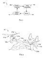
- FIG. 1 depicts a phasing process 101 in accordance with a preferred method of the present application.
- a rotor assembly 103 is operably associated with one or more sensors 105, wherein the sensors are configured to sense vibrations exerted on the aircraft via the two or more rotor assemblies 103.
- the sensed vibrations are relayed to a control system 107 that includes the necessary hardware, software, algorithms and the like to determine the required phasing of the rotor blades of the rotor assemblies relative to each other so as to minimize the vibrations.
- the control system 107 then commands a phase adjustor 109, which in turn adjusts the angle orientation of the rotor blades relative to each other. This process is continuously repeated during flight such that optimal flight conditions are achieved.
- tiltrotor aircraft 201 includes rotor assemblies 213a and 213b that are carried by wings 215a and 215b, and are disposed at end portions 216a and 216b of wings 215a and 215b, respectively.
- Tilt rotor assemblies 213a and 213b include nacelles 220a and 220b, which carry the engines and transmissions of tilt rotor aircraft 201, as well as, rotor proprotors 219a and 219b on forward ends 221 a and 221b of tilt rotor assemblies 213a and 213b, respectively.
- Tilt rotor assemblies 213a and 213b move or rotate relative to wing members 215a and 215b between a helicopter mode in which tilt rotor assemblies 213a and 213b are tilted upward, such that tilt rotor aircraft 201 flies like a conventional helicopter; and an airplane mode in which tilt rotor assemblies 213a and 213b are tilted forward, such that tilt rotor aircraft 201 flies like a conventional propeller driven aircraft.
- the features discussed herein could also be incorporated with any type of aircraft having two or more rotor assemblies that rotate relative to each other and exert vibrations on a fuselage.
- the aircraft could include two rotor assemblies that are not adapted to pivot like a tiltrotor aircraft, but nonetheless include two or more rotor blades that rotate relative to each other, resulting in vibrations on the aircraft.
- FIG. 3 is a top cutout view of a rotor phase angle control system 300 utilized by aircraft 201 and incorporates the features of process 101.
- the rotor phase angle control system 300 is shown operably associated with one or more of the features of aircraft 201.
- FIG. 3 is shown without all the features of aircraft 201.
- system 300 includes the phase adjustor 109 that is driven by the aircraft engine 301 via an input drive shaft 303.
- the phase adjustor 109 is configured to receive the input shaft 303 and transfer the rotational movement thereof to drive the rotor assemblies 213a, 213b via respective output drive shafts 305, 307 the extend through respective wings 215a, 215b of aircraft 201.
- phase adjustor 203 is configured to selectively control the rotational movement of shafts 305, 307.
- phase adjustor 203 is adapted to adjustably offset the rotational movement output shafts 305, 307 relative to each other, which in turn offsets the blade positions of the rotors of the rotor assemblies 213a, 213b relative to each other.
- phase adjustor 203 is a clutch configured to perform these features. Specifically, the clutch is configured to connect and disconnect the output shafts 305, 307 for a predetermined time, thereby allowing the offset of the rotor blades to occur.
- phase adjustor 203 can include other devices substantially similar in function.
- FIGS. 4A and 4B are top views of aircraft 201 that illustrate the foregoing discussed method of phasing the two rotor assemblies relative to each other.
- the longitudinal lengths of the rotor blades 219a, 219b are aligned with each other along axis A, thus the rotor assemblies are considered to be in-phase with each other.
- the control system commands the phase adjustor to offset the rotor blades at a predetermined angle relative to each other, thereby rendering the rotor blades offset from each other and the rotor assemblies out-of-phase with each other.
- the aircraft 201 utilizes the system and methods discussed above.
Landscapes
- Engineering & Computer Science (AREA)
- Aviation & Aerospace Engineering (AREA)
- Mechanical Engineering (AREA)
- Physics & Mathematics (AREA)
- Acoustics & Sound (AREA)
- Wind Motors (AREA)
- Multimedia (AREA)
- General Engineering & Computer Science (AREA)
- Transmission Devices (AREA)
- Vibration Prevention Devices (AREA)
Abstract
Description
- The present application relates generally to systems operably associated with aircraft rotor phasing, and more specifically, to a system configured to provide real-time rotor phasing during flight.
- The process of phasing two or more rotor blade assemblies relative to each other is well known in the art. Phasing is an effective method to control vibrations exerted on the aircraft during flight. Conventional phasing methods include the process of determining optimal offset positions of the rotor blades prior to flight, then retaining the rotor blades in the offset positions during flight. The pre-flight phasing process has shown to be an effective method to control vibrations during flight. Without proper phasing, vibrations on the aircraft create an uncomfortable ride, and in some cases, could cause catastrophic failure to the aircraft.
- Although the foregoing pre-flight phasing methods have shown to be effective, it should be understood that the preset phasing is not ideal for all flight conditions. For example, the aircraft performs differently than the maiden flight and/or the aircraft is required to perform under various flight conditions, e.g., bad weather conditions and/or heavier/lighter payloads. Conventional pre-flight phasing methods are thus limited in view of the foregoing scenarios.
- Although the foregoing developments in the field of phasing multiple rotor blade assemblies relative to each other represent great strides, many shortcomings remain.
- The novel features believed characteristic of the embodiments of the present application are set forth in the appended claims. However, the embodiments themselves, as well as a preferred mode of use, and further objectives and advantages thereof, will best be understood by reference to the following detailed description when read in conjunction with the accompanying drawings, wherein:
-
FIG. 1 is a simplified schematic of a method pursuant to a preferred embodiment of the present application; -
FIG. 2 is a perspective view of a tiltrotor aircraft according to a preferred embodiment of the present application, which utilizes the method ofFIG. 1 ; -
FIG. 3 is a simplified schematic of the phase angle adjustment system associated with the rotor assemblies of the tiltrotor aircraft ofFIG. 2 ; and -
FIGS. 4A and 4B are top views of the tiltrotor aircraft ofFIG. 2 . - While the system and method of the present application is susceptible to various modifications and alternative forms, specific embodiments thereof have been shown by way of example in the drawings and are herein described in detail. It should be understood, however, that the description herein of specific embodiments is not intended to limit the invention to the particular embodiment disclosed, but on the contrary, the intention is to cover all modifications, equivalents, and alternatives falling within the spirit and scope of the process of the present application as defined by the appended claims.
- Illustrative embodiments of the apparatus and method are provided below. It will of course be appreciated that in the development of any actual embodiment, numerous implementation-specific decisions will be made to achieve the developer's specific goals, such as compliance with system-related and business-related constraints, which will vary from one implementation to another. Moreover, it will be appreciated that such a development effort might be complex and time-consuming, but would nevertheless be a routine undertaking for those of ordinary skill in the art having the benefit of this disclosure.
- The system of the present application overcomes the abovementioned problems commonly associated with conventional systems and methods to control vibrations via phasing rotor assemblies. Specifically, the system of the present application includes a phase angle adjustment system having a phase adjustor operably associated with two or more rotor assemblies. The phase adjustor is configured to phase the rotor assemblies relative to each other during flight such that the rotor blades become offset at desired angles relative to each other, thereby eliminating vibrations exerted on the aircraft via the rotor assemblies. The vibrations are continuously monitored via phase angle adjustment system, which in turn allows real-time adjustment of the rotor assemblies during flight. Further detailed description of these features are provided below and illustrated in the accompanying drawings.
- The system and method of the present application will be understood, both as to its structure and operation, from the accompanying drawings, taken in conjunction with the accompanying description. Several embodiments of the system are presented herein. It should be understood that various components, parts, and features of the different embodiments may be combined together and/or interchanged with one another, all of which are within the scope of the present application, even though not all variations and particular embodiments are shown in the drawings. It should also be understood that the mixing and matching of features, elements, and/or functions between various embodiments is expressly contemplated herein so that one of ordinary skill in the art would appreciate from this disclosure that the features, elements, and/or functions of one embodiment may be incorporated into another embodiment as appropriate, unless described otherwise.
- Referring now to the drawings wherein like reference characters identify corresponding or similar elements throughout the several views,
FIG. 1 depicts aphasing process 101 in accordance with a preferred method of the present application. As shown, arotor assembly 103 is operably associated with one ormore sensors 105, wherein the sensors are configured to sense vibrations exerted on the aircraft via the two ormore rotor assemblies 103. The sensed vibrations are relayed to acontrol system 107 that includes the necessary hardware, software, algorithms and the like to determine the required phasing of the rotor blades of the rotor assemblies relative to each other so as to minimize the vibrations. Thecontrol system 107 then commands aphase adjustor 109, which in turn adjusts the angle orientation of the rotor blades relative to each other. This process is continuously repeated during flight such that optimal flight conditions are achieved. These features provide significant advantages, namely, the process allows for real-time monitoring and phase adjustment of the rotor assemblies during flight, thereby enabling vibration control with changes in flight conditions, e.g., changes in weather and/or payload. - Referring now to
FIG. 2 in the drawings, an oblique view of atiltrotor aircraft 201 is shown utilizing thephasing process 101 discussed above. In the exemplary embodiment,tiltrotor aircraft 201 includesrotor assemblies wings end portions wings Tilt rotor assemblies nacelles tilt rotor aircraft 201, as well as,rotor proprotors tilt rotor assemblies wing members tilt rotor aircraft 201 flies like a conventional helicopter; and an airplane mode in which tilt rotor assemblies 213a and 213b are tilted forward, such thattilt rotor aircraft 201 flies like a conventional propeller driven aircraft. - Although shown utilized with a tiltrotor aircraft with rotor blades that rotate on the same plane, it will be appreciated that the features discussed herein could also be incorporated with any type of aircraft having two or more rotor assemblies that rotate relative to each other and exert vibrations on a fuselage. For example, in one contemplated embodiment, the aircraft could include two rotor assemblies that are not adapted to pivot like a tiltrotor aircraft, but nonetheless include two or more rotor blades that rotate relative to each other, resulting in vibrations on the aircraft.
-
FIG. 3 is a top cutout view of a rotor phaseangle control system 300 utilized byaircraft 201 and incorporates the features ofprocess 101. As shown, the rotor phaseangle control system 300 is shown operably associated with one or more of the features ofaircraft 201. For simplicity of illustration,FIG. 3 is shown without all the features ofaircraft 201. In the preferred embodiment,system 300 includes thephase adjustor 109 that is driven by theaircraft engine 301 via aninput drive shaft 303. Thephase adjustor 109 is configured to receive theinput shaft 303 and transfer the rotational movement thereof to drive therotor assemblies output drive shafts respective wings aircraft 201. - In the contemplated embodiment, the phase adjustor 203 is configured to selectively control the rotational movement of
shafts movement output shafts rotor assemblies - In the preferred embodiment, phase adjustor 203 is a clutch configured to perform these features. Specifically, the clutch is configured to connect and disconnect the
output shafts -
FIGS. 4A and 4B are top views ofaircraft 201 that illustrate the foregoing discussed method of phasing the two rotor assemblies relative to each other. InFIG. 4A , the longitudinal lengths of therotor blades FIG. 4B , the control system commands the phase adjustor to offset the rotor blades at a predetermined angle relative to each other, thereby rendering the rotor blades offset from each other and the rotor assemblies out-of-phase with each other. To achieve these features, theaircraft 201 utilizes the system and methods discussed above. - It is apparent that a system and method with significant advantages has been described and illustrated. The particular embodiments disclosed above are illustrative only, as the embodiments may be modified and practiced in different but equivalent manners apparent to those skilled in the art having the benefit of the teachings herein. It is therefore evident that the particular embodiments disclosed above may be altered or modified, and all such variations are considered within the scope and spirit of the application. Accordingly, the protection sought herein is as set forth in the description. Although the present embodiments are shown above, they are not limited to just these embodiments, but are amenable to various changes and modifications without departing from the spirit thereof.
Claims (15)
- An aircraft, comprising:a first rotor assembly and a second rotor assembly; anda rotor phase angle control system having a phase adjustor operably associated with the first rotor assembly and the second rotor assembly;wherein the first rotor assembly rotates relative to the second rotor assembly; andwherein the phase adjustor is configured to adjust the phase angle of the first rotor assembly relative to the second rotor assembly during flight.
- The aircraft of claim 1, the rotor phase angle control system further comprising:a sensor operably associated with the control system; and
a control system operably associated with the sensor;wherein the sensor senses vibrations exerted on the aircraft via the first rotor assembly and the second rotor assembly and relays a sensed vibration to the control system; and
wherein the control system is configured to command the phase adjustor to minimize the vibrations exerted on the aircraft. - The aircraft of claim 1 or claim 2, wherein the phase adjustor is a clutch.
- The aircraft of claim 3, further comprising:a first output shaft rotatably attached to both the clutch and the first rotor assembly; anda second output shaft rotatably attached to both the clutch and the second rotor assembly;
wherein the clutch is configured to disengage and reengage with the first output shaft and the second output shaft so as to offset the first rotor assembly relative to the second rotor assembly. - The aircraft of claim 4, further comprising:an aircraft engine rotatably attached to the clutch via an input shaft;wherein the input shaft rotates that first output shaft and the second output shaft.
- The aircraft of claim 4 or claim 5, wherein the first output shaft extend through a first wing of the aircraft; and
wherein the second output shaft extends through a second wing of the aircraft. - The aircraft of claim 1 or any preceding claim, wherein the aircraft is a tiltrotor aircraft.
- An aircraft rotor phase angle control system, comprising:a phase adjustor operably associated with a first rotor blade and a second rotor blade;wherein the first rotor blade rotates on the same plane as the second rotor blade; andwherein the phase adjustor is configured to offset the phase angle of the first rotor blade relative to the second rotor blade during flight.
- The system of claim 8, further comprising:a sensor associated with the phase adjustor;wherein the sensor senses vibrations exerted by the first rotor and the second rotor.
- The system of claim 9, further comprising:a control system operably associated with the sensor and the phase adjustor;wherein the control system is configured to command the phase adjustor to minimize the vibrations.
- The system of claim 8 or claim 9 or claim 10, wherein the phase adjustor is a clutch.
- The system of claim 11, wherein the clutch is configured to disengage and reengage with a first shaft operably associated with the first rotor and configured to disengage and reengage with a second shaft operably associated with the second rotor.
- A method, comprising:sensing vibrations exerted on a aircraft via two or more rotor assemblies during flight; andoffsetting a phase angle of the two or more rotor assemblies with a phase adjustor to minimize the vibrations;wherein the process of sensing and the process of offsetting are achieved in real-time during flight.
- The method of claim 13, further comprising:relaying the sensed vibration to a control system operably associated with the phase adjustor; and
commanding the phase adjustor via the control system to adjust the phase angle of the two or more rotor assemblies. - The method of claim 13 or claim 14, further comprising:disengaging and reengaging a first shaft operably associated with a first rotor assembly of the two or more rotor assemblies via the phase adjustor;wherein the disengaging and reengaging the first shaft causes the first rotor assembly to offset from a second rotor assembly of the two or more rotor assemblies, thereby creating the phase angle between the two rotor assemblies.
Applications Claiming Priority (1)
| Application Number | Priority Date | Filing Date | Title |
|---|---|---|---|
| US14/174,004 US9889927B2 (en) | 2014-02-06 | 2014-02-06 | Variable hub-to-hub phasing rotor system |
Publications (2)
| Publication Number | Publication Date |
|---|---|
| EP2905223A1 true EP2905223A1 (en) | 2015-08-12 |
| EP2905223B1 EP2905223B1 (en) | 2015-12-30 |
Family
ID=50235988
Family Applications (1)
| Application Number | Title | Priority Date | Filing Date |
|---|---|---|---|
| EP14157931.8A Active EP2905223B1 (en) | 2014-02-06 | 2014-03-05 | Variable hub-to-hub phasing rotor system |
Country Status (2)
| Country | Link |
|---|---|
| US (2) | US9889927B2 (en) |
| EP (1) | EP2905223B1 (en) |
Cited By (1)
| Publication number | Priority date | Publication date | Assignee | Title |
|---|---|---|---|---|
| EP3626628A1 (en) * | 2018-09-18 | 2020-03-25 | Bombardier Inc. | System and method for synchrophasing aircraft engines |
Families Citing this family (11)
| Publication number | Priority date | Publication date | Assignee | Title |
|---|---|---|---|---|
| US10384765B2 (en) | 2014-02-06 | 2019-08-20 | Bell Helicopter Textron Inc. | Interconnect drive system |
| US10408544B2 (en) * | 2014-05-20 | 2019-09-10 | Bell Helicopter Textron Inc. | Composite top case with embedded heat pipes |
| EP3201077B1 (en) | 2014-10-01 | 2020-05-20 | Sikorsky Aircraft Corporation | Dual rotor, rotary wing aircraft |
| US20170267338A1 (en) | 2014-10-01 | 2017-09-21 | Sikorsky Aircraft Corporation | Acoustic signature variation of aircraft utilizing a clutch |
| US10906656B2 (en) | 2018-05-01 | 2021-02-02 | Bell Textron Inc. | Hybrid tiltrotor drive system |
| US11148798B2 (en) * | 2018-06-22 | 2021-10-19 | Textron Innovations Inc. | Engine and rotatable proprotor configurations for a tiltrotor aircraft |
| US10913542B2 (en) * | 2018-07-27 | 2021-02-09 | Textron Innovations Inc. | Conversion actuator and downstop striker fitting for a tiltrotor aircraft |
| US10994839B2 (en) | 2018-07-31 | 2021-05-04 | Textron Innovations Inc. | System and method for rotating a rotor of a tiltrotor aircraft |
| US10773794B2 (en) | 2019-01-10 | 2020-09-15 | Bell Textron Inc. | Dynamic rotor-phasing unit |
| US11781476B2 (en) | 2019-06-25 | 2023-10-10 | Pratt & Whitney Canada Corp. | System and method for operating a multi-engine rotorcraft |
| CN110901906B (en) * | 2019-12-04 | 2023-04-25 | 中国直升机设计研究所 | Ground effect rotor craft and flight mode switching method |
Citations (6)
| Publication number | Priority date | Publication date | Assignee | Title |
|---|---|---|---|---|
| US5148402A (en) * | 1990-12-21 | 1992-09-15 | United Technologies Corporation | Method for reducing aircraft cabin noise and vibration |
| EP0663337A1 (en) * | 1994-01-18 | 1995-07-19 | Fokker Aircraft B.V. | Propeller blade position controller |
| WO1995022488A1 (en) * | 1994-02-18 | 1995-08-24 | United Technologies Corporation | Adaptive synchrophaser for reducing aircraft cabin noise and vibration |
| US5715162A (en) * | 1992-10-13 | 1998-02-03 | United Technologies Corporation | Correlative filter for a synchrophaser |
| EP2132090A1 (en) * | 2007-04-11 | 2009-12-16 | Bell Helicopter Textron Inc. | Method for suppressing vibration and acoustic signature in a tiltrotor aircraft |
| US20100272571A1 (en) * | 2009-04-23 | 2010-10-28 | Yonge Christopher F | Phase adjustment mechanism |
Family Cites Families (1)
| Publication number | Priority date | Publication date | Assignee | Title |
|---|---|---|---|---|
| JPS59220622A (en) * | 1983-05-30 | 1984-12-12 | Nippon Soken Inc | Torque detector |
-
2014
- 2014-02-06 US US14/174,004 patent/US9889927B2/en active Active
- 2014-03-05 EP EP14157931.8A patent/EP2905223B1/en active Active
-
2018
- 2018-02-13 US US15/895,589 patent/US10549849B1/en active Active
Patent Citations (6)
| Publication number | Priority date | Publication date | Assignee | Title |
|---|---|---|---|---|
| US5148402A (en) * | 1990-12-21 | 1992-09-15 | United Technologies Corporation | Method for reducing aircraft cabin noise and vibration |
| US5715162A (en) * | 1992-10-13 | 1998-02-03 | United Technologies Corporation | Correlative filter for a synchrophaser |
| EP0663337A1 (en) * | 1994-01-18 | 1995-07-19 | Fokker Aircraft B.V. | Propeller blade position controller |
| WO1995022488A1 (en) * | 1994-02-18 | 1995-08-24 | United Technologies Corporation | Adaptive synchrophaser for reducing aircraft cabin noise and vibration |
| EP2132090A1 (en) * | 2007-04-11 | 2009-12-16 | Bell Helicopter Textron Inc. | Method for suppressing vibration and acoustic signature in a tiltrotor aircraft |
| US20100272571A1 (en) * | 2009-04-23 | 2010-10-28 | Yonge Christopher F | Phase adjustment mechanism |
Cited By (3)
| Publication number | Priority date | Publication date | Assignee | Title |
|---|---|---|---|---|
| EP3626628A1 (en) * | 2018-09-18 | 2020-03-25 | Bombardier Inc. | System and method for synchrophasing aircraft engines |
| US11686256B2 (en) | 2018-09-18 | 2023-06-27 | Bombardier Inc. | System and method for synchrophasing aircraft engines |
| US12345209B2 (en) | 2018-09-18 | 2025-07-01 | Bombardier Inc. | System and method for synchrophasing aircraft engines |
Also Published As
| Publication number | Publication date |
|---|---|
| US20200023951A1 (en) | 2020-01-23 |
| EP2905223B1 (en) | 2015-12-30 |
| US20150217863A1 (en) | 2015-08-06 |
| US10549849B1 (en) | 2020-02-04 |
| US9889927B2 (en) | 2018-02-13 |
Similar Documents
| Publication | Publication Date | Title |
|---|---|---|
| US10549849B1 (en) | Variable hub-to-hub phasing rotor system | |
| US10384765B2 (en) | Interconnect drive system | |
| US9964960B2 (en) | Hover attitude trim for vehicle | |
| CA2844214C (en) | Hybrid fluid elastomeric damper | |
| US10106251B2 (en) | Variable anhedral tip rotor blade | |
| EP2947007A1 (en) | Adjustable blade-to-hub lead-lag damper attachment | |
| US9656747B2 (en) | Soft in-plane and stiff out-of-plane rotor system | |
| US20180093764A1 (en) | Articulated Main Rotor Hub with Inwardly CF Bearing and 3% Flapping Hinge Offset | |
| US10759530B2 (en) | Vibration control with active lag damper | |
| US10106255B2 (en) | Rotary pylon conversion actuator for tiltrotor aircraft | |
| US9828088B2 (en) | Scissoring fold arrangement for dual plane four bladed rotor hubs | |
| EP2722277B1 (en) | Direct-drive control of aircraft stability augmentation | |
| US20170225774A1 (en) | Anti-vibration load generating aircraft actuation system | |
| EP3395680A1 (en) | Interconnect drive system | |
| EP3737609A1 (en) | Transmission system for aircraft structure | |
| US9353820B2 (en) | Elastomeric damper with heater | |
| US10611472B2 (en) | Coaxial rotor yaw control | |
| US10577089B2 (en) | Integrated bifilar system that absorbs vibrations in both vertical and in-plane directions |
Legal Events
| Date | Code | Title | Description |
|---|---|---|---|
| PUAI | Public reference made under article 153(3) epc to a published international application that has entered the european phase |
Free format text: ORIGINAL CODE: 0009012 |
|
| 17P | Request for examination filed |
Effective date: 20140305 |
|
| AK | Designated contracting states |
Kind code of ref document: A1 Designated state(s): AL AT BE BG CH CY CZ DE DK EE ES FI FR GB GR HR HU IE IS IT LI LT LU LV MC MK MT NL NO PL PT RO RS SE SI SK SM TR |
|
| AX | Request for extension of the european patent |
Extension state: BA ME |
|
| GRAP | Despatch of communication of intention to grant a patent |
Free format text: ORIGINAL CODE: EPIDOSNIGR1 |
|
| RIC1 | Information provided on ipc code assigned before grant |
Ipc: B64C 27/30 20060101ALI20150911BHEP Ipc: B64C 27/00 20060101ALI20150911BHEP Ipc: B64C 11/50 20060101AFI20150911BHEP |
|
| GRAS | Grant fee paid |
Free format text: ORIGINAL CODE: EPIDOSNIGR3 |
|
| INTG | Intention to grant announced |
Effective date: 20151013 |
|
| GRAA | (expected) grant |
Free format text: ORIGINAL CODE: 0009210 |
|
| AK | Designated contracting states |
Kind code of ref document: B1 Designated state(s): AL AT BE BG CH CY CZ DE DK EE ES FI FR GB GR HR HU IE IS IT LI LT LU LV MC MK MT NL NO PL PT RO RS SE SI SK SM TR |
|
| REG | Reference to a national code |
Ref country code: GB Ref legal event code: FG4D |
|
| REG | Reference to a national code |
Ref country code: CH Ref legal event code: EP |
|
| REG | Reference to a national code |
Ref country code: AT Ref legal event code: REF Ref document number: 767322 Country of ref document: AT Kind code of ref document: T Effective date: 20160115 |
|
| REG | Reference to a national code |
Ref country code: IE Ref legal event code: FG4D |
|
| REG | Reference to a national code |
Ref country code: DE Ref legal event code: R096 Ref document number: 602014000631 Country of ref document: DE |
|
| REG | Reference to a national code |
Ref country code: FR Ref legal event code: PLFP Year of fee payment: 3 |
|
| REG | Reference to a national code |
Ref country code: LT Ref legal event code: MG4D |
|
| PG25 | Lapsed in a contracting state [announced via postgrant information from national office to epo] |
Ref country code: HR Free format text: LAPSE BECAUSE OF FAILURE TO SUBMIT A TRANSLATION OF THE DESCRIPTION OR TO PAY THE FEE WITHIN THE PRESCRIBED TIME-LIMIT Effective date: 20151230 Ref country code: NO Free format text: LAPSE BECAUSE OF FAILURE TO SUBMIT A TRANSLATION OF THE DESCRIPTION OR TO PAY THE FEE WITHIN THE PRESCRIBED TIME-LIMIT Effective date: 20160330 Ref country code: LT Free format text: LAPSE BECAUSE OF FAILURE TO SUBMIT A TRANSLATION OF THE DESCRIPTION OR TO PAY THE FEE WITHIN THE PRESCRIBED TIME-LIMIT Effective date: 20151230 |
|
| REG | Reference to a national code |
Ref country code: NL Ref legal event code: MP Effective date: 20151230 |
|
| REG | Reference to a national code |
Ref country code: AT Ref legal event code: MK05 Ref document number: 767322 Country of ref document: AT Kind code of ref document: T Effective date: 20151230 |
|
| PG25 | Lapsed in a contracting state [announced via postgrant information from national office to epo] |
Ref country code: RS Free format text: LAPSE BECAUSE OF FAILURE TO SUBMIT A TRANSLATION OF THE DESCRIPTION OR TO PAY THE FEE WITHIN THE PRESCRIBED TIME-LIMIT Effective date: 20151230 Ref country code: LV Free format text: LAPSE BECAUSE OF FAILURE TO SUBMIT A TRANSLATION OF THE DESCRIPTION OR TO PAY THE FEE WITHIN THE PRESCRIBED TIME-LIMIT Effective date: 20151230 Ref country code: SE Free format text: LAPSE BECAUSE OF FAILURE TO SUBMIT A TRANSLATION OF THE DESCRIPTION OR TO PAY THE FEE WITHIN THE PRESCRIBED TIME-LIMIT Effective date: 20151230 Ref country code: FI Free format text: LAPSE BECAUSE OF FAILURE TO SUBMIT A TRANSLATION OF THE DESCRIPTION OR TO PAY THE FEE WITHIN THE PRESCRIBED TIME-LIMIT Effective date: 20151230 Ref country code: GR Free format text: LAPSE BECAUSE OF FAILURE TO SUBMIT A TRANSLATION OF THE DESCRIPTION OR TO PAY THE FEE WITHIN THE PRESCRIBED TIME-LIMIT Effective date: 20160331 |
|
| PG25 | Lapsed in a contracting state [announced via postgrant information from national office to epo] |
Ref country code: NL Free format text: LAPSE BECAUSE OF FAILURE TO SUBMIT A TRANSLATION OF THE DESCRIPTION OR TO PAY THE FEE WITHIN THE PRESCRIBED TIME-LIMIT Effective date: 20151230 |
|
| PG25 | Lapsed in a contracting state [announced via postgrant information from national office to epo] |
Ref country code: ES Free format text: LAPSE BECAUSE OF FAILURE TO SUBMIT A TRANSLATION OF THE DESCRIPTION OR TO PAY THE FEE WITHIN THE PRESCRIBED TIME-LIMIT Effective date: 20151230 Ref country code: CZ Free format text: LAPSE BECAUSE OF FAILURE TO SUBMIT A TRANSLATION OF THE DESCRIPTION OR TO PAY THE FEE WITHIN THE PRESCRIBED TIME-LIMIT Effective date: 20151230 |
|
| PG25 | Lapsed in a contracting state [announced via postgrant information from national office to epo] |
Ref country code: BE Free format text: LAPSE BECAUSE OF NON-PAYMENT OF DUE FEES Effective date: 20160331 Ref country code: PL Free format text: LAPSE BECAUSE OF FAILURE TO SUBMIT A TRANSLATION OF THE DESCRIPTION OR TO PAY THE FEE WITHIN THE PRESCRIBED TIME-LIMIT Effective date: 20151230 Ref country code: RO Free format text: LAPSE BECAUSE OF FAILURE TO SUBMIT A TRANSLATION OF THE DESCRIPTION OR TO PAY THE FEE WITHIN THE PRESCRIBED TIME-LIMIT Effective date: 20151230 Ref country code: SM Free format text: LAPSE BECAUSE OF FAILURE TO SUBMIT A TRANSLATION OF THE DESCRIPTION OR TO PAY THE FEE WITHIN THE PRESCRIBED TIME-LIMIT Effective date: 20151230 Ref country code: AT Free format text: LAPSE BECAUSE OF FAILURE TO SUBMIT A TRANSLATION OF THE DESCRIPTION OR TO PAY THE FEE WITHIN THE PRESCRIBED TIME-LIMIT Effective date: 20151230 Ref country code: IS Free format text: LAPSE BECAUSE OF FAILURE TO SUBMIT A TRANSLATION OF THE DESCRIPTION OR TO PAY THE FEE WITHIN THE PRESCRIBED TIME-LIMIT Effective date: 20160430 Ref country code: PT Free format text: LAPSE BECAUSE OF FAILURE TO SUBMIT A TRANSLATION OF THE DESCRIPTION OR TO PAY THE FEE WITHIN THE PRESCRIBED TIME-LIMIT Effective date: 20160502 Ref country code: EE Free format text: LAPSE BECAUSE OF FAILURE TO SUBMIT A TRANSLATION OF THE DESCRIPTION OR TO PAY THE FEE WITHIN THE PRESCRIBED TIME-LIMIT Effective date: 20151230 Ref country code: SK Free format text: LAPSE BECAUSE OF FAILURE TO SUBMIT A TRANSLATION OF THE DESCRIPTION OR TO PAY THE FEE WITHIN THE PRESCRIBED TIME-LIMIT Effective date: 20151230 |
|
| REG | Reference to a national code |
Ref country code: DE Ref legal event code: R097 Ref document number: 602014000631 Country of ref document: DE |
|
| PG25 | Lapsed in a contracting state [announced via postgrant information from national office to epo] |
Ref country code: DK Free format text: LAPSE BECAUSE OF FAILURE TO SUBMIT A TRANSLATION OF THE DESCRIPTION OR TO PAY THE FEE WITHIN THE PRESCRIBED TIME-LIMIT Effective date: 20151230 Ref country code: LU Free format text: LAPSE BECAUSE OF FAILURE TO SUBMIT A TRANSLATION OF THE DESCRIPTION OR TO PAY THE FEE WITHIN THE PRESCRIBED TIME-LIMIT Effective date: 20160305 Ref country code: MC Free format text: LAPSE BECAUSE OF FAILURE TO SUBMIT A TRANSLATION OF THE DESCRIPTION OR TO PAY THE FEE WITHIN THE PRESCRIBED TIME-LIMIT Effective date: 20151230 |
|
| PLBE | No opposition filed within time limit |
Free format text: ORIGINAL CODE: 0009261 |
|
| STAA | Information on the status of an ep patent application or granted ep patent |
Free format text: STATUS: NO OPPOSITION FILED WITHIN TIME LIMIT |
|
| 26N | No opposition filed |
Effective date: 20161003 |
|
| REG | Reference to a national code |
Ref country code: IE Ref legal event code: MM4A |
|
| PG25 | Lapsed in a contracting state [announced via postgrant information from national office to epo] |
Ref country code: BE Free format text: LAPSE BECAUSE OF FAILURE TO SUBMIT A TRANSLATION OF THE DESCRIPTION OR TO PAY THE FEE WITHIN THE PRESCRIBED TIME-LIMIT Effective date: 20151230 |
|
| PG25 | Lapsed in a contracting state [announced via postgrant information from national office to epo] |
Ref country code: IE Free format text: LAPSE BECAUSE OF NON-PAYMENT OF DUE FEES Effective date: 20160305 |
|
| PG25 | Lapsed in a contracting state [announced via postgrant information from national office to epo] |
Ref country code: SI Free format text: LAPSE BECAUSE OF FAILURE TO SUBMIT A TRANSLATION OF THE DESCRIPTION OR TO PAY THE FEE WITHIN THE PRESCRIBED TIME-LIMIT Effective date: 20151230 |
|
| REG | Reference to a national code |
Ref country code: FR Ref legal event code: PLFP Year of fee payment: 4 |
|
| PG25 | Lapsed in a contracting state [announced via postgrant information from national office to epo] |
Ref country code: MT Free format text: LAPSE BECAUSE OF FAILURE TO SUBMIT A TRANSLATION OF THE DESCRIPTION OR TO PAY THE FEE WITHIN THE PRESCRIBED TIME-LIMIT Effective date: 20151230 |
|
| REG | Reference to a national code |
Ref country code: CH Ref legal event code: PL |
|
| PG25 | Lapsed in a contracting state [announced via postgrant information from national office to epo] |
Ref country code: LI Free format text: LAPSE BECAUSE OF NON-PAYMENT OF DUE FEES Effective date: 20170331 Ref country code: CH Free format text: LAPSE BECAUSE OF NON-PAYMENT OF DUE FEES Effective date: 20170331 |
|
| REG | Reference to a national code |
Ref country code: FR Ref legal event code: PLFP Year of fee payment: 5 |
|
| PG25 | Lapsed in a contracting state [announced via postgrant information from national office to epo] |
Ref country code: HU Free format text: LAPSE BECAUSE OF FAILURE TO SUBMIT A TRANSLATION OF THE DESCRIPTION OR TO PAY THE FEE WITHIN THE PRESCRIBED TIME-LIMIT; INVALID AB INITIO Effective date: 20140305 |
|
| PG25 | Lapsed in a contracting state [announced via postgrant information from national office to epo] |
Ref country code: MK Free format text: LAPSE BECAUSE OF FAILURE TO SUBMIT A TRANSLATION OF THE DESCRIPTION OR TO PAY THE FEE WITHIN THE PRESCRIBED TIME-LIMIT Effective date: 20151230 Ref country code: MT Free format text: LAPSE BECAUSE OF FAILURE TO SUBMIT A TRANSLATION OF THE DESCRIPTION OR TO PAY THE FEE WITHIN THE PRESCRIBED TIME-LIMIT Effective date: 20160331 Ref country code: CY Free format text: LAPSE BECAUSE OF FAILURE TO SUBMIT A TRANSLATION OF THE DESCRIPTION OR TO PAY THE FEE WITHIN THE PRESCRIBED TIME-LIMIT Effective date: 20151230 |
|
| PG25 | Lapsed in a contracting state [announced via postgrant information from national office to epo] |
Ref country code: BG Free format text: LAPSE BECAUSE OF FAILURE TO SUBMIT A TRANSLATION OF THE DESCRIPTION OR TO PAY THE FEE WITHIN THE PRESCRIBED TIME-LIMIT Effective date: 20151230 |
|
| PG25 | Lapsed in a contracting state [announced via postgrant information from national office to epo] |
Ref country code: AL Free format text: LAPSE BECAUSE OF FAILURE TO SUBMIT A TRANSLATION OF THE DESCRIPTION OR TO PAY THE FEE WITHIN THE PRESCRIBED TIME-LIMIT Effective date: 20151230 Ref country code: TR Free format text: LAPSE BECAUSE OF FAILURE TO SUBMIT A TRANSLATION OF THE DESCRIPTION OR TO PAY THE FEE WITHIN THE PRESCRIBED TIME-LIMIT Effective date: 20151230 |
|
| P01 | Opt-out of the competence of the unified patent court (upc) registered |
Effective date: 20230602 |
|
| PGFP | Annual fee paid to national office [announced via postgrant information from national office to epo] |
Ref country code: GB Payment date: 20260327 Year of fee payment: 13 |
|
| PGFP | Annual fee paid to national office [announced via postgrant information from national office to epo] |
Ref country code: DE Payment date: 20260327 Year of fee payment: 13 |
|
| PGFP | Annual fee paid to national office [announced via postgrant information from national office to epo] |
Ref country code: IT Payment date: 20260319 Year of fee payment: 13 |
|
| PGFP | Annual fee paid to national office [announced via postgrant information from national office to epo] |
Ref country code: FR Payment date: 20260325 Year of fee payment: 13 |