EP2905190A1 - Feststellbremsvorrichtung einer pneumatischen Bremsanlage - Google Patents
Feststellbremsvorrichtung einer pneumatischen Bremsanlage Download PDFInfo
- Publication number
- EP2905190A1 EP2905190A1 EP15000121.2A EP15000121A EP2905190A1 EP 2905190 A1 EP2905190 A1 EP 2905190A1 EP 15000121 A EP15000121 A EP 15000121A EP 2905190 A1 EP2905190 A1 EP 2905190A1
- Authority
- EP
- European Patent Office
- Prior art keywords
- brake
- valve
- parking brake
- pressure port
- towing vehicle
- Prior art date
- Legal status (The legal status is an assumption and is not a legal conclusion. Google has not performed a legal analysis and makes no representation as to the accuracy of the status listed.)
- Granted
Links
Images


Classifications
-
- B—PERFORMING OPERATIONS; TRANSPORTING
- B60—VEHICLES IN GENERAL
- B60T—VEHICLE BRAKE CONTROL SYSTEMS OR PARTS THEREOF; BRAKE CONTROL SYSTEMS OR PARTS THEREOF, IN GENERAL; ARRANGEMENT OF BRAKING ELEMENTS ON VEHICLES IN GENERAL; PORTABLE DEVICES FOR PREVENTING UNWANTED MOVEMENT OF VEHICLES; VEHICLE MODIFICATIONS TO FACILITATE COOLING OF BRAKES
- B60T13/00—Transmitting braking action from initiating means to ultimate brake actuator with power assistance or drive; Brake systems incorporating such transmitting means, e.g. air-pressure brake systems
- B60T13/10—Transmitting braking action from initiating means to ultimate brake actuator with power assistance or drive; Brake systems incorporating such transmitting means, e.g. air-pressure brake systems with fluid assistance, drive, or release
- B60T13/66—Electrical control in fluid-pressure brake systems
- B60T13/68—Electrical control in fluid-pressure brake systems by electrically-controlled valves
- B60T13/683—Electrical control in fluid-pressure brake systems by electrically-controlled valves in pneumatic systems or parts thereof
-
- B—PERFORMING OPERATIONS; TRANSPORTING
- B60—VEHICLES IN GENERAL
- B60T—VEHICLE BRAKE CONTROL SYSTEMS OR PARTS THEREOF; BRAKE CONTROL SYSTEMS OR PARTS THEREOF, IN GENERAL; ARRANGEMENT OF BRAKING ELEMENTS ON VEHICLES IN GENERAL; PORTABLE DEVICES FOR PREVENTING UNWANTED MOVEMENT OF VEHICLES; VEHICLE MODIFICATIONS TO FACILITATE COOLING OF BRAKES
- B60T15/00—Construction arrangement, or operation of valves incorporated in power brake systems and not covered by groups B60T11/00 or B60T13/00
- B60T15/02—Application and release valves
- B60T15/04—Driver's valves
- B60T15/041—Driver's valves controlling auxiliary pressure brakes, e.g. parking or emergency brakes
Definitions
- the invention relates to a parking brake device of a pneumatic brake system of a tractor designed as a towing vehicle with the features of the preamble of claim 1.
- WABCO publication entitled "Training documents, basic course part 4", page 2 are known, in addition to the usual in compressed air brake systems in commercial vehicles components, such as reservoir, compressors, air dryers, foot brake valves, etc. also a parking brake device, which conventionally constructed air brake systems a parking brake operating device designed as a parking brake device. If the commercial vehicle has assumed a desired parking position, the driver of the utility vehicle actuates the parking brake device, whereby at least the parking brake cylinders of an axle are vented, which causes the brakes of at least one axle to be permanently fixed.
- Conventional brake systems also have a towing vehicle arranged on the trailer control valve, through which compressed air is also supplied to the towing vehicle coupling heads "brake" and "supply" is supplied.
- the towing vehicle compressed air reaches the towing vehicle coupled to the trailer, which has its own brake system.
- the injected into the trailer vehicle compressed air causes a braking of the trailer vehicle according to the braking request of the driver of the towing vehicle.
- an actuation of the parking brake device not only causes a brake application of the parking brake of the towing vehicle, but also via appropriate control and brake lines of the trailer control valve, a brake application of the trailer vehicle, as normally when reaching a parking position, not only the towing vehicle, but also the trailer vehicle permanently braked.
- a release valve is usually arranged on the trailer, by which the parking brake can be manually released. This release valve arranged on the trailer vehicle has been marketed by WABCO under the part number 963 006 001 0 for years and is described in a WABCO publication, which is available on the Internet at the following link:
- APM Air Processing Module
- Such APM are for example from the DE 10 2004 051 309 A1 , of the DE 10 2005 026 343 A1 , of the DE 10 2006 055 570 A1 , of the DE 10 2006 055 569 A1 , of the EP 1 731 393 B1 , of the EP 1 731 394 B1 and the EP 1 731 395 B1 known.
- no mechanical-pneumatic parking brake device is present; the driver initializes the parking brakes of at least the towing vehicle by operating an electrical switch.
- the invention is based on the surprising finding that the object can be achieved by arranging a valve device between the line leading from the trailer control valve to the "brake” coupling head, through which the compressed air line leading to the "brake” coupling head is connected to the coupling head " Stock "leading line can be connected.
- This valve device is arranged on the towing vehicle so that the driver entrusted with the loading and unloading can be conveniently supplied with compressed air to the trailer vehicle and thereby compressed air to the parking brakes of the trailer vehicle.
- the invention is characterized in that between the towing vehicle arranged trailer control valve and arranged on the towing vehicle coupling heads arranged on the towing vehicle valve means is arranged, through which a pneumatic connection of the brake coupling head is connectable either to a brake pressure port of the trailer control valve or to a supply pressure port of the trailer control valve and the supply coupling head.
- a particularly simple and economically favorable solution results from the fact that as a valve device such is used, which has hitherto been used exclusively for trailer vehicles as a release valve. While the release valve was otherwise used to release the brake of the trailer vehicle, it is now used in reverse action, that is, by the release valve now serving as a release valve, the parking brake of the trailer vehicle is operated.
- An advantage of using a known release valve which, for example, from WABCO under the part no. 963 006 001 0 or from the company Knorr-Bremse Systems for commercial vehicles under the part no.
- AE4261 also results from the fact that the valve is designed so that the first time the brake is applied after restart of the towing vehicle automatically a lower pressure of about 2.5 bar is applied to the connecting line of the release valve, whereby the actuating piston of the release valve automatically gets into its initial position, causing a release of the brake of the trailer vehicle.
- This allows a particularly ergonomic mode of operation of the commercial vehicle, because the driver only has to actuate the valve device for inserting the brake of the trailer vehicle, but this does not bring by separate handles back to its starting position, as the system takes over this virtually automatically, which excludes incorrect conditions.
- valve device is designed as a 2/3-way valve, wherein in a lower position of the valve device is a connection of the brake pressure port of the trailer control valve via an input port of the valve device with the brake pressure port of the brake coupling head and wherein in an upper position of the valve means there is a connection of the reservoir pressure port of the trailer control valve and the reservoir pressure port of the supply coupling head to the brake pressure port of the brake coupling head.
- the valve device is designed as a 3/3-way valve, wherein in a lower position of the valve device, a connection of the brake pressure port of the trailer control valve via an input port of the valve device with the brake pressure port of the brake coupling head, and wherein in an upper position the valve means comprises a connection of the reservoir pressure port of the trailer control valve and the reservoir pressure port of the supply coupling head with the brake pressure port of the brake coupling head, and wherein in a middle position between the lower position and the upper position of the valve means, both the brake pressure port of the brake coupling head, and the Supply pressure port of the supply coupling head are shut off.
- valve device has a housing, along the longitudinal axis of which a valve piston is displaceably arranged, which is connected to an actuating knob.
- valve device is fastened with its actuating knob by means of a mounting flange on the outside of the frame of the towing vehicle.
- the parking brake device has a parking brake operating device designed as a hand brake valve, which is connected via a check valve to a compressed air reservoir.
- the parking brake device has an air processing module with an electronically controlled air treatment unit, wherein an electronically controlled parking brake module is flanged to the air treatment unit.
- trailer control valve is designed as a trailer brake module, to which the valve device can be flanged in a modular design.
- valve device is arranged in the cab of the towing vehicle.
- valve device is designed as a solenoid valve.
- the components of the parking brake device according to the invention are provided with normal reference numerals, while the pneumatic connections or lines are marked according to DIN / ISO 6786, in deviation to DIN / ISO 8786 but each with an "L” as a prefix for better demarcation the reference numerals are indicated.
- the connection "L21" thus corresponds to the connection 21 of DIN / ISO 6786.
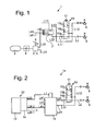
- Fig. 1 1 shows a first exemplary embodiment of a parking brake device 1 of a pneumatic brake system of a commercial vehicle designed as a towing vehicle, with only the essential components of the parking brake device being illustrated, while the other usual components of a pneumatic brake system in Fig. 1 not shown.
- the parking brake device 1 has a parking brake operating device 2, which is designed as a hand brake valve 3, is connected via a check valve 4 to a compressed air reservoir 5.
- a line L21 leads to a parking brake device, not shown, of the towing vehicle.
- a lever 6 of the hand brake valve 3 If a lever 6 of the hand brake valve 3 is actuated, compressed air from the compressed air reservoir passes via the connection L21 to the parking brake of the towing vehicle and via a brake pressure connection L22 to a brake pressure or control pressure port L43 of a trailer control valve 7, shown only schematically, known per se.
- the trailer control valve 7 has more Control terminals L11, L42 and L41 on, but it does not matter below.
- a supply pressure is looped through the supply pressure port L12 to a supply coupling head 8; the coupling head "supply” 8 is connected in the coupled vehicle of a trailer vehicle with a corresponding control line of the trailer vehicle and supplies supply pressure of the brake system of the trailer vehicle.
- An actuated brake pressure leaves the trailer control valve 7 via the brake pressure connection L22 and arrives at a coupling head "brake” or a brake coupling head 9.
- actuation of the parking brake actuator 2 would also cause a brake pressure across the brake Coupling head 9 would be controlled by the corresponding brake line of the trailer vehicle, whereby the brake of the trailer vehicle would be actuated.
- the controlled brake pressure is not controlled through to the brake of the trailer, so that the brake of the trailer remains unconfirmed.
- a valve device 10 is disposed between the brake pressure port L22 on the trailer control valve 7 and the brake pressure port L2 of the brake coupling head 9. This valve device 10 is arranged on the towing vehicle, which is based on Fig. 5 will be explained in more detail.
- the valve device 10 whose structural design in connection with Fig. 3 will be explained in more detail, is designed as a 3/3-way valve and has an actuating knob 11. In the normal state of a lower position 10a, which in Fig. 1 is shown, there is a connection from the brake pressure port L22 to the brake pressure port L2 of the brake coupling head 9, so that the brake cylinder of the parking brake system of the trailer vehicle ventilated and its brake is thus ineffective.
- the valve When the button 11 is depressed, the valve is shifted from the lower position 10a via a middle position 10b to an upper position 10c, whereby the terminals L22 of the trailer brake valve 7 and the port L2 of the brake coupling head 9 separated and instead the supply terminal L12 with the terminal L2 of the brake coupling head 9 are connected, whereby the brakes of the trailer vehicle are activated.
- the driver then starts after successful loading and unloading the towing vehicle and activates the brake system of the vehicle for the first time, passes a minimum pressure of about 2.5 bar via the input terminal L11 in the valve device 10, which causes the valve piston of the valve device 10 is pushed up and the terminal L22 is reconnected to the terminal L2 of the brake coupling head 9, which in turn results in that the braking device of the trailer vehicle is released.
- a second embodiment of a parking brake device 1 a is shown, in which the same reference numerals and terminal identifiers are used for the same parts.
- the parking brake device 1 a according to Fig. 2 differs from the parking brake device 1 according to Fig. 1 in that no mechanical-pneumatic parking brake device is present here.
- a so-called "Air Processing Module 12" or APM 12 is present in the parking brake device 1 a according to Fig. 2 Instead, a so-called "Air Processing Module 12" or APM 12 is present.
- This consists of an electronically controlled air treatment unit 13, which electronically controlled by a compressor connected to the engine of the towing vehicle compressor cleans and a in Fig. 2 not shown supply reservoir.
- an electronically controlled parking brake module 14 is flanged.
- a trailer brake module 15 This is activated by an in-cab switch for activating the parking brake.
- air pressure via a port L28.1 to parking brakes, not shown the towing vehicle and via terminals L28.2 and L23 to terminals L1 and L43 of a trailer brake module 15 indicated only schematically.
- This takes over the function of the trailer control valve 7 Fig. 1 and can be constructed like this.
- the trailer brake module 15 fulfills further functions and is provided with independent control logic, wherein it is also possible to hook the trailer brake module 15 to the air conditioning unit 13 or to the parking brake module 14, so that in this case a structural unit of air conditioning unit 13, parking brake module 14 and trailer brake module 15 results.
- the other components of the parking brake device 1a according to Fig. 2 correspond to those from Fig. 1 What applies in particular with regard to the valve device 10.
- the valve device 10 in deviation from the illustration according to the Fig. 1 and 2 be designed as a 2/3-way valve.
- the middle position 10b would be omitted, in which all three ports L11, L12, L2 are separated from each other.
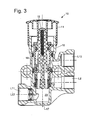
- Fig. 3 is the valve device 10 of Figures 1 and 2 shown in longitudinal section.
- the valve device 10 corresponds in construction terms to a release valve known valve, which is sold by the company WABCO under the part number 963 006 001 0.
- the valve device 10 according to the invention but not as a release valve, but as a check valve, since after pressing, that is, depression, the operating knob 11, first, the terminals L11, L22 and L2 are separated from each other - which the middle position 10b of Fig. 1 and 2 corresponds to - then, ie when reaching the upper position 10c, the terminals L2 and L12 are connected to each other, resulting in the actuation of the braking device of the trailer vehicle.
- the valve device 10 has a housing 16, along the longitudinal axis 17, a valve piston 18 is slidably disposed.
- the valve piston 18 is connected by means of a screw 19 with the actuating knob 11.
- the valve piston 18 is in its maximum extended, that is axially upper position, which is the lower position 10a of Fig. 1 and 2 equivalent.
- the device port L11 or L22 is connected to the brake pressure port L2.
- the brake pressure port L2 is connected to the supply port L12. This causes the brake of the trailer vehicle is activated. The trailer is then braked.
- an "X" means the minimum pressure that is necessary to bring the valve piston 18 of the valve device in its release position, ie upwards. As a rule, this minimum value is approx. 2.5 bar.
- a commercial vehicle 21 is shown from the side.
- the commercial vehicle 21 consists of a combination of a towing vehicle 22 and a trailer vehicle 23, wherein the trailer vehicle 23 is shown only very schematically.
- the trailer vehicle 23 is mechanically coupled to the tractor 22 in a suitable manner, not shown.
- the trailer vehicle 23 may also be a semi-trailer, which rests on a frame 24 of the towing vehicle.
- the parking brake device 1a from Fig. 2 attached to the frame 24 of the towing vehicle.
- the air processing module 12 which has an air treatment unit 13 with attached filter cartridge 25.
- the parking brake module 14 is flanged to the air treatment unit 13.
- the parking brake module 14 is connected to the trailer brake module 15 via lines L23 and L28.2.
- the terminal L22 of the trailer brake module 15 is pneumatically connected via a connecting line 27 with the in Fig. 5 not shown input terminal L11 of the valve device 10 connected.
- the valve device 10 is in turn connected via a connecting line not shown with a brake line 28 to the brake pressure port L2 of the brake coupling head 9, which in turn is connected via a brake line 29 to the brake system of the trailer vehicle 23, not shown.
- the valve device 10 is connected via a connecting line, not shown, with a supply line 30 to the supply terminal L12 of the supply coupling head 8, which is connected via a supply line 31 with the brake system of the trailer vehicle 23, not shown.
- valve device 10 is screwed quasi-lying with its operating knob 11 via a mounting flange 32 on the frame 24 of the towing vehicle 22.
- the installation position shown on towing vehicle 22 allows the driver to conveniently press the actuating head 11 before loading and unloading, whereby the parking brake of the trailer vehicle 23 is actuated.
- valve device 10 at another point of the towing vehicle, for example, it is possible to flangle the valve device 10 in a modular design on the trailer braking module 15. Also conceivable is an attachment of the valve device in the cab 33rd However, for safety reasons, an attachment outside of the towing vehicle 22 will be preferred.
- valve device 10 could be electrically operated, for example by simply pressing a on or in the towing vehicle 22 arranged pushbutton.
- the motorized actuator can be wired or wireless.
- the remote control can be designed as a special software program or "app" of a smartphone.
- remote control could be further functions of the commercial vehicle 21 control during loading and unloading, such as lifting and lowering the trailer vehicle, the lifting and lowering a towing axle, and the like.
- valve device 10 it is also possible to design the valve device 10 as a solenoid valve. In this case, the control of the valve device would be purely electrical or electronic. In this case too, it would be possible to switch the valve device 10 embodied as a solenoid valve by means of a remote control, which may be designed as shown above.
Landscapes
- Engineering & Computer Science (AREA)
- Transportation (AREA)
- Mechanical Engineering (AREA)
- Regulating Braking Force (AREA)
- Valves And Accessory Devices For Braking Systems (AREA)
- Braking Systems And Boosters (AREA)
Abstract
Description
- Die Erfindung betrifft eine Feststellbremsvorrichtung einer pneumatischen Bremsanlage eines als Zugfahrzeug ausgebildeten Nutzfahrzeugs mit den Merkmalen des Oberbegriffs des Patentanspruchs 1.
- Übliche Bremsanlagen von Nutzfahrzeugen, wie sie beispielsweise aus der im Internet unter dem Link
- http://inform.wabco-auto.com/intl/scrints/download.php?from=/intl/de/informpm.php&lang=&keywords=&file=../../i ntl/pdf/815/00/57/8150200573-04.pdf
- abrufbaren WABCO-Druckschrift "Trainings-Unterlagen, Grundlehrgang Teil 4", Seite 2, bekannt sind, weisen neben den bei Druckluftbremsanlagen bei Nutzfahrzeugen üblichen Komponenten, wie Vorratsbehälter, Kompressoren, Lufttrocknern, Fußbremsventilen usw. auch eine Feststellbremsvorrichtung auf, welche bei konventionell aufgebauten Druckluftbremsanlagen eine als Feststellbremsvorrichtung ausgebildete Feststellbremsbetätigungseinrichtung aufweist. Hat das Nutzfahrzeug eine gewünschte Parkposition eingenommen, betätigt der Fahrer des Nutzfahrzeugs das Feststellbremsvorrichtung, wodurch wenigstens die Feststellbremszylinder einer Achse entlüftet werden, was bewirkt, dass die Bremsen wenigstens einer Achse dauerhaft festgelegt werden. Übliche Bremsanlagen weisen auch ein am Zugfahrzeug angeordnetes Anhängersteuerventil auf, durch welches Druckluft den ebenfalls am Zugfahrzeug angeordneten Kupplungsköpfen "Bremse" und "Vorrat" zugeführt wird. Über die Kupplungsköpfe des Zugfahrzeugs gelangt Druckluft zum am Zugfahrzeug angekoppelten Anhängerfahrzeug, welches über eine eigene Bremsanlage verfügt. Die in das Anhängerfahrzeug eingespeiste Druckluft bewirkt eine Bremsung des Anhängerfahrzeuges entsprechend dem Bremswunsch des Fahrers des Zugfahrzeuges.
- In der Regel bewirkt eine Betätigung des Feststellbremsvorrichtung nicht nur eine Zuspannung der Feststellbremsen des Zugfahrzeugs, sondern auch über entsprechende Steuer- und Bremsleitungen des Anhängersteuerventils eine Zuspannung der Bremsen des Anhängerfahrzeuges, da im Normalfall bei Erreichen einer Parkposition nicht nur das Zugfahrzeug, sondern auch das Anhängerfahrzeug dauerhaft gebremst bleibt. Um nach Abkoppeln des Anhängerfahrzeugs vom Zugfahrzeug, beispielsweise beim Be- und Entladen des Anhängerfahrzeuges, dieses Anhängerfahrzeug rangieren zu können, ist in der Regel am Anhängerfahrzeug ein Löseventil angeordnet, durch welches manuell die Parkbremse gelöst werden kann. Dieses am Anhängerfahrzeug angeordnete Löseventil wird von der Firma WABCO unter der Teile-Nummer 963 006 001 0 seit Jahren vertrieben und ist in einer WABCO-Druckschrift beschrieben, welche im Internet unter folgendem Link abrufbar ist:
- Bei Fahrzeugen, welche in nordischen Ländern, namentlich in Skandinavien, eingesetzt werden, ist die Situation anders. Dort sind Elemente der Bremsanlage so verschaltet, dass ein Betätigen der Feststellbremseinrichtung ausschließlich das Feststellen der Feststellbremse des Zugfahrzeugs bewirkt, während die Bremse des Anhängerfahrzeuges gelöst bleibt. Hintergrund dieser Maßnahme sind die in nordischen Ländern vorherrschenden klimatischen Bedingungen, aufgrund derer es in besonders kalten Jahreszeiten zum Einfrieren der Bremszuspannungen kommen kann, so dass sich dann unter Umständen die Bremsen des Anhängerfahrzeuges nicht mehr lösen lassen. Ein Problem hierbei ist, dass beim Be- und Entladen des Anhängerfahrzeuges im angekoppelten Zustand am Zugfahrzeug das Anhängerfahrzeug ungebremst ist, wodurch es beim Be- bzw. Entladen zum Rutschen kommen kann.
- Für solche Fahrzeuge besteht ein Bedürfnis danach, in bestimmten Situationen das stillstehende, am Zugfahrzeug angekoppelte Anhängerfahrzeug individuell bremsen zu können, das heißt, im angekoppelten Zustand den Anhänger mit einer Dauerbremsfunktion zu versehen.
- Das oben genannte Problem bzw. die oben genannte Aufgabe tritt besonders bei Bremsanlagen auf bzw. ist es bei bestimmten Bremsanlage ein besonderes Anliegen, die oben genannte Aufgabe zu erfüllen, bei welchen anstelle eines üblichen, mechanischpneumatischen Feststellbremsvorrichtungs ein sogenanntes "Air Processing Module" (APM) angeordnet ist. Ein solches APM, welches beispielsweise von der Firma KNORR-Bremse Systeme für Nutzfahrzeuge angeboten wird, besteht aus einem elektronisch geregelten und gesteuerten Luftaufbereitungsmodul, an welches ein elektronisch geregeltes Feststellbremsmodul angeflanscht ist. Derartige APM sind beispielsweise aus der
DE 10 2004 051 309 A1 , derDE 10 2005 026 343 A1 , derDE 10 2006 055 570 A1 , derDE 10 2006 055 569 A1 , derEP 1 731 393 B1 , derEP 1 731 394 B1 und derEP 1 731 395 B1 bekannt. Bei diesen Lösungen ist keine mechanisch-pneumatisches Feststellbremsvorrichtung vorhanden; der Fahrer initialisiert die Feststellbremsen wenigstens des Zugfahrzeugs durch Betätigen eines elektrischen Schalters. - Es ist daher Aufgabe der Erfindung, eine Bremsanlage der eingangs geschilderten Art dahingehend zu verbessern, die Feststellbremse des Anhängerfahrzeuges, welches am Zugfahrzeug angekoppelt ist, auf einfachste Art und Weise vom Zugfahrzeug aus zu betätigen.
- Die Aufgabe wird mit einer Feststellbremsvorrichtung gelöst, welche die Merkmale des Patentanspruchs 1 aufweist.
- Der Erfindung liegt die überraschende Erkenntnis zugrunde, dass sich die Aufgabe dadurch lösen lässt, dass zwischen der vom Anhängersteuerventil abgehenden, zum Kupplungskopf "Bremse" führenden Leitung eine Ventileinrichtung angeordnet ist, durch welche die zum Kupplungskopf "Bremse" führende Druckluftleitung mit der zum Kupplungskopf "Vorrat" führenden Leitung verbunden werden kann. Diese Ventileinrichtung ist am Zugfahrzeug angeordnet, so dass der mit dem Be- bzw. Entladen betraute Fahrer bequem Druckluft zum Anhängerfahrzeug und hierdurch Druckluft zu den Feststellbremsen des Anhängerfahrzeuges zugeführt werden kann.
- Entsprechend zeichnet sich die Erfindung dadurch aus, dass zwischen dem am Zugfahrzeug angeordneten Anhängersteuerventil und den am Zugfahrzeug angeordneten Kupplungsköpfen eine am Zugfahrzeug befestigte Ventileinrichtung angeordnet ist, durch welche ein pneumatischer Anschluss des Brems-Kupplungskopfs entweder mit einem Bremsdruckanschluss des Anhängersteuerventils oder mit einem Vorratsdruckanschluss des Anhängersteuerventils und des Vorrats-Kupplungskopfs verbindbar ist.
- Eine besonders einfache und ökonomisch günstige Lösung ergibt sich dadurch, dass als Ventileinrichtung eine solche verwendet wird, welche bislang ausschließlich für Anhängerfahrzeuge als Löseventil eingesetzt wurde. Während das Löseventil sonst dazu diente, die Bremse des Anhängerfahrzeuges zu lösen, wird sie nunmehr in umgekehrter Wirkweise eingesetzt, das heißt, durch das nunmehr als Feststellventil dienende Löseventil wird die Feststellbremse des Anhängerfahrzeuges betätigt. Ein Vorteil der Verwendung eines bekannten Löseventils, welches beispielsweise von der Firma WABCO unter der Teile-Nr. 963 006 001 0 oder von der Fa. Knorr-Bremse Systeme für Nutzfahrzeuge unter der Teile-Nr. AE4261 vertrieben werden, ergibt sich auch dadurch, dass das Ventil so ausgebildet ist, dass beim ersten Betätigen der Bremse nach Wiederstart des Zugfahrzeuges automatisch ein geringerer Druck von etwa 2,5 bar an die Anschlussleitung des Löseventils angelegt wird, wodurch der Betätigungskolben des Löseventils automatisch in seine Ausgangsstellung gelangt, was ein Lösen der Bremse des Anhängerfahrzeuges bewirkt. Dies ermöglicht eine besonders ergonomisch günstige Betriebsweise des Nutzfahrzeuges, denn der Fahrer muss zum Einlegen der Bremse des Anhängerfahrzeuges lediglich die Ventileinrichtung betätigen, muss dieses aber nicht durch gesonderte Handgriffe wieder in seine Ausgangsstellung bringen, da das System dies quasi selbsttätig übernimmt, was Fehlbedingungen ausschließt.
- Die Erfindung lässt sich noch dadurch ergänzen, dass vorgesehen ist, dass die Ventileinrichtung als 2/3-Wegeventil ausgebildet ist, wobei in einer unteren Stellung der Ventileinrichtung eine Verbindung des Bremsdruckanschlusses des Anhängersteuerventils über einen Eingangsanschluss der Ventileinrichtung mit dem Bremsdruckanschluss des Brems-Kupplungskopfs besteht, und wobei in einer oberen Stellung der Ventileinrichtung eine Verbindung des Vorratsdruckanschlusses des Anhängersteuerventils und des Vorratsdruckanschlusses des Vorrats-Kupplungskopfs mit dem Bremsdruckanschluss des Brems-Kupplungskopfs besteht.
- Alternativ kann vorgesehen sein, dass die Ventileinrichtung als 3/3-Wegeventil ausgebildet ist, wobei in einer unteren Stellung der Ventileinrichtung eine Verbindung des Bremsdruckanschlusses des Anhängersteuerventils über einen Eingangsanschluss der Ventileinrichtung mit dem Bremsdruckanschluss des Brems-Kupplungskopfs besteht, und wobei in einer oberen Stellung der Ventileinrichtung eine Verbindung des Vorratsdruckanschlusses des Anhängersteuerventils und des Vorratsdruckanschlusses des Vorrats-Kupplungskopfs mit dem Bremsdruckanschluss des Brems-Kupplungskopfs besteht, und wobei in einer mittleren Stellung zwischen unterer Stellung und der oberen Stellung der Ventileinrichtung sowohl der Bremsdruckanschluss des Brems-Kupplungskopfs, als auch der Vorratsdruckanschlusses des Vorrats-Kupplungskopfs abgesperrt sind.
- In einer anderen praktischen Weiterbildung der Erfindung ist vorgesehen, dass die Ventileinrichtung ein Gehäuse aufweist, entlang dessen Längsachse ein Ventilkolben verschieblich angeordnet ist, welcher mit einem Betätigungsknopf verbunden ist.
- Besonders praktisch ist eine Ergänzung der Erfindung, welche sich dadurch auszeichnet, dass die Ventileinrichtung mit ihrem Betätigungsknopf mittels eines Befestigungsflansches außen am Rahmen des Zugfahrzeugs befestigt ist.
- In einer besonders bevorzugten Ausgestaltung der Erfindung ist vorgesehen, dass die Feststellbremsvorrichtung eine als Handbremsventil ausgebildete Feststellbremsbetätigungseinrichtung aufweist, welche über ein Rückschlagventil an einem Druckluftvorratsbehälter angeschlossen ist.
- Alternativ kann vorgesehen sein, dass die Feststellbremsvorrichtung ein Air Processing Module mit einer elektronisch gesteuerten Luftaufbereitungseinheit aufweist, wobei an die Luftaufbereitungseinheit ein elektronisch geregeltes Parkbremsmodul angeflanscht ist.
- Diese Ausgestaltung lässt ich noch dadurch ergänzen, dass vorgesehen ist, dass das Anhängersteuerventil als Anhängerbremsmodul ausgebildet ist, an welches die Ventileinrichtung in modularer Bauweise anflanschbar ist.
- Besonders vorteilhaft ist eine Weiterbildung der Erfindung, die sich dadurch auszeichnet, dass die Ventileinrichtung im Fahrerhaus des Zugfahrzeugs angeordnet ist.
- Schließlich kann die Erfindung noch dadurch ergänzt werden, dass die Ventileinrichtung als Magnetventil ausgebildet ist.
- Weitere Vorteile und Ausgestaltungen der Erfindung ergeben sich aus den Unteransprüchen und der nachfolgenden Beschreibung eines Ausführungsbeispiels anhand der Zeichnung. Die Zeichnung zeigt:
- Fig. 1:
- ein pneumatisches Schaltbild eines ersten Ausführungsbeispiels einer Feststellbremsvorrichtung gemäß der Erfindung,
- Fig. 2:
- ein pneumatisches Schaltbild eines zweiten Ausführungsbeispiels einer erfindungsgemäßen Feststellbremsvorrichtung,
- Fig. 3:
- eine Ventileinrichtung aus
Fig. 1 und 2 in Längsschnitt, - Fig. 4:
- ein Betätigungsschema der Ventileinrichtung aus
Fig. 3 und - Fig. 5:
- eine schematische Seitenansicht eines Nutzfahrzeugs mit einer erfindungsgemäßen Feststellbremsvorrichtung.
- In den nachfolgenden Figuren sind die Bestandteile der erfindungsgemäßen Feststellbremsvorrichtung mit normalen Bezugsziffern versehen, während die pneumatischen Anschlüsse oder Leitungen entsprechend der DIN/ISO 6786 gekennzeichnet sind, in Abweichung zur DIN/ISO 8786 aber jeweils mit einem "L" als Präfix zur besseren Abgrenzung zu den Bezugszeichen gekennzeichnet sind. Beispielsweise entspricht der Anschluss "L21" also dem Anschluss 21 der DIN/ISO 6786.
- In
Fig. 1 ist ein erstes Ausführungsbeispiel einer Feststellbremsvorrichtung 1 einer pneumatischen Bremsanlage eines als Zugfahrzeug ausgebildeten Nutzfahrzeugs dargestellt, wobei nur die wesentlichen Bestandteile der Feststellbremsvorrichtung dargestellt sind, während die weiteren, üblichen Bestandteile einer pneumatischen Bremsanlage inFig. 1 nicht gezeigt sind. Die Feststellbremsvorrichtung 1 weist eine Feststellbremsbetätigungseinrichtung 2 auf, welche als Handbremsventil 3 ausgebildet ist, ist über ein Rückschlagventil 4 an einem Druckluftvorratsbehälter 5 angeschlossen. Eine Leitung L21 führt zu einer nicht dargestellten Feststellbremseinrichtung des Zugfahrzeugs. Wird ein Hebel 6 des Handbremsventils 3 betätigt, gelangt Druckluft aus dem Druckluftvorratsbehälter über den Anschluss L21 zur Feststellbremse des Zugfahrzeugs und über einen Bremsdruckanschluss L22 zu einem Bremsdruck- oder Steuerdruckanschluss L43 eines nur schematisch dargestellten, an sich bekannten Anhängersteuerventils 7. Das Anhängersteuerventil 7 weist weitere Steueranschlüsse L11, L42 und L41 auf, auf die es aber nachfolgend nicht ankommt. Durch das Anhängersteuerventil 7 wird ein Vorratsdruck über den Vorratsdruckanschluss L12 zu einem Vorrats-Kupplungskopf 8 durchgeschleift; der Kupplungskopf "Vorrat" 8 ist im angekoppelten Fahrzeug eines Anhängerfahrzeuges mit einer entsprechenden Steuerleitung des Anhängerfahrzeuges verbunden und führt Vorratsdruck der Bremsanlage des Anhängerfahrzeuges zu. - Ein ausgesteuerter Bremsdruck verlässt das Anhängersteuerventil 7 über den Bremsdruckanschluss L22 und gelangt zu einem Kupplungskopf "Bremse" bzw. einem Brems-Kupplungskopf 9. Bei für den kontinentaleuropäischen Markt bestimmten Bremsanlagen würde eine Betätigung der Feststellbremsbetätigungseinrichtung 2 bewirken, dass auch ein Bremsdruck über den Brems-Kupplungskopf 9 zur entsprechenden Bremsleitung des Anhängerfahrzeuges durchgesteuert werden würde, wodurch die Bremse des Anhängerfahrzeuges betätigt werden würde. Bei einer Feststellbremsanlage 1 für den nordeuropäischen, insbesondere skandinavischen Markt, wird der ausgesteuerte Bremsdruck jedoch nicht zur Bremse des Anhängerfahrzeuges durchgesteuert, so dass die Bremse des Anhängerfahrzeuges unbetätigt bleibt. Um nun ein Wegrutschen des Anhängerfahrzeuges beim Be- und Entladen des Anhängerfahrzeuges im angekoppelten Zustand am Zugfahrzeug zu verhindern, ist zwischen dem Bremsdruckanschluss L22 am Anhängersteuerventil 7 und dem Bremsdruckanschluss L2 des Brems-Kupplungskopfs 9 eine Ventileinrichtung 10 angeordnet. Diese Ventileinrichtung 10 ist am Zugfahrzeug angeordnet, was anhand von
Fig. 5 noch näher erläutert werden wird. - Die Ventileinrichtung 10, deren konstruktiver Aufbau im Zusammenhang mit
Fig. 3 näher erläutert werden wird, ist als 3/3-Wegeventil ausgebildet und weist einen Betätigungsknopf 11 auf. Im normalen Zustand einer unteren Stellung 10a, welcher inFig. 1 dargestellt ist, besteht eine Verbindung vom Bremsdruckanschluss L22 zum Bremsdruckanschluss L2 des Brems-Kupplungskopfs 9, so dass auch die Bremszylinder der Feststellbremsanlage des Anhängerfahrzeuges belüftet und dessen Bremse somit unwirksam ist. Wird der Knopf 11 niedergedrückt, wird das Ventil von der unteren Stellung 10a über eine mittlere Stellung 10b in eine obere Stellung 10c verschoben, wodurch die Anschlüsse L22 des Anhängerbremsventils 7 und der Anschluss L2 des Brems-Kupplungskopfs 9 getrennt und statt dessen der Vorratsanschluss L12 mit dem Anschluss L2 des Brems-Kupplungskopfs 9 verbunden werden, wodurch auch die Bremsen des Anhängerfahrzeuges aktiviert werden. - Startet der Fahrer anschließend nach erfolgreicher Be- bzw. Entladung das Zugfahrzeug und aktiviert die Bremsanlage des Fahrzeuges zum ersten Mal, gelangt ein Mindestdruck von etwa 2,5 bar über den Eingangsanschluss L11 in die Ventileinrichtung 10, was dazu führt, dass der Ventilkolben der Ventileinrichtung 10 nach oben gedrückt und der Anschluss L22 mit dem Anschluss L2 des Brems-Kupplungskopfs 9 erneut verbunden wird, was wiederum dazu führt, dass die Bremseinrichtung des Anhängerfahrzeuges gelöst wird.
- In
Fig. 2 ist ein zweites Ausführungsbeispiel einer Feststellbremsvorrichtung 1 a dargestellt, bei welcher für gleiche Teile die gleichen Bezugszeichen und Anschluss-Kennungen verwendet werden. Die Feststellbremsvorrichtung 1 a gemäßFig. 2 unterscheidet sich von der Feststellbremsvorrichtung 1 gemäßFig. 1 dadurch, dass hier kein mechanisch-pneumatisches Feststellbremsvorrichtung vorhanden ist. Bei der Feststellbremsvorrichtung 1 a gemäßFig. 2 ist stattdessen ein sogenanntes "Air Processing Module 12" oder APM 12 vorhanden. Dieses besteht aus einer elektronisch gesteuerten Luftaufbereitungseinheit 13, welche durch einen mit dem Motor des Zugfahrzeugs verbundenen Kompressor erzeugte Druckluft elektronisch gesteuert reinigt und einem inFig. 2 nicht dargestellten Vorratsbehälter zuführt. An die Luftaufbereitungseinheit 13 ist ein elektronisch geregeltes Parkbremsmodul 14 angeflanscht. Dieses wird durch einen in der Fahrerkabine angeordneten Schalter zur Aktivierung der Feststellbremse aktiviert. Nach Aktivieren des Parkbremsmoduls 14 wird Luftdruck über einen Anschluss L28.1 an nicht dargestellte Feststellbremsen des Zugfahrzeuges und über Anschlüsse L28.2 und L23 an Anschlüsse L1 und L43 eines nur schematisch angedeuteten Anhängerbremsmoduls 15 zugeführt. Dieses übernimmt die Funktion des Anhängersteuerventils 7 ausFig. 1 und kann dabei wie dieses aufgebaut sein. Es liegt aber auch im Rahmen der Erfindung, dass das Anhängerbremsmodul 15 weitere Funktionen erfüllt und mit einer selbstständigen Steuerlogik versehen ist, wobei es auch möglich ist, das Anhängerbremsmodul 15 an die Luftaufbereitungseinheit 13 oder an das Parkbremsmodul 14 anzuflanschen, so dass sich in diesem Fall eine bauliche Einheit aus Luftaufbereitungseinheit 13, Parkbremsmodul 14 und Anhängerbremsmodul 15 ergibt. - Die weiteren Bauteile der Feststellbremsvorrichtung 1a gemäß
Fig. 2 entsprechen derjenigen ausFig. 1 , was insbesondere in Hinblick auf die Ventileinrichtung 10 gilt. Hierbei kann die Ventileinrichtung 10 in Abweichung der Darstellung gemäß denFig. 1 und 2 auch als 2/3-Wegeventil ausgebildet sein. In diesem Fall würde die mittlere Stellung 10b entfallen, bei welcher alle drei Anschlüsse L11, L12, L2 voneinander getrennt sind. - In
Fig. 3 ist die Ventileinrichtung 10 derFiguren 1 und 2 im Längsschnitt dargestellt. Die Ventileinrichtung 10 entspricht in baulicher Hinsicht einem Löseventil bekannten Ventil, welches von der Firma WABCO unter der Teile-Nummer 963 006 001 0 vertrieben wird. Wie zuvor schon beschrieben, dient die Ventileinrichtung 10 erfindungsgemäß aber nicht als Löseventil, sondern als Feststellventil, da nach Betätigen, das heißt Niederdrücken, des Betätigungsknopfs 11 zunächst die Anschlüsse L11, L22 und L2 voneinander getrennt werden - was der mittleren Stellung 10b derFig. 1 und 2 entspricht - um anschließend, d. h. beim Erreichen der oberen Stellung 10c die Anschlüsse L2 und L12 miteinander verbunden werden, was zur Betätigung der Bremseinrichtung des Anhängerfahrzeuges führt. - Die Ventileinrichtung 10 weist ein Gehäuse 16 auf, entlang dessen Längsachse 17 ein Ventilkolben 18 verschieblich angeordnet ist. Der Ventilkolben 18 ist mittels einer Schraube 19 mit dem Betätigungsknopf 11 verbunden. Bei der in
Fig. 3 dargestellten Situation befindet sich der Ventilkolben 18 in seiner maximal ausgezogenen, das heißt axial oberen Lage, was der unteren Stellung 10a derFig. 1 und 2 entspricht. In dieser Lage ist der Geräteanschluss L11 bzw. L22 mit dem Bremsdruckanschluss L2 verbunden. Wird der Knopf 11 und damit der Betätigungskolben 18 niedergedrückt und damit der Ventilkolben 18 nach unten in Richtung des Anschlusses L11 bzw. L22 gedrückt, wird der Bremsdruckanschluss L2 mit dem Vorratsanschluss L12 verbunden. Dies bewirkt, dass die Bremse des Anhängerfahrzeuges aktiviert wird. Das Anhängerfahrzeug ist dann gebremst. Wird nach erfolgtem Be- bzw. Entladen das Zugfahrzeug erneut gestartet, gelangt bereits ein geringer Anfangsdruck von etwa 2,5 bar über die Anschlüsse L11 bzw. L22 in eine Steuerkammer 20. Dieser Druck reicht bereits aus, den Ventilkolben 18 nach oben zu drücken, was zur Folge hat, der Vorratsanschluss L12 vom Bremsdruckanschluss L2 getrennt wird, wodurch ein normales Bremsbetätigen bzw. Bremslösen wieder ermöglicht wird. - In
Fig. 4 ist schematisch der Druckverlauf in den verschiedenen Schaltstellungen bzw. in den verschiedenen Fahrsituationen dargestellt. Hierbei bedeuten: - Valve: Ventil
- Parking Brake: Parkbremse
- TCV: Trailer Control Valve oder Anhängersteuerventil
- Shut-off Valve: Absperrventil
- Position of Knob: Stellung des Betätigungsknopfes 11
- Up/Down: Oben/Unten
- Coupling Head Supply: Vorratsdruck am Vorrats-Kupplungskopf 8
- Coupling Head Service: Bremsdruck am Brems-Kupplungskopf 9
- Trailer Brakes: Feststellbremse des Anhängerfahrzeuges
- Connector: Anschluss
- Driving Position: Fahrstellung
- Parking Position: Parkstellung
- Hold Position: Feststellbremssituation
- Reset: Lösestellung
- Während die jeweils in den Spalten angegebenen Werte Null bzw. 8 den Druck in bar darstellen, bedeutet ein "X" der Minimaldruck, der nötig ist, um den Ventilkolben 18 der Ventileinrichtung in seine Lösestellung, also nach oben, zu bringen. Im Regelfall beträgt dieser Minimalwert ca. 2,5 bar.
- In
Fig. 5 ist schematisch ein Nutzfahrzeug 21 von der Seite dargestellt. Das Nutzfahrzeug 21 besteht aus einer Kombination eines Zugfahrzeugs 22 und eines Anhängerfahrzeuges 23, wobei das Anhängerfahrzeug 23 nur ganz schematisch dargestellt ist. Das Anhängerfahrzeug 23 ist auf geeignete, nicht dargestellte Weise mechanisch an das Zugfahrzeug 22 angekoppelt. Bei dem Anhängerfahrzeug 23 kann es sich auch um einen Sattelauflieger handeln, der auf einem Rahmen 24 des Zugfahrzeugs aufliegt. Schematisch dargestellt ist, dass die Feststellbremsvorrichtung 1a ausFig. 2 am Rahmen 24 des Zugfahrzeugs angebracht ist. Angedeutet ist inFig. 5 insbesondere das Air Processing Module 12, welches eine Luftaufbereitungseinheit 13 mit aufgesetzter Filterkartusche 25 aufweist. Über einen Flansch 26 ist das Parkbremsmodul 14 an die Luftaufbereitungseinheit 13 angeflanscht. Das Parkbremsmodul 14 ist über den Anschlüssen L23 und L28.2 zugeordneten Leitungen mit dem Anhängerbremsmodul 15 verbunden. Der Anschluss L22 des Anhängerbremsmoduls 15 ist über eine Anschlussleitung 27 pneumatisch mit dem inFig. 5 nicht dargestellten Eingangsanschluss L11 der Ventileinrichtung 10 verbunden. Die Ventileinrichtung 10 ist wiederum über eine nicht dargestellte Anschlussleitung mit einer Bremsleitung 28 mit dem Bremsdruckanschluss L2 des Brems-Kupplungskopfs 9 verbunden, welcher wiederum über eine Bremsleitung 29 mit der nicht dargestellten Bremsanlage des Anhängerfahrzeuges 23 verbunden ist. Ferner ist die Ventileinrichtung 10 über eine nicht dargestellte Anschlussleitung mit einer Vorratsleitung 30 mit dem Vorratsanschluss L12 des Vorrats-Kupplungskopfs 8 verbunden, welcher über eine Vorratsleitung 31 mit der nicht dargestellten Bremsanlage des Anhängerfahrzeuges 23 verbunden ist. - Wie in
Fig. 5 insbesondere zu erkennen ist, ist die Ventileinrichtung 10 mit ihrem Betätigungsknopf 11 quasi liegend über einen Befestigungsflansch 32 am Rahmen 24 des Zugfahrzeugs 22 angeschraubt. Die dargestellte Einbauposition am Zugfahrzeug 22 ermöglicht es dem Fahrer, bequem vor dem Be- und Entladen den Betätigungskopf 11 zu drücken, wodurch die Feststellbremse des Anhängerfahrzeuges 23 betätigt wird. - In Abweichung von der Darstellung nach
Fig. 5 ist es jedoch auch möglich, die Ventileinrichtung 10 an anderer Stelle des Zugfahrzeuges anzubringen, beispielsweise ist es möglich, die Ventileinrichtung 10 in modularer Bauweise am Anhängerbremsmodul 15 anzuflanschen. Ebenso denkbar ist eine Anbringung der Ventileinrichtung im Fahrerhaus 33 des Zugfahrzeugs 22. Aus Sicherheitsgründen wird jedoch eine Anbringung außen am Zugfahrzeug 22 bevorzugt werden. - Im Rahmen der Erfindung liegt es auch, anstelle des händisch zu bedienenden Bestätigungsknopfes 11 einen motorischen Stellantrieb mit dem Ventilkolben 18 zu verbinden. Dies hätte den Vorteil, dass die Ventileinrichtung 10 elektrisch betätigt werden könnte, beispielsweise durch einfaches Drücken eines am oder im Zugfahrzeug 22 angeordneten Tastschalters. Hierbei ist es auch denkbar, den motorischen Stellantrieb mit einer Fernbedienung zu versehen, wobei die Fernbedienung kabelgebunden oder kabellos ausgeführt sein kann. Im letzteren Fall kann die Fernbedienung als spezielles Software-Programm oder "App" eines Smartphones ausgebildet sein. Mittels einer wie auch immer gearteten Fernbedienung ließen sich weitere Funktionen des Nutzfahrzeugs 21 beim Be- und Entladen steuern, wie Heben und Senken des Anhängerfahrzeuges, das Heben und Senken einer Schleppachse, und dergleichen.
- Ebenso ist es möglich, die Ventileinrichtung 10 als Magnetventil auszugestalten. In diesem Fall würde die Ansteuerung der Ventileinrichtung rein elektrisch bzw. elektronisch erfolgen. Auch in diesem Falle bestünde die Möglichkeit, die als Magnetventil ausgebildete Ventileinrichtung 10 mittels einer Fernbedienung zu schalten, welche wie oben dargestellt ausgebildet sein kann.
-
- 1
- Feststellbremsvorrichtung
- 1a
- Feststellbremsvorrichtung
- 2
- Feststellbremsbetätigungseinrichtung
- 3
- Handbremsventil
- 4
- Rückschlagventil
- 5
- Druckluft-Vorratsbehälter
- 6
- Hebel
- 7
- Anhängersteuerventil
- 8
- Vorrats-Kupplungskopf
- 9
- Brems-Kupplungskopf
- 10
- Ventileinrichtung
- 10a
- untere Stellung der Ventileinrichtung 10
- 10b
- mittlere Stellung der Ventileinrichtung 10
- 10c
- obere Stellung der Ventileinrichtung 10
- 11
- Betätigungsknopf
- 12
- Air Processing Module
- 13
- Luftaufbereitungseinheit
- 14
- Parkbremsmodul
- 15
- Anhängerbremsmodul
- 16
- Gehäuse
- 17
- Längsachse
- 18
- Ventilkolben
- 19
- Schraube
- 20
- Steuerkammer
- 21
- Nutzfahrzeug
- 22
- Zugfahrzeug
- 23
- Anhängerfahrzeug
- 24
- Rahmen
- 25
- Filterkartusche
- 26
- Flansch
- 27
- Anschlussleitung
- 28
- Bremsleitung
- 29
- Bremsleitung
- 30
- Vorratsleitung
- 31
- Vorratsleitung
- 32
- Befestigungsflansch
- 33
- Fahrerhaus
- L1
- Bremsdruckanschluss
- L2
- Bremsdruckanschluss
- L11
- Eingangsanschluss
- L12
- Vorratsdruckanschluss
- L21
- Vorratsdruckanschluss
- L22
- Bremsdruckanschluss
- L23
- Bremsdruckanschluss
- L8.2
- Bremsdruckanschluss
- L43
- Bremsdruckanschluss
Claims (10)
- Feststellbremsvorrichtung (1; 1a) einer pneumatischen Bremsanlage eines Nutzfahrzeugs (21), bei welchem an ein Zugfahrzeug (22) mit eigener pneumatischer Bremsanlage ein Anhängerfahrzeug (23) mit eigener pneumatischer Bremsanlage mit wenigstens einer Bremse ankoppelbar ist, mit einer am Zugfahrzeug (22) angeordneten Feststellbremsbetätigungseinrichtung (2, 3; 12), durch welche wenigstens eine Feststellbremse wenigstens des Zugfahrzeugs (22) betätigbar ist, und mit einem am Zugfahrzeug (22) angeordneten, mit der Feststellbremstätigungseinrichtung (2, 3; 12) über gemeinsame Bremsdruckanschlüsse (L22, L43; L28.2, L43, L23, L1) verbundenen Anhängersteuerventil (7; 15), durch welches pneumatischer Vorratsdruck über einen Vorratsdruckanschluss (L12) einem am Zugfahrzeug (22) angeordneten Vorrats-Kupplungskopf (8) und einem Brems-Kupplungskopf (9) zuführbar ist, wobei durch die Kupplungsköpfe (8, 9) die pneumatische Bremsanlage des Anhängerfahrzeugs (23) mit der Bremsanlage des Zugfahrzeugs (22) verbindbar ist, dadurch gekennzeichnet, dass zwischen dem am Zugfahrzeug (22) angeordneten Anhängersteuerventil (7, 15) und den am Zugfahrzeug (22) angeordneten Kupplungsköpfen (8, 9) eine am Zugfahrzeug (22) befestigte Ventileinrichtung (10) angeordnet ist, durch welche ein pneumatischer Anschluss (L2) des Brems-Kupplungskopfs (9) entweder mit einem Bremsdruckanschluss (L22) des Anhängersteuerventils (7; 15) oder mit einem Vorratsdruckanschluss (L12) des Anhängersteuerventils (7; 15) und des Vorrats-Kupplungskopfs (8) verbindbar ist.
- Feststellbremsvorrichtung nach Anspruch 1, dadurch gekennzeichnet, dass die Ventileinrichtung (10) als 2/3-Wegeventil ausgebildet ist, wobei in einer unteren Stellung (10a) der Ventileinrichtung (10) eine Verbindung des Bremsdruckanschlusses (L22) des Anhängersteuerventils (7, 15) über einen Eingangsanschluss (L11) der Ventileinrichtung (10) mit dem Bremsdruckanschluss (L2) des Brems-Kupplungskopfs (9) besteht, und wobei in einer oberen Stellung (10c) der Ventileinrichtung (10) eine Verbindung des Vorratsdruckanschlusses (L21) des Anhängersteuerventils (7, 15) und des Vorratsdruckanschlusses (L12) des Vorrats-Kupplungskopfs (8) mit dem Bremsdruckanschluss (L2) des Brems-Kupplungskopfs (9) besteht.
- Feststellbremsvorrichtung nach Anspruch 1, dadurch gekennzeichnet, dass die Ventileinrichtung (10) als 3/3-Wegeventil ausgebildet ist, wobei in einer unteren Stellung (10a) der Ventileinrichtung (10) eine Verbindung des Bremsdruckanschlusses (L22) des Anhängersteuerventils (7, 15) über einen Eingangsanschluss (L11) der Ventileinrichtung (10) mit dem Bremsdruckanschluss (L2) des Brems-Kupplungskopfs (9) besteht, und wobei in einer oberen Stellung (10c) der Ventileinrichtung (10) eine Verbindung des Vorratsdruckanschlusses (L21) des Anhängersteuerventils (7, 15) und des Vorratsdruckanschlusses (L12) des Vorrats-Kupplungskopfs (8) mit dem Bremsdruckanschluss (L2) des Brems-Kupplungskopfs (9) besteht, und wobei in einer mittleren Stellung (10b) zwischen unterer Stellung (10a) und der oberen Stellung (10c) der Ventileinrichtung (10) sowohl der Bremsdruckanschluss (L2) des Brems-Kupplungskopfs (9), als auch der Vorratsdruckanschlusses (L12) des Vorrats-Kupplungskopfs (8) abgesperrt sind.
- Feststellbremsvorrichtung wenigstens nach Anspruch 1, dadurch gekennzeichnet, dass die Ventileinrichtung (10) ein Gehäuse (16) aufweist, entlang dessen Längsachse (17) ein Ventilkolben (18) verschieblich angeordnet ist, welcher mit einem Betätigungsknopf (11) verbunden ist.
- Feststellbremsvorrichtung nach Anspruch 4, dadurch gekennzeichnet, dass die Ventileinrichtung (10) mit ihrem Betätigungsknopf (11) mittels eines Befestigungsflansches (32) außen am Rahmen (24) des Zugfahrzeugs (22) befestigt ist.
- Feststellbremsvorrichtung wenigstens nach einem der Ansprüche 1 - 5, dadurch gekennzeichnet, dass die Feststellbremsvorrichtung (1) eine als Handbremsventil (3) ausgebildete Feststellbremsbetätigungseinrichtung (2) aufweist, welche über ein Rückschlagventil (4) an einem Druckluftvorratsbehälter (5) angeschlossen ist.
- Feststellbremsvorrichtung wenigstens nach einem der Ansprüche 1 - 5, dadurch gekennzeichnet, dass die Feststellbremsvorrichtung (1 a) ein Air Processing Module (12) mit einer elektronisch gesteuerten Luftaufbereitungseinheit (13) aufweist, wobei an die Luftaufbereitungseinheit (13) ein elektronisch geregeltes Parkbremsmodul (14) angeflanscht ist.
- Feststellbremsvorrichtung nach Anspruch 6, dadurch gekennzeichnet, dass das Anhängersteuerventil (15) als Anhängerbremsmodul (15) ausgebildet ist, an welches die Ventileinrichtung (10) in modularer Bauweise anflanschbar ist.
- Feststellbremsvorrichtung wenigstens nach Anspruch 1, dadurch gekennzeichnet, dass die Ventileinrichtung (10) im Fahrerhaus (33) des Zugfahrzeugs (22) angeordnet ist.
- Feststellbremsvorrichtung wenigstens nach Anspruch 1, dadurch gekennzeichnet, dass die Ventileinrichtung (10) als Magnetventil ausgebildet ist.
Applications Claiming Priority (1)
| Application Number | Priority Date | Filing Date | Title |
|---|---|---|---|
| DE102014001237.9A DE102014001237A1 (de) | 2014-01-28 | 2014-01-28 | Feststellbremsvorrichtung einer pneumatischen Bremsanlage |
Publications (2)
| Publication Number | Publication Date |
|---|---|
| EP2905190A1 true EP2905190A1 (de) | 2015-08-12 |
| EP2905190B1 EP2905190B1 (de) | 2016-09-21 |
Family
ID=52394877
Family Applications (1)
| Application Number | Title | Priority Date | Filing Date |
|---|---|---|---|
| EP15000121.2A Active EP2905190B1 (de) | 2014-01-28 | 2015-01-17 | Feststellbremsvorrichtung einer pneumatischen Bremsanlage |
Country Status (2)
| Country | Link |
|---|---|
| EP (1) | EP2905190B1 (de) |
| DE (1) | DE102014001237A1 (de) |
Cited By (1)
| Publication number | Priority date | Publication date | Assignee | Title |
|---|---|---|---|---|
| WO2018183305A1 (en) * | 2017-03-27 | 2018-10-04 | Bendix Commercial Vehicle Systems Llc | Valve system and method for controlling the same |
Families Citing this family (1)
| Publication number | Priority date | Publication date | Assignee | Title |
|---|---|---|---|---|
| DE102021118755A1 (de) | 2021-07-20 | 2023-01-26 | Man Truck & Bus Se | Nutzfahrzeug mit einer Schnittstelle zum Verbinden mit einem Notsteuergerät und entsprechendes Notsteuergerät |
Citations (9)
| Publication number | Priority date | Publication date | Assignee | Title |
|---|---|---|---|---|
| FR2651196A1 (fr) * | 1989-08-31 | 1991-03-01 | Bosch Gmbh Robert | Robinet de commande de remorque pour freins de vehicules automobiles. |
| EP0941905A2 (de) * | 1998-03-12 | 1999-09-15 | DaimlerChrysler AG | Verfahren zur Stabilisierung von Gespannen und Bremsvorrichtung für Gespanne |
| EP1188634A2 (de) * | 2000-09-14 | 2002-03-20 | WABCO GmbH & Co. OHG | Anhängerbremsventil für Anhängefahrzeuge mit elektronischer Bremsregelung und erweiterter Sicherheit des geparkten Anhängers |
| DE102004051309A1 (de) | 2004-10-21 | 2006-05-11 | Knorr-Bremse Systeme für Nutzfahrzeuge GmbH | Aus Moduln mit elektrischen und/oder pneumatischen Komponenten aufgebaute elektro-pneumatische Zentraleinheit eines Nutzfahzeugs |
| DE102005026343A1 (de) | 2005-06-08 | 2006-12-14 | Knorr-Bremse Systeme für Nutzfahrzeuge GmbH | Druckluftversorgungseinrichtung |
| DE102006055569A1 (de) | 2006-11-24 | 2008-05-29 | Knorr-Bremse Systeme für Nutzfahrzeuge GmbH | Feststellbremsvorrichtung mit Druckluftversorgungsleitungen für eine Feststellbremse |
| DE102006055570A1 (de) | 2006-11-24 | 2008-05-29 | Knorr-Bremse Systeme für Nutzfahrzeuge GmbH | Feststellbremsvorrichtung mit einer Feststellbremse-Notlöseeinrichtung |
| EP1731394B1 (de) | 2005-06-08 | 2009-01-07 | KNORR-BREMSE SYSTEME FÜR NUTZFAHRZEUGE GmbH | Druckluftversorgungseinrichtung |
| EP1731393B1 (de) | 2005-06-10 | 2013-03-20 | KNORR-BREMSE Systeme für Nutzfahrzeuge GmbH | Luftaufbereitungsanlage und Feststellbremsventilmodul für eine Nutzfahrzeugbremsanlage |
-
2014
- 2014-01-28 DE DE102014001237.9A patent/DE102014001237A1/de not_active Withdrawn
-
2015
- 2015-01-17 EP EP15000121.2A patent/EP2905190B1/de active Active
Patent Citations (10)
| Publication number | Priority date | Publication date | Assignee | Title |
|---|---|---|---|---|
| FR2651196A1 (fr) * | 1989-08-31 | 1991-03-01 | Bosch Gmbh Robert | Robinet de commande de remorque pour freins de vehicules automobiles. |
| EP0941905A2 (de) * | 1998-03-12 | 1999-09-15 | DaimlerChrysler AG | Verfahren zur Stabilisierung von Gespannen und Bremsvorrichtung für Gespanne |
| EP1188634A2 (de) * | 2000-09-14 | 2002-03-20 | WABCO GmbH & Co. OHG | Anhängerbremsventil für Anhängefahrzeuge mit elektronischer Bremsregelung und erweiterter Sicherheit des geparkten Anhängers |
| DE102004051309A1 (de) | 2004-10-21 | 2006-05-11 | Knorr-Bremse Systeme für Nutzfahrzeuge GmbH | Aus Moduln mit elektrischen und/oder pneumatischen Komponenten aufgebaute elektro-pneumatische Zentraleinheit eines Nutzfahzeugs |
| DE102005026343A1 (de) | 2005-06-08 | 2006-12-14 | Knorr-Bremse Systeme für Nutzfahrzeuge GmbH | Druckluftversorgungseinrichtung |
| EP1731394B1 (de) | 2005-06-08 | 2009-01-07 | KNORR-BREMSE SYSTEME FÜR NUTZFAHRZEUGE GmbH | Druckluftversorgungseinrichtung |
| EP1731395B1 (de) | 2005-06-08 | 2010-07-28 | KNORR-BREMSE Systeme für Nutzfahrzeuge GmbH | Druckluftversorgungseinrichtung |
| EP1731393B1 (de) | 2005-06-10 | 2013-03-20 | KNORR-BREMSE Systeme für Nutzfahrzeuge GmbH | Luftaufbereitungsanlage und Feststellbremsventilmodul für eine Nutzfahrzeugbremsanlage |
| DE102006055569A1 (de) | 2006-11-24 | 2008-05-29 | Knorr-Bremse Systeme für Nutzfahrzeuge GmbH | Feststellbremsvorrichtung mit Druckluftversorgungsleitungen für eine Feststellbremse |
| DE102006055570A1 (de) | 2006-11-24 | 2008-05-29 | Knorr-Bremse Systeme für Nutzfahrzeuge GmbH | Feststellbremsvorrichtung mit einer Feststellbremse-Notlöseeinrichtung |
Cited By (1)
| Publication number | Priority date | Publication date | Assignee | Title |
|---|---|---|---|---|
| WO2018183305A1 (en) * | 2017-03-27 | 2018-10-04 | Bendix Commercial Vehicle Systems Llc | Valve system and method for controlling the same |
Also Published As
| Publication number | Publication date |
|---|---|
| EP2905190B1 (de) | 2016-09-21 |
| DE102014001237A1 (de) | 2015-07-30 |
Similar Documents
| Publication | Publication Date | Title |
|---|---|---|
| EP2567874B1 (de) | Ventilbaugruppe für eine Anhängerbremsanlage | |
| EP1963151B1 (de) | Elektropneumatische bremssteuerungseinrichtung | |
| EP2121397B1 (de) | Feststellbremsmodul für druckmittelbetriebene bremsanlage | |
| EP3668767B1 (de) | Elektropneumatisches feststellbremsmodul mit direkt gesteuerten ventilen | |
| EP3022099B1 (de) | Feststellbremseinrichtung für ein zugfahrzeug einer zugfahrzeug-anhängerkombination mit nachrüstbarer streckbremsventileinrichtung | |
| DE10314642B3 (de) | Druckluftaufbereitungsgerät | |
| EP3145769B1 (de) | Elektropneumatische bremssteuereinrichtung mit automatischer entlüftung der federspeicherbremse bei stromausfall | |
| EP2055542B1 (de) | Druckmittelbetätigte Bremseinrichtung eines Zugfahrzeugs mit einem gegenläufige Drücke für Anhängerbremsen erzeugenden Festellbremsmodul | |
| EP3515770B1 (de) | Parkbrems-ventileinrichtung zur ansteuerung einer federspeicherfeststellbremse | |
| EP2190706B1 (de) | Ventilanordnung zur steuerung einer bremsanlage eines anhängerfahrzeugs | |
| EP3823868B1 (de) | Elektropneumatisches feststellbremsmodul mit direkt gesteuerten ventilen und anti-compound-anschluss | |
| EP3292030B1 (de) | Vorrichtung zum steuern einer bremsanlage für ein nutzfahrzeug und bremsanlage | |
| DE102007053767B3 (de) | Feststellbremsventil für eine Steueranlage für Kraftfahrzeug-Anhänger mit Betriebsbremse, Feststellbremse und Luftfederung | |
| DE102017008184A1 (de) | Parkbrems-Ventileinrichtung | |
| EP3971046B1 (de) | Ventilanordnung eines zugfahrzeugs zur steuerung einer pneumatischen bremsanlage eines anhängerfahrzeugs und verfahren zu deren steuerung | |
| EP3368387A1 (de) | Elektro-pneumatische feststellbremseinrichtung mit redundanter pneumatischer steuerung | |
| EP3774403B1 (de) | Reifendruckregulierungseinrichtung eines luftbereiften off-highway-fahrzeugs | |
| EP3829946B2 (de) | Elektro-pneumatische handbremse (eph) mit teilweise entkoppelten tcv (europäische ansteuerung) | |
| DE102019125747A1 (de) | Elektropneumatische Parkbremsventileinheit | |
| DE202018001859U1 (de) | Bremssystem eines Zugfahrzeugs | |
| EP2082935B1 (de) | Bremseinrichtung eines wenigstens zweiachsigen, eine gelenkte Vorderachse aufweisenden Anhängerfahrzeugs einer Zugfahrzeug-Anhängerkombination | |
| EP3253630A1 (de) | Verfahren zum einstellen von bremsdrücken eines kraftfahrzeugs über ansteuerung eines drucksteuerventils, bremsanlage zur durchführung des verfahrens sowie kraftfahrzeug | |
| EP2905190B1 (de) | Feststellbremsvorrichtung einer pneumatischen Bremsanlage | |
| AT408213B (de) | Hydraulische bremsanlage | |
| DE1119686B (de) | Druckluftverteilanlage fuer pneumatische Federungen, insbesondere von Anhaengerfahrzeugen |
Legal Events
| Date | Code | Title | Description |
|---|---|---|---|
| PUAI | Public reference made under article 153(3) epc to a published international application that has entered the european phase |
Free format text: ORIGINAL CODE: 0009012 |
|
| AK | Designated contracting states |
Kind code of ref document: A1 Designated state(s): AL AT BE BG CH CY CZ DE DK EE ES FI FR GB GR HR HU IE IS IT LI LT LU LV MC MK MT NL NO PL PT RO RS SE SI SK SM TR |
|
| AX | Request for extension of the european patent |
Extension state: BA ME |
|
| 17P | Request for examination filed |
Effective date: 20160212 |
|
| RBV | Designated contracting states (corrected) |
Designated state(s): AL AT BE BG CH CY CZ DE DK EE ES FI FR GB GR HR HU IE IS IT LI LT LU LV MC MK MT NL NO PL PT RO RS SE SI SK SM TR |
|
| GRAP | Despatch of communication of intention to grant a patent |
Free format text: ORIGINAL CODE: EPIDOSNIGR1 |
|
| RIC1 | Information provided on ipc code assigned before grant |
Ipc: B60T 13/68 20060101AFI20160530BHEP Ipc: B60T 15/04 20060101ALI20160530BHEP |
|
| INTG | Intention to grant announced |
Effective date: 20160630 |
|
| GRAS | Grant fee paid |
Free format text: ORIGINAL CODE: EPIDOSNIGR3 |
|
| GRAA | (expected) grant |
Free format text: ORIGINAL CODE: 0009210 |
|
| AK | Designated contracting states |
Kind code of ref document: B1 Designated state(s): AL AT BE BG CH CY CZ DE DK EE ES FI FR GB GR HR HU IE IS IT LI LT LU LV MC MK MT NL NO PL PT RO RS SE SI SK SM TR |
|
| REG | Reference to a national code |
Ref country code: GB Ref legal event code: FG4D Free format text: NOT ENGLISH |
|
| REG | Reference to a national code |
Ref country code: CH Ref legal event code: EP |
|
| REG | Reference to a national code |
Ref country code: AT Ref legal event code: REF Ref document number: 830766 Country of ref document: AT Kind code of ref document: T Effective date: 20161015 |
|
| REG | Reference to a national code |
Ref country code: IE Ref legal event code: FG4D Free format text: LANGUAGE OF EP DOCUMENT: GERMAN |
|
| REG | Reference to a national code |
Ref country code: DE Ref legal event code: R096 Ref document number: 502015000159 Country of ref document: DE |
|
| REG | Reference to a national code |
Ref country code: NL Ref legal event code: FP |
|
| REG | Reference to a national code |
Ref country code: SE Ref legal event code: TRGR |
|
| REG | Reference to a national code |
Ref country code: FR Ref legal event code: PLFP Year of fee payment: 3 |
|
| REG | Reference to a national code |
Ref country code: LT Ref legal event code: MG4D |
|
| PG25 | Lapsed in a contracting state [announced via postgrant information from national office to epo] |
Ref country code: NO Free format text: LAPSE BECAUSE OF FAILURE TO SUBMIT A TRANSLATION OF THE DESCRIPTION OR TO PAY THE FEE WITHIN THE PRESCRIBED TIME-LIMIT Effective date: 20161221 Ref country code: RS Free format text: LAPSE BECAUSE OF FAILURE TO SUBMIT A TRANSLATION OF THE DESCRIPTION OR TO PAY THE FEE WITHIN THE PRESCRIBED TIME-LIMIT Effective date: 20160921 Ref country code: LT Free format text: LAPSE BECAUSE OF FAILURE TO SUBMIT A TRANSLATION OF THE DESCRIPTION OR TO PAY THE FEE WITHIN THE PRESCRIBED TIME-LIMIT Effective date: 20160921 Ref country code: FI Free format text: LAPSE BECAUSE OF FAILURE TO SUBMIT A TRANSLATION OF THE DESCRIPTION OR TO PAY THE FEE WITHIN THE PRESCRIBED TIME-LIMIT Effective date: 20160921 |
|
| PG25 | Lapsed in a contracting state [announced via postgrant information from national office to epo] |
Ref country code: LV Free format text: LAPSE BECAUSE OF FAILURE TO SUBMIT A TRANSLATION OF THE DESCRIPTION OR TO PAY THE FEE WITHIN THE PRESCRIBED TIME-LIMIT Effective date: 20160921 Ref country code: GR Free format text: LAPSE BECAUSE OF FAILURE TO SUBMIT A TRANSLATION OF THE DESCRIPTION OR TO PAY THE FEE WITHIN THE PRESCRIBED TIME-LIMIT Effective date: 20161222 |
|
| PG25 | Lapsed in a contracting state [announced via postgrant information from national office to epo] |
Ref country code: EE Free format text: LAPSE BECAUSE OF FAILURE TO SUBMIT A TRANSLATION OF THE DESCRIPTION OR TO PAY THE FEE WITHIN THE PRESCRIBED TIME-LIMIT Effective date: 20160921 Ref country code: RO Free format text: LAPSE BECAUSE OF FAILURE TO SUBMIT A TRANSLATION OF THE DESCRIPTION OR TO PAY THE FEE WITHIN THE PRESCRIBED TIME-LIMIT Effective date: 20160921 |
|
| PG25 | Lapsed in a contracting state [announced via postgrant information from national office to epo] |
Ref country code: SM Free format text: LAPSE BECAUSE OF FAILURE TO SUBMIT A TRANSLATION OF THE DESCRIPTION OR TO PAY THE FEE WITHIN THE PRESCRIBED TIME-LIMIT Effective date: 20160921 Ref country code: PL Free format text: LAPSE BECAUSE OF FAILURE TO SUBMIT A TRANSLATION OF THE DESCRIPTION OR TO PAY THE FEE WITHIN THE PRESCRIBED TIME-LIMIT Effective date: 20160921 Ref country code: IS Free format text: LAPSE BECAUSE OF FAILURE TO SUBMIT A TRANSLATION OF THE DESCRIPTION OR TO PAY THE FEE WITHIN THE PRESCRIBED TIME-LIMIT Effective date: 20170121 Ref country code: SK Free format text: LAPSE BECAUSE OF FAILURE TO SUBMIT A TRANSLATION OF THE DESCRIPTION OR TO PAY THE FEE WITHIN THE PRESCRIBED TIME-LIMIT Effective date: 20160921 Ref country code: ES Free format text: LAPSE BECAUSE OF FAILURE TO SUBMIT A TRANSLATION OF THE DESCRIPTION OR TO PAY THE FEE WITHIN THE PRESCRIBED TIME-LIMIT Effective date: 20160921 Ref country code: BE Free format text: LAPSE BECAUSE OF NON-PAYMENT OF DUE FEES Effective date: 20170131 Ref country code: CZ Free format text: LAPSE BECAUSE OF FAILURE TO SUBMIT A TRANSLATION OF THE DESCRIPTION OR TO PAY THE FEE WITHIN THE PRESCRIBED TIME-LIMIT Effective date: 20160921 Ref country code: PT Free format text: LAPSE BECAUSE OF FAILURE TO SUBMIT A TRANSLATION OF THE DESCRIPTION OR TO PAY THE FEE WITHIN THE PRESCRIBED TIME-LIMIT Effective date: 20170123 Ref country code: BG Free format text: LAPSE BECAUSE OF FAILURE TO SUBMIT A TRANSLATION OF THE DESCRIPTION OR TO PAY THE FEE WITHIN THE PRESCRIBED TIME-LIMIT Effective date: 20161221 |
|
| REG | Reference to a national code |
Ref country code: DE Ref legal event code: R097 Ref document number: 502015000159 Country of ref document: DE |
|
| PG25 | Lapsed in a contracting state [announced via postgrant information from national office to epo] |
Ref country code: IT Free format text: LAPSE BECAUSE OF FAILURE TO SUBMIT A TRANSLATION OF THE DESCRIPTION OR TO PAY THE FEE WITHIN THE PRESCRIBED TIME-LIMIT Effective date: 20160921 |
|
| PLBE | No opposition filed within time limit |
Free format text: ORIGINAL CODE: 0009261 |
|
| STAA | Information on the status of an ep patent application or granted ep patent |
Free format text: STATUS: NO OPPOSITION FILED WITHIN TIME LIMIT |
|
| PG25 | Lapsed in a contracting state [announced via postgrant information from national office to epo] |
Ref country code: DK Free format text: LAPSE BECAUSE OF FAILURE TO SUBMIT A TRANSLATION OF THE DESCRIPTION OR TO PAY THE FEE WITHIN THE PRESCRIBED TIME-LIMIT Effective date: 20160921 |
|
| 26N | No opposition filed |
Effective date: 20170622 |
|
| PG25 | Lapsed in a contracting state [announced via postgrant information from national office to epo] |
Ref country code: MC Free format text: LAPSE BECAUSE OF FAILURE TO SUBMIT A TRANSLATION OF THE DESCRIPTION OR TO PAY THE FEE WITHIN THE PRESCRIBED TIME-LIMIT Effective date: 20160921 |
|
| REG | Reference to a national code |
Ref country code: IE Ref legal event code: MM4A |
|
| PG25 | Lapsed in a contracting state [announced via postgrant information from national office to epo] |
Ref country code: SI Free format text: LAPSE BECAUSE OF FAILURE TO SUBMIT A TRANSLATION OF THE DESCRIPTION OR TO PAY THE FEE WITHIN THE PRESCRIBED TIME-LIMIT Effective date: 20160921 Ref country code: LU Free format text: LAPSE BECAUSE OF NON-PAYMENT OF DUE FEES Effective date: 20170117 |
|
| REG | Reference to a national code |
Ref country code: DE Ref legal event code: R081 Ref document number: 502015000159 Country of ref document: DE Owner name: WABCO EUROPE BVBA, BE Free format text: FORMER OWNER: WABCO GMBH, 30453 HANNOVER, DE |
|
| REG | Reference to a national code |
Ref country code: FR Ref legal event code: PLFP Year of fee payment: 4 |
|
| REG | Reference to a national code |
Ref country code: BE Ref legal event code: MM Effective date: 20170131 |
|
| PG25 | Lapsed in a contracting state [announced via postgrant information from national office to epo] |
Ref country code: IE Free format text: LAPSE BECAUSE OF NON-PAYMENT OF DUE FEES Effective date: 20170117 |
|
| REG | Reference to a national code |
Ref country code: CH Ref legal event code: PL |
|
| PG25 | Lapsed in a contracting state [announced via postgrant information from national office to epo] |
Ref country code: MT Free format text: LAPSE BECAUSE OF FAILURE TO SUBMIT A TRANSLATION OF THE DESCRIPTION OR TO PAY THE FEE WITHIN THE PRESCRIBED TIME-LIMIT Effective date: 20160921 |
|
| PG25 | Lapsed in a contracting state [announced via postgrant information from national office to epo] |
Ref country code: AL Free format text: LAPSE BECAUSE OF FAILURE TO SUBMIT A TRANSLATION OF THE DESCRIPTION OR TO PAY THE FEE WITHIN THE PRESCRIBED TIME-LIMIT Effective date: 20160921 |
|
| PG25 | Lapsed in a contracting state [announced via postgrant information from national office to epo] |
Ref country code: LI Free format text: LAPSE BECAUSE OF NON-PAYMENT OF DUE FEES Effective date: 20180131 Ref country code: CH Free format text: LAPSE BECAUSE OF NON-PAYMENT OF DUE FEES Effective date: 20180131 |
|
| PG25 | Lapsed in a contracting state [announced via postgrant information from national office to epo] |
Ref country code: HU Free format text: LAPSE BECAUSE OF FAILURE TO SUBMIT A TRANSLATION OF THE DESCRIPTION OR TO PAY THE FEE WITHIN THE PRESCRIBED TIME-LIMIT; INVALID AB INITIO Effective date: 20150117 |
|
| GBPC | Gb: european patent ceased through non-payment of renewal fee |
Effective date: 20190117 |
|
| PG25 | Lapsed in a contracting state [announced via postgrant information from national office to epo] |
Ref country code: CY Free format text: LAPSE BECAUSE OF FAILURE TO SUBMIT A TRANSLATION OF THE DESCRIPTION OR TO PAY THE FEE WITHIN THE PRESCRIBED TIME-LIMIT Effective date: 20160921 |
|
| PG25 | Lapsed in a contracting state [announced via postgrant information from national office to epo] |
Ref country code: MK Free format text: LAPSE BECAUSE OF FAILURE TO SUBMIT A TRANSLATION OF THE DESCRIPTION OR TO PAY THE FEE WITHIN THE PRESCRIBED TIME-LIMIT Effective date: 20160921 |
|
| PG25 | Lapsed in a contracting state [announced via postgrant information from national office to epo] |
Ref country code: GB Free format text: LAPSE BECAUSE OF NON-PAYMENT OF DUE FEES Effective date: 20190117 |
|
| PG25 | Lapsed in a contracting state [announced via postgrant information from national office to epo] |
Ref country code: TR Free format text: LAPSE BECAUSE OF FAILURE TO SUBMIT A TRANSLATION OF THE DESCRIPTION OR TO PAY THE FEE WITHIN THE PRESCRIBED TIME-LIMIT Effective date: 20160921 |
|
| PG25 | Lapsed in a contracting state [announced via postgrant information from national office to epo] |
Ref country code: HR Free format text: LAPSE BECAUSE OF FAILURE TO SUBMIT A TRANSLATION OF THE DESCRIPTION OR TO PAY THE FEE WITHIN THE PRESCRIBED TIME-LIMIT Effective date: 20160921 |
|
| REG | Reference to a national code |
Ref country code: AT Ref legal event code: MM01 Ref document number: 830766 Country of ref document: AT Kind code of ref document: T Effective date: 20200117 |
|
| PG25 | Lapsed in a contracting state [announced via postgrant information from national office to epo] |
Ref country code: AT Free format text: LAPSE BECAUSE OF NON-PAYMENT OF DUE FEES Effective date: 20200117 |
|
| PGFP | Annual fee paid to national office [announced via postgrant information from national office to epo] |
Ref country code: FR Payment date: 20230123 Year of fee payment: 9 |
|
| REG | Reference to a national code |
Ref country code: DE Ref legal event code: R081 Ref document number: 502015000159 Country of ref document: DE Owner name: ZF CV SYSTEMS EUROPE BV, BE Free format text: FORMER OWNER: WABCO EUROPE BVBA, BRUESSEL, BE |
|
| PGFP | Annual fee paid to national office [announced via postgrant information from national office to epo] |
Ref country code: NL Payment date: 20230124 Year of fee payment: 9 |
|
| P01 | Opt-out of the competence of the unified patent court (upc) registered |
Effective date: 20230528 |
|
| REG | Reference to a national code |
Ref country code: NL Ref legal event code: MM Effective date: 20240201 |
|
| PG25 | Lapsed in a contracting state [announced via postgrant information from national office to epo] |
Ref country code: FR Free format text: LAPSE BECAUSE OF NON-PAYMENT OF DUE FEES Effective date: 20240131 |
|
| PG25 | Lapsed in a contracting state [announced via postgrant information from national office to epo] |
Ref country code: NL Free format text: LAPSE BECAUSE OF NON-PAYMENT OF DUE FEES Effective date: 20240201 |
|
| PG25 | Lapsed in a contracting state [announced via postgrant information from national office to epo] |
Ref country code: NL Free format text: LAPSE BECAUSE OF NON-PAYMENT OF DUE FEES Effective date: 20240201 Ref country code: FR Free format text: LAPSE BECAUSE OF NON-PAYMENT OF DUE FEES Effective date: 20240131 |
|
| PGFP | Annual fee paid to national office [announced via postgrant information from national office to epo] |
Ref country code: SE Payment date: 20251210 Year of fee payment: 12 |
|
| PGFP | Annual fee paid to national office [announced via postgrant information from national office to epo] |
Ref country code: DE Payment date: 20251203 Year of fee payment: 12 |