EP2905180A1 - Electric vehicle control device - Google Patents
Electric vehicle control device Download PDFInfo
- Publication number
- EP2905180A1 EP2905180A1 EP12885986.5A EP12885986A EP2905180A1 EP 2905180 A1 EP2905180 A1 EP 2905180A1 EP 12885986 A EP12885986 A EP 12885986A EP 2905180 A1 EP2905180 A1 EP 2905180A1
- Authority
- EP
- European Patent Office
- Prior art keywords
- power supply
- alarm
- turned
- output
- control device
- Prior art date
- Legal status (The legal status is an assumption and is not a legal conclusion. Google has not performed a legal analysis and makes no representation as to the accuracy of the status listed.)
- Withdrawn
Links
Images




Classifications
-
- B—PERFORMING OPERATIONS; TRANSPORTING
- B60—VEHICLES IN GENERAL
- B60L—PROPULSION OF ELECTRICALLY-PROPELLED VEHICLES; SUPPLYING ELECTRIC POWER FOR AUXILIARY EQUIPMENT OF ELECTRICALLY-PROPELLED VEHICLES; ELECTRODYNAMIC BRAKE SYSTEMS FOR VEHICLES IN GENERAL; MAGNETIC SUSPENSION OR LEVITATION FOR VEHICLES; MONITORING OPERATING VARIABLES OF ELECTRICALLY-PROPELLED VEHICLES; ELECTRIC SAFETY DEVICES FOR ELECTRICALLY-PROPELLED VEHICLES
- B60L3/00—Electric devices on electrically-propelled vehicles for safety purposes; Monitoring operating variables, e.g. speed, deceleration or energy consumption
- B60L3/0023—Detecting, eliminating, remedying or compensating for drive train abnormalities, e.g. failures within the drive train
- B60L3/0046—Detecting, eliminating, remedying or compensating for drive train abnormalities, e.g. failures within the drive train relating to electric energy storage systems, e.g. batteries or capacitors
-
- B—PERFORMING OPERATIONS; TRANSPORTING
- B60—VEHICLES IN GENERAL
- B60L—PROPULSION OF ELECTRICALLY-PROPELLED VEHICLES; SUPPLYING ELECTRIC POWER FOR AUXILIARY EQUIPMENT OF ELECTRICALLY-PROPELLED VEHICLES; ELECTRODYNAMIC BRAKE SYSTEMS FOR VEHICLES IN GENERAL; MAGNETIC SUSPENSION OR LEVITATION FOR VEHICLES; MONITORING OPERATING VARIABLES OF ELECTRICALLY-PROPELLED VEHICLES; ELECTRIC SAFETY DEVICES FOR ELECTRICALLY-PROPELLED VEHICLES
- B60L3/00—Electric devices on electrically-propelled vehicles for safety purposes; Monitoring operating variables, e.g. speed, deceleration or energy consumption
- B60L3/12—Recording operating variables ; Monitoring of operating variables
-
- B—PERFORMING OPERATIONS; TRANSPORTING
- B60—VEHICLES IN GENERAL
- B60L—PROPULSION OF ELECTRICALLY-PROPELLED VEHICLES; SUPPLYING ELECTRIC POWER FOR AUXILIARY EQUIPMENT OF ELECTRICALLY-PROPELLED VEHICLES; ELECTRODYNAMIC BRAKE SYSTEMS FOR VEHICLES IN GENERAL; MAGNETIC SUSPENSION OR LEVITATION FOR VEHICLES; MONITORING OPERATING VARIABLES OF ELECTRICALLY-PROPELLED VEHICLES; ELECTRIC SAFETY DEVICES FOR ELECTRICALLY-PROPELLED VEHICLES
- B60L58/00—Methods or circuit arrangements for monitoring or controlling batteries or fuel cells, specially adapted for electric vehicles
- B60L58/10—Methods or circuit arrangements for monitoring or controlling batteries or fuel cells, specially adapted for electric vehicles for monitoring or controlling batteries
-
- B—PERFORMING OPERATIONS; TRANSPORTING
- B60—VEHICLES IN GENERAL
- B60Q—ARRANGEMENT OF SIGNALLING OR LIGHTING DEVICES, THE MOUNTING OR SUPPORTING THEREOF OR CIRCUITS THEREFOR, FOR VEHICLES IN GENERAL
- B60Q9/00—Arrangement or adaptation of signal devices not provided for in one of main groups B60Q1/00 - B60Q7/00, e.g. haptic signalling
-
- B—PERFORMING OPERATIONS; TRANSPORTING
- B60—VEHICLES IN GENERAL
- B60L—PROPULSION OF ELECTRICALLY-PROPELLED VEHICLES; SUPPLYING ELECTRIC POWER FOR AUXILIARY EQUIPMENT OF ELECTRICALLY-PROPELLED VEHICLES; ELECTRODYNAMIC BRAKE SYSTEMS FOR VEHICLES IN GENERAL; MAGNETIC SUSPENSION OR LEVITATION FOR VEHICLES; MONITORING OPERATING VARIABLES OF ELECTRICALLY-PROPELLED VEHICLES; ELECTRIC SAFETY DEVICES FOR ELECTRICALLY-PROPELLED VEHICLES
- B60L2240/00—Control parameters of input or output; Target parameters
- B60L2240/80—Time limits
-
- B—PERFORMING OPERATIONS; TRANSPORTING
- B60—VEHICLES IN GENERAL
- B60L—PROPULSION OF ELECTRICALLY-PROPELLED VEHICLES; SUPPLYING ELECTRIC POWER FOR AUXILIARY EQUIPMENT OF ELECTRICALLY-PROPELLED VEHICLES; ELECTRODYNAMIC BRAKE SYSTEMS FOR VEHICLES IN GENERAL; MAGNETIC SUSPENSION OR LEVITATION FOR VEHICLES; MONITORING OPERATING VARIABLES OF ELECTRICALLY-PROPELLED VEHICLES; ELECTRIC SAFETY DEVICES FOR ELECTRICALLY-PROPELLED VEHICLES
- B60L2250/00—Driver interactions
- B60L2250/10—Driver interactions by alarm
-
- B—PERFORMING OPERATIONS; TRANSPORTING
- B60—VEHICLES IN GENERAL
- B60L—PROPULSION OF ELECTRICALLY-PROPELLED VEHICLES; SUPPLYING ELECTRIC POWER FOR AUXILIARY EQUIPMENT OF ELECTRICALLY-PROPELLED VEHICLES; ELECTRODYNAMIC BRAKE SYSTEMS FOR VEHICLES IN GENERAL; MAGNETIC SUSPENSION OR LEVITATION FOR VEHICLES; MONITORING OPERATING VARIABLES OF ELECTRICALLY-PROPELLED VEHICLES; ELECTRIC SAFETY DEVICES FOR ELECTRICALLY-PROPELLED VEHICLES
- B60L2250/00—Driver interactions
- B60L2250/16—Driver interactions by display
-
- Y—GENERAL TAGGING OF NEW TECHNOLOGICAL DEVELOPMENTS; GENERAL TAGGING OF CROSS-SECTIONAL TECHNOLOGIES SPANNING OVER SEVERAL SECTIONS OF THE IPC; TECHNICAL SUBJECTS COVERED BY FORMER USPC CROSS-REFERENCE ART COLLECTIONS [XRACs] AND DIGESTS
- Y02—TECHNOLOGIES OR APPLICATIONS FOR MITIGATION OR ADAPTATION AGAINST CLIMATE CHANGE
- Y02T—CLIMATE CHANGE MITIGATION TECHNOLOGIES RELATED TO TRANSPORTATION
- Y02T10/00—Road transport of goods or passengers
- Y02T10/60—Other road transportation technologies with climate change mitigation effect
- Y02T10/70—Energy storage systems for electromobility, e.g. batteries
-
- Y—GENERAL TAGGING OF NEW TECHNOLOGICAL DEVELOPMENTS; GENERAL TAGGING OF CROSS-SECTIONAL TECHNOLOGIES SPANNING OVER SEVERAL SECTIONS OF THE IPC; TECHNICAL SUBJECTS COVERED BY FORMER USPC CROSS-REFERENCE ART COLLECTIONS [XRACs] AND DIGESTS
- Y02—TECHNOLOGIES OR APPLICATIONS FOR MITIGATION OR ADAPTATION AGAINST CLIMATE CHANGE
- Y02T—CLIMATE CHANGE MITIGATION TECHNOLOGIES RELATED TO TRANSPORTATION
- Y02T10/00—Road transport of goods or passengers
- Y02T10/60—Other road transportation technologies with climate change mitigation effect
- Y02T10/7072—Electromobility specific charging systems or methods for batteries, ultracapacitors, supercapacitors or double-layer capacitors
-
- Y—GENERAL TAGGING OF NEW TECHNOLOGICAL DEVELOPMENTS; GENERAL TAGGING OF CROSS-SECTIONAL TECHNOLOGIES SPANNING OVER SEVERAL SECTIONS OF THE IPC; TECHNICAL SUBJECTS COVERED BY FORMER USPC CROSS-REFERENCE ART COLLECTIONS [XRACs] AND DIGESTS
- Y02—TECHNOLOGIES OR APPLICATIONS FOR MITIGATION OR ADAPTATION AGAINST CLIMATE CHANGE
- Y02T—CLIMATE CHANGE MITIGATION TECHNOLOGIES RELATED TO TRANSPORTATION
- Y02T90/00—Enabling technologies or technologies with a potential or indirect contribution to GHG emissions mitigation
- Y02T90/10—Technologies relating to charging of electric vehicles
- Y02T90/14—Plug-in electric vehicles
Definitions
- the present invention relates to a control device for a vehicle or the like running on an electric motor, and particularly to a control device for a vehicle or the like which includes means for initiating power supply by way of an alarm signal output by a clock.
- Patent Literature 1 there have been known, as an electronic control device for a vehicle, those which measure a time during which a system starting switch is off and diagnose time measurement means by turning back a time or the like.
- Patent Literature 1 JP Patent Publication (Kokai) No. 2007-145235
- An electric vehicle control device having at least a start signal for a vehicle and an alarm signal by a clock as means for initiating power supply, includes first means that checks an output of the alarm signal by the clock after start-up by the power supply, second means that holds the output of the alarm signal until start signals other than the alarm are all turned off, and third means that notifies of the power supply being continued by way of the alarm signal whose output is held after the start signals other than the alarm are turned off.
- the electric vehicle control device includes monitor means that has at least means that monitors a notification signal notifying of the power supply being continued, means that issues a warning by means of display or sound if there is no notification signal, and second power supply means different from the power supply means.
- the electric vehicle control device also includes means that prohibits devices from stopping if the monitor means issues a warning, the stopping being caused by the start signals other than the alarm being all turned off.
- the present invention it is possible, in a case where an abnormality is found in a power supply function exerted by means of an alarm signal output issued after a predetermined time interval after a start signal for a vehicle is off, to inform of failure or switch over to a way where the relevant function is not used before a driver leaves the vehicle.
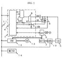
- FIG. 1 is a schematic configuration diagram showing an embodiment of a control device-for a vehicle or the like according to the invention.
- a vehicle control device (ECU 1) performs various controls, in a vehicle having a high-tension battery 2 mounted thereon, such as control of a battery charger 3, and includes a microcomputer 4 as a main component thereof.
- the ECU 1 is supplied from a low-tension battery 5 with a voltage BATT (12V) directly and always and a voltage VB via a power supply relay 7 operated in conjunction with a system starting switch (IGN 6).
- the voltage BATT and the voltage VB are respectively converted by a transformer 8 into about 5 V, which is supplied to elements in the ECU 1 such as the microcomputer 4, and clock IC 9.
- the power supply relay 7 has a configuration capable of supplying power by an OR circuit using a diode as shown in the figure, and can be turned on by way of an alarm output by the clock IC 9 or the microcomputer 4, in addition to the IGN 6. Diagnosis of the power supply by means of each output cannot be performed unless the other outputs are off.
- the microcomputer 4 is well known per se and includes a CPU, ROM, RAM, IO and the like.
- the microcomputer 4 in the ECU 1 transmits via a communication line 11 an instruction to an inverter 13 controlling a motor 12 or the battery charger 10 and an operation state to a meter 14.
- the microcomputer 4 is continuously fed with the power by the power supply relay 7 even if the IGN 6 is turned off, which allows the control to be continued even after the IGN 6 is turned off.
- the clock IC 9 continues to measure a time regardless of on/off of the IGN 6.
- the clock IC 9 outputs the measured time through serial communication to the microcomputer 4 in response to a request from the microcomputer 4.
- the clock IC 9 which has an alarm function starts up the microcomputer 4 at a scheduled time set before the IGN 6 is turned off to instruct the battery charger 3 through serial communication to charge the high-tension battery 2, or instruct the battery charger 10 through serial communication to charge the low-tension battery 5 using the electric power of the high-tension battery 2.
- Figure 2 is a flowchart showing an example of a program executed when the IGN 6 is turned on.
- step 100 the power supply relay 7 is turned on for ensuring the electric power to be fed even after the IGN 6 is turned off until the required processing is completed.
- step 101 the power supply diagnosis on start-up and the power supply function by means of an alarm signal shown in Figure 3 are checked.
- step 102 in Figure 2 whether or not the IGN 6 is turned off is determined, and if it is determined to be not turned off, at step 103 instruction arithmetic for vehicle control is performed through regular processing every 10 msecs with respect to the motor 12 and the battery charger 10, and at step 104 (first means) timer diagnosis shown in Figure 4 that is described later is performed.
- step 105 performs time processing at completion shown in Figure 5 that is described later, that is, the diagnosis on the power supply function by means of the alarm function, to turn off the power supply relay 7.
- step 106 whether or not the IGN 6 is turned on is monitored until the power supply is ceased, and if it is turned on, the process returns to step 100.
- step 110 it is determined whether or not at step 105 the diagnosis on the power supply function is completed with diagnosis of normality, and if it is not completed with diagnosis of normality, at step 111 failure is stored in the power supply function. Failure information is transmitted by the communication line 11 to the meter 14 to induce the driver to repair. At step 112, an alarm for the timer diagnosis at step 104 is set and activated.
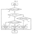
- step 120 whether or not the timer diagnosis is ended, is determined, and if not ended, at step 121 it is determined whether or not an alarm output has risen in a state where a timer coincides with the alarm set time.
- step 122 determines whether or not the risen alarm is in a range of the scheduled time, and "normality" is stored at step 123 in a case of being true and "abnormality” is stored at step 124 in a case of being false.
- the risen alarm is not cleared and is remained as it is for the time processing at completion at step 105 that is described later (second means).
- step 125 it is determined whether or not an alarm is not issued even though it is past the scheduled time, and "abnormality" is stored at step 126 in a case of being true. Abnormality information is transmitted by the communication line 11 to the meter 14 to induce the driver to repair.
- step 130 it is determined whether or not the meter 14 returns acknowledgement of receipt of a start notification responding to receipt of a notification of diagnosis start transmitted by the ECU 1. If the acknowledgement of receipt of the start notification is not returned, at step 131 the start notification of the power supply diagnosis is transmitted to the meter 14.
- step 132 assuming that the meter 14 monitors the power supply function by way of the alarm output by the clock IC 9, it is determined whether or not an output from the microcomputer 4 to the power supply relay 7 is turned off. In a case of being false, at step 133 the output from the microcomputer 4 to the power supply relay 7 is turned off to start to measure a lapse time.
- step 134 it is determined whether or not the lapse time is past an OK time, and in a case of being true, at step 135 (third means) stored is that the power supply function by way of the alarm output by the clock IC 9 is "normal", and "normality” is transmitted by the communication line 11 to the meter 14.
- the stored "normality” is used for determination at step 110.
- step 136 If at step 136 it is determined that acknowledgement of receipt of a "normality" notification is returned from the meter 14, at step 137 the alarm output by the clock IC 9 is cleared and the power supply relay 7 is turned off.
- FIG. 5 The flowchart shown in Figure 5 is a process associated with the meter 14, and therefore, processing of the meter 14 (monitor means) is shown in Figure 6 .
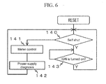
- step 140 in Figure 6 whether or not the meter 14 is stopped is determined, and if determined to be not stopped, at step 141 meter control is performed through regular processing every 10 msecs and at step 142 power supply diagnosis shown in Figure 7 that is described later is performed.
- step 143 If determined to be stopped, the process proceeds to step 143, and whether or not the IGN 6 is turned on is monitored until the power supply is ceased, and if it is turned on, the process returns to step 140.
- step 150 it is determined whether or not the diagnosis on the power supply function of the ECU 1 is completed. In a case of being false, at step 151 it is determined whether or not the start notification of the power supply diagnosis transmitted at step 131 is received. In a case of being true, at step 152 the receipt of the start notification is notified to the ECU 1.
- step 153 it is determined whether or not the "normality" notification transmitted at step 135 is received. In a case of being true, at step 154 the receipt of "normality" notification is notified to the ECU 1.
- step 155 it is determined whether or not the power supply function by means of the alarm function does not work and the time runs out because the ECU 1 is stopped. In a case of being true, it is determined at step 156 (by means for prohibiting devices from stopping) that the power supply function by means of the alarm function has a failure, and display and sound by the meter 14 induce the driver to repair.
- the battery charger 10 is instructed via the communication line 11 to continuously charge the low-tension battery 5 without stopping even during the IGN 6 is off.
- the vehicle control device (ECU 1) can diagnose the timer function in advance and remains the alarm output by the clock IC 9 which is output on diagnosis with no change to diagnose the power supply function in a short time. Even in the case of failure, the driver is induced to repair before he/she leaves a driver's seat, preventing poor charge of the high-tension battery 2 and low-tension battery 5 caused by unavailability of the alarm output.
- This embodiment is for an electric vehicle running on the electric power of the high-tension battery 2 charged by the battery charger 3, but also has a similar effect on an electric vehicle running on electric power generated by a fuel cell.
- the present invention is not limited to the control device (ECU) 1 for a vehicle, and can be applied to the diagnosis on the power supply function by means of the alarm output for a system which is started up at a desired time for controlling.
Landscapes
- Engineering & Computer Science (AREA)
- Power Engineering (AREA)
- Mechanical Engineering (AREA)
- Life Sciences & Earth Sciences (AREA)
- Sustainable Development (AREA)
- Sustainable Energy (AREA)
- Transportation (AREA)
- Human Computer Interaction (AREA)
- Electric Propulsion And Braking For Vehicles (AREA)
Abstract
Description
- The present invention relates to a control device for a vehicle or the like running on an electric motor, and particularly to a control device for a vehicle or the like which includes means for initiating power supply by way of an alarm signal output by a clock.
- For example, as disclosed in
Patent Literature 1, there have been known, as an electronic control device for a vehicle, those which measure a time during which a system starting switch is off and diagnose time measurement means by turning back a time or the like. - Patent Literature 1:
JP Patent Publication (Kokai) No. 2007-145235 - In the related art, whether or not measurement of a time during which a start signal for a vehicle is off is abnormal is diagnosed, but diagnosis needs to be made on a power supply function exerted by means of an alarm signal output issued after a predetermined time interval.
- An electric vehicle control device having at least a start signal for a vehicle and an alarm signal by a clock as means for initiating power supply, includes first means that checks an output of the alarm signal by the clock after start-up by the power supply, second means that holds the output of the alarm signal until start signals other than the alarm are all turned off, and third means that notifies of the power supply being continued by way of the alarm signal whose output is held after the start signals other than the alarm are turned off.
- The electric vehicle control device includes monitor means that has at least means that monitors a notification signal notifying of the power supply being continued, means that issues a warning by means of display or sound if there is no notification signal, and second power supply means different from the power supply means.
- The electric vehicle control device also includes means that prohibits devices from stopping if the monitor means issues a warning, the stopping being caused by the start signals other than the alarm being all turned off.
- According to the present invention, it is possible, in a case where an abnormality is found in a power supply function exerted by means of an alarm signal output issued after a predetermined time interval after a start signal for a vehicle is off, to inform of failure or switch over to a way where the relevant function is not used before a driver leaves the vehicle.
-
- [
Figure 1] Figure 1 is a schematic configuration diagram showing an embodiment of a control device for a vehicle or the like. - [
Figure 2] Figure 2 is a flowchart showing an example of a program executed when an IGN 6 is turned on. - [
Figure 3] Figure 3 is a flowchart showing power supply diagnosis processing on start-up. - [
Figure 4] Figure 4 is a flowchart showing a setting process procedure for checking an alarm function. - [
Figure 5] Figure 5 is a flowchart showing processing on an ECU side for diagnosis on the power supply function exerted by means of the alarm function. - [
Figure 6] Figure 6 is a flowchart showing processing by a meter. - [
Figure 7] Figure 7 is a flowchart showing processing on a meter side for diagnosis on the power supply function exerted by means of the alarm function. - Next, a description is given of embodiments of the invention with reference to the drawings.
- Hereinafter, a description is given of embodiments of a vehicle control device according to the invention with reference to the drawings.
-
Figure 1 is a schematic configuration diagram showing an embodiment of a control device-for a vehicle or the like according to the invention. A vehicle control device (ECU 1) according to this embodiment performs various controls, in a vehicle having a high-tension battery 2 mounted thereon, such as control of abattery charger 3, and includes amicrocomputer 4 as a main component thereof. TheECU 1 is supplied from a low-tension battery 5 with a voltage BATT (12V) directly and always and a voltage VB via a power supply relay 7 operated in conjunction with a system starting switch (IGN 6). In theECU 1, the voltage BATT and the voltage VB are respectively converted by a transformer 8 into about 5 V, which is supplied to elements in theECU 1 such as themicrocomputer 4, andclock IC 9. - The power supply relay 7 has a configuration capable of supplying power by an OR circuit using a diode as shown in the figure, and can be turned on by way of an alarm output by the
clock IC 9 or themicrocomputer 4, in addition to the IGN 6. Diagnosis of the power supply by means of each output cannot be performed unless the other outputs are off. - The
microcomputer 4 is well known per se and includes a CPU, ROM, RAM, IO and the like. - Hereafter, a description is given of a case as an example where the
ECU 1 turns off the system IGN 6 on the basis of a time measured by theclock IC 9, starts up at a scheduled time, and diagnoses whether or not the low-tension battery 5 can be charged by thebattery charger 10 using electric power of the high-tension battery 2. - The
microcomputer 4 in theECU 1 transmits via a communication line 11 an instruction to aninverter 13 controlling amotor 12 or thebattery charger 10 and an operation state to ameter 14. - The
microcomputer 4 is continuously fed with the power by the power supply relay 7 even if the IGN 6 is turned off, which allows the control to be continued even after the IGN 6 is turned off. - The
clock IC 9 continues to measure a time regardless of on/off of the IGN 6. Theclock IC 9 outputs the measured time through serial communication to themicrocomputer 4 in response to a request from themicrocomputer 4. - The
clock IC 9 which has an alarm function starts up themicrocomputer 4 at a scheduled time set before the IGN 6 is turned off to instruct thebattery charger 3 through serial communication to charge the high-tension battery 2, or instruct thebattery charger 10 through serial communication to charge the low-tension battery 5 using the electric power of the high-tension battery 2. - Hereinafter, a description is given of an example of a program (processing procedure) executed by the
microcomputer 4 which is associated with diagnosis on the power supply function by means of the alarm function from when the IGN 6 is turned on until after turned off with reference to flowcharts and the like inFigure 2 to Figure 5 . -
Figure 2 is a flowchart showing an example of a program executed when the IGN 6 is turned on. - Here, firstly, at
step 100, the power supply relay 7 is turned on for ensuring the electric power to be fed even after the IGN 6 is turned off until the required processing is completed. - At subsequent step 101, the power supply diagnosis on start-up and the power supply function by means of an alarm signal shown in
Figure 3 are checked. Atstep 102 inFigure 2 , whether or not the IGN 6 is turned off is determined, and if it is determined to be not turned off, atstep 103 instruction arithmetic for vehicle control is performed through regular processing every 10 msecs with respect to themotor 12 and thebattery charger 10, and at step 104 (first means) timer diagnosis shown inFigure 4 that is described later is performed. - If it is determined to be turned off, the process proceeds to
step 105 and performs time processing at completion shown inFigure 5 that is described later, that is, the diagnosis on the power supply function by means of the alarm function, to turn off the power supply relay 7. - At
step 106, whether or not the IGN 6 is turned on is monitored until the power supply is ceased, and if it is turned on, the process returns tostep 100. - Next, a description is given of power supply diagnosis processing on start-up executed at step 101 in
Figure 2 with reference to the flowchart shown inFigure 3 . - At
step 110, it is determined whether or not atstep 105 the diagnosis on the power supply function is completed with diagnosis of normality, and if it is not completed with diagnosis of normality, at step 111 failure is stored in the power supply function. Failure information is transmitted by the communication line 11 to themeter 14 to induce the driver to repair. At step 112, an alarm for the timer diagnosis at step 104 is set and activated. - A description is given of timer diagnosis processing executed at step 104 in
Figure 2 with reference to the flowchart shown inFigure 4 . - At
step 120, whether or not the timer diagnosis is ended, is determined, and if not ended, atstep 121 it is determined whether or not an alarm output has risen in a state where a timer coincides with the alarm set time. - If the condition at
step 121 is true, it is determined atstep 122 whether or not the risen alarm is in a range of the scheduled time, and "normality" is stored at step 123 in a case of being true and "abnormality" is stored at step 124 in a case of being false. The risen alarm is not cleared and is remained as it is for the time processing at completion atstep 105 that is described later (second means). - At step 125, it is determined whether or not an alarm is not issued even though it is past the scheduled time, and "abnormality" is stored at
step 126 in a case of being true. Abnormality information is transmitted by the communication line 11 to themeter 14 to induce the driver to repair. - A description is given of the time processing at completion executed at
step 105 inFigure 2 , that is, the diagnosis on the power supply function by means of the alarm function with reference to the flowchart shown inFigure 5 . - At step 130, it is determined whether or not the
meter 14 returns acknowledgement of receipt of a start notification responding to receipt of a notification of diagnosis start transmitted by theECU 1. If the acknowledgement of receipt of the start notification is not returned, at step 131 the start notification of the power supply diagnosis is transmitted to themeter 14. - At step 132, assuming that the
meter 14 monitors the power supply function by way of the alarm output by the clock IC 9, it is determined whether or not an output from themicrocomputer 4 to the power supply relay 7 is turned off. In a case of being false, at step 133 the output from themicrocomputer 4 to the power supply relay 7 is turned off to start to measure a lapse time. - At
step 134, it is determined whether or not the lapse time is past an OK time, and in a case of being true, at step 135 (third means) stored is that the power supply function by way of the alarm output by theclock IC 9 is "normal", and "normality" is transmitted by the communication line 11 to themeter 14. The stored "normality" is used for determination atstep 110. - If at step 136 it is determined that acknowledgement of receipt of a "normality" notification is returned from the
meter 14, atstep 137 the alarm output by theclock IC 9 is cleared and the power supply relay 7 is turned off. - The flowchart shown in
Figure 5 is a process associated with themeter 14, and therefore, processing of the meter 14 (monitor means) is shown inFigure 6 . - At
step 140 inFigure 6 , whether or not themeter 14 is stopped is determined, and if determined to be not stopped, at step 141 meter control is performed through regular processing every 10 msecs and atstep 142 power supply diagnosis shown inFigure 7 that is described later is performed. - If determined to be stopped, the process proceeds to step 143, and whether or not the
IGN 6 is turned on is monitored until the power supply is ceased, and if it is turned on, the process returns to step 140. - A description is given of the power supply diagnosis processing executed at
step 142 inFigure 6 , that is, the diagnosis on the power supply function by means of the alarm function with reference to the flowchart shown inFigure 7 . - At
step 150, it is determined whether or not the diagnosis on the power supply function of theECU 1 is completed. In a case of being false, at step 151 it is determined whether or not the start notification of the power supply diagnosis transmitted at step 131 is received. In a case of being true, at step 152 the receipt of the start notification is notified to theECU 1. - At step 153, it is determined whether or not the "normality" notification transmitted at
step 135 is received. In a case of being true, atstep 154 the receipt of "normality" notification is notified to theECU 1. - At step 155, it is determined whether or not the power supply function by means of the alarm function does not work and the time runs out because the
ECU 1 is stopped. In a case of being true, it is determined at step 156 (by means for prohibiting devices from stopping) that the power supply function by means of the alarm function has a failure, and display and sound by themeter 14 induce the driver to repair. Thebattery charger 10 is instructed via the communication line 11 to continuously charge the low-tension battery 5 without stopping even during theIGN 6 is off. - The vehicle control device (ECU 1) according to this embodiment as described above can diagnose the timer function in advance and remains the alarm output by the
clock IC 9 which is output on diagnosis with no change to diagnose the power supply function in a short time. Even in the case of failure, the driver is induced to repair before he/she leaves a driver's seat, preventing poor charge of the high-tension battery 2 and low-tension battery 5 caused by unavailability of the alarm output. - This embodiment is for an electric vehicle running on the electric power of the high-
tension battery 2 charged by thebattery charger 3, but also has a similar effect on an electric vehicle running on electric power generated by a fuel cell. - The present invention is not limited to the control device (ECU) 1 for a vehicle, and can be applied to the diagnosis on the power supply function by means of the alarm output for a system which is started up at a desired time for controlling.
-
- 1
- ECU
- 2
- high-tension battery
- 3
- battery charger
- 4
- microcomputer
- 5
- low-tension battery
- 6
- IGN
- 7
- power supply relay
- 8
- transformer
- 9
- clock IC
- 10
- battery charger
- 11
- communication line
- 12
- motor
- 13
- inverter
- 14
- meter
Claims (3)
- An electric vehicle control device having at least a start signal for a vehicle and an alarm signal by a clock as means for initiating power supply, comprising:first means that checks an output of the alarm signal by the clock after start-up by the power supply;second means that holds the output of the alarm signal until start signals other than the alarm are all turned off; andthird means that notifies of the power supply being continued by way of the alarm signal whose output is held after the start signals other than the alarm are turned off.
- The electric vehicle control device according to Claim 1, comprising:monitor means including at leastmeans that monitors a notification signal notifying of the power supply being continued,means that issues a warning by means of display or sound if there is no notification signal, andsecond power supply means different from the power supply means.
- The electric vehicle control device according to Claim 2, comprising:means that prohibits devices from stopping if the monitor means issues a warning, the stopping being caused by the start signals other than the alarm being all turned off.
Applications Claiming Priority (1)
| Application Number | Priority Date | Filing Date | Title |
|---|---|---|---|
| PCT/JP2012/075301 WO2014054089A1 (en) | 2012-10-01 | 2012-10-01 | Electric vehicle control device |
Publications (2)
| Publication Number | Publication Date |
|---|---|
| EP2905180A1 true EP2905180A1 (en) | 2015-08-12 |
| EP2905180A4 EP2905180A4 (en) | 2016-08-10 |
Family
ID=50434451
Family Applications (1)
| Application Number | Title | Priority Date | Filing Date |
|---|---|---|---|
| EP12885986.5A Withdrawn EP2905180A4 (en) | 2012-10-01 | 2012-10-01 | DEVICE FOR CONTROLLING AN ELECTRIC VEHICLE |
Country Status (4)
| Country | Link |
|---|---|
| US (1) | US20150258896A1 (en) |
| EP (1) | EP2905180A4 (en) |
| JP (1) | JP5974108B2 (en) |
| WO (1) | WO2014054089A1 (en) |
Families Citing this family (1)
| Publication number | Priority date | Publication date | Assignee | Title |
|---|---|---|---|---|
| JP7157873B2 (en) * | 2019-03-26 | 2022-10-20 | 日立Astemo株式会社 | Electronic control device, diagnostic method for electronic control device |
Family Cites Families (37)
| Publication number | Priority date | Publication date | Assignee | Title |
|---|---|---|---|---|
| JP2719240B2 (en) * | 1991-03-13 | 1998-02-25 | 三菱電機株式会社 | Automotive electronic control unit |
| AU1699499A (en) * | 1997-11-17 | 1999-06-07 | Lifestyle Technologies | Universal power supply |
| JPH11355904A (en) * | 1998-06-08 | 1999-12-24 | Honda Motor Co Ltd | Battery state detection device and battery state detection unit |
| JP2000116019A (en) * | 1998-10-06 | 2000-04-21 | Suzuki Motor Corp | Battery charge control device |
| JP2000293923A (en) * | 1999-04-08 | 2000-10-20 | Denso Corp | Power supply device for information processing device and information processing device |
| JP4355058B2 (en) * | 1999-07-27 | 2009-10-28 | 日本信号株式会社 | Power supply |
| JP2001076764A (en) * | 1999-09-07 | 2001-03-23 | Tokyo R & D Co Ltd | Motor-driven device having clock means |
| US6654648B2 (en) * | 2000-04-03 | 2003-11-25 | Toyota Jidosha Kabushiki Kaisha | Technique of monitoring abnormality in plurality of CPUs or controllers |
| JP3381708B2 (en) * | 2000-05-02 | 2003-03-04 | トヨタ自動車株式会社 | VEHICLE, POWER SUPPLY SYSTEM CONTROL DEVICE, POWER SUPPLY SYSTEM CONTROL METHOD, AND VEHICLE START-UP CONTROL METHOD |
| US7122979B2 (en) * | 2000-12-27 | 2006-10-17 | Transportation Techniques, Llc | Method and apparatus for selective operation of a hybrid electric vehicle in various driving modes |
| JP3839761B2 (en) * | 2001-09-14 | 2006-11-01 | 松下電器産業株式会社 | Battery control device |
| US20030236601A1 (en) * | 2002-03-18 | 2003-12-25 | Club Car, Inc. | Control and diagnostic system for vehicles |
| GB2397656A (en) * | 2003-01-21 | 2004-07-28 | Intelligent Battery Technology | Battery monitoring system |
| EP1595748B1 (en) * | 2003-02-17 | 2012-09-12 | Denso Corporation | Vehicle power supply system |
| US7332881B2 (en) * | 2004-10-28 | 2008-02-19 | Textron Inc. | AC drive system for electrically operated vehicle |
| JP2006304551A (en) * | 2005-04-22 | 2006-11-02 | Toyota Motor Corp | State determination system and vehicle |
| JP4685610B2 (en) | 2005-11-29 | 2011-05-18 | 日立オートモティブシステムズ株式会社 | Control devices for vehicles, etc. |
| JP4983487B2 (en) * | 2007-09-04 | 2012-07-25 | トヨタ自動車株式会社 | Vehicle control device |
| US8030881B2 (en) * | 2008-01-22 | 2011-10-04 | Honda Motor Co., Ltd. | Battery control system and method |
| US9026304B2 (en) * | 2008-04-07 | 2015-05-05 | United Parcel Service Of America, Inc. | Vehicle maintenance systems and methods |
| JP4573884B2 (en) * | 2008-06-18 | 2010-11-04 | 三菱電機株式会社 | In-vehicle electronic control unit power failure detection circuit |
| WO2010042517A1 (en) * | 2008-10-07 | 2010-04-15 | Boston-Power, Inc. | Li-ion battery array for vehicle and other large capacity applications |
| JP2010104175A (en) * | 2008-10-24 | 2010-05-06 | Panasonic Corp | Fault diagnosis circuit, power supply device, and fault diagnosis method |
| KR20120138733A (en) * | 2010-03-05 | 2012-12-26 | 파나소닉 주식회사 | Full charge capacity value correction circuit, battery pack, and charging system |
| JP5392180B2 (en) * | 2010-05-17 | 2014-01-22 | 日産自動車株式会社 | Safety measure control device for vehicle power failure |
| JP5644322B2 (en) * | 2010-09-28 | 2014-12-24 | 日産自動車株式会社 | Countermeasure device for inappropriate battery replacement of electric vehicle |
| WO2012063541A1 (en) * | 2010-11-09 | 2012-05-18 | 日本精工株式会社 | Power supply status diagnostic method and device |
| JP5460568B2 (en) * | 2010-12-17 | 2014-04-02 | 日立オートモティブシステムズ株式会社 | Control devices for vehicles, etc. |
| US9329239B2 (en) * | 2011-03-28 | 2016-05-03 | Sanyo Electric Co., Ltd. | Battery system, electric-powered vehicle, movable equipment, power storage device, and power source apparatus |
| US20120296512A1 (en) * | 2011-04-26 | 2012-11-22 | University Of Cincinnati | Method and system for electric vehicle battery prognostics and health management |
| AU2012258765B2 (en) * | 2011-05-24 | 2015-05-07 | Code 3, Inc. | Programmable control for siren and lights |
| JP5787997B2 (en) * | 2011-05-31 | 2015-09-30 | 日立オートモティブシステムズ株式会社 | Battery system monitoring device |
| US9235940B2 (en) * | 2011-08-26 | 2016-01-12 | Panasonic Intellectual Property Management Co., Ltd. | In-vehicle charger |
| US9365115B2 (en) * | 2012-01-20 | 2016-06-14 | Ford Global Technologies, Llc | System and method for vehicle power management |
| WO2013161067A1 (en) * | 2012-04-27 | 2013-10-31 | 日立ビークルエナジー株式会社 | Battery monitoring device and battery system monitoring device |
| US8571738B1 (en) * | 2012-06-13 | 2013-10-29 | Jtt Electronics Ltd | Automotive vehicle battery power system monitoring systems, apparatus and methods |
| EP2940827B1 (en) * | 2012-12-26 | 2020-05-06 | Mitsubishi Jidosha Kogyo Kabushiki Kaisha | Electric power supply device using electric vehicle |
-
2012
- 2012-10-01 US US14/431,987 patent/US20150258896A1/en not_active Abandoned
- 2012-10-01 WO PCT/JP2012/075301 patent/WO2014054089A1/en not_active Ceased
- 2012-10-01 JP JP2014539486A patent/JP5974108B2/en active Active
- 2012-10-01 EP EP12885986.5A patent/EP2905180A4/en not_active Withdrawn
Also Published As
| Publication number | Publication date |
|---|---|
| JPWO2014054089A1 (en) | 2016-08-25 |
| US20150258896A1 (en) | 2015-09-17 |
| WO2014054089A1 (en) | 2014-04-10 |
| EP2905180A4 (en) | 2016-08-10 |
| JP5974108B2 (en) | 2016-08-23 |
Similar Documents
| Publication | Publication Date | Title |
|---|---|---|
| JP5307685B2 (en) | Control device and control method for plug-in charging vehicle | |
| CN104114399B (en) | For detecting the device of the state of accumulator to be tested | |
| US8760093B2 (en) | Electronic control apparatus for a vehicle | |
| EP1832464A2 (en) | Reprogramming system and electronic control unit for hybrid vehicle | |
| US20170153281A1 (en) | Method for checking a connection between a low-voltage supply system and a battery, and motor vehicle | |
| US20050269170A1 (en) | Vehicle power source device | |
| US20130054085A1 (en) | Detection circuit for open or intermittent motor vehicle battery connection | |
| JP2010193670A (en) | Charging apparatus and method, and program | |
| KR102481210B1 (en) | Method for checking high voltage battery status in sleep mode of electric vehicle | |
| JP2010180776A (en) | Power source control device | |
| US20220111757A1 (en) | Battery diagnostic device, method, program, and vehicle | |
| US7305283B2 (en) | On-vehicle electronic control device | |
| CN110259618B (en) | Starter monitoring method and device | |
| EP3321135A1 (en) | Vehicle control device | |
| CN105073476B (en) | Monitoring device for motor vehicle and method for monitoring motor vehicle | |
| JP2021059273A (en) | On-vehicle communication system and power source control method | |
| EP2284379B1 (en) | Internal combustion engine controller | |
| JP5460568B2 (en) | Control devices for vehicles, etc. | |
| US20150258896A1 (en) | Electric Vehicle Control Device | |
| CN110221208B (en) | Generator performance detection system and method based on engine test bench | |
| US12055594B2 (en) | Measurement system and method for determining a status of a power system in a vehicle using the measurement system | |
| JP2011058997A (en) | Battery state detection system | |
| KR101345036B1 (en) | Apparatus and method for charging battery of an vehicle automatically | |
| JP2015112962A (en) | Information processing apparatus | |
| JP6163118B2 (en) | Vehicle control device |
Legal Events
| Date | Code | Title | Description |
|---|---|---|---|
| PUAI | Public reference made under article 153(3) epc to a published international application that has entered the european phase |
Free format text: ORIGINAL CODE: 0009012 |
|
| 17P | Request for examination filed |
Effective date: 20150504 |
|
| AK | Designated contracting states |
Kind code of ref document: A1 Designated state(s): AL AT BE BG CH CY CZ DE DK EE ES FI FR GB GR HR HU IE IS IT LI LT LU LV MC MK MT NL NO PL PT RO RS SE SI SK SM TR |
|
| AX | Request for extension of the european patent |
Extension state: BA ME |
|
| DAX | Request for extension of the european patent (deleted) | ||
| RIC1 | Information provided on ipc code assigned before grant |
Ipc: B60L 3/12 20060101AFI20160630BHEP Ipc: B60R 16/02 20060101ALI20160630BHEP |
|
| RA4 | Supplementary search report drawn up and despatched (corrected) |
Effective date: 20160707 |
|
| STAA | Information on the status of an ep patent application or granted ep patent |
Free format text: STATUS: EXAMINATION IS IN PROGRESS |
|
| 17Q | First examination report despatched |
Effective date: 20191209 |
|
| STAA | Information on the status of an ep patent application or granted ep patent |
Free format text: STATUS: THE APPLICATION IS DEEMED TO BE WITHDRAWN |
|
| 18D | Application deemed to be withdrawn |
Effective date: 20200603 |