EP2905179A1 - A load carrier foot - Google Patents
A load carrier foot Download PDFInfo
- Publication number
- EP2905179A1 EP2905179A1 EP14154337.1A EP14154337A EP2905179A1 EP 2905179 A1 EP2905179 A1 EP 2905179A1 EP 14154337 A EP14154337 A EP 14154337A EP 2905179 A1 EP2905179 A1 EP 2905179A1
- Authority
- EP
- European Patent Office
- Prior art keywords
- bracket
- load carrier
- carrier foot
- brackets
- vehicle
- Prior art date
- Legal status (The legal status is an assumption and is not a legal conclusion. Google has not performed a legal analysis and makes no representation as to the accuracy of the status listed.)
- Granted
Links
Images




Classifications
-
- B—PERFORMING OPERATIONS; TRANSPORTING
- B60—VEHICLES IN GENERAL
- B60R—VEHICLES, VEHICLE FITTINGS, OR VEHICLE PARTS, NOT OTHERWISE PROVIDED FOR
- B60R9/00—Supplementary fittings on vehicle exterior for carrying loads, e.g. luggage, sports gear or the like
- B60R9/04—Carriers associated with vehicle roof
- B60R9/058—Carriers associated with vehicle roof characterised by releasable attaching means between carrier and roof
Definitions
- a load carrier foot of clamping type comprising a support surface, a bracket and a tensioning arrangement to impart a clamping force between the support surface and the bracket.
- the tensioning arrangement comprises a lever and can be operated by a user using his/hers hands.
- Roof racks for vehicles are during use exposed to very harsh environmental conditions such as rain, snow, wind, dirt and the like. They are further expected to withstand a high amount of crash violence, e.g. from a colliding vehicle. These requirements impede restrictions to the materials selected, the shape and the form of the roof rack and its components.
- a roof rack generally has a first and a second load carrier foot and a load carrying bar extending there between. It is important that the load carrier feet are mounted and attached correctly to the vehicle roof.
- Different types of load carrier feet have been developed.
- One type of load carrier foot is a fix-point load carrier foot.
- a fix-point load carrier foot uses fixed positions on the vehicle roof to attach the load carrier foot.
- a nut welded to the vehicle roof, or welded to the vehicle roof chassi serves as a fixed anchoring point for a fix-point load carrier foot.
- a draw back with a fix-point load carrier foot is of course the limited amount of available positions at which the load carrier foot can be positioned.
- load carrier foot is a load carrier foot of clamping type.
- Such a load carrier foot uses clamping force between a support surface and a bracket as main attachment principle.
- An advantage with this type of load carrier foot is that they can be positioned in a plurality of different positions, generally along a rail arranged on the roof of the vehicle.
- Load carrier feet of clamping type are however susceptible to some drawbacks.
- a load carrier foot of clamping type is disclosed in the US patent no. US 5,492,258, Happich GMBH .
- One drawback is that they generally tend to use the friction provided by the clamping force to rely on a sturdy attachment to the vehicle rail, or vehicle roof.
- a load carrier foot comprising a support body comprising a support surface adapted to rest against a first surface of a vehicle.
- a first bracket adapted to grip about a second surface of the vehicle, a second bracket adapted to grip about a third surface of the vehicle, and a tensioning arrangement adapted to impart a clamping force at between the support surface and the first and the second brackets to retain the load carrier foot to the vehicle.
- each of the first and the second brackets is pivotally connected to each other.
- each of the first and the second brackets comprises at least two connection flanges, and in that the connection flanges of the first bracket are positioned adjacent the connection flanges of the second bracket.
- the load carrier foot has a very favourable and strong connection to the vehicle as the tensioning arrangement together with a first and a second brackets and a support surface of the support body form a three-point force component attachment configuration, each force component having a direction which is different with respect to each other.
- At least one of the first and the second brackets are pivotally connected to the support body of the load carrier foot.
- One bracket or both brackets can be pivotally connected to the support body of the load carrier foot.
- the first bracket is pivotally connected to the support body of the load carrier foot and the second bracket is pivotally connected to the first bracket.
- the first and the second brackets can be pivotally connected to the support body at one or more common connection points.
- One common connection point, or connection axle is advantageous as it simplifies the assembly of the load carrier foot and reduces the amount of individual components of the load carrier foot. It is also advantageous as the first and the second brackets are pivotally connected to each other and to the support body of the load carrier foot at one common point, using a common axle.
- the first and the second brackets are preferably formed by sheet steel, such as pressed sheet steel.
- the support body of the load carrier foot is also preferably made from sheet steel. Composites and reinforced plastic material may be used.
- the first and the second brackets can be pivotally connected to the support body using one or more common connection axles. It is possible that the first and the second brackets are connected to the support body of the load carrier foot using two axles aligned with each other, or as disclosed herein, one single axle.
- the first and the second brackets each has a first end forming a gap there between, the gap being adapted to receive a portion of the vehicle, such as a rail of the vehicle.
- the first bracket and/or the second bracket can be connected using a circular aperture through which a connection axle extends.
- the first and/or the second brackets comprises an elongated aperture for receiving the connection axle.
- the first and/or the second brackets can be displaceable a distance defined by the elongated aperture of the first bracket and the connection axle.
- the displacement of the first and/or the second brackets are dependent on the available play between the connection axle and the aperture. It is possible that only one of first or the second brackets are provided with an elongated aperture so as to permit the bracket to be displaced a limited distance, the other bracket may be provided with a circular aperture, preferably having a diameter only lightly larger than the diameter of the connection axle.
- the elongated aperture of the first bracket can have an extension which is longer than the extension of the elongated aperture of the second bracket.
- the tensioning arrangement is arranged to clamp, or operate, on the first and the second brackets on a position between the gap and the one or more common connection points.
- the tensioning arrangement can comprise an elongated member, such as a screw or bolt, extending between the first and the second brackets.
- a cam member connected to the elongated member can be connected to the elongated member.
- the cam member is adapted to impart a clamping force between the first and the second brackets.
- the cam member is preferably adapted to translate a rotational motion of the cam member to a forward motion of the bracket on which the cam member operates with the purpose of reducing the distance between the first and the second brackets.
- the first and the second brackets can be provided with at least one connection flange at which the first and the second brackets are connected.
- the at least one connection flange of the first and the second brackets can be positioned substantially adjacent each other, preferably adjacent each other.
- connection flanges which are positioned adjacent each other the first and the second brackets forms a layered section, or a laminate or sandwich structure. The adjacent layers provide stability to the load carrier foot.
- connection flange of the first and/or the second brackets and a portion of the support body can positioned substantially adjacent each other, preferably adjacent each other.
- a three layered structure is provided in this manner. If each bracket comprises two connection flanges, a double three layered structure or section is provided.
- Each bracket can comprise two or more connection flanges.
- the connection flanges of the first and the second brackets can be provided with elongated apertures as disclosed herein.
- connection flange extends from a main portion of the first and/or the second brackets and is advantageously arranged substantially perpendicular to the main portion.
- Each bracket i.e. both the first and the second brackets can thus be provided with two parallel connection flanges extending out from a main portion of the bracket.
- the first and/or the second the two connection flanges is arranged at opposing sides of the main portion of the first and the second bracket. If a bracket used for the load carrier foot described herein has three connection flanges, a suitable cross section could be an E-shaped cross section, i.e. having three parallel connection flanges extending out from a main portion of the bracket. When having only two connection flanges, the centrally arranged connection flange will be omitted.
- the load carrier foot can comprise a secondary support body.
- a secondary support body can advantageously be positioned between a portion of the first and/or the second bracket. Such portion is preferably a connection flange of the first and/or the second bracket.
- FIG. 1 shows a load carrier foot 1 and parts of a load carrying bar 2.
- the load carrier foot 1 comprises a support body 3 to which the load carrying bar 2 is arranged.
- the support body 3 further comprises a support surface 4 adapted to rest against a first surface of a vehicle (not shown).
- the first surface of the vehicle can be a rail, or any surface on the roof, or any other suitable surface of the vehicle.
- the support surface 4 can be formed by an individual support member 5 as in the shown embodiment, or it can be integrally formed with the support body 3.
- a support member, like the support member 5, is preferably manufactured from a tough but lenient material having some elasticity and which is slightly compressible.
- a suitable material is rubber or a rubber like material, a thermoplastic material such as a polypropylene, or polyethylene based material. It is intended to provide for an increased friction between a support body of the load carrier foot, and the vehicle, e.g. a rail or the vehicle roof. It is further intended to prevent the rail or the vehicle roof from damage through tear and wear.
- the support member 5 can be mated with the support body 3 via protruding members and apertures on the support body 3, to retain the support member 5 to the support body 3.
- a first bracket 6, or grip arm is adapted to cooperate, e.g. grip about, a first surface of the vehicle, to retain the load carrier foot 1 to the vehicle.
- the load carrier foot 1 further comprises a second bracket 6' which is adapted to cooperate, e.g. grip about, a second surface of the vehicle, to retain the load carrier foot 1 to the vehicle.
- a tensioning arrangement 10 is adapted to impart the first bracket 6 and the second bracket 6' with a force so that a clamping force is formed between the first bracket 6, the second bracket 6' and the support surface 4, enabling them to cooperate in a clamping manner to retain the load carrier foot 1 to the vehicle.
- the support body 3 of the load carrier foot 1 carries the weight of the load and the load carrying bar 2 via the support surface 4.
- the first and the second brackets 6, 6' are pivotally connected to the support body 3, in the shown embodiment using a common connection axle 7.
- the tensioning arrangement 10, the first and the second brackets 6, 6' together with the support surface 4 provides for a tree point clamping function.
- the tree point clamping function clamps about the vehicle, in the shown embodiment about a rail of the vehicle, at three points or areas, and with three force components having different directions. Each point thus has a force component acting in a direction separate from the other two points during use.
- Figure 2 shows the first and the second brackets 6, 6' in greater detail.
- Figure 2 shows the connection axle 7 and a biasing member in the form of a spring 9, in this case a helical spring.
- the first bracket 6 and the second bracket 6' form a jaw like arrangement with a gap when seen as shown in figure 2 .
- the biasing member 8 is adapted to bias the first and the second brackets 6, 6' away from each other, i.e. to keep the gap formed between the first and the second brackets 6, 6' open.
- Each of the brackets 6, 6' comprises an end 6a, 6'a defining the gap between the first and the second brackets 6, 6'.
- the end 6'a of the second bracket 6' comprises a pin 6'b which is intended to be received in a cavity on the rail of the vehicle.
- the second bracket 6' can be similar or identic with the first bracket 6 however if desired.
- the support member 5, shown in figure 1 has pockets 5a, 5b for receiving the ends 6a, 6'a of the first and the second brackets 6, 6' respectively.
- Figure 3 shows figure 2 in an exploded view.
- the first and the second brackets 6, 6' has an upper and a lower portion 6u, 6l, 6'u, 6'l.
- the upper portions 6u, 6'u of the first and the second brackets 6, 6' each comprises connection flanges 10, 11, 10', 11'.
- the connection flanges 10, 11, 10', 11' extends substantially perpendicular out from a main portion 6m, 6'm of the first and the second brackets 6, 6'.
- the main portion 6m and the two connection flanges 10, 11 of the first bracket thus 6 forms a U-like section adapted to mesh with the corresponding U-like section of the opposing second bracket 6' to provide rigidity to the first and the second brackets 6, 6' and the load carrier foot 1.
- the main portion of the first and the second brackets 6, 6' transcends to a grip portion 6gp, 6'gp, which is that part of the first and the second brackets which is intended to grasp about a portion of the vehicle.
- the grip portions 6gp, 6'gp can have different configurations as shown in the figure, or have the same configuration.
- the load carrier foot 1 thus has sections with overlapping material layers which are believed to structurally support the load carrier foot 1.
- connection flanges 10, 11, 10', 11' of the first and the second brackets 6, 6' comprises an elongated aperture 13, 13', also referred to as connection apertures.
- the elongated apertures 13, 13' are adapted to receive the connection axle 7 and pivot about the connection axle 7 so that the load carrier foot 1 is easy to mount and dismount. Further, the elongation of the elongated apertures 13, 13' permit the connection axle 7 to be displaced a distance defined by the elongation of the elongated apertures 13, 13'. As is noticed the elongated apertures 13, 13' have a width W which is slightly larger than the diameter of the connection axle 7.
- the width W is large enough to permit the connection axle 7 to slide inside of the elongated apertures 13, 13', but not too large so that unnecessary play is formed between the connection axle 7 and the sides of the elongated apertures 13, 13'.
- the length of the elongated apertures 13 of the first bracket 6 is slightly shorter than the elongation of the length of the elongated aperture 13 of the second bracket 6'.
- a suitable length of an elongated aperture 13, 13' is between 5-50 mm, optionally at least 1.5 times the length of the diameter of the connection axle.
- One or both of the first and the second brackets 6, 6' can be connected using an elongated aperture having an elongated extension as described above.
- the elongated apertures 13, 13' are further tilted with respect to each other. This will pull the first and the second bracket upwards when the tensioning arrangement 10 is used.
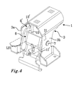
- Figure 4 shows portions of the load carrier foot 1.
- Figure 4 shows the support body 3, the connection axle 7 and the first and the second bracket 6, 6'. From left to right, the layers formed by each component is the support body 3, a first connection flange 10' of the second bracket 6', a first connection flange 10 of the first bracket 6, between the two connection flanges 10, 11 of the first bracket 6 is the biasing member 8 positioned in this case the spring 9 (not shown), thereafter the second connection flange 11 of the first bracket 6, the second connection flange 11' of the second bracket 6' and finally again the support body 3.
- the load carrier foot 1 has a first and a second layered section LS1, LS2, each section is formed by three components.
- a layered section the support body 3, the first bracket 6 and the second bracket 6' are positioned adjacent each other in a sandwich structure. It is possible that a washer may be positioned between each material layer, it is still considered to be a layered section.
- the layered sections LS1, LS2 give the load carrier foot 1 enhanced stability and rigidity which is very important, especially during crash scenarios. It is believed without being bound by theory that the individual components in the layered sections support each other. Further, by using a common connection axle, such as the connection axle 7, an even better stability is provided to the load carrier foot 1.
- the support body 3 has a first and a second side 3a, 3b.
- the support body 3 of the load carrier foot 1 has a U-shaped form, with the two sides 3a, 3b forming vertical walls on which the first and the second bracket 6, 6' are positioned to brace against.
- the first layered section LS1 is defined by the first side 3a of the support body 3 positioned adjacent the first connection flange 10 of the second bracket 6' which in turn is positioned adjacent the first connection flange 10 of the first bracket 6.
- the second layered section LS2 is defined by the second connection flange 11 of the first bracket 6 which in turn is positioned adjacent the second connection flange 11' of the second bracket 6' which in turn is positioned adjacent the second side 3b of the support body 3.
- two layered sections with three layers are formed. In the layered section described herein, one layer is stationary and two layers are displaceble with respect to each other. After the load carrier foot 1 has been positioned on the vehicle roof, the support body 3 of the load carrier foot 1 is stationary and only the first and the second brackets are displaceable enough to tighten the brackets towards each other.
- first and the second brackets 6, 6' has two connection flanges 10, 11, 10', 11'
- the load carrier foot 1 can be provided with a first and a second bracket having only one connection flange, thus forming only one layered section.
- connection flanges do not necessarily be positioned adjacent a side of the support body, as shown in figure 3 . It may suffice that the connection flanges of the brackets are positioned adjacent each other, or that a connection flange of one bracket is positioned adjacent one side of the support body. In the just mentioned embodiment, a layered section with two layers is formed.
- the first and the second brackets 6, 6' can be formed by sheet steel, such as pressed sheet steel.
- the support body 3 of the load carrier foot 1 can also be formed from sheet steel.
- Composites and reinforced plastic material may be used as alternative or in addition to sheet steel.
- the load carrier foot 1 is retained to the vehicle using the first and the second brackets 6, 6'.
- a tensioning arrangement 10 is extending between the first and the second brackets 6, 6' which can be operated to permit the load carrier foot 1 to be mounted to a rail of a vehicle, and to permit the load carrier foot 1 to be dismounted from the rail of the vehicle.
- connection flanges 10, 10', 11', 11' of the first and the second brackets 6, 6' are arranged on the inside of the support body 3, i.e. between the first and the second sides 3a, 3b of the support body 3.
- the support body 3 is arranged between the connection flanges of the first and/or the second brackets 6, 6'.
- the load carrier foot 1 can further be provided with a secondary support body (not shown) arranged between the first connection flange 10 and the second connection flange 11 of the first bracket 6.
- a secondary support body would provide additional support surface to the vehicle, or support member, and towards the load carrying bar receiving portion of the support body 3.
- the load carrier foot 1 would in such an embodiment be provided with two 'four layered sections'.
- the connection axle 7 would in such an embodiment extend through apertures on the secondary support body in a similar manner as in the connection flanges, although such apertures would have a diameter just slightly larger than the diameter of the connection axle 7.
- Figure 5 shows the load carrier foot 1 in exploded view.
- Figure 5 shows the support body 3, the support member 5, the first and the second bracket 6, 6', the connection axle 7 and the biasing member 8 in the form of a spring 9.
- Figure 5 further shows the tensioning arrangement 10.
- the tensioning arrangement 10 in the shown embodiment comprises a cam member 11, a release member 12, a lever 13, a screw 30 and a first and a second pin 23, 23'.
- the pin 23 comprises an aperture 24 which can be connected to the cam member 11 via an aperture 24 '.
- the aperture 24 of the pin 23 is adapted to receive the screw 30 making the screw 30 pivotally connected to the cam member 11.
- the screw 30 comprises a threaded end 31 and a head 32.
- the threaded end 31 is adapted to be threadably engaged with the pin 23'.
- the pin 23' has a T-shaped form so that it is permitted to engage the second bracket 6' while still permit the length of the screw 30 to be adjusted if desired.
- tensioning arrangement 10 will be described in greater detail hereafter with reference to a load carrier foot 1 similar to the load carrier foot 1 shown in figure 1 but with a slightly modified cam member 11 and lever 13.
- Figure 6 shows a cross section of the load carrier foot 1.
- the lever 13 is positioned in a storage position, or in a ready to mount position, and the cam member 11 is in a released position.
- the load carrier foot 1 is ready to be mounted to a rail of a vehicle, the brackets 6, 6' are "opened” in the sense that the distance between the ends 6a, 6'a of the brackets 6, 6' are separated a distance D1, enough for the load carrier foot 1 to be mounted to the rail of the vehicle in an easy manner.
- Figure 6 shows the support body 3, the first bracket 6, the second bracket 6', the connection axle 7 and the biasing member 8 in the form of a spring 9.
- the load carrying bar is not shown in figure 6 .
- the cam member 11 is intended to press or brace against the first bracket 6 to impart the clamping force and operates as an eccentric in terms of that the rotational motion of the lever 13 is transferred to a displacement of the first bracket 6 towards the second bracket 6', i.e. a translation of the first bracket 6 with respect to the second bracket 6' is achieved.
- the cam member 11 comprises a cam surface 40, or eccentric surface, adapted to brace against a surface of the first bracket 6.
- the cam surface 40 has a convex form with respect to the first bracket 6, as shown in figure 6 .
- the cam surface 40 has a radius curvature.
- the first and the second brackets 6, 6' Due to the angle of the elongated apertures 13 of the first and the second brackets 6, 6', by which the first and the second brackets 6, 6' are connected to the support body 3, the first and the second brackets 6, 6' are also displaced slightly upwards as indicated with the arrow B. As a result, the load carrier foot 1 is readily retained e.g. to a rail of the vehicle.
- the release member 12 is pushed in a counter clock wise direction, as shown in figure 9 whereby the release member 12 displaces the cam member 11 from the tightened position.
- the release member 12 can be integrally formed with the lever 13 or be pivotally connected to the lever 13.
- the release member 12 is configured to release the imparted pressure by the cam member 11.
- the lever 13 is formed by form molded plastic but could be formed by a bent rod or in a variety of different forms and shapes. The purpose is to provide a user with a grip by which the user can impart the necessary force to the cam member 11, a force high enough for the cam member 11 to rotate and translate the rotational motion to a displacement of the first bracket 6 relative to the second bracket 6'.
- the cam member 11 and the lever 13 are pivotally connected to each other.
- a pin 23 with an aperture 24 is pivotally connected to the cam member 11.
- the aperture 24 of the pin 23 is adapted to receive a screw 30, making the screw 30 pivotally connected to the cam member 11.
- the cam member 11 is pivotally arranged to the first bracket 6 via screw 30 and configured to impart the first bracket 6 with a force upon rotation of the cam member 11 using the lever 13.
- the cam member 11 is arranged in a cavity 40 of the first bracket 6.
- the cavity 40 provides the cam member 11 with a ridge 42 to which the cam member 11 can use as cam surface and brace towards.
- the screw 30 extends through an aperture 41 arranged in the cavity 40 of the first bracket 6.
- the aperture 41 extends across the ridge 42 so that the screw 30 can be displaced between different positions along the length of the aperture 41 of the first bracket 6 as will be described below.
- a cam member such as the cam member 11 disclosed herein, is advantageously selected from a material which can withstand wear, tear and the torque imparted by the user.
- a strong plastic material or a reinforced plastic material can be used, optionally a metal preferably steel or aluminum.
- the screw 30 comprises a threaded end 31 and a head 32.
- the threaded end 31 is adapted to be threadably engaged with a second pin 23', similar to the pin 23.
- the second pin 23' can be attached by other means such as by welding, pinching or the like.
- the second pin 23' is however pivotable with respect to the second bracket 6'. In the shown embodiment, the second pin 23' is not attached to the second bracket 6' but retained thereto by means of the screw 30.
- the second bracket 6' also comprises a cavity 40' formed by a portion of the bracket 6'.
- the second pin 23' is arranged in the cavity 40'.
- the cavity 40' extends towards the first bracket 6, and thus forms a protrusion on the first bracket facing side of the second bracket 6'.
- An aperture 41' is arranged substantially in the cavity 40'.
- the screw 30 further extends through the aperture 41' arranged in the second bracket 6'.
- the aperture 41' substantially extends across the cavity 40' permitting the screw 30 to pivot, or at least across what is to be considered as the bottom, of the cavity 40'.
- the load carrier foot 1 shown in figures 1-7 has two brackets 6, 6'.
- each of the two brackets 6, 6' has a cavity 40, 40' comprising an aperture 41, 41' for receiving a portion of the tensioning arrangement 10.
- One cavity, in this case the cavity 40' of the second bracket 6', is arranged in working cooperation with one end of the screw, and the other cavity, in this case the cavity 40 of the first bracket 6 is in working cooperation with the cam member 11 of the tensioning arrangement 10.
Landscapes
- Engineering & Computer Science (AREA)
- Mechanical Engineering (AREA)
- Fittings On The Vehicle Exterior For Carrying Loads, And Devices For Holding Or Mounting Articles (AREA)
Abstract
Description
- A load carrier foot of clamping type comprising a support surface, a bracket and a tensioning arrangement to impart a clamping force between the support surface and the bracket. The tensioning arrangement comprises a lever and can be operated by a user using his/hers hands.
- Roof racks for vehicles are during use exposed to very harsh environmental conditions such as rain, snow, wind, dirt and the like. They are further expected to withstand a high amount of crash violence, e.g. from a colliding vehicle. These requirements impede restrictions to the materials selected, the shape and the form of the roof rack and its components.
- A roof rack generally has a first and a second load carrier foot and a load carrying bar extending there between. It is important that the load carrier feet are mounted and attached correctly to the vehicle roof. Different types of load carrier feet have been developed. One type of load carrier foot is a fix-point load carrier foot. A fix-point load carrier foot uses fixed positions on the vehicle roof to attach the load carrier foot. Usually a nut welded to the vehicle roof, or welded to the vehicle roof chassi, serves as a fixed anchoring point for a fix-point load carrier foot. A draw back with a fix-point load carrier foot is of course the limited amount of available positions at which the load carrier foot can be positioned.
- Another type of load carrier foot is a load carrier foot of clamping type. Such a load carrier foot uses clamping force between a support surface and a bracket as main attachment principle. An advantage with this type of load carrier foot is that they can be positioned in a plurality of different positions, generally along a rail arranged on the roof of the vehicle. Load carrier feet of clamping type are however susceptible to some drawbacks. A load carrier foot of clamping type is disclosed in the US patent no.
US 5,492,258, Happich GMBH . One drawback is that they generally tend to use the friction provided by the clamping force to rely on a sturdy attachment to the vehicle rail, or vehicle roof. There is also the risk of a load carrier foot of clamping type not being mounted correctly. The ease of which a load carrier foot can be mounted and the semantics which is projected to a user are important factors to reduce the risk of a user mounting a load carrier foot of clamping type incorrectly. - Further, using tools is considered less favorable when mounting load carrier foots. Tools are not always at hand, and tools further increase the risk of imparting to high amount of torque when tightening, e.g. tightening a screw on a load carrier foot to tight. It is thus advantageous to provide a load carrier foot which can be operated by a user using his/hers hands as a complement or replacement to tools
- It is an object of the present invention to reduce at least one of the drawbacks of the prior art, or to provide for a useful alternative. The objects are at least partly met by a load carrier foot comprising a support body comprising a support surface adapted to rest against a first surface of a vehicle. A first bracket adapted to grip about a second surface of the vehicle, a second bracket adapted to grip about a third surface of the vehicle, and a tensioning arrangement adapted to impart a clamping force at between the support surface and the first and the second brackets to retain the load carrier foot to the vehicle.
- The first and the second brackets are pivotally connected to each other. Optionally or additionally each of the first and the second brackets comprises at least two connection flanges, and in that the connection flanges of the first bracket are positioned adjacent the connection flanges of the second bracket.
- The load carrier foot has a very favourable and strong connection to the vehicle as the tensioning arrangement together with a first and a second brackets and a support surface of the support body form a three-point force component attachment configuration, each force component having a direction which is different with respect to each other.
- According to an embodiment, at least one of the first and the second brackets are pivotally connected to the support body of the load carrier foot. One bracket or both brackets can be pivotally connected to the support body of the load carrier foot. In an embodiment, the first bracket is pivotally connected to the support body of the load carrier foot and the second bracket is pivotally connected to the first bracket.
- The first and the second brackets can be pivotally connected to the support body at one or more common connection points. One common connection point, or connection axle, is advantageous as it simplifies the assembly of the load carrier foot and reduces the amount of individual components of the load carrier foot. It is also advantageous as the first and the second brackets are pivotally connected to each other and to the support body of the load carrier foot at one common point, using a common axle.
- The first and the second brackets are preferably formed by sheet steel, such as pressed sheet steel. The support body of the load carrier foot is also preferably made from sheet steel. Composites and reinforced plastic material may be used.
- The first and the second brackets can be pivotally connected to the support body using one or more common connection axles. It is possible that the first and the second brackets are connected to the support body of the load carrier foot using two axles aligned with each other, or as disclosed herein, one single axle.
- The first and the second brackets each has a first end forming a gap there between, the gap being adapted to receive a portion of the vehicle, such as a rail of the vehicle.
- The first bracket and/or the second bracket can be connected using a circular aperture through which a connection axle extends. As an option, the first and/or the second brackets comprises an elongated aperture for receiving the connection axle. By using an elongated aperture, the first and/or the second brackets can be displaceable a distance defined by the elongated aperture of the first bracket and the connection axle. The displacement of the first and/or the second brackets are dependent on the available play between the connection axle and the aperture. It is possible that only one of first or the second brackets are provided with an elongated aperture so as to permit the bracket to be displaced a limited distance, the other bracket may be provided with a circular aperture, preferably having a diameter only lightly larger than the diameter of the connection axle.
- The elongated aperture of the first bracket can have an extension which is longer than the extension of the elongated aperture of the second bracket.
- The tensioning arrangement is arranged to clamp, or operate, on the first and the second brackets on a position between the gap and the one or more common connection points.
- The tensioning arrangement can comprise an elongated member, such as a screw or bolt, extending between the first and the second brackets. A cam member connected to the elongated member can be connected to the elongated member. The cam member is adapted to impart a clamping force between the first and the second brackets. The cam member is preferably adapted to translate a rotational motion of the cam member to a forward motion of the bracket on which the cam member operates with the purpose of reducing the distance between the first and the second brackets.
- The first and the second brackets can be provided with at least one connection flange at which the first and the second brackets are connected. The at least one connection flange of the first and the second brackets can be positioned substantially adjacent each other, preferably adjacent each other. By having connection flanges which are positioned adjacent each other, the first and the second brackets forms a layered section, or a laminate or sandwich structure. The adjacent layers provide stability to the load carrier foot.
- The at least one connection flange of the first and/or the second brackets and a portion of the support body can positioned substantially adjacent each other, preferably adjacent each other. A three layered structure is provided in this manner. If each bracket comprises two connection flanges, a double three layered structure or section is provided.
- Each bracket can comprise two or more connection flanges. The connection flanges of the first and the second brackets can be provided with elongated apertures as disclosed herein.
- The at least one connection flange extends from a main portion of the first and/or the second brackets and is advantageously arranged substantially perpendicular to the main portion. Each bracket, i.e. both the first and the second brackets can thus be provided with two parallel connection flanges extending out from a main portion of the bracket.
- The first and/or the second the two connection flanges is arranged at opposing sides of the main portion of the first and the second bracket. If a bracket used for the load carrier foot described herein has three connection flanges, a suitable cross section could be an E-shaped cross section, i.e. having three parallel connection flanges extending out from a main portion of the bracket. When having only two connection flanges, the centrally arranged connection flange will be omitted.
- The load carrier foot can comprise a secondary support body. A secondary support body can advantageously be positioned between a portion of the first and/or the second bracket. Such portion is preferably a connection flange of the first and/or the second bracket.
- Non-limiting embodiments of the present invention will be described in greater detail with reference to the accompanying drawings in which;
-
figure 1 shows a load carrier foot according to a first embodiment with a perspective view; -
figure 2 shows the first and the second brackets of the load carrier foot offigure 2 in greater detail; -
figure 3 shows the first and the second brackets of the load carrier foot offigure 2 in exploded view; -
figure 4 shows the first and the second brackets of the load carrier foot offigure 2 and the support body of the load carrier foot being arranged in a layered structure; -
figure 5 shows the load carrier foot offigure 1 in exploded view; -
figure 6 shows a second embodiment of a load carrier foot having the lever of the tensioning arrangement positioned in the storage position, and the cam member in a release position; -
figure 7 shows the load carrier foot offigure 6 , the lever of the tensioning arrangement is positioned in the tightened position and the cam member is in a tightened position; -
figure 8 shows the load carrier foot offigure 6 , the lever of the tensioning arrangement is positioned in the storage position and the cam member is in the tightened position and; -
figure 9 shows the load carrier foot offigure 6 , the lever of the tensioning arrangement is positioned in the storage position and the cam member is in the released position upon operation of the release member. -
Figure 1 shows aload carrier foot 1 and parts of aload carrying bar 2. Theload carrier foot 1 comprises asupport body 3 to which theload carrying bar 2 is arranged. Thesupport body 3 further comprises a support surface 4 adapted to rest against a first surface of a vehicle (not shown). The first surface of the vehicle can be a rail, or any surface on the roof, or any other suitable surface of the vehicle. The support surface 4 can be formed by an individual support member 5 as in the shown embodiment, or it can be integrally formed with thesupport body 3. A support member, like the support member 5, is preferably manufactured from a tough but lenient material having some elasticity and which is slightly compressible. A suitable material is rubber or a rubber like material, a thermoplastic material such as a polypropylene, or polyethylene based material. It is intended to provide for an increased friction between a support body of the load carrier foot, and the vehicle, e.g. a rail or the vehicle roof. It is further intended to prevent the rail or the vehicle roof from damage through tear and wear. The support member 5 can be mated with thesupport body 3 via protruding members and apertures on thesupport body 3, to retain the support member 5 to thesupport body 3. - A
first bracket 6, or grip arm, is adapted to cooperate, e.g. grip about, a first surface of the vehicle, to retain theload carrier foot 1 to the vehicle. Theload carrier foot 1 further comprises a second bracket 6' which is adapted to cooperate, e.g. grip about, a second surface of the vehicle, to retain theload carrier foot 1 to the vehicle. Atensioning arrangement 10 is adapted to impart thefirst bracket 6 and the second bracket 6' with a force so that a clamping force is formed between thefirst bracket 6, the second bracket 6' and the support surface 4, enabling them to cooperate in a clamping manner to retain theload carrier foot 1 to the vehicle. Thesupport body 3 of theload carrier foot 1 carries the weight of the load and theload carrying bar 2 via the support surface 4. The first and thesecond brackets 6, 6' are pivotally connected to thesupport body 3, in the shown embodiment using acommon connection axle 7. Thetensioning arrangement 10, the first and thesecond brackets 6, 6' together with the support surface 4 provides for a tree point clamping function. The tree point clamping function clamps about the vehicle, in the shown embodiment about a rail of the vehicle, at three points or areas, and with three force components having different directions. Each point thus has a force component acting in a direction separate from the other two points during use. -
Figure 2 shows the first and thesecond brackets 6, 6' in greater detail.Figure 2 shows theconnection axle 7 and a biasing member in the form of a spring 9, in this case a helical spring. Thefirst bracket 6 and the second bracket 6' form a jaw like arrangement with a gap when seen as shown infigure 2 . The biasing member 8 is adapted to bias the first and thesecond brackets 6, 6' away from each other, i.e. to keep the gap formed between the first and thesecond brackets 6, 6' open. Each of thebrackets 6, 6' comprises anend 6a, 6'a defining the gap between the first and thesecond brackets 6, 6'. As is noticeable, the end 6'a of the second bracket 6' comprises a pin 6'b which is intended to be received in a cavity on the rail of the vehicle. The second bracket 6' can be similar or identic with thefirst bracket 6 however if desired. The support member 5, shown infigure 1 , haspockets ends 6a, 6'a of the first and thesecond brackets 6, 6' respectively. -
Figure 3 showsfigure 2 in an exploded view. As is noticeable, the first and thesecond brackets 6, 6' has an upper and alower portion 6u, 6l, 6'u, 6'l. Theupper portions 6u, 6'u of the first and thesecond brackets 6, 6' each comprisesconnection flanges main portion second brackets 6, 6'. Themain portion 6m and the twoconnection flanges second brackets 6, 6' and theload carrier foot 1. The main portion of the first and thesecond brackets 6, 6' transcends to a grip portion 6gp, 6'gp, which is that part of the first and the second brackets which is intended to grasp about a portion of the vehicle. The grip portions 6gp, 6'gp can have different configurations as shown in the figure, or have the same configuration. Theload carrier foot 1 thus has sections with overlapping material layers which are believed to structurally support theload carrier foot 1. - Each of the
connection flanges second brackets 6, 6' comprises anelongated aperture 13, 13', also referred to as connection apertures. Theelongated apertures 13, 13' are adapted to receive theconnection axle 7 and pivot about theconnection axle 7 so that theload carrier foot 1 is easy to mount and dismount. Further, the elongation of theelongated apertures 13, 13' permit theconnection axle 7 to be displaced a distance defined by the elongation of theelongated apertures 13, 13'. As is noticed theelongated apertures 13, 13' have a width W which is slightly larger than the diameter of theconnection axle 7. The width W is large enough to permit theconnection axle 7 to slide inside of theelongated apertures 13, 13', but not too large so that unnecessary play is formed between theconnection axle 7 and the sides of theelongated apertures 13, 13'. The length of theelongated apertures 13 of thefirst bracket 6 is slightly shorter than the elongation of the length of theelongated aperture 13 of the second bracket 6'. A suitable length of anelongated aperture 13, 13' is between 5-50 mm, optionally at least 1.5 times the length of the diameter of the connection axle. One or both of the first and thesecond brackets 6, 6' can be connected using an elongated aperture having an elongated extension as described above. Theelongated apertures 13, 13' are further tilted with respect to each other. This will pull the first and the second bracket upwards when thetensioning arrangement 10 is used. -
Figure 4 shows portions of theload carrier foot 1.Figure 4 shows thesupport body 3, theconnection axle 7 and the first and thesecond bracket 6, 6'. From left to right, the layers formed by each component is thesupport body 3, a first connection flange 10' of the second bracket 6', afirst connection flange 10 of thefirst bracket 6, between the twoconnection flanges first bracket 6 is the biasing member 8 positioned in this case the spring 9 (not shown), thereafter thesecond connection flange 11 of thefirst bracket 6, the second connection flange 11' of the second bracket 6' and finally again thesupport body 3. - As can be noticeable in
figure 4 , the first and thesecond brackets 6, 6', and especially due to theconnection flanges second brackets 6, 6', forms layered sections, or sandwich sections. Theload carrier foot 1 has a first and a second layered section LS1, LS2, each section is formed by three components. In a layered section, thesupport body 3, thefirst bracket 6 and the second bracket 6' are positioned adjacent each other in a sandwich structure. It is possible that a washer may be positioned between each material layer, it is still considered to be a layered section. The layered sections LS1, LS2 give theload carrier foot 1 enhanced stability and rigidity which is very important, especially during crash scenarios. It is believed without being bound by theory that the individual components in the layered sections support each other. Further, by using a common connection axle, such as theconnection axle 7, an even better stability is provided to theload carrier foot 1. - In the embodiment shown in
figure 4 , thesupport body 3 has a first and asecond side support body 3 of theload carrier foot 1 has a U-shaped form, with the twosides second bracket 6, 6' are positioned to brace against. The first layered section LS1 is defined by thefirst side 3a of thesupport body 3 positioned adjacent thefirst connection flange 10 of the second bracket 6' which in turn is positioned adjacent thefirst connection flange 10 of thefirst bracket 6. In a similar manner, the second layered section LS2 is defined by thesecond connection flange 11 of thefirst bracket 6 which in turn is positioned adjacent the second connection flange 11' of the second bracket 6' which in turn is positioned adjacent thesecond side 3b of thesupport body 3. In the just mentioned embodiment, two layered sections with three layers are formed. In the layered section described herein, one layer is stationary and two layers are displaceble with respect to each other. After theload carrier foot 1 has been positioned on the vehicle roof, thesupport body 3 of theload carrier foot 1 is stationary and only the first and the second brackets are displaceable enough to tighten the brackets towards each other. - It should be noted that even though the first and the
second brackets 6, 6' has twoconnection flanges load carrier foot 1 can be provided with a first and a second bracket having only one connection flange, thus forming only one layered section. - In an embodiment, the connection flanges do not necessarily be positioned adjacent a side of the support body, as shown in
figure 3 . It may suffice that the connection flanges of the brackets are positioned adjacent each other, or that a connection flange of one bracket is positioned adjacent one side of the support body. In the just mentioned embodiment, a layered section with two layers is formed. - The first and the
second brackets 6, 6' can be formed by sheet steel, such as pressed sheet steel. Thesupport body 3 of theload carrier foot 1 can also be formed from sheet steel. Composites and reinforced plastic material may be used as alternative or in addition to sheet steel. - The
load carrier foot 1 is retained to the vehicle using the first and thesecond brackets 6, 6'. Atensioning arrangement 10 is extending between the first and thesecond brackets 6, 6' which can be operated to permit theload carrier foot 1 to be mounted to a rail of a vehicle, and to permit theload carrier foot 1 to be dismounted from the rail of the vehicle. - In
figure 4 theconnection flanges 10, 10', 11', 11' of the first and thesecond brackets 6, 6' are arranged on the inside of thesupport body 3, i.e. between the first and thesecond sides support body 3. In one embodiment, thesupport body 3 is arranged between the connection flanges of the first and/or thesecond brackets 6, 6'.
Theload carrier foot 1 can further be provided with a secondary support body (not shown) arranged between thefirst connection flange 10 and thesecond connection flange 11 of thefirst bracket 6. A secondary support body would provide additional support surface to the vehicle, or support member, and towards the load carrying bar receiving portion of thesupport body 3. Theload carrier foot 1 would in such an embodiment be provided with two 'four layered sections'. Theconnection axle 7 would in such an embodiment extend through apertures on the secondary support body in a similar manner as in the connection flanges, although such apertures would have a diameter just slightly larger than the diameter of theconnection axle 7. -
Figure 5 shows theload carrier foot 1 in exploded view.Figure 5 shows thesupport body 3, the support member 5, the first and thesecond bracket 6, 6', theconnection axle 7 and the biasing member 8 in the form of a spring 9.Figure 5 further shows thetensioning arrangement 10. Thetensioning arrangement 10 in the shown embodiment comprises acam member 11, a release member 12, alever 13, ascrew 30 and a first and asecond pin 23, 23'. Thepin 23 comprises anaperture 24 which can be connected to thecam member 11 via an aperture 24 '. Theaperture 24 of thepin 23 is adapted to receive thescrew 30 making thescrew 30 pivotally connected to thecam member 11. Thescrew 30 comprises a threadedend 31 and ahead 32. The threadedend 31 is adapted to be threadably engaged with the pin 23'. As is noticed, the pin 23' has a T-shaped form so that it is permitted to engage the second bracket 6' while still permit the length of thescrew 30 to be adjusted if desired. - The function of the
tensioning arrangement 10 will be described in greater detail hereafter with reference to aload carrier foot 1 similar to theload carrier foot 1 shown infigure 1 but with a slightly modifiedcam member 11 andlever 13. -
Figure 6 shows a cross section of theload carrier foot 1. Infigure 6 thelever 13 is positioned in a storage position, or in a ready to mount position, and thecam member 11 is in a released position. Theload carrier foot 1 is ready to be mounted to a rail of a vehicle, thebrackets 6, 6' are "opened" in the sense that the distance between theends 6a, 6'a of thebrackets 6, 6' are separated a distance D1, enough for theload carrier foot 1 to be mounted to the rail of the vehicle in an easy manner.Figure 6 shows thesupport body 3, thefirst bracket 6, the second bracket 6', theconnection axle 7 and the biasing member 8 in the form of a spring 9. The load carrying bar is not shown infigure 6 . Thecam member 11 is intended to press or brace against thefirst bracket 6 to impart the clamping force and operates as an eccentric in terms of that the rotational motion of thelever 13 is transferred to a displacement of thefirst bracket 6 towards the second bracket 6', i.e. a translation of thefirst bracket 6 with respect to the second bracket 6' is achieved. - The
cam member 11 comprises acam surface 40, or eccentric surface, adapted to brace against a surface of thefirst bracket 6. Thecam surface 40 has a convex form with respect to thefirst bracket 6, as shown infigure 6 . In the shown embodiment, thecam surface 40 has a radius curvature. - To operate the
tensioning arrangement 10 of a user pivots thelever 13 downwards in a clock wise direction as indicated with the arrow A infigure 6 , to position thelever 13 in a tightened position, as shown infigure 7 . While thelever 13 is pivoted, thecam member 11 pivots with thelever 13 so that thecam member 11 imparts a force to thefirst bracket 6 acting to decrease the distance d between the first and thesecond brackets 6, 6'. As thescrew 30 pass the point of maximum tension imparted by thecam member 11, the position of thecam member 11 by the imparted force in thescrew 30. Due to the angle of theelongated apertures 13 of the first and thesecond brackets 6, 6', by which the first and thesecond brackets 6, 6' are connected to thesupport body 3, the first and thesecond brackets 6, 6' are also displaced slightly upwards as indicated with the arrow B. As a result, theload carrier foot 1 is readily retained e.g. to a rail of the vehicle. - When the user has pulled the
lever 13 downwards to the tightened position and thecam member 11, the user can return thelever 13 to a storage position as shown infigure 8 . Thecam member 11 remains in a tightened position. - To release the
cam member 11 from the tightened position so that theload carrier foot 1 can be dismounted, the release member 12 is pushed in a counter clock wise direction, as shown infigure 9 whereby the release member 12 displaces thecam member 11 from the tightened position. - The release member 12 can be integrally formed with the
lever 13 or be pivotally connected to thelever 13. The release member 12 is configured to release the imparted pressure by thecam member 11. Thelever 13 is formed by form molded plastic but could be formed by a bent rod or in a variety of different forms and shapes. The purpose is to provide a user with a grip by which the user can impart the necessary force to thecam member 11, a force high enough for thecam member 11 to rotate and translate the rotational motion to a displacement of thefirst bracket 6 relative to the second bracket 6'. - The
cam member 11 and thelever 13 are pivotally connected to each other. Apin 23 with anaperture 24 is pivotally connected to thecam member 11. Theaperture 24 of thepin 23 is adapted to receive ascrew 30, making thescrew 30 pivotally connected to thecam member 11. Thecam member 11 is pivotally arranged to thefirst bracket 6 viascrew 30 and configured to impart thefirst bracket 6 with a force upon rotation of thecam member 11 using thelever 13. - As is noted, the
cam member 11 is arranged in acavity 40 of thefirst bracket 6. Thecavity 40 provides thecam member 11 with aridge 42 to which thecam member 11 can use as cam surface and brace towards. Thescrew 30 extends through anaperture 41 arranged in thecavity 40 of thefirst bracket 6. In the shown embodiment, theaperture 41 extends across theridge 42 so that thescrew 30 can be displaced between different positions along the length of theaperture 41 of thefirst bracket 6 as will be described below. - A cam member, such as the
cam member 11 disclosed herein, is advantageously selected from a material which can withstand wear, tear and the torque imparted by the user. A strong plastic material or a reinforced plastic material can be used, optionally a metal preferably steel or aluminum. - The
screw 30 comprises a threadedend 31 and ahead 32. The threadedend 31 is adapted to be threadably engaged with a second pin 23', similar to thepin 23. Instead of being threadably engaged, the second pin 23' can be attached by other means such as by welding, pinching or the like. The second pin 23' is however pivotable with respect to the second bracket 6'. In the shown embodiment, the second pin 23' is not attached to the second bracket 6' but retained thereto by means of thescrew 30. - The second bracket 6' also comprises a cavity 40' formed by a portion of the bracket 6'. The second pin 23' is arranged in the cavity 40'. The cavity 40' extends towards the
first bracket 6, and thus forms a protrusion on the first bracket facing side of the second bracket 6'. An aperture 41' is arranged substantially in the cavity 40'. Thescrew 30 further extends through the aperture 41' arranged in the second bracket 6'. As is noteable, the aperture 41' substantially extends across the cavity 40' permitting thescrew 30 to pivot, or at least across what is to be considered as the bottom, of the cavity 40'. - The
load carrier foot 1 shown infigures 1-7 has twobrackets 6, 6'. In the shown embodiment, each of the twobrackets 6, 6' has acavity 40, 40' comprising anaperture 41, 41' for receiving a portion of thetensioning arrangement 10. One cavity, in this case the cavity 40' of the second bracket 6', is arranged in working cooperation with one end of the screw, and the other cavity, in this case thecavity 40 of thefirst bracket 6 is in working cooperation with thecam member 11 of thetensioning arrangement 10.
Claims (15)
- A load carrier foot (1) comprising a support body (3) comprising a support surface (4) adapted to rest against a first surface of a vehicle, a first bracket (6) adapted to grip about a second surface of said vehicle, a second bracket (6') adapted to grip about a third surface of said vehicle, and a tensioning arrangement (10) adapted to impart a clamping force at between said support surface (4) and said first and said second brackets (6, 6') to retain said load carrier foot (1) to said vehicle,
characterized in that
said first and said second brackets (6, 6') are pivotally connected to each other. - The load carrier foot (1) according to claim 1, wherein at least one of said first and said second brackets (6, 6') are pivotally connected to said support body (3) of said load carrier foot (1).
- The load carrier foot (1) according to claim 1 or 2, wherein said first and said second brackets (6, 6') are pivotally connected to said support body (3) at one or more common connection points.
- The load carrier foot (1) according to claim 3, wherein said first and said second brackets (6, 6') are pivotally connected to said support body (3) with one or more common connection axles (7).
- The load carrier foot (1) according to claim 4, wherein said first and said second brackets (6, 6') are pivotally connected to said support body (3) with a single common connection axle (7).
- The load carrier foot (1) according to any one of the preceding claims, wherein said first bracket (6) comprises an elongated aperture (13) for receiving a connection axle (7), wherein said first bracket (6) is displaceable a distance defined by said elongated aperture (13) of said first bracket (6) and said connection axle (7).
- The load carrier foot (1) according to any one of the preceding claims, wherein said second bracket (6') comprises an elongated aperture (13') for receiving a connection axle (7), wherein said second bracket (6') is displaceable a distance defined by said elongated aperture (13') of said second bracket (6') and said connection axle (7).
- The load carrier foot (1) according to claim 6 and 7, wherein said elongated aperture (13) of said first bracket (6) has an extension which is longer than said elongated aperture (13') of said second bracket (6').
- The load carrier foot (1) according to any one of the preceding claims, wherein said tensioning arrangement (10) comprises an elongated member (30) extending between said first and said second brackets (6, 6'), and a cam member (11) connected to said elongated member (30).
- The load carrier foot (1) according to any one of the preceding claims, wherein said first and said second brackets (6, 6') has at least one connection flange (10, 11, 10', 11') at which said first and said second brackets (6, 6') are connected, wherein said at least one connection flange (10, 11, 10', 11') of said first and said second brackets (6, 6') are positioned substantially adjacent each other, preferably adjacent each other.
- The load carrier foot (1) according to any one of the preceding claims, wherein said first and/or said second bracket (6, 6') comprises at least one connection flange (10, 11, 10', 11') extending from a main portion (6m, 6'm) of said first and/or said second brackets (6, 6'), said at least one connection flange (10, 11, 10', 11') is preferably arranged substantially perpendicular to said main portion (6m, 6'm) and preferably extends parallel with respect to each other.
- The load carrier foot (1) according to claim 11, wherein said first and/or said second brackets (6, 6') comprises a first and a second connection flange (10, 11, 10', 11'), wherein said first and said second connection flanges (10, 11, 10', 11') are arranged at opposing sides of said main portion (6m, 6'm) of said first and said second bracket (6, 6').
- The load carrier foot (1) according to any one of the preceding claims, wherein said load carrier foot 1 comprises a secondary support body, said secondary support body is positioned between a portion of said first and/or said second bracket 6, 6'.
- A load carrier foot (1) comprising a support body (3) comprising a support surface (4) adapted to rest against a first surface of a vehicle, a first bracket (6) adapted to grip about a second surface of said vehicle, a second bracket (6') adapted to grip about a third surface of said vehicle, and a tensioning arrangement (10) adapted to impart a clamping force at between said support surface (4) and said first and said second brackets (6, 6') to retain said load carrier foot (1) to said vehicle,
characterized in that
each of said first and said second brackets (6, 6') comprises at least two connection flanges (10, 11, 10', 11'), and in that said connection flanges (10, 11) of said first bracket (6) are positioned adjacent said connection flanges (10', 11') of said second bracket (6'). - The load carrier foot (1) according to claim 18, wherein said connection flanges (10, 11) of said second bracket (6) are positioned adjacent said support body (3) of said load carrier foot (1).
Priority Applications (4)
| Application Number | Priority Date | Filing Date | Title |
|---|---|---|---|
| EP14154337.1A EP2905179B1 (en) | 2014-02-07 | 2014-02-07 | A load carrier foot |
| PCT/EP2015/052254 WO2015117990A1 (en) | 2014-02-07 | 2015-02-04 | A load carrier foot. |
| CN201590000275.3U CN206254918U (en) | 2014-02-07 | 2015-02-04 | Load carrier base |
| US15/111,718 US9834152B2 (en) | 2014-02-07 | 2015-02-04 | Load carrier foot |
Applications Claiming Priority (1)
| Application Number | Priority Date | Filing Date | Title |
|---|---|---|---|
| EP14154337.1A EP2905179B1 (en) | 2014-02-07 | 2014-02-07 | A load carrier foot |
Publications (2)
| Publication Number | Publication Date |
|---|---|
| EP2905179A1 true EP2905179A1 (en) | 2015-08-12 |
| EP2905179B1 EP2905179B1 (en) | 2017-07-12 |
Family
ID=50070398
Family Applications (1)
| Application Number | Title | Priority Date | Filing Date |
|---|---|---|---|
| EP14154337.1A Active EP2905179B1 (en) | 2014-02-07 | 2014-02-07 | A load carrier foot |
Country Status (4)
| Country | Link |
|---|---|
| US (1) | US9834152B2 (en) |
| EP (1) | EP2905179B1 (en) |
| CN (1) | CN206254918U (en) |
| WO (1) | WO2015117990A1 (en) |
Cited By (2)
| Publication number | Priority date | Publication date | Assignee | Title |
|---|---|---|---|---|
| EP3501903A1 (en) * | 2017-12-19 | 2019-06-26 | Thule Sweden AB | Load carrier foot |
| WO2019121651A1 (en) * | 2017-12-19 | 2019-06-27 | Thule Sweden Ab | Load carrier foot |
Families Citing this family (9)
| Publication number | Priority date | Publication date | Assignee | Title |
|---|---|---|---|---|
| US10040403B2 (en) * | 2015-06-09 | 2018-08-07 | Yakima Products, Inc. | Crossbar clamp actuator |
| EP3501902B1 (en) * | 2017-12-19 | 2020-02-05 | Thule Sweden AB | Load carrier foot |
| EP3501904B1 (en) * | 2017-12-19 | 2020-10-14 | Thule Sweden AB | Load carrier foot |
| US10723277B2 (en) * | 2018-01-31 | 2020-07-28 | Jac Products, Inc. | Vehicle article carrier system with end support having tunable clamping force |
| US11091102B2 (en) | 2018-05-08 | 2021-08-17 | Polaris Industries Inc. | Fin grip with independently adjustable arms |
| EP3594065B1 (en) * | 2018-07-13 | 2020-11-04 | Thule Sweden AB | Load carrier |
| US11577658B2 (en) | 2020-11-25 | 2023-02-14 | Plasman Us Holdco Llc | Crossmember assembly with a scotch yoke for an adjustable roof rack of a motor vehicle |
| US11299104B1 (en) * | 2020-11-25 | 2022-04-12 | Dus Operating Inc. | Universal crossmember assembly for a roof rack of a motor vehicle |
| DE102025102753B3 (en) | 2025-01-27 | 2026-03-26 | Atera Gmbh | Roof rack arrangement for a motor vehicle |
Citations (5)
| Publication number | Priority date | Publication date | Assignee | Title |
|---|---|---|---|---|
| US5492258A (en) | 1993-10-08 | 1996-02-20 | Gebr. Happich Gmbh | Cross support for roof loads on a motor vehicle provided with roof railings |
| FR2879536A1 (en) * | 2004-12-21 | 2006-06-23 | Scambia Ind Dev Ag | Transversal and longitudinal bars fixation device for roof basket carrier of load carrier of motor vehicle, has control lever pivoted to pivot jaw via coupling unit and comprising cam pressed towards bearing surface of support by spring |
| EP1783001A2 (en) * | 2005-11-03 | 2007-05-09 | Scambia Industrial Developments Aktiengesellschaft | Roof rack |
| US20120228348A1 (en) * | 2011-03-07 | 2012-09-13 | Jac Products, Inc. | Vehicle article carrier |
| DE102011082421A1 (en) * | 2011-09-09 | 2013-03-14 | Atera Gmbh | Holder for mounting rail profile on vehicle side, has clamping jaw assigned with positive guide that takes bearing on rail profile while fitting holder, where clamping jaws are positively transferred in preload position |
Family Cites Families (8)
| Publication number | Priority date | Publication date | Assignee | Title |
|---|---|---|---|---|
| DE4416339A1 (en) * | 1994-05-09 | 1995-11-16 | Happich Fahrzeug Dachsysteme | Fastening device |
| DE19518949C2 (en) * | 1995-05-23 | 1997-08-14 | Hs Products Ag Systemtechnik U | Device for attaching loads to a motor vehicle |
| EP1340652B1 (en) * | 2002-02-28 | 2005-08-03 | Chiu-Kuei Wang | Adjustable vehicle top rack assembly |
| AU2003231688A1 (en) * | 2003-01-31 | 2004-08-19 | Roof Rack Industries Pty Ltd | Rail Bar Roof Rack |
| DE102004035154B4 (en) * | 2004-07-20 | 2023-06-07 | Thule Gmbh & Co. Kg | Mounting device for attaching a roof box |
| US7802708B2 (en) * | 2006-10-18 | 2010-09-28 | Zbigniew Jozef Adamczewski | Clamp-on material carrier for a panel truck |
| WO2011102780A1 (en) * | 2010-02-18 | 2011-08-25 | Mont Blanc Industri Aktiebolag | Fastening assembly for a roof box |
| NZ592162A (en) * | 2011-04-08 | 2012-07-27 | Hubco Automotive Ltd | Roof Rack Leg |
-
2014
- 2014-02-07 EP EP14154337.1A patent/EP2905179B1/en active Active
-
2015
- 2015-02-04 WO PCT/EP2015/052254 patent/WO2015117990A1/en not_active Ceased
- 2015-02-04 US US15/111,718 patent/US9834152B2/en active Active
- 2015-02-04 CN CN201590000275.3U patent/CN206254918U/en not_active Expired - Fee Related
Patent Citations (5)
| Publication number | Priority date | Publication date | Assignee | Title |
|---|---|---|---|---|
| US5492258A (en) | 1993-10-08 | 1996-02-20 | Gebr. Happich Gmbh | Cross support for roof loads on a motor vehicle provided with roof railings |
| FR2879536A1 (en) * | 2004-12-21 | 2006-06-23 | Scambia Ind Dev Ag | Transversal and longitudinal bars fixation device for roof basket carrier of load carrier of motor vehicle, has control lever pivoted to pivot jaw via coupling unit and comprising cam pressed towards bearing surface of support by spring |
| EP1783001A2 (en) * | 2005-11-03 | 2007-05-09 | Scambia Industrial Developments Aktiengesellschaft | Roof rack |
| US20120228348A1 (en) * | 2011-03-07 | 2012-09-13 | Jac Products, Inc. | Vehicle article carrier |
| DE102011082421A1 (en) * | 2011-09-09 | 2013-03-14 | Atera Gmbh | Holder for mounting rail profile on vehicle side, has clamping jaw assigned with positive guide that takes bearing on rail profile while fitting holder, where clamping jaws are positively transferred in preload position |
Cited By (6)
| Publication number | Priority date | Publication date | Assignee | Title |
|---|---|---|---|---|
| EP3501903A1 (en) * | 2017-12-19 | 2019-06-26 | Thule Sweden AB | Load carrier foot |
| WO2019121651A1 (en) * | 2017-12-19 | 2019-06-27 | Thule Sweden Ab | Load carrier foot |
| KR20190131126A (en) * | 2017-12-19 | 2019-11-25 | 툴레 스웨덴 에이비 | Road carrier foot |
| JP2020528382A (en) * | 2017-12-19 | 2020-09-24 | スーリー スウェーデン アーベー | Road carrier legs |
| US11148606B2 (en) | 2017-12-19 | 2021-10-19 | Thule Sweden Ab | Load carrier foot |
| US11383651B2 (en) | 2017-12-19 | 2022-07-12 | Thule Sweden Ab | Load carrier foot |
Also Published As
| Publication number | Publication date |
|---|---|
| US9834152B2 (en) | 2017-12-05 |
| WO2015117990A1 (en) | 2015-08-13 |
| CN206254918U (en) | 2017-06-16 |
| EP2905179B1 (en) | 2017-07-12 |
| US20160339849A1 (en) | 2016-11-24 |
Similar Documents
| Publication | Publication Date | Title |
|---|---|---|
| EP2905179B1 (en) | A load carrier foot | |
| US9975495B2 (en) | Load carrier foot | |
| US9371041B2 (en) | Load carrier foot and a roof rack | |
| US9340165B2 (en) | Collapsible bicycle rack with an extension set | |
| EP2380777A1 (en) | Load carrier foot and a vehicle rack arrangement for a vehicle. | |
| EP2208644B1 (en) | Load carrier foot | |
| US9248784B2 (en) | Truck crossbar attachment | |
| EP2871097B1 (en) | A load carrier foot | |
| US20160068110A1 (en) | Vehicular Rack Having Modular Design With Outside Handle And Quick Release | |
| US20170008586A1 (en) | Splash guard | |
| US781772A (en) | Snow-shovel. | |
| EP3366555A1 (en) | Splash guard | |
| EP3225468B1 (en) | A load carrier foot for a roof rack | |
| DK2915696T3 (en) | Detachable universal belt reel for vehicles | |
| CN203876641U (en) | A vehicle safety tensioning device with a detachable lengthening handle | |
| EP1741622B1 (en) | Trailer for two-wheeled vehicles | |
| EP2383173A1 (en) | Rollable and removable protection system for bicycles | |
| US9102273B1 (en) | Wheeled vehicle mounting system | |
| US20150217700A1 (en) | Clamp Device For Securing A Load To A Vehicle Mounted Load Bar | |
| GB2219234A (en) | Tool for lightening and slackening nuts and belts | |
| CN224256569U (en) | A bicycle frame support device and a roof-mounted bicycle rack | |
| DE202017107521U1 (en) | Bicycle trailers | |
| CA2376776A1 (en) | The bike ski binding system | |
| DE102017129411A1 (en) | Bicycle trailers | |
| WO2018117863A1 (en) | Dog sledge |
Legal Events
| Date | Code | Title | Description |
|---|---|---|---|
| PUAI | Public reference made under article 153(3) epc to a published international application that has entered the european phase |
Free format text: ORIGINAL CODE: 0009012 |
|
| AK | Designated contracting states |
Kind code of ref document: A1 Designated state(s): AL AT BE BG CH CY CZ DE DK EE ES FI FR GB GR HR HU IE IS IT LI LT LU LV MC MK MT NL NO PL PT RO RS SE SI SK SM TR |
|
| AX | Request for extension of the european patent |
Extension state: BA ME |
|
| 17P | Request for examination filed |
Effective date: 20160212 |
|
| RBV | Designated contracting states (corrected) |
Designated state(s): AL AT BE BG CH CY CZ DE DK EE ES FI FR GB GR HR HU IE IS IT LI LT LU LV MC MK MT NL NO PL PT RO RS SE SI SK SM TR |
|
| 17Q | First examination report despatched |
Effective date: 20160310 |
|
| GRAP | Despatch of communication of intention to grant a patent |
Free format text: ORIGINAL CODE: EPIDOSNIGR1 |
|
| INTG | Intention to grant announced |
Effective date: 20161011 |
|
| GRAS | Grant fee paid |
Free format text: ORIGINAL CODE: EPIDOSNIGR3 |
|
| GRAA | (expected) grant |
Free format text: ORIGINAL CODE: 0009210 |
|
| AK | Designated contracting states |
Kind code of ref document: B1 Designated state(s): AL AT BE BG CH CY CZ DE DK EE ES FI FR GB GR HR HU IE IS IT LI LT LU LV MC MK MT NL NO PL PT RO RS SE SI SK SM TR |
|
| REG | Reference to a national code |
Ref country code: GB Ref legal event code: FG4D |
|
| REG | Reference to a national code |
Ref country code: CH Ref legal event code: EP |
|
| REG | Reference to a national code |
Ref country code: AT Ref legal event code: REF Ref document number: 908008 Country of ref document: AT Kind code of ref document: T Effective date: 20170715 |
|
| REG | Reference to a national code |
Ref country code: IE Ref legal event code: FG4D |
|
| REG | Reference to a national code |
Ref country code: DE Ref legal event code: R096 Ref document number: 602014011616 Country of ref document: DE |
|
| REG | Reference to a national code |
Ref country code: NL Ref legal event code: MP Effective date: 20170712 |
|
| REG | Reference to a national code |
Ref country code: LT Ref legal event code: MG4D |
|
| REG | Reference to a national code |
Ref country code: AT Ref legal event code: MK05 Ref document number: 908008 Country of ref document: AT Kind code of ref document: T Effective date: 20170712 |
|
| REG | Reference to a national code |
Ref country code: FR Ref legal event code: PLFP Year of fee payment: 5 |
|
| PG25 | Lapsed in a contracting state [announced via postgrant information from national office to epo] |
Ref country code: SE Free format text: LAPSE BECAUSE OF FAILURE TO SUBMIT A TRANSLATION OF THE DESCRIPTION OR TO PAY THE FEE WITHIN THE PRESCRIBED TIME-LIMIT Effective date: 20170712 Ref country code: NO Free format text: LAPSE BECAUSE OF FAILURE TO SUBMIT A TRANSLATION OF THE DESCRIPTION OR TO PAY THE FEE WITHIN THE PRESCRIBED TIME-LIMIT Effective date: 20171012 Ref country code: AT Free format text: LAPSE BECAUSE OF FAILURE TO SUBMIT A TRANSLATION OF THE DESCRIPTION OR TO PAY THE FEE WITHIN THE PRESCRIBED TIME-LIMIT Effective date: 20170712 Ref country code: HR Free format text: LAPSE BECAUSE OF FAILURE TO SUBMIT A TRANSLATION OF THE DESCRIPTION OR TO PAY THE FEE WITHIN THE PRESCRIBED TIME-LIMIT Effective date: 20170712 Ref country code: LT Free format text: LAPSE BECAUSE OF FAILURE TO SUBMIT A TRANSLATION OF THE DESCRIPTION OR TO PAY THE FEE WITHIN THE PRESCRIBED TIME-LIMIT Effective date: 20170712 Ref country code: NL Free format text: LAPSE BECAUSE OF FAILURE TO SUBMIT A TRANSLATION OF THE DESCRIPTION OR TO PAY THE FEE WITHIN THE PRESCRIBED TIME-LIMIT Effective date: 20170712 Ref country code: FI Free format text: LAPSE BECAUSE OF FAILURE TO SUBMIT A TRANSLATION OF THE DESCRIPTION OR TO PAY THE FEE WITHIN THE PRESCRIBED TIME-LIMIT Effective date: 20170712 |
|
| PG25 | Lapsed in a contracting state [announced via postgrant information from national office to epo] |
Ref country code: IS Free format text: LAPSE BECAUSE OF FAILURE TO SUBMIT A TRANSLATION OF THE DESCRIPTION OR TO PAY THE FEE WITHIN THE PRESCRIBED TIME-LIMIT Effective date: 20171112 Ref country code: BG Free format text: LAPSE BECAUSE OF FAILURE TO SUBMIT A TRANSLATION OF THE DESCRIPTION OR TO PAY THE FEE WITHIN THE PRESCRIBED TIME-LIMIT Effective date: 20171012 Ref country code: PL Free format text: LAPSE BECAUSE OF FAILURE TO SUBMIT A TRANSLATION OF THE DESCRIPTION OR TO PAY THE FEE WITHIN THE PRESCRIBED TIME-LIMIT Effective date: 20170712 Ref country code: GR Free format text: LAPSE BECAUSE OF FAILURE TO SUBMIT A TRANSLATION OF THE DESCRIPTION OR TO PAY THE FEE WITHIN THE PRESCRIBED TIME-LIMIT Effective date: 20171013 Ref country code: LV Free format text: LAPSE BECAUSE OF FAILURE TO SUBMIT A TRANSLATION OF THE DESCRIPTION OR TO PAY THE FEE WITHIN THE PRESCRIBED TIME-LIMIT Effective date: 20170712 Ref country code: RS Free format text: LAPSE BECAUSE OF FAILURE TO SUBMIT A TRANSLATION OF THE DESCRIPTION OR TO PAY THE FEE WITHIN THE PRESCRIBED TIME-LIMIT Effective date: 20170712 Ref country code: ES Free format text: LAPSE BECAUSE OF FAILURE TO SUBMIT A TRANSLATION OF THE DESCRIPTION OR TO PAY THE FEE WITHIN THE PRESCRIBED TIME-LIMIT Effective date: 20170712 |
|
| REG | Reference to a national code |
Ref country code: DE Ref legal event code: R097 Ref document number: 602014011616 Country of ref document: DE |
|
| PG25 | Lapsed in a contracting state [announced via postgrant information from national office to epo] |
Ref country code: CZ Free format text: LAPSE BECAUSE OF FAILURE TO SUBMIT A TRANSLATION OF THE DESCRIPTION OR TO PAY THE FEE WITHIN THE PRESCRIBED TIME-LIMIT Effective date: 20170712 Ref country code: RO Free format text: LAPSE BECAUSE OF FAILURE TO SUBMIT A TRANSLATION OF THE DESCRIPTION OR TO PAY THE FEE WITHIN THE PRESCRIBED TIME-LIMIT Effective date: 20170712 Ref country code: DK Free format text: LAPSE BECAUSE OF FAILURE TO SUBMIT A TRANSLATION OF THE DESCRIPTION OR TO PAY THE FEE WITHIN THE PRESCRIBED TIME-LIMIT Effective date: 20170712 |
|
| PLBE | No opposition filed within time limit |
Free format text: ORIGINAL CODE: 0009261 |
|
| STAA | Information on the status of an ep patent application or granted ep patent |
Free format text: STATUS: NO OPPOSITION FILED WITHIN TIME LIMIT |
|
| PG25 | Lapsed in a contracting state [announced via postgrant information from national office to epo] |
Ref country code: SK Free format text: LAPSE BECAUSE OF FAILURE TO SUBMIT A TRANSLATION OF THE DESCRIPTION OR TO PAY THE FEE WITHIN THE PRESCRIBED TIME-LIMIT Effective date: 20170712 Ref country code: SM Free format text: LAPSE BECAUSE OF FAILURE TO SUBMIT A TRANSLATION OF THE DESCRIPTION OR TO PAY THE FEE WITHIN THE PRESCRIBED TIME-LIMIT Effective date: 20170712 Ref country code: IT Free format text: LAPSE BECAUSE OF FAILURE TO SUBMIT A TRANSLATION OF THE DESCRIPTION OR TO PAY THE FEE WITHIN THE PRESCRIBED TIME-LIMIT Effective date: 20170712 Ref country code: EE Free format text: LAPSE BECAUSE OF FAILURE TO SUBMIT A TRANSLATION OF THE DESCRIPTION OR TO PAY THE FEE WITHIN THE PRESCRIBED TIME-LIMIT Effective date: 20170712 |
|
| 26N | No opposition filed |
Effective date: 20180413 |
|
| PG25 | Lapsed in a contracting state [announced via postgrant information from national office to epo] |
Ref country code: SI Free format text: LAPSE BECAUSE OF FAILURE TO SUBMIT A TRANSLATION OF THE DESCRIPTION OR TO PAY THE FEE WITHIN THE PRESCRIBED TIME-LIMIT Effective date: 20170712 |
|
| REG | Reference to a national code |
Ref country code: CH Ref legal event code: PL |
|
| PG25 | Lapsed in a contracting state [announced via postgrant information from national office to epo] |
Ref country code: MC Free format text: LAPSE BECAUSE OF FAILURE TO SUBMIT A TRANSLATION OF THE DESCRIPTION OR TO PAY THE FEE WITHIN THE PRESCRIBED TIME-LIMIT Effective date: 20170712 |
|
| REG | Reference to a national code |
Ref country code: IE Ref legal event code: MM4A |
|
| REG | Reference to a national code |
Ref country code: BE Ref legal event code: MM Effective date: 20180228 |
|
| PG25 | Lapsed in a contracting state [announced via postgrant information from national office to epo] |
Ref country code: LU Free format text: LAPSE BECAUSE OF NON-PAYMENT OF DUE FEES Effective date: 20180207 Ref country code: LI Free format text: LAPSE BECAUSE OF NON-PAYMENT OF DUE FEES Effective date: 20180228 Ref country code: CH Free format text: LAPSE BECAUSE OF NON-PAYMENT OF DUE FEES Effective date: 20180228 |
|
| PG25 | Lapsed in a contracting state [announced via postgrant information from national office to epo] |
Ref country code: IE Free format text: LAPSE BECAUSE OF NON-PAYMENT OF DUE FEES Effective date: 20180207 |
|
| PG25 | Lapsed in a contracting state [announced via postgrant information from national office to epo] |
Ref country code: BE Free format text: LAPSE BECAUSE OF NON-PAYMENT OF DUE FEES Effective date: 20180228 |
|
| PG25 | Lapsed in a contracting state [announced via postgrant information from national office to epo] |
Ref country code: MT Free format text: LAPSE BECAUSE OF NON-PAYMENT OF DUE FEES Effective date: 20180207 |
|
| PG25 | Lapsed in a contracting state [announced via postgrant information from national office to epo] |
Ref country code: TR Free format text: LAPSE BECAUSE OF FAILURE TO SUBMIT A TRANSLATION OF THE DESCRIPTION OR TO PAY THE FEE WITHIN THE PRESCRIBED TIME-LIMIT Effective date: 20170712 |
|
| PG25 | Lapsed in a contracting state [announced via postgrant information from national office to epo] |
Ref country code: PT Free format text: LAPSE BECAUSE OF FAILURE TO SUBMIT A TRANSLATION OF THE DESCRIPTION OR TO PAY THE FEE WITHIN THE PRESCRIBED TIME-LIMIT Effective date: 20170712 |
|
| PG25 | Lapsed in a contracting state [announced via postgrant information from national office to epo] |
Ref country code: MK Free format text: LAPSE BECAUSE OF NON-PAYMENT OF DUE FEES Effective date: 20170712 Ref country code: CY Free format text: LAPSE BECAUSE OF FAILURE TO SUBMIT A TRANSLATION OF THE DESCRIPTION OR TO PAY THE FEE WITHIN THE PRESCRIBED TIME-LIMIT Effective date: 20170712 Ref country code: HU Free format text: LAPSE BECAUSE OF FAILURE TO SUBMIT A TRANSLATION OF THE DESCRIPTION OR TO PAY THE FEE WITHIN THE PRESCRIBED TIME-LIMIT; INVALID AB INITIO Effective date: 20140207 |
|
| PG25 | Lapsed in a contracting state [announced via postgrant information from national office to epo] |
Ref country code: AL Free format text: LAPSE BECAUSE OF FAILURE TO SUBMIT A TRANSLATION OF THE DESCRIPTION OR TO PAY THE FEE WITHIN THE PRESCRIBED TIME-LIMIT Effective date: 20170712 |
|
| PGFP | Annual fee paid to national office [announced via postgrant information from national office to epo] |
Ref country code: GB Payment date: 20220222 Year of fee payment: 9 |
|
| P01 | Opt-out of the competence of the unified patent court (upc) registered |
Effective date: 20230528 |
|
| GBPC | Gb: european patent ceased through non-payment of renewal fee |
Effective date: 20230207 |
|
| PG25 | Lapsed in a contracting state [announced via postgrant information from national office to epo] |
Ref country code: GB Free format text: LAPSE BECAUSE OF NON-PAYMENT OF DUE FEES Effective date: 20230207 |
|
| PG25 | Lapsed in a contracting state [announced via postgrant information from national office to epo] |
Ref country code: GB Free format text: LAPSE BECAUSE OF NON-PAYMENT OF DUE FEES Effective date: 20230207 |
|
| PGFP | Annual fee paid to national office [announced via postgrant information from national office to epo] |
Ref country code: DE Payment date: 20260220 Year of fee payment: 13 |
|
| PGFP | Annual fee paid to national office [announced via postgrant information from national office to epo] |
Ref country code: FR Payment date: 20260224 Year of fee payment: 13 |