EP2905140A1 - Inkjet head cleaning device and cleaning method, and inkjet printing device - Google Patents
Inkjet head cleaning device and cleaning method, and inkjet printing device Download PDFInfo
- Publication number
- EP2905140A1 EP2905140A1 EP13843582.1A EP13843582A EP2905140A1 EP 2905140 A1 EP2905140 A1 EP 2905140A1 EP 13843582 A EP13843582 A EP 13843582A EP 2905140 A1 EP2905140 A1 EP 2905140A1
- Authority
- EP
- European Patent Office
- Prior art keywords
- nozzle surface
- cleaning
- cleaning liquid
- inkjet head
- liquid
- Prior art date
- Legal status (The legal status is an assumption and is not a legal conclusion. Google has not performed a legal analysis and makes no representation as to the accuracy of the status listed.)
- Granted
Links
- 238000004140 cleaning Methods 0.000 title claims abstract description 200
- 238000007641 inkjet printing Methods 0.000 title claims abstract description 16
- 238000000034 method Methods 0.000 title claims abstract description 13
- 239000007788 liquid Substances 0.000 claims abstract description 230
- 238000003825 pressing Methods 0.000 claims abstract description 13
- 230000002940 repellent Effects 0.000 claims description 8
- 239000005871 repellent Substances 0.000 claims description 8
- 229920006395 saturated elastomer Polymers 0.000 claims description 6
- 238000009736 wetting Methods 0.000 claims description 6
- 239000000976 ink Substances 0.000 description 48
- 238000012423 maintenance Methods 0.000 description 34
- 238000007774 anilox coating Methods 0.000 description 31
- 238000012546 transfer Methods 0.000 description 11
- 239000003595 mist Substances 0.000 description 8
- 238000005516 engineering process Methods 0.000 description 5
- 239000002699 waste material Substances 0.000 description 5
- 238000007639 printing Methods 0.000 description 4
- 230000000717 retained effect Effects 0.000 description 4
- 239000004744 fabric Substances 0.000 description 3
- 239000011159 matrix material Substances 0.000 description 3
- 230000000704 physical effect Effects 0.000 description 3
- 239000003086 colorant Substances 0.000 description 2
- 238000010586 diagram Methods 0.000 description 2
- 238000002474 experimental method Methods 0.000 description 2
- 239000000463 material Substances 0.000 description 2
- 230000005499 meniscus Effects 0.000 description 2
- -1 polyethylene terephthalate Polymers 0.000 description 2
- 239000002904 solvent Substances 0.000 description 2
- 230000003245 working effect Effects 0.000 description 2
- 229920001410 Microfiber Polymers 0.000 description 1
- 239000004677 Nylon Substances 0.000 description 1
- 239000004698 Polyethylene Substances 0.000 description 1
- 238000012790 confirmation Methods 0.000 description 1
- 230000003247 decreasing effect Effects 0.000 description 1
- 230000000694 effects Effects 0.000 description 1
- 229920001971 elastomer Polymers 0.000 description 1
- 238000003384 imaging method Methods 0.000 description 1
- 239000002184 metal Substances 0.000 description 1
- 239000003658 microfiber Substances 0.000 description 1
- 229920001778 nylon Polymers 0.000 description 1
- 230000003204 osmotic effect Effects 0.000 description 1
- 229920000573 polyethylene Polymers 0.000 description 1
- 229920000139 polyethylene terephthalate Polymers 0.000 description 1
- 239000005020 polyethylene terephthalate Substances 0.000 description 1
- 230000002265 prevention Effects 0.000 description 1
- 238000007651 thermal printing Methods 0.000 description 1
Images




Classifications
-
- B—PERFORMING OPERATIONS; TRANSPORTING
- B41—PRINTING; LINING MACHINES; TYPEWRITERS; STAMPS
- B41J—TYPEWRITERS; SELECTIVE PRINTING MECHANISMS, i.e. MECHANISMS PRINTING OTHERWISE THAN FROM A FORME; CORRECTION OF TYPOGRAPHICAL ERRORS
- B41J2/00—Typewriters or selective printing mechanisms characterised by the printing or marking process for which they are designed
- B41J2/005—Typewriters or selective printing mechanisms characterised by the printing or marking process for which they are designed characterised by bringing liquid or particles selectively into contact with a printing material
- B41J2/01—Ink jet
- B41J2/135—Nozzles
- B41J2/165—Prevention or detection of nozzle clogging, e.g. cleaning, capping or moistening for nozzles
- B41J2/16585—Prevention or detection of nozzle clogging, e.g. cleaning, capping or moistening for nozzles for paper-width or non-reciprocating print heads
- B41J2/16588—Print heads movable towards the cleaning unit
-
- B—PERFORMING OPERATIONS; TRANSPORTING
- B41—PRINTING; LINING MACHINES; TYPEWRITERS; STAMPS
- B41J—TYPEWRITERS; SELECTIVE PRINTING MECHANISMS, i.e. MECHANISMS PRINTING OTHERWISE THAN FROM A FORME; CORRECTION OF TYPOGRAPHICAL ERRORS
- B41J2/00—Typewriters or selective printing mechanisms characterised by the printing or marking process for which they are designed
- B41J2/005—Typewriters or selective printing mechanisms characterised by the printing or marking process for which they are designed characterised by bringing liquid or particles selectively into contact with a printing material
- B41J2/01—Ink jet
- B41J2/135—Nozzles
- B41J2/165—Prevention or detection of nozzle clogging, e.g. cleaning, capping or moistening for nozzles
- B41J2/16517—Cleaning of print head nozzles
- B41J2/16535—Cleaning of print head nozzles using wiping constructions
-
- B—PERFORMING OPERATIONS; TRANSPORTING
- B41—PRINTING; LINING MACHINES; TYPEWRITERS; STAMPS
- B41J—TYPEWRITERS; SELECTIVE PRINTING MECHANISMS, i.e. MECHANISMS PRINTING OTHERWISE THAN FROM A FORME; CORRECTION OF TYPOGRAPHICAL ERRORS
- B41J2/00—Typewriters or selective printing mechanisms characterised by the printing or marking process for which they are designed
- B41J2/005—Typewriters or selective printing mechanisms characterised by the printing or marking process for which they are designed characterised by bringing liquid or particles selectively into contact with a printing material
- B41J2/01—Ink jet
- B41J2/135—Nozzles
- B41J2/165—Prevention or detection of nozzle clogging, e.g. cleaning, capping or moistening for nozzles
- B41J2/16517—Cleaning of print head nozzles
- B41J2/16535—Cleaning of print head nozzles using wiping constructions
- B41J2002/1655—Cleaning of print head nozzles using wiping constructions with wiping surface parallel with nozzle plate and mounted on reels, e.g. cleaning ribbon cassettes
-
- B—PERFORMING OPERATIONS; TRANSPORTING
- B41—PRINTING; LINING MACHINES; TYPEWRITERS; STAMPS
- B41J—TYPEWRITERS; SELECTIVE PRINTING MECHANISMS, i.e. MECHANISMS PRINTING OTHERWISE THAN FROM A FORME; CORRECTION OF TYPOGRAPHICAL ERRORS
- B41J2/00—Typewriters or selective printing mechanisms characterised by the printing or marking process for which they are designed
- B41J2/005—Typewriters or selective printing mechanisms characterised by the printing or marking process for which they are designed characterised by bringing liquid or particles selectively into contact with a printing material
- B41J2/01—Ink jet
- B41J2/135—Nozzles
- B41J2/165—Prevention or detection of nozzle clogging, e.g. cleaning, capping or moistening for nozzles
- B41J2/16517—Cleaning of print head nozzles
- B41J2/16552—Cleaning of print head nozzles using cleaning fluids
- B41J2002/16558—Using cleaning liquid for wet wiping
-
- B—PERFORMING OPERATIONS; TRANSPORTING
- B41—PRINTING; LINING MACHINES; TYPEWRITERS; STAMPS
- B41J—TYPEWRITERS; SELECTIVE PRINTING MECHANISMS, i.e. MECHANISMS PRINTING OTHERWISE THAN FROM A FORME; CORRECTION OF TYPOGRAPHICAL ERRORS
- B41J2/00—Typewriters or selective printing mechanisms characterised by the printing or marking process for which they are designed
- B41J2/005—Typewriters or selective printing mechanisms characterised by the printing or marking process for which they are designed characterised by bringing liquid or particles selectively into contact with a printing material
- B41J2/01—Ink jet
- B41J2/135—Nozzles
- B41J2/165—Prevention or detection of nozzle clogging, e.g. cleaning, capping or moistening for nozzles
- B41J2/16585—Prevention or detection of nozzle clogging, e.g. cleaning, capping or moistening for nozzles for paper-width or non-reciprocating print heads
- B41J2002/16591—Prevention or detection of nozzle clogging, e.g. cleaning, capping or moistening for nozzles for paper-width or non-reciprocating print heads for line print heads above an endless belt
Definitions
- the present invention relates to an inkjet head cleaning device and cleaning method, and an inkjet printing device, and particularly relates to head cleaning technology for wiping a nozzle surface of an inkjet head using a wiping member supplied with cleaning liquid.
- a dirty nozzle surface (surface where a nozzle is formed) of a head in an inkjet printing device causes ejection failure. For this reason, the nozzle surface is periodically cleaned.
- PTL 1 discloses a head maintenance device including a drop nozzle dropping cleaning liquid that is an ink solvent onto a cleaning cloth, in which the cleaning cloth in a state of being wetted with the ink solvent is conveyed to a cleaning position to absorb and remove the ink droplet on the nozzle surface.
- a mixed liquid of the ink and the cleaning liquid remains on the head nozzle surface after cleaning in some cases. If the mixed liquid remains on the head nozzle surface, problems may occur, for example, the mixed liquid is connected with meniscus of the nozzle, the mixed liquid remaining on the nozzle surface is dried and gets into the nozzle in wiping next time, a long time contact between the nozzle surface and the mixed liquid causes a liquid repellent film of the nozzle surface to deteriorate, and the like.
- PTL 2 discloses a technology in which a surface is cleaned by supplying head liquid to a surface of an inkjet head and performing wiping operation such that relationship among surface tension of the surface of the inkjet head, surface tension of an ink, and surface tension of the head liquid satisfies a predetermined condition, and thereby, surface tension of an ink residue mixed liquid with respect to a deposited surface is made higher than that of the ink residue only, and materials of a wiper blade are selected in terms of the ink residue mixed liquid.
- the mixed liquid can be easily removed from the nozzle surface.
- the present invention has been made in consideration of such a circumstance, and has an object to provide an inkjet head cleaning device and cleaning method, and an inkjet printing device in which a nozzle surface can be cleaned with no remaining liquid by controlling physical properties of mixed liquid.
- an aspect of an inkjet head cleaning device is an inkjet head cleaning device for an inkjet head having a nozzle surface on which nozzles configured to eject ink are arranged, including wiping member traveling means allowing a wiping member of elongated shape having absorbency to travel along a conveying path in a longitudinal direction, cleaning liquid supply means configured to supply a cleaning liquid to the wiping member, pressing means configured to press and bring the wiping member supplied with the cleaning liquid to and into contact with the nozzle surface, and sliding means configured to slide the pressing means along the nozzle surface, in which the nozzle surface is cleaned by way of putting a state of a mixed liquid of the ink and the cleaning liquid at a contacting portion between the wiping member and the nozzle surface into a state satisfying a predetermined relationship represented by a relationship between a surface tension and viscosity of the mixed liquid.
- a state of the mixed liquid of the ink adhered to the nozzle surface and the cleaning liquid supplied to the wiping member is put into a state satisfying a predetermined relationship represented on the basis of the relationship between the surface tension and the viscosity, wiping and cleaning the nozzle surface with no remaining liquid.
- the predetermined relationship is defined for each liquid repellent performance of the nozzle surface. This allows the nozzle surface to be wiped and cleaned with no remaining liquid in a case where the liquid repellent performance of the nozzle surface is varied.
- the predetermined relationship is a relationship calculated by experimentally finding presence or absence of residue on the nozzle surface upon cleaning the nozzle surface regarding a plurality of mixed liquids different in the surface tension and the viscosity. This can appropriately define the relationship of mixed liquids.
- the predetermined relationship is a relationship satisfying an area on a no-residue side of the border line. This allows the nozzle surface to be wiped and cleaned with no remaining liquid.
- the cleaning liquid supply means supplies the cleaning liquid in an amount which gets the absorbency of the wiping member into a saturated condition. This enables a stable wiping and cleaning.
- control means controls the cleaning frequency of the inkjet head assuming a state where the ink maximally adheres to the nozzle surface. This allows the nozzle surface to be appropriately wiped and cleaned.
- an aspect of an inkjet printing device is an inkjet printing device, including an inkjet head having a nozzle surface on which nozzles for ejecting ink are arranged, recording means relatively moving the inkjet head and a recording medium while ejecting the ink from the nozzle for recording on recording medium, and the inkjet head cleaning device described above.
- a state of the mixed liquid of the ink adhered to the nozzle surface and the cleaning liquid supplied to the wiping member is put into a state satisfying a predetermined relationship represented on the basis of the relationship between the surface tension and the viscosity, wiping and cleaning the nozzle surface with no remaining liquid.
- the inkjet head further including wetting means configured to wet the nozzle, and moving means configured to move the inkjet head between a recording position for recording on the recording medium by the recording means and a wet position for wetting the nozzle by the wetting means, in which the inkjet head cleaning device is arranged between the recording position and the wet position. This allows the nozzle surface to be wiped and cleaned upon moving the inkjet head from the recording position to the wet position.
- an aspect of an inkjet head cleaning method is a cleaning method of an inkjet head having a nozzle surface on which nozzles configured to eject ink are arranged, including a wiping member traveling step of allowing a wiping member of elongated shape having absorbency to travel along a conveying path in a longitudinal direction, a cleaning liquid supply step of supplying a cleaning liquid to the wiping member, a pressing step of pressing and bringing the wiping member supplied with the cleaning liquid to and into contact with the nozzle surface, and a sliding step of sliding the pressing means along the nozzle surface, in which the nozzle surface is cleaned by way of putting a state of a mixed liquid of the ink and the cleaning liquid at a contacting portion between the wiping member and the nozzle surface into a state satisfying a predetermined relationship represented on the basis of a relationship between a surface tension and viscosity of the mixed liquid.
- a state of the mixed liquid of the ink adhered to the nozzle surface and the cleaning liquid supplied to the wiping member is put into a state satisfying a predetermined relationship represented on the basis of the relationship between the surface tension and the viscosity, therefore, it is possible to clean the nozzle surface with no remaining liquid.
- the nozzle surface on which the ink is deposited can be cleaned with no remaining liquid by use of the wiping member supplied with the cleaning liquid. This can stabilize printing accuracy by way of the inkjet head.
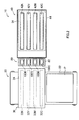
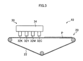
- Figure 1 to Figure 3 are a front view, plan view, and side view, respectively, of a main part configuration of an inkjet printing device in this embodiment.
- an inkjet printing device 10 which is a line printer of single-path system, mainly includes a paper sheet conveyance mechanism 20 (an example of recording means) for conveying a paper sheet (printer sheet) P as a recording medium, a head unit 30 (an example of recording means) for ejecting ink droplets of colors of cyan (C), magenta (M), yellow (Y), and black (K) toward the paper sheet P conveyed by the paper sheet conveyance mechanism 20, a maintenance unit 40 for maintaining each head mounted on the head unit 30, and a nozzle surface cleaning device 80 (inkjet head cleaning device) for cleaning a nozzle surface of each head mounded on the head unit 30.
- a paper sheet conveyance mechanism 20 an example of recording means
- a head unit 30 an example of recording means
- K black
- the paper sheet conveyance mechanism 20 which includes a belt conveyance mechanism, horizontally conveys the paper sheet P with the paper sheet P being suctioned to a belt 22 in traveling.
- the head unit 30 includes a head 32C ejecting ink droplets of cyan, a head 32M ejecting ink droplets of magenta, a head 32Y ejecting ink droplets of yellow, a head 32K ejecting ink droplets of black, a head support frame 34 having the heads 32C, 32M, 32Y, and 32K attached thereto, and a head support frame movement mechanism (not illustrated) for moving the head support frame 34.
- the heads (inkjet head) 32C, 32M, 32Y, and 32K each include a line head corresponding to a maximum paper width of the paper sheet P which is a printing object. Note the heads 32C, 32M, 32Y, and 32K have the same configuration, and thus, are referred to as the head 32 in the following description except when specifically distinguished.
- the head 32 (32C, 32M, 32Y, or 32K) is formed into a rectangular block shape and has a nozzle surface 33 (33C, 33M, 33Y, or 33K) formed on a bottom thereof.
- Figure 4 is a plan transparent view of the nozzle surface of the head.
- the nozzle surface 33 is formed into a rectangle shape and has nozzle rows formed thereon along its longitudinal direction.
- the head 32 in this embodiment includes a so-called matrix head in which nozzles N are arranged in a two-dimensional matrix.
- the matrix head can have a substantial distance narrowed between the nozzles N projected in the longitudinal direction of the head 32 to allow a density of the nozzles N to be increased.
- the head 32 in this embodiment ejects the ink droplets from the nozzle N by a so-called piezoelectric method.
- Each nozzle N is communicated with a pressure chamber and a wall face of the pressure chamber is vibrated by a piezo element to eject an ink droplet from the nozzle N.
- the ink ejection method is not limited to this and the head may be configured to use a thermal printing method for ejection.
- the head support frame 34 has a head attachment part (not illustrated) for attaching each head 32.
- Each head 32 is detachably attached to the head attachment part.
- Each head 32 attached to the head support frame 34 is arranged perpendicularly to a conveying direction of the paper sheet P.
- the heads are arranged in a certain order at a certain interval along the conveying direction of the paper sheet P (arranged in the order of cyan, magenta, yellow, and black in this example).
- the head attachment part is liftably provided to the head support frame 34 to be lifted and lowered by a lifting and lowering mechanism not illustrated in the figure.
- Each head 32 attached to the head attachment part is lifted and lowered perpendicularly to a conveying surface of the paper sheet P by the lifting and lowering mechanism.
- the head support frame movement mechanism slides the head support frame 34 horizontally in a direction perpendicular to the conveying direction of the paper sheet P at a position above the paper sheet conveyance mechanism 20.
- the head support frame movement mechanism includes, for example, a ceiling frame horizontally provided across the paper sheet conveyance mechanism 20, a guide rail laid on the ceiling frame, a traveling member slid and moved on the guide rail, and driving means moving the traveling member along the guide rail (e.g., feed screw mechanism).
- the head support frame 34 is attached to the traveling member to horizontally slide and move.
- the head support frame 34 is provided so as to be driven by the head support frame movement mechanism to be movable between a predetermined "image recording position (recording position)" and a “maintenance position (wet position)".
- the head support frame 34 in positioning at the image recording position, is located above the paper sheet conveyance mechanism 20. This allows printing with respect to the paper sheet P conveyed by the paper sheet conveyance mechanism 20.
- the head support frame 34 in positioning the maintenance position, is located at an arrangement position of the maintenance unit 40.
- the maintenance unit 40 includes caps 42 (42C, 42M, 42Y, and 42K) covering the nozzle surfaces 33 of each head 32.
- caps 42 42C, 42M, 42Y, and 42K covering the nozzle surfaces 33 of each head 32.
- the cap 42 includes a pressurizing and suctioning mechanism (not illustrated) for pressurizing and suctioning an inside of a nozzle, and a cleaning liquid supply mechanism (not illustrated) for supplying cleaning liquid inside the cap 42.
- a waste liquid tray 44 is arranged at a position below the cap 42. The cleaning liquid supplied to the cap 42 is discarded in the waste liquid tray 44 and is collected from the waste liquid tray 44 via a waste liquid collecting pipe 46 into a waste liquid tank 48.
- the nozzle surface cleaning device 80 is arranged between the paper sheet conveyance mechanism 20 and the maintenance unit 40.
- the nozzle surface cleaning device 80 wipes the nozzle surface 33 of the head 32 by a wiping web supplied with the cleaning liquid to clean the nozzle surface 33 when the head support frame 34 moves from the image recording position to the maintenance position.
- the nozzle surface cleaning device 80 includes wiping units 100C, 100M, 100Y, and 100K attached to a wiping device main body frame 82, and a wiping device main body lifting and lowering mechanism (not illustrated) for lifting and lowering the wiping device main body frame 82.
- the wiping units 100C, 100M, 100Y, and 100K allow a wiping web (reference numeral 112 in Figure 5 ) which is formed into a belt to travel while the wiping web being made to contact with the nozzle surface 33 of the head 32 for cleaning the nozzle surface 33.
- the wiping units 100C, 100M, 100Y, and 100K which are provided for the respective heads are arranged in the wiping device main body frame 82 so as to correspond to arrangement intervals of the head 32.
- the wiping units 100C, 100M, 100Y, and 100K have the same configuration, and thus, here, the wiping unit 100 is used as a representative thereof and a description is given of a configuration thereof.
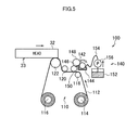
- FIG. 5 is a schematic view illustrating a general configuration of the wiping unit 100.
- the wiping unit 100 includes a conveying unit 110 conveying the wiping web 112, and a cleaning liquid supply unit 140 supplying the wiping web 112 with the cleaning liquid.
- the conveying unit 110 is configured to include a feed side web core 114 feeding the wiping web 112 before wiping, a take-up side web core 116 (an example of wiping member traveling means) which is rotatably driven by a take-up motor (reference numeral 210 in Figure 6 ) to wind the wiping web 112 after wiping, a first guide roll 118 which is brought into contact with the wiping web 112 fed from the feed side web core 114 to be rotated for guiding toward the cleaning liquid supply unit 140, a second guide roll 120 which is brought into contact with the wiping web 112 fed from the cleaning liquid supply unit 140 to be rotated for guiding toward a press roll 122, and the press roll 122 (an example of pressing means) bringing the wiping web 112 into contact with the nozzle surface 33 of the head 32 at a predetermined pressure.
- a feed side web core 114 feeding the wiping web 112 before wiping
- a take-up side web core 116 an example of wiping member traveling means
- the wiping web 112 (an example of wiping member of elongated shape) is formed of a sheet of knitted or woven microfiber of polyethylene terephthalate, polyethylene, nylon and the like, for example, and formed into a belt shape having a width corresponding to a width of the nozzle surface 33 of the head 32.
- the wiping web 112 is provided in a state of being wound around the feed side web core 114 into a rolled shape with the other tip end being fixed to the take-up side web core 116.
- the feed side web core 114 is mounted to be fitted into a feed shaft (not illustrated) which has one end thereof fixed to be horizontally supported.
- the feed shaft has a double tube structure in which an outer cylinder is supported rotatably around an inner cylinder.
- a reverse rotation prevention mechanism and a friction mechanism are arranged between the inner cylinder and the outer cylinder whereby the outer cylinder is configured to rotate in one direction only (feed direction of the wiping web 112) accompanied by a certain resistance.
- the take-up side web core 116 is mounted to be fitted into a take-up shaft (not illustrated) which is horizontally supported to be rotatable.
- the take-up shaft is coupled with the take-up motor whereby the take-up side web core 116 is driven by the take-up motor to rotate in one direction (take-up direction of the wiping web 112).
- the take-up shaft has a double structure in which an outer cylinder is supported rotatably around an inner cylinder.
- a torque limiter is arranged between the inner cylinder and the outer cylinder whereby the outer cylinder is configured to slide with respect to the inner cylinder when a load (torque) above a certain level is put. This can prevent an excessive tension from being exerted on the wiping web 112.
- the first guide roll 118 is supported to be rotatable by a shaft which is horizontally provided (not illustrated) to guide the wiping web 112 fed from the feed side web core 114 toward the cleaning liquid supply unit 140.
- the second guide roll 120 is supported to be rotatable by a shaft which is horizontally provided (not illustrated) to guide the wiping web 112 fed from the cleaning liquid supply unit 140 toward the press roll 122.
- the press roll 122 is horizontally provided with one end of a portion of the shaft thereof supported to be rotatable.
- the press roll 122 is formed of a rubber roll having a width corresponding to that of the wiping web 112 to bring the wiping web 112 into contact with the nozzle surface 33 of the head 32 at a predetermined pressure.
- the wiping web 112 is provided in a state of being wound around the feed side web core 114 into a rolled shape, and thus, undergoes mounting to (replacement with) the wiping unit 100 in this state also.
- the feed side web core 114 is mounted to be fitted into the feed shaft, followed by wrapping the web on the first guide roll 118, the second guide roll 120, and the press roll 122 in this order and fitting the take-up side web core 116 into the take-up shaft to complete the mounting.
- the cleaning liquid supply unit 140 (an example of cleaning liquid supply means) is configured to include an anilox roll 142, a cleaning liquid tray 144 where a part of the anilox roll 142 is immersed in the cleaning liquid reserved, a doctor blade 146 brought into contact with the anilox roll 142 to remove the cleaning liquid excess on the surface thereof, an intermediate roll 148 brought into contact with the anilox roll 142 to be rotated, a transfer roll 150 brought into contact with the intermediate roll 148 to be rotated, a cleaning liquid tank 152 in which the cleaning liquid is reserved, a cleaning liquid pipe 154 linking the cleaning liquid tank 152 to the cleaning liquid tray 144, and a cleaning liquid pump 156 sending the cleaning liquid from the cleaning liquid tray 144 to the cleaning liquid tray 144.
- the anilox roll 142 which is a roll having many cells formed on a surface thereof for retaining the cleaning liquid, has a width corresponding to that of the wiping web 112.
- the anilox roll 142 is configured to be rotatable in a predetermined direction (clockwise direction in the example of Figure 5 ) by a drive motor (reference numeral 214 in Figure 6 ).
- the cleaning liquid tray 144 reserves the cleaning liquid. A part of the anilox roll 142 is immersed in the cleaning liquid in the cleaning liquid tray 144.
- the doctor blade 146 which is a metal thin plate having a width corresponding to that of the anilox roll 142, is held with one end thereof being biased to be pressed to a cylindrical periphery of the anilox roll 142.
- the intermediate roll 148 which is a roll having a width corresponding to that of the anilox roll 142, is brought into contact with the anilox roll 142 to be rotated in conjunction with the anilox roll 142.
- the cleaning liquid retained on the surface of the anilox roll 142 is transferred to the intermediate roll 148.
- the transfer roll 150 which is a roll having a width corresponding to that of the intermediate roll 148, is brought into contact with the intermediate roll 148 to be rotated in conjunction with the intermediate roll 148. Therefore, the cleaning liquid retained on the surface of the intermediate roll 148 is transferred to the surface of the transfer roll 150.
- the transfer roll 150 is in contact with the wiping web 112 to be rotated in the same direction as the conveying direction of the wiping web 112. Therefore, the cleaning liquid transferred from the surface of the intermediate roll 148 to the surface of the transfer roll 150 is supplied to the wiping web 112. This makes the cleaning liquid absorbed into the wiping web 112.
- the cleaning liquid tray 144 is coupled via the cleaning liquid pipe 154 to the cleaning liquid tank 152.
- the cleaning liquid pump 156 which is provided in the middle way of the cleaning liquid pipe 154, sends the cleaning liquid reserved in the cleaning liquid tank 152 to the cleaning liquid tray 144.
- the cleaning liquid tank 152 and the cleaning liquid pump 156 are configured to be provided for one wiping unit 100, but one cleaning liquid tank and one cleaning liquid pump may be configured to be used in common by the wiping units 100C, 100M, 100Y, and 100K.
- the cleaning liquid sent by one cleaning liquid pump is supplied to the cleaning liquid trays 144C, 144M, 144Y, and 144K of the wiping units 100C, 100M, 100Y, and 100K, respectively, and used by the respective anilox rolls 142C, 142M, 142Y, and 142K.
- the configuration for supplying the cleaning liquid to the wiping web 112 is not limited to the example illustrated in Figure 5 , but any configuration may be employed so long as the wiping web 112 is supplied with the cleaning liquid in a certain amount.
- FIG. 6 is a block diagram illustrating an electrical configuration of the nozzle surface cleaning device 80.
- the nozzle surface cleaning device 80 includes a maintenance controller 200, storage 202, head support frame controller 204, head support frame movement mechanism 206, web controller 208, take-up motor 210, anilox roll controller 212, drive motor 214, wiping device main body lifting and lowering mechanism 216.
- the maintenance controller 200 (an example of control means) controls a wiping timing for the head 32 and generally controls the nozzle surface cleaning device 80.
- the storage 202 stores therein various parameters necessary for the maintenance controller 200.
- the head support frame controller 204 controls the head support frame movement mechanism 206 in accordance with an instruction from the maintenance controller 200 to control a movement speed of the head 32.
- the web controller 208 controls the take-up motor 210 in accordance with an instruction from the maintenance controller 200 to control a take-up speed of the take-up side web core 116. This controls a traveling speed of the wiping web 112.
- the anilox roll controller 212 controls the drive motor 214 in accordance with an instruction from the maintenance controller 200 to control a rotation speed of the anilox roll 142. This controls an amount of the cleaning liquid supplied from the anilox roll 142 to wiping web 112.
- the nozzle surface cleaning device 80 is configured to be generally liftable by the wiping device main body lifting and lowering mechanism 216.
- the maintenance controller 200 controls the wiping device main body lifting and lowering mechanism 216 to lift and lower a main body of the nozzle surface cleaning device 80.
- Operation of the nozzle surface cleaning device 80 is controlled by the maintenance controller 200.
- the maintenance controller 200 wipes and cleans the nozzle surface 33 by the wiping unit 100 in the course of moving the head 32 from the image recording position to the maintenance position.
- the maintenance controller 200 controls the wiping device main body lifting and lowering mechanism 216 such that the nozzle surface cleaning device 80 is made to stand by at a predetermined standby position other than during cleaning and to lift during cleaning to a predetermined operation position which is a position lifted from the standby position by a predetermined amount.
- each wiping unit 100 can wipe the nozzle surface 33 of each head 32.
- the wiping web 112 wrapped on the press roll 122 can be pressed to and brought into contact with the nozzle surface 33 of the head 32.
- the maintenance controller 200 controls the head support frame controller 204 to control the head support frame movement mechanism such that the head 32 is moved to the maintenance position.
- the maintenance controller 200 controls conveyance of the wiping web 112 by the conveying unit 110 correspondingly to a timing when each head 32 reaches the wiping unit 100. In other words, driving of the take-up motor 210 is started. This allows the wiping web 112 to be fed out from the feed side web core 114, travel, and be taken up by the take-up side web core 116.
- the feed shaft of the feed side web core 114 is given a friction by the friction mechanism, while the take-up shaft of the take-up side web core 116 slides on receiving a load of a certain level put by the torque limiter, such that the wiping web 112 can be given a certain tension to travel.
- the maintenance controller 200 controls the cleaning liquid supply unit 140 at the same time as the wiping web 112 traveling to make the wiping web 112 wetted by the cleaning liquid. In other words, the anilox roll controller 212 starts controlling.
- the cleaning liquid reserved in the cleaning liquid tank 152 is sent to the cleaning liquid tray 144 of the cleaning liquid supply unit 140 by the cleaning liquid pump 156.
- the anilox roll 142 a part of which is immersed in the cleaning liquid reserved in the cleaning liquid tray 144, retains the cleaning liquid in the cells on the surface thereof immersed.
- the anilox roll 142 in conjunction with rotating by the drive motor 214, draws the cleaning liquid retained in the cells thereof from the cleaning liquid tray 144.
- the cells on the surface newly immersed in the cleaning liquid are filled with the cleaning liquid.
- the doctor blade 146 is brought into contact with the rotating anilox roll 142 such that the cleaning liquid excess on the surface of the anilox roll 142 is removed while the cleaning liquid is retained in the cells.
- the cleaning liquid is measured by the anilox roll 142 and the doctor blade 146.
- the measured cleaning liquid is transferred to the intermediate roll 148.
- the cleaning liquid transferred to the intermediate roll 148 is again transferred to the transfer roll 150 which is brought into contact with the intermediate roll 148 to be rotated.
- the transfer roll 150 brought into contact with the wiping web 112 to be rotated at the same speed as the traveling speed of the wiping web 112 transfers and supplies the cleaning liquid transferred from the intermediate roll 148 to the wiping web 112.
- the cleaning liquid measured by the anilox roll 142 and the doctor blade 146 is supplied to the wiping web 112 in a certain amount.
- the cleaning liquid amount for the wiping web 112 can be adjusted by controlling the rotation speed of the anilox roll 142. For example, if the rotation speed of the anilox roll 142 is raised, the rotation speed of the transfer roll 150 becomes faster than the traveling speed of the wiping web 112 and slip occurs between the surface of the transfer roll 150 and the surface of the wiping web 112 to increase the cleaning liquid amount supplied to the wiping web 112.
- the cleaning liquid is supplied in an amount which gets the wiping web 112 into a saturated condition.
- the saturated condition is a condition where the wiping web 112 is maximally impregnated with the cleaning liquid.
- the wiping web 112 supplied with the cleaning liquid in a certain amount is guided toward the press roll 122 by the second guide roll 120 to be pressed to and brought into contact with the nozzle surface 33 at the press roll 122 due to traveling driven by the take-up motor 210.
- the head 32 moves by the head support frame movement mechanism 206. This makes the press roll 122 on which the wiping web 112 is wrapped slide in a state of being pressed to and brought into contact with the nozzle surface 33 to wipe and clean the nozzle surface 33.
- the wiping web 112 travels in a direction opposite to a moving direction of the nozzle surface 33 to wipe the nozzle surface 33. This makes it possible to efficiently wipe the nozzle surface 33. Additionally, a new surface (unused area) of the wiping web 112 can be always used to wipe the nozzle surface 33.
- the wiping web 112 after wiping the nozzle surface 33 is taken up by the take-up side web core 116.
- the head 32 is moved by the head support frame movement mechanism 206 to the maintenance position and the nozzle surface 33 is covered by the cap 42.
- the wiping unit 100 configured in this way, an ink mist adhered to the nozzle surface 33 and the cleaning liquid supplied to the wiping web 112 are mixed at a contacting portion between the nozzle surface 33 and the wiping web 112.
- the liquid in which the ink and the cleaning liquid are mixed at the contacting portion is referred to as the mixed liquid.
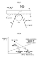
- Figure 7 is an illustration for explaining a mixing ratio for the mixed liquid.
- Figure 8 is a graph illustrating a relationship between mixed liquid properties (physical properties) and presence or absence of remaining liquid on the nozzle surface 33 during wiping and cleaning.
- a graph having an abscissa axis of surface tension [mN/m] of the mixed liquid and an ordinate axis of viscosity [mP ⁇ s] of the mixed liquid is illustrated and the presence or absence of remaining liquid is illustrated on the graph.
- a relationship between surface tension and viscosity of the mixed liquid in a case where a certain ink and a certain cleaning liquid are used varies depending on the mixing ratio R thereof on a line connecting a plotted point at a surface tension and viscosity of the ink of 100% and a plotted point at a surface tension and viscosity of the cleaning liquid of 100%.
- the mixing ratio R of the mixed liquid is decreased from the ink of 100% (that is, a ratio of the inflow amount of the cleaning liquid is made larger), the remaining liquid on the nozzle surface 33 after wiping by the wiping web 112 disappears at a certain mixing ratio.
- a border line between the presence and absence of remaining liquid varies depending on liquid repellent performance of the nozzle surface 33.
- the mixing ratio R of the mixed liquid can be adjusted by controlling the movement speed Vbar of the head 32, the ink mist amount M of the nozzle surface 33, the conveyance speed Vweb of the wiping web 112, and the water-holding amount L of the wiping web.
- y f(x)
- the nozzle surface 33 may be wiped and cleaned by controlling at least one of the movement speed Vbar of the head 32, the ink mist amount M of the nozzle surface 33, the conveyance speed Vweb of the wiping web 112, and the water-holding amount L of the wiping web such that a state of the mixed liquid is put into a state satisfying the relationship of y ⁇ f(x).
- the movement speed Vbar of the head 32 can be controlled by adjusting the movement speed of the head support frame by the head support frame controller 204.
- the head support frame 34 since the head support frame 34 has the heads 32C, 32M, 32Y, and 32K of the respective colors attached thereto, the movement speeds for the respective heads cannot be separately controlled, but another aspect may also be employed in which the head support frame 34 and the head support frame movement mechanism 206 are provided for each head to control the movement speed for each head.
- the ink mist amount M of the nozzle surface 33 can be controlled by changing maintenance frequency (time elapsed from the previous maintenance, and the number of printed sheets).
- the ink mist amount M of the nozzle surface 33 refers to a value assuming the dirtiest state depending on the time elapsed from the previous maintenance, and the number of printed sheets.
- the ink mist amount M of the nozzle surface 33 can be found by imaging the nozzle surface 33 by an image pickup device.
- another aspect of configuration may also be employed in which fixed values are given to Vbar, Vweb, and L, and when the ink mist amount M exceeds the predetermined value, the maintenance is performed.
- the conveyance speed Vweb of the wiping web 112 can be controlled by adjusting the take-up speed of the take-up motor 210 by the web controller 208. Further, the water-holding amount L of the wiping web 112 can be controlled by adjusting the rotation speed of the drive motor 214 (rotation speed of the anilox roll 142) by the anilox roll controller 212.
- the cleaning liquid is supplied in an amount which gets the wiping web 112 into a saturated condition such that the water-holding amount is constant.
- the water-holding amount may be adjusted by changing a thickness or material of the wiping web 112 to supply the cleaning liquid in an amount getting the wiping web 112 into the saturated condition.
- the maintenance controller 200 calculates the mixing ratio of the mixed liquid satisfying the condition of y ⁇ f(x) on the basis of the relationship between the ink and cleaning liquid to be used, and controls the wiping unit 100 so as to satisfy the calculated mixing ratio.
- Such controlling can prevent increase of the number of the maintenances beyond necessity, excessive use of the cleaning liquid caused by supplying the cleaning liquid beyond necessity, excessive use of the wiping web 112 caused by speeding up the conveyance of the wiping web 112 beyond necessity, and increase of the maintenance time period caused by slowing down the movement speed of the head beyond necessity.
- a configuration may be employed in which various control parameters for Vbar, M, Vweb, and L are input via an input part (not illustrated) such that the state of the mixed liquid is put into a state satisfying the relationship of y ⁇ f(x).
- Figure 9 is a graph illustrating a found border line between the presence and absence of remaining liquid which is plotted using a circle in a case of the liquid remaining and a cross in a case of no remaining liquid regarding mixed liquids, for the nozzle surface 33 having a certain liquid repellent performance.
- the border line between the presence and absence of remaining liquid can be expressed as below.
- no remaining liquid on the nozzle surface 33 after wiping and cleaning can be achieved by controlling at least one of Vbar, M, Vweb, and L such that the state of the mixed liquid is put into a state satisfying the relationship of y ⁇ f(x).
- the mixed liquid is connected with meniscus of the nozzle, the mixed liquid remaining on the nozzle surface is dried and gets into the nozzle in wiping next time, a long time contact between the nozzle surface and the mixed liquid causes a liquid repellent film of the nozzle surface to deteriorate, and the like. Therefore, the printing accuracy by way of the head 32 can be stabilized.
- 10 inkjet printing device, 20 ... paper sheet conveyance mechanism, 30 ... head unit, 32 (32C, 32M, 32Y, and 32K) ... head, 33 ... nozzle surface, 80 ... nozzle surface cleaning device, 100 (100C, 100M, 100Y, and 100K) ... wiping unit, 112 ... wiping web, 116 ... take-up side web core, 122 ... press roll, 142 ... anilox roll, 200 ... maintenance controller, 202 ... storage, 204 ... head support frame controller, 208 ... web controller, 210 ... take-up motor, 212 ... anilox roll controller, 214 ... drive motor, 216 ... wiping device main body lifting and lowering mechanism
Landscapes
- Ink Jet (AREA)
Abstract
Description
- The present invention relates to an inkjet head cleaning device and cleaning method, and an inkjet printing device, and particularly relates to head cleaning technology for wiping a nozzle surface of an inkjet head using a wiping member supplied with cleaning liquid.
- A dirty nozzle surface (surface where a nozzle is formed) of a head in an inkjet printing device causes ejection failure. For this reason, the nozzle surface is periodically cleaned.
- As a method for cleaning the nozzle surface, there have been known in the past a cleaning method of wiping the nozzle surface by a blade, a cleaning method of wiping the nozzle surface by a web, and the like.
- PTL 1 discloses a head maintenance device including a drop nozzle dropping cleaning liquid that is an ink solvent onto a cleaning cloth, in which the cleaning cloth in a state of being wetted with the ink solvent is conveyed to a cleaning position to absorb and remove the ink droplet on the nozzle surface.
- According to the technology in PTL 1, even if the ink droplet deposited on the nozzle surface becomes thickened due to a dry atmosphere or the like, a concentration difference between the cleaning liquid seeping into the cleaning cloth and the thickened ink droplet generates an osmotic pressure action such that the ink droplet deposited on the nozzle surface is effectively absorbed and removed.
- However, in the technology in PTL 1, a mixed liquid of the ink and the cleaning liquid remains on the head nozzle surface after cleaning in some cases. If the mixed liquid remains on the head nozzle surface, problems may occur, for example, the mixed liquid is connected with meniscus of the nozzle, the mixed liquid remaining on the nozzle surface is dried and gets into the nozzle in wiping next time, a long time contact between the nozzle surface and the mixed liquid causes a liquid repellent film of the nozzle surface to deteriorate, and the like.
- Therefore, in order to prevent the mixed liquid from remaining on the nozzle surface, physical properties of the mixed liquid need to be considered.
- On the other hand,
PTL 2 discloses a technology in which a surface is cleaned by supplying head liquid to a surface of an inkjet head and performing wiping operation such that relationship among surface tension of the surface of the inkjet head, surface tension of an ink, and surface tension of the head liquid satisfies a predetermined condition, and thereby, surface tension of an ink residue mixed liquid with respect to a deposited surface is made higher than that of the ink residue only, and materials of a wiper blade are selected in terms of the ink residue mixed liquid. - According to the technology in
PTL 2, the mixed liquid can be easily removed from the nozzle surface. -
- {PTL 1}
Japanese Patent Application Laid-Open No.2010-274533 - {PTL 2}
Japanese Patent Application Laid-Open No.2006-205714 - However, the present application inventor has found as a result of earnest study that it is not enough to specify the surface tension of the mixed liquid in order to clean the nozzle surface with no remaining liquid.
- The present invention has been made in consideration of such a circumstance, and has an object to provide an inkjet head cleaning device and cleaning method, and an inkjet printing device in which a nozzle surface can be cleaned with no remaining liquid by controlling physical properties of mixed liquid.
- In order to achieve the above object, an aspect of an inkjet head cleaning device is an inkjet head cleaning device for an inkjet head having a nozzle surface on which nozzles configured to eject ink are arranged, including wiping member traveling means allowing a wiping member of elongated shape having absorbency to travel along a conveying path in a longitudinal direction, cleaning liquid supply means configured to supply a cleaning liquid to the wiping member, pressing means configured to press and bring the wiping member supplied with the cleaning liquid to and into contact with the nozzle surface, and sliding means configured to slide the pressing means along the nozzle surface, in which the nozzle surface is cleaned by way of putting a state of a mixed liquid of the ink and the cleaning liquid at a contacting portion between the wiping member and the nozzle surface into a state satisfying a predetermined relationship represented by a relationship between a surface tension and viscosity of the mixed liquid.
- According to the aspect, a state of the mixed liquid of the ink adhered to the nozzle surface and the cleaning liquid supplied to the wiping member is put into a state satisfying a predetermined relationship represented on the basis of the relationship between the surface tension and the viscosity, wiping and cleaning the nozzle surface with no remaining liquid.
- It is preferable to control at least one of a traveling speed of the wiping member traveling means, a cleaning liquid amount supplied by the cleaning liquid supply means, a sliding speed of the sliding means, and a cleaning frequency of the inkjet head to put the state of the mixed liquid into the state satisfying the predetermined relationship. This allows the state of the mixed liquid to be appropriately put into the state satisfying a predetermined relationship.
- It is preferable that the predetermined relationship is defined for each liquid repellent performance of the nozzle surface. This allows the nozzle surface to be wiped and cleaned with no remaining liquid in a case where the liquid repellent performance of the nozzle surface is varied.
- It is preferable that the predetermined relationship is a relationship calculated by experimentally finding presence or absence of residue on the nozzle surface upon cleaning the nozzle surface regarding a plurality of mixed liquids different in the surface tension and the viscosity. This can appropriately define the relationship of mixed liquids.
- It is preferable that, in a graph plotting a result obtained from the presence or absence of the residue regarding the plurality of mixed liquids with an abscissa axis of surface tensions of various mixed liquids and an ordinate axis of viscosities of the mixed liquid, assuming a border line between the presence and absence of the residue calculated from the plotted graph, the predetermined relationship is a relationship satisfying an area on a no-residue side of the border line. This allows the nozzle surface to be wiped and cleaned with no remaining liquid.
- It is preferable that the cleaning liquid supply means supplies the cleaning liquid in an amount which gets the absorbency of the wiping member into a saturated condition. This enables a stable wiping and cleaning.
- It is preferable that the control means controls the cleaning frequency of the inkjet head assuming a state where the ink maximally adheres to the nozzle surface. This allows the nozzle surface to be appropriately wiped and cleaned.
- In order to achieve the above object, an aspect of an inkjet printing device is an inkjet printing device, including an inkjet head having a nozzle surface on which nozzles for ejecting ink are arranged, recording means relatively moving the inkjet head and a recording medium while ejecting the ink from the nozzle for recording on recording medium, and the inkjet head cleaning device described above.
- According the aspect, even in a case where the ink adheres to the nozzle surface when the ink is ejected from the nozzle for recording on the recording medium, a state of the mixed liquid of the ink adhered to the nozzle surface and the cleaning liquid supplied to the wiping member is put into a state satisfying a predetermined relationship represented on the basis of the relationship between the surface tension and the viscosity, wiping and cleaning the nozzle surface with no remaining liquid.
- It is preferable that the inkjet head further including wetting means configured to wet the nozzle, and moving means configured to move the inkjet head between a recording position for recording on the recording medium by the recording means and a wet position for wetting the nozzle by the wetting means, in which the inkjet head cleaning device is arranged between the recording position and the wet position. This allows the nozzle surface to be wiped and cleaned upon moving the inkjet head from the recording position to the wet position.
- In order to achieve the above object, an aspect of an inkjet head cleaning method is a cleaning method of an inkjet head having a nozzle surface on which nozzles configured to eject ink are arranged, including a wiping member traveling step of allowing a wiping member of elongated shape having absorbency to travel along a conveying path in a longitudinal direction, a cleaning liquid supply step of supplying a cleaning liquid to the wiping member, a pressing step of pressing and bringing the wiping member supplied with the cleaning liquid to and into contact with the nozzle surface, and a sliding step of sliding the pressing means along the nozzle surface, in which the nozzle surface is cleaned by way of putting a state of a mixed liquid of the ink and the cleaning liquid at a contacting portion between the wiping member and the nozzle surface into a state satisfying a predetermined relationship represented on the basis of a relationship between a surface tension and viscosity of the mixed liquid.
- According to the aspect, a state of the mixed liquid of the ink adhered to the nozzle surface and the cleaning liquid supplied to the wiping member is put into a state satisfying a predetermined relationship represented on the basis of the relationship between the surface tension and the viscosity, therefore, it is possible to clean the nozzle surface with no remaining liquid.
- According to the invention, the nozzle surface on which the ink is deposited can be cleaned with no remaining liquid by use of the wiping member supplied with the cleaning liquid. This can stabilize printing accuracy by way of the inkjet head.
-
- {
Figure 1} Figure 1 is a front view illustrating a main part configuration of an inkjet printing device. - {
Figure 2} Figure 2 is a plan view illustrating the main part configuration of the inkjet printing device. - {
Figure 3} Figure 3 is a side view illustrating the main part configuration of the inkjet printing device. - {
Figure 4} Figure 4 is a plan transparent view of a nozzle surface of a head. - {
Figure 5} Figure 5 is a schematic view illustrating a general configuration of a wiping unit. - {
Figure 6} Figure 6 is a block diagram illustrating an electrical configuration of a nozzle surface cleaning device. - {
Figure 7} Figure 7 is an illustration for explaining a mixing ratio for mixed liquid. - {
Figure 8} Figure 8 is a graph illustrating a relationship between mixed liquid properties and presence or absence of remaining liquid on the nozzle surface. - {
Figure 9} Figure 9 is a graph illustrating a found border line between presence and absence of the remaining liquid. - Hereinafter, a description is given in detail of preferred embodiments of the invention with reference to the drawings.
-
Figure 1 to Figure 3 are a front view, plan view, and side view, respectively, of a main part configuration of an inkjet printing device in this embodiment. - As illustrated in the figures, an
inkjet printing device 10, which is a line printer of single-path system, mainly includes a paper sheet conveyance mechanism 20 (an example of recording means) for conveying a paper sheet (printer sheet) P as a recording medium, a head unit 30 (an example of recording means) for ejecting ink droplets of colors of cyan (C), magenta (M), yellow (Y), and black (K) toward the paper sheet P conveyed by the papersheet conveyance mechanism 20, amaintenance unit 40 for maintaining each head mounted on thehead unit 30, and a nozzle surface cleaning device 80 (inkjet head cleaning device) for cleaning a nozzle surface of each head mounded on thehead unit 30. - The paper
sheet conveyance mechanism 20, which includes a belt conveyance mechanism, horizontally conveys the paper sheet P with the paper sheet P being suctioned to abelt 22 in traveling. - The
head unit 30 includes ahead 32C ejecting ink droplets of cyan, ahead 32M ejecting ink droplets of magenta, ahead 32Y ejecting ink droplets of yellow, ahead 32K ejecting ink droplets of black, ahead support frame 34 having theheads head support frame 34. - The heads (inkjet head) 32C, 32M, 32Y, and 32K each include a line head corresponding to a maximum paper width of the paper sheet P which is a printing object. Note the
heads head 32 in the following description except when specifically distinguished. - The head 32 (32C, 32M, 32Y, or 32K) is formed into a rectangular block shape and has a nozzle surface 33 (33C, 33M, 33Y, or 33K) formed on a bottom thereof.
-
Figure 4 is a plan transparent view of the nozzle surface of the head. - The
nozzle surface 33 is formed into a rectangle shape and has nozzle rows formed thereon along its longitudinal direction. Thehead 32 in this embodiment includes a so-called matrix head in which nozzles N are arranged in a two-dimensional matrix. The matrix head can have a substantial distance narrowed between the nozzles N projected in the longitudinal direction of thehead 32 to allow a density of the nozzles N to be increased. - The
head 32 in this embodiment ejects the ink droplets from the nozzle N by a so-called piezoelectric method. Each nozzle N is communicated with a pressure chamber and a wall face of the pressure chamber is vibrated by a piezo element to eject an ink droplet from the nozzle N. The ink ejection method is not limited to this and the head may be configured to use a thermal printing method for ejection. - The
head support frame 34 has a head attachment part (not illustrated) for attaching eachhead 32. Eachhead 32 is detachably attached to the head attachment part. - Each
head 32 attached to thehead support frame 34 is arranged perpendicularly to a conveying direction of the paper sheet P. The heads are arranged in a certain order at a certain interval along the conveying direction of the paper sheet P (arranged in the order of cyan, magenta, yellow, and black in this example). - The head attachment part is liftably provided to the
head support frame 34 to be lifted and lowered by a lifting and lowering mechanism not illustrated in the figure. Eachhead 32 attached to the head attachment part is lifted and lowered perpendicularly to a conveying surface of the paper sheet P by the lifting and lowering mechanism. - The head support frame movement mechanism slides the
head support frame 34 horizontally in a direction perpendicular to the conveying direction of the paper sheet P at a position above the papersheet conveyance mechanism 20. - The head support frame movement mechanism includes, for example, a ceiling frame horizontally provided across the paper
sheet conveyance mechanism 20, a guide rail laid on the ceiling frame, a traveling member slid and moved on the guide rail, and driving means moving the traveling member along the guide rail (e.g., feed screw mechanism). Thehead support frame 34 is attached to the traveling member to horizontally slide and move. - The
head support frame 34 is provided so as to be driven by the head support frame movement mechanism to be movable between a predetermined "image recording position (recording position)" and a "maintenance position (wet position)". - The
head support frame 34, in positioning at the image recording position, is located above the papersheet conveyance mechanism 20. This allows printing with respect to the paper sheet P conveyed by the papersheet conveyance mechanism 20. - On the other hand, the
head support frame 34, in positioning the maintenance position, is located at an arrangement position of themaintenance unit 40. - The
maintenance unit 40 includes caps 42 (42C, 42M, 42Y, and 42K) covering the nozzle surfaces 33 of eachhead 32. When the apparatus is stopped for a long time or the like, thehead 32 is moved to the arrangement position (maintenance position) of themaintenance unit 40 to cover thenozzle surface 33 by the cap 42. This prevents non-ejection caused by dryness. - The cap 42 includes a pressurizing and suctioning mechanism (not illustrated) for pressurizing and suctioning an inside of a nozzle, and a cleaning liquid supply mechanism (not illustrated) for supplying cleaning liquid inside the cap 42. A
waste liquid tray 44 is arranged at a position below the cap 42. The cleaning liquid supplied to the cap 42 is discarded in thewaste liquid tray 44 and is collected from thewaste liquid tray 44 via a wasteliquid collecting pipe 46 into awaste liquid tank 48. - The nozzle
surface cleaning device 80 is arranged between the papersheet conveyance mechanism 20 and themaintenance unit 40. The nozzlesurface cleaning device 80 wipes thenozzle surface 33 of thehead 32 by a wiping web supplied with the cleaning liquid to clean thenozzle surface 33 when thehead support frame 34 moves from the image recording position to the maintenance position. - The nozzle
surface cleaning device 80 includes wipingunits main body frame 82, and a wiping device main body lifting and lowering mechanism (not illustrated) for lifting and lowering the wiping devicemain body frame 82. - The wiping
units reference numeral 112 inFigure 5 ) which is formed into a belt to travel while the wiping web being made to contact with thenozzle surface 33 of thehead 32 for cleaning thenozzle surface 33. The wipingunits main body frame 82 so as to correspond to arrangement intervals of thehead 32. The wipingunits wiping unit 100 is used as a representative thereof and a description is given of a configuration thereof. -
Figure 5 is a schematic view illustrating a general configuration of thewiping unit 100. As illustrated in the figure, thewiping unit 100 includes a conveyingunit 110 conveying the wipingweb 112, and a cleaningliquid supply unit 140 supplying the wipingweb 112 with the cleaning liquid. - The conveying
unit 110 is configured to include a feedside web core 114 feeding the wipingweb 112 before wiping, a take-up side web core 116 (an example of wiping member traveling means) which is rotatably driven by a take-up motor (reference numeral 210 inFigure 6 ) to wind the wipingweb 112 after wiping, afirst guide roll 118 which is brought into contact with the wipingweb 112 fed from the feedside web core 114 to be rotated for guiding toward the cleaningliquid supply unit 140, asecond guide roll 120 which is brought into contact with the wipingweb 112 fed from the cleaningliquid supply unit 140 to be rotated for guiding toward apress roll 122, and the press roll 122 (an example of pressing means) bringing the wipingweb 112 into contact with thenozzle surface 33 of thehead 32 at a predetermined pressure. - The wiping web 112 (an example of wiping member of elongated shape) is formed of a sheet of knitted or woven microfiber of polyethylene terephthalate, polyethylene, nylon and the like, for example, and formed into a belt shape having a width corresponding to a width of the
nozzle surface 33 of thehead 32. The wipingweb 112 is provided in a state of being wound around the feedside web core 114 into a rolled shape with the other tip end being fixed to the take-upside web core 116. - The feed
side web core 114 is mounted to be fitted into a feed shaft (not illustrated) which has one end thereof fixed to be horizontally supported. The feed shaft has a double tube structure in which an outer cylinder is supported rotatably around an inner cylinder. A reverse rotation prevention mechanism and a friction mechanism are arranged between the inner cylinder and the outer cylinder whereby the outer cylinder is configured to rotate in one direction only (feed direction of the wiping web 112) accompanied by a certain resistance. - The take-up
side web core 116 is mounted to be fitted into a take-up shaft (not illustrated) which is horizontally supported to be rotatable. The take-up shaft is coupled with the take-up motor whereby the take-upside web core 116 is driven by the take-up motor to rotate in one direction (take-up direction of the wiping web 112). - The take-up shaft has a double structure in which an outer cylinder is supported rotatably around an inner cylinder. A torque limiter is arranged between the inner cylinder and the outer cylinder whereby the outer cylinder is configured to slide with respect to the inner cylinder when a load (torque) above a certain level is put. This can prevent an excessive tension from being exerted on the wiping
web 112. - The
first guide roll 118 is supported to be rotatable by a shaft which is horizontally provided (not illustrated) to guide the wipingweb 112 fed from the feedside web core 114 toward the cleaningliquid supply unit 140. - The
second guide roll 120 is supported to be rotatable by a shaft which is horizontally provided (not illustrated) to guide the wipingweb 112 fed from the cleaningliquid supply unit 140 toward thepress roll 122. - The
press roll 122 is horizontally provided with one end of a portion of the shaft thereof supported to be rotatable. Thepress roll 122 is formed of a rubber roll having a width corresponding to that of the wipingweb 112 to bring the wipingweb 112 into contact with thenozzle surface 33 of thehead 32 at a predetermined pressure. - Here, as described above, the wiping
web 112 is provided in a state of being wound around the feedside web core 114 into a rolled shape, and thus, undergoes mounting to (replacement with) thewiping unit 100 in this state also. Specifically, the feedside web core 114 is mounted to be fitted into the feed shaft, followed by wrapping the web on thefirst guide roll 118, thesecond guide roll 120, and thepress roll 122 in this order and fitting the take-upside web core 116 into the take-up shaft to complete the mounting. - The cleaning liquid supply unit 140 (an example of cleaning liquid supply means) is configured to include an
anilox roll 142, a cleaningliquid tray 144 where a part of theanilox roll 142 is immersed in the cleaning liquid reserved, adoctor blade 146 brought into contact with theanilox roll 142 to remove the cleaning liquid excess on the surface thereof, anintermediate roll 148 brought into contact with theanilox roll 142 to be rotated, atransfer roll 150 brought into contact with theintermediate roll 148 to be rotated, a cleaningliquid tank 152 in which the cleaning liquid is reserved, a cleaningliquid pipe 154 linking the cleaningliquid tank 152 to the cleaningliquid tray 144, and a cleaningliquid pump 156 sending the cleaning liquid from the cleaningliquid tray 144 to the cleaningliquid tray 144. - The
anilox roll 142, which is a roll having many cells formed on a surface thereof for retaining the cleaning liquid, has a width corresponding to that of the wipingweb 112. Theanilox roll 142 is configured to be rotatable in a predetermined direction (clockwise direction in the example ofFigure 5 ) by a drive motor (reference numeral 214 inFigure 6 ). - The cleaning
liquid tray 144 reserves the cleaning liquid. A part of theanilox roll 142 is immersed in the cleaning liquid in the cleaningliquid tray 144. - The
doctor blade 146, which is a metal thin plate having a width corresponding to that of theanilox roll 142, is held with one end thereof being biased to be pressed to a cylindrical periphery of theanilox roll 142. - The
intermediate roll 148, which is a roll having a width corresponding to that of theanilox roll 142, is brought into contact with theanilox roll 142 to be rotated in conjunction with theanilox roll 142. The cleaning liquid retained on the surface of theanilox roll 142 is transferred to theintermediate roll 148. - The
transfer roll 150, which is a roll having a width corresponding to that of theintermediate roll 148, is brought into contact with theintermediate roll 148 to be rotated in conjunction with theintermediate roll 148. Therefore, the cleaning liquid retained on the surface of theintermediate roll 148 is transferred to the surface of thetransfer roll 150. - At this time, the
transfer roll 150 is in contact with the wipingweb 112 to be rotated in the same direction as the conveying direction of the wipingweb 112. Therefore, the cleaning liquid transferred from the surface of theintermediate roll 148 to the surface of thetransfer roll 150 is supplied to the wipingweb 112. This makes the cleaning liquid absorbed into the wipingweb 112. - The cleaning
liquid tray 144 is coupled via the cleaningliquid pipe 154 to the cleaningliquid tank 152. The cleaningliquid pump 156, which is provided in the middle way of the cleaningliquid pipe 154, sends the cleaning liquid reserved in the cleaningliquid tank 152 to the cleaningliquid tray 144. - Here, the cleaning
liquid tank 152 and the cleaningliquid pump 156 are configured to be provided for onewiping unit 100, but one cleaning liquid tank and one cleaning liquid pump may be configured to be used in common by the wipingunits units - The configuration for supplying the cleaning liquid to the wiping
web 112 is not limited to the example illustrated inFigure 5 , but any configuration may be employed so long as the wipingweb 112 is supplied with the cleaning liquid in a certain amount. -
Figure 6 is a block diagram illustrating an electrical configuration of the nozzlesurface cleaning device 80. The nozzlesurface cleaning device 80 includes amaintenance controller 200,storage 202, headsupport frame controller 204, head supportframe movement mechanism 206,web controller 208, take-upmotor 210,anilox roll controller 212, drivemotor 214, wiping device main body lifting and loweringmechanism 216. - The maintenance controller 200 (an example of control means) controls a wiping timing for the
head 32 and generally controls the nozzlesurface cleaning device 80. Thestorage 202 stores therein various parameters necessary for themaintenance controller 200. - The head
support frame controller 204 controls the head supportframe movement mechanism 206 in accordance with an instruction from themaintenance controller 200 to control a movement speed of thehead 32. - The
web controller 208 controls the take-upmotor 210 in accordance with an instruction from themaintenance controller 200 to control a take-up speed of the take-upside web core 116. This controls a traveling speed of the wipingweb 112. - The
anilox roll controller 212 controls thedrive motor 214 in accordance with an instruction from themaintenance controller 200 to control a rotation speed of theanilox roll 142. This controls an amount of the cleaning liquid supplied from theanilox roll 142 to wipingweb 112. - The nozzle
surface cleaning device 80 is configured to be generally liftable by the wiping device main body lifting and loweringmechanism 216. Themaintenance controller 200 controls the wiping device main body lifting and loweringmechanism 216 to lift and lower a main body of the nozzlesurface cleaning device 80. - Next, a description is given of workings of the nozzle
surface cleaning device 80 configured as above. - Operation of the nozzle
surface cleaning device 80 is controlled by themaintenance controller 200. Themaintenance controller 200 wipes and cleans thenozzle surface 33 by thewiping unit 100 in the course of moving thehead 32 from the image recording position to the maintenance position. - The
maintenance controller 200 controls the wiping device main body lifting and loweringmechanism 216 such that the nozzlesurface cleaning device 80 is made to stand by at a predetermined standby position other than during cleaning and to lift during cleaning to a predetermined operation position which is a position lifted from the standby position by a predetermined amount. - In a state where the nozzle
surface cleaning device 80 is positioned at the operation position, each wipingunit 100 can wipe thenozzle surface 33 of eachhead 32. In other words, while thehead 32 is passed through thewiping unit 100 by the head support frame movement mechanism 206 (an example of sliding means), the wipingweb 112 wrapped on thepress roll 122 can be pressed to and brought into contact with thenozzle surface 33 of thehead 32. - The
maintenance controller 200 controls the headsupport frame controller 204 to control the head support frame movement mechanism such that thehead 32 is moved to the maintenance position. - The
maintenance controller 200 controls conveyance of the wipingweb 112 by the conveyingunit 110 correspondingly to a timing when eachhead 32 reaches thewiping unit 100. In other words, driving of the take-upmotor 210 is started. This allows the wipingweb 112 to be fed out from the feedside web core 114, travel, and be taken up by the take-upside web core 116. - At this time, the feed shaft of the feed
side web core 114 is given a friction by the friction mechanism, while the take-up shaft of the take-upside web core 116 slides on receiving a load of a certain level put by the torque limiter, such that the wipingweb 112 can be given a certain tension to travel. - The
maintenance controller 200 controls the cleaningliquid supply unit 140 at the same time as the wipingweb 112 traveling to make the wipingweb 112 wetted by the cleaning liquid. In other words, theanilox roll controller 212 starts controlling. - The cleaning liquid reserved in the cleaning
liquid tank 152 is sent to the cleaningliquid tray 144 of the cleaningliquid supply unit 140 by the cleaningliquid pump 156. - The
anilox roll 142, a part of which is immersed in the cleaning liquid reserved in the cleaningliquid tray 144, retains the cleaning liquid in the cells on the surface thereof immersed. Theanilox roll 142, in conjunction with rotating by thedrive motor 214, draws the cleaning liquid retained in the cells thereof from the cleaningliquid tray 144. The cells on the surface newly immersed in the cleaning liquid are filled with the cleaning liquid. - The
doctor blade 146 is brought into contact with therotating anilox roll 142 such that the cleaning liquid excess on the surface of theanilox roll 142 is removed while the cleaning liquid is retained in the cells. - In this way, the cleaning liquid is measured by the
anilox roll 142 and thedoctor blade 146. - The measured cleaning liquid is transferred to the
intermediate roll 148. The cleaning liquid transferred to theintermediate roll 148 is again transferred to thetransfer roll 150 which is brought into contact with theintermediate roll 148 to be rotated. At this time, thetransfer roll 150 brought into contact with the wipingweb 112 to be rotated at the same speed as the traveling speed of the wipingweb 112 transfers and supplies the cleaning liquid transferred from theintermediate roll 148 to the wipingweb 112. - In this way, the cleaning liquid measured by the
anilox roll 142 and thedoctor blade 146 is supplied to the wipingweb 112 in a certain amount. - The cleaning liquid amount for the wiping
web 112 can be adjusted by controlling the rotation speed of theanilox roll 142. For example, if the rotation speed of theanilox roll 142 is raised, the rotation speed of thetransfer roll 150 becomes faster than the traveling speed of the wipingweb 112 and slip occurs between the surface of thetransfer roll 150 and the surface of the wipingweb 112 to increase the cleaning liquid amount supplied to the wipingweb 112. In this embodiment, the cleaning liquid is supplied in an amount which gets the wipingweb 112 into a saturated condition. The saturated condition is a condition where the wipingweb 112 is maximally impregnated with the cleaning liquid. - The wiping
web 112 supplied with the cleaning liquid in a certain amount is guided toward thepress roll 122 by thesecond guide roll 120 to be pressed to and brought into contact with thenozzle surface 33 at thepress roll 122 due to traveling driven by the take-upmotor 210. At this time, thehead 32 moves by the head supportframe movement mechanism 206. This makes thepress roll 122 on which the wipingweb 112 is wrapped slide in a state of being pressed to and brought into contact with thenozzle surface 33 to wipe and clean thenozzle surface 33. - At this time, the wiping
web 112 travels in a direction opposite to a moving direction of thenozzle surface 33 to wipe thenozzle surface 33. This makes it possible to efficiently wipe thenozzle surface 33. Additionally, a new surface (unused area) of the wipingweb 112 can be always used to wipe thenozzle surface 33. - The wiping
web 112 after wiping thenozzle surface 33 is taken up by the take-upside web core 116. Thehead 32 is moved by the head supportframe movement mechanism 206 to the maintenance position and thenozzle surface 33 is covered by the cap 42. - In the
wiping unit 100 configured in this way, an ink mist adhered to thenozzle surface 33 and the cleaning liquid supplied to the wipingweb 112 are mixed at a contacting portion between thenozzle surface 33 and the wipingweb 112. In the description, the liquid in which the ink and the cleaning liquid are mixed at the contacting portion is referred to as the mixed liquid. -
Figure 7 is an illustration for explaining a mixing ratio for the mixed liquid. - Assuming that the movement speed of the
head 32 during wiping and cleaning is Vbar [mm/s], an amount of the ink mist adhered to thenozzle surface 33 is M [mg/mm2], the traveling speed of the wiping web 112 (conveyance speed) is Vweb [mm/s], and an amount of the cleaning liquid supplied to the wiping web from the transfer roll 150 (water-holding amount) is L [mg/mm2], a mixing ratio R of the mixed liquid of the cleaning liquid and the ink at the contacting portion between thenozzle surface 33 and the wipingweb 112 is expressed as below.
-
Figure 8 is a graph illustrating a relationship between mixed liquid properties (physical properties) and presence or absence of remaining liquid on thenozzle surface 33 during wiping and cleaning. Here, a graph having an abscissa axis of surface tension [mN/m] of the mixed liquid and an ordinate axis of viscosity [mP·s] of the mixed liquid is illustrated and the presence or absence of remaining liquid is illustrated on the graph. - As illustrated in
Figure 8 , a relationship between surface tension and viscosity of the mixed liquid in a case where a certain ink and a certain cleaning liquid are used varies depending on the mixing ratio R thereof on a line connecting a plotted point at a surface tension and viscosity of the ink of 100% and a plotted point at a surface tension and viscosity of the cleaning liquid of 100%. - As the mixing ratio R of the mixed liquid is decreased from the ink of 100% (that is, a ratio of the inflow amount of the cleaning liquid is made larger), the remaining liquid on the
nozzle surface 33 after wiping by the wipingweb 112 disappears at a certain mixing ratio. A border line between the presence and absence of remaining liquid varies depending on liquid repellent performance of thenozzle surface 33. - Therefore, regarding the actually used
head 32, experiments for confirming the presence or absence of remaining liquid by use of various inks and various cleaning liquids can find the border line between the presence and absence of remaining liquid as illustrated inFigure 8 . In the experiments for confirmation, as expressed by Formula 1, the mixing ratio R of the mixed liquid can be adjusted by controlling the movement speed Vbar of thehead 32, the ink mist amount M of thenozzle surface 33, the conveyance speed Vweb of the wipingweb 112, and the water-holding amount L of the wiping web. - The border line between the presence and absence of remaining liquid found in this way can be formulated as y = f(x), assuming the surface tension is x and the viscosity is y. At this time, in an area expressed by y < f(x), that is, on the lower side of the border line between the presence and absence of remaining liquid illustrated in
Figure 8 , no liquid remains. Therefore, thenozzle surface 33 may be wiped and cleaned by controlling at least one of the movement speed Vbar of thehead 32, the ink mist amount M of thenozzle surface 33, the conveyance speed Vweb of the wipingweb 112, and the water-holding amount L of the wiping web such that a state of the mixed liquid is put into a state satisfying the relationship of y < f(x). - Here, the movement speed Vbar of the
head 32 can be controlled by adjusting the movement speed of the head support frame by the headsupport frame controller 204. In this embodiment, since thehead support frame 34 has theheads head support frame 34 and the head supportframe movement mechanism 206 are provided for each head to control the movement speed for each head. - The ink mist amount M of the
nozzle surface 33 can be controlled by changing maintenance frequency (time elapsed from the previous maintenance, and the number of printed sheets). In this embodiment, the ink mist amount M of thenozzle surface 33 refers to a value assuming the dirtiest state depending on the time elapsed from the previous maintenance, and the number of printed sheets. - The ink mist amount M of the
nozzle surface 33 can be found by imaging thenozzle surface 33 by an image pickup device. In this case, another aspect of configuration may also be employed in which fixed values are given to Vbar, Vweb, and L, and when the ink mist amount M exceeds the predetermined value, the maintenance is performed. - The conveyance speed Vweb of the wiping
web 112 can be controlled by adjusting the take-up speed of the take-upmotor 210 by theweb controller 208. Further, the water-holding amount L of the wipingweb 112 can be controlled by adjusting the rotation speed of the drive motor 214 (rotation speed of the anilox roll 142) by theanilox roll controller 212. In this embodiment, the cleaning liquid is supplied in an amount which gets the wipingweb 112 into a saturated condition such that the water-holding amount is constant. In this case, the water-holding amount may be adjusted by changing a thickness or material of the wipingweb 112 to supply the cleaning liquid in an amount getting the wipingweb 112 into the saturated condition. - The nozzle
surface cleaning device 80 stores in thestorage 202 the formula y = f(x) for the border line between the presence and absence of remaining liquid which corresponds to the liquid repellent performance of thenozzle surface 33 of thehead 32 to be used. Themaintenance controller 200 calculates the mixing ratio of the mixed liquid satisfying the condition of y < f(x) on the basis of the relationship between the ink and cleaning liquid to be used, and controls thewiping unit 100 so as to satisfy the calculated mixing ratio. Such controlling can prevent increase of the number of the maintenances beyond necessity, excessive use of the cleaning liquid caused by supplying the cleaning liquid beyond necessity, excessive use of the wipingweb 112 caused by speeding up the conveyance of the wipingweb 112 beyond necessity, and increase of the maintenance time period caused by slowing down the movement speed of the head beyond necessity. - A configuration may be employed in which various control parameters for Vbar, M, Vweb, and L are input via an input part (not illustrated) such that the state of the mixed liquid is put into a state satisfying the relationship of y < f(x).
-
Figure 9 is a graph illustrating a found border line between the presence and absence of remaining liquid which is plotted using a circle in a case of the liquid remaining and a cross in a case of no remaining liquid regarding mixed liquids, for thenozzle surface 33 having a certain liquid repellent performance. In this case, the border line between the presence and absence of remaining liquid can be expressed as below.
- Accordingly, in a case of using the
head 32 having thisnozzle surface 33, no remaining liquid on thenozzle surface 33 after wiping and cleaning can be achieved by controlling at least one of Vbar, M, Vweb, and L such that the state of the mixed liquid is put into a state satisfying the relationship of y < f(x). - This can prevent the problems from occurring, for example, the mixed liquid is connected with meniscus of the nozzle, the mixed liquid remaining on the nozzle surface is dried and gets into the nozzle in wiping next time, a long time contact between the nozzle surface and the mixed liquid causes a liquid repellent film of the nozzle surface to deteriorate, and the like. Therefore, the printing accuracy by way of the
head 32 can be stabilized. - The technical scope of the present invention is not limited the scope of the embodiments described above. The configurations and the like in the embodiments can be appropriately combined across the embodiments within the scope not departing from the gist of the present invention.
- 10 ... inkjet printing device, 20 ... paper sheet conveyance mechanism, 30 ... head unit, 32 (32C, 32M, 32Y, and 32K) ... head, 33 ... nozzle surface, 80 ... nozzle surface cleaning device, 100 (100C, 100M, 100Y, and 100K) ... wiping unit, 112 ... wiping web, 116 ... take-up side web core, 122 ... press roll, 142 ... anilox roll, 200 ... maintenance controller, 202 ... storage, 204 ... head support frame controller, 208 ... web controller, 210 ... take-up motor, 212 ... anilox roll controller, 214 ... drive motor, 216 ... wiping device main body lifting and lowering mechanism
Claims (10)
- An inkjet head cleaning device for an inkjet head having a nozzle surface on which nozzles configured to eject ink are arranged, comprising:wiping member traveling means allowing a wiping member of elongated shape having absorbency to travel along a conveying path in a longitudinal direction;cleaning liquid supply means configured to supply a cleaning liquid to the wiping member;pressing means configured to press and bring the wiping member supplied with the cleaning liquid to and into contact with the nozzle surface; andsliding means configured to slide the pressing means along the nozzle surface, whereinthe nozzle surface is cleaned by way of putting a state of a mixed liquid of the ink and the cleaning liquid at a contacting portion between the wiping member and the nozzle surface into a state satisfying a predetermined relationship represented by a relationship between a surface tension and viscosity of the mixed liquid.
- The inkjet head cleaning device according to claim 1, further comprising
control means configured to control at least one of a traveling speed of the wiping member traveling means, a cleaning liquid amount supplied by the cleaning liquid supply means, a sliding speed of the sliding means, and a cleaning frequency of the inkjet head to put the state of the mixed liquid into the state satisfying the predetermined relationship. - The inkjet head cleaning device according to claim 1 or 2, wherein
the predetermined relationship is defined for each liquid repellent performance of the nozzle surface. - The inkjet head cleaning device according to any one of claims 1 to 3, wherein
the predetermined relationship is a relationship calculated by experimentally finding presence or absence of residue on the nozzle surface upon cleaning the nozzle surface regarding a plurality of mixed liquids different in the surface tension and the viscosity. - The inkjet head cleaning device according to claim 4, wherein
in a graph plotting a result obtained from the presence or absence of the residue regarding the plurality of mixed liquids with an abscissa axis of surface tensions of various mixed liquids and an ordinate axis of viscosities of the mixed liquid, assuming a border line between the presence and absence of the residue calculated from the plotted graph, the predetermined relationship is a relationship satisfying an area on a no-residue side of the border line. - The inkjet head cleaning device according to any one of claims 1 to 5, wherein
the cleaning liquid supply means supplies the cleaning liquid in an amount which gets the absorbency of the wiping member into a saturated condition. - The inkjet head cleaning device according to any one of claims 2 to 6, wherein
the control means controls the cleaning frequency of the inkjet head assuming a state where the ink maximally adheres to the nozzle surface. - An inkjet printing device, comprising:an inkjet head having a nozzle surface on which nozzles for ejecting ink are arranged;recording means relatively moving the inkjet head and a recording medium while ejecting the ink from the nozzle for recording on the recording medium; andthe inkjet head cleaning device according to any one of claims 1 to 7.
- The inkjet printing device according to claim 8, further comprising:wetting means configured to wet the nozzle of the inkjet head; andmoving means configured to move the inkjet head between a recording position for recording on the recording medium by the recording means and a wet position for wetting the nozzle by the wetting means, whereinthe inkjet head cleaning device is arranged between the recording position and the wet position.
- A cleaning method of an inkjet head having a nozzle surface on which nozzles configured to eject ink are arranged, comprising:a wiping member traveling step of allowing a wiping member of elongated shape having absorbency to travel along a conveying path in a longitudinal direction;a cleaning liquid supply step of supplying a cleaning liquid to the wiping member;a pressing step of pressing and bringing the wiping member supplied with the cleaning liquid to and into contact with the nozzle surface; anda sliding step of sliding the wiping member pressed on to the nozzle surface along the nozzle surface, whereinthe nozzle surface is cleaned by way of putting a state of a mixed liquid of the ink and the cleaning liquid at a contacting portion between the wiping member and the nozzle surface into a state satisfying a predetermined relationship represented on the basis of a relationship between a surface tension and viscosity of the mixed liquid.
Applications Claiming Priority (2)
| Application Number | Priority Date | Filing Date | Title |
|---|---|---|---|
| JP2012221957A JP5889159B2 (en) | 2012-10-04 | 2012-10-04 | Inkjet head cleaning device, cleaning method, and inkjet recording apparatus |
| PCT/JP2013/076655 WO2014054615A1 (en) | 2012-10-04 | 2013-10-01 | Inkjet head cleaning device and cleaning method, and inkjet printing device |
Publications (3)
| Publication Number | Publication Date |
|---|---|
| EP2905140A1 true EP2905140A1 (en) | 2015-08-12 |
| EP2905140A4 EP2905140A4 (en) | 2016-09-14 |
| EP2905140B1 EP2905140B1 (en) | 2017-11-22 |
Family
ID=50434941
Family Applications (1)
| Application Number | Title | Priority Date | Filing Date |
|---|---|---|---|
| EP13843582.1A Not-in-force EP2905140B1 (en) | 2012-10-04 | 2013-10-01 | Inkjet head cleaning device and cleaning method, and inkjet printing device |
Country Status (4)
| Country | Link |
|---|---|
| US (1) | US9296211B2 (en) |
| EP (1) | EP2905140B1 (en) |
| JP (1) | JP5889159B2 (en) |
| WO (1) | WO2014054615A1 (en) |
Families Citing this family (10)
| Publication number | Priority date | Publication date | Assignee | Title |
|---|---|---|---|---|
| WO2016047420A1 (en) * | 2014-09-26 | 2016-03-31 | 富士フイルム株式会社 | Wiping member, nozzle wiping unit, and image-forming device |
| US10618328B2 (en) | 2016-03-02 | 2020-04-14 | Hewlett-Packard Development Company, L.P. | Web material applicator for a fluid ejection device |
| JP6625484B2 (en) * | 2016-05-19 | 2019-12-25 | 富士フイルム株式会社 | Nozzle surface wiping device, liquid ejection device, and head cleaning method |
| JP7039212B2 (en) * | 2017-08-23 | 2022-03-22 | 富士フイルム株式会社 | Cleaning equipment, image forming equipment, control method, and control program |
| JP7206653B2 (en) * | 2018-07-05 | 2023-01-18 | コニカミノルタ株式会社 | Head cleaning device, image forming apparatus, and head cleaning method for image forming apparatus |
| EP3628494B1 (en) | 2018-09-27 | 2022-11-02 | HP Scitex Ltd | Printhead cleaning |
| WO2021085501A1 (en) * | 2019-10-28 | 2021-05-06 | 京セラ株式会社 | Coating device and wiping method |
| JP7404897B2 (en) * | 2020-01-30 | 2023-12-26 | セイコーエプソン株式会社 | Liquid injection equipment, maintenance method for liquid injection equipment |
| JP7613006B2 (en) * | 2020-06-09 | 2025-01-15 | コニカミノルタ株式会社 | Inkjet recording device |
| JP7785021B2 (en) * | 2020-12-24 | 2025-12-12 | 富士フイルム株式会社 | Head maintenance system, printing system, and head maintenance method |
Family Cites Families (8)
| Publication number | Priority date | Publication date | Assignee | Title |
|---|---|---|---|---|
| JP4942139B2 (en) * | 2004-12-28 | 2012-05-30 | キヤノン株式会社 | Inkjet head cleaning device |
| JP4942138B2 (en) | 2004-12-28 | 2012-05-30 | キヤノン株式会社 | Head cleaning method and inkjet recording apparatus |
| JP5191414B2 (en) * | 2009-02-20 | 2013-05-08 | 富士フイルム株式会社 | CLEANING DEVICE, LIQUID DISCHARGE DEVICE, AND CLEANING METHOD |
| JP5149231B2 (en) * | 2009-03-31 | 2013-02-20 | 富士フイルム株式会社 | Head cleaning method and apparatus |
| US8342639B2 (en) | 2009-03-31 | 2013-01-01 | Fujifilm Corporation | Head cleaning method and head cleaning apparatus |
| JP5220685B2 (en) | 2009-05-28 | 2013-06-26 | シャープ株式会社 | Head maintenance device |
| JP5457386B2 (en) * | 2011-02-23 | 2014-04-02 | 富士フイルム株式会社 | Head cleaning apparatus and method, and ink jet recording apparatus |
| JP5723633B2 (en) * | 2011-02-24 | 2015-05-27 | 富士フイルム株式会社 | Nozzle surface cleaning apparatus and inkjet recording apparatus |
-
2012
- 2012-10-04 JP JP2012221957A patent/JP5889159B2/en not_active Expired - Fee Related
-
2013
- 2013-10-01 WO PCT/JP2013/076655 patent/WO2014054615A1/en not_active Ceased
- 2013-10-01 EP EP13843582.1A patent/EP2905140B1/en not_active Not-in-force
-
2015
- 2015-03-23 US US14/665,520 patent/US9296211B2/en not_active Expired - Fee Related
Also Published As
| Publication number | Publication date |
|---|---|
| US9296211B2 (en) | 2016-03-29 |
| WO2014054615A1 (en) | 2014-04-10 |
| EP2905140B1 (en) | 2017-11-22 |
| US20150191018A1 (en) | 2015-07-09 |
| EP2905140A4 (en) | 2016-09-14 |
| JP5889159B2 (en) | 2016-03-22 |
| JP2014073627A (en) | 2014-04-24 |
Similar Documents
| Publication | Publication Date | Title |
|---|---|---|
| EP2905140B1 (en) | Inkjet head cleaning device and cleaning method, and inkjet printing device | |
| US11084290B2 (en) | Liquid ejecting apparatus | |
| JP5653371B2 (en) | Nozzle surface cleaning device and image recording device | |
| JP5723633B2 (en) | Nozzle surface cleaning apparatus and inkjet recording apparatus | |
| US9296210B2 (en) | Liquid ejecting apparatus | |
| US9789692B2 (en) | Liquid ejecting apparatus and cleaning device | |
| JP6606958B2 (en) | Liquid ejecting apparatus and cleaning apparatus | |
| JP6828422B2 (en) | Liquid injection device and cleaning device | |
| JP5208833B2 (en) | Head cleaning method and apparatus | |
| JP2019043031A (en) | WIPER UNIT, LIQUID EJECTING DEVICE, AND WIPPING MEMBER END STATE JUDGING METHOD | |
| JP6194576B2 (en) | Liquid ejector | |
| JP6418207B2 (en) | Liquid ejector | |
| US11325383B2 (en) | Liquid collecting device, liquid ejecting apparatus, and method for controlling liquid ejecting apparatus | |
| JP2022044971A (en) | Liquid jet device and control method of liquid jet device | |
| JP5822733B2 (en) | Nozzle surface cleaning device and image recording device | |
| JP7831062B2 (en) | Control method for liquid dispensing device, liquid dispensing device | |
| JP2021185046A (en) | Liquid injection device and cleaning device | |
| JP2004009689A (en) | Ink jet printer | |
| JP5929266B2 (en) | Liquid ejection device and humidification method | |
| JP6950729B2 (en) | Liquid injection device and cleaning device | |
| JP2021171946A (en) | Wiping device and liquid jetting device |
Legal Events
| Date | Code | Title | Description |
|---|---|---|---|
| PUAI | Public reference made under article 153(3) epc to a published international application that has entered the european phase |
Free format text: ORIGINAL CODE: 0009012 |
|
| 17P | Request for examination filed |
Effective date: 20150330 |
|
| AK | Designated contracting states |
Kind code of ref document: A1 Designated state(s): AL AT BE BG CH CY CZ DE DK EE ES FI FR GB GR HR HU IE IS IT LI LT LU LV MC MK MT NL NO PL PT RO RS SE SI SK SM TR |
|
| AX | Request for extension of the european patent |
Extension state: BA ME |
|
| DAX | Request for extension of the european patent (deleted) | ||
| RA4 | Supplementary search report drawn up and despatched (corrected) |
Effective date: 20160811 |
|
| RIC1 | Information provided on ipc code assigned before grant |
Ipc: B41J 2/165 20060101AFI20160805BHEP |
|
| GRAP | Despatch of communication of intention to grant a patent |
Free format text: ORIGINAL CODE: EPIDOSNIGR1 |
|
| INTG | Intention to grant announced |
Effective date: 20170420 |
|
| GRAS | Grant fee paid |
Free format text: ORIGINAL CODE: EPIDOSNIGR3 |
|
| GRAJ | Information related to disapproval of communication of intention to grant by the applicant or resumption of examination proceedings by the epo deleted |
Free format text: ORIGINAL CODE: EPIDOSDIGR1 |
|
| GRAL | Information related to payment of fee for publishing/printing deleted |
Free format text: ORIGINAL CODE: EPIDOSDIGR3 |
|
| GRAR | Information related to intention to grant a patent recorded |
Free format text: ORIGINAL CODE: EPIDOSNIGR71 |
|
| INTC | Intention to grant announced (deleted) | ||
| GRAA | (expected) grant |
Free format text: ORIGINAL CODE: 0009210 |
|
| INTG | Intention to grant announced |
Effective date: 20170918 |
|
| AK | Designated contracting states |
Kind code of ref document: B1 Designated state(s): AL AT BE BG CH CY CZ DE DK EE ES FI FR GB GR HR HU IE IS IT LI LT LU LV MC MK MT NL NO PL PT RO RS SE SI SK SM TR |
|
| REG | Reference to a national code |
Ref country code: GB Ref legal event code: FG4D |
|
| REG | Reference to a national code |
Ref country code: CH Ref legal event code: EP |
|
| REG | Reference to a national code |
Ref country code: IE Ref legal event code: FG4D |
|
| REG | Reference to a national code |
Ref country code: AT Ref legal event code: REF Ref document number: 948030 Country of ref document: AT Kind code of ref document: T Effective date: 20171215 |
|
| REG | Reference to a national code |
Ref country code: DE Ref legal event code: R096 Ref document number: 602013029931 Country of ref document: DE |
|
| REG | Reference to a national code |
Ref country code: NL Ref legal event code: MP Effective date: 20171122 |
|
| REG | Reference to a national code |
Ref country code: LT Ref legal event code: MG4D |
|
| REG | Reference to a national code |
Ref country code: AT Ref legal event code: MK05 Ref document number: 948030 Country of ref document: AT Kind code of ref document: T Effective date: 20171122 |
|
| PG25 | Lapsed in a contracting state [announced via postgrant information from national office to epo] |
Ref country code: ES Free format text: LAPSE BECAUSE OF FAILURE TO SUBMIT A TRANSLATION OF THE DESCRIPTION OR TO PAY THE FEE WITHIN THE PRESCRIBED TIME-LIMIT Effective date: 20171122 Ref country code: NO Free format text: LAPSE BECAUSE OF FAILURE TO SUBMIT A TRANSLATION OF THE DESCRIPTION OR TO PAY THE FEE WITHIN THE PRESCRIBED TIME-LIMIT Effective date: 20180222 Ref country code: FI Free format text: LAPSE BECAUSE OF FAILURE TO SUBMIT A TRANSLATION OF THE DESCRIPTION OR TO PAY THE FEE WITHIN THE PRESCRIBED TIME-LIMIT Effective date: 20171122 Ref country code: NL Free format text: LAPSE BECAUSE OF FAILURE TO SUBMIT A TRANSLATION OF THE DESCRIPTION OR TO PAY THE FEE WITHIN THE PRESCRIBED TIME-LIMIT Effective date: 20171122 Ref country code: SE Free format text: LAPSE BECAUSE OF FAILURE TO SUBMIT A TRANSLATION OF THE DESCRIPTION OR TO PAY THE FEE WITHIN THE PRESCRIBED TIME-LIMIT Effective date: 20171122 Ref country code: LT Free format text: LAPSE BECAUSE OF FAILURE TO SUBMIT A TRANSLATION OF THE DESCRIPTION OR TO PAY THE FEE WITHIN THE PRESCRIBED TIME-LIMIT Effective date: 20171122 |
|
| PG25 | Lapsed in a contracting state [announced via postgrant information from national office to epo] |
Ref country code: AT Free format text: LAPSE BECAUSE OF FAILURE TO SUBMIT A TRANSLATION OF THE DESCRIPTION OR TO PAY THE FEE WITHIN THE PRESCRIBED TIME-LIMIT Effective date: 20171122 Ref country code: LV Free format text: LAPSE BECAUSE OF FAILURE TO SUBMIT A TRANSLATION OF THE DESCRIPTION OR TO PAY THE FEE WITHIN THE PRESCRIBED TIME-LIMIT Effective date: 20171122 Ref country code: RS Free format text: LAPSE BECAUSE OF FAILURE TO SUBMIT A TRANSLATION OF THE DESCRIPTION OR TO PAY THE FEE WITHIN THE PRESCRIBED TIME-LIMIT Effective date: 20171122 Ref country code: BG Free format text: LAPSE BECAUSE OF FAILURE TO SUBMIT A TRANSLATION OF THE DESCRIPTION OR TO PAY THE FEE WITHIN THE PRESCRIBED TIME-LIMIT Effective date: 20180222 Ref country code: GR Free format text: LAPSE BECAUSE OF FAILURE TO SUBMIT A TRANSLATION OF THE DESCRIPTION OR TO PAY THE FEE WITHIN THE PRESCRIBED TIME-LIMIT Effective date: 20180223 Ref country code: HR Free format text: LAPSE BECAUSE OF FAILURE TO SUBMIT A TRANSLATION OF THE DESCRIPTION OR TO PAY THE FEE WITHIN THE PRESCRIBED TIME-LIMIT Effective date: 20171122 |
|
| PG25 | Lapsed in a contracting state [announced via postgrant information from national office to epo] |
Ref country code: CY Free format text: LAPSE BECAUSE OF FAILURE TO SUBMIT A TRANSLATION OF THE DESCRIPTION OR TO PAY THE FEE WITHIN THE PRESCRIBED TIME-LIMIT Effective date: 20171122 Ref country code: CZ Free format text: LAPSE BECAUSE OF FAILURE TO SUBMIT A TRANSLATION OF THE DESCRIPTION OR TO PAY THE FEE WITHIN THE PRESCRIBED TIME-LIMIT Effective date: 20171122 Ref country code: EE Free format text: LAPSE BECAUSE OF FAILURE TO SUBMIT A TRANSLATION OF THE DESCRIPTION OR TO PAY THE FEE WITHIN THE PRESCRIBED TIME-LIMIT Effective date: 20171122 Ref country code: DK Free format text: LAPSE BECAUSE OF FAILURE TO SUBMIT A TRANSLATION OF THE DESCRIPTION OR TO PAY THE FEE WITHIN THE PRESCRIBED TIME-LIMIT Effective date: 20171122 Ref country code: SK Free format text: LAPSE BECAUSE OF FAILURE TO SUBMIT A TRANSLATION OF THE DESCRIPTION OR TO PAY THE FEE WITHIN THE PRESCRIBED TIME-LIMIT Effective date: 20171122 |
|
| REG | Reference to a national code |
Ref country code: DE Ref legal event code: R097 Ref document number: 602013029931 Country of ref document: DE |
|
| PG25 | Lapsed in a contracting state [announced via postgrant information from national office to epo] |
Ref country code: SM Free format text: LAPSE BECAUSE OF FAILURE TO SUBMIT A TRANSLATION OF THE DESCRIPTION OR TO PAY THE FEE WITHIN THE PRESCRIBED TIME-LIMIT Effective date: 20171122 Ref country code: PL Free format text: LAPSE BECAUSE OF FAILURE TO SUBMIT A TRANSLATION OF THE DESCRIPTION OR TO PAY THE FEE WITHIN THE PRESCRIBED TIME-LIMIT Effective date: 20171122 Ref country code: RO Free format text: LAPSE BECAUSE OF FAILURE TO SUBMIT A TRANSLATION OF THE DESCRIPTION OR TO PAY THE FEE WITHIN THE PRESCRIBED TIME-LIMIT Effective date: 20171122 Ref country code: IT Free format text: LAPSE BECAUSE OF FAILURE TO SUBMIT A TRANSLATION OF THE DESCRIPTION OR TO PAY THE FEE WITHIN THE PRESCRIBED TIME-LIMIT Effective date: 20171122 |
|
| REG | Reference to a national code |
Ref country code: FR Ref legal event code: PLFP Year of fee payment: 6 |
|
| PLBE | No opposition filed within time limit |
Free format text: ORIGINAL CODE: 0009261 |
|
| STAA | Information on the status of an ep patent application or granted ep patent |
Free format text: STATUS: NO OPPOSITION FILED WITHIN TIME LIMIT |
|
| 26N | No opposition filed |
Effective date: 20180823 |
|
| PG25 | Lapsed in a contracting state [announced via postgrant information from national office to epo] |
Ref country code: SI Free format text: LAPSE BECAUSE OF FAILURE TO SUBMIT A TRANSLATION OF THE DESCRIPTION OR TO PAY THE FEE WITHIN THE PRESCRIBED TIME-LIMIT Effective date: 20171122 |
|
| REG | Reference to a national code |
Ref country code: CH Ref legal event code: PL |
|
| REG | Reference to a national code |
Ref country code: BE Ref legal event code: MM Effective date: 20181031 |
|
| PG25 | Lapsed in a contracting state [announced via postgrant information from national office to epo] |
Ref country code: LU Free format text: LAPSE BECAUSE OF NON-PAYMENT OF DUE FEES Effective date: 20181001 Ref country code: MC Free format text: LAPSE BECAUSE OF FAILURE TO SUBMIT A TRANSLATION OF THE DESCRIPTION OR TO PAY THE FEE WITHIN THE PRESCRIBED TIME-LIMIT Effective date: 20171122 |
|
| REG | Reference to a national code |
Ref country code: IE Ref legal event code: MM4A |
|
| PG25 | Lapsed in a contracting state [announced via postgrant information from national office to epo] |
Ref country code: CH Free format text: LAPSE BECAUSE OF NON-PAYMENT OF DUE FEES Effective date: 20181031 Ref country code: LI Free format text: LAPSE BECAUSE OF NON-PAYMENT OF DUE FEES Effective date: 20181031 Ref country code: BE Free format text: LAPSE BECAUSE OF NON-PAYMENT OF DUE FEES Effective date: 20181031 |
|
| PG25 | Lapsed in a contracting state [announced via postgrant information from national office to epo] |
Ref country code: IE Free format text: LAPSE BECAUSE OF NON-PAYMENT OF DUE FEES Effective date: 20181001 |
|
| PG25 | Lapsed in a contracting state [announced via postgrant information from national office to epo] |
Ref country code: MT Free format text: LAPSE BECAUSE OF NON-PAYMENT OF DUE FEES Effective date: 20181001 |
|
| PG25 | Lapsed in a contracting state [announced via postgrant information from national office to epo] |
Ref country code: TR Free format text: LAPSE BECAUSE OF FAILURE TO SUBMIT A TRANSLATION OF THE DESCRIPTION OR TO PAY THE FEE WITHIN THE PRESCRIBED TIME-LIMIT Effective date: 20171122 |
|
| PG25 | Lapsed in a contracting state [announced via postgrant information from national office to epo] |
Ref country code: PT Free format text: LAPSE BECAUSE OF FAILURE TO SUBMIT A TRANSLATION OF THE DESCRIPTION OR TO PAY THE FEE WITHIN THE PRESCRIBED TIME-LIMIT Effective date: 20171122 |
|
| PG25 | Lapsed in a contracting state [announced via postgrant information from national office to epo] |
Ref country code: MK Free format text: LAPSE BECAUSE OF NON-PAYMENT OF DUE FEES Effective date: 20171122 Ref country code: HU Free format text: LAPSE BECAUSE OF FAILURE TO SUBMIT A TRANSLATION OF THE DESCRIPTION OR TO PAY THE FEE WITHIN THE PRESCRIBED TIME-LIMIT; INVALID AB INITIO Effective date: 20131001 |
|
| PG25 | Lapsed in a contracting state [announced via postgrant information from national office to epo] |
Ref country code: AL Free format text: LAPSE BECAUSE OF FAILURE TO SUBMIT A TRANSLATION OF THE DESCRIPTION OR TO PAY THE FEE WITHIN THE PRESCRIBED TIME-LIMIT Effective date: 20171122 Ref country code: IS Free format text: LAPSE BECAUSE OF FAILURE TO SUBMIT A TRANSLATION OF THE DESCRIPTION OR TO PAY THE FEE WITHIN THE PRESCRIBED TIME-LIMIT Effective date: 20180322 |
|
| PGFP | Annual fee paid to national office [announced via postgrant information from national office to epo] |
Ref country code: FR Payment date: 20200914 Year of fee payment: 8 Ref country code: GB Payment date: 20200925 Year of fee payment: 8 |
|
| PGFP | Annual fee paid to national office [announced via postgrant information from national office to epo] |
Ref country code: DE Payment date: 20200916 Year of fee payment: 8 |
|
| REG | Reference to a national code |
Ref country code: DE Ref legal event code: R119 Ref document number: 602013029931 Country of ref document: DE |
|
| GBPC | Gb: european patent ceased through non-payment of renewal fee |
Effective date: 20211001 |
|
| PG25 | Lapsed in a contracting state [announced via postgrant information from national office to epo] |
Ref country code: GB Free format text: LAPSE BECAUSE OF NON-PAYMENT OF DUE FEES Effective date: 20211001 Ref country code: DE Free format text: LAPSE BECAUSE OF NON-PAYMENT OF DUE FEES Effective date: 20220503 |
|
| PG25 | Lapsed in a contracting state [announced via postgrant information from national office to epo] |
Ref country code: FR Free format text: LAPSE BECAUSE OF NON-PAYMENT OF DUE FEES Effective date: 20211031 |