EP2904856B1 - Commande de puissance améliorée de liaison montante et de liaison descendante pour lte tdd eimta - Google Patents
Commande de puissance améliorée de liaison montante et de liaison descendante pour lte tdd eimta Download PDFInfo
- Publication number
- EP2904856B1 EP2904856B1 EP12886421.2A EP12886421A EP2904856B1 EP 2904856 B1 EP2904856 B1 EP 2904856B1 EP 12886421 A EP12886421 A EP 12886421A EP 2904856 B1 EP2904856 B1 EP 2904856B1
- Authority
- EP
- European Patent Office
- Prior art keywords
- subframe
- interference type
- cell
- subframes
- serving cell
- Prior art date
- Legal status (The legal status is an assumption and is not a legal conclusion. Google has not performed a legal analysis and makes no representation as to the accuracy of the status listed.)
- Active
Links
- 238000000034 method Methods 0.000 claims description 47
- 238000004891 communication Methods 0.000 claims description 22
- 238000004590 computer program Methods 0.000 claims description 2
- 238000012545 processing Methods 0.000 description 62
- 230000005540 biological transmission Effects 0.000 description 39
- 238000010586 diagram Methods 0.000 description 36
- 230000006870 function Effects 0.000 description 26
- 238000004422 calculation algorithm Methods 0.000 description 13
- 238000013459 approach Methods 0.000 description 12
- 230000008569 process Effects 0.000 description 12
- 238000005516 engineering process Methods 0.000 description 10
- 238000007726 management method Methods 0.000 description 8
- 238000013461 design Methods 0.000 description 7
- 230000011664 signaling Effects 0.000 description 6
- 230000001976 improved effect Effects 0.000 description 5
- 230000006835 compression Effects 0.000 description 4
- 238000007906 compression Methods 0.000 description 4
- 230000002093 peripheral effect Effects 0.000 description 4
- 230000001413 cellular effect Effects 0.000 description 3
- 125000004122 cyclic group Chemical group 0.000 description 3
- 238000005259 measurement Methods 0.000 description 3
- 238000005457 optimization Methods 0.000 description 3
- 230000011218 segmentation Effects 0.000 description 3
- 230000008093 supporting effect Effects 0.000 description 3
- 238000004364 calculation method Methods 0.000 description 2
- 230000006837 decompression Effects 0.000 description 2
- 230000003247 decreasing effect Effects 0.000 description 2
- 238000001514 detection method Methods 0.000 description 2
- 238000002955 isolation Methods 0.000 description 2
- 230000003287 optical effect Effects 0.000 description 2
- 230000008520 organization Effects 0.000 description 2
- 230000010363 phase shift Effects 0.000 description 2
- 238000013468 resource allocation Methods 0.000 description 2
- 238000001228 spectrum Methods 0.000 description 2
- 230000006978 adaptation Effects 0.000 description 1
- 230000003044 adaptive effect Effects 0.000 description 1
- 238000003491 array Methods 0.000 description 1
- 238000012937 correction Methods 0.000 description 1
- 230000002939 deleterious effect Effects 0.000 description 1
- 230000001419 dependent effect Effects 0.000 description 1
- 230000002349 favourable effect Effects 0.000 description 1
- 230000000977 initiatory effect Effects 0.000 description 1
- 230000007774 longterm Effects 0.000 description 1
- 238000013507 mapping Methods 0.000 description 1
- 230000000116 mitigating effect Effects 0.000 description 1
- 238000010295 mobile communication Methods 0.000 description 1
- 238000012986 modification Methods 0.000 description 1
- 230000004048 modification Effects 0.000 description 1
- 238000004088 simulation Methods 0.000 description 1
- 230000003595 spectral effect Effects 0.000 description 1
- 230000001360 synchronised effect Effects 0.000 description 1
Images


Classifications
-
- H—ELECTRICITY
- H04—ELECTRIC COMMUNICATION TECHNIQUE
- H04L—TRANSMISSION OF DIGITAL INFORMATION, e.g. TELEGRAPHIC COMMUNICATION
- H04L5/00—Arrangements affording multiple use of the transmission path
- H04L5/14—Two-way operation using the same type of signal, i.e. duplex
-
- H—ELECTRICITY
- H04—ELECTRIC COMMUNICATION TECHNIQUE
- H04W—WIRELESS COMMUNICATION NETWORKS
- H04W52/00—Power management, e.g. TPC [Transmission Power Control], power saving or power classes
- H04W52/04—TPC
- H04W52/06—TPC algorithms
- H04W52/10—Open loop power control
-
- H—ELECTRICITY
- H04—ELECTRIC COMMUNICATION TECHNIQUE
- H04W—WIRELESS COMMUNICATION NETWORKS
- H04W52/00—Power management, e.g. TPC [Transmission Power Control], power saving or power classes
- H04W52/04—TPC
- H04W52/06—TPC algorithms
- H04W52/14—Separate analysis of uplink or downlink
- H04W52/146—Uplink power control
-
- H—ELECTRICITY
- H04—ELECTRIC COMMUNICATION TECHNIQUE
- H04W—WIRELESS COMMUNICATION NETWORKS
- H04W52/00—Power management, e.g. TPC [Transmission Power Control], power saving or power classes
- H04W52/04—TPC
- H04W52/18—TPC being performed according to specific parameters
- H04W52/24—TPC being performed according to specific parameters using SIR [Signal to Interference Ratio] or other wireless path parameters
- H04W52/243—TPC being performed according to specific parameters using SIR [Signal to Interference Ratio] or other wireless path parameters taking into account interferences
-
- H—ELECTRICITY
- H04—ELECTRIC COMMUNICATION TECHNIQUE
- H04W—WIRELESS COMMUNICATION NETWORKS
- H04W72/00—Local resource management
- H04W72/04—Wireless resource allocation
- H04W72/044—Wireless resource allocation based on the type of the allocated resource
- H04W72/0473—Wireless resource allocation based on the type of the allocated resource the resource being transmission power
-
- H—ELECTRICITY
- H04—ELECTRIC COMMUNICATION TECHNIQUE
- H04W—WIRELESS COMMUNICATION NETWORKS
- H04W74/00—Wireless channel access, e.g. scheduled or random access
- H04W74/002—Transmission of channel access control information
- H04W74/004—Transmission of channel access control information in the uplink, i.e. towards network
-
- H—ELECTRICITY
- H04—ELECTRIC COMMUNICATION TECHNIQUE
- H04W—WIRELESS COMMUNICATION NETWORKS
- H04W52/00—Power management, e.g. TPC [Transmission Power Control], power saving or power classes
- H04W52/04—TPC
- H04W52/06—TPC algorithms
- H04W52/08—Closed loop power control
-
- H—ELECTRICITY
- H04—ELECTRIC COMMUNICATION TECHNIQUE
- H04W—WIRELESS COMMUNICATION NETWORKS
- H04W52/00—Power management, e.g. TPC [Transmission Power Control], power saving or power classes
- H04W52/04—TPC
- H04W52/06—TPC algorithms
- H04W52/14—Separate analysis of uplink or downlink
- H04W52/143—Downlink power control
-
- H—ELECTRICITY
- H04—ELECTRIC COMMUNICATION TECHNIQUE
- H04W—WIRELESS COMMUNICATION NETWORKS
- H04W52/00—Power management, e.g. TPC [Transmission Power Control], power saving or power classes
- H04W52/04—TPC
- H04W52/18—TPC being performed according to specific parameters
- H04W52/22—TPC being performed according to specific parameters taking into account previous information or commands
- H04W52/223—TPC being performed according to specific parameters taking into account previous information or commands predicting future states of the transmission
-
- H—ELECTRICITY
- H04—ELECTRIC COMMUNICATION TECHNIQUE
- H04W—WIRELESS COMMUNICATION NETWORKS
- H04W52/00—Power management, e.g. TPC [Transmission Power Control], power saving or power classes
- H04W52/04—TPC
- H04W52/38—TPC being performed in particular situations
-
- H—ELECTRICITY
- H04—ELECTRIC COMMUNICATION TECHNIQUE
- H04W—WIRELESS COMMUNICATION NETWORKS
- H04W52/00—Power management, e.g. TPC [Transmission Power Control], power saving or power classes
- H04W52/04—TPC
- H04W52/38—TPC being performed in particular situations
- H04W52/40—TPC being performed in particular situations during macro-diversity or soft handoff
-
- H—ELECTRICITY
- H04—ELECTRIC COMMUNICATION TECHNIQUE
- H04W—WIRELESS COMMUNICATION NETWORKS
- H04W72/00—Local resource management
- H04W72/50—Allocation or scheduling criteria for wireless resources
- H04W72/54—Allocation or scheduling criteria for wireless resources based on quality criteria
- H04W72/541—Allocation or scheduling criteria for wireless resources based on quality criteria using the level of interference
Definitions
- the present disclosure relates generally to communication systems, and more particularly, to an enhanced uplink and downlink power control for LTE time division duplex (TDD) eIMTA.
- TDD time division duplex
- Wireless communication systems are widely deployed to provide various telecommunication services such as telephony, video, data, messaging, and broadcasts.
- Typical wireless communication systems may employ multiple-access technologies capable of supporting communication with multiple users by sharing available system resources (e.g., bandwidth, transmit power).
- multiple-access technologies include code division multiple access (CDMA) systems, time division multiple access (TDMA) systems, frequency division multiple access (FDMA) systems, orthogonal frequency division multiple access (OFDMA) systems, single-carrier frequency division multiple access (SC-FDMA) systems, and time division synchronous code division multiple access (TD-SCDMA) systems.
- CDMA code division multiple access
- TDMA time division multiple access
- FDMA frequency division multiple access
- OFDMA orthogonal frequency division multiple access
- SC-FDMA single-carrier frequency division multiple access
- TD-SCDMA time division synchronous code division multiple access
- LTE Long Term Evolution
- UMTS Universal Mobile Telecommunications System
- 3GPP Third Generation Partnership Project
- DL downlink
- UL uplink
- MIMO multiple-input multiple-output
- WO 2012/102569 A2 discloses a method for mitigating inter-cell interference generated by the collision of UL transmissions and DL transmissions between adjacent cells in an asymmetric time division duplex(TDD) communication system. This involves removing or reducing time-frequency resources for UL transmissions which collide with DL transmissions of an adjacent cell, and thus can mitigate inter-cell interference.
- TDD time division duplex
- US 2011/235582 A1 relates to applying transmission power control to uplink transmissions in a subframe-type dependent manner as part of an interference management scheme.
- the present invention provides a solution according of the subject matter of the independent claims.
- the apparatus determines an interference type between a time division duplex (TDD) configuration subframe of a serving cell and a corresponding TDD configuration subframe of a neighboring cell, and sets a transmit power for an apparatus in the serving cell based on the interference type.
- the apparatus in the serving cell is a user equipment (UE), in which case setting the transmit power comprises: in case the interference type is an uplink-downlink, UL-DL, interference type increasing the transmit power as compared to when the interference type is an uplink-uplink, UL-UL, interference type.
- processors include microprocessors, microcontrollers, digital signal processors (DSPs), field programmable gate arrays (FPGAs), programmable logic devices (PLDs), state machines, gated logic, discrete hardware circuits, and other suitable hardware configured to perform the various functionality described throughout this disclosure.
- DSPs digital signal processors
- FPGAs field programmable gate arrays
- PLDs programmable logic devices
- state machines gated logic, discrete hardware circuits, and other suitable hardware configured to perform the various functionality described throughout this disclosure.
- One or more processors in the processing system may execute software.
- Software shall be construed broadly to mean instructions, instruction sets, code, code segments, program code, programs, subprograms, software modules, applications, software applications, software packages, routines, subroutines, objects, executables, threads of execution, procedures, functions, etc., whether referred to as software, firmware, middleware, microcode, hardware description language, or otherwise.
- the functions described may be implemented in hardware, software, firmware, or any combination thereof. If implemented in software, the functions may be stored on or encoded as one or more instructions or code on a computer-readable medium.
- Computer-readable media includes computer storage media. Storage media may be any available media that can be accessed by a computer.
- such computer-readable media can comprise RAM, ROM, EEPROM, CD-ROM or other optical disk storage, magnetic disk storage or other magnetic storage devices, or any other medium that can be used to carry or store desired program code in the form of instructions or data structures and that can be accessed by a computer.
- Disk and disc includes compact disc (CD), laser disc, optical disc, digital versatile disc (DVD), and floppy disk where disks usually reproduce data magnetically, while discs reproduce data optically with lasers. Combinations of the above should also be included within the scope of computer-readable media.
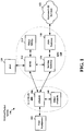
- FIG. 1 is a diagram illustrating an LTE network architecture 100.
- the LTE network architecture 100 may be referred to as an Evolved Packet System (EPS) 100.
- the EPS 100 may include one or more user equipment (UE) 102, an Evolved UMTS Terrestrial Radio Access Network (E-UTRAN) 104, an Evolved Packet Core (EPC) 110, a Home Subscriber Server (HSS) 120, and an Operator's IP Services 122.
- the EPS can interconnect with other access networks, but for simplicity those entities/interfaces are not shown.
- the EPS provides packet-switched services, however, as those skilled in the art will readily appreciate, the various concepts presented throughout this disclosure may be extended to networks providing circuit-switched services.
- the E-UTRAN includes the evolved Node B (eNB) 106 and other eNBs 108.
- the eNB 106 provides user and control planes protocol terminations toward the UE 102.
- the eNB 106 may be connected to the other eNBs 108 via a backhaul (e.g., an X2 interface).
- the eNB 106 may also be referred to as a base station, a base transceiver station, a radio base station, a radio transceiver, a transceiver function, a basic service set (BSS), an extended service set (ESS), or some other suitable terminology.
- the eNB 106 provides an access point to the EPC 110 for a UE 102.
- Examples of UEs 102 include a cellular phone, a smart phone, a session initiation protocol (SIP) phone, a laptop, a personal digital assistant (PDA), a satellite radio, a global positioning system, a multimedia device, a video device, a digital audio player (e.g., MP3 player), a camera, a game console, or any other similar functioning device.
- SIP session initiation protocol
- PDA personal digital assistant
- the UE 102 may also be referred to by those skilled in the art as a mobile station, a subscriber station, a mobile unit, a subscriber unit, a wireless unit, a remote unit, a mobile device, a wireless device, a wireless communications device, a remote device, a mobile subscriber station, an access terminal, a mobile terminal, a wireless terminal, a remote terminal, a handset, a user agent, a mobile client, a client, or some other suitable terminology.
- the eNB 106 is connected by an S1 interface to the EPC 110.
- the EPC 110 includes a Mobility Management Entity (MME) 112, other MMEs 114, a Serving Gateway 116, and a Packet Data Network (PDN) Gateway 118.
- MME Mobility Management Entity
- PDN Packet Data Network
- the MME 112 is the control node that processes the signaling between the UE 102 and the EPC 110.
- the MME 112 provides bearer and connection management. All user IP packets are transferred through the Serving Gateway 116, which itself is connected to the PDN Gateway 118.
- the PDN Gateway 118 provides UE IP address allocation as well as other functions.
- the PDN Gateway 118 is connected to the Operator's IP Services 122.
- the Operator's IP Services 122 may include the Internet, the Intranet, an IP Multimedia Subsystem (IMS), and a PS Streaming Service (PSS).
- IMS IP Multimedia Subsystem
- PSS PS Streaming Service
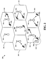
- FIG. 2 is a diagram illustrating an example of an access network 200 in an LTE network architecture.
- the access network 200 is divided into a number of cellular regions (cells) 202.
- One or more lower power class eNBs 208 may have cellular regions 210 that overlap with one or more of the cells 202.
- the lower power class eNB 208 may be a femto cell (e.g., home eNB (HeNB)), pico cell, micro cell, or remote radio head (RRH).
- HeNB home eNB
- RRH remote radio head
- the macro eNBs 204 are each assigned to a respective cell 202 and are configured to provide an access point to the EPC 110 for all the UEs 206 in the cells 202.
- the eNBs 204 are responsible for all radio related functions including radio bearer control, admission control, mobility control, scheduling, security, and connectivity to the serving gateway 116.
- the modulation and multiple access scheme employed by the access network 200 may vary depending on the particular telecommunications standard being deployed.
- OFDM is used on the DL
- SC-FDMA is used on the UL to support both frequency division duplexing (FDD) and time division duplexing (TDD).
- FDD frequency division duplexing
- TDD time division duplexing
- FDD frequency division duplexing
- TDD time division duplexing
- EV-DO Evolution-Data Optimized
- UMB Ultra Mobile Broadband
- EV-DO and UMB are air interface standards promulgated by the 3rd Generation Partnership Project 2 (3GPP2) as part of the CDMA2000 family of standards and employs CDMA to provide broadband Internet access to mobile stations. These concepts may also be extended to Universal Terrestrial Radio Access (UTRA) employing Wideband-CDMA (W-CDMA) and other variants of CDMA, such as TD-SCDMA; Global System for Mobile Communications (GSM) employing TDMA; and Evolved UTRA (E-UTRA), IEEE 802.11 (Wi-Fi), IEEE 802.16 (WiMAX), IEEE 802.20, and Flash-OFDM employing OFDMA.
- UTRA, E-UTRA, UMTS, LTE and GSM are described in documents from the 3GPP organization.
- CDMA2000 and UMB are described in documents from the 3GPP2 organization. The actual wireless communication standard and the multiple access technology employed will depend on the specific application and the overall design constraints imposed on the system.
- the eNBs 204 may have multiple antennas supporting MIMO technology.
- MIMO technology enables the eNBs 204 to exploit the spatial domain to support spatial multiplexing, beamforming, and transmit diversity.
- Spatial multiplexing may be used to transmit different streams of data simultaneously on the same frequency.
- the data steams may be transmitted to a single UE 206 to increase the data rate or to multiple UEs 206 to increase the overall system capacity. This is achieved by spatially precoding each data stream (i.e., applying a scaling of an amplitude and a phase) and then transmitting each spatially precoded stream through multiple transmit antennas on the DL.
- the spatially precoded data streams arrive at the UE(s) 206 with different spatial signatures, which enables each of the UE(s) 206 to recover the one or more data streams destined for that UE 206.
- each UE 206 transmits a spatially precoded data stream, which enables the eNB 204 to identify the source of each spatially precoded data stream.
- Beamforming may be used to focus the transmission energy in one or more directions. This may be achieved by spatially precoding the data for transmission through multiple antennas. To achieve good coverage at the edges of the cell, a single stream beamforming transmission may be used in combination with transmit diversity.
- OFDM is a spread-spectrum technique that modulates data over a number of subcarriers within an OFDM symbol.
- the subcarriers are spaced apart at precise frequencies. The spacing provides "orthogonality" that enables a receiver to recover the data from the subcarriers.
- a guard interval e.g., cyclic prefix
- the UL may use SC-FDMA in the form of a DFT-spread OFDM signal to compensate for high peak-to-average power ratio (PAPR).
- PAPR peak-to-average power ratio
- FIG. 3 is a diagram 300 illustrating an example of a DL frame structure in LTE.
- a frame (10 ms) may be divided into 10 equally sized subframes. Each subframe may include two consecutive time slots.
- a resource grid may be used to represent two time slots, each time slot including a resource block.
- the resource grid is divided into multiple resource elements.
- a resource block contains 12 consecutive subcarriers in the frequency domain and, for a normal cyclic prefix in each OFDM symbol, 7 consecutive OFDM symbols in the time domain, or 84 resource elements.
- For an extended cyclic prefix a resource block contains 6 consecutive OFDM symbols in the time domain and has 72 resource elements.
- Some of the resource elements, as indicated as R 302, 304, include DL reference signals (DL-RS).
- DL-RS DL reference signals
- the DL-RS include Cell-specific RS (CRS) (also sometimes called common RS) 302 and UE-specific RS (UE-RS) 304.
- UE-RS 304 are transmitted only on the resource blocks upon which the corresponding physical DL shared channel (PDSCH) is mapped.
- PDSCH physical DL shared channel
- the number of bits carried by each resource element depends on the modulation scheme. Thus, the more resource blocks that a UE receives and the higher the modulation scheme, the higher the data rate for the UE.
- FIG. 4 is a diagram 400 illustrating an example of an UL frame structure in LTE.
- the available resource blocks for the UL may be partitioned into a data section and a control section.
- the control section may be formed at the two edges of the system bandwidth and may have a configurable size.
- the resource blocks in the control section may be assigned to UEs for transmission of control information.
- the data section may include all resource blocks not included in the control section.
- the UL frame structure results in the data section including contiguous subcarriers, which may allow a single UE to be assigned all of the contiguous subcarriers in the data section.
- a UE may be assigned resource blocks 410a, 410b in the control section to transmit control information to an eNB.
- the UE may also be assigned resource blocks 420a, 420b in the data section to transmit data to the eNB.
- the UE may transmit control information in a physical UL control channel (PUCCH) on the assigned resource blocks in the control section.
- the UE may transmit only data or both data and control information in a physical UL shared channel (PUSCH) on the assigned resource blocks in the data section.
- a UL transmission may span both slots of a subframe and may hop across frequency.
- a set of resource blocks may be used to perform initial system access and achieve UL synchronization in a physical random access channel (PRACH) 430.
- the PRACH 430 carries a random sequence and cannot carry any UL data/signaling.
- Each random access preamble occupies a bandwidth corresponding to six consecutive resource blocks.
- the starting frequency is specified by the network. That is, the transmission of the random access preamble is restricted to certain time and frequency resources. There is no frequency hopping for the PRACH.
- the PRACH attempt is carried in a single subframe (1 ms) or in a sequence of few contiguous subframes and a UE can make only a single PRACH attempt per frame (10 ms).
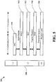
- FIG. 5 is a diagram 500 illustrating an example of a radio protocol architecture for the user and control planes in LTE.
- the radio protocol architecture for the UE and the eNB is shown with three layers: Layer 1, Layer 2, and Layer 3.
- Layer 1 (L1 layer) is the lowest layer and implements various physical layer signal processing functions.
- the L1 layer will be referred to herein as the physical layer 506.
- Layer 2 (L2 layer) 508 is above the physical layer 506 and is responsible for the link between the UE and eNB over the physical layer 506.
- the L2 layer 508 includes a media access control (MAC) sublayer 510, a radio link control (RLC) sublayer 512, and a packet data convergence protocol (PDCP) 514 sublayer, which are terminated at the eNB on the network side.
- MAC media access control
- RLC radio link control
- PDCP packet data convergence protocol
- the UE may have several upper layers above the L2 layer 508 including a network layer (e.g., IP layer) that is terminated at the PDN gateway 118 on the network side, and an application layer that is terminated at the other end of the connection (e.g., far end UE, server, etc.).
- IP layer e.g., IP layer
- the PDCP sublayer 514 provides multiplexing between different radio bearers and logical channels.
- the PDCP sublayer 514 also provides header compression for upper layer data packets to reduce radio transmission overhead, security by ciphering the data packets, and handover support for UEs between eNBs.
- the RLC sublayer 512 provides segmentation and reassembly of upper layer data packets, retransmission of lost data packets, and reordering of data packets to compensate for out-of-order reception due to hybrid automatic repeat request (HARQ).
- HARQ hybrid automatic repeat request
- the MAC sublayer 510 provides multiplexing between logical and transport channels.
- the MAC sublayer 510 is also responsible for allocating the various radio resources (e.g., resource blocks) in one cell among the UEs.
- the MAC sublayer 510 is also responsible for HARQ operations.
- the radio protocol architecture for the UE and eNB is substantially the same for the physical layer 506 and the L2 layer 508 with the exception that there is no header compression function for the control plane.
- the control plane also includes a radio resource control (RRC) sublayer 516 in Layer 3 (L3 layer).
- RRC sublayer 516 is responsible for obtaining radio resources (i.e., radio bearers) and for configuring the lower layers using RRC signaling between the eNB and the UE.
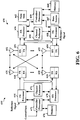
- FIG. 6 is a block diagram of an eNB 610 in communication with a UE 650 in an access network.
- upper layer packets from the core network are provided to a controller/processor 675.
- the controller/processor 675 implements the functionality of the L2 layer.
- the controller/processor 675 provides header compression, ciphering, packet segmentation and reordering, multiplexing between logical and transport channels, and radio resource allocations to the UE 650 based on various priority metrics.
- the controller/processor 675 is also responsible for HARQ operations, retransmission of lost packets, and signaling to the UE 650.
- the transmit (TX) processor 616 implements various signal processing functions for the L1 layer (i.e., physical layer).
- the signal processing functions includes coding and interleaving to facilitate forward error correction (FEC) at the UE 650 and mapping to signal constellations based on various modulation schemes (e.g., binary phase-shift keying (BPSK), quadrature phase-shift keying (QPSK), M-phase-shift keying (M-PSK), M-quadrature amplitude modulation (M-QAM)).
- FEC forward error correction
- BPSK binary phase-shift keying
- QPSK quadrature phase-shift keying
- M-PSK M-phase-shift keying
- M-QAM M-quadrature amplitude modulation
- Each stream is then mapped to an OFDM subcarrier, multiplexed with a reference signal (e.g., pilot) in the time and/or frequency domain, and then combined together using an Inverse Fast Fourier Transform (IFFT) to produce a physical channel carrying a time domain OFDM symbol stream.
- the OFDM stream is spatially precoded to produce multiple spatial streams.
- Channel estimates from a channel estimator 674 may be used to determine the coding and modulation scheme, as well as for spatial processing.
- the channel estimate may be derived from a reference signal and/or channel condition feedback transmitted by the UE 650.
- Each spatial stream is then provided to a different antenna 620 via a separate transmitter 618TX.
- Each transmitter 618TX modulates an RF carrier with a respective spatial stream for transmission.
- each receiver 654RX receives a signal through its respective antenna 652.
- Each receiver 654RX recovers information modulated onto an RF carrier and provides the information to the receive (RX) processor 656.
- the RX processor 656 implements various signal processing functions of the L1 layer.
- the RX processor 656 performs spatial processing on the information to recover any spatial streams destined for the UE 650. If multiple spatial streams are destined for the UE 650, they may be combined by the RX processor 656 into a single OFDM symbol stream.
- the RX processor 656 then converts the OFDM symbol stream from the time-domain to the frequency domain using a Fast Fourier Transform (FFT).
- FFT Fast Fourier Transform
- the symbols on each subcarrier, and the reference signal, is recovered and demodulated by determining the most likely signal constellation points transmitted by the eNB 610. These soft decisions may be based on channel estimates computed by the channel estimator 658. The soft decisions are then decoded and deinterleaved to recover the data and control signals that were originally transmitted by the eNB 610 on the physical channel. The data and control signals are then provided to the controller/processor 659.
- the controller/processor 659 implements the L2 layer.
- the controller/processor can be associated with a memory 660 that stores program codes and data.
- the memory 660 may be referred to as a computer-readable medium.
- the controller/processor 659 provides demultiplexing between transport and logical channels, packet reassembly, deciphering, header decompression, control signal processing to recover upper layer packets from the core network.
- the upper layer packets are then provided to a data sink 662, which represents all the protocol layers above the L2 layer.
- Various control signals may also be provided to the data sink 662 for L3 processing.
- the controller/processor 659 is also responsible for error detection using an acknowledgement (ACK) and/or negative acknowledgement (NACK) protocol to support HARQ operations.
- ACK acknowledgement
- NACK negative acknowledgement
- a data source 667 is used to provide upper layer packets to the controller/processor 659.
- the data source 667 represents all protocol layers above the L2 layer.
- the controller/processor 659 implements the L2 layer for the user plane and the control plane by providing header compression, ciphering, packet segmentation and reordering, and multiplexing between logical and transport channels based on radio resource allocations by the eNB 610.
- the controller/processor 659 is also responsible for HARQ operations, retransmission of lost packets, and signaling to the eNB 610.
- Channel estimates derived by a channel estimator 658 from a reference signal or feedback transmitted by the eNB 610 may be used by the TX processor 668 to select the appropriate coding and modulation schemes, and to facilitate spatial processing.
- the spatial streams generated by the TX processor 668 are provided to different antenna 652 via separate transmitters 654TX. Each transmitter 654TX modulates an RF carrier with a respective spatial stream for transmission.
- the UL transmission is processed at the eNB 610 in a manner similar to that described in connection with the receiver function at the UE 650.
- Each receiver 618RX receives a signal through its respective antenna 620.
- Each receiver 618RX recovers information modulated onto an RF carrier and provides the information to a RX processor 670.
- the RX processor 670 may implement the L1 layer.
- the controller/processor 675 implements the L2 layer.
- the controller/processor 675 can be associated with a memory 676 that stores program codes and data.
- the memory 676 may be referred to as a computer-readable medium.
- the control/processor 675 provides demultiplexing between transport and logical channels, packet reassembly, deciphering, header decompression, control signal processing to recover upper layer packets from the UE 650.
- Upper layer packets from the controller/processor 675 may be provided to the core network.
- the controller/processor 675 is also responsible for error detection using an ACK and/or NACK protocol to support HARQ operations.
- the TDD configurations may have fixed subframes and flexible subframes.
- Fixed subframes are each designated exclusively as a downlink (DL or D) subframe, an uplink (UL or U) subframe or a special (S) subframe.
- Flexible subframes also referred to herein as "dynamic” or “adaptive” subframes, may be designated as either an UL subframe or a DL subframe.
- a serving cell and a neighboring cell experience different levels and types of interference.
- Simulation results show there are both eNB-to-eNB interference and UE-to-UE interference when corresponding subframes of a serving cell and a neighboring cell are different link-type subframes, with the eNB-to-eNB interference being at a higher level.
- eNB-to-eNB interference is high when the subframe of the serving cell is an UL subframe and the corresponding subframe of the neighboring cell is a DL subframe. This scenario is referred to as a "UL-DL coexistence" scenario.
- Performance of a serving cell subjected to one or both of eNB-to-eNB interference and UE-to-UE interference may be improved through UL power control and DL power control, wherein the power control may be one of an open loop power control type or a closed loop power control type.
- performance may be improved by boosting the UL transmit power to improve PUSCH/PUCCH performance in the impacted (i.e., interfered with) UL subframe, wherein the impacted UL subframe corresponds to a serving-cell UL subframe that coexists with a neighboring-cell DL subframe.
- performance may be improved by decreasing the DL transmit power in the neighboring cell to minimize the interference on the impacted UL sub frame.
- FIG. 7 illustrates a UL-DL coexistence scenario 700, in which a first cell 702 serving a first UE 704 coexists with a second cell 706 serving a second UE 708.
- the first cell 702 is a serving cell and the second cell 706 is a neighboring cell.
- the TDD configuration 710 of the first cell 702 is configuration 1
- the TDD configuration 712 of the second cell 706 is configuration 2.
- the corresponding subframes of the TDD configurations are the same or common in subframes 0, 1, 3 and 5.
- the serving cell 702 is an UL subframe while the neighboring cell 706 is a DL subframe.
- the fourth subframe 714 is a UL-DL coexistence subframe.
- UE-UE interference 716 to the neighboring cell and eNB-eNB interference 718 to the serving cell is present.
- the UE-UE interference 716 is typically low while the eNB-eNB interference 718 is typically high.
- the UL transmit power in the serving cell 702 may be conservatively set toward the low side. However, because the UE-UE interference 716 to the neighboring cell is generally quite low, a more aggressive, i.e., higher, UL transmit power in the serving cell is possible. Also, an aggressive UL TX power setting in the serving cell is desirable due to high eNB-eNB interference 718 from the neighboring cell 706.
- the open loop power control parameters (P O_nominal_PUSCH + P O_UE_PUSCH_UL-DL , ⁇ ) are used for UL transmission by the UE 704.
- the open loop power control parameters (P O , ⁇ _UL_DL ) are used for UL transmission by the UE 704.
- a third approach two sets of (P O , ⁇ ) are defined, each having a different P O parameter and a different ⁇ parameter corresponding to the coexistence condition of the particular subframe.
- the open loop power control parameters P O_nominal_PUSCH + P O_UE_PUSCH_UL-UL , ⁇ _UL_UL ) are used for UL transmission by the UE 704.
- the open loop power control parameters (P O_nominal_PUSCH + P O_UE_PUSCH_UL-DL , ⁇ _UL_DL ) are for UL transmission by the UE 704.
- the ID of the neighboring cell 706 may be determined by selecting the highest RSRP from the UE's RSRP measurements of the neighboring cells.
- the TDD configuration of the neighboring cell 706 may be obtained through an X2 interface message between a base station 728 of the serving cell 702 and a base station 730 of the neighboring cell 706.
- FIG. 8 illustrates various subframe coexistence conditions 800 among TDD subframes in a number of cells 802, 804, 806.
- a first UE 808 within a first cell 802 is close to a second cell 804.
- the first cell 802 has a first TDD configuration 810 while the second cell 804 has a second TDD configuration 812.
- the third subframe 814 of the first cell TDD configuration 810 and the second cell TDD configuration 812 the first cell 802 is in an UL direction while the second cell 804 is in a DL direction.
- the first cell 802 is subjected to eNB-eNB interference 816 while a UE 818 within the second cell 804 is subjected to UE-UE interference 820.
- the parameters (P O , ⁇ ) selected for UL transmission by the first UE 808 in the third subframe are (P O_nominal_PUSCH + P O_UE_PUSCH_UL-DL , ⁇ ).
- the first cell 802 is in an UL direction and the second cell 808 is in an UL direction.
- the parameters (P O , ⁇ ) selected for UL transmission by the first UE 808 in the second subframe are (P O_nominal_PUSCH + P O_UE_PUSCH_UL-UL , ⁇ ).
- a second UE 824 within the first cell 802 is close to a third cell 806.
- the first cell 802 has a first TDD configuration 810 while the third cell 806 that has a third TDD configuration 826.
- the first cell 802 is in an UL direction while the third cell 806 is in a DL direction.
- the parameters (P O , ⁇ ) selected for UL transmission by the second UE 824 in the third subframe are (P O_nominal_PUSCH + P O_UE_PUSCH_UL-DL , ⁇ ).
- the first cell 802 is in an UL direction and the third cell 806 is in an UL direction.
- the parameters (P O , ⁇ ) selected for UL transmission by the second UE 824 in the second subframe are (P O_nominal_PUSCH + P O_UEPUSCH_UL-UL , ⁇ ).
- performance of a serving cell subjected to one or both of eNB-to-eNB interference and UE-to-UE interference may be improved through DL power control by decreasing the DL transmit power in the neighboring cell to minimize the interference on the impacted UL subframe in the serving cell.
- the eNB in the neighboring that is to transmit based on such DL power control is treated as a UE and the open loop power control parameters (Po, ⁇ ) of a UE in the neighboring cell are applied to that eNB so that interference to the eNB in the serving cell may be controlled.
- the open loop power control parameters (Po, ⁇ ) are used for eNB DL power control.
- a normal fixed DL power is used for eNB DL power control.
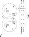
- FIG. 9 illustrates various coexistence scenarios 900 among a first cell 902 having a first eNB 904 and a first UE 918 and a second cell 906 having a second eNB 908 and a second UE 916.
- the first cell 902 is a neighboring cell and the second cell 906 is a serving cell.
- the TDD configuration 910 of the first cell 902 is configuration 1
- the TDD configuration 912 of the second cell 906 is configuration 2.
- the corresponding subframes of the TDD configurations are the same or common in subframes 0, 1, 2 and 4.
- subframes 0 and 4 are common DL subframes, while subframe 1 is a common special subframe. Fixed, full DL transmit power will be used by the eNB 908 in the serving cell 906 during each of these subframes.
- the neighboring cell 902 is a UL subframe while the serving cell 906 is an DL subframe.
- the third subframe 922 is a DL-UL coexistence subframe.
- UE-to-UE interference 914 from the UE 918 in the neighboring cell 902 to the UE 916 in the serving cell 906 is present.
- eNB-to-eNB interference 920 from the eNB 908 in the serving cell 906 to the eNB 904 in the neighboring cell 902 is present.
- the DL transmit power of the eNB 908 in the serving cell 906 is set based on the UL open loop power control parameters (Po, ⁇ ) of the neighboring cell 902 on the subframe.
- the power control parameters (Po, ⁇ ) may be (P O_nominal_PUSCH + P O_UE_PUSCH_UL-DL , ⁇ ).
- the DL transmit power of the eNB 908 of the serving cell 906 in the third subframe would be set in accordance with these parameters and would essentially be equal to the UL transmit power used by the UE 918 in the neighboring cell 902 on the same subframe.
- the TDD configuration of the neighboring cell 902 may be obtained through an X2 interface message between a base station 904 of the neighboring cell 902 and a base station 908 of the serving cell 906.
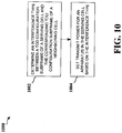
- FIG. 10 is a flow chart 1000 of a method of open loop power control for wireless communication.
- the method may be performed by an apparatus, e.g. a UE or an eNB.
- an interference type between a TDD configuration subframe of a serving cell and a corresponding TDD configuration subframe of a neighboring cell is determined.
- transmit power for an apparatus in the serving cell is set based on the interference type.
- FIG. 11 is a flow chart 1100 of a method of UL open loop power control for wireless communication based on the flow chart of FIG. 10 , in the case where the apparatus in the serving cell is a UE and the transmit power corresponds to an UL open loop power control.
- the method may be performed by a UE.
- a UL-UL interference type is identified when corresponding subframes of a serving cell and a neighboring cell are UL subframes. This type of identification corresponds to, for example, subframe 2 of FIG. 7 .
- a UL-DL interference type is identified when corresponding subframes of the serving cell and the neighboring cell comprise an UL subframe in the serving cell and a DL subframe in the neighboring cell. This type of identification corresponds to, for example, subframe 3 of FIG. 7 .
- a set of UL open loop power control parameters is applied to a UE in the serving cell based on the interference type.
- the set of UL open loop control parameters may be a UE specific component P O and a cell specific parameter ⁇ , as included in the open loop power control equation described above.
- a first P O is applied in the UL subframe with UL-UL interference type and a second P O is applied in the UL subframe with UL-DL interference type.
- a first ⁇ is appliedin the UL subframe with UL-UL interference type and a second ⁇ is applied in the UL subframe with UL-DL interference type.
- both of a first P O and a first ⁇ are applied in the UL subframe with UL-UL interference type, while both of a second P O and a second ⁇ are applied in the UL subframe with UL-DL interference type.
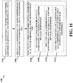
- FIG. 12 is a flow chart 1200 of a method of DL power control for wireless communication based on the method of FIG. 10 , in the case where the apparatus in the serving cell is a eNB and the transmit power corresponds to a DL transmit power for use by the eNB. This method may be performed by the eNB.
- a DL-DL interference type is identified when corresponding subframes of the serving cell and the neighboring cell are both downlink subframes or both special subframes. This type of identification corresponds to, for example, subframes 0, 1, and 4 of FIG. 9 .
- a DL-UL interference type is identified when corresponding subframes of the serving cell and the neighboring cell include a DL subframe in the serving cell and an UL subframe in the neighboring cell. This type of identification corresponds to, for example, subframe 3 of FIG. 9 .
- the DL transmit power is set at a fixed, full power DL transmission.
- the DL transmit power is set according to open loop power control parameters (e.g., P O and ⁇ ) of the neighboring cell.
- performance of a serving cell subjected to one or both of eNB-to-eNB interference and UE-to-UE interference may be improved through UL power control by boosting the UL transmit power.
- a power boost is provided by using different power control loops for different sets of TDD configuration subframes. These sets of subframes are formed based on coexistence conditions of corresponding subframes of a serving cell and a neighboring cell.
- non-UL/DL coexistence subframes Corresponding subframes that have a UL in the serving cell subframe and a UL in the neighboring cell subframe (referred to herein as “non-UL/DL coexistence" subframes) are designated as anchor subframes. Corresponding subframes that have a UL in the serving cell subframe and a DL in the neighboring cell subframe (referred to herein as “UL/DL coexistence” subframes) are designated as non-anchor subframes.
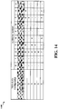
- FIG. 13 illustrates several examples 1300 of different coexisting serving cells and neighboring cells having respective TDD configurations.
- a serving cell of TDD configuration 1 coexists with neighboring cell of TDD configuration 2
- subframes 2/7 are non-UL/DL coexistence subframes and are thus designated anchor subframes.
- Subframes 3/8 are UL/DL coexistence subframes and thus designated non-anchor subframes.
- subframes 2/3/4 are non-UL/DL coexistence subframes and are thus designated anchor subframes.
- Subframes 7/8 are UL/DL coexistence subframes and are thus designated non-anchor subframes.
- subframes 2/3 are non-UL/DL coexistence subframes and are thus designated anchor subframes.
- Subframe 4 is a UL/DL coexistence subframe and is thus designated a non-anchor subframe.
- subframes 2 is a non-UL/DL coexistence subframe and is thus designated an anchor subframe.
- Subframes 3/7/8 are UL/DL coexistence subframes and are thus designated non-anchor subframes.
- anchor subframes and non-anchor subframes are defined, different power control loops are determined for the anchor subframes and the non-anchor subframes respectively.
- Anchor subframes follow the TPC command that is generated based on the decoding status of the anchor subframe
- non-anchor subframes follow the TPC command that is generated based on the decoding status of the non-anchor subframe.
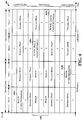
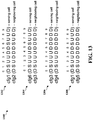
- a new timeline is established for TDD configuration 0 as shown in the table 1400 illustrated in FIG. 14 .
- the eNB can map the TPC command from two loops of anchor and non-anchor subframe set to corresponding DL subframe whose effective subframe is in the same subframe set as shown in the table 1400 illustrated in FIG. 14 .
- FIG. 15 is a flow chart 1500 of a method of UL closed loop power control for wireless communication.
- the method may be performed by a UE.
- subframes of a TDD configuration of a serving cell are grouped into a set of anchor subframes and a set of non-anchor subframes. Such grouping may be based on a comparison of corresponding subframes of the serving cell and a neighboring cell.
- one or more UL subframe of the serving cell are designated anchor frames when corresponding subframes of the serving cell and the neighboring cell comprise an UL subframe in the serving cell and an UL subframe in the neighboring cell.
- This type of designation corresponds to, for example, subframes 2/7 in case 1302 of FIG. 13 .
- one or more UL subframe of the serving cell are designated non-anchor subframes when corresponding subframes of the serving cell and the neighboring cell comprise an UL subframe in the serving cell and a DL subframe in the neighboring cell.
- This type of designation corresponds to, for example, subframes 3/8 in case 1302 of FIG. 13 .
- a respective UL transmit power is calculated for the set of anchor subframes and for the set of non-anchor subframes.
- a separate TPC command is received for the set of anchor subframes and the set of non-anchor subframes.
- the UL transmit power for anchor subframes is calculated by accumulating or absolutely setting UL transmit powers based on the TPC command calculated in subframes belonging to the set of anchor subframes.
- the UL transmit power for non-anchor subframes is calculated by accumulating or absolutely setting UL transmit powers based on the TPC command calculated in subframes belonging to the set of non-anchor subframes.
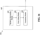
- FIG. 16 is a conceptual data flow diagram 1600 illustrating the data flow between different modules/means/components in an exemplary apparatus 1602 for open loop power control.
- the apparatus may be a UE or and eNB.
- the apparatus includes an interference determining module 1604 that determines an interference type between a time division duplex (TDD) configuration subframe of a serving cell and a corresponding TDD configuration subframe of a neighboring cell, a power setting module 1606 that sets a transmit power for an apparatus in the serving cell based on the interference type, and a transmission module 1608 that transmits information based on the transmit power.
- TDD time division duplex
- the apparatus may include additional modules that perform each of the steps of the algorithm in the aforementioned flow chart of FIG 10 .
- each step in the aforementioned flow chart of FIG. 10 may be performed by a module and the apparatus may include one or more of those modules.
- the modules may be one or more hardware components specifically configured to carry out the stated processes/algorithm, implemented by a processor configured to perform the stated processes/algorithm, stored within a computer-readable medium for implementation by a processor, or some combination thereof.
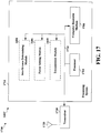
- FIG. 17 is a diagram 1700 illustrating an example of a hardware implementation for an apparatus 1602' employing a processing system 1714 for open loop power control.
- the processing system 1714 may be implemented with a bus architecture, represented generally by the bus 1724.
- the bus 1724 may include any number of interconnecting buses and bridges depending on the specific application of the processing system 1714 and the overall design constraints.
- the bus 1724 links together various circuits including one or more processors and/or hardware modules, represented by the processor 1704, the modules 1604, 1606, 1608, and the computer-readable medium 1706.
- the bus 1724 may also link various other circuits such as timing sources, peripherals, voltage regulators, and power management circuits, which are well known in the art, and therefore, will not be described any further.
- the processing system 1714 may be coupled to a transceiver 1710.
- the transceiver 1710 is coupled to one or more antennas 1720.
- the transceiver 1710 provides a means for communicating with various other apparatus over a transmission medium.
- the processing system 1714 includes a processor 1704 coupled to a computer-readable medium 1706.
- the processor 1704 is responsible for general processing, including the execution of software stored on the computer-readable medium 1706.
- the software when executed by the processor 1704, causes the processing system 1714 to perform the various functions described supra for any particular apparatus.
- the computer-readable medium 1706 may also be used for storing data that is manipulated by the processor 1704 when executing software.
- the processing system further includes at least one of the modules 1604, 1606 and 1608.
- the modules may be software modules running in the processor 1704, resident/stored in the computer readable medium 1706, one or more hardware modules coupled to the processor 1704, or some combination thereof.
- the processing system 1714 may be a component of the eNB 610 and may include the memory 676 and/or at least one of the TX processor 616, the RX processor 670, and the controller/processor 675.
- the processing system 1714 may be a component of the UE 650 and may include the memory 660 and/or at least one of the TX processor 668, the RX processor 656, and the controller/processor 659.
- the apparatus 1602/1602' for wireless communication includes means for determining an interference type between a TDD configuration subframe of a serving cell and a corresponding TDD configuration subframe of a neighboring cell, and means for setting a transmit power for an apparatus in the serving cell based on the interference type.
- the aforementioned means may be one or more of the aforementioned modules of the apparatus 1602 and/or the processing system 1714 of the apparatus 1602' configured to perform the functions recited by the aforementioned means.
- the processing system 1714 may include the TX Processor 616, the RX Processor 670, and the controller/processor 675.
- the aforementioned means may be the TX Processor 616, the RX Processor 670, and the controller/processor 675 configured to perform the functions recited by the aforementioned means.
- the processing system 1714 may include the TX Processor 668, the RX Processor 656, and the controller/processor 659.
- the aforementioned means may be the TX Processor 668, the RX Processor 656, and the controller/processor 659 configured to perform the functions recited by the aforementioned means.
- FIG. 18 is a conceptual data flow diagram 1800 illustrating the data flow between different modules/means/components in an exemplary apparatus 1802 for UL open loop power control.
- the apparatus may be a UE.
- the apparatus 1802 includes an interference type identification module 1804 that identifies a UL-UL interference type when corresponding subframes of a serving cell and a neighboring cell are UL subframes, and identifies a UL-DL interference type when corresponding subframes of a serving cell and a neighboring cell include an UL subframe in the serving cell and a DL subframe in the neighboring cell.
- the apparatus 1802 also includes a UL open loop power control parameter module 1806 that applies a set of UL open loop power control parameters, including a UE specific component P O and a cell specific parameter ⁇ .
- the parameters are applied based on interference type. For example, in one arrangement, the parameter module 1806 applies a first P O for the subframe with UL-UL interference type and a second P O for the subframe with UL-DL interference type. In another arrangement, the parameter module 1806 applies a first ⁇ for the subframe with UL-UL interference type and a second ⁇ for the subframe with UL-DL interference type.
- the parameter module 1806 applies a first P O for the subframe with UL-UL interference type and a second P O for the subframe with UL-DL interference type and applies a first ⁇ for the subframe with UL-UL interference type and a second ⁇ for the subframe with UL-DL interference type.
- the apparatus 1802 further includes a transmission module 1808 that transmits information based on theset of UL open loop power control parameters, e.g., to eNB 1810.
- the apparatus 1802 may include additional modules that perform each of the steps of the algorithm in the aforementioned flow charts of FIG. 11 . As such, each step in the aforementioned flow charts of FIG. 11 may be performed by a module and the apparatus may include one or more of those modules.
- the modules may be one or more hardware components specifically configured to carry out the stated processes/algorithm, implemented by a processor configured to perform the stated processes/algorithm, stored within a computer-readable medium for implementation by a processor, or some combination thereof.
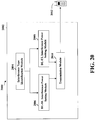
- FIG. 19 is a diagram 1900 illustrating an example of a hardware implementation for an apparatus 1802' employing a processing system 1914 for UL open loop power control.
- the processing system 1914 may be implemented with a bus architecture, represented generally by the bus 1924.
- the bus 1924 may include any number of interconnecting buses and bridges depending on the specific application of the processing system 1914 and the overall design constraints.
- the bus 1924 links together various circuits including one or more processors and/or hardware modules, represented by the processor 1904, the modules 1804, 1806, 1808, and the computer-readable medium 1906.
- the bus 1924 may also link various other circuits such as timing sources, peripherals, voltage regulators, and power management circuits, which are well known in the art, and therefore, will not be described any further.
- the processing system 1914 may be coupled to a transceiver 1910.
- the transceiver 1910 is coupled to one or more antennas 1920.
- the transceiver 1910 provides a means for communicating with various other apparatus over a transmission medium.
- the processing system 1914 includes a processor 1904 coupled to a computer-readable medium 1906.
- the processor 1904 is responsible for general processing, including the execution of software stored on the computer-readable medium 1906.
- the software when executed by the processor 1904, causes the processing system 1914 to perform the various functions described supra for any particular apparatus.
- the computer-readable medium 1906 may also be used for storing data that is manipulated by the processor 1904 when executing software.
- the processing system further includes at least one of the modules 1804, 1806, and 1808.
- the modules may be software modules running in the processor 1904, resident/stored in the computer readable medium 1906, one or more hardware modules coupled to the processor 1904, or some combination thereof.
- the processing system 1914 may be a component of the UE 650 and may include the memory 660 and/or at least one of the TX processor 668, the RX processor 656, and the controller/processor 659.
- the apparatus 1802/1802' for wireless communication includes means for determining an interference type that is configured to identify a UL-UL interference type when corresponding subframes of the serving cell and the neighboring cell are UL subframes, and identify a UL-DL interference type when corresponding subframes of the serving cell and the neighboring cell comprise an UL subframe in the serving cell and a DL subframe in the neighboring cell.
- the apparatus 1802/1802' also includes means for applying a set of UL open loop power control parameters, including a UE specific component P O and a cell specific parameter ⁇ .
- the means for applying a set of UL open loop control parameters may be configured to apply a first P O for the subframe with UL-UL interference type and a second P O for the subframe with UL-DL interference type.
- the means for applying a set of UL open loop power control parameters may also be configured to apply a first ⁇ for the subframe with UL-UL interference type and a second ⁇ for the subframe with UL-DL interference type.
- the means for applying a set of UL open loop power control parameters may also be configured to apply a first P O for the subframe with UL-UL interference type and a second P O for the subframe with UL-DL interference type, and apply a first ⁇ for the subframe with UL-UL interference type and a second ⁇ for the subframe with UL-DL interference type.
- the aforementioned means may be one or more of the aforementioned modules of the apparatus 1802 and/or the processing system 1914 of the apparatus 1802' configured to perform the functions recited by the aforementioned means.
- the processing system 1914 may include the TX Processor 668, the RX Processor 656, and the controller/processor 659.
- the aforementioned means may be the TX Processor 668, the RX Processor 656, and the controller/processor 659 configured to perform the functions recited by the aforementioned means.
- FIG. 20 is a conceptual data flow diagram 2000 illustrating the data flow between different modules/means/components in an exemplary apparatus 2002 for DL power control.
- the apparatus may be a eNB.
- the apparatus includes an interference type identification module 2004 that identifies a DL-DL interference type when corresponding subframes of a serving cell and a neighboring cell are both DL subframes or both special subframes, and identifies DL-UL interference type when corresponding subframes of the serving cell and the neighboring cell include a DL subframe in the serving cell and an UL subframe in the neighboring cell.
- the apparatus 2002 also includes a DL-DL interference power setting module 2006 that sets a DL transmit power at a fixed, full power DL transmission in cases of DL-DL interference, and a DL-UL interference power setting module that adjusts a DL transmit power according to UL open loop power control parameters (P O , ⁇ ) of the neighboring cell in cases of DL-UL interference.
- the apparatus 2002 also includes a transmission module 2010 that transmits information, e.g., to UE 2012, based on the set or adjusted DL transmit power.
- the apparatus 2002 may include additional modules that perform each of the steps of the algorithm in the aforementioned flow charts of FIG. 12 .
- each step in the aforementioned flow charts of FIG. 12 may be performed by a module and the apparatus may include one or more of those modules.
- the modules may be one or more hardware components specifically configured to carry out the stated processes/algorithm, implemented by a processor configured to perform the stated processes/algorithm, stored within a computer-readable medium for implementation by a processor, or some combination thereof.
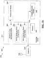
- FIG. 21 is a diagram 2100 illustrating an example of a hardware implementation for an apparatus 2002' employing a processing system 2114 for DL power control.
- the processing system 2114 may be implemented with a bus architecture, represented generally by the bus 2124.
- the bus 2124 may include any number of interconnecting buses and bridges depending on the specific application of the processing system 2114 and the overall design constraints.
- the bus 2124 links together various circuits including one or more processors and/or hardware modules, represented by the processor 2104, the modules 2004, 2006, 2008, 2010 and the computer-readable medium 2106.
- the bus 2124 may also link various other circuits such as timing sources, peripherals, voltage regulators, and power management circuits, which are well known in the art, and therefore, will not be described any further.
- the processing system 2114 may be coupled to a transceiver 2110.
- the transceiver 2110 is coupled to one or more antennas 2120.
- the transceiver 2110 provides a means for communicating with various other apparatus over a transmission medium.
- the processing system 2114 includes a processor 2104 coupled to a computer-readable medium 2106.
- the processor 2104 is responsible for general processing, including the execution of software stored on the computer-readable medium 2106.
- the software when executed by the processor 2104, causes the processing system 2114 to perform the various functions described supra for any particular apparatus.
- the computer-readable medium 2106 may also be used for storing data that is manipulated by the processor 2104 when executing software.
- the processing system further includes at least one of the modules 2004, 2006, 2008 and 2010.
- the modules may be software modules running in the processor 2104, resident/stored in the computer readable medium 2106, one or more hardware modules coupled to the processor 2104, or some combination thereof.
- the processing system 2114 may be a component of the eNB 610 and may include the memory 676 and/or at least one of the TX processor 616, the RX processor 670, and the controller/processor 675.
- the apparatus 2002/2002' for wireless communication includes means for determining an interference type that is configured to identify a DL-DL interference type when corresponding subframes of the serving cell and the neighboring cell are both DL subframes or both special subframes, and identify a DL-UL interference type when corresponding subframes of the serving cell and the neighboring cell comprise a DL subframe in the serving cell and an UL subframe in the neighboring cell.
- the apparatus 2002/2002' also includes means for setting a DL transmit power that is configured to set the DL transmit power at a fixed, full power DL transmission in cases of DL-DL interference, and means for setting a DL transmit power that is configured to adjust the DL transmit power according to UL open loop power control parameters of the neighboring cell in cases of DL-UL interference.
- the aforementioned means may be one or more of the aforementioned modules of the apparatus 2002 and/or the processing system 2114 of the apparatus 2002' configured to perform the functions recited by the aforementioned means.
- the processing system 2114 may include the TX Processor 616, the RX Processor 670, and the controller/processor 675.
- the aforementioned means may be the TX Processor 616, the RX Processor 670, and the controller/processor 675 configured to perform the functions recited by the aforementioned means.
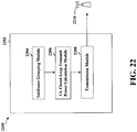
- FIG. 22 is a conceptual data flow diagram 2200 illustrating the data flow between different modules/means/components in an exemplary apparatus 2202 for UL closed loop power control.
- the apparatus may be a UE.
- the apparatus includes a subframe grouping module 2204 that groups subframes of a TDD configuration of a serving cell into a set of anchor subframes and a set of non-anchor subframes, and a UL closed loop transmit power calculation module 2206 that calculates a respective UL transmit power for the set of anchor subframes and for the set of non-anchor subframes.
- the calculation module also receives a separate TPC command for the set of anchor subframes and the set of non-anchor subframes.
- the apparatus 2002 also includes a transmission module 2208 that transmits information based on the calculated UL transmit power, e.g., to eNB 2210.
- the apparatus may include additional modules that perform each of the steps of the algorithm in the aforementioned flow charts of FIG. 15 .
- each step in the aforementioned flow charts of FIG. 15 may be performed by a module and the apparatus may include one or more of those modules.
- the modules may be one or more hardware components specifically configured to carry out the stated processes/algorithm, implemented by a processor configured to perform the stated processes/algorithm, stored within a computer-readable medium for implementation by a processor, or some combination thereof.
- FIG. 23 is a diagram 2300 illustrating an example of a hardware implementation for an apparatus 2202' employing a processing system 2314 for UL closed loop power control.
- the processing system 2314 may be implemented with a bus architecture, represented generally by the bus 2324.
- the bus 2324 may include any number of interconnecting buses and bridges depending on the specific application of the processing system 2314 and the overall design constraints.
- the bus 2324 links together various circuits including one or more processors and/or hardware modules, represented by the processor 2304, the modules 2204, 2206, 2208, and the computer-readable medium 2306.
- the bus 2324 may also link various other circuits such as timing sources, peripherals, voltage regulators, and power management circuits, which are well known in the art, and therefore, will not be described any further.
- the processing system 2314 may be coupled to a transceiver 2310.
- the transceiver 2310 is coupled to one or more antennas 2320.
- the transceiver 2310 provides a means for communicating with various other apparatus over a transmission medium.
- the processing system 2314 includes a processor 2304 coupled to a computer-readable medium 2306.
- the processor 2304 is responsible for general processing, including the execution of software stored on the computer-readable medium 2306.
- the software when executed by the processor 2304, causes the processing system 2314 to perform the various functions described supra for any particular apparatus.
- the computer-readable medium 2306 may also be used for storing data that is manipulated by the processor 2304 when executing software.
- the processing system further includes at least one of the modules 2204, 2206, and 2208.
- the modules may be software modules running in the processor 2304, resident/stored in the computer readable medium 2306, one or more hardware modules coupled to the processor 2304, or some combination thereof.
- the processing system 2314 may be a component of the UE 650 and may include the memory 660 and/or at least one of the TX processor 668, the RX processor 656, and the controller/processor 659.
- the apparatus 2202/2202' for wireless communication includes means for grouping subframes of a TDD configuration of a serving cell into a set of anchor subframes and a set of non-anchor subframes, and means for calculating a respective UL transmit power for the set of anchor subframes and for the set of non-anchor subframes.
- the means for calculating an UL transmit power includes means for receiving a separate TPC command for the set of anchor subframes and the set of non-anchor subframes.
- the aforementioned means may be one or more of the aforementioned modules of the apparatus 2202 and/or the processing system 2314 of the apparatus 2202' configured to perform the functions recited by the aforementioned means.
- the processing system 2314 may include the TX Processor 668, the RX Processor 656, and the controller/processor 659.
- the aforementioned means may be the TX Processor 668, the RX Processor 656, and the controller/processor 659 configured to perform the functions recited by the aforementioned means.
- DL open loop power setting at the effective point of new TDD configuration which includes: power setting for new cluster node when configuration changes from victim to aggressor, and power setting for neighbor cluster node when configuration changes from aggressor to victim.
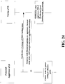
- FIG. 24 illustrates open loop power control when cluster configuration changes from victim to aggressor.
- potential aggressor eNB Upon decision of application of one new configuration, potential aggressor eNB notifies its configuration information to its neighbor eNB.
- the neighbor victim eNB responds with its measurement of pathloss, its thermal noise level, interference over thermal noise (IOT) margin (up to its uplink loading and normal UL interference) and other aggressor information if any.
- the neighbor eNB notifies other aggressor eNB node of the addition of new aggressor.
- the potential aggressor eNB tries to set its initial DL Tx power independently or together with other aggressor nodes.
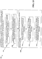
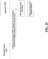
- FIG. 25 illustrates open loop power control when cluster configuration changes from aggressor to victim.
- potential victim eNB Upon decision of application of one new configuration, potential victim eNB notifies its configuration information, thermal noise level, IOT margin and pathloss measurement to its neighbor eNB.
- the neighbor aggressor eNB requests other victim's UL status and neighbor victim eNB notifies other aggressor eNB of its current updated status if any.
- the impacted aggressor eNB updates its initial Tx power based on up to dated victim eNB status.
- the optimal open loop Tx power setting of C is the solution of following linear optimization problem: Max TxPwrCp 1 + ... TxPwrCpn subjected to
- IOT margin for victim eNB can be set aggressively for single cluster optimization case.
- isolation threshold selection it is recommended to compensate the Tx power difference between enodeB and UE average uplink Tx power (for example, 70db +nodeb max Tx power - UE average UL Tx power) so that aggressor eNB looks like one UE for smooth interference control.
Claims (11)
- Un procédé de communication sans fil, comprenant :la détermination, par un appareil dans une cellule de desserte (702), d'un type d'interférence entre une sous-trame de configuration duplex à répartition dans le temps, TDD, de la cellule de desserte (702) et une sous-trame de configuration TDD correspondante d'une cellule voisine (706) ; etl'ajustement, par l'appareil, d'une puissance d'émission pour l'appareil dans la cellule de desserte (702) sur la base du type d'interférence,dans lequel l'appareil est un équipement utilisateur, UE, (704) et dans lequel l'ajustement de la puissance d'émission comprend : dans le cas où le type d'interférence est un type d'interférence liaison montante-liaison descendante, UL-DL, l'augmentation de la puissance d'émission comparativement à celle qu'elle est quand le type d'interférence est un type d'interférence liaison montante-liaison montante, UL-UL.
- Le procédé selon la revendication 1, dans lequel l'ajustement de la puissance d'émission comprend l'application d'un ensemble de paramètres de contrôle de puissance en boucle ouverte de liaison montante, UL, pour l'UE (704).
- Le procédé selon la revendication 2, dans lequel la détermination d'un type d'interférence comprend :l'identification d'un type d'interférence UL-UL lorsque des sous-trames correspondantes de la cellule de desserte (702) et de la cellule voisine (706) sont des sous-trames UL ; etl'identification d'un type d'interférence UL-DL lorsque des sous-trames correspondantes de la cellule de desserte et de la cellule voisine (706) comprennent une sous-trame UL dans la cellule de desserte (702) et une sous-trame de liaison descendante, DL, dans la cellule voisine (706).
- Le procédé selon la revendication 3, dans lequel l'ensemble de paramètres de contrôle de puissance en boucle ouverte UL comprend une composante Po spécifique à l'UE et un paramètre α spécifique à la cellule, et l'application d'un ensemble de paramètres de contrôle de puissance en boucle ouverte UL comprend l'application d'une première Po dans la sous-trame UL avec le type d'interférence UL-UL et d'une seconde Po dans la sous-trame UL avec le type d'interférence UL-DL.
- Le procédé selon la revendication 2, dans lequel l'ensemble de paramètres de contrôle de puissance en boucle ouverte UL comprend une composante Po spécifique à l'UE et un paramètre α spécifique à la cellule, et l'application d'un ensemble de paramètres de contrôle de puissance en boucle ouverte UL comprend l'application d'un premier α dans la sous-trame UL avec le type d'interférence UL-UL et d'un second α dans la sous-trame UL avec le type d'interférence UL-DL.
- Un appareil pour une communication sans fil, comprenant :un moyen pour déterminer un type d'interférence entre une sous-trame de configuration duplex à répartition dans le temps, TDD, d'une cellule de desserte (702) et une sous-trame de configuration TDD correspondante d'une cellule voisine (706) ; etun moyen pour ajuster une puissance d'émission pour l'appareil dans la cellule de desserte (702) sur la base du type d'interférence, dans lequel l'appareil est un équipement utilisateur, UE, (704) et dans lequel l'ajustement de la puissance d'émission comprend :
dans le cas où le type d'interférence est un type d'interférence liaison montante-liaison descendante, UL-DL, l'augmentation de la puissance d'émission comparativement à celle qu'elle est quand le type d'interférence est un type d'interférence liaison montante-liaison montante, UL-UL. - L'appareil selon la revendication 6, dans lequel le moyen pour ajuster une puissance d'émission comprend un moyen pour appliquer un ensemble de paramètres de contrôle de puissance en boucle ouverte de liaison montante, UL, pour l'UE (704).
- L'appareil selon la revendication 7, dans lequel le moyen pour déterminer un type d'interférence est configuré pour :identifier un type d'interférence UL-UL lorsque des sous-trames correspondantes de la cellule de desserte (702) et de la cellule voisine (706) sont des sous-trames UL ; etidentifier un type d'interférence UL-DL lorsque des sous-trames correspondantes de la cellule de desserte et de la cellule voisine (706) comprennent une sous-trame UL dans la cellule de desserte (702) et une sous-trame de liaison descendante, DL, dans la cellule voisine (706).
- L'appareil selon la revendication 8, dans lequel l'ensemble de paramètres de contrôle de puissance en boucle ouverte UL comprend une composante Po spécifique à l'UE et un paramètre α spécifique à la cellule, et le moyen pour appliquer un ensemble de paramètres de contrôle de puissance en boucle ouverte UL est configuré pour appliquer une première Po pour la sous-trame avec le type d'interférence UL-UL et une seconde Po pour la sous-trame avec le type d'interférence UL-DL.
- L'appareil selon la revendication 8, dans lequel l'ensemble de paramètres de contrôle de puissance en boucle ouverte UL comprend une composante Po spécifique à l'UE et un paramètre α spécifique à la cellule, et le moyen pour appliquer un ensemble de paramètres de contrôle de puissance en boucle ouverte UL est configuré pour appliquer un premier α dans la sous-trame UL avec le type d'interférence UL-UL et un second α dans la sous-trame UL avec le type d'interférence UL-DL.
- Un programme d'ordinateur, comprenant un code pour effectuer les étapes selon l'une des revendications 1 à 5 lorsqu'il est exécuté sur un ordinateur.
Applications Claiming Priority (1)
| Application Number | Priority Date | Filing Date | Title |
|---|---|---|---|
| PCT/CN2012/082577 WO2014056137A1 (fr) | 2012-10-08 | 2012-10-08 | Commande de puissance améliorée de liaison montante et de liaison descendante pour lte tdd eimta |
Publications (3)
| Publication Number | Publication Date |
|---|---|
| EP2904856A1 EP2904856A1 (fr) | 2015-08-12 |
| EP2904856A4 EP2904856A4 (fr) | 2016-04-27 |
| EP2904856B1 true EP2904856B1 (fr) | 2019-11-13 |
Family
ID=50476854
Family Applications (1)
| Application Number | Title | Priority Date | Filing Date |
|---|---|---|---|
| EP12886421.2A Active EP2904856B1 (fr) | 2012-10-08 | 2012-10-08 | Commande de puissance améliorée de liaison montante et de liaison descendante pour lte tdd eimta |
Country Status (6)
| Country | Link |
|---|---|
| US (2) | US9794051B2 (fr) |
| EP (1) | EP2904856B1 (fr) |
| JP (1) | JP6092401B2 (fr) |
| KR (1) | KR102023315B1 (fr) |
| CN (2) | CN104704889B (fr) |
| WO (1) | WO2014056137A1 (fr) |
Families Citing this family (24)
| Publication number | Priority date | Publication date | Assignee | Title |
|---|---|---|---|---|
| CN103379604B (zh) * | 2012-04-20 | 2018-04-27 | 北京三星通信技术研究有限公司 | 动态tdd小区中的上行功率控制方法 |
| WO2014056137A1 (fr) | 2012-10-08 | 2014-04-17 | Qualcomm Incorporated | Commande de puissance améliorée de liaison montante et de liaison descendante pour lte tdd eimta |
| US10091766B2 (en) * | 2013-04-05 | 2018-10-02 | Qualcomm Incorporated | Interference cancellation/suppression in TDD wireless communications systems |
| EP2802091A1 (fr) * | 2013-05-08 | 2014-11-12 | Panasonic Intellectual Property Corporation of America | Configuration de liaison montante-descendante TDD flexible avec sous-trames flexibles |
| EP3042529B1 (fr) | 2013-09-04 | 2020-04-01 | LG Electronics Inc. | Procédé et appareil de commande de puissance de liaison montante dans un système de communication sans fil |
| US20150319702A1 (en) * | 2014-05-02 | 2015-11-05 | Qualcomm Incorporated | Configuration of uplink open loop power control parameters |
| WO2017034258A1 (fr) * | 2015-08-21 | 2017-03-02 | 엘지전자 주식회사 | Procédé pour émettre ou recevoir un signal v2x dans un système de communication sans fil et dispositif pour mettre en œuvre ledit procédé |
| CN108028816B (zh) * | 2015-09-07 | 2021-12-10 | Lg电子株式会社 | 用于由使用fdr方案的设备消除自干扰的方法 |
| WO2017111807A1 (fr) * | 2015-12-24 | 2017-06-29 | Intel Corporation | Commande de puissance de liaison montante pour limitation de brouillage dans des réseaux cellulaires de type duplex intégral |
| EP3420758A4 (fr) * | 2016-02-24 | 2019-10-16 | Nokia Solutions and Networks Oy | Commande de puissance de transmission de liaison montante |
| WO2017181321A1 (fr) | 2016-04-18 | 2017-10-26 | 华为技术有限公司 | Procédé de commande de puissance, dispositif côté réseau, et équipement utilisateur |
| CN109156022B (zh) | 2016-06-22 | 2022-08-09 | 英特尔公司 | 用于全双工调度的通信设备和方法 |
| CN107872890B (zh) | 2016-09-28 | 2020-11-06 | 华为技术有限公司 | 一种无线通信系统中调度传输的方法及设备 |
| US10506523B2 (en) * | 2016-11-18 | 2019-12-10 | Qualcomm Incorporated | Subband set dependent uplink power control |
| WO2018128948A1 (fr) * | 2017-01-06 | 2018-07-12 | Intel IP Corporation | Évitement d'interférence entre nœuds |
| KR102319178B1 (ko) | 2017-03-24 | 2021-10-28 | 후아웨이 테크놀러지 컴퍼니 리미티드 | 간섭 측정 방법 및 관련 장치 |
| US10439789B2 (en) * | 2017-05-08 | 2019-10-08 | Skyworks Solutions, Inc. | Radio frequency communication systems with dynamic waveform control and power boost |
| CN108235797B (zh) * | 2017-12-28 | 2020-03-06 | 北京小米移动软件有限公司 | 确定路径损耗的方法及装置 |
| US10470136B1 (en) | 2018-08-10 | 2019-11-05 | At&T Intellectual Property I, L.P. | Downlink power control enhancements for multi-hop integrated access and backhaul |
| US11184232B2 (en) * | 2018-11-26 | 2021-11-23 | Eagle Technology, Llc | Radio frequency (RF) communication system providing enhanced RF equipment configuration updates for mobile vehicles based upon reward matrices and related methods |
| US11095360B2 (en) | 2018-11-26 | 2021-08-17 | Eagle Technology, Llc | Radio frequency (RF) communication system providing enhanced mobile vehicle positioning based upon reward matrices and related methods |
| US10757584B1 (en) | 2019-04-23 | 2020-08-25 | Sprint Spectrum L.P. | Use of different co-existing TDD configurations on a TDD carrier, with uplink beamforming to help minimize interference |
| WO2020222275A1 (fr) * | 2019-05-02 | 2020-11-05 | 株式会社Nttドコモ | Terminal utilisateur et procédé de communication sans fil |
| WO2023209428A1 (fr) * | 2022-04-26 | 2023-11-02 | Telefonaktiebolaget Lm Ericsson (Publ) | Interférence de liaison montante dans un réseau de communication |
Family Cites Families (24)
| Publication number | Priority date | Publication date | Assignee | Title |
|---|---|---|---|---|
| KR101229564B1 (ko) | 2006-06-12 | 2013-02-04 | 삼성전자주식회사 | 통신 시스템에서의 인접 섹터 간섭을 고려한 전력 제어 및스케줄링 방법 |
| US8195097B2 (en) | 2006-09-08 | 2012-06-05 | Qualcomm Incorporated | Serving sector interference broadcast and corresponding RL traffic power control |
| PL2080282T3 (pl) | 2006-10-03 | 2020-05-18 | Interdigital Technology Corporation | Sterowanie mocą nadawczą (oparte na cqi) łącza uplink z kombinacją pętli otwartej/pętli zamkniętej z osłabianiem zakłóceń dla e-utra |
| ATE526735T1 (de) | 2006-10-30 | 2011-10-15 | Mitsubishi Electric Corp | Verfahren und vorrichtung zur übertragung während des schutzintervalles |
| US8526419B2 (en) * | 2009-01-05 | 2013-09-03 | Qualcomm Incorporated | Provision of inter-frequency subframe configuration in wireless communication |
| TWI508590B (zh) * | 2009-02-09 | 2015-11-11 | Interdigital Patent Holdings | 利用多載波無線傳送器/接收器單元之上鏈功率控制裝置及方法 |
| EP2401882B1 (fr) * | 2009-02-25 | 2018-08-01 | LG Electronics Inc. | Procédé et dispositif de commande de puissance d'émission de transmission en liaison montante |
| US9585108B2 (en) | 2009-05-04 | 2017-02-28 | Qualcomm Incorporated | Method and apparatus for uplink power control in a multicarrier wireless communication system |
| US8331937B2 (en) * | 2009-08-17 | 2012-12-11 | Motorola Mobility Llc | Mitigation of uplink interference from wireless communication device connected to a micro cell |
| US9059749B2 (en) | 2009-10-02 | 2015-06-16 | Sharp Kabushiki Kaisha | Antenna port mode and transmission mode transitions |
| US20110235582A1 (en) * | 2010-03-25 | 2011-09-29 | Qualcomm Incorporated | Subframe dependent transmission power control for interference management |
| EP2451223B1 (fr) | 2010-11-03 | 2018-04-11 | Samsung Electronics Co., Ltd. | Génération d'informations HARQ-ACK et contrôle d'alimentation des signaux HARQ-ACK dans les systèmes TDD avec agrégation de porteuses en liaison descendante |
| US9622186B2 (en) | 2011-01-27 | 2017-04-11 | Lg Electronics Inc. | Uplink power control method, user equipment, and base station |
| GB2487756B (en) | 2011-02-03 | 2015-11-04 | Nvidia Corp | System and method for reducing interference |
| DK2676152T3 (en) * | 2011-02-18 | 2015-02-02 | Ericsson Telefon Ab L M | METHOD AND DEVICE FOR POSITIONING OF A WIRELESS DEVICE |
| WO2012128558A2 (fr) | 2011-03-21 | 2012-09-27 | 엘지전자 주식회사 | Procédé et dispositif pour l'exécution d'une harq dans un système de communication sans fil basé sur le tdd |
| JP6011337B2 (ja) * | 2011-04-05 | 2016-10-19 | 東レフィルム加工株式会社 | ガスバリア性フィルム |
| CN102149099B (zh) * | 2011-04-08 | 2014-02-12 | 电信科学技术研究院 | 一种进行小区间干扰协调的方法及装置 |
| EP2719230B1 (fr) | 2011-06-13 | 2023-05-10 | InterDigital Patent Holdings, Inc. | Procédé permettant de réguler la puissance de transmission d'une station mobile |
| WO2013007010A1 (fr) * | 2011-07-08 | 2013-01-17 | Renesas Mobile Corporation | Procédés, appareils et produits-programmes d'ordinateur pour permettre une atténuation des interférences par l'intermédiaire d'une réservation de canal dans un réseau à duplexage par répartition temporelle (tdd) |
| EP2737757B1 (fr) * | 2011-07-28 | 2017-02-22 | Nokia Technologies Oy | Appareil et procédé de commande de puissance de liaison montante pour conditions de brouillage variables |
| CN102333377A (zh) | 2011-11-08 | 2012-01-25 | 东南大学 | 长期演进时分系统中避免交叉时隙干扰的资源分配方法 |
| US8923196B2 (en) * | 2012-03-16 | 2014-12-30 | Blackberry Limited | Uplink control channel resource collision resolution in carrier aggregation systems |
| WO2014056137A1 (fr) | 2012-10-08 | 2014-04-17 | Qualcomm Incorporated | Commande de puissance améliorée de liaison montante et de liaison descendante pour lte tdd eimta |
-
2012
- 2012-10-08 WO PCT/CN2012/082577 patent/WO2014056137A1/fr active Application Filing
- 2012-10-08 US US14/429,766 patent/US9794051B2/en active Active
- 2012-10-08 CN CN201280076265.9A patent/CN104704889B/zh active Active
- 2012-10-08 KR KR1020157011690A patent/KR102023315B1/ko active IP Right Grant
- 2012-10-08 EP EP12886421.2A patent/EP2904856B1/fr active Active
- 2012-10-08 CN CN201910451061.2A patent/CN110300448B/zh active Active
- 2012-10-08 JP JP2015534897A patent/JP6092401B2/ja active Active
-
2017
- 2017-09-22 US US15/713,468 patent/US10985895B2/en active Active
Non-Patent Citations (1)
| Title |
|---|
| None * |
Also Published As
| Publication number | Publication date |
|---|---|
| WO2014056137A1 (fr) | 2014-04-17 |
| CN110300448A (zh) | 2019-10-01 |
| EP2904856A1 (fr) | 2015-08-12 |
| US20150256320A1 (en) | 2015-09-10 |
| US20180013539A1 (en) | 2018-01-11 |
| KR20150067294A (ko) | 2015-06-17 |
| US9794051B2 (en) | 2017-10-17 |
| CN104704889A (zh) | 2015-06-10 |
| JP2015530852A (ja) | 2015-10-15 |
| CN110300448B (zh) | 2022-05-13 |
| JP6092401B2 (ja) | 2017-03-08 |
| KR102023315B1 (ko) | 2019-09-19 |
| US10985895B2 (en) | 2021-04-20 |
| EP2904856A4 (fr) | 2016-04-27 |
| CN104704889B (zh) | 2019-06-07 |
Similar Documents
| Publication | Publication Date | Title |
|---|---|---|
| US10985895B2 (en) | Enhanced uplink and downlink power control for LTE TDD eIMTA | |
| US8867440B2 (en) | Power headroom reporting for multicarrier LTE systems | |
| US9084203B2 (en) | Methods and apparatus for providing transmit power control for devices engaged in D2D communications | |
| US9788328B2 (en) | Joint scheduling of device-to-device (D2D) links and wide area network (WAN) uplink (UL) user equipments (UEs) | |
| US9049668B2 (en) | D2D relays as an underlay in LTE uplink | |
| US9161364B2 (en) | Methods and apparatus for assignment dependent downlink channel processing for wireless networks | |
| EP2832159B1 (fr) | Commande de puissance dépendant du format pour une transmission multipoint coordonnée | |
| US10868647B2 (en) | Method and apparatus for separating a cell cluster for LTE EIMTA interference mitigation | |
| US9591646B2 (en) | Reference signal power impact determination in new carrier type in LTE | |
| US20130176874A1 (en) | Uplink power/rate shaping for enhanced interference coordination and cancellation | |
| US20130083731A1 (en) | Method and apparatus for uplink transmission power control and timing in coordinated multipoint transmission schemes | |
| US9313012B2 (en) | Apparatus and methods for full duplex communication | |
| US9253735B2 (en) | Determining maximum power reduction (MPR) for multi-cluster wireless transmissions | |
| US9609598B2 (en) | Power control performance for user equipment | |
| US9474051B2 (en) | Ordering and processing of interfering channels for reduced complexity implementation | |
| US20130201917A1 (en) | Dynamic indication of traffic to pilot (t/p) ratios | |
| WO2015042838A1 (fr) | Commande de puissance en boucle fermée pour lte-tdd eimta | |
| US20130272168A1 (en) | Reducing transient effects when changing transmit chain power | |
| WO2013185319A1 (fr) | Technique d'ajustement de débit et de commande de puissance combinés pour voip |
Legal Events
| Date | Code | Title | Description |
|---|---|---|---|
| PUAI | Public reference made under article 153(3) epc to a published international application that has entered the european phase |
Free format text: ORIGINAL CODE: 0009012 |
|
| 17P | Request for examination filed |
Effective date: 20150318 |
|
| AK | Designated contracting states |
Kind code of ref document: A1 Designated state(s): AL AT BE BG CH CY CZ DE DK EE ES FI FR GB GR HR HU IE IS IT LI LT LU LV MC MK MT NL NO PL PT RO RS SE SI SK SM TR |
|
| AX | Request for extension of the european patent |
Extension state: BA ME |
|
| DAX | Request for extension of the european patent (deleted) | ||
| RA4 | Supplementary search report drawn up and despatched (corrected) |
Effective date: 20160401 |
|
| RIC1 | Information provided on ipc code assigned before grant |
Ipc: H04W 52/10 20090101ALI20160324BHEP Ipc: H04L 5/14 20060101ALI20160324BHEP Ipc: H04W 52/40 20090101ALI20160324BHEP Ipc: H04W 52/14 20090101ALN20160324BHEP Ipc: H04W 52/08 20090101ALN20160324BHEP Ipc: H04W 52/24 20090101ALI20160324BHEP Ipc: H04W 72/04 20090101ALN20160324BHEP Ipc: H04W 52/22 20090101ALN20160324BHEP Ipc: H04W 52/04 20090101AFI20160324BHEP Ipc: H04W 52/38 20090101ALN20160324BHEP |
|
| STAA | Information on the status of an ep patent application or granted ep patent |
Free format text: STATUS: EXAMINATION IS IN PROGRESS |
|
| 17Q | First examination report despatched |
Effective date: 20170519 |
|
| GRAP | Despatch of communication of intention to grant a patent |
Free format text: ORIGINAL CODE: EPIDOSNIGR1 |
|
| STAA | Information on the status of an ep patent application or granted ep patent |
Free format text: STATUS: GRANT OF PATENT IS INTENDED |
|
| RIC1 | Information provided on ipc code assigned before grant |
Ipc: H04W 72/04 20090101ALN20190520BHEP Ipc: H04W 52/40 20090101ALI20190520BHEP Ipc: H04W 52/04 20090101AFI20190520BHEP Ipc: H04W 52/08 20090101ALN20190520BHEP Ipc: H04L 5/14 20060101ALI20190520BHEP Ipc: H04W 52/24 20090101ALI20190520BHEP Ipc: H04W 52/10 20090101ALI20190520BHEP Ipc: H04W 52/14 20090101ALN20190520BHEP Ipc: H04W 52/22 20090101ALN20190520BHEP Ipc: H04W 52/38 20090101ALN20190520BHEP |
|
| INTG | Intention to grant announced |
Effective date: 20190613 |
|
| GRAS | Grant fee paid |
Free format text: ORIGINAL CODE: EPIDOSNIGR3 |
|
| GRAA | (expected) grant |
Free format text: ORIGINAL CODE: 0009210 |
|
| STAA | Information on the status of an ep patent application or granted ep patent |
Free format text: STATUS: THE PATENT HAS BEEN GRANTED |
|
| AK | Designated contracting states |
Kind code of ref document: B1 Designated state(s): AL AT BE BG CH CY CZ DE DK EE ES FI FR GB GR HR HU IE IS IT LI LT LU LV MC MK MT NL NO PL PT RO RS SE SI SK SM TR |
|
| REG | Reference to a national code |
Ref country code: CH Ref legal event code: EP Ref country code: AT Ref legal event code: REF Ref document number: 1203023 Country of ref document: AT Kind code of ref document: T Effective date: 20191115 |
|
| REG | Reference to a national code |
Ref country code: DE Ref legal event code: R096 Ref document number: 602012065737 Country of ref document: DE |
|
| REG | Reference to a national code |
Ref country code: IE Ref legal event code: FG4D |
|
| REG | Reference to a national code |
Ref country code: NL Ref legal event code: MP Effective date: 20191113 |
|
| REG | Reference to a national code |
Ref country code: LT Ref legal event code: MG4D |
|
| PG25 | Lapsed in a contracting state [announced via postgrant information from national office to epo] |
Ref country code: LT Free format text: LAPSE BECAUSE OF FAILURE TO SUBMIT A TRANSLATION OF THE DESCRIPTION OR TO PAY THE FEE WITHIN THE PRESCRIBED TIME-LIMIT Effective date: 20191113 Ref country code: NL Free format text: LAPSE BECAUSE OF FAILURE TO SUBMIT A TRANSLATION OF THE DESCRIPTION OR TO PAY THE FEE WITHIN THE PRESCRIBED TIME-LIMIT Effective date: 20191113 Ref country code: FI Free format text: LAPSE BECAUSE OF FAILURE TO SUBMIT A TRANSLATION OF THE DESCRIPTION OR TO PAY THE FEE WITHIN THE PRESCRIBED TIME-LIMIT Effective date: 20191113 Ref country code: BG Free format text: LAPSE BECAUSE OF FAILURE TO SUBMIT A TRANSLATION OF THE DESCRIPTION OR TO PAY THE FEE WITHIN THE PRESCRIBED TIME-LIMIT Effective date: 20200213 Ref country code: NO Free format text: LAPSE BECAUSE OF FAILURE TO SUBMIT A TRANSLATION OF THE DESCRIPTION OR TO PAY THE FEE WITHIN THE PRESCRIBED TIME-LIMIT Effective date: 20200213 Ref country code: GR Free format text: LAPSE BECAUSE OF FAILURE TO SUBMIT A TRANSLATION OF THE DESCRIPTION OR TO PAY THE FEE WITHIN THE PRESCRIBED TIME-LIMIT Effective date: 20200214 Ref country code: PL Free format text: LAPSE BECAUSE OF FAILURE TO SUBMIT A TRANSLATION OF THE DESCRIPTION OR TO PAY THE FEE WITHIN THE PRESCRIBED TIME-LIMIT Effective date: 20191113 Ref country code: PT Free format text: LAPSE BECAUSE OF FAILURE TO SUBMIT A TRANSLATION OF THE DESCRIPTION OR TO PAY THE FEE WITHIN THE PRESCRIBED TIME-LIMIT Effective date: 20200313 Ref country code: LV Free format text: LAPSE BECAUSE OF FAILURE TO SUBMIT A TRANSLATION OF THE DESCRIPTION OR TO PAY THE FEE WITHIN THE PRESCRIBED TIME-LIMIT Effective date: 20191113 Ref country code: SE Free format text: LAPSE BECAUSE OF FAILURE TO SUBMIT A TRANSLATION OF THE DESCRIPTION OR TO PAY THE FEE WITHIN THE PRESCRIBED TIME-LIMIT Effective date: 20191113 |
|
| PG25 | Lapsed in a contracting state [announced via postgrant information from national office to epo] |
Ref country code: HR Free format text: LAPSE BECAUSE OF FAILURE TO SUBMIT A TRANSLATION OF THE DESCRIPTION OR TO PAY THE FEE WITHIN THE PRESCRIBED TIME-LIMIT Effective date: 20191113 Ref country code: RS Free format text: LAPSE BECAUSE OF FAILURE TO SUBMIT A TRANSLATION OF THE DESCRIPTION OR TO PAY THE FEE WITHIN THE PRESCRIBED TIME-LIMIT Effective date: 20191113 Ref country code: IS Free format text: LAPSE BECAUSE OF FAILURE TO SUBMIT A TRANSLATION OF THE DESCRIPTION OR TO PAY THE FEE WITHIN THE PRESCRIBED TIME-LIMIT Effective date: 20200313 |
|
| PG25 | Lapsed in a contracting state [announced via postgrant information from national office to epo] |
Ref country code: AL Free format text: LAPSE BECAUSE OF FAILURE TO SUBMIT A TRANSLATION OF THE DESCRIPTION OR TO PAY THE FEE WITHIN THE PRESCRIBED TIME-LIMIT Effective date: 20191113 |
|
| PG25 | Lapsed in a contracting state [announced via postgrant information from national office to epo] |
Ref country code: RO Free format text: LAPSE BECAUSE OF FAILURE TO SUBMIT A TRANSLATION OF THE DESCRIPTION OR TO PAY THE FEE WITHIN THE PRESCRIBED TIME-LIMIT Effective date: 20191113 Ref country code: CZ Free format text: LAPSE BECAUSE OF FAILURE TO SUBMIT A TRANSLATION OF THE DESCRIPTION OR TO PAY THE FEE WITHIN THE PRESCRIBED TIME-LIMIT Effective date: 20191113 Ref country code: ES Free format text: LAPSE BECAUSE OF FAILURE TO SUBMIT A TRANSLATION OF THE DESCRIPTION OR TO PAY THE FEE WITHIN THE PRESCRIBED TIME-LIMIT Effective date: 20191113 Ref country code: DK Free format text: LAPSE BECAUSE OF FAILURE TO SUBMIT A TRANSLATION OF THE DESCRIPTION OR TO PAY THE FEE WITHIN THE PRESCRIBED TIME-LIMIT Effective date: 20191113 Ref country code: EE Free format text: LAPSE BECAUSE OF FAILURE TO SUBMIT A TRANSLATION OF THE DESCRIPTION OR TO PAY THE FEE WITHIN THE PRESCRIBED TIME-LIMIT Effective date: 20191113 |
|
| REG | Reference to a national code |
Ref country code: DE Ref legal event code: R097 Ref document number: 602012065737 Country of ref document: DE |
|
| REG | Reference to a national code |
Ref country code: AT Ref legal event code: MK05 Ref document number: 1203023 Country of ref document: AT Kind code of ref document: T Effective date: 20191113 |
|
| PG25 | Lapsed in a contracting state [announced via postgrant information from national office to epo] |
Ref country code: SK Free format text: LAPSE BECAUSE OF FAILURE TO SUBMIT A TRANSLATION OF THE DESCRIPTION OR TO PAY THE FEE WITHIN THE PRESCRIBED TIME-LIMIT Effective date: 20191113 Ref country code: SM Free format text: LAPSE BECAUSE OF FAILURE TO SUBMIT A TRANSLATION OF THE DESCRIPTION OR TO PAY THE FEE WITHIN THE PRESCRIBED TIME-LIMIT Effective date: 20191113 |
|
| PLBE | No opposition filed within time limit |
Free format text: ORIGINAL CODE: 0009261 |
|
| STAA | Information on the status of an ep patent application or granted ep patent |
Free format text: STATUS: NO OPPOSITION FILED WITHIN TIME LIMIT |
|
| 26N | No opposition filed |
Effective date: 20200814 |
|
| PG25 | Lapsed in a contracting state [announced via postgrant information from national office to epo] |
Ref country code: SI Free format text: LAPSE BECAUSE OF FAILURE TO SUBMIT A TRANSLATION OF THE DESCRIPTION OR TO PAY THE FEE WITHIN THE PRESCRIBED TIME-LIMIT Effective date: 20191113 Ref country code: AT Free format text: LAPSE BECAUSE OF FAILURE TO SUBMIT A TRANSLATION OF THE DESCRIPTION OR TO PAY THE FEE WITHIN THE PRESCRIBED TIME-LIMIT Effective date: 20191113 |
|
| PG25 | Lapsed in a contracting state [announced via postgrant information from national office to epo] |
Ref country code: IT Free format text: LAPSE BECAUSE OF FAILURE TO SUBMIT A TRANSLATION OF THE DESCRIPTION OR TO PAY THE FEE WITHIN THE PRESCRIBED TIME-LIMIT Effective date: 20191113 |
|
| REG | Reference to a national code |
Ref country code: CH Ref legal event code: PL |
|
| PG25 | Lapsed in a contracting state [announced via postgrant information from national office to epo] |
Ref country code: MC Free format text: LAPSE BECAUSE OF FAILURE TO SUBMIT A TRANSLATION OF THE DESCRIPTION OR TO PAY THE FEE WITHIN THE PRESCRIBED TIME-LIMIT Effective date: 20191113 Ref country code: LU Free format text: LAPSE BECAUSE OF NON-PAYMENT OF DUE FEES Effective date: 20201008 |
|
| REG | Reference to a national code |
Ref country code: BE Ref legal event code: MM Effective date: 20201031 |
|
| PG25 | Lapsed in a contracting state [announced via postgrant information from national office to epo] |
Ref country code: LI Free format text: LAPSE BECAUSE OF NON-PAYMENT OF DUE FEES Effective date: 20201031 Ref country code: BE Free format text: LAPSE BECAUSE OF NON-PAYMENT OF DUE FEES Effective date: 20201031 Ref country code: CH Free format text: LAPSE BECAUSE OF NON-PAYMENT OF DUE FEES Effective date: 20201031 |
|
| PG25 | Lapsed in a contracting state [announced via postgrant information from national office to epo] |
Ref country code: IE Free format text: LAPSE BECAUSE OF NON-PAYMENT OF DUE FEES Effective date: 20201008 |
|
| PG25 | Lapsed in a contracting state [announced via postgrant information from national office to epo] |
Ref country code: TR Free format text: LAPSE BECAUSE OF FAILURE TO SUBMIT A TRANSLATION OF THE DESCRIPTION OR TO PAY THE FEE WITHIN THE PRESCRIBED TIME-LIMIT Effective date: 20191113 Ref country code: MT Free format text: LAPSE BECAUSE OF FAILURE TO SUBMIT A TRANSLATION OF THE DESCRIPTION OR TO PAY THE FEE WITHIN THE PRESCRIBED TIME-LIMIT Effective date: 20191113 Ref country code: CY Free format text: LAPSE BECAUSE OF FAILURE TO SUBMIT A TRANSLATION OF THE DESCRIPTION OR TO PAY THE FEE WITHIN THE PRESCRIBED TIME-LIMIT Effective date: 20191113 |
|
| PG25 | Lapsed in a contracting state [announced via postgrant information from national office to epo] |
Ref country code: MK Free format text: LAPSE BECAUSE OF FAILURE TO SUBMIT A TRANSLATION OF THE DESCRIPTION OR TO PAY THE FEE WITHIN THE PRESCRIBED TIME-LIMIT Effective date: 20191113 |
|
| PGFP | Annual fee paid to national office [announced via postgrant information from national office to epo] |
Ref country code: GB Payment date: 20230914 Year of fee payment: 12 |
|
| PGFP | Annual fee paid to national office [announced via postgrant information from national office to epo] |
Ref country code: FR Payment date: 20230925 Year of fee payment: 12 |
|
| PGFP | Annual fee paid to national office [announced via postgrant information from national office to epo] |
Ref country code: DE Payment date: 20230828 Year of fee payment: 12 |