EP2904182B1 - Method of manufacturing a guide rail for a screen - Google Patents
Method of manufacturing a guide rail for a screen Download PDFInfo
- Publication number
- EP2904182B1 EP2904182B1 EP14809952.6A EP14809952A EP2904182B1 EP 2904182 B1 EP2904182 B1 EP 2904182B1 EP 14809952 A EP14809952 A EP 14809952A EP 2904182 B1 EP2904182 B1 EP 2904182B1
- Authority
- EP
- European Patent Office
- Prior art keywords
- elongate body
- channel
- width
- roller
- zip
- Prior art date
- Legal status (The legal status is an assumption and is not a legal conclusion. Google has not performed a legal analysis and makes no representation as to the accuracy of the status listed.)
- Active
Links
- 238000004519 manufacturing process Methods 0.000 title claims description 13
- 239000004744 fabric Substances 0.000 claims description 29
- 230000014759 maintenance of location Effects 0.000 claims description 15
- 238000000034 method Methods 0.000 claims description 12
- 239000004033 plastic Substances 0.000 claims description 5
- 229920003023 plastic Polymers 0.000 claims description 5
- 239000004411 aluminium Substances 0.000 claims description 4
- 229910052782 aluminium Inorganic materials 0.000 claims description 4
- XAGFODPZIPBFFR-UHFFFAOYSA-N aluminium Chemical compound [Al] XAGFODPZIPBFFR-UHFFFAOYSA-N 0.000 claims description 4
- 229910052751 metal Inorganic materials 0.000 claims description 2
- 239000002184 metal Substances 0.000 claims description 2
- 206010040954 Skin wrinkling Diseases 0.000 description 3
- 238000001125 extrusion Methods 0.000 description 3
- 230000000717 retained effect Effects 0.000 description 2
- 239000003000 extruded plastic Substances 0.000 description 1
- 239000012943 hotmelt Substances 0.000 description 1
- 238000009434 installation Methods 0.000 description 1
- 239000000463 material Substances 0.000 description 1
- 238000000465 moulding Methods 0.000 description 1
- 229920000642 polymer Polymers 0.000 description 1
- 238000000926 separation method Methods 0.000 description 1
- 229920003051 synthetic elastomer Polymers 0.000 description 1
- 229920003002 synthetic resin Polymers 0.000 description 1
- 239000000057 synthetic resin Substances 0.000 description 1
- 239000005061 synthetic rubber Substances 0.000 description 1
- 238000004804 winding Methods 0.000 description 1
Images

Classifications
-
- B—PERFORMING OPERATIONS; TRANSPORTING
- B21—MECHANICAL METAL-WORKING WITHOUT ESSENTIALLY REMOVING MATERIAL; PUNCHING METAL
- B21D—WORKING OR PROCESSING OF SHEET METAL OR METAL TUBES, RODS OR PROFILES WITHOUT ESSENTIALLY REMOVING MATERIAL; PUNCHING METAL
- B21D7/00—Bending rods, profiles, or tubes
-
- E—FIXED CONSTRUCTIONS
- E06—DOORS, WINDOWS, SHUTTERS, OR ROLLER BLINDS IN GENERAL; LADDERS
- E06B—FIXED OR MOVABLE CLOSURES FOR OPENINGS IN BUILDINGS, VEHICLES, FENCES OR LIKE ENCLOSURES IN GENERAL, e.g. DOORS, WINDOWS, BLINDS, GATES
- E06B9/00—Screening or protective devices for wall or similar openings, with or without operating or securing mechanisms; Closures of similar construction
- E06B9/56—Operating, guiding or securing devices or arrangements for roll-type closures; Spring drums; Tape drums; Counterweighting arrangements therefor
- E06B9/58—Guiding devices
- E06B9/581—Means to prevent or induce disengagement of shutter from side rails
-
- E—FIXED CONSTRUCTIONS
- E06—DOORS, WINDOWS, SHUTTERS, OR ROLLER BLINDS IN GENERAL; LADDERS
- E06B—FIXED OR MOVABLE CLOSURES FOR OPENINGS IN BUILDINGS, VEHICLES, FENCES OR LIKE ENCLOSURES IN GENERAL, e.g. DOORS, WINDOWS, BLINDS, GATES
- E06B9/00—Screening or protective devices for wall or similar openings, with or without operating or securing mechanisms; Closures of similar construction
- E06B9/24—Screens or other constructions affording protection against light, especially against sunshine; Similar screens for privacy or appearance; Slat blinds
- E06B9/40—Roller blinds
- E06B9/42—Parts or details of roller blinds, e.g. suspension devices, blind boxes
Definitions
- the present invention relates generally to guided screen systems of the kind employing a screen with a zip-like retention device on each lateral side thereof, and particularly but not exclusively to a method of manufacturing a rail for guiding one lateral side of a screen with a zip-like retention device.
- Each guided screen system comprises a roller blind and a pair of guide rails disposed on either side of an aperture to be screened.
- the roller blind comprises a roller with a blind fabric wound therearound.
- the blind fabric has flexible strips on its lateral sides which are trapped within, but free to slide along, a specially shaped groove or keyway in each of the rails. With such a configuration, the blind fabric is held laterally between the rails as it is deployed from the roller.
- US 4638844 and GB 2235005 disclose early forms of such a screen system, with different brackets for loosely mounting the guide rail; and WO2009/098433 discloses a current form of such a screen system.
- Each flexible strip typically is one half of a zipper, but could be manufactured by moulding a soft or semi-rigid high polymer such as hot-melt synthetic resin or rubber. The important point is that each flexible strip has or forms an enlarged head region (at least in use) which slides along the keyway, but resists being pulled transversely out of the keyway.
- a flexible strip is hereinafter referred to as a zip-like retention device or simply "half zipper”
- a roller blind with such flexible strips for engaging corresponding rails is hereinafter referred to as a zip-like guided screen, regardless of whether one half of a zipper is actually used.
- the blind fabric and half zippers when winding the blind fabric onto its roller, there is a tendency for the half zippers to spiral with an axial spread, rather than in a single plane, which conflicts with the aim of retaining the blind fabric between the rails.
- the blind fabric and half zipper spirals to one side, the blind fabric is tilted to that one side which may cause the weight bar on the bottom of the blind fabric (hem bar) to tilt meaning it is no longer level. If the spiral abuts an adjacent surface, the blind fabric may then start to spiral in the opposite direction, so tilting the blind fabric and hem bar in a counter direction. This cycle repeats until the blind is fully raised.
- the blinds of such conventional zip-like guided screens also suffer from wrinkling at the edge, where the half zipper is welded/attached to the blind fabric.
- This wrinkling is caused by the difference in blind build-up on the roller between the single thickness of the blind fabric (between the half zippers) and the greater thickness of the half zippers at the edges.
- the differences in thickness cause stretching of the blind fabric at the edges which is seen as wrinkling when the blind is deployed.
- there is a difference in blind build-up diameter between the blind fabric in the middle and the half zippers at the edge causing stress in the blind fabric when wound on the roller between the tight roll at the edges (because of the thickness of the half zippers) and the loose roll in the middle (between the between the half zippers).
- Such stress may cause creasing in the blind fabric on the roller, particularly when relatively thin blind fabrics are used and with larger blinds.
- relatively fine half zippers i.e. half zippers with teeth less than 1.5mm thick
- relatively fine half zippers i.e. half zippers with teeth less than 1.5mm thick
- the blind fabric to pull all too easily its relatively fine half zippers away from the rails. This tendency remains even when the keyway was lined with specially shaped inserts.
- the relatively fine half zippers are considered to provide insufficient anchorage in their respective rail keyways.
- EP2335956 discloses a screen with zip-like guiding and holding elements on each lateral side thereof for movement along respective slots formed in a pair of opposed guiding rails.
- Each guiding rail comprises an outer part of aluminium and an inner part of extruded plastics material.
- the outer part has a substantially "U'-shaped cross-section, and the inner part has a substantially "C"-shaped cross-section.
- the inner part is resiliently compressed and retained in the outer part to form a keyway with a narrow slot for engaging the zip-like guiding and holding elements.
- the present applicant has sought to provide an improved method of manufacturing the rail in order to reduce the tendency for a screen with a zip-like retention device to pull out from its keyway.
- a method of manufacturing a guide rail for a zip-like guided screen comprising: providing an elongate body including a pair of spaced-apart walls defining a channel therebetween, each wall having a flange projecting laterally into the channel to define a neck region of the channel; and plastically deforming the elongate body to reduce the neck region of the channel from a first width to a second width such that the channel defines a keyway for receiving a zip-like retention device, the keyway having a profile which is maintained on completion of the plastic deformation and configured to allow the zip-like retention device to slide in a first direction along the channel, and to resist movement in a second direction perpendicular to the first direction which would separate the zip-like retention device from the elongate body.
- the first width may be at least 1.0mm, perhaps even about 2.0mm.
- the second width may be less than 1.0mm, and may even be 0.8mm or less, such as 0.6mm. In this way, it is possible to manufacture commercially guide rails for use with relatively coarse half zippers and even relatively fine half zippers.
- the elongate body may have a base portion supporting the pair of spaced-apart walls, the base portion having a line of weakness which defines a hinge region when deforming the elongate body to reduce the neck region of the channel from the first width to the second width.
- the line of weakness may lie in a plane midway between the pair of spaced-apart walls. In this way, one part of the elongate body on one side of the line of weakness may rotate relative to another part of the elongate body on an opposite side of the line of weakness when deforming the elongate body. For example, one part may rotate relative to the other part through an angle of at least 10 degrees, perhaps even at least 15 degrees, for example about 20 degrees.
- the amount of plastic deformation between successive elongate bodies may be varied so as to manufacture bodies having differing second widths.
- the elongate body may be formed from a metal, such as aluminium.
- the step of providing an elongate body may comprise the step of extruding the elongate body.
- deforming the elongate body may comprise passing the elongate body through a roller jig, the roller jig having roller means to clamp a first part of the elongate body and at least one press roller to urge a second part of the elongate body against the first part when reducing the neck region of the channel from the first width to the second width.
- the roller jig may further comprise a stop member for limiting position of the at least one press roller to control width reduction of the neck region.
- the resulting guide rail may be used in a screen system, such as those disclosed in US 4638844 , GB 2235005 and WO2009/098433 (the contents of which are herein incorporated by reference), where the guide rail is resiliently mounted in a support frame to help maintain tension in the blind fabric during deployment.
- the present invention also extends to a method of fabricating a screen system, comprising: resiliently mounting in a support frame a guide rail manufactured in accordance with the first aspect of the present invention; and providing a roller blind comprising a roller with a blind fabric wound therearound, the blind fabric having a zip-like retention device on one lateral side thereof which is configured to slide along the channel in the guide rail in an axial direction and resist being pulled out of the channel in a direction transverse to the axial direction as the blind fabric is deployed from the roller.
- Resiliently mounting the guide rail in the support frame helps to maintain tension in the blind fabric during deployment when the support frame is secured to a surface such as a wall surrounding a window or door.
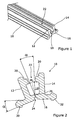
- Figure 1 shows an elongate body or rail 10 for use in the manufacture of a guide rail for a zip-like guided screen (not shown).
- the elongate body 10 includes a pair of spaced-apart walls 12,14 upstanding from a base portion 16.
- the pair of spaced-apart walls 12,14 (which are inclined away from each other, with the angular separation being about 20°) define therebetween an open channel 18.
- Each wall 12,14 has a flange 20 projecting laterally into the channel 18 to define a neck region 22 which has an initial minimum width W 1 of about 2.0mm.
- the base portion 16 includes a groove 24 extending in a notional plane midway between the pair of spaced-apart side walls 12,14.
- the groove 24 provides a line of weakness in the base portion 16, defining a hinge region 26 adjacent the groove 24 in the base portion 16.
- Such an elongate body 10 is readily formed in aluminium using a conventional extrusion process.
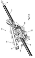
- Figures 3A, 3B, 4A and 4B show the elongate body 10 after it has been plastically deformed to narrow the width of the neck region 22 from the initial width W 1 to a reduced width W 2 .
- one part 30 of the elongate body 10 on one side of the hinge region 26 rotates permanently through an angle ( ⁇ ), which may for example be about 20°, relative to another part 32 of the elongate body 10 on the opposite side of the hinge region 26.
- the walls 12,14 define a keyway 40 for receiving a zip-like retention device, the keyway having a profile configured to allow the zip-like retention device to slide in a first direction Y along the channel 18, and to resist movement in a second direction Z perpendicular to the first direction which would separate the zip-like retention device from the elongate body 10.
- the angle ( ⁇ ) that the one part 30 is rotated relative to the other part 32 is about 20°
- the reduced width W 2 is about 0.6mm, which means the resulting keyway 40 is suitable for use with relatively fine half zippers (i.e. half zippers with teeth less than 1mm thick).
- rails having differing neck widths can be produced from the same extrusion 10.
- the angle ( ⁇ ) that the one part 30 is rotated relative to the other part 32 is about 18°
- the reduced width W 2 is about 0.8mm, which means the resulting keyway 40 is suitable for use with relatively coarse half zippers (i.e. half zippers with teeth at least 1mm thick.
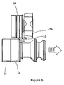
- FIG. 5 illustrates schematically a roller jig 50 for width reduction of the neck region 22 of the channel 18.
- the roller jig 50 comprises two sets of rollers 52,54 which are spaced apart and define a passageway therebetween. At least one set of the rollers 52,54 is actively rotated (e.g. by drive spindle 55) to drive the elongate body 10 through the roller jig 50, and at least one set of the rollers 52,54 is resiliently biased towards the other set to exert a clamping force therebetween.
- the rollers 52,54 engage and support a portion of the elongate body 10 including the wall 12.
- a set of press rollers 56 are urged against another portion of the elongate body including the wall 14 to deform the elongate body 10 in order to reduce the width of the neck region 22 of the channel 18.
- the set of press rollers 56 are mounted on an arm 58 which is pivoted at one end which is downstream of the sets of rollers 52,54.
- An adjustable stop 60 is provided to limit the inclination of arm 58 relative to the sets of rollers 52,54, and hence control the extent of deformation in the elongate member 10. By changing the position of the adjustable stop 60, the roller jig 50 can be controlled so that the width W 2 of the neck region 22 is reduced to the required dimension.
- the roller jig 50 is provided with interchangeable rollers 52, 54 to accommodate elongate bodies with different cross-sections.
Landscapes
- Engineering & Computer Science (AREA)
- Structural Engineering (AREA)
- Architecture (AREA)
- Civil Engineering (AREA)
- Mechanical Engineering (AREA)
- Operating, Guiding And Securing Of Roll- Type Closing Members (AREA)
- Support Devices For Sliding Doors (AREA)
Description
- The present invention relates generally to guided screen systems of the kind employing a screen with a zip-like retention device on each lateral side thereof, and particularly but not exclusively to a method of manufacturing a rail for guiding one lateral side of a screen with a zip-like retention device.
- Each guided screen system comprises a roller blind and a pair of guide rails disposed on either side of an aperture to be screened. The roller blind comprises a roller with a blind fabric wound therearound. The blind fabric has flexible strips on its lateral sides which are trapped within, but free to slide along, a specially shaped groove or keyway in each of the rails. With such a configuration, the blind fabric is held laterally between the rails as it is deployed from the roller.
US 4638844 andGB 2235005 WO2009/098433 discloses a current form of such a screen system. Each flexible strip typically is one half of a zipper, but could be manufactured by moulding a soft or semi-rigid high polymer such as hot-melt synthetic resin or rubber. The important point is that each flexible strip has or forms an enlarged head region (at least in use) which slides along the keyway, but resists being pulled transversely out of the keyway. Such a flexible strip is hereinafter referred to as a zip-like retention device or simply "half zipper", and a roller blind with such flexible strips for engaging corresponding rails is hereinafter referred to as a zip-like guided screen, regardless of whether one half of a zipper is actually used. - Conventional zip-like guided screens typically have relatively coarse half zippers for engaging the rail keyways (i.e. half zippers with teeth at least 1.5mm thick). Such relatively coarse half zippers may be securely retained in appropriately sized rail keyways, sufficient at least for most internal installations. However, such relatively coarse half zippers are often thicker than the blind fabric, and this can lead to a number of problems. For example, when wound onto the roller, the half zippers take up more room in a radial direction than the blind fabric, thereby necessitating the use of bigger housings than would be required to fit the blind fabric alone. Also, when winding the blind fabric onto its roller, there is a tendency for the half zippers to spiral with an axial spread, rather than in a single plane, which conflicts with the aim of retaining the blind fabric between the rails. When the blind fabric and half zipper spirals to one side, the blind fabric is tilted to that one side which may cause the weight bar on the bottom of the blind fabric (hem bar) to tilt meaning it is no longer level. If the spiral abuts an adjacent surface, the blind fabric may then start to spiral in the opposite direction, so tilting the blind fabric and hem bar in a counter direction. This cycle repeats until the blind is fully raised.
- The blinds of such conventional zip-like guided screens also suffer from wrinkling at the edge, where the half zipper is welded/attached to the blind fabric. This wrinkling is caused by the difference in blind build-up on the roller between the single thickness of the blind fabric (between the half zippers) and the greater thickness of the half zippers at the edges. The differences in thickness cause stretching of the blind fabric at the edges which is seen as wrinkling when the blind is deployed. In a similar way, there is a difference in blind build-up diameter between the blind fabric in the middle and the half zippers at the edge, causing stress in the blind fabric when wound on the roller between the tight roll at the edges (because of the thickness of the half zippers) and the loose roll in the middle (between the between the half zippers). Such stress may cause creasing in the blind fabric on the roller, particularly when relatively thin blind fabrics are used and with larger blinds.
- In an attempt to overcome some of the problems of relatively coarse half zippers, the use of relatively fine half zippers (i.e. half zippers with teeth less than 1.5mm thick) has been contemplated. However, even when such relatively fine half zippers are used with rails with correspondingly sized keyways, there is a tendency for the blind fabric to pull all too easily its relatively fine half zippers away from the rails. This tendency remains even when the keyway was lined with specially shaped inserts. Hence, the relatively fine half zippers are considered to provide insufficient anchorage in their respective rail keyways.
-
EP2335956 discloses a screen with zip-like guiding and holding elements on each lateral side thereof for movement along respective slots formed in a pair of opposed guiding rails. Each guiding rail comprises an outer part of aluminium and an inner part of extruded plastics material. The outer part has a substantially "U'-shaped cross-section, and the inner part has a substantially "C"-shaped cross-section. The inner part is resiliently compressed and retained in the outer part to form a keyway with a narrow slot for engaging the zip-like guiding and holding elements. - The present applicant has sought to provide an improved method of manufacturing the rail in order to reduce the tendency for a screen with a zip-like retention device to pull out from its keyway.
- In accordance with a first aspect of the present invention, there is provided a method of manufacturing a guide rail for a zip-like guided screen, comprising: providing an elongate body including a pair of spaced-apart walls defining a channel therebetween, each wall having a flange projecting laterally into the channel to define a neck region of the channel; and plastically deforming the elongate body to reduce the neck region of the channel from a first width to a second width such that the channel defines a keyway for receiving a zip-like retention device, the keyway having a profile which is maintained on completion of the plastic deformation and configured to allow the zip-like retention device to slide in a first direction along the channel, and to resist movement in a second direction perpendicular to the first direction which would separate the zip-like retention device from the elongate body.
- The present applicant has appreciated that, with such a two-step process, it is possible to control very precisely the dimensions of the neck region of the channel in the resulting guide rail, without increasing costs substantially. Such precision may be difficult to achieve economically when manufacturing a guide rail in a conventional manner, for example by extrusion alone.
- The first width may be at least 1.0mm, perhaps even about 2.0mm. The second width may be less than 1.0mm, and may even be 0.8mm or less, such as 0.6mm. In this way, it is possible to manufacture commercially guide rails for use with relatively coarse half zippers and even relatively fine half zippers.
- The elongate body may have a base portion supporting the pair of spaced-apart walls, the base portion having a line of weakness which defines a hinge region when deforming the elongate body to reduce the neck region of the channel from the first width to the second width. The line of weakness may lie in a plane midway between the pair of spaced-apart walls. In this way, one part of the elongate body on one side of the line of weakness may rotate relative to another part of the elongate body on an opposite side of the line of weakness when deforming the elongate body. For example, one part may rotate relative to the other part through an angle of at least 10 degrees, perhaps even at least 15 degrees, for example about 20 degrees.
- The amount of plastic deformation between successive elongate bodies may be varied so as to manufacture bodies having differing second widths.
- The elongate body may be formed from a metal, such as aluminium. The step of providing an elongate body may comprise the step of extruding the elongate body.
- In the method, deforming the elongate body may comprise passing the elongate body through a roller jig, the roller jig having roller means to clamp a first part of the elongate body and at least one press roller to urge a second part of the elongate body against the first part when reducing the neck region of the channel from the first width to the second width. The roller jig may further comprise a stop member for limiting position of the at least one press roller to control width reduction of the neck region.
- The resulting guide rail may be used in a screen system, such as those disclosed in
US 4638844 ,GB 2235005 WO2009/098433 (the contents of which are herein incorporated by reference), where the guide rail is resiliently mounted in a support frame to help maintain tension in the blind fabric during deployment. Thus, the present invention also extends to a method of fabricating a screen system, comprising: resiliently mounting in a support frame a guide rail manufactured in accordance with the first aspect of the present invention; and providing a roller blind comprising a roller with a blind fabric wound therearound, the blind fabric having a zip-like retention device on one lateral side thereof which is configured to slide along the channel in the guide rail in an axial direction and resist being pulled out of the channel in a direction transverse to the axial direction as the blind fabric is deployed from the roller. Resiliently mounting the guide rail in the support frame helps to maintain tension in the blind fabric during deployment when the support frame is secured to a surface such as a wall surrounding a window or door. - An embodiment of the invention will now be described with reference to the accompanying drawings in which:
-
Figure 1 shows a perspective view of an elongate body for use in the manufacture of a guide rail for a zip-like guided screen, in accordance with one embodiment of the present invention; -
Figure 2 is a cross-sectional view of the elongate body ofFigure 1 ; -
Figures 3A and 3B show respectively perspective and cross-sectional views of the elongate body ofFigure 1 once deformed into a one type of guide rail; -
Figures 4A and 4B show respectively perspective and cross-sectional views of the elongate body ofFigure 1 once deformed into another type of guide rail; -
Figure 5 shows a schematic, partially exploded view of a roller jig for deforming the elongate body ofFigure 1 ; and -
Figure 6 shows an end view of the roller jig ofFigure 5 . -
Figure 1 shows an elongate body orrail 10 for use in the manufacture of a guide rail for a zip-like guided screen (not shown). Theelongate body 10 includes a pair of spaced-apart walls base portion 16. The pair of spaced-apart walls 12,14 (which are inclined away from each other, with the angular separation being about 20°) define therebetween anopen channel 18. Eachwall flange 20 projecting laterally into thechannel 18 to define aneck region 22 which has an initial minimum width W1 of about 2.0mm. Thebase portion 16 includes agroove 24 extending in a notional plane midway between the pair of spaced-apartside walls groove 24 provides a line of weakness in thebase portion 16, defining ahinge region 26 adjacent thegroove 24 in thebase portion 16. Such anelongate body 10 is readily formed in aluminium using a conventional extrusion process. -
Figures 3A, 3B, 4A and 4B show theelongate body 10 after it has been plastically deformed to narrow the width of theneck region 22 from the initial width W1 to a reduced width W2. During deformation, onepart 30 of theelongate body 10 on one side of thehinge region 26 rotates permanently through an angle (α), which may for example be about 20°, relative to anotherpart 32 of theelongate body 10 on the opposite side of thehinge region 26. Once theelongate body 10 has been deformed, thewalls keyway 40 for receiving a zip-like retention device, the keyway having a profile configured to allow the zip-like retention device to slide in a first direction Y along thechannel 18, and to resist movement in a second direction Z perpendicular to the first direction which would separate the zip-like retention device from theelongate body 10. InFigures 3A and 3B , the angle (α) that the onepart 30 is rotated relative to theother part 32 is about 20°, and the reduced width W2 is about 0.6mm, which means the resultingkeyway 40 is suitable for use with relatively fine half zippers (i.e. half zippers with teeth less than 1mm thick). - Moreover, by varying the amount of plastic deformation, rails having differing neck widths can be produced from the
same extrusion 10. Thus, as shown infigures 4A and 4B , the angle (α) that the onepart 30 is rotated relative to theother part 32 is about 18°, and the reduced width W2 is about 0.8mm, which means the resultingkeyway 40 is suitable for use with relatively coarse half zippers (i.e. half zippers with teeth at least 1mm thick. - One way of deforming the
elongate body 10 to achieve the aforementioned reduction in theneck region 22 of thechannel 18 will now be described by way of example with reference toFigures 5 and6 .Figure 5 illustrates schematically aroller jig 50 for width reduction of theneck region 22 of thechannel 18. Theroller jig 50 comprises two sets ofrollers rollers elongate body 10 through theroller jig 50, and at least one set of therollers elongate body 10 is driven in direction X through the passageway of theroller jig 50, therollers elongate body 10 including thewall 12. At the same time, a set ofpress rollers 56 are urged against another portion of the elongate body including thewall 14 to deform theelongate body 10 in order to reduce the width of theneck region 22 of thechannel 18. The set ofpress rollers 56 are mounted on anarm 58 which is pivoted at one end which is downstream of the sets ofrollers adjustable stop 60 is provided to limit the inclination ofarm 58 relative to the sets ofrollers elongate member 10. By changing the position of theadjustable stop 60, theroller jig 50 can be controlled so that the width W2 of theneck region 22 is reduced to the required dimension. - The
roller jig 50 is provided withinterchangeable rollers
Claims (11)
- A method of manufacturing a guide rail for a zip-like guided screen, comprising:providing an elongate body (10) including a pair of spaced-apart walls (12,14) defining a channel (18) therebetween, each wall (12,14) having a flange (20) projecting laterally into the channel (18) to define a neck region (22) of the channel; characterized by:plastically deforming the elongate body (10) to reduce the neck region (22) of the channel (18) from a first width to a second width such that the channel defines a keyway (40) for receiving a zip-like retention device, the keyway (40) having a profile which is maintained on completion of the plastic deformation and is configured to allow the zip-like retention device to slide in a first direction along the channel (18), and to resist movement in a second direction perpendicular to the first direction which would separate the zip-like retention device from the elongate body (10).
- A method according to claim 1, in which the first width is at least 1.0mm.
- A method according to claim 1 or claim 2, in which the second width is less than 1.0mm.
- A method according to any one of the preceding claims, in which the elongate body (10) has a base portion (16) supporting the pair of spaced-apart walls (12,14), with the base portion (16) having a line of weakness (24) which defines a hinge region (26) when deforming the elongate body (10) to reduce the neck region (22) of the channel (18) from the first width to the second width.
- A method according to claim 4, in which one part of the elongate body (10) on one side of the line of weakness (24) rotates through an angle of at least 10 degrees relative to another part of the elongate body (10) on an opposite side of the line of weakness (24) when deforming the elongate body (10).
- A method according to any preceding claim and comprising the step of providing successive elongate bodies and varying the amount of plastic deformation between successive bodies so as to manufacture bodies having differing second widths.
- A method according to any one of the preceding claims, in which the elongate body (10) is formed from a metal, such as aluminium.
- A method according to any one of the preceding claims, in which the step of providing an elongate body (10) comprises the step of extruding the elongate body.
- A method according to any one of the preceding claims, in which deforming the elongate body comprises passing the elongate body (10) through a roller jig (50), the roller jig having roller means (52,54) to clamp a first part of the elongate body and at least one press roller (56) to urge a second part of the elongate body (10) against the first part when reducing the neck region (22) of the channel (18) from the first width to the second width.
- A method according to claim 9, in which the roller jig (50) further comprises a stop member (60) for limiting position of the at least one press roller (56) to control width reduction of the neck region.
- A method of fabricating a screen system, comprising:resiliently mounting in a support frame a guide rail manufactured in accordance with any one of claims 1-10; andproviding a roller blind comprising a roller with a blind fabric wound therearound, the blind fabric having a zip-like retention device on one lateral side thereof which is configured to slide along the channel in the guide rail in an axial direction and resist being pulled out of the channel in a direction transverse to the axial direction as the blind fabric is deployed from the roller.
Applications Claiming Priority (2)
| Application Number | Priority Date | Filing Date | Title |
|---|---|---|---|
| GB1320553.9A GB2520505A (en) | 2013-11-21 | 2013-11-21 | Rail for guided screen system |
| PCT/GB2014/053292 WO2015075422A1 (en) | 2013-11-21 | 2014-11-05 | Method of manufacturing a guide rail for a screen |
Publications (2)
| Publication Number | Publication Date |
|---|---|
| EP2904182A1 EP2904182A1 (en) | 2015-08-12 |
| EP2904182B1 true EP2904182B1 (en) | 2016-09-28 |
Family
ID=49917977
Family Applications (1)
| Application Number | Title | Priority Date | Filing Date |
|---|---|---|---|
| EP14809952.6A Active EP2904182B1 (en) | 2013-11-21 | 2014-11-05 | Method of manufacturing a guide rail for a screen |
Country Status (7)
| Country | Link |
|---|---|
| US (1) | US20160023258A1 (en) |
| EP (1) | EP2904182B1 (en) |
| JP (1) | JP2016537541A (en) |
| AU (1) | AU2014324170A1 (en) |
| ES (1) | ES2604660T3 (en) |
| GB (1) | GB2520505A (en) |
| WO (1) | WO2015075422A1 (en) |
Families Citing this family (5)
| Publication number | Priority date | Publication date | Assignee | Title |
|---|---|---|---|---|
| EP4035655A1 (en) | 2021-02-01 | 2022-08-03 | Oxford University Innovation Limited | Immune modulating particles |
| EP4035673A1 (en) | 2021-02-01 | 2022-08-03 | Oxford University Innovation Limited | Transdermal vaccine |
| EP4036581A1 (en) | 2021-02-01 | 2022-08-03 | Oxford University Innovation Limited | Cavitation agent |
| EP4036580A1 (en) | 2021-02-01 | 2022-08-03 | Oxford University Innovation Limited | Drug loaded cavitation agent |
| CN114290011B (en) * | 2021-12-31 | 2024-04-09 | 江苏金荣森制冷科技有限公司 | Forming device |
Family Cites Families (12)
| Publication number | Priority date | Publication date | Assignee | Title |
|---|---|---|---|---|
| US4458739A (en) * | 1980-01-08 | 1984-07-10 | Murray John J | Insulative roll-up shade system |
| US4428218A (en) * | 1981-11-24 | 1984-01-31 | Larocca Joseph M | Method of manufacture and assembly of extruded aluminum salt for roller shutter |
| JPS61263733A (en) * | 1985-05-17 | 1986-11-21 | Sanwa Shutter Corp | Manufacture of guide rail in shutter |
| NO165693C (en) * | 1988-11-23 | 1991-03-20 | Spilka Inco Ltd As | PROCEDURE FOR THE MANUFACTURING OF SLIDE HINGED WINDOWS. . |
| US6038825A (en) * | 1996-02-21 | 2000-03-21 | The Lockformer Company | Insulated glass window spacer and method for making window spacer |
| FI965070A0 (en) * | 1996-12-17 | 1996-12-17 | Samesor Smt International Oy | In this case, the roll forming of the left metal product is rolled |
| AU752127B2 (en) * | 1999-04-14 | 2002-09-05 | Hunter Douglas Industries Bv | Side guide for a roller covering |
| US8453485B2 (en) * | 2004-02-17 | 2013-06-04 | The Bradbury Company, Inc. | Methods and apparatus for controlling flare in roll-forming processes |
| GB0802263D0 (en) * | 2008-02-07 | 2008-03-12 | Dibben Martin | Zip screen system |
| GB2466780A (en) * | 2009-01-03 | 2010-07-07 | Anthony William Dee | Mechanism for sealing edges of a roller blind |
| FR2953768B1 (en) * | 2009-12-15 | 2012-11-23 | Acs France Sas | OCCULTATION DEVICE, VEHICLE AND METHOD OF MANUFACTURING THE SAME |
| CN202325184U (en) * | 2011-11-18 | 2012-07-11 | 宜智达节能科技(苏州)有限公司 | Windproof track used in outdoor roller blind |
-
2013
- 2013-11-21 GB GB1320553.9A patent/GB2520505A/en not_active Withdrawn
-
2014
- 2014-11-05 ES ES14809952.6T patent/ES2604660T3/en active Active
- 2014-11-05 WO PCT/GB2014/053292 patent/WO2015075422A1/en active Application Filing
- 2014-11-05 JP JP2016554923A patent/JP2016537541A/en active Pending
- 2014-11-05 AU AU2014324170A patent/AU2014324170A1/en not_active Abandoned
- 2014-11-05 US US14/432,459 patent/US20160023258A1/en not_active Abandoned
- 2014-11-05 EP EP14809952.6A patent/EP2904182B1/en active Active
Non-Patent Citations (1)
| Title |
|---|
| None * |
Also Published As
| Publication number | Publication date |
|---|---|
| WO2015075422A1 (en) | 2015-05-28 |
| EP2904182A1 (en) | 2015-08-12 |
| JP2016537541A (en) | 2016-12-01 |
| ES2604660T3 (en) | 2017-03-08 |
| AU2014324170A1 (en) | 2015-06-04 |
| US20160023258A1 (en) | 2016-01-28 |
| GB201320553D0 (en) | 2014-01-08 |
| GB2520505A (en) | 2015-05-27 |
Similar Documents
| Publication | Publication Date | Title |
|---|---|---|
| EP2904182B1 (en) | Method of manufacturing a guide rail for a screen | |
| US20230272669A1 (en) | Window treatment hembar | |
| CA2046377C (en) | Method and apparatus for mounting a retractable window covering | |
| JP3163685U (en) | Blind system | |
| EP3130742B1 (en) | Screen device | |
| US20120325416A1 (en) | Roll screen device | |
| EP3130741B1 (en) | Screen apparatus and method for manufacturing the same | |
| EP2238309A1 (en) | Screen system with a bracket for mounting a guiding rail | |
| JP2005530062A (en) | Shutter device having flexible side edges | |
| US20170247941A1 (en) | Roll-up coverings for architectural openings and related methods, systems and devices | |
| EP3163006A1 (en) | Roller blind | |
| EP2256283B1 (en) | Bottom bar for a blind assembly | |
| EP2703595A2 (en) | Tilting roller blind with guides, especially for roof windows | |
| EP3409873A1 (en) | Tension cord mounting for an architectural covering | |
| EP3363986A1 (en) | Handling system for mobile screen curtains | |
| GB2503934A (en) | Guide rail with reinforcing member for a window screen | |
| JP2017044046A (en) | Roll screen | |
| KR101886121B1 (en) | Guide apparatus for screen and blind comprising the same | |
| US20200399957A1 (en) | Adjustable width roller blind assembly | |
| JP3598497B2 (en) | Shutter device | |
| GB2534891A (en) | Apparatus and method for mounting a display sheet | |
| EP2140148B1 (en) | A method for fastening a screening body to a bottom element in a screening arrangement | |
| JP3177900U (en) | Winding deviation adjustment mechanism of solar radiation shielding device | |
| WO2014122504A1 (en) | Plastic profile for a rigid frame | |
| JP2015078559A (en) | Roll-up horizontal blind |
Legal Events
| Date | Code | Title | Description |
|---|---|---|---|
| PUAI | Public reference made under article 153(3) epc to a published international application that has entered the european phase |
Free format text: ORIGINAL CODE: 0009012 |
|
| 17P | Request for examination filed |
Effective date: 20150420 |
|
| AK | Designated contracting states |
Kind code of ref document: A1 Designated state(s): AL AT BE BG CH CY CZ DE DK EE ES FI FR GB GR HR HU IE IS IT LI LT LU LV MC MK MT NL NO PL PT RO RS SE SI SK SM TR |
|
| AX | Request for extension of the european patent |
Extension state: BA ME |
|
| GRAJ | Information related to disapproval of communication of intention to grant by the applicant or resumption of examination proceedings by the epo deleted |
Free format text: ORIGINAL CODE: EPIDOSDIGR1 |
|
| GRAP | Despatch of communication of intention to grant a patent |
Free format text: ORIGINAL CODE: EPIDOSNIGR1 |
|
| DAX | Request for extension of the european patent (deleted) | ||
| INTG | Intention to grant announced |
Effective date: 20160718 |
|
| GRAS | Grant fee paid |
Free format text: ORIGINAL CODE: EPIDOSNIGR3 |
|
| GRAA | (expected) grant |
Free format text: ORIGINAL CODE: 0009210 |
|
| AK | Designated contracting states |
Kind code of ref document: B1 Designated state(s): AL AT BE BG CH CY CZ DE DK EE ES FI FR GB GR HR HU IE IS IT LI LT LU LV MC MK MT NL NO PL PT RO RS SE SI SK SM TR |
|
| REG | Reference to a national code |
Ref country code: GB Ref legal event code: FG4D |
|
| REG | Reference to a national code |
Ref country code: CH Ref legal event code: EP |
|
| REG | Reference to a national code |
Ref country code: AT Ref legal event code: REF Ref document number: 832928 Country of ref document: AT Kind code of ref document: T Effective date: 20161015 |
|
| REG | Reference to a national code |
Ref country code: IE Ref legal event code: FG4D |
|
| REG | Reference to a national code |
Ref country code: FR Ref legal event code: PLFP Year of fee payment: 3 |
|
| REG | Reference to a national code |
Ref country code: DE Ref legal event code: R096 Ref document number: 602014004009 Country of ref document: DE |
|
| REG | Reference to a national code |
Ref country code: LT Ref legal event code: MG4D |
|
| PG25 | Lapsed in a contracting state [announced via postgrant information from national office to epo] |
Ref country code: HR Free format text: LAPSE BECAUSE OF FAILURE TO SUBMIT A TRANSLATION OF THE DESCRIPTION OR TO PAY THE FEE WITHIN THE PRESCRIBED TIME-LIMIT Effective date: 20160928 Ref country code: NO Free format text: LAPSE BECAUSE OF FAILURE TO SUBMIT A TRANSLATION OF THE DESCRIPTION OR TO PAY THE FEE WITHIN THE PRESCRIBED TIME-LIMIT Effective date: 20161228 Ref country code: RS Free format text: LAPSE BECAUSE OF FAILURE TO SUBMIT A TRANSLATION OF THE DESCRIPTION OR TO PAY THE FEE WITHIN THE PRESCRIBED TIME-LIMIT Effective date: 20160928 Ref country code: LT Free format text: LAPSE BECAUSE OF FAILURE TO SUBMIT A TRANSLATION OF THE DESCRIPTION OR TO PAY THE FEE WITHIN THE PRESCRIBED TIME-LIMIT Effective date: 20160928 Ref country code: FI Free format text: LAPSE BECAUSE OF FAILURE TO SUBMIT A TRANSLATION OF THE DESCRIPTION OR TO PAY THE FEE WITHIN THE PRESCRIBED TIME-LIMIT Effective date: 20160928 |
|
| REG | Reference to a national code |
Ref country code: NL Ref legal event code: MP Effective date: 20160928 |
|
| REG | Reference to a national code |
Ref country code: AT Ref legal event code: MK05 Ref document number: 832928 Country of ref document: AT Kind code of ref document: T Effective date: 20160928 |
|
| PG25 | Lapsed in a contracting state [announced via postgrant information from national office to epo] |
Ref country code: NL Free format text: LAPSE BECAUSE OF FAILURE TO SUBMIT A TRANSLATION OF THE DESCRIPTION OR TO PAY THE FEE WITHIN THE PRESCRIBED TIME-LIMIT Effective date: 20160928 Ref country code: LV Free format text: LAPSE BECAUSE OF FAILURE TO SUBMIT A TRANSLATION OF THE DESCRIPTION OR TO PAY THE FEE WITHIN THE PRESCRIBED TIME-LIMIT Effective date: 20160928 Ref country code: GR Free format text: LAPSE BECAUSE OF FAILURE TO SUBMIT A TRANSLATION OF THE DESCRIPTION OR TO PAY THE FEE WITHIN THE PRESCRIBED TIME-LIMIT Effective date: 20161229 Ref country code: SE Free format text: LAPSE BECAUSE OF FAILURE TO SUBMIT A TRANSLATION OF THE DESCRIPTION OR TO PAY THE FEE WITHIN THE PRESCRIBED TIME-LIMIT Effective date: 20160928 Ref country code: BE Free format text: LAPSE BECAUSE OF NON-PAYMENT OF DUE FEES Effective date: 20161130 |
|
| REG | Reference to a national code |
Ref country code: ES Ref legal event code: FG2A Ref document number: 2604660 Country of ref document: ES Kind code of ref document: T3 Effective date: 20170308 |
|
| PG25 | Lapsed in a contracting state [announced via postgrant information from national office to epo] |
Ref country code: RO Free format text: LAPSE BECAUSE OF FAILURE TO SUBMIT A TRANSLATION OF THE DESCRIPTION OR TO PAY THE FEE WITHIN THE PRESCRIBED TIME-LIMIT Effective date: 20160928 Ref country code: EE Free format text: LAPSE BECAUSE OF FAILURE TO SUBMIT A TRANSLATION OF THE DESCRIPTION OR TO PAY THE FEE WITHIN THE PRESCRIBED TIME-LIMIT Effective date: 20160928 |
|
| PG25 | Lapsed in a contracting state [announced via postgrant information from national office to epo] |
Ref country code: PL Free format text: LAPSE BECAUSE OF FAILURE TO SUBMIT A TRANSLATION OF THE DESCRIPTION OR TO PAY THE FEE WITHIN THE PRESCRIBED TIME-LIMIT Effective date: 20160928 Ref country code: AT Free format text: LAPSE BECAUSE OF FAILURE TO SUBMIT A TRANSLATION OF THE DESCRIPTION OR TO PAY THE FEE WITHIN THE PRESCRIBED TIME-LIMIT Effective date: 20160928 Ref country code: BE Free format text: LAPSE BECAUSE OF FAILURE TO SUBMIT A TRANSLATION OF THE DESCRIPTION OR TO PAY THE FEE WITHIN THE PRESCRIBED TIME-LIMIT Effective date: 20160928 Ref country code: SK Free format text: LAPSE BECAUSE OF FAILURE TO SUBMIT A TRANSLATION OF THE DESCRIPTION OR TO PAY THE FEE WITHIN THE PRESCRIBED TIME-LIMIT Effective date: 20160928 Ref country code: BG Free format text: LAPSE BECAUSE OF FAILURE TO SUBMIT A TRANSLATION OF THE DESCRIPTION OR TO PAY THE FEE WITHIN THE PRESCRIBED TIME-LIMIT Effective date: 20161228 Ref country code: SM Free format text: LAPSE BECAUSE OF FAILURE TO SUBMIT A TRANSLATION OF THE DESCRIPTION OR TO PAY THE FEE WITHIN THE PRESCRIBED TIME-LIMIT Effective date: 20160928 Ref country code: CZ Free format text: LAPSE BECAUSE OF FAILURE TO SUBMIT A TRANSLATION OF THE DESCRIPTION OR TO PAY THE FEE WITHIN THE PRESCRIBED TIME-LIMIT Effective date: 20160928 Ref country code: IS Free format text: LAPSE BECAUSE OF FAILURE TO SUBMIT A TRANSLATION OF THE DESCRIPTION OR TO PAY THE FEE WITHIN THE PRESCRIBED TIME-LIMIT Effective date: 20170128 Ref country code: PT Free format text: LAPSE BECAUSE OF FAILURE TO SUBMIT A TRANSLATION OF THE DESCRIPTION OR TO PAY THE FEE WITHIN THE PRESCRIBED TIME-LIMIT Effective date: 20170130 |
|
| REG | Reference to a national code |
Ref country code: DE Ref legal event code: R097 Ref document number: 602014004009 Country of ref document: DE |
|
| PG25 | Lapsed in a contracting state [announced via postgrant information from national office to epo] |
Ref country code: DK Free format text: LAPSE BECAUSE OF FAILURE TO SUBMIT A TRANSLATION OF THE DESCRIPTION OR TO PAY THE FEE WITHIN THE PRESCRIBED TIME-LIMIT Effective date: 20160928 |
|
| PLBE | No opposition filed within time limit |
Free format text: ORIGINAL CODE: 0009261 |
|
| STAA | Information on the status of an ep patent application or granted ep patent |
Free format text: STATUS: NO OPPOSITION FILED WITHIN TIME LIMIT |
|
| REG | Reference to a national code |
Ref country code: IE Ref legal event code: MM4A |
|
| 26N | No opposition filed |
Effective date: 20170629 |
|
| PG25 | Lapsed in a contracting state [announced via postgrant information from national office to epo] |
Ref country code: LU Free format text: LAPSE BECAUSE OF NON-PAYMENT OF DUE FEES Effective date: 20161130 |
|
| REG | Reference to a national code |
Ref country code: FR Ref legal event code: PLFP Year of fee payment: 4 |
|
| PG25 | Lapsed in a contracting state [announced via postgrant information from national office to epo] |
Ref country code: IE Free format text: LAPSE BECAUSE OF NON-PAYMENT OF DUE FEES Effective date: 20161105 Ref country code: SI Free format text: LAPSE BECAUSE OF FAILURE TO SUBMIT A TRANSLATION OF THE DESCRIPTION OR TO PAY THE FEE WITHIN THE PRESCRIBED TIME-LIMIT Effective date: 20160928 |
|
| PG25 | Lapsed in a contracting state [announced via postgrant information from national office to epo] |
Ref country code: HU Free format text: LAPSE BECAUSE OF FAILURE TO SUBMIT A TRANSLATION OF THE DESCRIPTION OR TO PAY THE FEE WITHIN THE PRESCRIBED TIME-LIMIT; INVALID AB INITIO Effective date: 20141105 |
|
| PG25 | Lapsed in a contracting state [announced via postgrant information from national office to epo] |
Ref country code: MK Free format text: LAPSE BECAUSE OF FAILURE TO SUBMIT A TRANSLATION OF THE DESCRIPTION OR TO PAY THE FEE WITHIN THE PRESCRIBED TIME-LIMIT Effective date: 20160928 Ref country code: MC Free format text: LAPSE BECAUSE OF FAILURE TO SUBMIT A TRANSLATION OF THE DESCRIPTION OR TO PAY THE FEE WITHIN THE PRESCRIBED TIME-LIMIT Effective date: 20160928 Ref country code: CY Free format text: LAPSE BECAUSE OF FAILURE TO SUBMIT A TRANSLATION OF THE DESCRIPTION OR TO PAY THE FEE WITHIN THE PRESCRIBED TIME-LIMIT Effective date: 20160928 |
|
| PG25 | Lapsed in a contracting state [announced via postgrant information from national office to epo] |
Ref country code: CH Free format text: LAPSE BECAUSE OF NON-PAYMENT OF DUE FEES Effective date: 20171130 Ref country code: LI Free format text: LAPSE BECAUSE OF NON-PAYMENT OF DUE FEES Effective date: 20171130 |
|
| PG25 | Lapsed in a contracting state [announced via postgrant information from national office to epo] |
Ref country code: MT Free format text: LAPSE BECAUSE OF NON-PAYMENT OF DUE FEES Effective date: 20161105 |
|
| PG25 | Lapsed in a contracting state [announced via postgrant information from national office to epo] |
Ref country code: TR Free format text: LAPSE BECAUSE OF FAILURE TO SUBMIT A TRANSLATION OF THE DESCRIPTION OR TO PAY THE FEE WITHIN THE PRESCRIBED TIME-LIMIT Effective date: 20160928 Ref country code: AL Free format text: LAPSE BECAUSE OF FAILURE TO SUBMIT A TRANSLATION OF THE DESCRIPTION OR TO PAY THE FEE WITHIN THE PRESCRIBED TIME-LIMIT Effective date: 20160928 |
|
| PGFP | Annual fee paid to national office [announced via postgrant information from national office to epo] |
Ref country code: GB Payment date: 20231101 Year of fee payment: 10 |
|
| PGFP | Annual fee paid to national office [announced via postgrant information from national office to epo] |
Ref country code: ES Payment date: 20231201 Year of fee payment: 10 |
|
| PGFP | Annual fee paid to national office [announced via postgrant information from national office to epo] |
Ref country code: IT Payment date: 20231106 Year of fee payment: 10 Ref country code: FR Payment date: 20231106 Year of fee payment: 10 Ref country code: DE Payment date: 20231110 Year of fee payment: 10 |