EP2903664B1 - Injection device with dosing control means - Google Patents
Injection device with dosing control means Download PDFInfo
- Publication number
- EP2903664B1 EP2903664B1 EP13727557.4A EP13727557A EP2903664B1 EP 2903664 B1 EP2903664 B1 EP 2903664B1 EP 13727557 A EP13727557 A EP 13727557A EP 2903664 B1 EP2903664 B1 EP 2903664B1
- Authority
- EP
- European Patent Office
- Prior art keywords
- casing
- plunger rod
- injection device
- dosing
- casing part
- Prior art date
- Legal status (The legal status is an assumption and is not a legal conclusion. Google has not performed a legal analysis and makes no representation as to the accuracy of the status listed.)
- Active
Links
Images





Classifications
-
- A—HUMAN NECESSITIES
- A61—MEDICAL OR VETERINARY SCIENCE; HYGIENE
- A61M—DEVICES FOR INTRODUCING MEDIA INTO, OR ONTO, THE BODY; DEVICES FOR TRANSDUCING BODY MEDIA OR FOR TAKING MEDIA FROM THE BODY; DEVICES FOR PRODUCING OR ENDING SLEEP OR STUPOR
- A61M5/00—Devices for bringing media into the body in a subcutaneous, intra-vascular or intramuscular way; Accessories therefor, e.g. filling or cleaning devices, arm rests
- A61M5/178—Syringes
- A61M5/28—Syringe ampoules or carpules, i.e. ampoules or carpules provided with a needle
-
- A—HUMAN NECESSITIES
- A61—MEDICAL OR VETERINARY SCIENCE; HYGIENE
- A61M—DEVICES FOR INTRODUCING MEDIA INTO, OR ONTO, THE BODY; DEVICES FOR TRANSDUCING BODY MEDIA OR FOR TAKING MEDIA FROM THE BODY; DEVICES FOR PRODUCING OR ENDING SLEEP OR STUPOR
- A61M5/00—Devices for bringing media into the body in a subcutaneous, intra-vascular or intramuscular way; Accessories therefor, e.g. filling or cleaning devices, arm rests
- A61M5/178—Syringes
- A61M5/31—Details
- A61M5/315—Pistons; Piston-rods; Guiding, blocking or restricting the movement of the rod or piston; Appliances on the rod for facilitating dosing ; Dosing mechanisms
- A61M5/31533—Dosing mechanisms, i.e. setting a dose
- A61M5/31535—Means improving security or handling thereof, e.g. blocking means, means preventing insufficient dosing, means allowing correction of overset dose
- A61M5/31536—Blocking means to immobilize a selected dose, e.g. to administer equal doses
-
- A—HUMAN NECESSITIES
- A61—MEDICAL OR VETERINARY SCIENCE; HYGIENE
- A61M—DEVICES FOR INTRODUCING MEDIA INTO, OR ONTO, THE BODY; DEVICES FOR TRANSDUCING BODY MEDIA OR FOR TAKING MEDIA FROM THE BODY; DEVICES FOR PRODUCING OR ENDING SLEEP OR STUPOR
- A61M5/00—Devices for bringing media into the body in a subcutaneous, intra-vascular or intramuscular way; Accessories therefor, e.g. filling or cleaning devices, arm rests
- A61M5/178—Syringes
- A61M5/31—Details
- A61M5/3146—Priming, e.g. purging, reducing backlash or clearance
-
- A—HUMAN NECESSITIES
- A61—MEDICAL OR VETERINARY SCIENCE; HYGIENE
- A61M—DEVICES FOR INTRODUCING MEDIA INTO, OR ONTO, THE BODY; DEVICES FOR TRANSDUCING BODY MEDIA OR FOR TAKING MEDIA FROM THE BODY; DEVICES FOR PRODUCING OR ENDING SLEEP OR STUPOR
- A61M5/00—Devices for bringing media into the body in a subcutaneous, intra-vascular or intramuscular way; Accessories therefor, e.g. filling or cleaning devices, arm rests
- A61M5/178—Syringes
- A61M5/31—Details
- A61M5/315—Pistons; Piston-rods; Guiding, blocking or restricting the movement of the rod or piston; Appliances on the rod for facilitating dosing ; Dosing mechanisms
- A61M5/31533—Dosing mechanisms, i.e. setting a dose
- A61M5/31545—Setting modes for dosing
- A61M5/31548—Mechanically operated dose setting member
- A61M5/3155—Mechanically operated dose setting member by rotational movement of dose setting member, e.g. during setting or filling of a syringe
-
- A—HUMAN NECESSITIES
- A61—MEDICAL OR VETERINARY SCIENCE; HYGIENE
- A61M—DEVICES FOR INTRODUCING MEDIA INTO, OR ONTO, THE BODY; DEVICES FOR TRANSDUCING BODY MEDIA OR FOR TAKING MEDIA FROM THE BODY; DEVICES FOR PRODUCING OR ENDING SLEEP OR STUPOR
- A61M5/00—Devices for bringing media into the body in a subcutaneous, intra-vascular or intramuscular way; Accessories therefor, e.g. filling or cleaning devices, arm rests
- A61M5/178—Syringes
- A61M5/31—Details
- A61M5/32—Needles; Details of needles pertaining to their connection with syringe or hub; Accessories for bringing the needle into, or holding the needle on, the body; Devices for protection of needles
- A61M5/3202—Devices for protection of the needle before use, e.g. caps
-
- A—HUMAN NECESSITIES
- A61—MEDICAL OR VETERINARY SCIENCE; HYGIENE
- A61M—DEVICES FOR INTRODUCING MEDIA INTO, OR ONTO, THE BODY; DEVICES FOR TRANSDUCING BODY MEDIA OR FOR TAKING MEDIA FROM THE BODY; DEVICES FOR PRODUCING OR ENDING SLEEP OR STUPOR
- A61M5/00—Devices for bringing media into the body in a subcutaneous, intra-vascular or intramuscular way; Accessories therefor, e.g. filling or cleaning devices, arm rests
- A61M5/178—Syringes
- A61M5/31—Details
- A61M5/32—Needles; Details of needles pertaining to their connection with syringe or hub; Accessories for bringing the needle into, or holding the needle on, the body; Devices for protection of needles
- A61M5/3205—Apparatus for removing or disposing of used needles or syringes, e.g. containers; Means for protection against accidental injuries from used needles
- A61M5/321—Means for protection against accidental injuries by used needles
- A61M5/3243—Means for protection against accidental injuries by used needles being axially-extensible, e.g. protective sleeves coaxially slidable on the syringe barrel
-
- A—HUMAN NECESSITIES
- A61—MEDICAL OR VETERINARY SCIENCE; HYGIENE
- A61M—DEVICES FOR INTRODUCING MEDIA INTO, OR ONTO, THE BODY; DEVICES FOR TRANSDUCING BODY MEDIA OR FOR TAKING MEDIA FROM THE BODY; DEVICES FOR PRODUCING OR ENDING SLEEP OR STUPOR
- A61M5/00—Devices for bringing media into the body in a subcutaneous, intra-vascular or intramuscular way; Accessories therefor, e.g. filling or cleaning devices, arm rests
- A61M5/178—Syringes
- A61M5/31—Details
- A61M5/32—Needles; Details of needles pertaining to their connection with syringe or hub; Accessories for bringing the needle into, or holding the needle on, the body; Devices for protection of needles
- A61M5/3205—Apparatus for removing or disposing of used needles or syringes, e.g. containers; Means for protection against accidental injuries from used needles
- A61M5/321—Means for protection against accidental injuries by used needles
- A61M5/3243—Means for protection against accidental injuries by used needles being axially-extensible, e.g. protective sleeves coaxially slidable on the syringe barrel
- A61M5/326—Fully automatic sleeve extension, i.e. in which triggering of the sleeve does not require a deliberate action by the user
-
- A—HUMAN NECESSITIES
- A61—MEDICAL OR VETERINARY SCIENCE; HYGIENE
- A61M—DEVICES FOR INTRODUCING MEDIA INTO, OR ONTO, THE BODY; DEVICES FOR TRANSDUCING BODY MEDIA OR FOR TAKING MEDIA FROM THE BODY; DEVICES FOR PRODUCING OR ENDING SLEEP OR STUPOR
- A61M5/00—Devices for bringing media into the body in a subcutaneous, intra-vascular or intramuscular way; Accessories therefor, e.g. filling or cleaning devices, arm rests
- A61M5/50—Devices for bringing media into the body in a subcutaneous, intra-vascular or intramuscular way; Accessories therefor, e.g. filling or cleaning devices, arm rests having means for preventing re-use, or for indicating if defective, used, tampered with or unsterile
- A61M5/5013—Means for blocking the piston or the fluid passageway to prevent illegal refilling of a syringe
- A61M5/502—Means for blocking the piston or the fluid passageway to prevent illegal refilling of a syringe for blocking the piston
-
- A—HUMAN NECESSITIES
- A61—MEDICAL OR VETERINARY SCIENCE; HYGIENE
- A61M—DEVICES FOR INTRODUCING MEDIA INTO, OR ONTO, THE BODY; DEVICES FOR TRANSDUCING BODY MEDIA OR FOR TAKING MEDIA FROM THE BODY; DEVICES FOR PRODUCING OR ENDING SLEEP OR STUPOR
- A61M5/00—Devices for bringing media into the body in a subcutaneous, intra-vascular or intramuscular way; Accessories therefor, e.g. filling or cleaning devices, arm rests
- A61M5/178—Syringes
- A61M5/31—Details
- A61M5/3129—Syringe barrels
- A61M2005/3142—Modular constructions, e.g. supplied in separate pieces to be assembled by end-user
-
- A—HUMAN NECESSITIES
- A61—MEDICAL OR VETERINARY SCIENCE; HYGIENE
- A61M—DEVICES FOR INTRODUCING MEDIA INTO, OR ONTO, THE BODY; DEVICES FOR TRANSDUCING BODY MEDIA OR FOR TAKING MEDIA FROM THE BODY; DEVICES FOR PRODUCING OR ENDING SLEEP OR STUPOR
- A61M5/00—Devices for bringing media into the body in a subcutaneous, intra-vascular or intramuscular way; Accessories therefor, e.g. filling or cleaning devices, arm rests
- A61M5/178—Syringes
- A61M5/31—Details
- A61M2005/3143—Damping means for syringe components executing relative movements, e.g. retarders or attenuators slowing down or timing syringe mechanisms
-
- A—HUMAN NECESSITIES
- A61—MEDICAL OR VETERINARY SCIENCE; HYGIENE
- A61M—DEVICES FOR INTRODUCING MEDIA INTO, OR ONTO, THE BODY; DEVICES FOR TRANSDUCING BODY MEDIA OR FOR TAKING MEDIA FROM THE BODY; DEVICES FOR PRODUCING OR ENDING SLEEP OR STUPOR
- A61M5/00—Devices for bringing media into the body in a subcutaneous, intra-vascular or intramuscular way; Accessories therefor, e.g. filling or cleaning devices, arm rests
- A61M5/178—Syringes
- A61M5/31—Details
- A61M5/32—Needles; Details of needles pertaining to their connection with syringe or hub; Accessories for bringing the needle into, or holding the needle on, the body; Devices for protection of needles
- A61M5/3205—Apparatus for removing or disposing of used needles or syringes, e.g. containers; Means for protection against accidental injuries from used needles
- A61M5/321—Means for protection against accidental injuries by used needles
- A61M5/3243—Means for protection against accidental injuries by used needles being axially-extensible, e.g. protective sleeves coaxially slidable on the syringe barrel
- A61M5/3245—Constructional features thereof, e.g. to improve manipulation or functioning
- A61M2005/3247—Means to impede repositioning of protection sleeve from needle covering to needle uncovering position
-
- A—HUMAN NECESSITIES
- A61—MEDICAL OR VETERINARY SCIENCE; HYGIENE
- A61M—DEVICES FOR INTRODUCING MEDIA INTO, OR ONTO, THE BODY; DEVICES FOR TRANSDUCING BODY MEDIA OR FOR TAKING MEDIA FROM THE BODY; DEVICES FOR PRODUCING OR ENDING SLEEP OR STUPOR
- A61M5/00—Devices for bringing media into the body in a subcutaneous, intra-vascular or intramuscular way; Accessories therefor, e.g. filling or cleaning devices, arm rests
- A61M5/178—Syringes
- A61M5/31—Details
- A61M5/32—Needles; Details of needles pertaining to their connection with syringe or hub; Accessories for bringing the needle into, or holding the needle on, the body; Devices for protection of needles
- A61M5/3202—Devices for protection of the needle before use, e.g. caps
- A61M5/3204—Needle cap removers, i.e. devices to dislodge protection cover from needle or needle hub, e.g. deshielding devices
-
- Y—GENERAL TAGGING OF NEW TECHNOLOGICAL DEVELOPMENTS; GENERAL TAGGING OF CROSS-SECTIONAL TECHNOLOGIES SPANNING OVER SEVERAL SECTIONS OF THE IPC; TECHNICAL SUBJECTS COVERED BY FORMER USPC CROSS-REFERENCE ART COLLECTIONS [XRACs] AND DIGESTS
- Y10—TECHNICAL SUBJECTS COVERED BY FORMER USPC
- Y10T—TECHNICAL SUBJECTS COVERED BY FORMER US CLASSIFICATION
- Y10T29/00—Metal working
- Y10T29/49—Method of mechanical manufacture
- Y10T29/49826—Assembling or joining
Definitions
- the invention (which is also called “Injection device with dosing control means") is directed to an injection device according to the independent apparatus claim.
- an injection device for injecting a medical fluid such as a liquid drug into a patient's body
- the injection device has to be primed, i.e. the reservoir in which the liquid drug is stored has to be de-aired. Otherwise, a risk of injecting air into the patient's blood vessels may arise which might lead to an embolism.
- Many injection devices therefore incorporate a means for priming the injection device.
- Such a priming means in general requires the injection device to be primed before a dose of the fluid to be injected can be selected.
- a known problem in such injection devices is that a user may erroneously move the priming means back into a position which it had before priming or at the end of the priming operation which may lead to undesired accumulation of air in the reservoir.
- WO2012/118687A1 discloses a manually operated injector which comprises a plunger sleeve 40 having a key guide 41.
- the key guide 41 prevents distal movement of the plunger sleeve 40 after priming and prior to dose setting.
- WO2007/066152A2 discloses a delivery device which comprises a priming button 200 having ring 245 disposed on its surface. Ring 245 is opened by a gateway 240 in order to allow to pass a priming button locking rib 270 during priming. The priming button 200 cannot be moved in proximal direction once priming operation has been performed.
- a problem to be solved by the present invention therefore is to provide an alternative injection device which on the one hand requires a user to first prime the injection device before selecting a dose to be injected and on the other hand avoids undesired accumulation of air in the reservoir after a priming operation has been completed.
- the inventive injection device preferably comprises a casing which accommodates or forms a reservoir for a drug, in particular a fluid drug such as a liquid drug.
- the casing preferably comprises an outer structure of the injection device, i.e. a structure which comprises an outer surface of the injection device.
- the casing also serves as a holding means for the injection device with which a user holds the injection device for operating it.
- the injection device is in particular any one of a manually operated syringe and an injection device comprising a mechanism for automatic execution of an injection and discharge sequence (in particular represented by an autoinjector).
- the casing comprises a sleeve which surrounds the reservoir.
- the sleeve is cylindrical and hollow in its interior in order to accommodate the reservoir.
- the casing comprises, in particular accommodates a reservoir holder (e.g. a syringe holder) for holding the reservoir.
- the casing comprises a first casing part and a second casing part (which is in particular different from the first casing part, i.e. is not comprised in the first casing part).
- the second casing part can preferably be coupled to the first casing part in particular such that the first casing part and the second casing part cannot move relative to each other in an axial direction of the injection device.
- the axial direction of the injection device in particular is a direction which extends in particular in the direction of a longitudinal axis of the injection device (e.g. a cylinder axis if the injection device possesses a substantially cylindrical shape).
- a distal and/or forward direction of the injection device is parallel to the axial direction and points in particular in the direction in which the medical fluid is to be expelled (therefore, it points towards a forward and/or front and/or distal end of the injection device at which a discharge means for discharging a fluid such as a needle is disposed.
- a proximal and/or backward direction of the injection device also runs parallel to the axial direction and points in particular towards a backward and/or rear and/or proximal end of the injection device which lies opposite the distal end at which in particular an activation means such as an operation knob which is coupled to a plunger rod for applying a discharging force is disposed.
- an activation means such as an operation knob which is coupled to a plunger rod for applying a discharging force is disposed.
- the distal end of the injection device points in particular towards a location of the patient's body at which the injection is to be performed (i.e. an injection location).
- the first casing part preferably is a part of the casing which lies further to the distal end than the second casing part which preferably lies further towards the proximal end.
- the first casing part and the second casing part are preferably not coupled to each other.
- the second casing part is for example screwed to the first casing part, each casing part therefore preferably has a corresponding screw thread.
- both the first casing part and the second casing part have the basic geometry of a hollow cylinder, the first casing part comprises an internal thread on its interior surface at its proximal end, and the second casing part comprises a screw thread on its external surface at its distal end.
- the second casing part can then be screwed into the first casing part.
- the first casing part and the second casing part are then coupled to each other such that they cannot move relative to each other in an axial direction. Further preferably, they are also coupled to each other such that they cannot rotate relative to each other.
- at least one of the first and second casing parts may be provided with a coupling means embodied by e.g.
- the first and second casing parts may be coupled to each other with a coupling means embodied for example by a snap-fit between for example an engagement means such as a flexible hook provided on at least one of the first and second casing parts and a corresponding holding means into which the hook is snapped when coupling the first and second casing parts.
- the coupling means comprises an engagement means which takes the form of at least one circumferential rib (preferably, two circumferential ribs) on an outer surface of the second casing part which is inserted into the proximal end of the first casing part.
- the first casing part preferably comprises a holding means embodied by at least one circumferential notch (the number of notches being preferably equal to the number of ribs on the second casing part) in which the circumferential ribs on the second casing part are configured to lie after coupling the first casing part and the second casing part.
- the injection device preferably comprises a casing rotation blocking means, which includes for example at least one axial rib on an outer surface of the second casing part which is inserted into the first casing part, and the first casing part comprises at least one axial notch (the number of notches being preferably equal to the number of axial ribs on the second casing part) in which the axial rib of the second casing part is configured to lie after coupling the first casing part to the second casing part.
- the coupling means comprises at least the engagement means and the holding means, preferably the holding means also comprises the casing rotation blocking means.
- the axial ribs are preferably of different axial length, and the corresponding axial notches on the first casing part are preferably of different axial length, the axial notches of different lengths each being designed to accommodate one of the axial ribs having a corresponding axial length.
- pairs of corresponding axial ribs and axial notches are positioned in the axial direction such that, if the first casing part and the second casing part are positioned in a rotational position (in the sense of a rotation along their longitudinal axes) such that an axial ribs lies in an axial notch of short length than the axial rib, the second casing part cannot be coupled to (in particular not fully inserted into) the first casing part.
- Such a configuration corresponds to a delivery state of the injection vice in which it is delivered to a user.
- preferably only one of a possible plurality of the circumferential ribs on the second casing part lies in one of the possible plurality of circumferential notches in the first casing part.
- the more distal circumferential ribs lies in the more proximal circumferential notch.
- the second casing part and the first casing part remain detachable from one another.
- This configuration may therefore also be denoted as a partly coupled configuration of the coupling means.
- the reservoir may be an integral feature of the casing or be present in the form of the reservoir of a syringe which is filled with a medical fluid to be injected.
- the reservoir is not formed integrally with the casing and may be inserted into the casing, in particular into the first casing part, before coupling the first casing part and the second casing part.
- the reservoir preferably rests relative to the casing, in particular relative to the first casing part.
- the injection device furthermore preferably comprises a plunger rod which can move relative to the casing in an axially forward direction to deliver the drug.
- the plunger rod in particular is configured to move a piston in the reservoir in particular in the distal direction in order to increase the pressure on the drug such that it is discharged from the reservoir.
- the plunger rod is preferably connected to an activating means such as an operating knob at its proximal end on which the user can exert for example manual pressure in order to move the plunger rod into the distal direction.
- the activating means and the plunger rod may be formed integrally, i.e. as one part, or as separate parts which have a preferably fixed position (in particular in an axial direction, preferably also in a rotational direction) relative to each other.
- the injection device preferably also comprises a dosing means which can move in the forward direction relative to the casing relative to the casing in order to prime the reservoir, i.e. to de-air it.
- the dosing means is preferably provided on the casing, in particular the second casing part, and for example takes the form of a cylindrical hollow sleeve which is movable relative to the second casing part.
- the dosing means is accommodated by the second casing part, in particular an outer casing part of the second casing part such as a proximal end cap of the casing which is part of the second casing part.
- the dosing means can rotate relative to the casing, in particular relative to the second casing part, for selecting a dose to be injected.
- the dosing means accommodates at least part of the plunger rod and in particular also the activating means and preferably can also rotate relative to the plunger rod and/or the activating means.
- the dosing means is provided with an internal circumferential groove in which a corresponding circumferential projection of the plunger rod and/or activating means (in particular a sum piece) is located such that an axial movement of the dosing means relative to the plunger rod and/or the activating means is prohibited.
- the dosing means preferably comprises a dosing control means which is configured to prevent or enable rotation of the dosing means.
- the dosing control means comprises an engagement means (for example a protrusion provided on an exterior surface of the dosing means) and engages with a rotation prevention means embodied by e.g. a groove on the interior surface of the second casing part.
- the protrusion is configured to lie in the groove in particular after coupling the first casing part and the second casing part to each other.
- the engagement means is configured to engage the rotation prevention means in particular before (more particularly until) the priming stroke is completed.
- the groove preferably is open at least in a distal direction such that, upon moving the dosing means in the forward direction relative to the casing, the protrusion exits the groove in order to enable rotation of the dosing means relative to the casing, in particular relative to the second casing part.
- the groove is preferably dimensioned in particular in its axial direction such that the distance which the protrusion of the dosing means has to travel in order to enable its rotation (i.e.
- the dosing control means furthermore preferably comprises a deflecting means (e.g. a protrusion on its interior surface in particular at its distal end) which, in particular after coupling the first casing part and the second casing part to each other, is aligned with a rotation limitation means disposed on the casing, in particular the second casing part, and which, during forward movement of the dosing means for priming clears the rotation prevention means, in particular deflects it (preferably in a radially inward direction).
- the deflecting means is configured to deflect the rotation limitation means in particular at the end of the priming stroke.
- the rotation limitation means is configured such that it prohibits complete rotation (in particular around the whole circumference of the injection device by in particular 360°) of the dosing means relative to the casing in particular after the dosing means has been rotated out of the position which it attains at the end of the priming stroke. It is also configured such that the dosing means is allowed to rotate only partially (i.e. less than a complete rotation, i.e. less than 360°) relative to the casing in particular after the dosing means has been rotated out of the position which the dosing means attains at the end of the priming stroke. Such a rotation which is allowed for only less than 360° around the axial direction is also called a limited rotation.
- the second casing part comprises the aforementioned outer casing part and a plunger rod guiding means which may be formed integrally with each other or as separate structures.
- the plunger rod guiding means is disposed in the interior of the outer casing part and the rotation limitation means is located on the plunger rod guiding means.
- the plunger rod guiding means has the basic shape of a hollow cylinder, in the interior of which the plunger rod is guided, and is provided with the rotation limitation means which may be embodied for example by a spring disposed in an exterior surface of the plunger rod guiding means.
- the plunger rod guiding means is disposed such that it is at least partially surrounded by the dosing means.
- the plunger rod guiding means is preferably at least partly surrounded by the dosing means, and the dosing means is preferably at least partly surrounded by the outer casing part.
- the deflecting means preferably has a circumferential extent on the interior surface of the dosing means which covers only part, i.e. not all, of the interior circumference of the dosing means. In particular, at least a part of the interior circumference corresponding to the circumferential extent of the rotation prevention means is not covered by the deflecting means. This means, when the dosing means is rotated in a circumferential direction, the deflecting means is moved circumferentially away from the rotation prevention means which then (due to its elasticity) moves back into its position which it had before initiating the priming stroke, in particular it moves in a radially outward direction.
- the deflecting means comprises in particular a slanted surface at its distal end such that it can be pushed over the rotation limitation means in order to deflect the rotation limitation means in particular in a radially inward direction of the injection device.
- the rotation limitation means preferably is elastic such that, after moving the deflecting means in a circumferential direction away from the rotation limitation means, the rotation limitation means moves back into its position which it had before initiating the priming stroke, in particular before being deflected by the deflecting means.
- both the rotation limitation means and the deflecting means preferably have a reversal prevention means which prevents a reverse movement of the dosing means into the position which it had at the end of the priming stroke (such as side surfaces on both the deflecting means and the rotation limitation means parallel to an axial direction which run in a substantially radial direction), it will not be possible to rotate the dosing means back into the position relative to the casing which it had at the end of the priming stroke. In such a case, the axial side surface of the deflecting means would abut the axial side surface of the rotation limitation means without being able to be moved over the rotation limitation means, i.e. without being able to deflect the rotation limitation means again.
- the dosing control means therefore is preferably configured to prevent a rotation of the dosing means back into the position which the dosing means had at the end of the priming stroke relative to the casing.
- the dosing means is rotated in particular in order to select a dose of the medical fluid to be injected, the dosing control means is therefore further configured to abut the rotation limitation means as soon as the dosing means has been rotated for selecting the dose, in particular after selecting the dose.
- the dosing means comprises a dose defining means which is configured to define the dose to be injected.
- the dose defining means comprises for example at least one dose defining groove (in particular a plurality of grooves) disposed on the interior surface of the dosing means and running in an axial direction. The length of each dose defining groove defines the dose to be injected.
- the dose defining means preferably comprises a dose locking means which is constituted to lock the dosing means at the end of a discharge operation for discharging the medical fluid (in particular at the end of a discharge stroke).
- the dosing means a dose locking means which is configured to lock the dosing means in particular after discharging the medical fluid from the reservoir in particular such that the dosing means cannot move relative to the casing.
- a dose locking means comprising a protrusion disposed at the proximal end of each dose defining groove.
- the dose locking means preferably comprises a dose blocking means which is disposed in particular on the casing, more particularly on the second casing part such as on the plunger rod guiding means.
- the dose blocking means comprises an elastic member which can be depressed by the dose locking means when the plunger rod and therefore also the dosing means are moved in a distal direction and in particular at the end of the discharge operation.
- the protrusion of the dose locking means engage the dose blocking means in particular by snapping over the elastic member of the dose blocking means at the end of the discharge operation in such a manner that moving the dosing means in the proximal direction after completing the discharge operation is prevented.
- the protrusion of the dose locking means has a surface at its proximal side which runs in a substantially radial direction and the dose blocking means has a surface at its distal side which also runs in a substantially radial direction such that, if a user tries to move the dosing means in a proximal direction after completing the discharge operation, the dose blocking means and the protrusion abut each other, thereby preventing the proximal movement of the dosing means.
- the dose blocking means preferably comprises a protrusion which, at completion of the discharge operation, lies distally of and abuts the protrusion of the dose locking means.
- the rotation limitation means is at least partly identical to the dose blocking means.
- the elastic member of the dose blocking means also serves as the rotation limitation means.
- the injection device comprises a plunger rod guiding means which is in particular part of the second casing part.
- the plunger rod guiding means preferably has the basic shape of a hollow cylinder, in the interior and in the axial direction of which the plunger rod is able to move in particular in the distal direction in order to effect discharge of the medical fluid.
- the plunger rod guiding means preferably comprises at least one guide rail which engages a respective at least one axial protrusion on the plunger rod such that the plunger rod cannot rotate relative to the plunger rod guiding means.
- the plunger rod guiding means comprises two such guide rails which each comprises two axial protrusions on an inner surface of the plunger rod guiding means which lie opposite both sides of the axial protrusion of the plunger rod.
- the axial protrusion of the plunger rod is able to move in an axial direction in the guide rail by which it is surrounded.
- the plunger rod guiding means preferably comprises at least one elastic member which is able to move in a radial direction of the injection device, i.e. in a direction perpendicular to the axial direction.
- the elastic member preferably serves as a rotational blocking means which is configured to block an axial movement of the plunger rod relative to the casing in particular in a proximal direction.
- the axial blocking means is configured to co-operate with at least one radial protrusion on the plunger rod which, during distal movement of the plunger rod, deflects the axial blocking means in a radially outward direction so as to enable movement of the plunger rod relative to the axial blocking means. If the plunger rod is then moved further in a distal direction, the axial blocking means preferably moves back into its previous position which it had before being deflected by the radial protrusion of the plunger rod.
- the axial blocking means and the radial protrusion on the plunger rod then lie opposite each other and in particular have respectively configured surfaces which prohibit a proximal movement of the plunger rod for example by an abutment between the axial blocking means and the radial protrusion.
- the plunger rod has at least one, in particular a plurality, of such radial protrusions on one of its sides and a corresponding number of radial protrusions on a diametrically opposite side at diametrically opposite positions.
- the plunger rod guiding means is preferably disposed in an outer casing part which is in particular part of the second casing part and is embodied in particular by an end cap.
- the plunger rod guiding means preferably comprises holding means for holding the plunger rod guiding means in the outer casing part in particular such that the plunger rod guiding means and the outer casing part are moveable relative to each other for example in an axial direction (in particular before completing coupling of the first casing part to the second casing part). It is preferred that the plunger rod guiding means and the outer casing part are moveable relative to each other before coupling the first casing part to the second casing part.
- the plunger rod guiding means comprises hooks which are disposed on radial projections at diametrically opposite oppositions on an outer surface of the plunger rod guiding means.
- the outer casing part preferably comprises at least one recess (the number of recesses corresponding to the number of hooks on the plunger rod guiding means) in which the hooks may lie.
- the recesses are preferably dimensioned such that the hooks are able to move within the recesses in particular before completing coupling of the first casing part to the second casing part.
- the hooks are preferably configured to abut a distal limitation of the recess in order to prevent the plunger rod guiding means from being extracted out of the outer casing part.
- the second casing part (in particular the plunger rod guiding means) comprises a tensioning means for tensioning the plunger rod guiding means relative to the outer casing part.
- the effect of such tensioning is in particular that the plunger rod guiding means is at least substantially not moveable relative to the outer casing part in an axial direction in particular after coupling the first casing part to the second casing part.
- the tensioning means is preferably embodied by an elastic member, for example at least one radial protrusion (further preferably two radial protrusions at diametrically opposite positions) on an outer surface of the plunger rod guiding means at advantageously its distal end.
- the elastic member when coupling the second casing part to the first casing part, abuts the distal circumference of the outer casing part with its radially outer end and is pressed, at its base (i.e. at the radially inner end of a protrusion forming the elastic member) in a proximal direction by a force exerted on it by the first casing part or the reservoir (for example the proximal flange of the syringe) in a proximal direction.
- the elasticity of the tensioning means is preferably designed such that for example syringe flanges of differing thickness may be accommodated by the inventive injection device while ensuring in co-operation with the dimensioning of the recess (or recesses, respectively) in the outer casing part and the size of the holding means of the plunger rod guiding means that the plunger rod guiding means is stably held in a fixed (in particular axial and preferably also rotational) position relative to the casing after assembling the injection device (i.e. after coupling the second casing part to the first casing part comprising the reservoir).
- this is achieved by a form-force fit between the first casing part or the reservoir, the outer casing part and the plunger rod guiding means.
- the tensioning means comprises a spacing means which is configured to space the second casing part from the reservoir (for example a syringe) in particular after - if necessary - inserting the reservoir into the first casing part and more particularly after coupling the first casing part to the second casing part.
- the spacing means is preferably embodied by an axial protrusion on the distal end of the plunger rod guiding means.
- a plurality of such protrusions is disposed in the circumferential direction of the plunger rod guiding means at its distal end.
- the movability of the plunger rod guiding means relative to the outer casing part before assembling the injection device and the aforementioned form-force fit allow to provide a multi-part injection device which may accommodate syringes of different sizes in particular while allowing easy assembly of the injection device into a mechanically stable structure.
- the dosing means comprises a ratchet means comprising recesses and protrusions which are configured to co-operate with recesses and protrusions having a fixed position relative to the plunger rod.
- the ratchet means comprises recesses and protrusions which are preferably disposed on the plunger rod.
- the recesses and protrusions which are alternately disposed along an inner circumference of the dosing means move over the recesses and protrusions on the plunger rod (which are for example disposed on the outer circumference of the activation means which is surrounded by the dosing means).
- the ratchet means is preferably configured such that it may be activated by manual force. Since the plunger rod preferably cannot rotate relative to the casing, the ratchet means is preferably activated by rotating the dosing means relative to the casing. This serves in particular to give the user a tactile and acoustic feedback during a dose selecting operation.
- the injection device furthermore preferably comprises a needle shield which is in particular moveable in an axial direction and a needle shield biasing means configured to bias the needle shield in an axially forward direction.
- the needle shield is preferably embodied by a sleeve having the basic shape of for example a hollow cylinder which is disposed inside or around the casing (in particular the first casing part) substantially at its distal end.
- the needle shield is in its forward position in which it preferably extends outside the casing over its distal end and surrounds a discharge means such as a needle comprised in the injection device.
- the needle shield is held in this position by the needle shield biasing means which is embodied by for example a spiral spring which abuts in particular at its proximal end the casing and at its distal end the needle shield.
- the needle shield biasing means In the aforementioned forward position of the needle shield, the needle shield biasing means is in its relaxed state.
- the needle shield is pressed against the biasing means which is then compressed (and therefore biased) and allows the needle shield to move in a proximal direction relative to the casing (i.e. into its backward position).
- a discharge means such as a needle connected to the reservoir is exposed.
- the needle shield surrounds the discharge means preferably along at least substantially the complete axial length of discharge means.
- the needle shield allows the discharge means to be at least partially exposed in order to for example pierce the skin of a patient.
- the injection device furthermore preferably comprises a needle shield locking means which is configured to lock the needle shield in an axially fixed position in order to prohibit axial movement of the needle shield in particular in a proximal direction relative to the casing after performing an injection.
- a needle shield locking means is embodied for example by a first axial locking member such as an elastic member such as a hook disposed on the needle shield and a second axial locking member such as an elastic member such as a counter-hook disposed on the casing (in particular on the first casing part and/or on a constituent of the first casing part such as a syringe holder).
- the hook of the first axial locking member is preferably configured to engage with, in particular snap over, the counter-hook disposed on the casing during backward movement of the needle shield.
- the injection device preferably comprises a needle protection means such as a protective cap (e.g. a needle cap, also called front cap) disposed at its distal end.
- the needle protection means preferably has the basic shape of a hollow cylinder which can be fitted preferably over or into the needle shield and further preferably, at its proximal end, abuts the distal circumference of the casing.
- the needle protection means is preferably provided with a removing means for removing a needle cover.
- the removing means is embodied in particular by an inner boot disposed in the interior of the needle protection means and for example has the basic shape of a hollow cylinder having a plurality of axial hooks (e.g.
- a removable discharge means cover e.g. a needle cover
- the discharge means cover serves to cover the discharge means (in particular the needle).
- the inner boot is configured to accommodate the needle cover.
- a pre-filled syringe may be supplied which has to be fitted into the first casing part by the user, whereafter the injection device is assembled by coupling the first casing part to the second casing part. When fitting the syringe into the first casing part, the syringe is pushed in a distal direction into the casing, at the distal end of which the needle protection means is disposed.
- the distal end of the syringe is then pushed into the removing means, whereby the axial hook snap behind the proximal circumference of the needle cover.
- the needle protection means i.e. the end cap
- the axial hooks then take with them the needle cover and therefore serve as a removing means for removing the needle cover from the distal end of the syringe such that the needle is exposed to the atmosphere and may be used.
- the discharge means cover is removed simultaneously with removing the needle protection means from the injection device.
- the needle protection means is preferably provided with a buffer means for buffering (in particular absorbing and/or damping) a mechanical action on (e.g. a mechanical shock applied to) in particular the distal end of the needle protection means.
- a buffer means for buffering (in particular absorbing and/or damping) a mechanical action on (e.g. a mechanical shock applied to) in particular the distal end of the needle protection means.
- the buffer means is preferably flexible, in particular elastic and is further preferably formed integrally with the needle protection means in particular at the distal end of the needle protection means.
- the buffer means can be embodied for example by a ring-shaped element (in particular a ring) which is fastened to the needle protection means at in particular at least two (preferably at exactly three) locations along its circumference with for example connecting elements running oblique to the axial direction of the injection device.
- the ring-shaped element may also be buckled in a radial direction so as to form a hyperbola in a lateral view.
- the buffer means can be embodied by at least one of an elastic hoop formed along the distal frontal surface of the needle protection means, a plurality of elastic projections (e.g. four such projections) formed at discrete and disjunct positions at e.g. 90 ° intervals around the distal circumference (e.g. on the distal frontal rim of the needle protection means or at positions at least substantially slightly radially inwards of the rim) of the needle protection means,
- the needle protection means is provided with a gripping means which serves as a surface for in particular manual gripping by a user for e.g. pulling the needle protection means off in a distal direction.
- the gripping means for example takes the form of axial protrusions on the proximal rim of the needle protection means.
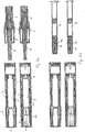
- Figures 2a to 5c comprise pairs of axial sectional views differing in perspective by 90° of rotation of the injection device around its longitudinal axis.
- FIG. 1 gives an overview of the constituents of the inventive injection device according to a preferred embodiment.
- the injection device comprises a needle protection means embodied by a front cap 1, a sleeve-shaped needle shield 2, a first casing part comprising a housing 3 and a syringe holder 9, a reservoir embodied by a syringe 11, a plunger rod 10, a second casing part comprising the plunger rod guiding means 5 and an outer casing part embodied by a proximal end cap 6, and a dosing means embodied by a dosing sleeve 7.
- the needle shield biasing means is embodied by a spiral spring 4.
- Figures 2a to 2c show the process of assembling the inventive injection device which is delivered to a user for example in the state shown in Figure 2a in which the front assembly comprising in particular the first casing part and further particularly the needle protection means 1, needle shield 2, housing 3, syringe holder 9, and spiral spring 4 is not coupled to the rear assembly comprising in particular the second casing part and further particularly the end cap 6, plunger rod guiding means 5, plunger rod 10 and dosing sleeve 7.
- the first casing part comprising the housing 3 and syringe holder 9can be engaged to the second casing part comprising the plunger rod guiding means 5 and the end cap 6 in a not proper engagement.
- the housing 3 and the end cap 6 can be detached from one another in order to insert a syringe into the housing.
- the first casing part is detached from the second casing part and a syringe 11 is inserted into the front assembly so as to be held by the syringe holder 9 as shown in Figure 2c .
- the rear assembly can then be coupled to the front assembly by pushing the distal section of the end cap 6 into the proximal section of the housing 3 when the longer casing rotation blocking rib 8b lies in the shorter rotating blocking notch 8d (more particular described below).
- the state of the injection device shown in Figure 2c is also represented in Figures 3a and 3b.
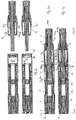
- FIGS 3a and 3b show axial sections of the inventive injection device in two planes which are perpendicular to each other.
- the needle protection means 1 comprises a flexible snap member 1a which is configured to abut a holding rib 2a of the needle shield 2, the holding rib 2a being positioned at the distal end of the needle shield 2 on its interior surface preferably around its whole circumference so as to prevent the needle protection means is from falling out of the distal end of the injection device.
- the snap member 1a can be deflected into a radially inward direction by a manual force which is applied onto the needle protection means 1 in a distal direction for pulling the needle protection means 1 off the needle shield 2.
- the snap member 1a comprises a tapered distal end surface which may slide along the holding rib 2a.
- the needle protection means 1 is not rotatable relative to the needle shield 2 in the configuration shown in Figures 3a and 3b .
- the inner boot comprises an axial rib on its outer surface which co-operates with an axial notch on an inner surface of the needle shield in order to prevent rotation of the two relative to one another.
- the needle shield 2 also comprises a proximal holding projection 2b with which it abuts the housing 3 in a distal direction and preferably engages a recess in the interior surface of the housing 3 so as to be blocked against a rotation relative to the housing 3.
- the spiral spring 4 abuts the housing 3 in a proximal direction and the needle shield 2 in a distal direction.
- the housing 3 accommodates a syringe holder 9 comprising an engagement member 9b at its proximal end which engage a holding ring 3e on the interior surface of the housing 3 so that the syringe holder 9 may not be detached from the housing 3 and in particular cannot move relative to the housing in an axial direction.
- the syringe holder 9 holds a syringe 11 comprising a syringe flange 11a and a piston 11b which is movable in the interior of the syringe 11 in an axial direction so as to exert pressure onto a medical fluid accommodated in the syringe.
- the piston 11b is moved by the plunger rod 10 if the plunger rod 10 is moved in a distal direction (for example by exerting manual pressure on an activating means embodied by the operating knob 10e disposed at the proximal end of the plunger rod 10).
- the plunger rod 10 is guided by a plunger rod guiding means 5 which is held by tensioning it between the syringe flange 11a and the end cap 6.
- the coupling means for coupling the first casing part and the second casing part to one another comprises by an engagement means comprising coupling ribs 6c, 6c' and a holding means comprising coupling notches 3g, 3g'.
- the coupling ribs 6c, 6c' and the coupling notches 3g, 3g' run in a circumferential direction.
- the end cap 6 comprises two coupling ribs 6c, 6c' on an outer surface of its distal section which are pushed into each a corresponding on of the two coupling notches 3g, 3g' on an interior surface of the housing 3 at its proximal end. Rotation of the end cap 6 relative to the housing 3 after coupling them to one another is prevented by a casing rotation blocking means comprising axial casing rotation blocking ribs 8a, 8b on an outer surface of the end cap 6 which are configured to co-operate with axial casing rotation blocking notches 8c, 8d on an interior surface of the housing 3.
- the casing rotation blocking ribs 8a, 8b have different lengths which are designed to correspond to the length of the corresponding one of the casing rotation blocking notches 8c, 8d such that the casing rotation blocking ribs 8a, 8b can be fully accommodated in the respectively corresponding rotation blocking notch 8c, 8d after coupling the end cap 6 to the housing 3.
- the longer one (8b) of the casing rotation blocking ribs lies in the shorter one (8c) of the casing rotation blocking notches, and the coupling rib 6c lying further in a distal direction lies in the coupling notch 3g' lying further in the proximal direction.
- the housing 3 and the end cap 6 are not properly coupled to each other and can be detached from one another in order to insert the syringe 11 into the housing 3.
- the first casing part and second casing part are axially and rotationally fixed to each other since the longer casing rotation blocking rib 8b lies in the longer rotation blocking notch 8d and the coupling rib 6c' of the end cup is coupled to the coupling notch 3g' of the housing 3.
- the plunger rod guiding means 5 comprises a holding means embodied by holding arms 5g which lie in recesses 6b in the interior surface of the end cap 6.
- the plunger rod guiding means 5 is tensioned by abutment of the spacing means 5a of the plunger rod guiding means 5 on the syringe flange 11a, engagement of the holding arms 5g into the recesses 6b and biasing the elastic tensioning members 5h which are disposed in a radial direction at the distal end of the plunger rod guiding means 5.
- the elastic tensioning members 5h are biased because they are pressed by the distal circumference of the outer casing part 6 into the distal direction.
- the axial blocking means which is configured to block movement of the plunger rod 10 relative to the casing 3 is embodied by elastic abutment members 5b on the plunger rod guiding means 5 which comprise abutment surfaces on their distal side which run in a substantially radial direction. Furthermore, the axial blocking means comprises blocking wings 10g which have a tapered distal surface for deflecting the elastic abutment members 5b in a radially outward direction during this movement of the plunger rod 10 in a distal direction. The blocking wings 10d furthermore comprise abutment surfaces on their proximal side which run in a substantially radial direction so as to abut the elastic abutment members 5b from the distal side after even further distal movement of the plunger rod 10.
- the plunger rod 10 is prevented from moving in the proximal direction.
- the plunger rod furthermore comprises rotational blocking surfaces 10b which are moveable on guide rails 5c of plunger rod guiding means and abut the guide rails 5c in a rotational direction.
- the guide rails 5c and the rotational blocking surfaces 10b together form the above-described rotational blocking means which prevents the plunger rod 10 from being rotated relative to the plunger rod guiding means 5 and the casing 3.
- the dosing sleeve 7 surrounds the plunger rod 10 at its proximal end and in particular also surrounds the operating knob 10e.
- the dosing sleeve 7 comprises an inner circumferential groove 7c in which a circumferential rib 10c of the plunger rod 10 lies so as to prevent movement of the dosing sleeve 7 in an axial direction relative to the plunger rod 10.
- Figures 2a , 3a , 4a and 4b show the functionality of the removing means embodied by axial hooks 1b on the proximal end of an inner boot 1c of the needle protection means 1.
- the needle protection means 1 is pulled off from the needle shield 2 in a distal direction, whereby the snap member 1a overcome the abutting resistance provided by the holding rib 2a.
- the front cap 1 can therefore be separated from the needle shield 2.
- the axial hooks 1b engage behind the proximal circumference of a discharge means cover embodied by a needle cover 12.
- the axial hooks 1b probably have a beveled proximal surface which allows to insert this syringe 11 with the needle cover 12 into the inner boot 1c in an axial direction when inserting the syringe 11 into the injection device as shown in Figures 2b and 2c .
- the axial hooks 1b can be deflected in a radially outward direction during such a movement and, when the syringe 11 and the needle cover 12 are pushed further distally, can snap behind the proximal circumference of the needle cover 12.
- the axial hooks 1b When pulling the needle protection means 1 of the needle shield 2, the axial hooks 1b then serve to take the needle cover 12 along with the needle protection means 1.
- the front cap 1 and the needle cover 12 can be removed in a single operating step. Furthermore, this feature of the front cap 1 also reduces the user's risk of injury since the user does not need to manipulate the needle cover 12 directly which might lead to accidently pricking himself on the tip of the (hollow) needle 11c which embodies the discharge means.
- Figures 5a and 5b show the configuration of the injection device after priming.
- the plunger rod 10, the piston 11b and the dosing sleeve 7 have been moved in a distal direction relative to the casing by a predetermined distance (also called priming distance) corresponding to the distance between a first axial blocking notch 10a and a second axial blocking notch 10d formed in the plunger rod 10 which are configured to accommodate the abutment members 5b disposed at diametrically opposite sides of the plunger rod guiding means 5.
- the abutment members 5b, the axial blocking notches 10a, lOd and the axial blocking wings 10g together form the axial blocking means.
- the axial abutment members 5b are configured to be moved in a radially outward direction by a force exerted by the tapered distal surfaces of the blocking wings 10g if the plunger rod is moved in a distal direction relative to the casing.
- the piston 11b is also moved by a corresponding distance into the distal direction, thereby decreasing the volume available in the syringe 11 for accommodating the medical fluid and air.
- the injection device is preferably held with its distal end pointing upward in a vertical direction so that during the priming movement of the plunger rod 10 and the piston 11b in a distal direction relative to the casing, the air will be present at the distal end of the syringe volume of the syringe 11 and will then be discharged from the syringe during the priming stroke.
- the priming stroke in particular involves the distal movement of the plunger rod 10 and the piston 11b by the aforementioned predetermined distance. By a predetermined distance which is suitable to de-air the syringe 11.
- FIG. 5b shows that, compared to the configuration shown in for example Figure 4b , the dosing sleeve 7 was moved in the distal direction by the priming distance.
- the plunger rod guiding means 5 remains at a fixed position relative to the casing (in particular relative to the housing 3 and the end cap 6) during the priming stroke.
- the dosing sleeve 7 then moves in a distal direction by the priming distance relative to the plunger rod guiding means 5 during the priming stroke.
- the deflecting means 7d of the dosing control means then lies over the rotational limitation means 5e. In particular, the deflecting means 7d abuts the rotation limitation means 5e in a radially inward direction and deflects the rotation limitation means 5e in the radially inward direction.
- the deflecting means 7d takes the form of a projection on an inner surface of the dosing sleeve 7, and the rotation limitation means 5e is embodied by a flexible tongue having a tapered proximal surface so that the deflecting means 7d can be pushed in a distal direction onto the rotation limitation means 5e at least at the end of the priming stroke.
- the dosing sleeve 7, the plunger rod 10, the position of the blocking wings 10g and the axial blocking notches 10a, 10d on the plunger rod 10 and the rotation limitation means 5e on the plunger rod guiding means 5 are dimensioned such that the distance which the plunger rod 10 travels during the priming stroke corresponds to the distance which the deflecting means 7d has to travel in order to move from its position shown in Figure 4b to its position shown in Figure 5b , in particular in order to deflect the rotation limitation means 5e.
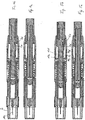
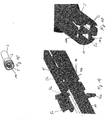
- Figure 5c shows a sequence of operation of the injection device in pairs of sectional views representing perspectives from directions perpendicular to one another.
- Sub- figures (1 ) and (1') show the state of the injection device after the first casing part and the second casing part have been coupled to one another and after the injection device has been primed.
- the needle 11c is extending distally out from the needle shield 2 because the injection device has been pressed onto the injection location such that the needle is inserted into the injection location and the needle shield 2 is pushed proximally into its retracted position inside the housing.
- the subsequent operational step is illustrated by sub- figures (2 ) and (2'). In these Figures, the needle shield still is in its retracted position and the piston 11b is in its most a distal position, i.e.
- Sub-figures (3) to (4') show the state of the injection device after lifting it off from the injection location so that the needle shield 2 extends into its forward position in order to surround the needle 11c. In this state, the needle shield 2 is - as explained further below - prevented from being pushed in the proximal direction again.
- the elastic members 5h are, as also shown in Figure 16 , formed as part of the plunger rod guiding means 5 and are disposed on a circumferential ring substantially at the distal end of the plunger rod guiding means 5 and proximal of the axial protrusion 5e which constitute the spacing means for spacing the plunger rod guiding means from the syringe flange 11a.
- the holding arms 5g lie in the recesses 6b of the end cap 6.
- engagement members formed at the ends of the holding arms 5g abut the distal limitation of the recesses 6b.
- Figures 8 and 9 show the features also shown in Figures 6 and 7 in the configuration in which the reassembly has been coupled to the front assembly.
- the holding arms 5g now abut the proximal limitations of the recesses 6b in the end cap 6.
- the tensioning means 5h are deformed and biased.
- the bases of the elastic members of the tensioning means 5h are pushed in a proximal direction compared to the configuration shown in Figures 6 and 7 , while their outer radial ends abut the distal circumference of the end cap 6 and substantially remain in the position which they had in the configuration shown in Figures 6 and 7 .
- the plunger rod guiding means 5 is tensioned relative to the casing, in particular relative to the end cap 6, and by the abutment between the holding arms 5g and the recesses 6b remains in an axially fixed position relative to the end cap 6.
- Figures 10a and Figures 10b show a further detail of how the axial blocking means functions.
- the abutment member lies in the first axial blocking notch 10a and distally of a first blocking wing 10g (compare Figure 10a).
- Figure 10b shows the configuration after priming, in which the abutment member 5b lies in the second axial blocking notch 10b at a position which is proximal relative to the first blocking wing 10g and distal relative to a second axial blocking wing 10g'.
- Figure 11a shows the position of the deflecting means 7d relative to the rotation limitation means 5e before priming.
- the deflecting means 7d lies radially further outward relative to the rotation limitation means 5e and at a position proximal of the rotation limitation means 5e.
- Figure 11b shows the situation at the end of the priming stroke, when the deflecting means 7d lies radially further outward than the rotation limitation means 5e and at substantially the same axial position as the rotation limitation means 5e. In this situation, the deflecting means 7d depresses the rotation limitation means 5e in a radially inward direction. Furthermore, the deflecting means 7d abuts the distal projection 5d of the dose blocking means in a distal direction.
- Figure 12a shows a further perspective of the plunger rod guiding means 5, the rotation limitation means 5e and the distal projection 5d of the dose blocking means.
- Figure 12b shows a perspective axial section of the dosing sleeve 7.
- a dose to be injected is defined by rotating the dosing sleeve 7 relative to the casing, in particular relative to the plunger rod guiding means so that the rotation limitation means is axially aligned with a dose defining groove 7e, 7e'.
- the plunger rod 10 and the dosing sleeve 7 can then be moved in the distal direction so that the projection formed on the distal end of the rotation limitation means 5e can move in an axial direction relative to the dosing sleeve 7 within the selected dose defining groove 7e, 7e'.
- the plunger rod is therefore able to move by a distance which corresponds to the distance between the distal end surface of the deflecting means 7d and the proximal end of the respective dose defining groove 7e, 7e'.
- the length of the selected dose defining groove 7e, 7e' governs the amount of medical fluid which can be discharged, i.e. the dose to be injected.
- the plunger rod 10 can be moved in the distal direction relative to the casing until the projection 7f, 7f located at the proximal end of the selected dose defining groove 7e, 7e' abuts the distal projection 5d of the dose blocking means.
- the inventive injection device therefore preferably constitutes a single-use injection device.
- the dosing sleeve 7 has on its interior surface axial dose defining grooves 7e, 7e' which at their proximal ends comprise circumferential projections and 7f, 7f which belong to the dose locking means. Furthermore, the dosing sleeve 7 comprises the deflecting means 7d, the axial surfaces 7d' of which co-operate with the axial surfaces 5e' of the rotation limitation means 5e in order to function as part of the dosing control means which prevents a rotation of the dosing sleeve back into the position which the dosing sleeve had (for example the position shown in Figure 11b ) in particular relative to the casing (more particularly, relative to the plunger rod guiding means 5) at the end of the priming stroke.
- the dosing sleeve 7 comprises on its interior surface a projection 7b which together with an axial notch 6c on an interior surface of the end cap 6 as shown in Figures 13 and 14 co-operates to function as a means for preventing rotation of the dosing sleeve 7 relative to the casing before (in particular until) a priming operation (i.e. a priming stroke) for priming the reservoir (in particular the syringe 11) is completed.
- the axial notch 6c is open in at least one axial direction, in particular in the distal axial direction (i.e. at its distal end).
- the projection 7b of the rotation prevention means has to travel a distance corresponding to the priming stroke in order to exit the axial groove 6c in a distal direction, whereby a rotation of the dosing sleeve 7 relative to the end cap 6 and the plunger rod guiding means 5 is allowed.
- Figure 13 shows the position of the projection 7b in the axial groove 6c before the priming stroke
- Figure 14 shows the position of the projection 7b at the end of the priming stroke 6c, i.e. after the priming stroke has been completed.
- the dosing sleeve 7 also comprises a part of a ratchet means.
- the ratchet means comprises projections 7g which run substantially parallel to the axial direction and recesses 7h between the projections 7g which also run substantially parallel to the axial direction. Projections 7g and recesses 7h are provided at the proximal end of the dosing sleeve 7 on its interior surface which lies opposite an exterior surface of the plunger rod 10, in particular of the operating knob 10e.
- the plunger rod 10 comprises ratchet springs 10i which are able to elastically move in a radial direction and during the rotation of the dosing sleeve 7 for aligning a dose defining groove 7e, 7e' with the dose blocking means 5e, 5d co-operate with the projections 7g and the recessed 7h to function as a ratchet means.
- the ratchet springs 10i move over the projections 7h, whereby the ratchet springs 10i are mechanically excited so as to emit a tactile and acoustic vibration which indicates the dosing operation to the user.
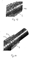
- Figure 15 shows the general structure of the dosing sleeve 7, the end cap 6, the plunger rod 10 and the plunger rod guiding means 5. Details of how the plunger rod 10 is guided in the plunger rod guiding means 5 are also shown in Figure 17 .
- the plunger rod 10 comprises a rotational blocking means embodied by rotational blocking surfaces 10b which substantially run in an axial direction and are in form-fit with guide rails 5c on the interior surface of the plunger rod guiding means 5.
- the rotational blocking surfaces 10b and the guide rails 5c support stable axial movement of the plunger rod 10 and prevent the plunger rod 10 from being rotated relative to the casing (in particular relative to the plunger rod guiding means 5) in particular in the configuration in which the front assembly has been coupled to the rear assembly.
- the rotational blocking surfaces 10b and the guide rails 5c therefore serve as a rotational blocking means which is configured to block a rotation of the plunger rod 10 relative to the casing.
- the plunger rod guiding means 5 is held in the end cap 6 and is at least partly surrounded by the dosing sleeve 7.
- the plunger rod 10 is at least partly accommodated by the plunger rod guiding means 5, as shown in Figure 15 .
- the above-mentioned rotational blocking means embodied by the rotational blocking surfaces 10b may also serve as an axial stabilizing means.
- the axial stabilizing means is in particular configured to stabilize the plunger rod while coupling the first casing part to the second casing part and while moving the plunger rod in a distal direction during priming and fluid discharge.
- Figures 19a to 19c explain the functionality of the needle shield blocking means.
- Figure 19a shows the configuration of the needle shield blocking means in an initial state of the injection device which is in particular a delivery state.
- the syringe holder 9 comprises a second axial locking member embodied by an elastic latch 9c on an interior surface of the syringe holder 9, the elastic latch 9c extending in the proximal direction.
- the latch 9c is fastened with its base at the distal end of the latch 9c to the interior surface of the syringe holder 9 and comprises at its proximal end a hook having a tapered surface pointing in the proximal direction.
- the needle shield 2 comprises a first axial locking member embodied by an elastic latch 2d extending in the distal direction which is configured to lie at the substantially same axial position as the latch 9c and is fastened with its base at the proximal end of the latch 2d to the needle shield 2.
- the latch 2d At its distal end, the latch 2d comprises a counter-hook which is generally configured to engage with the hook on the latch 9c.
- the needle shield blocking means in constituted in particular by the hook latches 2d, 9c.
- Figure 19a shows an initial state of the needle shield blocking means which is for example a delivery state. In that state, the latch 2d on the needle shield 2 is configured to lie on the latch 9c of the syringe holders so that the hook and the counter-hook are not engaged.
- the needle shield 2 When the injection device is pressed onto the injection location, the needle shield 2 is moved in a proximal direction relative to the casing and relative to the syringe holder 9. This leads to the latch 2d being moved away from the latch 9c such that the two latches essentially lie opposite each other in an axial direction. In particular, the two latches do not overlap anymore. This state is shown in Figure 19b .
- the needle shield 2 is pushed in the distal direction relative to the casing by the spiral spring 4 such that the latch 2d on the needle shield 2 is pushed under the latch 9c on the syringe holder 9 such that the hook and the counter-hook, respectively, on the two latches 2d, 9c engage with each other.
- at least one of the two latches has a tapered surface.
- the latch 9c has a tapered surface along which the counter-hook on the latch 2d is able to move in order to engage with the hook on the latch 9c.
- the latch 2d Due to the engagement of the hook and the counter-hook, the latch 2d is limited in its distal movement by the base of the latch 9c which in the end leads to blocking the axial movement of the needle shield 2 relative to the syringe holder 9 and relative to the casing. In particular, the latch 2d is rested by the latch 9c in those axial directions.
- Figures 20a and 20b show two perspectives of a front cap 1 having a buffer means 14 at its distal end.
- the buffer means 14 is embodied by a circular ring which is fastened to the front cap 1 with connector elements (buffer connectors) 15 embodied by buffer connectors which run in an oblique direction relative to the axial and the circumferential direction of the front cap 1 or the injection device, respectively.
- Figures 21a to 21e show further embodiments of a front cap 1 having a buffer means 14. These embodiments also each comprise a gripping means 16 embodied by two rounded projections located at diametrically opposite positions on the proximal end circumference (i.e. the proximal rim) of the front cap 1.
- the buffer means 14 takes the form of four projections which are bent in a radially outward direction and are provided spaced by 90° at positions on the distal end circumference (i.e. the distal rim) of the front cap 1.
- the buffer means 14 is embodied by an elastic hoop running parallel to a diameter of the distal front surface of the front cap 1 and connected to the distal front surface with a connector element (buffer connector) 15 at each end of the hoop.
- the buffer means 14 is embodied by two rounded axial projections which project out of the distal front surface of the front cap 1 - in this case no connector elements are required to connect the buffer means 14 to the remainder of the front cap 1.
- the buffer means 14 is embodied by a circular ring provided on a central connector element 15.
- the circular ring carries rounded axial projections.
- the buffer means 14 is embodied by a buckled circular ring which is connected to the front cap 1 with buffer connectors 15 located on the axis around which the circular ring is buckled.
- the buffer means 14 looks like a hyperbola.
- Figure 21f contains further views of the buffer means 1 shown in Figures 20a and 20b combined in a front cap 1 with a gripping means 16.
Landscapes
- Health & Medical Sciences (AREA)
- Engineering & Computer Science (AREA)
- Hematology (AREA)
- Anesthesiology (AREA)
- Biomedical Technology (AREA)
- Heart & Thoracic Surgery (AREA)
- Vascular Medicine (AREA)
- Life Sciences & Earth Sciences (AREA)
- Animal Behavior & Ethology (AREA)
- General Health & Medical Sciences (AREA)
- Public Health (AREA)
- Veterinary Medicine (AREA)
- Environmental & Geological Engineering (AREA)
- Infusion, Injection, And Reservoir Apparatuses (AREA)
Description
- The invention (which is also called "Injection device with dosing control means") is directed to an injection device according to the independent apparatus claim.
- When using an injection device for injecting a medical fluid such as a liquid drug into a patient's body, the injection device has to be primed, i.e. the reservoir in which the liquid drug is stored has to be de-aired. Otherwise, a risk of injecting air into the patient's blood vessels may arise which might lead to an embolism. Many injection devices therefore incorporate a means for priming the injection device. Such a priming means in general requires the injection device to be primed before a dose of the fluid to be injected can be selected. A known problem in such injection devices is that a user may erroneously move the priming means back into a position which it had before priming or at the end of the priming operation which may lead to undesired accumulation of air in the reservoir.
-
WO2012/118687A1 discloses a manually operated injector which comprises a plunger sleeve 40 having a key guide 41. The key guide 41 prevents distal movement of the plunger sleeve 40 after priming and prior to dose setting. -
WO2007/066152A2 discloses a delivery device which comprises a priming button 200 having ring 245 disposed on its surface. Ring 245 is opened by a gateway 240 in order to allow to pass a priming button locking rib 270 during priming. The priming button 200 cannot be moved in proximal direction once priming operation has been performed. - A problem to be solved by the present invention therefore is to provide an alternative injection device which on the one hand requires a user to first prime the injection device before selecting a dose to be injected and on the other hand avoids undesired accumulation of air in the reservoir after a priming operation has been completed.
- This problem is solved by the subject matter of the independent claim, wherein the dependent claims relate to preferred embodiments of the present invention.
- The inventive injection device preferably comprises a casing which accommodates or forms a reservoir for a drug, in particular a fluid drug such as a liquid drug. The casing preferably comprises an outer structure of the injection device, i.e. a structure which comprises an outer surface of the injection device. In particular, the casing also serves as a holding means for the injection device with which a user holds the injection device for operating it. The injection device is in particular any one of a manually operated syringe and an injection device comprising a mechanism for automatic execution of an injection and discharge sequence (in particular represented by an autoinjector). For example, the casing comprises a sleeve which surrounds the reservoir. Preferably, the sleeve is cylindrical and hollow in its interior in order to accommodate the reservoir. Preferably the casing comprises, in particular accommodates a reservoir holder (e.g. a syringe holder) for holding the reservoir. According to a preferred embodiment, the casing comprises a first casing part and a second casing part (which is in particular different from the first casing part, i.e. is not comprised in the first casing part). The second casing part can preferably be coupled to the first casing part in particular such that the first casing part and the second casing part cannot move relative to each other in an axial direction of the injection device.
- The axial direction of the injection device in particular is a direction which extends in particular in the direction of a longitudinal axis of the injection device (e.g. a cylinder axis if the injection device possesses a substantially cylindrical shape). A distal and/or forward direction of the injection device is parallel to the axial direction and points in particular in the direction in which the medical fluid is to be expelled (therefore, it points towards a forward and/or front and/or distal end of the injection device at which a discharge means for discharging a fluid such as a needle is disposed. A proximal and/or backward direction of the injection device also runs parallel to the axial direction and points in particular towards a backward and/or rear and/or proximal end of the injection device which lies opposite the distal end at which in particular an activation means such as an operation knob which is coupled to a plunger rod for applying a discharging force is disposed. During injection, the distal end of the injection device points in particular towards a location of the patient's body at which the injection is to be performed (i.e. an injection location).
- The first casing part preferably is a part of the casing which lies further to the distal end than the second casing part which preferably lies further towards the proximal end. In a delivery state in which the injection device is delivered to the user, the first casing part and the second casing part are preferably not coupled to each other. For coupling the first and the second casing part to each other, the second casing part is for example screwed to the first casing part, each casing part therefore preferably has a corresponding screw thread. For example, both the first casing part and the second casing part have the basic geometry of a hollow cylinder, the first casing part comprises an internal thread on its interior surface at its proximal end, and the second casing part comprises a screw thread on its external surface at its distal end. The second casing part can then be screwed into the first casing part. Preferably, the first casing part and the second casing part are then coupled to each other such that they cannot move relative to each other in an axial direction. Further preferably, they are also coupled to each other such that they cannot rotate relative to each other. For example, at least one of the first and second casing parts may be provided with a coupling means embodied by e.g. an engagement means which engages a groove on the other one of the first and second casing parts at the end of the screwing operation and which prevents unscrewing the first and second casing parts from one another. According to another embodiment of the first aspect of the invention, the first and second casing parts may be coupled to each other with a coupling means embodied for example by a snap-fit between for example an engagement means such as a flexible hook provided on at least one of the first and second casing parts and a corresponding holding means into which the hook is snapped when coupling the first and second casing parts.
- According to a particularly preferred embodiment of the invention, the coupling means comprises an engagement means which takes the form of at least one circumferential rib (preferably, two circumferential ribs) on an outer surface of the second casing part which is inserted into the proximal end of the first casing part. The first casing part preferably comprises a holding means embodied by at least one circumferential notch (the number of notches being preferably equal to the number of ribs on the second casing part) in which the circumferential ribs on the second casing part are configured to lie after coupling the first casing part and the second casing part. In order to prevent a rotation of the first casing part relative to the second casing part after coupling them to each other, the injection device preferably comprises a casing rotation blocking means, which includes for example at least one axial rib on an outer surface of the second casing part which is inserted into the first casing part, and the first casing part comprises at least one axial notch (the number of notches being preferably equal to the number of axial ribs on the second casing part) in which the axial rib of the second casing part is configured to lie after coupling the first casing part to the second casing part. The coupling means comprises at least the engagement means and the holding means, preferably the holding means also comprises the casing rotation blocking means. In the case of more than one axial rib on the second casing part, the axial ribs are preferably of different axial length, and the corresponding axial notches on the first casing part are preferably of different axial length, the axial notches of different lengths each being designed to accommodate one of the axial ribs having a corresponding axial length. Furthermore, the pairs of corresponding axial ribs and axial notches are positioned in the axial direction such that, if the first casing part and the second casing part are positioned in a rotational position (in the sense of a rotation along their longitudinal axes) such that an axial ribs lies in an axial notch of short length than the axial rib, the second casing part cannot be coupled to (in particular not fully inserted into) the first casing part. Such a configuration corresponds to a delivery state of the injection vice in which it is delivered to a user. In that configuration, preferably only one of a possible plurality of the circumferential ribs on the second casing part lies in one of the possible plurality of circumferential notches in the first casing part. In particular, the more distal circumferential ribs lies in the more proximal circumferential notch. In that configuration the second casing part and the first casing part remain detachable from one another. This configuration may therefore also be denoted as a partly coupled configuration of the coupling means.
- The reservoir may be an integral feature of the casing or be present in the form of the reservoir of a syringe which is filled with a medical fluid to be injected. In particular, the reservoir is not formed integrally with the casing and may be inserted into the casing, in particular into the first casing part, before coupling the first casing part and the second casing part. During operation of the injection device, in particular when the reservoir is accommodated by the casing, further particularly during injection, the reservoir preferably rests relative to the casing, in particular relative to the first casing part.
- The injection device furthermore preferably comprises a plunger rod which can move relative to the casing in an axially forward direction to deliver the drug. The plunger rod in particular is configured to move a piston in the reservoir in particular in the distal direction in order to increase the pressure on the drug such that it is discharged from the reservoir. The plunger rod is preferably connected to an activating means such as an operating knob at its proximal end on which the user can exert for example manual pressure in order to move the plunger rod into the distal direction. The activating means and the plunger rod may be formed integrally, i.e. as one part, or as separate parts which have a preferably fixed position (in particular in an axial direction, preferably also in a rotational direction) relative to each other.
- The injection device preferably also comprises a dosing means which can move in the forward direction relative to the casing relative to the casing in order to prime the reservoir, i.e. to de-air it. The dosing means is preferably provided on the casing, in particular the second casing part, and for example takes the form of a cylindrical hollow sleeve which is movable relative to the second casing part. For example, the dosing means is accommodated by the second casing part, in particular an outer casing part of the second casing part such as a proximal end cap of the casing which is part of the second casing part. Preferably, the dosing means can rotate relative to the casing, in particular relative to the second casing part, for selecting a dose to be injected. Furthermore, the dosing means accommodates at least part of the plunger rod and in particular also the activating means and preferably can also rotate relative to the plunger rod and/or the activating means. For example, the dosing means is provided with an internal circumferential groove in which a corresponding circumferential projection of the plunger rod and/or activating means (in particular a sum piece) is located such that an axial movement of the dosing means relative to the plunger rod and/or the activating means is prohibited.
- Preferably, rotation of the dosing means relative to the casing is prevented in particular before (more particularly, until) a priming operation for priming the reservoir is completed. In particular, such a rotation of the dosing means is prevented after coupling the first casing part to the second casing part. The dosing means preferably comprises a dosing control means which is configured to prevent or enable rotation of the dosing means. The dosing control means comprises an engagement means (for example a protrusion provided on an exterior surface of the dosing means) and engages with a rotation prevention means embodied by e.g. a groove on the interior surface of the second casing part. The protrusion is configured to lie in the groove in particular after coupling the first casing part and the second casing part to each other. The engagement means is configured to engage the rotation prevention means in particular before (more particularly until) the priming stroke is completed. The groove preferably is open at least in a distal direction such that, upon moving the dosing means in the forward direction relative to the casing, the protrusion exits the groove in order to enable rotation of the dosing means relative to the casing, in particular relative to the second casing part. The groove is preferably dimensioned in particular in its axial direction such that the distance which the protrusion of the dosing means has to travel in order to enable its rotation (i.e. to exit the groove) is equivalent to (in particular equal) the distance which the plunger rod has to travel during a priming stroke. The dosing control means furthermore preferably comprises a deflecting means (e.g. a protrusion on its interior surface in particular at its distal end) which, in particular after coupling the first casing part and the second casing part to each other, is aligned with a rotation limitation means disposed on the casing, in particular the second casing part, and which, during forward movement of the dosing means for priming clears the rotation prevention means, in particular deflects it (preferably in a radially inward direction). The deflecting means is configured to deflect the rotation limitation means in particular at the end of the priming stroke. The rotation limitation means is configured such that it prohibits complete rotation (in particular around the whole circumference of the injection device by in particular 360°) of the dosing means relative to the casing in particular after the dosing means has been rotated out of the position which it attains at the end of the priming stroke. It is also configured such that the dosing means is allowed to rotate only partially (i.e. less than a complete rotation, i.e. less than 360°) relative to the casing in particular after the dosing means has been rotated out of the position which the dosing means attains at the end of the priming stroke. Such a rotation which is allowed for only less than 360° around the axial direction is also called a limited rotation.
- For example, the second casing part comprises the aforementioned outer casing part and a plunger rod guiding means which may be formed integrally with each other or as separate structures. Preferably, the plunger rod guiding means is disposed in the interior of the outer casing part and the rotation limitation means is located on the plunger rod guiding means. For example, the plunger rod guiding means has the basic shape of a hollow cylinder, in the interior of which the plunger rod is guided, and is provided with the rotation limitation means which may be embodied for example by a spring disposed in an exterior surface of the plunger rod guiding means. Preferably, the plunger rod guiding means is disposed such that it is at least partially surrounded by the dosing means. In summary, the plunger rod guiding means is preferably at least partly surrounded by the dosing means, and the dosing means is preferably at least partly surrounded by the outer casing part.
- The deflecting means preferably has a circumferential extent on the interior surface of the dosing means which covers only part, i.e. not all, of the interior circumference of the dosing means. In particular, at least a part of the interior circumference corresponding to the circumferential extent of the rotation prevention means is not covered by the deflecting means. This means, when the dosing means is rotated in a circumferential direction, the deflecting means is moved circumferentially away from the rotation prevention means which then (due to its elasticity) moves back into its position which it had before initiating the priming stroke, in particular it moves in a radially outward direction. The deflecting means comprises in particular a slanted surface at its distal end such that it can be pushed over the rotation limitation means in order to deflect the rotation limitation means in particular in a radially inward direction of the injection device. The rotation limitation means preferably is elastic such that, after moving the deflecting means in a circumferential direction away from the rotation limitation means, the rotation limitation means moves back into its position which it had before initiating the priming stroke, in particular before being deflected by the deflecting means. Since both the rotation limitation means and the deflecting means preferably have a reversal prevention means which prevents a reverse movement of the dosing means into the position which it had at the end of the priming stroke (such as side surfaces on both the deflecting means and the rotation limitation means parallel to an axial direction which run in a substantially radial direction), it will not be possible to rotate the dosing means back into the position relative to the casing which it had at the end of the priming stroke. In such a case, the axial side surface of the deflecting means would abut the axial side surface of the rotation limitation means without being able to be moved over the rotation limitation means, i.e. without being able to deflect the rotation limitation means again. The dosing control means therefore is preferably configured to prevent a rotation of the dosing means back into the position which the dosing means had at the end of the priming stroke relative to the casing. The dosing means is rotated in particular in order to select a dose of the medical fluid to be injected, the dosing control means is therefore further configured to abut the rotation limitation means as soon as the dosing means has been rotated for selecting the dose, in particular after selecting the dose.
- Preferably, the dosing means comprises a dose defining means which is configured to define the dose to be injected. The dose defining means comprises for example at least one dose defining groove (in particular a plurality of grooves) disposed on the interior surface of the dosing means and running in an axial direction. The length of each dose defining groove defines the dose to be injected. The dose defining means preferably comprises a dose locking means which is constituted to lock the dosing means at the end of a discharge operation for discharging the medical fluid (in particular at the end of a discharge stroke). For example the dosing means a dose locking means which is configured to lock the dosing means in particular after discharging the medical fluid from the reservoir in particular such that the dosing means cannot move relative to the casing. For example, a dose locking means comprising a protrusion disposed at the proximal end of each dose defining groove. The dose locking means preferably comprises a dose blocking means which is disposed in particular on the casing, more particularly on the second casing part such as on the plunger rod guiding means. For example, the dose blocking means comprises an elastic member which can be depressed by the dose locking means when the plunger rod and therefore also the dosing means are moved in a distal direction and in particular at the end of the discharge operation. In particular, the protrusion of the dose locking means engage the dose blocking means in particular by snapping over the elastic member of the dose blocking means at the end of the discharge operation in such a manner that moving the dosing means in the proximal direction after completing the discharge operation is prevented. In particular, the protrusion of the dose locking means has a surface at its proximal side which runs in a substantially radial direction and the dose blocking means has a surface at its distal side which also runs in a substantially radial direction such that, if a user tries to move the dosing means in a proximal direction after completing the discharge operation, the dose blocking means and the protrusion abut each other, thereby preventing the proximal movement of the dosing means. Additionally, the dose blocking means preferably comprises a protrusion which, at completion of the discharge operation, lies distally of and abuts the protrusion of the dose locking means. This protrusion serves to limit a forward movement of the dosing means and therefore also the plunger rod to the distance necessary to discharge the selected volume (dose) of the medical fluid. According to a very preferred embodiment of the first aspect of the invention, the rotation limitation means is at least partly identical to the dose blocking means. For example, the elastic member of the dose blocking means also serves as the rotation limitation means.
- Preferably, the injection device comprises a plunger rod guiding means which is in particular part of the second casing part. The plunger rod guiding means preferably has the basic shape of a hollow cylinder, in the interior and in the axial direction of which the plunger rod is able to move in particular in the distal direction in order to effect discharge of the medical fluid. The plunger rod guiding means preferably comprises at least one guide rail which engages a respective at least one axial protrusion on the plunger rod such that the plunger rod cannot rotate relative to the plunger rod guiding means. Preferably, the plunger rod guiding means comprises two such guide rails which each comprises two axial protrusions on an inner surface of the plunger rod guiding means which lie opposite both sides of the axial protrusion of the plunger rod. The axial protrusion of the plunger rod is able to move in an axial direction in the guide rail by which it is surrounded. Furthermore, the plunger rod guiding means preferably comprises at least one elastic member which is able to move in a radial direction of the injection device, i.e. in a direction perpendicular to the axial direction. The elastic member preferably serves as a rotational blocking means which is configured to block an axial movement of the plunger rod relative to the casing in particular in a proximal direction. The axial blocking means is configured to co-operate with at least one radial protrusion on the plunger rod which, during distal movement of the plunger rod, deflects the axial blocking means in a radially outward direction so as to enable movement of the plunger rod relative to the axial blocking means. If the plunger rod is then moved further in a distal direction, the axial blocking means preferably moves back into its previous position which it had before being deflected by the radial protrusion of the plunger rod. The axial blocking means and the radial protrusion on the plunger rod then lie opposite each other and in particular have respectively configured surfaces which prohibit a proximal movement of the plunger rod for example by an abutment between the axial blocking means and the radial protrusion. Preferably, the plunger rod has at least one, in particular a plurality, of such radial protrusions on one of its sides and a corresponding number of radial protrusions on a diametrically opposite side at diametrically opposite positions.
- The plunger rod guiding means is preferably disposed in an outer casing part which is in particular part of the second casing part and is embodied in particular by an end cap. The plunger rod guiding means preferably comprises holding means for holding the plunger rod guiding means in the outer casing part in particular such that the plunger rod guiding means and the outer casing part are moveable relative to each other for example in an axial direction (in particular before completing coupling of the first casing part to the second casing part). It is preferred that the plunger rod guiding means and the outer casing part are moveable relative to each other before coupling the first casing part to the second casing part. For example, the plunger rod guiding means comprises hooks which are disposed on radial projections at diametrically opposite oppositions on an outer surface of the plunger rod guiding means. The outer casing part preferably comprises at least one recess (the number of recesses corresponding to the number of hooks on the plunger rod guiding means) in which the hooks may lie. The recesses are preferably dimensioned such that the hooks are able to move within the recesses in particular before completing coupling of the first casing part to the second casing part. The hooks are preferably configured to abut a distal limitation of the recess in order to prevent the plunger rod guiding means from being extracted out of the outer casing part.
- Furthermore, the second casing part (in particular the plunger rod guiding means) comprises a tensioning means for tensioning the plunger rod guiding means relative to the outer casing part. The effect of such tensioning is in particular that the plunger rod guiding means is at least substantially not moveable relative to the outer casing part in an axial direction in particular after coupling the first casing part to the second casing part. The tensioning means is preferably embodied by an elastic member, for example at least one radial protrusion (further preferably two radial protrusions at diametrically opposite positions) on an outer surface of the plunger rod guiding means at advantageously its distal end. In particular the elastic member, when coupling the second casing part to the first casing part, abuts the distal circumference of the outer casing part with its radially outer end and is pressed, at its base (i.e. at the radially inner end of a protrusion forming the elastic member) in a proximal direction by a force exerted on it by the first casing part or the reservoir (for example the proximal flange of the syringe) in a proximal direction. The elasticity of the tensioning means is preferably designed such that for example syringe flanges of differing thickness may be accommodated by the inventive injection device while ensuring in co-operation with the dimensioning of the recess (or recesses, respectively) in the outer casing part and the size of the holding means of the plunger rod guiding means that the plunger rod guiding means is stably held in a fixed (in particular axial and preferably also rotational) position relative to the casing after assembling the injection device (i.e. after coupling the second casing part to the first casing part comprising the reservoir). In accordance with the aforementioned description, this is achieved by a form-force fit between the first casing part or the reservoir, the outer casing part and the plunger rod guiding means.
- Preferably, the tensioning means comprises a spacing means which is configured to space the second casing part from the reservoir (for example a syringe) in particular after - if necessary - inserting the reservoir into the first casing part and more particularly after coupling the first casing part to the second casing part. The spacing means is preferably embodied by an axial protrusion on the distal end of the plunger rod guiding means. Preferably, a plurality of such protrusions is disposed in the circumferential direction of the plunger rod guiding means at its distal end.
- In summary, the movability of the plunger rod guiding means relative to the outer casing part before assembling the injection device and the aforementioned form-force fit allow to provide a multi-part injection device which may accommodate syringes of different sizes in particular while allowing easy assembly of the injection device into a mechanically stable structure.
- Preferably, the dosing means comprises a ratchet means comprising recesses and protrusions which are configured to co-operate with recesses and protrusions having a fixed position relative to the plunger rod. In particular, the ratchet means comprises recesses and protrusions which are preferably disposed on the plunger rod. During rotation of the dosing means relative to the plunger rod (for example when selecting a dose to be injected), the recesses and protrusions which are alternately disposed along an inner circumference of the dosing means (for example at its proximal end) move over the recesses and protrusions on the plunger rod (which are for example disposed on the outer circumference of the activation means which is surrounded by the dosing means). The ratchet means is preferably configured such that it may be activated by manual force. Since the plunger rod preferably cannot rotate relative to the casing, the ratchet means is preferably activated by rotating the dosing means relative to the casing. This serves in particular to give the user a tactile and acoustic feedback during a dose selecting operation.
- The injection device furthermore preferably comprises a needle shield which is in particular moveable in an axial direction and a needle shield biasing means configured to bias the needle shield in an axially forward direction. The needle shield is preferably embodied by a sleeve having the basic shape of for example a hollow cylinder which is disposed inside or around the casing (in particular the first casing part) substantially at its distal end. Before pressing the injection device onto an injection location at which the injection of the medical fluid is to be effected, the needle shield is in its forward position in which it preferably extends outside the casing over its distal end and surrounds a discharge means such as a needle comprised in the injection device. The needle shield is held in this position by the needle shield biasing means which is embodied by for example a spiral spring which abuts in particular at its proximal end the casing and at its distal end the needle shield. In the aforementioned forward position of the needle shield, the needle shield biasing means is in its relaxed state. When pressing the injection device onto the injection location, the needle shield is pressed against the biasing means which is then compressed (and therefore biased) and allows the needle shield to move in a proximal direction relative to the casing (i.e. into its backward position). In the backward position of the needle shield, a discharge means such as a needle connected to the reservoir is exposed. In its forward position, the needle shield surrounds the discharge means preferably along at least substantially the complete axial length of discharge means. In its backward position, the needle shield allows the discharge means to be at least partially exposed in order to for example pierce the skin of a patient.
- The injection device furthermore preferably comprises a needle shield locking means which is configured to lock the needle shield in an axially fixed position in order to prohibit axial movement of the needle shield in particular in a proximal direction relative to the casing after performing an injection. In particular, such movement of the needle shield is prohibited after the needle shield has been moved into its backward position and the needle shield biasing means is at least partly relaxed. The needle shield locking means is embodied for example by a first axial locking member such as an elastic member such as a hook disposed on the needle shield and a second axial locking member such as an elastic member such as a counter-hook disposed on the casing (in particular on the first casing part and/or on a constituent of the first casing part such as a syringe holder). The hook of the first axial locking member is preferably configured to engage with, in particular snap over, the counter-hook disposed on the casing during backward movement of the needle shield. Once the user removes the injection device again from the injection location after performing an injection, the needle shield biasing means moves the needle shield back towards its forward position such that the hook and the counter-hook abut each other. Preferably, the counter-hook abuts the base of the hook disposed on the needle shield so that a repeated proximal movement of the needle shield is prohibited.
- The injection device preferably comprises a needle protection means such as a protective cap (e.g. a needle cap, also called front cap) disposed at its distal end. The needle protection means preferably has the basic shape of a hollow cylinder which can be fitted preferably over or into the needle shield and further preferably, at its proximal end, abuts the distal circumference of the casing. The needle protection means is preferably provided with a removing means for removing a needle cover. The removing means is embodied in particular by an inner boot disposed in the interior of the needle protection means and for example has the basic shape of a hollow cylinder having a plurality of axial hooks (e.g. two such hooks) extending at its proximal end in an axial direction which are configured to engage behind a removable discharge means cover (e.g. a needle cover) disposed on the distal end of the reservoir (in particular a syringe). The discharge means cover serves to cover the discharge means (in particular the needle). The inner boot is configured to accommodate the needle cover. For example, a pre-filled syringe may be supplied which has to be fitted into the first casing part by the user, whereafter the injection device is assembled by coupling the first casing part to the second casing part. When fitting the syringe into the first casing part, the syringe is pushed in a distal direction into the casing, at the distal end of which the needle protection means is disposed. The distal end of the syringe is then pushed into the removing means, whereby the axial hook snap behind the proximal circumference of the needle cover. Once the user wishes to use the injection device, he removes the needle protection means (i.e. the end cap), and the axial hooks then take with them the needle cover and therefore serve as a removing means for removing the needle cover from the distal end of the syringe such that the needle is exposed to the atmosphere and may be used. In particular, the discharge means cover is removed simultaneously with removing the needle protection means from the injection device.
- The needle protection means is preferably provided with a buffer means for buffering (in particular absorbing and/or damping) a mechanical action on (e.g. a mechanical shock applied to) in particular the distal end of the needle protection means. Thereby, for example damage to the syringe (e.g. to the reservoir) may be avoided if the injection device is for example dropped and falls onto the needle protection means which is still attached to the distal end of the injection device. The buffer means is preferably flexible, in particular elastic and is further preferably formed integrally with the needle protection means in particular at the distal end of the needle protection means. The buffer means can be embodied for example by a ring-shaped element (in particular a ring) which is fastened to the needle protection means at in particular at least two (preferably at exactly three) locations along its circumference with for example connecting elements running oblique to the axial direction of the injection device. The ring-shaped element may also be buckled in a radial direction so as to form a hyperbola in a lateral view. Alternatively, the buffer means can be embodied by at least one of an elastic hoop formed along the distal frontal surface of the needle protection means, a plurality of elastic projections (e.g. four such projections) formed at discrete and disjunct positions at e.g. 90 ° intervals around the distal circumference (e.g. on the distal frontal rim of the needle protection means or at positions at least substantially slightly radially inwards of the rim) of the needle protection means,
- Further preferably, the needle protection means is provided with a gripping means which serves as a surface for in particular manual gripping by a user for e.g. pulling the needle protection means off in a distal direction. The gripping means for example takes the form of axial protrusions on the proximal rim of the needle protection means.
- In the following, a preferred embodiment of the invention is described with reference to
Figures 1 to 21f . This embodiment is to be understood as a mere example without limiting the invention to the features shown in the figures. Reference signs used to denote the features shown inFigures 1 to 21f exclusively apply to the features shown in and/or described in the context ofFigures 1 to 21f . They do not apply to features shown in and/or described in the context of other figures. These reference signs are also used in the appended claims. - Figure 1
- shows the individual parts of the inventive injection device;
- Figures 2a to 2c
- show the steps of assembling the inventive injection device;
- Figures 3a and 3b
- show the inventive injection device in an initial state;
- Figures 4a and 4b
- show a state of the injection device after removing the needle cover;
- Figures 5a and 5b
- show a step of priming the inventive injection device;
- Figure 5c
- shows a sequence of injection with the injection device and withdrawing the injection device;
- Figures 6 and 7
- show the inventive injection device before coupling the first and the second casing parts to each other;
- Figures 8 and 9
- show the inventive injection device after coupling the first and second casing parts to each other;
- Figures 10a and 10b
- show the functionality of the axial blocking means;
- Figures 11a, 11b, 12a and 12b
- show the functionality of the dosing control means;
- Figures 13 and 14
- show the functionality of the rotation prevention means;
- Figures 15, 16 and 17
- show the rotational blocking means and the tensioning means;
- Figure 18
- shows the functionality of the dose blocking means;
- Figures 19a, 19b and 19c
- show the needle shield blocking means;
- Figures 20a and 20b
- show an embodiment of a needle protection means;
- Figures 21a to 21f
- show further embodiments of a needle protection means.
-
Figures 2a to 5c comprise pairs of axial sectional views differing in perspective by 90° of rotation of the injection device around its longitudinal axis. - Throughout the figures, the same reference signs denote the same script role features of the shown embodiment of the inventive injection device.
-
Figure 1 gives an overview of the constituents of the inventive injection device according to a preferred embodiment. The injection device comprises a needle protection means embodied by afront cap 1, a sleeve-shapedneedle shield 2, a first casing part comprising ahousing 3 and asyringe holder 9, a reservoir embodied by a syringe 11, aplunger rod 10, a second casing part comprising the plunger rod guiding means 5 and an outer casing part embodied by aproximal end cap 6, and a dosing means embodied by adosing sleeve 7. The needle shield biasing means is embodied by aspiral spring 4. -
Figures 2a to 2c show the process of assembling the inventive injection device which is delivered to a user for example in the state shown inFigure 2a in which the front assembly comprising in particular the first casing part and further particularly the needle protection means 1,needle shield 2,housing 3,syringe holder 9, andspiral spring 4 is not coupled to the rear assembly comprising in particular the second casing part and further particularly theend cap 6, plunger rod guiding means 5,plunger rod 10 anddosing sleeve 7. In the state shown inFigure 2a , in particular the first casing part comprising thehousing 3 and syringe holder 9can be engaged to the second casing part comprising the plunger rod guiding means 5 and theend cap 6 in a not proper engagement. It means that after coupling the second casing part to the first casing part thehousing 3 and theend cap 6 can be detached from one another in order to insert a syringe into the housing. In the next step shown inFigure 2b , the first casing part is detached from the second casing part and a syringe 11 is inserted into the front assembly so as to be held by thesyringe holder 9 as shown inFigure 2c . The rear assembly can then be coupled to the front assembly by pushing the distal section of theend cap 6 into the proximal section of thehousing 3 when the longer casing rotation blocking rib 8b lies in the shorter rotating blocking notch 8d (more particular described below).
The state of the injection device shown inFigure 2c is also represented inFigures 3a and 3b. Figures 3a and 3b show axial sections of the inventive injection device in two planes which are perpendicular to each other. The needle protection means 1 comprises a flexible snap member 1a which is configured to abut a holding rib 2a of theneedle shield 2, the holding rib 2a being positioned at the distal end of theneedle shield 2 on its interior surface preferably around its whole circumference so as to prevent the needle protection means is from falling out of the distal end of the injection device. The snap member 1a can be deflected into a radially inward direction by a manual force which is applied onto the needle protection means 1 in a distal direction for pulling the needle protection means 1 off theneedle shield 2. To this end, the snap member 1a comprises a tapered distal end surface which may slide along the holding rib 2a. The needle protection means 1 is not rotatable relative to theneedle shield 2 in the configuration shown inFigures 3a and 3b . For example, the inner boot comprises an axial rib on its outer surface which co-operates with an axial notch on an inner surface of the needle shield in order to prevent rotation of the two relative to one another. Theneedle shield 2 also comprises a proximal holding projection 2b with which it abuts thehousing 3 in a distal direction and preferably engages a recess in the interior surface of thehousing 3 so as to be blocked against a rotation relative to thehousing 3. Thespiral spring 4 abuts thehousing 3 in a proximal direction and theneedle shield 2 in a distal direction. Thehousing 3 accommodates asyringe holder 9 comprising an engagement member 9b at its proximal end which engage a holding ring 3e on the interior surface of thehousing 3 so that thesyringe holder 9 may not be detached from thehousing 3 and in particular cannot move relative to the housing in an axial direction. Thesyringe holder 9 holds a syringe 11 comprising asyringe flange 11a and a piston 11b which is movable in the interior of the syringe 11 in an axial direction so as to exert pressure onto a medical fluid accommodated in the syringe. The piston 11b is moved by theplunger rod 10 if theplunger rod 10 is moved in a distal direction (for example by exerting manual pressure on an activating means embodied by the operating knob 10e disposed at the proximal end of the plunger rod 10). Theplunger rod 10 is guided by a plunger rod guiding means 5 which is held by tensioning it between thesyringe flange 11a and theend cap 6. The coupling means for coupling the first casing part and the second casing part to one another comprises by an engagement means comprisingcoupling ribs coupling notches coupling ribs coupling notches end cap 6 comprises twocoupling ribs coupling notches housing 3 at its proximal end. Rotation of theend cap 6 relative to thehousing 3 after coupling them to one another is prevented by a casing rotation blocking means comprising axial casing rotation blocking ribs 8a, 8b on an outer surface of theend cap 6 which are configured to co-operate with axial casing rotation blocking notches 8c, 8d on an interior surface of thehousing 3. The casing rotation blocking ribs 8a, 8b have different lengths which are designed to correspond to the length of the corresponding one of the casing rotation blocking notches 8c, 8d such that the casing rotation blocking ribs 8a, 8b can be fully accommodated in the respectively corresponding rotation blocking notch 8c, 8d after coupling theend cap 6 to thehousing 3. In a delivery state of the injection device, the longer one (8b) of the casing rotation blocking ribs lies in the shorter one (8c) of the casing rotation blocking notches, and thecoupling rib 6c lying further in a distal direction lies in thecoupling notch 3g' lying further in the proximal direction. In that configuration, thehousing 3 and theend cap 6 are not properly coupled to each other and can be detached from one another in order to insert the syringe 11 into thehousing 3. InFigure 3a and 3b the first casing part and second casing part are axially and rotationally fixed to each other since the longer casing rotation blocking rib 8b lies in the longer rotation blocking notch 8d and thecoupling rib 6c' of the end cup is coupled to thecoupling notch 3g' of thehousing 3. - The plunger rod guiding means 5 comprises a holding means embodied by holding
arms 5g which lie inrecesses 6b in the interior surface of theend cap 6. The plunger rod guiding means 5 is tensioned by abutment of the spacing means 5a of the plunger rod guiding means 5 on thesyringe flange 11a, engagement of the holdingarms 5g into therecesses 6b and biasing theelastic tensioning members 5h which are disposed in a radial direction at the distal end of the plunger rod guiding means 5. Theelastic tensioning members 5h are biased because they are pressed by the distal circumference of theouter casing part 6 into the distal direction. - The axial blocking means which is configured to block movement of the
plunger rod 10 relative to thecasing 3 is embodied byelastic abutment members 5b on the plunger rod guiding means 5 which comprise abutment surfaces on their distal side which run in a substantially radial direction. Furthermore, the axial blocking means comprises blockingwings 10g which have a tapered distal surface for deflecting theelastic abutment members 5b in a radially outward direction during this movement of theplunger rod 10 in a distal direction. The blocking wings 10d furthermore comprise abutment surfaces on their proximal side which run in a substantially radial direction so as to abut theelastic abutment members 5b from the distal side after even further distal movement of theplunger rod 10. By this abutment, theplunger rod 10 is prevented from moving in the proximal direction. The plunger rod furthermore comprises rotational blocking surfaces 10b which are moveable on guide rails 5c of plunger rod guiding means and abut the guide rails 5c in a rotational direction. The guide rails 5c and the rotational blocking surfaces 10b together form the above-described rotational blocking means which prevents theplunger rod 10 from being rotated relative to the plunger rod guiding means 5 and thecasing 3. Thedosing sleeve 7 surrounds theplunger rod 10 at its proximal end and in particular also surrounds the operating knob 10e. Thedosing sleeve 7 comprises an innercircumferential groove 7c in which acircumferential rib 10c of theplunger rod 10 lies so as to prevent movement of thedosing sleeve 7 in an axial direction relative to theplunger rod 10. -
Figures 2a ,3a ,4a and 4b show the functionality of the removing means embodied by axial hooks 1b on the proximal end of an inner boot 1c of the needle protection means 1. The needle protection means 1 is pulled off from theneedle shield 2 in a distal direction, whereby the snap member 1a overcome the abutting resistance provided by the holding rib 2a. Thefront cap 1 can therefore be separated from theneedle shield 2. The axial hooks 1b engage behind the proximal circumference of a discharge means cover embodied by aneedle cover 12. The axial hooks 1b probably have a beveled proximal surface which allows to insert this syringe 11 with theneedle cover 12 into the inner boot 1c in an axial direction when inserting the syringe 11 into the injection device as shown inFigures 2b and2c . In particular, the axial hooks 1b can be deflected in a radially outward direction during such a movement and, when the syringe 11 and theneedle cover 12 are pushed further distally, can snap behind the proximal circumference of theneedle cover 12. When pulling the needle protection means 1 of theneedle shield 2, the axial hooks 1b then serve to take theneedle cover 12 along with the needle protection means 1. Thereby, thefront cap 1 and theneedle cover 12 can be removed in a single operating step. Furthermore, this feature of thefront cap 1 also reduces the user's risk of injury since the user does not need to manipulate theneedle cover 12 directly which might lead to accidently pricking himself on the tip of the (hollow)needle 11c which embodies the discharge means. -
Figures 5a and 5b show the configuration of the injection device after priming. In this configuration, theplunger rod 10, the piston 11b and thedosing sleeve 7 have been moved in a distal direction relative to the casing by a predetermined distance (also called priming distance) corresponding to the distance between a firstaxial blocking notch 10a and a second axial blocking notch 10d formed in theplunger rod 10 which are configured to accommodate theabutment members 5b disposed at diametrically opposite sides of the plunger rod guiding means 5. Theabutment members 5b, theaxial blocking notches 10a, lOd and theaxial blocking wings 10g together form the axial blocking means. Theaxial abutment members 5b are configured to be moved in a radially outward direction by a force exerted by the tapered distal surfaces of the blockingwings 10g if the plunger rod is moved in a distal direction relative to the casing. As noted, the piston 11b is also moved by a corresponding distance into the distal direction, thereby decreasing the volume available in the syringe 11 for accommodating the medical fluid and air. During priming, the injection device is preferably held with its distal end pointing upward in a vertical direction so that during the priming movement of theplunger rod 10 and the piston 11b in a distal direction relative to the casing, the air will be present at the distal end of the syringe volume of the syringe 11 and will then be discharged from the syringe during the priming stroke. The priming stroke in particular involves the distal movement of theplunger rod 10 and the piston 11b by the aforementioned predetermined distance. By a predetermined distance which is suitable to de-air the syringe 11. After the priming movement, the proximal surface of a blockingwing 10g which runs in a substantially radially direction abuts the distal surface of theabutment 5b which also runs in a substantially radial direction. Due to this abutment, it will not be possible to move theabutment member 5b in a distally outward direction, rather a proximal movement of theplunger rod 10 relative to the casing will be prevented by the abutment.Figure 5b also shows that, compared to the configuration shown in for exampleFigure 4b , thedosing sleeve 7 was moved in the distal direction by the priming distance. The plunger rod guiding means 5 remains at a fixed position relative to the casing (in particular relative to thehousing 3 and the end cap 6) during the priming stroke. Thedosing sleeve 7 then moves in a distal direction by the priming distance relative to the plunger rod guiding means 5 during the priming stroke. The deflecting means 7d of the dosing control means then lies over the rotational limitation means 5e. In particular, the deflecting means 7d abuts the rotation limitation means 5e in a radially inward direction and deflects the rotation limitation means 5e in the radially inward direction. The deflecting means 7d takes the form of a projection on an inner surface of thedosing sleeve 7, and the rotation limitation means 5e is embodied by a flexible tongue having a tapered proximal surface so that the deflecting means 7d can be pushed in a distal direction onto the rotation limitation means 5e at least at the end of the priming stroke. In particular, thedosing sleeve 7, theplunger rod 10, the position of the blockingwings 10g and theaxial blocking notches 10a, 10d on theplunger rod 10 and the rotation limitation means 5e on the plunger rod guiding means 5 are dimensioned such that the distance which theplunger rod 10 travels during the priming stroke corresponds to the distance which the deflecting means 7d has to travel in order to move from its position shown inFigure 4b to its position shown inFigure 5b , in particular in order to deflect the rotation limitation means 5e. -
Figure 5c shows a sequence of operation of the injection device in pairs of sectional views representing perspectives from directions perpendicular to one another. Sub-figures (1 ) and (1') show the state of the injection device after the first casing part and the second casing part have been coupled to one another and after the injection device has been primed. Furthermore, theneedle 11c is extending distally out from theneedle shield 2 because the injection device has been pressed onto the injection location such that the needle is inserted into the injection location and theneedle shield 2 is pushed proximally into its retracted position inside the housing. The subsequent operational step is illustrated by sub-figures (2 ) and (2'). In these Figures, the needle shield still is in its retracted position and the piston 11b is in its most a distal position, i.e. the medical fluid contained in the syringe 11 has been (completely) discharged. Sub-figures (3) to (4') show the state of the injection device after lifting it off from the injection location so that theneedle shield 2 extends into its forward position in order to surround theneedle 11c. In this state, theneedle shield 2 is - as explained further below - prevented from being pushed in the proximal direction again. - In
Figures 6 and 7 , the functionality of the tensioning means comprising anelastic member 5h is explained. It is to be noted thatFigures 6 to 9 do not show the front assembly. However, it is assumed that the syringe 11 has been inserted into the front assembly and that the rear assembly has not yet been coupled to the front assembly. In this configuration, the elastic members of the tensioning means 5g run in a substantially radial direction. Theelastic members 5h are, as also shown inFigure 16 , formed as part of the plunger rod guiding means 5 and are disposed on a circumferential ring substantially at the distal end of the plunger rod guiding means 5 and proximal of theaxial protrusion 5e which constitute the spacing means for spacing the plunger rod guiding means from thesyringe flange 11a. In the configuration shown inFigures 6 and 7 , the holdingarms 5g lie in therecesses 6b of theend cap 6. In particular, engagement members formed at the ends of the holdingarms 5g abut the distal limitation of therecesses 6b. -
Figures 8 and 9 show the features also shown inFigures 6 and 7 in the configuration in which the reassembly has been coupled to the front assembly. The holdingarms 5g now abut the proximal limitations of therecesses 6b in theend cap 6. By interaction of the threads formed on theend cap 6 and thehousing 3, thesyringe flange 11a, the axial protrusions 5i (not shown inFigures 6 to 9 but visible inFigure 16 ) and the distal end circumference of theend cap 6, the tensioning means 5h are deformed and biased. The bases of the elastic members of the tensioning means 5h are pushed in a proximal direction compared to the configuration shown inFigures 6 and 7 , while their outer radial ends abut the distal circumference of theend cap 6 and substantially remain in the position which they had in the configuration shown inFigures 6 and 7 . Thereby, the plunger rod guiding means 5 is tensioned relative to the casing, in particular relative to theend cap 6, and by the abutment between the holdingarms 5g and therecesses 6b remains in an axially fixed position relative to theend cap 6. -
Figures 10a and Figures 10b show a further detail of how the axial blocking means functions. Before priming, the abutment member lies in the firstaxial blocking notch 10a and distally of afirst blocking wing 10g (compareFigure 10a). Figure 10b shows the configuration after priming, in which theabutment member 5b lies in the second axial blocking notch 10b at a position which is proximal relative to thefirst blocking wing 10g and distal relative to a second axial blockingwing 10g'. -
Figure 11a shows the position of the deflecting means 7d relative to the rotation limitation means 5e before priming. The deflecting means 7d lies radially further outward relative to the rotation limitation means 5e and at a position proximal of the rotation limitation means 5e.Figure 11b shows the situation at the end of the priming stroke, when the deflecting means 7d lies radially further outward than the rotation limitation means 5e and at substantially the same axial position as the rotation limitation means 5e. In this situation, the deflecting means 7d depresses the rotation limitation means 5e in a radially inward direction. Furthermore, the deflecting means 7d abuts thedistal projection 5d of the dose blocking means in a distal direction. -
Figure 12a shows a further perspective of the plunger rod guiding means 5, the rotation limitation means 5e and thedistal projection 5d of the dose blocking means.Figure 12b shows a perspective axial section of thedosing sleeve 7. A dose to be injected is defined by rotating thedosing sleeve 7 relative to the casing, in particular relative to the plunger rod guiding means so that the rotation limitation means is axially aligned with adose defining groove plunger rod 10 and thedosing sleeve 7 can then be moved in the distal direction so that the projection formed on the distal end of the rotation limitation means 5e can move in an axial direction relative to thedosing sleeve 7 within the selecteddose defining groove dose defining groove plunger rod 10 is allowed to travel in the distal direction governs the amount of medical fluid which is discharged, the length of the selecteddose defining groove plunger rod 10 can be moved in the distal direction relative to the casing until theprojection dose defining groove distal projection 5d of the dose blocking means. Then, further distal movement of theplunger rod 10 is possible and the projection at the distal end of the rotation limitation means 5e snaps in a radially outward direction such that it abuts therespective projection dosing sleeve 7 back in the proximal direction relative to the casing. Thus, theplunger rod 10 cannot be moved back in the proximal direction once the selected dose to be injected has been completely injected and re-using the inventive injection device is therefore prevented. The inventive injection device therefore preferably constitutes a single-use injection device. - The
dosing sleeve 7 has on its interior surface axialdose defining grooves dosing sleeve 7 comprises the deflecting means 7d, theaxial surfaces 7d' of which co-operate with theaxial surfaces 5e' of the rotation limitation means 5e in order to function as part of the dosing control means which prevents a rotation of the dosing sleeve back into the position which the dosing sleeve had (for example the position shown inFigure 11b ) in particular relative to the casing (more particularly, relative to the plunger rod guiding means 5) at the end of the priming stroke. Furthermore, thedosing sleeve 7 comprises on its interior surface a projection 7b which together with anaxial notch 6c on an interior surface of theend cap 6 as shown inFigures 13 and 14 co-operates to function as a means for preventing rotation of thedosing sleeve 7 relative to the casing before (in particular until) a priming operation (i.e. a priming stroke) for priming the reservoir (in particular the syringe 11) is completed. In particular, theaxial notch 6c is open in at least one axial direction, in particular in the distal axial direction (i.e. at its distal end). At the end of the priming stroke, the projection 7b of the rotation prevention means has to travel a distance corresponding to the priming stroke in order to exit theaxial groove 6c in a distal direction, whereby a rotation of thedosing sleeve 7 relative to theend cap 6 and the plunger rod guiding means 5 is allowed. -
Figure 13 shows the position of the projection 7b in theaxial groove 6c before the priming stroke, andFigure 14 shows the position of the projection 7b at the end of thepriming stroke 6c, i.e. after the priming stroke has been completed. - According to
Figures 12b and18 , thedosing sleeve 7 also comprises a part of a ratchet means. In this embodiment, the ratchet means comprisesprojections 7g which run substantially parallel to the axial direction and recesses 7h between theprojections 7g which also run substantially parallel to the axial direction.Projections 7g andrecesses 7h are provided at the proximal end of thedosing sleeve 7 on its interior surface which lies opposite an exterior surface of theplunger rod 10, in particular of the operating knob 10e. At its proximal end section, theplunger rod 10 comprises ratchet springs 10i which are able to elastically move in a radial direction and during the rotation of thedosing sleeve 7 for aligning adose defining groove projections 7g and the recessed 7h to function as a ratchet means. In particular, the ratchet springs 10i move over theprojections 7h, whereby the ratchet springs 10i are mechanically excited so as to emit a tactile and acoustic vibration which indicates the dosing operation to the user. -
Figure 15 shows the general structure of thedosing sleeve 7, theend cap 6, theplunger rod 10 and the plunger rod guiding means 5. Details of how theplunger rod 10 is guided in the plunger rod guiding means 5 are also shown inFigure 17 . Theplunger rod 10 comprises a rotational blocking means embodied by rotational blocking surfaces 10b which substantially run in an axial direction and are in form-fit with guide rails 5c on the interior surface of the plunger rod guiding means 5. The rotational blocking surfaces 10b and the guide rails 5c support stable axial movement of theplunger rod 10 and prevent theplunger rod 10 from being rotated relative to the casing (in particular relative to the plunger rod guiding means 5) in particular in the configuration in which the front assembly has been coupled to the rear assembly. The rotational blocking surfaces 10b and the guide rails 5c therefore serve as a rotational blocking means which is configured to block a rotation of theplunger rod 10 relative to the casing. The plunger rod guiding means 5 is held in theend cap 6 and is at least partly surrounded by thedosing sleeve 7. Theplunger rod 10 is at least partly accommodated by the plunger rod guiding means 5, as shown inFigure 15 . - The above-mentioned rotational blocking means embodied by the rotational blocking surfaces 10b may also serve as an axial stabilizing means. The axial stabilizing means is in particular configured to stabilize the plunger rod while coupling the first casing part to the second casing part and while moving the plunger rod in a distal direction during priming and fluid discharge.
-
Figures 19a to 19c explain the functionality of the needle shield blocking means.Figure 19a shows the configuration of the needle shield blocking means in an initial state of the injection device which is in particular a delivery state. Thesyringe holder 9 comprises a second axial locking member embodied by an elastic latch 9c on an interior surface of thesyringe holder 9, the elastic latch 9c extending in the proximal direction. The latch 9c is fastened with its base at the distal end of the latch 9c to the interior surface of thesyringe holder 9 and comprises at its proximal end a hook having a tapered surface pointing in the proximal direction. Theneedle shield 2 comprises a first axial locking member embodied by an elastic latch 2d extending in the distal direction which is configured to lie at the substantially same axial position as the latch 9c and is fastened with its base at the proximal end of the latch 2d to theneedle shield 2. At its distal end, the latch 2d comprises a counter-hook which is generally configured to engage with the hook on the latch 9c. The needle shield blocking means in constituted in particular by the hook latches 2d, 9c.Figure 19a shows an initial state of the needle shield blocking means which is for example a delivery state. In that state, the latch 2d on theneedle shield 2 is configured to lie on the latch 9c of the syringe holders so that the hook and the counter-hook are not engaged. When the injection device is pressed onto the injection location, theneedle shield 2 is moved in a proximal direction relative to the casing and relative to thesyringe holder 9. This leads to the latch 2d being moved away from the latch 9c such that the two latches essentially lie opposite each other in an axial direction. In particular, the two latches do not overlap anymore. This state is shown inFigure 19b . When the injection has been completed and the injection device is lifted off from the injection location, theneedle shield 2 is pushed in the distal direction relative to the casing by thespiral spring 4 such that the latch 2d on theneedle shield 2 is pushed under the latch 9c on thesyringe holder 9 such that the hook and the counter-hook, respectively, on the two latches 2d, 9c engage with each other. In order to support such a movement of the latches 2d, 9c relative to each other, at least one of the two latches has a tapered surface. In the example shown inFigures 19a and 19c , the latch 9c has a tapered surface along which the counter-hook on the latch 2d is able to move in order to engage with the hook on the latch 9c. Due to the engagement of the hook and the counter-hook, the latch 2d is limited in its distal movement by the base of the latch 9c which in the end leads to blocking the axial movement of theneedle shield 2 relative to thesyringe holder 9 and relative to the casing. In particular, the latch 2d is rested by the latch 9c in those axial directions. -
Figures 20a and 20b show two perspectives of afront cap 1 having a buffer means 14 at its distal end. The buffer means 14 is embodied by a circular ring which is fastened to thefront cap 1 with connector elements (buffer connectors) 15 embodied by buffer connectors which run in an oblique direction relative to the axial and the circumferential direction of thefront cap 1 or the injection device, respectively.Figures 21a to 21e show further embodiments of afront cap 1 having a buffer means 14. These embodiments also each comprise a grippingmeans 16 embodied by two rounded projections located at diametrically opposite positions on the proximal end circumference (i.e. the proximal rim) of thefront cap 1. InFigure 21a , the buffer means 14 takes the form of four projections which are bent in a radially outward direction and are provided spaced by 90° at positions on the distal end circumference (i.e. the distal rim) of thefront cap 1. InFigure 21b , the buffer means 14 is embodied by an elastic hoop running parallel to a diameter of the distal front surface of thefront cap 1 and connected to the distal front surface with a connector element (buffer connector) 15 at each end of the hoop. InFigure 21c , the buffer means 14 is embodied by two rounded axial projections which project out of the distal front surface of the front cap 1 - in this case no connector elements are required to connect the buffer means 14 to the remainder of thefront cap 1. InFigure 21d , the buffer means 14 is embodied by a circular ring provided on acentral connector element 15. The circular ring carries rounded axial projections. InFigure 21e , the buffer means 14 is embodied by a buckled circular ring which is connected to thefront cap 1 withbuffer connectors 15 located on the axis around which the circular ring is buckled. In a side view of thefront cap 1 along this axis, the buffer means 14 (the buckled circular ring) looks like a hyperbola.Figure 21f contains further views of the buffer means 1 shown inFigures 20a and 20b combined in afront cap 1 with a grippingmeans 16. -
- 1
- front cap
- 1a
- snap member
- 1b
- axial hooks
- 1c
- inner boot
- 2
- needle shield
- 2a
- holding rib
- 2b
- proximal holding projection
- 2d
- latch (first axial locking member)
- 2e
- housing
- 3e
- holding ring
- 3g, 3g'
- coupling notch
- 4
- spiral spring
- 5
- plunger rod guiding means
- 5a
- spacing means
- 5b
- abutment member
- 5c
- guide rails
- 5d
- distal projection (of dose blocking means)
- 5e
- rotation limitation means
- 5g
- holding arms
- 5h
- tensioning means
- 5i
- axial protrusions
- 6
- outer casing part
- 6b
- recess
- 6c, 6c'
- coupling rib
- 7
- dosing sleeve
- 7b
- projection (of rotation prevention means)
- 7c
- inner circumferential groove
- 7d
- deflecting means
- 7e, 7e'
- dose defining groove
- 7f, 7f'
- projection (of dose locking means)
- 8a, 8b
- casing rotation blocking rib
- 8c, 8d
- casing rotation blocking notch
- 9
- syringe holder
- 9b
- engagement member
- 9c
- latch (second axial locking member)
- 10
- plunger rod
- 10a
- first axial blocking notch
- 10b
- rotational blocking surface
- 10c
- circumferential rib
- 10d
- second axial blocking notch
- 10e
- operating knob
- 10g
- (first) blocking wing
- 10g'
- second blocking wing
- 10h
- tensioning means (elastic member)
- 10i
- ratchet spring
- 11
- syringe
- 11a
- syringe flange
- 11b
- piston
- 11c
- needle
- 12
- needle cover
- 14
- buffer means
- 15
- buffer connector
- 16
- gripping means
Claims (12)
- An injection device, comprising:a) a casing (3, 5, 6, 9) which accommodates or forms a reservoir (11) for a liquid drug;b) a plunger rod (10) which can move relative to the casing (3, 5, 6, 9) in an axially forward direction to deliver the drug;c) a dosing means (7) which can move in the forward direction relative to the casing (3, 5, 6, 9) to prime the reservoir (11) and which can rotate relative to the casing (3, 5, 6, 9) for selecting a dose to be injected, wherein rotation of the dosing means (7) relative to the casing (3, 5, 6, 9) is prevented until a priming operation for priming the reservoir (11) is completed;d) wherein the dosing means (7) comprises a dosing control means (7b, 7d) which is configured to enable rotation of the dosing means (7) at the end of the priming stroke for selecting the dose ,wherein after setting a dose the dosing control means (7b, 7d) is configured to prevent a rotation of the dosing means (7) back into the position which the dosing means (7) had at the end of the priming stroke relative to the casing (3, 5, 6, 9), wherein the dosing control means (7b, 7d) is configured to engage a rotation prevention means (6c) disposed on the casing (3, 5, 6, 9) and to, after selecting the dose, abut a rotation limitation means (5e) disposed on the casing (3, 5, 6, 9); and wherein the dosing control means (7b, 7d) comprises an engagement means (7b) configured to engage the rotation prevention means (6c) and a deflecting means (7d) configured to deflect the elastic rotation limitation means (5e) in particular at the end of the priming stroke.
- The injection device according to any one of the preceding claims, wherein the dosing means (7) comprises a dose defining means (7e, 7e', 7e") configured to define the dose to be injected.
- The injection device according to any one of the preceding claims, comprising a dose locking means (7f, 7f, 7f", 5e) configured to lock the dosing means (7) in particular after discharging the medical fluid from the reservoir (11).
- The injection device according to any one of the preceding claims, wherein the casing (3, 5, 6, 9) comprises a first casing part (3, 9) and a second casing part (5, 6) which can be coupled to the first casing part (3, 9) in particular such that the first casing part (3, 9) and the second casing part (5, 6) cannot move relative to each other in an axial direction and preferably cannot rotate relative to each another.
- The injection device according to any one of the preceding claims, further comprising a plunger rod guiding means (5) for guiding the plunger rod (10) and an outer casing part (6), wherein the plunger rod guiding means (5) comprises a holding means (5g) for holding the plunger rod guiding means (5) in the outer casing part(6).
- The injection device according to the preceding claim, wherein the plunger rod guiding means (5) comprises a tensioning means (5h) for tensioning the plunger rod guiding means (5) relative to the outer casing part (6).
- The injection device according to any one of the preceding claims, further comprising an axial blocking means (5b, 10d) which is configured to block movement of the plunger rod (10) relative to the casing (3, 5, 6, 9) in an axially backward direction.
- The injection device according to any one of the preceding claims, further comprising a rotational blocking means (5c, 10b) configured to block a rotation of the plunger rod (10) relative to the casing (3, 5, 6, 9).
- The injection device according to any one of the preceding claims, further comprising a ratchet means (7g) which is configured to be activated by rotating the dosing means (7) relative to the casing (3, 5, 6, 9).
- The injection device according to the preceding claim, further comprising a needle protection means (1) provided with at least one of the following:a) a removing means for removing a discharge means cover (12) for covering a discharge means of the injection device; and
b) a buffer means (14) for buffering a mechanical action on the needle protection means (1). - The injection device according to any one of the preceding claims, further comprising a needle shield (2) which is movable in an axial direction and a needle shield biasing means (4) configured to bias the needle shield (2) in an axially forward direction.
- The injection device according to the preceding claim, further comprising a needle shield locking means (2d, 2e) configured to lock the needle shield (2) such that it cannot move relative axially to the casing (3, 5, 6, 9) after performing an injection.
Applications Claiming Priority (2)
| Application Number | Priority Date | Filing Date | Title |
|---|---|---|---|
| CH18752012 | 2012-10-08 | ||
| PCT/EP2013/060673 WO2014056635A1 (en) | 2012-10-08 | 2013-05-23 | Injection device with dosing control means |
Publications (2)
| Publication Number | Publication Date |
|---|---|
| EP2903664A1 EP2903664A1 (en) | 2015-08-12 |
| EP2903664B1 true EP2903664B1 (en) | 2020-09-02 |
Family
ID=48577710
Family Applications (1)
| Application Number | Title | Priority Date | Filing Date |
|---|---|---|---|
| EP13727557.4A Active EP2903664B1 (en) | 2012-10-08 | 2013-05-23 | Injection device with dosing control means |
Country Status (4)
| Country | Link |
|---|---|
| US (2) | US10149945B2 (en) |
| EP (1) | EP2903664B1 (en) |
| CN (1) | CN104684604B (en) |
| WO (1) | WO2014056635A1 (en) |
Families Citing this family (27)
| Publication number | Priority date | Publication date | Assignee | Title |
|---|---|---|---|---|
| CH710119A2 (en) | 2014-09-03 | 2016-03-15 | Tecpharma Licensing Ag | An injection device with a sequencer. |
| EP3187213A1 (en) | 2015-12-29 | 2017-07-05 | Galderma S.A. | Syringe with click mechanism |
| EP3187217A1 (en) | 2015-12-29 | 2017-07-05 | Galderma S.A. | Syringe with click mechanism |
| JP6617203B2 (en) * | 2016-03-16 | 2019-12-11 | イーライ リリー アンド カンパニー | Trigger assembly for automatic drug injection device |
| EP3474928B1 (en) | 2016-06-22 | 2026-06-10 | Antares Pharma, Inc. | Needle-shield remover |
| US20220088309A1 (en) * | 2016-10-12 | 2022-03-24 | Abbvie Inc. | Automatic injection device |
| EP3320932A1 (en) * | 2016-11-15 | 2018-05-16 | Carebay Europe Ltd. | Medicament delivery device having a cap assembly |
| EP3576820A1 (en) * | 2017-02-03 | 2019-12-11 | Norton Healthcare Limited | Assembly for a medication delivery device and medication delivery device |
| US11389594B2 (en) | 2017-02-03 | 2022-07-19 | Norton Healthcare Limited | Assembly for a medication delivery device and medication delivery device |
| EP3576821A1 (en) * | 2017-02-03 | 2019-12-11 | Norton Healthcare Limited | Assembly for a medication delivery device and medication delivery device |
| WO2018141636A1 (en) * | 2017-02-03 | 2018-08-09 | Norton Healthcare Limited | Assembly for a medication delivery device and medication delivery device comprising such an assembly |
| EP3922287B1 (en) * | 2017-03-15 | 2026-07-29 | Owen Mumford Ltd. | Injection apparatus with removable cap |
| EP4670762A3 (en) | 2017-06-30 | 2026-01-21 | Regeneron Pharmaceuticals, Inc. | Auto-injector with anti-roll features |
| EP3706836A1 (en) * | 2017-11-07 | 2020-09-16 | Sanofi-Aventis Deutschland GmbH | Injection device with a preselector |
| USD903856S1 (en) * | 2018-06-29 | 2020-12-01 | Regeneron Pharmaceuticals, Inc. | Auto-injector |
| USD932006S1 (en) | 2018-11-21 | 2021-09-28 | Regeneron Pharmaceuticals, Inc. | Auto-injector cap |
| MX2021012683A (en) * | 2019-04-18 | 2021-11-12 | Boehringer Ingelheim Int | ADMINISTRATION DEVICE FOR THE ADMINISTRATION OF A FLUID. |
| JP7439259B2 (en) | 2019-12-11 | 2024-02-27 | エスエイチエル・メディカル・アーゲー | drug delivery device |
| CN114828922B (en) * | 2019-12-18 | 2024-11-15 | 诺和诺德股份有限公司 | Drug delivery device for delivering a predetermined fixed dose |
| EP3912661A1 (en) * | 2020-05-20 | 2021-11-24 | Becton Dickinson France | Autoinjector housing |
| WO2021244829A1 (en) | 2020-06-03 | 2021-12-09 | Shl Medical Ag | Safety device for a medicament delivery device |
| CN116171174B (en) | 2020-10-14 | 2026-01-06 | 艾斯曲尔医疗公司 | Locking mechanism for pharmaceutical delivery devices |
| CN113000084B (en) * | 2021-02-04 | 2023-05-26 | 李福祥 | A accuse volume adds device for human influenza vaccine detects |
| US20240424228A1 (en) * | 2021-11-04 | 2024-12-26 | Sanofi | Drug Delivery Device |
| TWI850983B (en) * | 2023-01-18 | 2024-08-01 | 群康生技股份有限公司 | Needle ejection buffer mechanism and syringe including the same |
| WO2025098848A1 (en) * | 2023-11-09 | 2025-05-15 | Shl Medical Ag | Assembly for a medicament delivery device |
| EP4691521A1 (en) | 2024-08-05 | 2026-02-11 | Ypsomed AG | Improved operating assembly for a syringe |
Family Cites Families (14)
| Publication number | Priority date | Publication date | Assignee | Title |
|---|---|---|---|---|
| US4407283A (en) * | 1981-10-19 | 1983-10-04 | Dale C. Grier | Self-injecting syringe |
| US5209732A (en) * | 1989-03-17 | 1993-05-11 | Merit Medical Systems, Inc. | Locking syringe with thread-release lock |
| US6110149A (en) | 1996-09-13 | 2000-08-29 | Novo Nordisk A/S | Syringe |
| SE9901366D0 (en) | 1999-04-16 | 1999-04-16 | Pharmacia & Upjohn Ab | Injector device and method for its operation |
| US20040193110A1 (en) * | 2002-02-07 | 2004-09-30 | Lucio Giambattista | Pen needle and safety shield system |
| NZ554828A (en) * | 2004-12-06 | 2010-07-30 | Washington Biotech Corp | Medicine injection devices and methods |
| US20060129122A1 (en) * | 2004-12-06 | 2006-06-15 | Wyrick Ronald E | Method and apparatus for delivering epinephrine |
| DE102005008065A1 (en) | 2005-02-22 | 2006-08-24 | Tecpharma Licensing Ag | Dosing device for administering an injectable product from an injection product comprises a toothed rack having blocking parts and barrier elements spaced along the longitudinal axis by different distances |
| FR2884723B1 (en) * | 2005-04-20 | 2008-03-14 | Becton Dickinson France Soc Pa | DEVICE FOR PROTECTING AN INJECTION DEVICE |
| DE102005023823B4 (en) * | 2005-05-24 | 2022-11-17 | Tecpharma Licensing Ag | Dosing device for an injection device and injection device with such a dosing device |
| GB2433032A (en) * | 2005-12-08 | 2007-06-13 | Owen Mumford Ltd | Syringe with dose adjustment means |
| WO2007086152A1 (en) | 2006-01-26 | 2007-08-02 | Matsushita Electric Industrial Co., Ltd. | Substrate structure |
| EP2588169B1 (en) * | 2010-07-02 | 2016-04-27 | Sanofi-Aventis Deutschland GmbH | Injection device with needle shield |
| WO2012118687A1 (en) * | 2011-02-28 | 2012-09-07 | Merck Sharp & Dohme Corp. | Manually operated injector with restricted injection sequence |
-
2013
- 2013-05-23 CN CN201380052361.4A patent/CN104684604B/en active Active
- 2013-05-23 WO PCT/EP2013/060673 patent/WO2014056635A1/en not_active Ceased
- 2013-05-23 EP EP13727557.4A patent/EP2903664B1/en active Active
-
2015
- 2015-03-20 US US14/664,536 patent/US10149945B2/en active Active
-
2018
- 2018-11-06 US US16/182,179 patent/US11141536B2/en active Active
Non-Patent Citations (1)
| Title |
|---|
| None * |
Also Published As
| Publication number | Publication date |
|---|---|
| CN104684604B (en) | 2018-06-05 |
| WO2014056635A1 (en) | 2014-04-17 |
| US11141536B2 (en) | 2021-10-12 |
| US20150250950A1 (en) | 2015-09-10 |
| US10149945B2 (en) | 2018-12-11 |
| EP2903664A1 (en) | 2015-08-12 |
| CN104684604A (en) | 2015-06-03 |
| US20190134315A1 (en) | 2019-05-09 |
Similar Documents
| Publication | Publication Date | Title |
|---|---|---|
| US11141536B2 (en) | Injection device with dosing control means | |
| CN110325234B (en) | Safety assembly for medical delivery device | |
| JP6228625B2 (en) | Drug delivery device | |
| JP5972377B2 (en) | Device for automatically injecting two doses of pharmaceutical products | |
| CN103889484B (en) | Injection device | |
| JP6139697B2 (en) | Drug delivery device | |
| JP5976669B2 (en) | Front of auto syringe | |
| TWI569842B (en) | Drug delivery device | |
| CN111699014B (en) | Injection system comprising a syringe and a protective assembly | |
| TWI572386B (en) | Drug delivery device | |
| US9694141B2 (en) | Needle safety device | |
| CN108367118A (en) | Injection device | |
| EP3405234B1 (en) | Auto-injector apparatus | |
| KR20180135003A (en) | Dosage mechanism for drug delivery devices | |
| CN113304355A (en) | Medicament delivery device | |
| KR20170120633A (en) | A dose setting mechanism, and a dose setting mechanism. | |
| EP4678205A1 (en) | Autoinjector |
Legal Events
| Date | Code | Title | Description |
|---|---|---|---|
| PUAI | Public reference made under article 153(3) epc to a published international application that has entered the european phase |
Free format text: ORIGINAL CODE: 0009012 |
|
| 17P | Request for examination filed |
Effective date: 20150508 |
|
| AK | Designated contracting states |
Kind code of ref document: A1 Designated state(s): AL AT BE BG CH CY CZ DE DK EE ES FI FR GB GR HR HU IE IS IT LI LT LU LV MC MK MT NL NO PL PT RO RS SE SI SK SM TR |
|
| AX | Request for extension of the european patent |
Extension state: BA ME |
|
| DAX | Request for extension of the european patent (deleted) | ||
| STAA | Information on the status of an ep patent application or granted ep patent |
Free format text: STATUS: EXAMINATION IS IN PROGRESS |
|
| 17Q | First examination report despatched |
Effective date: 20170829 |
|
| GRAP | Despatch of communication of intention to grant a patent |
Free format text: ORIGINAL CODE: EPIDOSNIGR1 |
|
| STAA | Information on the status of an ep patent application or granted ep patent |
Free format text: STATUS: GRANT OF PATENT IS INTENDED |
|
| RIC1 | Information provided on ipc code assigned before grant |
Ipc: A61M 5/32 20060101ALI20200310BHEP Ipc: A61M 5/315 20060101ALI20200310BHEP Ipc: A61M 5/20 20060101AFI20200310BHEP Ipc: A61M 5/28 20060101ALI20200310BHEP Ipc: A61M 5/31 20060101ALI20200310BHEP |
|
| INTG | Intention to grant announced |
Effective date: 20200401 |
|
| RIN1 | Information on inventor provided before grant (corrected) |
Inventor name: BERGER, MARTIN Inventor name: WAELCHLI, PHILIPP Inventor name: SCHRUL, CHRISTIAN Inventor name: TSCHIRREN, MARKUS Inventor name: SACKERMANN, PATRICK Inventor name: MOSER, ULRICH Inventor name: STETTLER, PETER Inventor name: BINGGELI, NICOLAS Inventor name: HIRSCHEL, JUERG |
|
| GRAS | Grant fee paid |
Free format text: ORIGINAL CODE: EPIDOSNIGR3 |
|
| GRAA | (expected) grant |
Free format text: ORIGINAL CODE: 0009210 |
|
| STAA | Information on the status of an ep patent application or granted ep patent |
Free format text: STATUS: THE PATENT HAS BEEN GRANTED |
|
| AK | Designated contracting states |
Kind code of ref document: B1 Designated state(s): AL AT BE BG CH CY CZ DE DK EE ES FI FR GB GR HR HU IE IS IT LI LT LU LV MC MK MT NL NO PL PT RO RS SE SI SK SM TR |
|
| REG | Reference to a national code |
Ref country code: GB Ref legal event code: FG4D |
|
| REG | Reference to a national code |
Ref country code: AT Ref legal event code: REF Ref document number: 1308083 Country of ref document: AT Kind code of ref document: T Effective date: 20200915 Ref country code: CH Ref legal event code: EP |
|
| REG | Reference to a national code |
Ref country code: DE Ref legal event code: R096 Ref document number: 602013072137 Country of ref document: DE |
|
| REG | Reference to a national code |
Ref country code: IE Ref legal event code: FG4D |
|
| REG | Reference to a national code |
Ref country code: LT Ref legal event code: MG4D |
|
| PG25 | Lapsed in a contracting state [announced via postgrant information from national office to epo] |
Ref country code: HR Free format text: LAPSE BECAUSE OF FAILURE TO SUBMIT A TRANSLATION OF THE DESCRIPTION OR TO PAY THE FEE WITHIN THE PRESCRIBED TIME-LIMIT Effective date: 20200902 Ref country code: BG Free format text: LAPSE BECAUSE OF FAILURE TO SUBMIT A TRANSLATION OF THE DESCRIPTION OR TO PAY THE FEE WITHIN THE PRESCRIBED TIME-LIMIT Effective date: 20201202 Ref country code: LT Free format text: LAPSE BECAUSE OF FAILURE TO SUBMIT A TRANSLATION OF THE DESCRIPTION OR TO PAY THE FEE WITHIN THE PRESCRIBED TIME-LIMIT Effective date: 20200902 Ref country code: GR Free format text: LAPSE BECAUSE OF FAILURE TO SUBMIT A TRANSLATION OF THE DESCRIPTION OR TO PAY THE FEE WITHIN THE PRESCRIBED TIME-LIMIT Effective date: 20201203 Ref country code: SE Free format text: LAPSE BECAUSE OF FAILURE TO SUBMIT A TRANSLATION OF THE DESCRIPTION OR TO PAY THE FEE WITHIN THE PRESCRIBED TIME-LIMIT Effective date: 20200902 Ref country code: NO Free format text: LAPSE BECAUSE OF FAILURE TO SUBMIT A TRANSLATION OF THE DESCRIPTION OR TO PAY THE FEE WITHIN THE PRESCRIBED TIME-LIMIT Effective date: 20201202 Ref country code: FI Free format text: LAPSE BECAUSE OF FAILURE TO SUBMIT A TRANSLATION OF THE DESCRIPTION OR TO PAY THE FEE WITHIN THE PRESCRIBED TIME-LIMIT Effective date: 20200902 |
|
| REG | Reference to a national code |
Ref country code: NL Ref legal event code: MP Effective date: 20200902 |
|
| REG | Reference to a national code |
Ref country code: AT Ref legal event code: MK05 Ref document number: 1308083 Country of ref document: AT Kind code of ref document: T Effective date: 20200902 |
|
| PG25 | Lapsed in a contracting state [announced via postgrant information from national office to epo] |
Ref country code: RS Free format text: LAPSE BECAUSE OF FAILURE TO SUBMIT A TRANSLATION OF THE DESCRIPTION OR TO PAY THE FEE WITHIN THE PRESCRIBED TIME-LIMIT Effective date: 20200902 Ref country code: LV Free format text: LAPSE BECAUSE OF FAILURE TO SUBMIT A TRANSLATION OF THE DESCRIPTION OR TO PAY THE FEE WITHIN THE PRESCRIBED TIME-LIMIT Effective date: 20200902 Ref country code: PL Free format text: LAPSE BECAUSE OF FAILURE TO SUBMIT A TRANSLATION OF THE DESCRIPTION OR TO PAY THE FEE WITHIN THE PRESCRIBED TIME-LIMIT Effective date: 20200902 |
|
| REG | Reference to a national code |
Ref country code: GB Ref legal event code: 732E Free format text: REGISTERED BETWEEN 20210325 AND 20210331 |
|
| PG25 | Lapsed in a contracting state [announced via postgrant information from national office to epo] |
Ref country code: RO Free format text: LAPSE BECAUSE OF FAILURE TO SUBMIT A TRANSLATION OF THE DESCRIPTION OR TO PAY THE FEE WITHIN THE PRESCRIBED TIME-LIMIT Effective date: 20200902 Ref country code: SM Free format text: LAPSE BECAUSE OF FAILURE TO SUBMIT A TRANSLATION OF THE DESCRIPTION OR TO PAY THE FEE WITHIN THE PRESCRIBED TIME-LIMIT Effective date: 20200902 Ref country code: PT Free format text: LAPSE BECAUSE OF FAILURE TO SUBMIT A TRANSLATION OF THE DESCRIPTION OR TO PAY THE FEE WITHIN THE PRESCRIBED TIME-LIMIT Effective date: 20210104 Ref country code: NL Free format text: LAPSE BECAUSE OF FAILURE TO SUBMIT A TRANSLATION OF THE DESCRIPTION OR TO PAY THE FEE WITHIN THE PRESCRIBED TIME-LIMIT Effective date: 20200902 Ref country code: CZ Free format text: LAPSE BECAUSE OF FAILURE TO SUBMIT A TRANSLATION OF THE DESCRIPTION OR TO PAY THE FEE WITHIN THE PRESCRIBED TIME-LIMIT Effective date: 20200902 Ref country code: EE Free format text: LAPSE BECAUSE OF FAILURE TO SUBMIT A TRANSLATION OF THE DESCRIPTION OR TO PAY THE FEE WITHIN THE PRESCRIBED TIME-LIMIT Effective date: 20200902 |
|
| PG25 | Lapsed in a contracting state [announced via postgrant information from national office to epo] |
Ref country code: AL Free format text: LAPSE BECAUSE OF FAILURE TO SUBMIT A TRANSLATION OF THE DESCRIPTION OR TO PAY THE FEE WITHIN THE PRESCRIBED TIME-LIMIT Effective date: 20200902 Ref country code: AT Free format text: LAPSE BECAUSE OF FAILURE TO SUBMIT A TRANSLATION OF THE DESCRIPTION OR TO PAY THE FEE WITHIN THE PRESCRIBED TIME-LIMIT Effective date: 20200902 Ref country code: ES Free format text: LAPSE BECAUSE OF FAILURE TO SUBMIT A TRANSLATION OF THE DESCRIPTION OR TO PAY THE FEE WITHIN THE PRESCRIBED TIME-LIMIT Effective date: 20200902 Ref country code: IS Free format text: LAPSE BECAUSE OF FAILURE TO SUBMIT A TRANSLATION OF THE DESCRIPTION OR TO PAY THE FEE WITHIN THE PRESCRIBED TIME-LIMIT Effective date: 20210102 |
|
| REG | Reference to a national code |
Ref country code: DE Ref legal event code: R097 Ref document number: 602013072137 Country of ref document: DE |
|
| PG25 | Lapsed in a contracting state [announced via postgrant information from national office to epo] |
Ref country code: SK Free format text: LAPSE BECAUSE OF FAILURE TO SUBMIT A TRANSLATION OF THE DESCRIPTION OR TO PAY THE FEE WITHIN THE PRESCRIBED TIME-LIMIT Effective date: 20200902 |
|
| PLBE | No opposition filed within time limit |
Free format text: ORIGINAL CODE: 0009261 |
|
| STAA | Information on the status of an ep patent application or granted ep patent |
Free format text: STATUS: NO OPPOSITION FILED WITHIN TIME LIMIT |
|
| 26N | No opposition filed |
Effective date: 20210603 |
|
| PG25 | Lapsed in a contracting state [announced via postgrant information from national office to epo] |
Ref country code: DK Free format text: LAPSE BECAUSE OF FAILURE TO SUBMIT A TRANSLATION OF THE DESCRIPTION OR TO PAY THE FEE WITHIN THE PRESCRIBED TIME-LIMIT Effective date: 20200902 Ref country code: SI Free format text: LAPSE BECAUSE OF FAILURE TO SUBMIT A TRANSLATION OF THE DESCRIPTION OR TO PAY THE FEE WITHIN THE PRESCRIBED TIME-LIMIT Effective date: 20200902 |
|
| PG25 | Lapsed in a contracting state [announced via postgrant information from national office to epo] |
Ref country code: IT Free format text: LAPSE BECAUSE OF FAILURE TO SUBMIT A TRANSLATION OF THE DESCRIPTION OR TO PAY THE FEE WITHIN THE PRESCRIBED TIME-LIMIT Effective date: 20200902 |
|
| PG25 | Lapsed in a contracting state [announced via postgrant information from national office to epo] |
Ref country code: LU Free format text: LAPSE BECAUSE OF NON-PAYMENT OF DUE FEES Effective date: 20210523 Ref country code: MC Free format text: LAPSE BECAUSE OF FAILURE TO SUBMIT A TRANSLATION OF THE DESCRIPTION OR TO PAY THE FEE WITHIN THE PRESCRIBED TIME-LIMIT Effective date: 20200902 |
|
| REG | Reference to a national code |
Ref country code: BE Ref legal event code: MM Effective date: 20210531 |
|
| PG25 | Lapsed in a contracting state [announced via postgrant information from national office to epo] |
Ref country code: IE Free format text: LAPSE BECAUSE OF NON-PAYMENT OF DUE FEES Effective date: 20210523 |
|
| PG25 | Lapsed in a contracting state [announced via postgrant information from national office to epo] |
Ref country code: BE Free format text: LAPSE BECAUSE OF NON-PAYMENT OF DUE FEES Effective date: 20210531 |
|
| PG25 | Lapsed in a contracting state [announced via postgrant information from national office to epo] |
Ref country code: HU Free format text: LAPSE BECAUSE OF FAILURE TO SUBMIT A TRANSLATION OF THE DESCRIPTION OR TO PAY THE FEE WITHIN THE PRESCRIBED TIME-LIMIT; INVALID AB INITIO Effective date: 20130523 |
|
| P01 | Opt-out of the competence of the unified patent court (upc) registered |
Effective date: 20230524 |
|
| PG25 | Lapsed in a contracting state [announced via postgrant information from national office to epo] |
Ref country code: CY Free format text: LAPSE BECAUSE OF FAILURE TO SUBMIT A TRANSLATION OF THE DESCRIPTION OR TO PAY THE FEE WITHIN THE PRESCRIBED TIME-LIMIT Effective date: 20200902 |
|
| PG25 | Lapsed in a contracting state [announced via postgrant information from national office to epo] |
Ref country code: MK Free format text: LAPSE BECAUSE OF FAILURE TO SUBMIT A TRANSLATION OF THE DESCRIPTION OR TO PAY THE FEE WITHIN THE PRESCRIBED TIME-LIMIT Effective date: 20200902 |
|
| REG | Reference to a national code |
Ref country code: DE Ref legal event code: R081 Ref document number: 602013072137 Country of ref document: DE Owner name: YPSOMED AG, CH Free format text: FORMER OWNER: TECPHARMA LICENSING AG, BURGDORF, CH |
|
| PG25 | Lapsed in a contracting state [announced via postgrant information from national office to epo] |
Ref country code: MT Free format text: LAPSE BECAUSE OF FAILURE TO SUBMIT A TRANSLATION OF THE DESCRIPTION OR TO PAY THE FEE WITHIN THE PRESCRIBED TIME-LIMIT Effective date: 20200902 |
|
| PGFP | Annual fee paid to national office [announced via postgrant information from national office to epo] |
Ref country code: DE Payment date: 20250519 Year of fee payment: 13 |
|
| PGFP | Annual fee paid to national office [announced via postgrant information from national office to epo] |
Ref country code: GB Payment date: 20250522 Year of fee payment: 13 |
|
| PGFP | Annual fee paid to national office [announced via postgrant information from national office to epo] |
Ref country code: FR Payment date: 20250521 Year of fee payment: 13 |
|
| PGFP | Annual fee paid to national office [announced via postgrant information from national office to epo] |
Ref country code: CH Payment date: 20250601 Year of fee payment: 13 |
|
| PG25 | Lapsed in a contracting state [announced via postgrant information from national office to epo] |
Ref country code: TR Free format text: LAPSE BECAUSE OF FAILURE TO SUBMIT A TRANSLATION OF THE DESCRIPTION OR TO PAY THE FEE WITHIN THE PRESCRIBED TIME-LIMIT Effective date: 20200902 |