EP2903511B1 - Apparatus for testing the integrity of mammary tissues - Google Patents
Apparatus for testing the integrity of mammary tissues Download PDFInfo
- Publication number
- EP2903511B1 EP2903511B1 EP13801733.0A EP13801733A EP2903511B1 EP 2903511 B1 EP2903511 B1 EP 2903511B1 EP 13801733 A EP13801733 A EP 13801733A EP 2903511 B1 EP2903511 B1 EP 2903511B1
- Authority
- EP
- European Patent Office
- Prior art keywords
- mammary tissue
- antennas
- electromagnetic field
- transmission antennas
- tissue
- Prior art date
- Legal status (The legal status is an assumption and is not a legal conclusion. Google has not performed a legal analysis and makes no representation as to the accuracy of the status listed.)
- Active
Links
- 238000012360 testing method Methods 0.000 title claims description 12
- 230000005540 biological transmission Effects 0.000 claims description 35
- 230000005672 electromagnetic field Effects 0.000 claims description 26
- 238000012545 processing Methods 0.000 claims description 13
- 238000005259 measurement Methods 0.000 claims description 6
- 230000004913 activation Effects 0.000 claims description 3
- 239000011358 absorbing material Substances 0.000 claims description 2
- 239000011248 coating agent Substances 0.000 claims description 2
- 238000000576 coating method Methods 0.000 claims description 2
- 230000009849 deactivation Effects 0.000 claims description 2
- 230000005855 radiation Effects 0.000 claims description 2
- 210000001519 tissue Anatomy 0.000 description 85
- 230000006870 function Effects 0.000 description 17
- 238000000034 method Methods 0.000 description 16
- 210000000481 breast Anatomy 0.000 description 7
- 238000003384 imaging method Methods 0.000 description 6
- 238000012546 transfer Methods 0.000 description 5
- 206010006187 Breast cancer Diseases 0.000 description 4
- 208000026310 Breast neoplasm Diseases 0.000 description 4
- 206010028980 Neoplasm Diseases 0.000 description 4
- 238000001514 detection method Methods 0.000 description 4
- 230000000694 effects Effects 0.000 description 4
- 230000002547 anomalous effect Effects 0.000 description 3
- 230000000762 glandular Effects 0.000 description 3
- 238000003325 tomography Methods 0.000 description 3
- 238000004458 analytical method Methods 0.000 description 2
- 230000006399 behavior Effects 0.000 description 2
- 238000002591 computed tomography Methods 0.000 description 2
- 230000004044 response Effects 0.000 description 2
- 230000001629 suppression Effects 0.000 description 2
- 238000002604 ultrasonography Methods 0.000 description 2
- 238000013459 approach Methods 0.000 description 1
- 210000000988 bone and bone Anatomy 0.000 description 1
- 238000004364 calculation method Methods 0.000 description 1
- 230000008859 change Effects 0.000 description 1
- 238000010276 construction Methods 0.000 description 1
- 238000003745 diagnosis Methods 0.000 description 1
- 238000010586 diagram Methods 0.000 description 1
- 238000001914 filtration Methods 0.000 description 1
- 238000003780 insertion Methods 0.000 description 1
- 230000037431 insertion Effects 0.000 description 1
- 230000005865 ionizing radiation Effects 0.000 description 1
- 230000003902 lesion Effects 0.000 description 1
- 238000011551 log transformation method Methods 0.000 description 1
- 238000002595 magnetic resonance imaging Methods 0.000 description 1
- 238000009607 mammography Methods 0.000 description 1
- 238000013421 nuclear magnetic resonance imaging Methods 0.000 description 1
- 230000007170 pathology Effects 0.000 description 1
- 230000008569 process Effects 0.000 description 1
- 238000011160 research Methods 0.000 description 1
- 230000035945 sensitivity Effects 0.000 description 1
Images


Classifications
-
- A—HUMAN NECESSITIES
- A61—MEDICAL OR VETERINARY SCIENCE; HYGIENE
- A61B—DIAGNOSIS; SURGERY; IDENTIFICATION
- A61B5/00—Measuring for diagnostic purposes; Identification of persons
- A61B5/05—Detecting, measuring or recording for diagnosis by means of electric currents or magnetic fields; Measuring using microwaves or radio waves
- A61B5/0507—Detecting, measuring or recording for diagnosis by means of electric currents or magnetic fields; Measuring using microwaves or radio waves using microwaves or terahertz waves
-
- A—HUMAN NECESSITIES
- A61—MEDICAL OR VETERINARY SCIENCE; HYGIENE
- A61B—DIAGNOSIS; SURGERY; IDENTIFICATION
- A61B5/00—Measuring for diagnostic purposes; Identification of persons
- A61B5/43—Detecting, measuring or recording for evaluating the reproductive systems
- A61B5/4306—Detecting, measuring or recording for evaluating the reproductive systems for evaluating the female reproductive systems, e.g. gynaecological evaluations
- A61B5/4312—Breast evaluation or disorder diagnosis
-
- A—HUMAN NECESSITIES
- A61—MEDICAL OR VETERINARY SCIENCE; HYGIENE
- A61B—DIAGNOSIS; SURGERY; IDENTIFICATION
- A61B5/00—Measuring for diagnostic purposes; Identification of persons
- A61B5/70—Means for positioning the patient in relation to the detecting, measuring or recording means
- A61B5/708—Breast positioning means
Definitions
- the present invention relates to an apparatus for testing the integrity of mammary tissues.
- the invention relates to an apparatus which allows the detection of breast tumours by means of imaging of the integrity of portions of the body.
- the known methods provide tomographic reconstructions of tissues using different means:
- this technique even with high-resolution images and with relatively low doses of radiation, fails to detect approximately 15% of cancers present, while approximately 75% of the identified breast lesions are, really, benign.
- microwave imaging has attracted increasing attention, especially for its applicability in breast cancer detection; this is due to the significant contrast that is detected between normal and malign tissues, characteristic of the dielectric properties of the tissues at microwave frequencies.
- the S/C ratio (Signal-to-Clutter ratio) within the breast area is assumed to be the ratio between the maximum response identifying a tumour and the maximum response identifying a possible image of disturbance (clutter) in the same image.
- the S/C ratio detected within the mammary tissue is 4 dB.
- US patent application having publication number US 2006/0241409 discloses a microwave system for estimating the average dielectric properties of a breast tissue, in order to detect the presence and location of a tumour. This is achieved using an iterative method which is an extension of the time-domain inverse scattering algorithm based on a finite-difference time-domain method.
- US patent application having publication number US 2011/0130656 discloses a microwave image reconstruction apparatus for the diagnosis of breast cancer.
- the apparatus comprises a plurality of antennas #1, #2, ... #16 arranged in such a way as to permit insertion of a breast (see Fig.2 ).
- the breast image reconstruction uses an iterative algorithm which comprises a log transformation of the amplitude values of the electromagnetic wave received from the plurality of antennas #1, #2, ... #16, in order to improve the sensitivity and to reduce the number of performed calculations.
- Grzegorczyk Tomasz M. et al. "Fast 3-D Tomographic Microwave Imaging for Breast Cancer Detection", IEEE Transactions on medical imaging, vol.31, no.8, 1 August 2012, pages 1584-1592 discloses a microwave imaging system which achieves an exam time of under 2 minutes and produces 3-D tomographic images in minutes.
- the object of the present invention is to provide an apparatus for testing the integrity of mammary tissues which allows the integrity of such tissues to be identified in a precise and reliable manner.
- Another object of the invention is to provide an apparatus which allows both to determine the presence of a non-integrity in mammary tissue, and to locate the same with precision within the mammary tissue.
- the apparatus as disclosed, achieves the following technical effects:
- the invention relates to an apparatus for testing the integrity of mammary tissues comprising one or more antennas transmitting towards the mammary tissue and operating in the microwave band, one or more antennas receiving from the mammary tissue and operating in the microwave band, and a processing unit configured to determine a main parameter representing an electrical discontinuity of the mammary tissue and to generate a signal representing a non-integrity of the mammary tissue.
- 1 indicates overall an apparatus for testing the integrity of mammary tissues according to the present Invention.
- glandular tissue will mean the tissue comprising a glandular component, an adipose component, in which the glandular structures are inserted and immersed, and a fibrous supporting component, which generates subdivisions among the various glandular appendages.
- the mammary tissue 2 can display a relative dielectric constant in the range of 1 to 20.
- the mammary tissue 2 can have a conductivity comprised between 0 S/m and 1 S/m.
- the apparatus according to the invention is configured to determine the presence of non-integrity within the mammary tissue 2 based on possible discontinuities in the electrical behaviour of the mammary tissue itself.
- non-integrity will mean an inhomogeneity in the mammary tissue indicative of anomalous conditions in the composition of the tissue itself.
- the invention allows to identify, within the mass of mammary tissue 2 (assumed to be homogeneous, within certain limits), areas in which the relative dielectric constant and/or the conductivity have significant variations (for example, an increase of at least 25%).
- the relative dielectric constant and the conductivity of the mammary tissue are known beforehand, even if in a manner that is not wholly precise.
- the apparatus for testing the integrity of mammary tissues 1 comprises a fixed supporting structure or casing 10 on which a movable frame structure 11 is mounted.
- the movable frame structure 11 comprises a substantially horizontal platform PO.
- the apparatus according to the invention comprises a first motor M1 associated with the horizontal platform PO.
- the first motor M1 is coupled to a hub 22 passing through the horizontal platform PO.
- the fixed supporting structure 10 is configured to comprise the motor M1 and the electromagnetic transceiver components described below.
- the fixed supporting structure 10 is configured substantially as a parallelepiped.
- the top part of 10 comprises a cup-shaped recess 20 configured to support the mammary tissue 2 to be analyzed.
- the apparatus 1 of the invention further comprises a vertical axis AV which is substantially perpendicular to the platform PO.
- the vertical axis AV is associated with a second motor M2 configured to slide a carriage associated with the first platform PO along the axis AV.
- the positioning of the horizontal platform PO at a predefined height for measuring the mammary tissue is determined by the motor M2.
- the motor M2 rotates a ball screw on which a carriage connected to the horizontal platform slides.
- the positioning of the horizontal platform PO on the vertical axis can be achieved with equivalent mechanical means such as belts, racks, chains etc.
- the initial height position is indicated to the test system by means of a sensor SM2.
- the apparatus for testing the integrity of a mammary tissue comprises one or more transmission antennas TX.
- These antennas are configured to strike a mammary tissue 2 with a main electromagnetic field F1.
- the antennas Tx are mounted inside the casing 10.
- the antennas Tx are concentric to the hub 22 and can be mounted on the platform PO.
- the main electromagnetic field F1 is defined in a band in the microwave frequency interval.
- the frequencies can be comprised between 0.5 GHz and 4 GHz, more preferably between 1 GHz and 3 GHz.
- the mammary tissue 2 is struck by a plurality of electromagnetic fields coming from different directions.
- a plurality of transmission antennas TX can be used for the purpose of generating the aforesaid electromagnetic fields coming from different directions.
- the transmission antennas TX are configured to generate the main electromagnetic field F1 originating from different positions.
- use can be made of a single transmission antenna TX, suitably moved in relation to the mammary tissue 2 so as to assume different positions over time and thus strike the mammary tissue 2 with electromagnetic fields coming from different directions.
- the transmission antennas TX can both be moved in relation to the mammary tissue 2, and switched (i.e. driven between on/off conditions) in such a way as to generate the desired electromagnetic fields in the planned directions and time intervals.
- the mammary tissue 2 has a conformation with substantially circular sections.
- the transmission antennas TX are advantageously positioned around the mammary tissue 2, preferably at a given height Q1 relative to the base of the mammary tissue to be analyzed.
- the antennas Tx are mounted on first supports b12 projecting from the platform PO.
- the transmission antennas TX can be set at a height Q1 defined according to the mammary tissue to be measured.
- the transmission antennas TX can be distributed around the mammary tissue 2 over a circumference with a radius R1.
- the circumferential distribution of the transmission antennas TX, relative to the mammary tissue 2 can be substantially angularly uniform.
- the apparatus for testing the integrity of a mammary tissue comprises one or more reception antennas RX configured to pick up a reflected electromagnetic field F2 corresponding to the transmitted field F1.
- These antennas Rx are mounted inside the casing 12.
- the antennas Rx are rotatably associated with the hub 22 by means of arms b21.
- the arms b21 rotating around the hub 22 bring about a rotation of the antennas RX in a circular pattern with a radius R2.
- the measurement can take place using one or more reception antennas RX.
- reception antennas RX use can be made of a single reception antenna RX, suitably moved so as to assume different positions over time around the mammary tissue 2.
- reception antennas RX can be moved in relation to the mammary tissue 2.
- the reception antennas RX can advantageously be positioned at a given height Q1.
- the antennas Rx are mounted on second supports b22 projecting from the arms b21.
- the height Q1 is defined as a function of the mammary tissue to be measured.
- reception antennas RX and transmission antennas TX are positioned at the same height Q1.
- the antennas Tx and Rx are both positioned substantially at a height Q1 equal to half the height of the mammary tissue 2.
- the transmission antennas TX are arranged in a more radially external position than the reception antennas RX, relative to the mammary tissue 2.
- This position of the antennas is optimal for applying Huygens' principle to calculate the electromagnetic field within the mammary tissue 2, which will be explained below.
- said position of the antennas ensures the possibility of measuring the electromagnetic field on a closed external surface substantially in contact with the mammary tissue 2 to be analyzed.
- the transmission antennas TX are positioned at a greater distance from the mammary tissue 2, i.e. at the distance R1, than the reception antennas RX, which are at a distance R2.
- the transmission antennas TX are at a certain distance from the object, whereas the reception antennas are in the immediate proximity of (nearly in contact with) the mammary tissue 2 and positioned on a rotating support with, for example, an angular resolution of nine degrees.
- the dimension of the arm b21 determines the respective radius R2. In one embodiment, it can also be assumed to be variable as a function of the dimensions of the mammary tissue 2 to be measured.
- the electrical connection between the rotating antenna Rx and the receiving device is ensured by means of a coaxial rotary joint.
- connection can be made by means of a flexible spiral cable and with reversal movements of the direction of rotation every 360 degrees.
- the zero starting point of rotation is indicated to the control system by means of a sensor SM1.
- each transmitting antenna Tx1, Tx2, Tx3, Tx4 are fixed to the horizontal platform Po, at a distance equal to the radius R1 greater than R2.
- the number of antennas Tx is 3.
- this number can be greater than or equal to 4.
- the antennas are positioned on circumferential arcs equal to 90 degrees with a radius R1, and are connected to the receiving device by means of a coaxial switch which determines the activation sequence thereof.
- a coaxial switch which determines the activation sequence thereof.
- the motor M3 is coupled with a hub 21 (not shown in the figure) which is concentric to the hub 22 and passes through the horizontal platform PO.
- the antenna TX is rotatably associated with the hub 21 by means of the arm b11.
- the system for positioning the antenna TX pivots on the hub 21 which is concentric to the hub 22 of the antenna Rx.
- the zero starting point of rotation is indicated to the control system by means of a sensor SM3.
- the transmission and reception antennas are isolated from the remaining part of the structure by means of a coating made of microwave absorbing material.
- the apparatus for testing the integrity of a mammary tissue comprises a processing unit 3 configured to process parameters representing the electromagnetic fields F1 and F2.
- processing unit 3 is presented as divided into distinct functional modules (memory modules or operating modules) solely for the purpose of describing the functions of the unit itself in a clear and complete manner.
- the processing unit 3 can consist of a single electronic device (e.g. a PC, a notebook, or the like), duly programmed to carry out the described functions, and the different modules can correspond to hardware entities and/or to routine software belonging to the programmed device.
- a single electronic device e.g. a PC, a notebook, or the like
- the different modules can correspond to hardware entities and/or to routine software belonging to the programmed device.
- the functions can be performed by a plurality of electronic devices over which the aforesaid functional modules can be distributed.
- the processing unit 3 can moreover rely on one or more processors to execute the instructions contained in the memory modules.
- the aforesaid functional modules can be distributed over different local or remote computers based on the architecture of the network they are connected to.
- the processing unit 3 comprises a first operating module 4 configured to determine, as a function of the reflected electromagnetic field F2, a main parameter MP representing an electrical discontinuity of the mammary tissue 2.
- the processing unit 3 comprises a second operating module 5 configured to generate, as a function of the main parameter MP, a signal S representing a non-integrity 2a of the mammary tissue 2.
- the signal S can be generated by the operating module 5, for example, and will output (for example via a screen or monitor) a value representing the mere presence, or also the position, of the non-integrity of the mammary tissue 2.
- the value of the S/C ratio within the mammary tissue is approximately 8 dB, i.e. about double the value obtained with the technique that exploits focusing algorithms.
- a mammary tissue 2 having substantially circular sections; let us assume that the radius of the section corresponding to the height Q1 is a 0 .
- the value of a 0 can vary between 2 and 10 cm.
- the mammary tissue 2 is illuminated by at least one antenna tx operating in the given frequency band.
- the mammary tissue 2 displays homogeneous behaviour in terms of dielectric constant and conductivity, it can be considered intact, i.e. free of detectable pathologies.
- the transfer function is measured in modulus and phase via a VNA or equivalent architecture, also called s12.
- the transfer function is measured in the operating band over a number NF of discrete frequencies f i . Exploiting Huygens' principle, the field within the mammary tissue 2 is calculated.
- the first operating module 4 is further configured to calculate, as a function of the reflected electromagnetic field F2 and exploiting Huygens' principle, an electromagnetic field within the mammary tissue 2 and is further configured to determine, as a function of the electromagnetic field calculated within the mammary tissue, the main parameter MP representing the electrical discontinuity of the mammary tissue 2.
- the use of Huygens' principle ensures a higher signal-to-clutter ratio as compared to the known techniques and a better resolution, other parameters being equal.
- the application of Huygens' principle does not require the use of iterative algorithms and is thus numerically more stable.
- the use of Huygens' principle does not require synchronization between the transmission antennas TX and reception antennas RX: as a result, the apparatus 1 is simpler and more cheap to make.
- the image I will show a peak signal in the site corresponding to the position of the non-integrity itself.
- the peak is preferably characterized by an S/C ratio of around 8 dB, obtained using a band comprised between 1 GHz and 3 GHz, and at least three transmission antennas TX.
- time-domain filtering can be used in an appropriate manner.
- the frequency band, NF, N pt , M can be varied.
- the procedure disclosed and claimed can be repeated a number of times, positioning the antennas at different heights along the height, i.e. the longitudinal extent, of the mammary tissue.
- the procedure disclosed and claimed can be repeated a number of times, positioning the antennas at different heights along the height, i.e. the longitudinal extent, of the mammary tissue.
- the processing unit 3 can further comprise a positioning module 6.
- the positioning module 6 is configured to determine the dimensions of the arms 21 as a function of the mammary tissue to be measured.
- the apparatus of the invention can comprise a sensor S4 positioned in proximity to the cup 20 and configured to measure the dimensions d1 of the mammary tissue 2.
- the positioning module 6 receives the value of the dimensions d1 as input and determines a corresponding variation of the arms b21.
- the processing unit 3 further comprises a second positioning module 7.
- the second positioning module 7 is configured to move the supporting platform PO along the vertical axis AV.
- the second positioning module 7 is configured to drive the second motor M2 to position the horizontal platform PO at a predefined height Q1 for measuring the mammary tissue.
- the initial height is indicated to the control system by means of the previously described sensor SM2.
- the processing unit 3 further comprises a control module 8.
- the control module 8 is configured to control one or more transmission antennas (TX) and/or one or more reception antennas (RX) so as to switch them between an activation condition and a deactivation condition.
- the technical effect achieved is an optimal measurement of the mammary tissue 2 to be tested.
- the invention achieves important advantages.
- the apparatus according to the invention makes it possible to determine, in a non-invasive and simultaneously reliable manner, the presence of non-integrity in a mammary tissue 2.
- the apparatus according to the invention makes it possible to determine the position of the non-integrity within the mammary tissue 2.
- the apparatus allows an optimal positioning of the electromagnetic transceiving antennas so as to ensure an optimal test of the mammary tissue.
Description
- The present invention relates to an apparatus for testing the integrity of mammary tissues.
- In particular, the invention relates to an apparatus which allows the detection of breast tumours by means of imaging of the integrity of portions of the body.
- As it is well known, in medical applications methods of analysis based on imaging are considered of great interest.
- The known methods provide tomographic reconstructions of tissues using different means:
- ultrasound scanners;
- X-ray based computed tomography (CT);
- nuclear magnetic resonance imaging (MRI)
- Such methods are affected by multiple problems.
- ultrasound is subject to problems of contrast and inability to detect images of objects with high differences in terms of acoustic impedance, such as in areas with air and bone;
- tomography entails administering doses of ionizing radiation to the patient;
- magnetic resonance requires lengthy periods of application of the magnetic field and is very costly.
- Moreover, in the specific application of breast cancer detection, the limitations of X-ray mammography are well known.
- More precisely, this technique, even with high-resolution images and with relatively low doses of radiation, fails to detect approximately 15% of cancers present, while approximately 75% of the identified breast lesions are, really, benign.
- Over time, microwave imaging has attracted increasing attention, especially for its applicability in breast cancer detection; this is due to the significant contrast that is detected between normal and malign tissues, characteristic of the dielectric properties of the tissues at microwave frequencies.
- Current research in microwave breast imaging can be divided into:
- microwave tomography;
- ultra-wide band (UWB) radio techniques.
- Unfortunately, these methods, too, are affected by multiple problems:
- tomography is intrinsically unstable, since it requires solving a nonlinear inverse problem;
- in UWB, complex focusing techniques are necessary; in some cases filters are necessary to improve the suppression of possible disturbing images (clutter suppression) and the spatial discrimination, but these entail an increase in complexity;
- approaches based on time reversal (TR) techniques have also been proposed, but they require knowledge of the channel transfer function associated with the feedback.
- It should also be underlined that the proposed methods are characterized by a low S/C ratio.
- In the literature of imaging analysis for breast cancer performed at microwave frequencies, the S/C ratio (Signal-to-Clutter ratio) within the breast area is assumed to be the ratio between the maximum response identifying a tumour and the maximum response identifying a possible image of disturbance (clutter) in the same image.
- It may be deduced that the higher this ratio is, the better is the detection and determination of the position of possible non-integrities in the mammary tissue.
- By way of example, in the previously mentioned technique which exploits focusing algorithms, the S/C ratio detected within the mammary tissue is 4 dB.
- US patent application having publication number
US 2006/0241409 discloses a microwave system for estimating the average dielectric properties of a breast tissue, in order to detect the presence and location of a tumour. This is achieved using an iterative method which is an extension of the time-domain inverse scattering algorithm based on a finite-difference time-domain method. - US patent application having publication number
US 2011/0130656 discloses a microwave image reconstruction apparatus for the diagnosis of breast cancer. The apparatus comprises a plurality of antennas #1, #2, ... #16 arranged in such a way as to permit insertion of a breast (seeFig.2 ). The breast image reconstruction uses an iterative algorithm which comprises a log transformation of the amplitude values of the electromagnetic wave received from the plurality of antennas #1, #2, ... #16, in order to improve the sensitivity and to reduce the number of performed calculations. - Navid Ghavami et al., "UWB Microwave Imaging of Objects With Canonical Shape", IEEE Transactions on antennas and propagation, vol.60, no.1, 1 January 2012, pages 231-239 discloses a method for ultrawideband microwave imaging based on the Huygens Principle to forward-propagate the waves, so that no matrix generation/inversion is required.
- Grzegorczyk Tomasz M. et al., "Fast 3-D Tomographic Microwave Imaging for Breast Cancer Detection", IEEE Transactions on medical imaging, vol.31, no.8, 1 August 2012, pages 1584-1592 discloses a microwave imaging system which achieves an exam time of under 2 minutes and produces 3-D tomographic images in minutes.
- In light of the above, the object of the present invention is to provide an apparatus for testing the integrity of mammary tissues which allows the integrity of such tissues to be identified in a precise and reliable manner. Another object of the invention is to provide an apparatus which allows both to determine the presence of a non-integrity in mammary tissue, and to locate the same with precision within the mammary tissue.
- These and other objects are achieved by an apparatus for testing the integrity of mammary tissues according to what is disclosed in the appended claims.
- The apparatus, as disclosed, achieves the following technical effects:
- it allows a precise and reliable identification of the integrity of mammary tissues;
- it allows to determine the presence of a non-integrity and to locate the same with precision within the mammary tissue;
- it allows to determine, in a non-invasive and simultaneously reliable manner, the presence of non-integrity in a mammary tissue.
- it is of simple construction and implementation.
- The aforesaid technical effects and other technical effects of the invention will be apparent in greater detail from the description that follows of an examplary embodiment, given by way of illustration and not by way of limitation with reference to the appended drawings.
-
-
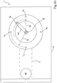
Figure 1 shows a block diagram representing the invention; -
Figures 2a ,2b and2c show a schematic view of the apparatus of the invention. - The invention relates to an apparatus for testing the integrity of mammary tissues comprising one or more antennas transmitting towards the mammary tissue and operating in the microwave band, one or more antennas receiving from the mammary tissue and operating in the microwave band, and a processing unit configured to determine a main parameter representing an electrical discontinuity of the mammary tissue and to generate a signal representing a non-integrity of the mammary tissue.
- With reference to the
figures, 1 indicates overall an apparatus for testing the integrity of mammary tissues according to the present Invention. - In the present description and in the subsequent claims, the term "mammary tissue" will mean the tissue comprising a glandular component, an adipose component, in which the glandular structures are inserted and immersed, and a fibrous supporting component, which generates subdivisions among the various glandular appendages.
- By way of example, the
mammary tissue 2 can display a relative dielectric constant in the range of 1 to 20. - By way of example, the
mammary tissue 2 can have a conductivity comprised between 0 S/m and 1 S/m. - The apparatus according to the invention, as will be clearer hereinafter, is configured to determine the presence of non-integrity within the
mammary tissue 2 based on possible discontinuities in the electrical behaviour of the mammary tissue itself. - In the course of the description, the term "non-integrity" will mean an inhomogeneity in the mammary tissue indicative of anomalous conditions in the composition of the tissue itself.
- In practical terms, the invention allows to identify, within the mass of mammary tissue 2 (assumed to be homogeneous, within certain limits), areas in which the relative dielectric constant and/or the conductivity have significant variations (for example, an increase of at least 25%).
- Preferably, the relative dielectric constant and the conductivity of the mammary tissue are known beforehand, even if in a manner that is not wholly precise.
- With reference to the figures, the apparatus for testing the integrity of mammary tissues 1 comprises a fixed supporting structure or
casing 10 on which amovable frame structure 11 is mounted. - The
movable frame structure 11 comprises a substantially horizontal platform PO. - The apparatus according to the invention comprises a first motor M1 associated with the horizontal platform PO.
- In particular, the first motor M1 is coupled to a
hub 22 passing through the horizontal platform PO. - The fixed supporting
structure 10 is configured to comprise the motor M1 and the electromagnetic transceiver components described below. Preferably, the fixed supportingstructure 10 is configured substantially as a parallelepiped. - The top part of 10 comprises a cup-
shaped recess 20 configured to support themammary tissue 2 to be analyzed. - The apparatus 1 of the invention further comprises a vertical axis AV which is substantially perpendicular to the platform PO.
- According to the invention, the vertical axis AV is associated with a second motor M2 configured to slide a carriage associated with the first platform PO along the axis AV.
- In other words, the positioning of the horizontal platform PO at a predefined height for measuring the mammary tissue is determined by the motor M2.
- The motor M2 rotates a ball screw on which a carriage connected to the horizontal platform slides.
- Alternatively, the positioning of the horizontal platform PO on the vertical axis can be achieved with equivalent mechanical means such as belts, racks, chains etc.
- The initial height position is indicated to the test system by means of a sensor SM2.
- With reference to the figures, the apparatus for testing the integrity of a mammary tissue according to the invention comprises one or more transmission antennas TX.
- These antennas are configured to strike a
mammary tissue 2 with a main electromagnetic field F1. - The antennas Tx are mounted inside the
casing 10. - The antennas Tx are concentric to the
hub 22 and can be mounted on the platform PO. - Preferably, the main electromagnetic field F1 is defined in a band in the microwave frequency interval.
- In particular, the frequencies can be comprised between 0.5 GHz and 4 GHz, more preferably between 1 GHz and 3 GHz.
- Preferably, the
mammary tissue 2 is struck by a plurality of electromagnetic fields coming from different directions. - In the preferred embodiment, the use of one or more transmission antennas TX is envisaged.
- In particular, a plurality of transmission antennas TX can be used for the purpose of generating the aforesaid electromagnetic fields coming from different directions.
- In other words, the transmission antennas TX are configured to generate the main electromagnetic field F1 originating from different positions.
- In one embodiment, use can be made of a single transmission antenna TX, suitably moved in relation to the
mammary tissue 2 so as to assume different positions over time and thus strike themammary tissue 2 with electromagnetic fields coming from different directions. - It is likewise envisaged that several transmission antennas TX can be moved in relation to the
mammary tissue 2. - Advantageously, the transmission antennas TX can both be moved in relation to the
mammary tissue 2, and switched (i.e. driven between on/off conditions) in such a way as to generate the desired electromagnetic fields in the planned directions and time intervals. - Preferably, the
mammary tissue 2 has a conformation with substantially circular sections. - The transmission antennas TX are advantageously positioned around the
mammary tissue 2, preferably at a given height Q1 relative to the base of the mammary tissue to be analyzed. - In other words, the antennas Tx are mounted on first supports b12 projecting from the platform PO.
- The transmission antennas TX can be set at a height Q1 defined according to the mammary tissue to be measured.
- The transmission antennas TX can be distributed around the
mammary tissue 2 over a circumference with a radius R1. - Advantageously the circumferential distribution of the transmission antennas TX, relative to the
mammary tissue 2, can be substantially angularly uniform. Preferably, there are at least three transmission antennas TX, so as to allow to eliminate the so-called transmitter "image" and prevent the latter from undermining the quality of the measurement. - With reference to the figures, the apparatus for testing the integrity of a mammary tissue according to the invention comprises one or more reception antennas RX configured to pick up a reflected electromagnetic field F2 corresponding to the transmitted field F1.
- These antennas Rx are mounted inside the casing 12.
- The antennas Rx are rotatably associated with the
hub 22 by means of arms b21. - In other words, the arms b21 rotating around the
hub 22 bring about a rotation of the antennas RX in a circular pattern with a radius R2. - The measurement can take place using one or more reception antennas RX. In one embodiment, use can be made of a single reception antenna RX, suitably moved so as to assume different positions over time around the
mammary tissue 2. - It is likewise envisaged that a greater number of reception antennas RX can be moved in relation to the
mammary tissue 2. - As for the transmission antennas, the reception antennas RX can advantageously be positioned at a given height Q1.
- In other words, the antennas Rx are mounted on second supports b22 projecting from the arms b21.
- In the case of the reception antennas RX as well, the height Q1 is defined as a function of the mammary tissue to be measured.
- Preferably, the reception antennas RX and transmission antennas TX are positioned at the same height Q1.
- Preferably, the antennas Tx and Rx are both positioned substantially at a height Q1 equal to half the height of the
mammary tissue 2. - Conveniently, the transmission antennas TX are arranged in a more radially external position than the reception antennas RX, relative to the
mammary tissue 2. This position of the antennas is optimal for applying Huygens' principle to calculate the electromagnetic field within themammary tissue 2, which will be explained below. In fact, said position of the antennas ensures the possibility of measuring the electromagnetic field on a closed external surface substantially in contact with themammary tissue 2 to be analyzed. - In practical terms, the transmission antennas TX are positioned at a greater distance from the
mammary tissue 2, i.e. at the distance R1, than the reception antennas RX, which are at a distance R2. - Preferably, the transmission antennas TX are at a certain distance from the object, whereas the reception antennas are in the immediate proximity of (nearly in contact with) the
mammary tissue 2 and positioned on a rotating support with, for example, an angular resolution of nine degrees. - The dimension of the arm b21 determines the respective radius R2. In one embodiment, it can also be assumed to be variable as a function of the dimensions of the
mammary tissue 2 to be measured. - The electrical connection between the rotating antenna Rx and the receiving device is ensured by means of a coaxial rotary joint.
- As an alternative to the rotary joint, the connection can be made by means of a flexible spiral cable and with reversal movements of the direction of rotation every 360 degrees.
- The zero starting point of rotation is indicated to the control system by means of a sensor SM1.
- Preferably, four transmitting antennas Tx1, Tx2, Tx3, Tx4 are fixed to the horizontal platform Po, at a distance equal to the radius R1 greater than R2. In a preferred embodiment, the number of antennas Tx is 3.
- In other embodiments, this number can be greater than or equal to 4.
- The antennas (four in this case) are positioned on circumferential arcs equal to 90 degrees with a radius R1, and are connected to the receiving device by means of a coaxial switch which determines the activation sequence thereof. In one variant, as a replacement for the fixed antennas TX, it is possible to put a single antenna TX which is positioned by a motor M3, not shown in the figure, and is coupled with or replaces the first motor M1, in the circumferential arc established by the measuring sequence.
- In particular, the motor M3 is coupled with a hub 21 (not shown in the figure) which is concentric to the
hub 22 and passes through the horizontal platform PO. - The antenna TX is rotatably associated with the hub 21 by means of the arm b11.
- The system for positioning the antenna TX pivots on the hub 21 which is concentric to the
hub 22 of the antenna Rx. - The zero starting point of rotation is indicated to the control system by means of a sensor SM3.
- Preferably, the transmission and reception antennas are isolated from the remaining part of the structure by means of a coating made of microwave absorbing material.
- With particular reference to
figure 1 , the apparatus for testing the integrity of a mammary tissue comprises aprocessing unit 3 configured to process parameters representing the electromagnetic fields F1 and F2. - In general it should be noted that in the present context and in the subsequent claims, the
processing unit 3 is presented as divided into distinct functional modules (memory modules or operating modules) solely for the purpose of describing the functions of the unit itself in a clear and complete manner. - In reality, the
processing unit 3 can consist of a single electronic device (e.g. a PC, a notebook, or the like), duly programmed to carry out the described functions, and the different modules can correspond to hardware entities and/or to routine software belonging to the programmed device. - Alternatively, or in addition, the functions can be performed by a plurality of electronic devices over which the aforesaid functional modules can be distributed.
- The
processing unit 3 can moreover rely on one or more processors to execute the instructions contained in the memory modules. - Furthermore, the aforesaid functional modules can be distributed over different local or remote computers based on the architecture of the network they are connected to.
- According to the invention, the
processing unit 3 comprises afirst operating module 4 configured to determine, as a function of the reflected electromagnetic field F2, a main parameter MP representing an electrical discontinuity of themammary tissue 2. - As a function of the main parameter MP, it is thus possible to establish whether there is a non-integrity within the
mammary tissue 2. - In other words, as a function of the main parameter MP it is possible to establish whether there is an anomaly in the composition of the
mammary tissue 2. - In still other words, based on the main parameter MP, it is possible to establish whether there is an inhomogeneity in the
mammary tissue 2. - According to the invention, the
processing unit 3 comprises asecond operating module 5 configured to generate, as a function of the main parameter MP, a signal S representing a non-integrity 2a of themammary tissue 2. - The signal S can be generated by the
operating module 5, for example, and will output (for example via a screen or monitor) a value representing the mere presence, or also the position, of the non-integrity of themammary tissue 2. - Advantageously, by exploiting the technical features of the invention it is also possible to determine the position of the non-integrity within the
mammary tissue 2. - With the procedure of the invention, the value of the S/C ratio within the mammary tissue is approximately 8 dB, i.e. about double the value obtained with the technique that exploits focusing algorithms.
- Going into further detail, the invention is based on the following considerations.
- Let us consider a
mammary tissue 2 having substantially circular sections; let us assume that the radius of the section corresponding to the height Q1 is a0. The value of a0 can vary between 2 and 10 cm. - The
mammary tissue 2 is illuminated by at least one antenna tx operating in the given frequency band. - It is assumed that we know the dielectric constant and conductivity of the
mammary tissue 2 beforehand; this information does not necessarily have to be particularly accurate. - It is assumed, moreover, that if the
mammary tissue 2 displays homogeneous behaviour in terms of dielectric constant and conductivity, it can be considered intact, i.e. free of detectable pathologies. - In contrast, if discontinuities were to be found, the assessment as to integrity would change and cases could occur in which anomalies are present.
- Let us suppose that the field transmitted by Tx is measured in the points rxnp≡(a0 ,φnp ) with np=1,...,NPT located on the surface. In greater detail, the transfer function is measured in modulus and phase via a VNA or equivalent architecture, also called s12. The transfer function is measured in the operating band over a number NF of discrete frequencies fi. Exploiting Huygens' principle, the field within the
mammary tissue 2 is calculated. In particular, thefirst operating module 4 is further configured to calculate, as a function of the reflected electromagnetic field F2 and exploiting Huygens' principle, an electromagnetic field within themammary tissue 2 and is further configured to determine, as a function of the electromagnetic field calculated within the mammary tissue, the main parameter MP representing the electrical discontinuity of themammary tissue 2. The use of Huygens' principle ensures a higher signal-to-clutter ratio as compared to the known techniques and a better resolution, other parameters being equal. Moreover, the application of Huygens' principle does not require the use of iterative algorithms and is thus numerically more stable. Finally, the use of Huygens' principle does not require synchronization between the transmission antennas TX and reception antennas RX: as a result, the apparatus 1 is simpler and more cheap to make. - If the
mammary tissue 2 contains a non-integrity, the image I will show a peak signal in the site corresponding to the position of the non-integrity itself. The peak is preferably characterized by an S/C ratio of around 8 dB, obtained using a band comprised between 1 GHz and 3 GHz, and at least three transmission antennas TX. - In order to remove possible artifacts, time-domain filtering can be used in an appropriate manner.
- Going into greater detail, the following steps can be carried out:
- one starts from the transfer function in the frequency domain; said signal could contain contributions reflected/scattered by the environment wherein the measurement is performed, which are thus "external" to the mammary tissue being analyzed;
- one passes into the time domain via an inverse Fourier transform; possible "external" contributions (i.e. reflected/scattered by the environment where the measurement is performed) will show themselves with a greater delay than the "internal" contributions (i.e. reflected/scattered by the mammary tissue being analyzed);
- the time-domain signal is multiplied by a time window in order to filter out the "external" components;
- one returns to the frequency domain via a Fourier transform.
- The transfer function can be obtained at NF=625 discrete frequencies between 1 GHz and 3 GHz.
- The field can be measured in Npt=40 angularly equidistant points on the surface of the
mammary tissue 2. - A total of M=4 data series (m=1...4) are obtained by varying the position of the transmission antenna by steps of 90°.
- Advantageously, the frequency band, NF, Npt, M can be varied.
- In order to perform a 3D imaging operation, the procedure disclosed and claimed can be repeated a number of times, positioning the antennas at different heights along the height, i.e. the longitudinal extent, of the mammary tissue. In this way it is be possible to obtain a three-dimensional image of the non-integrity 2a of the
mammary tissue 2, thus enabling the spatial extent of the anomalous condition of the composition of themammary tissue 2 to be observed and thus improving the ability to quantify the anomalous condition itself. - The
processing unit 3 can further comprise apositioning module 6. - The
positioning module 6 is configured to determine the dimensions of the arms 21 as a function of the mammary tissue to be measured. - In other words, the apparatus of the invention can comprise a sensor S4 positioned in proximity to the
cup 20 and configured to measure the dimensions d1 of themammary tissue 2. - The
positioning module 6 receives the value of the dimensions d1 as input and determines a corresponding variation of the arms b21. - The
processing unit 3 further comprises a second positioning module 7. - The second positioning module 7 is configured to move the supporting platform PO along the vertical axis AV.
- In other words, the second positioning module 7 is configured to drive the second motor M2 to position the horizontal platform PO at a predefined height Q1 for measuring the mammary tissue.
- The initial height is indicated to the control system by means of the previously described sensor SM2.
- The
processing unit 3 according to the invention further comprises acontrol module 8. - The
control module 8 is configured to control one or more transmission antennas (TX) and/or one or more reception antennas (RX) so as to switch them between an activation condition and a deactivation condition. - The technical effect achieved is an optimal measurement of the
mammary tissue 2 to be tested. - The invention achieves important advantages.
- Firstly, the apparatus according to the invention makes it possible to determine, in a non-invasive and simultaneously reliable manner, the presence of non-integrity in a
mammary tissue 2. - Furthermore, in a non-invasive manner and at the same time with a high degree of reliability, the apparatus according to the invention makes it possible to determine the position of the non-integrity within the
mammary tissue 2. - Additionally, the apparatus allows an optimal positioning of the electromagnetic transceiving antennas so as to ensure an optimal test of the mammary tissue.
Claims (13)
- Apparatus for testing the integrity of a mammary tissue comprising:- a housing comprising a cup-shaped recess (20) configured to support the mammary tissue (2) to be analyzed;- a fixed supporting structure (10) and a movable frame structure (11) mounted thereon; the movable frame structure comprising a substantially horizontal platform (PO);- one or more transmission antennas (TX) mounted to the platform (PO) and operating in the band of microwaves configured to strike said mammary tissue (2) with a main electromagnetic field (F1);- one or more reception antennas (RX) operating in the same band and configured to pick up a corresponding reflected electromagnetic field (F2);- a processing unit (3) comprising:the apparatus further comprising:• a first operating module (4) configured to determine, as a function of said reflected electromagnetic field (F2), a main parameter (MP) representing an electrical discontinuity of said mammary tissue (2);• a second operating module (5) configured to generate, as a function of said main parameter (MP), a signal (S) representing a non-integrity (2a) of said mammary tissue (2); wherein said one or more transmission antennas (TX) are mounted on first supports (b12) projecting from the platform (PO);- an hub (22) passing through the horizontal platform and a motor (M1) coupled to the hub (22),- at least one arm (b21) comprising a support (b22) projecting from the arm, with the one or more reception antennas (RX) being mounted on said support, wherein the arm (b21) is adapted to rotate around the hub (22) to bring about a rotation of the one or more reception antennas (RX); wherein said one or more transmission antennas (TX) are arranged in a more radially external position than said one or more reception antennas (RX), with respect to said mammary tissue (2),
wherein the one or more reception antennas (RX) are configured to be rotatably moved, in such a way as to pick up said reflected electromagnetic field (F2) in different directions;- a coaxial rotary joint for electrically connecting the one or more rotating reception antennas to the processing unit;- and a motor (M2) for positioning of the horizontal platform (PO) at a predefined height such that said one or more transmission antennas (TX) and said one or more reception antennas (RX) can be repeatedly positioned at different heights along the height of said mammary tissue. - Apparatus according to claim 1, wherein the one or more transmission antennas (TX) and the one or more reception antennas (RX) are isolated from the remaining part of the structure by means of a coating of microwave absorbing material.
- Apparatus according to any of the previous claims, wherein the first operating module (4) is further configured to time-domain filter said reflected electromagnetic field (F2), in order to remove contributions reflected/scattered by the measurement environment.
- Apparatus according to any of the previous claims, wherein the first operating module (4) is further configured to:▪ calculate, as a function of said reflected electromagnetic field (F2) and exploiting the Huygens' principle, an electromagnetic field within the mammary tissue;▪ determine, as a function of the electromagnetic field calculated within the mammary tissue, said main parameter (MP) representing the electrical discontinuity of the mammary tissue (2).
- Apparatus according to any of the previous claims, wherein said one or more transmission antennas (TX) are configured to generate said main electromagnetic field (F1) originating from different positions.
- Apparatus according to claim 5, wherein said one or more transmission antennas (TX) are each positioned in a respective position, for the emission of said main electromagnetic field (F1).
- Apparatus according to claims 5 or 6, wherein said one or more transmission antennas (Tx) are configured to be- moved in relation to said mammary tissue (2) so as to emit said main electromagnetic field (F1) from said different positions.
- Apparatus according to claims 6 or 7, wherein the one or more transmission antennas (Tx) are configured to emit said radiation in a predetermined frequency interval.
- Apparatus according to any of the claims from 5 to 8, wherein said one or more transmission antennas (Tx) are positioned in at least three different positions.
- Apparatus according to any of the claims from to 8, wherein said mammary tissue (2) has sections which are substantially circular, and said one or more transmission antennas (TX) are positioned at a given height relative to the base of said tissue.
- Apparatus according to claim 10, wherein said mammary tissue (2) has sections that are substantially circular, and said one or more reception antennas (RX) are positioned at a given height relative to the base of said tissue.
- Apparatus according to claims 10 or 11, wherein said one or more transmission antennas (TX) and said one or more reception antennas (RX) are positioned at the same height (Q1) relative to the base of said tissue.
- Apparatus according to any of the preceding claims, wherein said processing unit (3) comprises a control module (8) configured to control of said one or more transmission antennas (TX) and/or said one or more reception antennas (RX) so as to switch them between an activation condition and a deactivation condition.
Priority Applications (1)
| Application Number | Priority Date | Filing Date | Title |
|---|---|---|---|
| PL13801733T PL2903511T3 (en) | 2012-09-18 | 2013-09-16 | Apparatus for testing the integrity of mammary tissues |
Applications Claiming Priority (2)
| Application Number | Priority Date | Filing Date | Title |
|---|---|---|---|
| IT001542A ITMI20121542A1 (en) | 2012-09-18 | 2012-09-18 | APPARATUS FOR THE INTEGRITY CONTROL OF MAMMARY TEXTILES |
| PCT/IB2013/058573 WO2014045181A1 (en) | 2012-09-18 | 2013-09-16 | Apparatus for testing the integrity of mammary tissues |
Publications (2)
| Publication Number | Publication Date |
|---|---|
| EP2903511A1 EP2903511A1 (en) | 2015-08-12 |
| EP2903511B1 true EP2903511B1 (en) | 2019-06-12 |
Family
ID=47278394
Family Applications (1)
| Application Number | Title | Priority Date | Filing Date |
|---|---|---|---|
| EP13801733.0A Active EP2903511B1 (en) | 2012-09-18 | 2013-09-16 | Apparatus for testing the integrity of mammary tissues |
Country Status (7)
| Country | Link |
|---|---|
| US (1) | US10349863B2 (en) |
| EP (1) | EP2903511B1 (en) |
| CN (1) | CN104661591B (en) |
| ES (1) | ES2744329T3 (en) |
| IT (1) | ITMI20121542A1 (en) |
| PL (1) | PL2903511T3 (en) |
| WO (1) | WO2014045181A1 (en) |
Families Citing this family (3)
| Publication number | Priority date | Publication date | Assignee | Title |
|---|---|---|---|---|
| FR3006576B1 (en) | 2013-06-06 | 2016-08-19 | Satimo Ind | MEDICAL EMITTING / RECEPTION MICROWAVE IMAGING SYSTEM |
| RU2578298C1 (en) * | 2014-11-24 | 2016-03-27 | Самсунг Электроникс Ко., Лтд. | Ultra-bandwidth device for determining profile of living organism tissue layers and corresponding method |
| EP3781932B1 (en) * | 2018-04-17 | 2023-11-29 | Ubt S.R.L. | Device for microwave measurement of a dielectric discontinuity of a material |
Family Cites Families (6)
| Publication number | Priority date | Publication date | Assignee | Title |
|---|---|---|---|---|
| US4831384A (en) * | 1988-05-31 | 1989-05-16 | Tecom Industries Incorporated | Polarization-sensitive receiver for microwave signals |
| EP0984722A4 (en) * | 1997-05-23 | 2004-04-14 | Carolinas Heart Inst | Electromagnetical imaging and therapeutic (emit) systems |
| US20040077943A1 (en) * | 2002-04-05 | 2004-04-22 | Meaney Paul M. | Systems and methods for 3-D data acquisition for microwave imaging |
| US7771360B2 (en) * | 2003-04-09 | 2010-08-10 | Techniscan, Inc. | Breast scanning system |
| US7809427B2 (en) * | 2005-02-11 | 2010-10-05 | Wisconsin Alumni Research Foundation | Time domain inverse scattering techniques for use in microwave imaging |
| US20110130656A1 (en) * | 2009-11-30 | 2011-06-02 | Seong-Ho Son | Microwave image reconstruction apparatus and method |
-
2012
- 2012-09-18 IT IT001542A patent/ITMI20121542A1/en unknown
-
2013
- 2013-09-16 EP EP13801733.0A patent/EP2903511B1/en active Active
- 2013-09-16 US US14/429,032 patent/US10349863B2/en active Active
- 2013-09-16 ES ES13801733T patent/ES2744329T3/en active Active
- 2013-09-16 WO PCT/IB2013/058573 patent/WO2014045181A1/en active Application Filing
- 2013-09-16 CN CN201380047669.XA patent/CN104661591B/en active Active
- 2013-09-16 PL PL13801733T patent/PL2903511T3/en unknown
Non-Patent Citations (1)
| Title |
|---|
| None * |
Also Published As
| Publication number | Publication date |
|---|---|
| CN104661591A (en) | 2015-05-27 |
| US20150230725A1 (en) | 2015-08-20 |
| US10349863B2 (en) | 2019-07-16 |
| ITMI20121542A1 (en) | 2014-03-19 |
| WO2014045181A9 (en) | 2015-05-14 |
| EP2903511A1 (en) | 2015-08-12 |
| ES2744329T3 (en) | 2020-02-24 |
| WO2014045181A1 (en) | 2014-03-27 |
| CN104661591B (en) | 2018-11-16 |
| PL2903511T3 (en) | 2019-12-31 |
Similar Documents
| Publication | Publication Date | Title |
|---|---|---|
| US20170199134A1 (en) | Imaging using reconfigurable antennas | |
| WO1998052464A1 (en) | Electromagnetical imaging and therapeutic (emit) systems | |
| Ruvio et al. | Breast cancer detection using interferometric MUSIC: Experimental and numerical assessment | |
| CN104473617A (en) | Organism tissue detecting device, system and method | |
| Zamani et al. | Boundary estimation of imaged object in microwave medical imaging using antenna resonant frequency shift | |
| Tiang et al. | Radar sensing featuring biconical antenna and enhanced delay and sum algorithm for early stage breast cancer detection | |
| Khalesi et al. | Free-space operating microwave imaging device for bone lesion detection: A phantom investigation | |
| EP2903511B1 (en) | Apparatus for testing the integrity of mammary tissues | |
| JP2016529937A (en) | Medical imaging system for microwave radiation / reception | |
| Sohani et al. | Microwave imaging for stroke detection: validation on head-mimicking phantom | |
| JP2014198067A (en) | Diagnostic system | |
| Salleh et al. | Development of antipodal Vivaldi antenna for microwave brain stroke imaging system | |
| Wang et al. | Imaging of 3-D dielectric objects using far-field holographic microwave imaging technique | |
| Nguyen et al. | High frequency breast imaging: Experimental analysis of tissue phantoms | |
| Khalesi et al. | Skin cancer detection through microwaves: validation on phantom measurements | |
| Maffongelli et al. | Design and experimental test of a microwave system for quantitative biomedical imaging | |
| Jafari et al. | Co-polarised and cross-polarised antenna arrays for breast, cancer detection | |
| Koutsoupidou et al. | Towards a microwave imaging prototype based on the DBIM-TwIST algorithm and a custom-made transceiver system | |
| Solimene et al. | An incoherent radar imaging system for medical applications | |
| Rubæk et al. | A contrast source inversion algorithm formulated using the log-phase formulation | |
| Moll et al. | Time-difference-of-arrival imaging for ultra-wideband microwave mammography | |
| Sohani et al. | An analytically based approach for evaluating the impact of the noise on the microwave imaging detection | |
| Khor et al. | Investigations into breast cancer detection using ultra wide band microwave radar technique | |
| Anjit et al. | Microwave imaging solutions for medical imaging using re-weighted basic pursuit algorithm | |
| Akıncı et al. | Experimental comparison of qualitative inverse scattering methods |
Legal Events
| Date | Code | Title | Description |
|---|---|---|---|
| PUAI | Public reference made under article 153(3) epc to a published international application that has entered the european phase |
Free format text: ORIGINAL CODE: 0009012 |
|
| 17P | Request for examination filed |
Effective date: 20150415 |
|
| AK | Designated contracting states |
Kind code of ref document: A1 Designated state(s): AL AT BE BG CH CY CZ DE DK EE ES FI FR GB GR HR HU IE IS IT LI LT LU LV MC MK MT NL NO PL PT RO RS SE SI SK SM TR |
|
| AX | Request for extension of the european patent |
Extension state: BA ME |
|
| DAX | Request for extension of the european patent (deleted) | ||
| STAA | Information on the status of an ep patent application or granted ep patent |
Free format text: STATUS: EXAMINATION IS IN PROGRESS |
|
| GRAP | Despatch of communication of intention to grant a patent |
Free format text: ORIGINAL CODE: EPIDOSNIGR1 |
|
| STAA | Information on the status of an ep patent application or granted ep patent |
Free format text: STATUS: GRANT OF PATENT IS INTENDED |
|
| 17Q | First examination report despatched |
Effective date: 20190115 |
|
| INTG | Intention to grant announced |
Effective date: 20190213 |
|
| RIN1 | Information on inventor provided before grant (corrected) |
Inventor name: RASPA, RICCARDO LUIGI Inventor name: TIBERI, GIANLUIGI Inventor name: RASPA, GIOVANNI |
|
| GRAS | Grant fee paid |
Free format text: ORIGINAL CODE: EPIDOSNIGR3 |
|
| GRAA | (expected) grant |
Free format text: ORIGINAL CODE: 0009210 |
|
| STAA | Information on the status of an ep patent application or granted ep patent |
Free format text: STATUS: THE PATENT HAS BEEN GRANTED |
|
| AK | Designated contracting states |
Kind code of ref document: B1 Designated state(s): AL AT BE BG CH CY CZ DE DK EE ES FI FR GB GR HR HU IE IS IT LI LT LU LV MC MK MT NL NO PL PT RO RS SE SI SK SM TR |
|
| REG | Reference to a national code |
Ref country code: GB Ref legal event code: FG4D |
|
| REG | Reference to a national code |
Ref country code: CH Ref legal event code: EP |
|
| REG | Reference to a national code |
Ref country code: AT Ref legal event code: REF Ref document number: 1141516 Country of ref document: AT Kind code of ref document: T Effective date: 20190615 |
|
| REG | Reference to a national code |
Ref country code: DE Ref legal event code: R096 Ref document number: 602013056592 Country of ref document: DE |
|
| REG | Reference to a national code |
Ref country code: IE Ref legal event code: FG4D |
|
| REG | Reference to a national code |
Ref country code: RO Ref legal event code: EPE |
|
| REG | Reference to a national code |
Ref country code: CH Ref legal event code: NV Representative=s name: BUGNION S.A., CH |
|
| REG | Reference to a national code |
Ref country code: NL Ref legal event code: FP |
|
| REG | Reference to a national code |
Ref country code: SE Ref legal event code: TRGR |
|
| REG | Reference to a national code |
Ref country code: LT Ref legal event code: MG4D |
|
| PG25 | Lapsed in a contracting state [announced via postgrant information from national office to epo] |
Ref country code: AL Free format text: LAPSE BECAUSE OF FAILURE TO SUBMIT A TRANSLATION OF THE DESCRIPTION OR TO PAY THE FEE WITHIN THE PRESCRIBED TIME-LIMIT Effective date: 20190612 Ref country code: FI Free format text: LAPSE BECAUSE OF FAILURE TO SUBMIT A TRANSLATION OF THE DESCRIPTION OR TO PAY THE FEE WITHIN THE PRESCRIBED TIME-LIMIT Effective date: 20190612 Ref country code: LT Free format text: LAPSE BECAUSE OF FAILURE TO SUBMIT A TRANSLATION OF THE DESCRIPTION OR TO PAY THE FEE WITHIN THE PRESCRIBED TIME-LIMIT Effective date: 20190612 Ref country code: NO Free format text: LAPSE BECAUSE OF FAILURE TO SUBMIT A TRANSLATION OF THE DESCRIPTION OR TO PAY THE FEE WITHIN THE PRESCRIBED TIME-LIMIT Effective date: 20190912 Ref country code: HR Free format text: LAPSE BECAUSE OF FAILURE TO SUBMIT A TRANSLATION OF THE DESCRIPTION OR TO PAY THE FEE WITHIN THE PRESCRIBED TIME-LIMIT Effective date: 20190612 |
|
| PG25 | Lapsed in a contracting state [announced via postgrant information from national office to epo] |
Ref country code: LV Free format text: LAPSE BECAUSE OF FAILURE TO SUBMIT A TRANSLATION OF THE DESCRIPTION OR TO PAY THE FEE WITHIN THE PRESCRIBED TIME-LIMIT Effective date: 20190612 Ref country code: BG Free format text: LAPSE BECAUSE OF FAILURE TO SUBMIT A TRANSLATION OF THE DESCRIPTION OR TO PAY THE FEE WITHIN THE PRESCRIBED TIME-LIMIT Effective date: 20190912 Ref country code: GR Free format text: LAPSE BECAUSE OF FAILURE TO SUBMIT A TRANSLATION OF THE DESCRIPTION OR TO PAY THE FEE WITHIN THE PRESCRIBED TIME-LIMIT Effective date: 20190913 Ref country code: RS Free format text: LAPSE BECAUSE OF FAILURE TO SUBMIT A TRANSLATION OF THE DESCRIPTION OR TO PAY THE FEE WITHIN THE PRESCRIBED TIME-LIMIT Effective date: 20190612 |
|
| REG | Reference to a national code |
Ref country code: AT Ref legal event code: MK05 Ref document number: 1141516 Country of ref document: AT Kind code of ref document: T Effective date: 20190612 |
|
| PG25 | Lapsed in a contracting state [announced via postgrant information from national office to epo] |
Ref country code: PT Free format text: LAPSE BECAUSE OF FAILURE TO SUBMIT A TRANSLATION OF THE DESCRIPTION OR TO PAY THE FEE WITHIN THE PRESCRIBED TIME-LIMIT Effective date: 20191014 Ref country code: CZ Free format text: LAPSE BECAUSE OF FAILURE TO SUBMIT A TRANSLATION OF THE DESCRIPTION OR TO PAY THE FEE WITHIN THE PRESCRIBED TIME-LIMIT Effective date: 20190612 Ref country code: AT Free format text: LAPSE BECAUSE OF FAILURE TO SUBMIT A TRANSLATION OF THE DESCRIPTION OR TO PAY THE FEE WITHIN THE PRESCRIBED TIME-LIMIT Effective date: 20190612 Ref country code: EE Free format text: LAPSE BECAUSE OF FAILURE TO SUBMIT A TRANSLATION OF THE DESCRIPTION OR TO PAY THE FEE WITHIN THE PRESCRIBED TIME-LIMIT Effective date: 20190612 Ref country code: SK Free format text: LAPSE BECAUSE OF FAILURE TO SUBMIT A TRANSLATION OF THE DESCRIPTION OR TO PAY THE FEE WITHIN THE PRESCRIBED TIME-LIMIT Effective date: 20190612 |
|
| REG | Reference to a national code |
Ref country code: ES Ref legal event code: FG2A Ref document number: 2744329 Country of ref document: ES Kind code of ref document: T3 Effective date: 20200224 |
|
| PG25 | Lapsed in a contracting state [announced via postgrant information from national office to epo] |
Ref country code: IS Free format text: LAPSE BECAUSE OF FAILURE TO SUBMIT A TRANSLATION OF THE DESCRIPTION OR TO PAY THE FEE WITHIN THE PRESCRIBED TIME-LIMIT Effective date: 20191012 Ref country code: SM Free format text: LAPSE BECAUSE OF FAILURE TO SUBMIT A TRANSLATION OF THE DESCRIPTION OR TO PAY THE FEE WITHIN THE PRESCRIBED TIME-LIMIT Effective date: 20190612 |
|
| REG | Reference to a national code |
Ref country code: DE Ref legal event code: R097 Ref document number: 602013056592 Country of ref document: DE |
|
| PLBE | No opposition filed within time limit |
Free format text: ORIGINAL CODE: 0009261 |
|
| STAA | Information on the status of an ep patent application or granted ep patent |
Free format text: STATUS: NO OPPOSITION FILED WITHIN TIME LIMIT |
|
| PG25 | Lapsed in a contracting state [announced via postgrant information from national office to epo] |
Ref country code: DK Free format text: LAPSE BECAUSE OF FAILURE TO SUBMIT A TRANSLATION OF THE DESCRIPTION OR TO PAY THE FEE WITHIN THE PRESCRIBED TIME-LIMIT Effective date: 20190612 |
|
| 26N | No opposition filed |
Effective date: 20200313 |
|
| PG25 | Lapsed in a contracting state [announced via postgrant information from national office to epo] |
Ref country code: MC Free format text: LAPSE BECAUSE OF FAILURE TO SUBMIT A TRANSLATION OF THE DESCRIPTION OR TO PAY THE FEE WITHIN THE PRESCRIBED TIME-LIMIT Effective date: 20190612 Ref country code: SI Free format text: LAPSE BECAUSE OF FAILURE TO SUBMIT A TRANSLATION OF THE DESCRIPTION OR TO PAY THE FEE WITHIN THE PRESCRIBED TIME-LIMIT Effective date: 20190612 Ref country code: IS Free format text: LAPSE BECAUSE OF FAILURE TO SUBMIT A TRANSLATION OF THE DESCRIPTION OR TO PAY THE FEE WITHIN THE PRESCRIBED TIME-LIMIT Effective date: 20200224 |
|
| PG2D | Information on lapse in contracting state deleted |
Ref country code: IS |
|
| PG25 | Lapsed in a contracting state [announced via postgrant information from national office to epo] |
Ref country code: LU Free format text: LAPSE BECAUSE OF NON-PAYMENT OF DUE FEES Effective date: 20190916 |
|
| PG25 | Lapsed in a contracting state [announced via postgrant information from national office to epo] |
Ref country code: CY Free format text: LAPSE BECAUSE OF FAILURE TO SUBMIT A TRANSLATION OF THE DESCRIPTION OR TO PAY THE FEE WITHIN THE PRESCRIBED TIME-LIMIT Effective date: 20190612 |
|
| PG25 | Lapsed in a contracting state [announced via postgrant information from national office to epo] |
Ref country code: MT Free format text: LAPSE BECAUSE OF FAILURE TO SUBMIT A TRANSLATION OF THE DESCRIPTION OR TO PAY THE FEE WITHIN THE PRESCRIBED TIME-LIMIT Effective date: 20190612 Ref country code: HU Free format text: LAPSE BECAUSE OF FAILURE TO SUBMIT A TRANSLATION OF THE DESCRIPTION OR TO PAY THE FEE WITHIN THE PRESCRIBED TIME-LIMIT; INVALID AB INITIO Effective date: 20130916 |
|
| PG25 | Lapsed in a contracting state [announced via postgrant information from national office to epo] |
Ref country code: MK Free format text: LAPSE BECAUSE OF FAILURE TO SUBMIT A TRANSLATION OF THE DESCRIPTION OR TO PAY THE FEE WITHIN THE PRESCRIBED TIME-LIMIT Effective date: 20190612 |
|
| PGFP | Annual fee paid to national office [announced via postgrant information from national office to epo] |
Ref country code: TR Payment date: 20230918 Year of fee payment: 11 Ref country code: RO Payment date: 20230918 Year of fee payment: 11 Ref country code: NL Payment date: 20230926 Year of fee payment: 11 Ref country code: IE Payment date: 20230919 Year of fee payment: 11 Ref country code: GB Payment date: 20230926 Year of fee payment: 11 |
|
| PGFP | Annual fee paid to national office [announced via postgrant information from national office to epo] |
Ref country code: SE Payment date: 20230926 Year of fee payment: 11 Ref country code: PL Payment date: 20230915 Year of fee payment: 11 Ref country code: FR Payment date: 20230926 Year of fee payment: 11 Ref country code: DE Payment date: 20230928 Year of fee payment: 11 Ref country code: BE Payment date: 20230926 Year of fee payment: 11 |
|
| PGFP | Annual fee paid to national office [announced via postgrant information from national office to epo] |
Ref country code: ES Payment date: 20231018 Year of fee payment: 11 |
|
| PGFP | Annual fee paid to national office [announced via postgrant information from national office to epo] |
Ref country code: IT Payment date: 20230925 Year of fee payment: 11 Ref country code: CH Payment date: 20231001 Year of fee payment: 11 |