EP2903356A1 - Noeud de réseau et procédés associés - Google Patents
Noeud de réseau et procédés associés Download PDFInfo
- Publication number
- EP2903356A1 EP2903356A1 EP15153819.6A EP15153819A EP2903356A1 EP 2903356 A1 EP2903356 A1 EP 2903356A1 EP 15153819 A EP15153819 A EP 15153819A EP 2903356 A1 EP2903356 A1 EP 2903356A1
- Authority
- EP
- European Patent Office
- Prior art keywords
- power
- user equipment
- cell
- periods
- network node
- Prior art date
- Legal status (The legal status is an assumption and is not a legal conclusion. Google has not performed a legal analysis and makes no representation as to the accuracy of the status listed.)
- Granted
Links
- 238000000034 method Methods 0.000 title claims abstract description 47
- 230000005540 biological transmission Effects 0.000 claims abstract description 130
- 230000023402 cell communication Effects 0.000 claims abstract description 30
- 210000004027 cell Anatomy 0.000 description 291
- 230000009471 action Effects 0.000 description 35
- 230000007704 transition Effects 0.000 description 34
- 238000004891 communication Methods 0.000 description 16
- 238000012545 processing Methods 0.000 description 16
- 230000001771 impaired effect Effects 0.000 description 15
- 230000009467 reduction Effects 0.000 description 10
- 238000010586 diagram Methods 0.000 description 8
- 230000011664 signaling Effects 0.000 description 6
- 230000008859 change Effects 0.000 description 5
- 238000009826 distribution Methods 0.000 description 5
- 239000000969 carrier Substances 0.000 description 4
- 238000001514 detection method Methods 0.000 description 4
- 230000008901 benefit Effects 0.000 description 3
- 238000005516 engineering process Methods 0.000 description 3
- 238000010295 mobile communication Methods 0.000 description 3
- 230000008569 process Effects 0.000 description 3
- 230000007480 spreading Effects 0.000 description 3
- 238000003892 spreading Methods 0.000 description 3
- 238000004590 computer program Methods 0.000 description 2
- 125000004122 cyclic group Chemical group 0.000 description 2
- 230000006735 deficit Effects 0.000 description 2
- 230000006870 function Effects 0.000 description 2
- 230000007774 longterm Effects 0.000 description 2
- 238000005259 measurement Methods 0.000 description 2
- 238000012986 modification Methods 0.000 description 2
- 230000004048 modification Effects 0.000 description 2
- 230000001960 triggered effect Effects 0.000 description 2
- 101100411667 Arabidopsis thaliana RAN4 gene Proteins 0.000 description 1
- 241000700159 Rattus Species 0.000 description 1
- 230000002776 aggregation Effects 0.000 description 1
- 238000004220 aggregation Methods 0.000 description 1
- 238000004458 analytical method Methods 0.000 description 1
- 230000006399 behavior Effects 0.000 description 1
- 230000009028 cell transition Effects 0.000 description 1
- 230000001413 cellular effect Effects 0.000 description 1
- 210000003850 cellular structure Anatomy 0.000 description 1
- 230000001419 dependent effect Effects 0.000 description 1
- 230000000694 effects Effects 0.000 description 1
- 230000002452 interceptive effect Effects 0.000 description 1
- 238000011835 investigation Methods 0.000 description 1
- 230000007246 mechanism Effects 0.000 description 1
- 238000001774 stimulated Raman spectroscopy Methods 0.000 description 1
- 238000003860 storage Methods 0.000 description 1
Images


Classifications
-
- H—ELECTRICITY
- H04—ELECTRIC COMMUNICATION TECHNIQUE
- H04W—WIRELESS COMMUNICATION NETWORKS
- H04W52/00—Power management, e.g. TPC [Transmission Power Control], power saving or power classes
- H04W52/04—TPC
- H04W52/30—TPC using constraints in the total amount of available transmission power
- H04W52/34—TPC management, i.e. sharing limited amount of power among users or channels or data types, e.g. cell loading
- H04W52/346—TPC management, i.e. sharing limited amount of power among users or channels or data types, e.g. cell loading distributing total power among users or channels
-
- H—ELECTRICITY
- H04—ELECTRIC COMMUNICATION TECHNIQUE
- H04W—WIRELESS COMMUNICATION NETWORKS
- H04W52/00—Power management, e.g. TPC [Transmission Power Control], power saving or power classes
- H04W52/04—TPC
- H04W52/18—TPC being performed according to specific parameters
- H04W52/28—TPC being performed according to specific parameters using user profile, e.g. mobile speed, priority or network state, e.g. standby, idle or non transmission
- H04W52/281—TPC being performed according to specific parameters using user profile, e.g. mobile speed, priority or network state, e.g. standby, idle or non transmission taking into account user or data type priority
-
- H—ELECTRICITY
- H04—ELECTRIC COMMUNICATION TECHNIQUE
- H04W—WIRELESS COMMUNICATION NETWORKS
- H04W56/00—Synchronisation arrangements
- H04W56/004—Synchronisation arrangements compensating for timing error of reception due to propagation delay
- H04W56/0045—Synchronisation arrangements compensating for timing error of reception due to propagation delay compensating for timing error by altering transmission time
-
- H—ELECTRICITY
- H04—ELECTRIC COMMUNICATION TECHNIQUE
- H04L—TRANSMISSION OF DIGITAL INFORMATION, e.g. TELEGRAPHIC COMMUNICATION
- H04L25/00—Baseband systems
- H04L25/02—Details ; arrangements for supplying electrical power along data transmission lines
- H04L25/06—Dc level restoring means; Bias distortion correction ; Decision circuits providing symbol by symbol detection
- H04L25/067—Dc level restoring means; Bias distortion correction ; Decision circuits providing symbol by symbol detection providing soft decisions, i.e. decisions together with an estimate of reliability
-
- H—ELECTRICITY
- H04—ELECTRIC COMMUNICATION TECHNIQUE
- H04W—WIRELESS COMMUNICATION NETWORKS
- H04W52/00—Power management, e.g. TPC [Transmission Power Control], power saving or power classes
- H04W52/04—TPC
- H04W52/06—TPC algorithms
- H04W52/14—Separate analysis of uplink or downlink
- H04W52/146—Uplink power control
Definitions
- Embodiments herein relate to a user equipment, a network node and methods therein. In particular, some embodiments herein relate to apply power scaling to uplink transmissions in a multiple cell communications network.
- a radio communications network comprises radio base stations providing radio coverage over at least one respective geographical area forming a cell.
- the cell definition may also incorporate frequency bands used for transmissions, which means that two different cells may cover the same geographical area but using different frequency bands.
- UE User equipments
- eNodeB eNodeB
- the user equipments transmit data over an air or radio interface to the radio base stations in uplink (UL) transmissions and the radio base stations transmit data over an air or radio interface to the user equipments in downlink (DL) transmissions.
- UL uplink
- DL downlink
- LTE uses Discrete Fourier Transform- Spread- Orthogonal Frequency Division Multiplexing (DFTS-OFDM) or Single Carrier-Frequency Division Multiple-Access (SC-FDMA) in the uplink.
- DFTS-OFDM Discrete Fourier Transform- Spread- Orthogonal Frequency Division Multiplexing
- SC-FDMA Single Carrier-Frequency Division Multiple-Access
- PUSCH Physical Uplink Shared Channel
- Bits are encoded, interleaved, scrambled, and transmitted via the SC-FDMA modulator.
- SC-FDMA modulator In the receiver an inverse process happens.
- the receiver typically calculates soft values or soft bits, one for each information bit or sometimes even one for each coded bit, which correspond to likelihoods that a bit is zero or one.
- PUCCH Physical Uplink Control Channel
- PUCCH applies block spreading, i.e. information is spread with spreading sequences over multiple SC-FDMA symbols. This improves coverage since information is transmitted with more energy but also enables multiplexing with others using the same time-frequency resources but different spreading sequences.
- block spreading i.e. information is spread with spreading sequences over multiple SC-FDMA symbols. This improves coverage since information is transmitted with more energy but also enables multiplexing with others using the same time-frequency resources but different spreading sequences.
- the repetitions must be done with the same power; the copy in different SC-FDMA symbol must be transmitted with the same power. If certain SC-FDMA symbols are transmitted with different power orthogonality is impaired.
- SRS Sounding Reference Signals
- eNB radio base station in LTE
- eNodeB information about UL channel state.
- SRSs are transmitted within the last SC-FDMA symbol of a subframe.
- transmissions from different user equipments may be multiplexed into the same SC-FDMA symbol using different frequencies.
- Figure 1 is an Illustration of two user equipments at different distance from the eNB.
- a user equipment far from the eNB called Cell edge UE, needs to start transmission earlier than a user equipment close to the eNodeB.
- This can for example be handled by timing advance of the UL transmissions, which means that a user equipment starts its UL transmission before a nominal time given by the timing of the DL signal received by the user equipment.
- Figure 2 shows timing advance of UL transmissions from the user equipment depending on distance to the eNB.
- a DL transmission transmitted at time T0 from the eNodeB is received by the UE close to the eNodeB at T1.
- the same transmission is received at the cell edge UE at T2.
- the Cell edge UE is transmitting the UL transmission with a timing advance 1.
- the UE close to the eNodeB is transmitting UL transmission with a timing advance 2.
- the UL Timing Advance is maintained by the eNodeB through TA commands sent to the user equipment based on measurements on UL transmissions from that user equipment. Through TA commands, the user equipment is ordered to start its UL transmissions earlier or later. This applies to all UL transmissions except for random access preamble transmissions on Physical Random Access Channel (PRACH).
- PRACH Physical Random Access Channel
- LTE Release-10 specifications have recently been standardized, supporting cell bandwidths up to 20 MHz, which is the maximal LTE Release-8 bandwidth. An LTE Release-10 operation wider than 20 MHz is possible and appear as a number of LTE cells to an LTE Release-10 user equipment.
- CA Carrier Aggregation
- different subframes over the different cells are transmitted with different levels of transmit power or transmission power. Time is defined along a horizontal axis and power is defined along a vertical axis.
- UL cells also referred to as carriers
- multiple TA values are required.
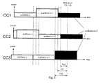
- the eNB must be able to control the UL reception timing of each cell to maintain orthogonality on each cell. Thus, multiple TAs may be needed to control them individually. Since the TA value controls the UL transmission timings different TA values imply misaligned UL subframes, see Figure 3 .
- the end and beginning of subframes on the individual cells are determined by the TA commands; TA1 to TA3 for cell Component Carrier 1 (CC1) to Component Carrier 3 (CC3), respectively, in Figure 3 . Since the eNB knows the TA commands it also knows the end and beginning of subframes. Due to different TA values UL subframes are not time aligned. In the transition period from subframe n + 1 to n + 2 the requested power exceeds the available transmit power since cell CC3 requests higher power but the other two cells have not yet reduced their transmit power. Since the overall signal transmitted by the UE cannot exceed the maximum power, the signal power will be limited by the power amplifier which can lead to unpredictable effects, e.g.
- WO 2011/129716 shows a system where mobile terminal adjusts the transmit power utilized by the mobile terminal for uplink transmissions, and to methods for adjusting the transmit power used by a mobile terminal for one or more RACH procedures.
- An object of embodiments herein is to provide a mechanism that improves the performance in the multiple cell communications network.
- the object is achieved by a method in a user equipment for applying power scaling to uplink transmissions in a multiple cell communications network.
- the user equipment is configured to transmit over a plurality of aggregated cells in uplink to a network node.
- the user equipment receives, from the network node, timing advance information for uplink for one or more aggregated cells of the plurality of aggregated cells.
- the user equipment applies a power scaling to uplink transmissions of at least one aggregated cell out of the plurality of aggregated cells based on the received timing advance information.
- the at least one aggregated cell is associated with the user equipment and is a cell of the multiple cell communications network.
- the object is achieved by a method in a network node for demodulating uplink transmissions from a user equipment in a multiple cell communications network.
- the network node is configured to receive over a plurality of aggregated cells, uplink transmissions from the user equipment.
- the network node transmits, to the user equipment, determined timing advance information for uplink of one or more aggregated cells of the plurality of aggregated cells.
- the network node receives from the user equipment, an uplink transmission of at least one aggregated cell out of the plurality of aggregated cells.
- the network node demodulates the received uplink transmission using weighted soft values in periods in the received uplink transmission. The periods are based on the transmitted timing advance information.
- a user equipment for applying power scaling to uplink transmissions in a multiple cell communications network.
- the user equipment is configured to transmit over a plurality of aggregated cells in uplink to a network node.
- the user equipment comprises a receiver configured to receive, from the network node, timing advance information for uplink for one or more aggregated cells of the plurality of aggregated cells.
- the user equipment comprises an applying circuit configured to apply a power scaling to uplink transmissions of at least one aggregated cell out of the plurality of aggregated cells based on the received timing advance information.
- the at least one aggregated cell is associated with the user equipment and is a cell of the multiple cell communications network.
- a network node for demodulating uplink transmissions from a user equipment in a multiple cell communications network.
- the network node is configured to receive over a plurality of aggregated cells uplink transmissions from the user equipment.
- the network node comprises a transmitter configured to transmit, to the user equipment, determined timing advance information for uplink of one or more aggregated cells of the plurality of aggregated cells.
- the network node comprises a receiver configured to receive, from the user equipment, an uplink transmission of at least one aggregated cell out of the plurality of aggregated cells.
- the network node comprises a demodulating circuit configured to demodulate the received uplink transmission using weighted soft values in periods in the received uplink transmission. The periods are based on the transmitted timing advance information.
- the user equipment behavior becomes predictable. Since power scaling is done only over parts of the subframe performance, impairment is also less compared to the case if the complete subframe would be scaled. Protection of a certain cell e.g. a cell carrying critical information, also protects critical control signaling improving performance and robustness of the connection.
- FIG 4 is a schematic overview depicting a multiple cell communications network.
- the multiple cell communications network may comprise a Universal Mobile Telecommunications System (UMTS), which is a third generation mobile communication system that evolved from the second generation (2G) GSM.
- UMTS terrestrial radio access network UTRAN
- RAN Radio Access Network
- 3GPP Third Generation Partnership Project
- telecommunications suppliers propose and agree upon standards for third generation networks and UTRAN specifically, and investigate enhanced data rate and radio capacity.
- EPS Evolved Packet System
- the EPS comprises an Evolved Universal Terrestrial Radio Access Network (E-UTRAN), also known as the Long Term Evolution (LTE) radio access, and the Evolved Packet Core (EPC), also known as System Architecture Evolution (SAE) core network.
- E-UTRAN/LTE is a variant of a 3GPP radio access technology wherein the radio base station is directly connected to the EPC core network rather than to a Radio Network Controller (RNC).
- RNC Radio Network Controller
- the functions of a RNC are distributed between the radio base stations, e.g., eNodeBs in LTE, and the core network.
- the Radio Access Network (RAN) of an EPS system has an essentially "flat" architecture comprising radio base stations without reporting to RNCs.
- the multiple cell communications network may thus be LTE, LTE-Advanced, WCDMA, GSM/EDGE, WiMax, or UMB, just to mention a few possible implementations.
- Each cell may be served or provided by a network node 800 and/or by e.g. remote radio units (RRU), a first RRU 801 and a second RRU 802 connected to the network node 800.
- RRU remote radio units
- the RRU are transmitters and/or receivers that may be geographically separated from the network node 800.
- the cells may alternatively be provided by different network nodes, e.g. relays, respectively.
- the network node 800 serves a first cell 41, which may be exemplified herein as a Primary Cell or a Component Carrier 1
- the first RRU 801 serves a second cell 42, which may be exemplified herein as a Secondary Cell 1 or a Component Carrier 2
- the second RRU 802 serves a third cell 43, which may be exemplified herein as a Secondary Cell 2 or a Component Carrier 3.
- a cell is associated with the network node 800.
- the network node 800 may also be referred to as a radio node, radio base station, radio network node or eNodeB in the example embodiment description, and comprises in a general sense any node transmitting radio signals used for measurements, e.g., eNodeB, macro/micro/pico base station, home eNodeB, relay, beacon device, or repeater.
- the network node 800 herein may comprise a radio node operating in one or more frequencies or frequency bands. It may be a network node capable of CA. It may also be a single- or muti-RAT node.
- a multi-RAT node may comprise a node with co-located RATs or supporting multistandard radio (MSR) or a mixed radio node.
- the network node 800 may also be referred to as e.g. a NodeB, a base transceiver station, an Access Point Base Station, a base station router, beamer or any other network unit capable to communicate with a user equipment within the cell served by the network node 800 depending e.g. of the radio access technology and terminology used.
- a user equipment 900 receives DL transmissions in the different cells 41,42,43 or transmits UL transmissions over the cells 41,42,43 via the network node 800 or respective RRU 801,802.
- user equipment is a non-limiting term which means any wireless terminal, device or node e.g. Personal Digital Assistant (PDA), laptop, terminal, mobile, sensor, relay, mobile tablets or even a small base station communicating within respective cell.
- PDA Personal Digital Assistant
- the user equipment 900 may be a radiotelephone having ability for Internet/intranet access, web browser, organizer, calendar, a camera (e.g., video and/or still image camera), a sound recorder (e.g., a microphone), and/or Global Positioning System (GPS) receiver; a Personal Communications System (PCS) terminal that may combine a cellular radiotelephone with data processing; a Personal Digital Assistant (PDA) that may comprise a radiotelephone or wireless communication system; a laptop; a camera, e.g., video and/or still image camera, having communication ability; and any other computation or communication device capable of transceiving, such as a personal computer, a home entertainment system, a television, etc.
- a camera e.g., video and/or still image camera
- GPS Global Positioning System
- PCS Personal Communications System
- PDA Personal Digital Assistant
- the "user equipment” 900 may be any wireless device or node capable of receiving in DL and transmitting in UL, e.g. PDA, laptop, mobile, sensor, mobile tablet, fixed relay, mobile relay or even a radio base station, e.g. femto base station.
- the network node 800 thus communicates over an air interface operating on radio frequencies, also referred to as carriers or cells, with user equipments, such as the user equipment 900, within range of the network node 800.
- the cell definition may also incorporate frequency bands used for transmissions, which means that two or more different cells may cover the same geographical area but using different frequency bands.
- the user equipment 900 is configured to transmit uplink transmissions to the network node 800 over a plurality of aggregated cells, such as cells 41,42,43.
- the example network may include one or more instances of the user equipment 900, e.g. wireless devices, mobile terminals, laptops, Machine To Machine (M2M) -capable devices, or home base station, and one or more network nodes capable of communicating with these wireless devices, where examples of network nodes include eNBs, home base stations, relays, positioning node, such as evolved Service Mobility Location Centre (eSMLC), Mobility Management Entity (MME), Self-Organising network (SON) node, and Gateway, mobiles and UEs.
- network nodes such as home base stations, may in some scenarios be considered as wireless devices within the context of this disclosure. This is in particular true for small network nodes where the form factor may significantly affect radio performance.
- the user equipment 900 is positioned at different distances from the respective transmitter in the network node 800 and the RRUs 801,802.
- the network node 800 determines different timing advance values for the different cells based on received signals in the UL from the user equipment 900.
- the network node 800, and/or the RRUs 801 or 802 transmits the timing advance information of respective cell to the user equipment 900.
- the user equipment 900 receives the timing advance information for the cells, also referred to herein as aggregated cells.
- the user equipment 900 applies a power scaling to uplink transmissions of at least one aggregated cell based on the received timing advance information.
- time misalignment between subframes over different cells creates power limitations.
- transition period or “uncertainty period” or “uncertainty zone” for these time interval or periods is mostly used where at least two different subframes are transmitted from two or more cells UL with transmit power that may be power scaled.
- FIG. 5 is a schematic combined flowchart and signalling scheme according to some embodiments herein.
- the user equipment 900 transmits signals to the network node 800 over each respective aggregated cell which may be used by the network node 800 to determine Timing Advance (TA) information.
- TA Timing Advance
- the network node 800 determines Timing Advance (TA) information such as timing advance values based on analysis of the received signals for each respective aggregated cell.
- TA Timing Advance
- the network node 800 transmits the timing advance information, e.g. TA commands comprising timing advance values, to the user equipment 900.
- the timing advance information e.g. TA commands comprising timing advance values
- the user equipment 900 applies power scaling in at least parts of the transition periods based on the received TA values or information.
- the user equipment 900 then performs UL transmissions using the power scaling in the at least part of the transition periods.
- the network node 800 demodulates the UL transmissions taking into account that power scaling has been applied in the at least parts of the transition periods.
- the network node 800 either knows the transition periods from the determined Timing advance information or by detecting the transmission zones during reception of signals.
- transmit power limitations may arise. For example, even though the scheduling assignments may not lead to any transmit power limitation during the periods where all cells transmit the same subframe, transmit power may not be enough in transition periods if one cell increases its requested transmit power but another cell is not yet transmitting the next subframe. See Figure 3 above for an example. Today the transmit power is maintained, or a same power level is used, within a subframe since this helps during demodulation.
- a specific cell e.g. a Primary Cell (PCell) in CA
- PCell Primary Cell
- SCell Secondary Cells
- Other embodiments propose to configure maximum powers per cell such that power limitations cannot happen.
- FIG. 6 is a block diagram depicting transmissions over time according to some embodiments herein.
- Power actually transmit power
- time is defined along a horizontal axis.
- Power Uncertainty (PU) zones are diagonally striped.
- a Pcell e.g. the first cell 41
- a SCell1 e.g. the second cell 42
- a Scell2 e.g. the third cell 43
- the transmitted power of the PCell within a subframe is not changed.
- the transmitted power of the PCell may of course change at subframe boundaries but is kept constant within a PCell.
- the transmit power is kept constant it is mostly meant here that the LTE standard does not actively describe, or support yet, a method to change the transmitted power from the user equipment 900. Imperfections in the transceiver may nevertheless lead to power changes within certain tolerances. Thus no intentional change of transmit power is described in the LTE Standard this far, to the date of filing this disclosure.
- SCells All the required power reductions, if needed, are performed by SCells.
- the power scaling may occur at the beginning, end or beginning and end of a SCell subframe.
- SCell1 applies the power scaling, if needed, at the end of a subframe, indicated by a PS1, and SCell2 at the beginning of a subframe, indicated by a PS2. It may also be possible that SCell1 starts to apply power scaling at the same time as SCell2, not shown in Figure 6 .
- the power scaling may vary within the power uncertainty period, which is denoted as PU in Figure 6 .
- the power scaling of SCells may be proprietary to the user equipment 900 or can be specified.
- the SCells set the transmitted power to zero during their power uncertainty periods, e.g. during the PU zones marked with dashed lines between subframe n and subframe n+1 and between subframe n+1 and subframe n+2 or during PS1/PS2 zone.
- the power may be scaled to any other value.
- the power scaling may possibly be multiple different power scaling over different PU zones, and may be performed over a complete symbol comprising the PU zones or zones.
- the reception performance of the PCell - which may be argued is the most important cell - is never impaired. That is, the transmit power of the PCell may not be under power scaling. Also PUCCH orthogonality and SRS integrity of the PCell are maintained as no power scaling is performed. SRS transmission on SCells may be impaired if the power scaling is applied at the end of the subframe. To avoid SRS impairments of SCells eNB may consider this during scheduling and make sure no power limitation will occur when a SCell SRS is sent since then probably also no power scaling needs to be applied.
- the network node 800 is aware of the location of the PU zones and PS1/PS2 zone, due to the TA commands for each cell, for each cell and considers this during demodulation of the received signal. For PUSCH, for example, soft values within the PU zones may be scaled differently. If the network node 800 does not know by how much the power is scaled a simple choice may be to set the soft value to zero, i.e. ignore them during decoding and demodulating.
- the network node 800 can make energy detection and determine if soft values during uncertainty periods should be ignored or used.
- PCell instead of the PCell also another cell may be configured to be protected, i.e. does not apply scaling due to multiple TA. Such signaling may typically happen via Radio Resource Control (RRC) signaling.
- RRC Radio Resource Control
- the PCell may be set to be the first Component Carrier or any other selected Component Carrier (CC).
- the power scaling of the Scells may occur at the beginning or end of an SCell subframe.
- the Pcell is protected and does not apply any scaling as it contains the important PUCCH information.
- the user equipment 900 is assumed to know the target power, in the middle of the subframe, for each cell for the next subframe n+1. This may for instance be obtained from the information in the Downlink Control Information (DCI) and also the maximum transmit ,or output, power for all cells combined is considered.
- DCI Downlink Control Information
- the Scells adjusts their power at the beginning of subframe n+1 or end of subframe n dependent on the timing relative to the Pcell as follows.
- An Scell that starts to transmit a subframe before the Pcell limits the power used in subframe n+1 to the power used in subframe n until subframe n has ended for the Pcell and then ramps its power to the target power for this Scell in subframe n+1. It may also set its power to zero during the transition period. This only applies if a power limitation occurs in the transition period.
- An Scell that starts to transmit a subframe after the Pcell ramps the power before the end of subframe n to the target power of subframe n+1 for this Scell so that when subframe n+1 starts in the Pcell the Scell has reach its target power for subframe n+1.
- the Scell then keeps this power for the remaining time of subframe n and into subframe n+1. It may also set its power to zero during the transition period. This only applies if a power limitation is needed or occurs in the transition period.
- Figure 7 is a block diagram depicting transmissions over time according to some embodiments herein.
- Figure 7 differs from figure 6 in that the power scaling is performed based on when transmitting subframes in time.
- Power actually transmit power
- PU zones are diagonally striped.
- the power scaling is applied at the beginning of a subframe. Power scaling, if needed, starts on a cell at the beginning of the next subframe on this cell and continues until the latest cell starts its next subframe.
- An example is provided in Figure 7 .
- Cell CC1 - which is next in time - reduces its power, if needed, starting with its transition into the next subframe. If a reduction of CC1 is not sufficient even CC3 may have to reduce its power further.
- power scaling may vary within power uncertainty periods, denoted in the figure as possibly multiple different scaling.
- the latest cell i.e. CC2
- the statement "does not apply any power scaling" means that the standard does not actively describe a method to change the transmitted power due to multiple TA for this cell, imperfections in the transceiver may nevertheless lead to power changes within certain tolerances.
- the power scaling of cells may be proprietary to the user equipment 900 or may be specified. In the simplest case the cells set the transmitted power to zero during their power uncertainty periods.
- PUCCH orthogonality is impaired unless the PCell is the latest cell; in this case no power scaling is applied. Since the power scaling is applied at the beginning of a subframe SRS transmissions are not impacted.
- the network node 800 is aware of the location of the power uncertainty periods , due to the TA commands for each cell, for each cell and considers this during demodulation of the received signal. For PUSCH, for example, soft values within the PU zones may be scaled differently. If the network node 800 does not know by how much the power is scaled a simple choice may be to set the soft value to zero, i.e. ignore them during decoding or demodulating.
- the network node 800 may make energy detection and determine if soft values during uncertainty periods should be ignored or used.
- Figure 8 is a block diagram depicting transmissions over time according to some embodiments herein.
- Figure 8 differs from figure 7 in that the power scaling is performed on cells transmitting after a cell, i.e. power scaling is not performed on a cell transmitting a subframe first in time.
- Power actually transmit power
- PU zones are diagonally striped.
- Power scaling if needed, is triggered when the earliest cell starts to transmit the new subframe. However, since power scaling is applied at the end of the subframe it is not the cell that changes into the next subframe that applies the power scaling but all other cells.
- third cell CC3 is the earliest. At the time instance CC3 starts with the next subframe power on CC1 and/or CC2 is reduced, if needed. At the time the next cell transitions into the next subframe, CC1 in the example, cell CC2 may have to reduce its transmit power even further since from now on neither CC1 nor CC3 applies any scaling due to multiple TA.
- power scaling may vary within power uncertainty periods. The earliest cell never applies a power scaling within the transition period or PU zone due to multiple TA. SRS transmissions are impaired since the power scaling is applied at the end of a subframe. PUCCH orthogonality may also be impaired.
- the power scaling of cells may be proprietary to the user equipment 900 or may be specified. In the simplest case the cells set the transmitted power to zero during their power uncertainty periods.
- the network node 800 is aware of the location of the power uncertainty periods , due to the TA commands for each cell, for each cell and considers this during demodulation of the received signal. For PUSCH, for example, soft values within the PU zones may be scaled differently. If the network node 800 does not know by how much the power is scaled a simple choice may be to set the soft value to zero, i.e. ignore them during decoding or demodulating.
- the network node 800 may make energy detection and determine if soft values during uncertainty periods should be ignored or used.
- Figure 9 is a block diagram depicting transmissions over time according to some embodiments herein.
- Figure 9 differs from figures 6-8 in that the power scaling is performed on all cells over the complete uncertainty periods.
- Power, actually transmit power is defined along a vertical axis and time is defined along a horizontal axis. PU zones are diagonally striped.
- All cells may apply power scaling within the uncertainty period or PU zones if the requested transmit power exceeds the available transmit power, a maximum transmit power. As soon as the total requested power exceeds the available transmit power, transmit power is reduced on all currently transmitting cells, see Figure 9 .
- the transition time, in this case the PU zone, during which power scaling may be needed starts when the earliest cell begins to transmit the next subframe and ends when the latest cell starts to transmit the new subframe. If the total requested power exceeds the available transmit power the transmit power of all currently transmitting cells is reduced.
- the power scaling of cells may be proprietary to the user equipment 900 or may be specified. In the simplest case the cells set the transmitted power to zero during their power uncertainty periods.
- the power scaling may happen both at the beginning and end of subframes - depending on the timing of the cell with regards to other cells - SRS and PUCCH may be impaired.
- the network node 800 is aware of the location of the power uncertainty periods, due to the TA commands for each cell, for each cell and considers this during demodulation of the received signal. For PUSCH, for example, soft values within the PU zones may be scaled differently. If the network node 800 does not know by how much the power is scaled a simple choice may be to set the soft value to zero, i.e. ignore them during decoding or demodulating.
- the network node 800 may make energy detection and determine if soft values during uncertainty periods should be ignored or used.
- At least five different embodiments for applying power scaling may be considered. Some of them already discussed earlier and some are explained earlier but in different wordings.
- a configured cap on the maximal power of each cell may prevent power limitations within transition periods.
- the sum of these power limits across all cells should not exceed 23 dBm, minus some power back-offs specified in RAN4.
- An advantage of this method is that the transmit power within one subframe may be constant which improves reception in the network node 800.
- maximum bandwidth and Modulation and Coding Scheme (MCS) that may be allocated to a cell is limited, even though if there are no transmissions ongoing on other cells.
- the transition time starts when the earliest cell begins to transmit the next subframe and ends when the latest cell starts to transmit the new subframe.
- Embodiment 2 is characterized in that the transition period/region/zone - i.e. the time during which power uncertainties can occur-has the same (maximum) length on each cell. Depending on the relative timing this uncertainty may occur at the end, beginning, or both ends of a subframe. Due to power uncertainties within the transition periods reception performance degrades, especially since the transition periods have maximum length on all cells, which is the offset between latest and earliest cell. Also PUCCH orthogonality is impaired if e.g. parts of an SC-FDMA symbol are transmitted with less power.
- Power scaling starts on a cell, e.g. cells 41,42,43, at the beginning of the next subframe on this cell and continues until the latest cell starts its next subframe.
- a cell e.g. cells 41,42,43
- the earliest cell CC3 starts to reduce its transmit power, if needed, when CC3 starts to transmit the new subframe.
- Cell CC1 - which is next in time - reduces its transmit power, if needed, starting with its transition into the next subframe. If a reduction of CC1 is not sufficient even CC3 may have to reduce its power further.
- the latest cell CC2 does not apply any power scaling, on top of Release-10 scaling, within the transition period.
- the transition periods have different length but are never longer than in Embodiment 2 above. Since the network node 800 is aware of the relative timings, TA commands, the network node 800 knows the power uncertainty length of each cell and may use this information to improve reception performance compared to Embodiment 2. PUCCH orthogonality is impaired unless the PCell is the latest cell, in this case no power scaling is applied. Since the power scaling is applied at the beginning of a subframe SRS transmissions are not impacted. Thus in this embodiment power scaling is applied at the beginning of a new subframe, if needed, and no power scaling is applied to the latest cell.
- Power scaling if needed, is triggered when the earliest cell starts to transmit the new subframe. However, since power scaling is applied at the end of the subframe it is not the cell that changes into the next subframe that applies the power scaling but all other cells.
- cell CC3 is earliest. At the time instance CC3 starts with the next subframe, the transmit power on CC1 and CC2 is reduced, if needed.
- cell CC2 may have to reduce its power even further since from now on neither CC1 nor CC3 applies any power scaling. The earliest cell never applies a power scaling within the transition period, on top of Release-10 scaling.
- the power uncertainty period of a cell depends on its relative timing with regards to the other cells but is never longer than in Embodiment 2. Since the network node 800 knows these relative timings the network node 800 may use this information to improve reception performance compared to Embodiment 2. SRS transmissions are impaired since the power scaling is applied at the end of a subframe. PUCCH orthogonality is also impaired. Thus according to this embodiment power scaling is applied at the end of a subframe, if needed, no power scaling is applied to the earliest cell.
- the PCell applies never power scaling within the power uncertainty period, on top of any Release-10 scaling. This has the advantage that PUCCH orthogonality is maintained and PCell PUSCH reception does not suffer from unequal powers within a subframe. All the required power reductions are performed by SCells. Depending on the timing of SCells relative to the PCell the power scaling may occur at the beginning or end of an SCell subframe. In the example of Figure 6 SCell1 applies the power scaling, if needed, at the end of a subframe and SCell2 at the beginning of a subframe.
- the power uncertainty period of an SCell depends on its relative timing with regards to the other cells but is never longer than in Embodiment 2. Again, since the network node 800 knows these relative timings the network node 800 may use this information to improve reception performance compared to Embodiment 2. Furthermore is reception performance of the PCell - which may be argued is the most important cell - never impaired. Also PUCCH orthogonality and SRS integrity of the PCell are maintained. SRS transmission on SCells may be impaired if the power scaling is applied at the end of the subframe.
- a maximum power per UL cell maybe configured such that power limitations in transition periods never occur. This configuration may typically be signaled with RRC signaling.
- Embodiment 2 may lead to unequal transmit powers within a subframe on all cells and the power uncertainty periods have furthermore the maximum length on all cells. Compared to Embodiments 3 to 5 reception performance of Embodiment 2 is inferior and may in some cases not provide any benefits.
- Embodiments 3 to 5 are rather similar with regards to power uncertainty periods.
- the PU zone has not maximum length on all cells and the network node 800 - which knows the timing uncertainty periods due to TA commands - may use this information to improve reception performance.
- Embodiment 3 - which applies power scaling at the beginning of a subframe - protects SRS transmissions.
- PUCCH orthogonality is impaired for both Embodiment 3 and 4.
- Embodiment 5 - power on the PCell is never scaled - no PCell transmissions, such as SRS, PUCCH, and PUSCH, are impaired.
- the user equipment 900 starts to transmit subframe n+2 on Scell 2.
- the user equipment 900 checks if it has reached the power maximum when transmitting subframe n+2 considering all cell it transmits.
- the user equipment 900 scales the transmit power of SCell 2 in uncertainty period given by TA2 and TAP, so that it does not exceed the user equipment transmission/transmit power.
- the user equipment 900 transmits the subframe n+2 with its given transmit power in uncertainty period TA2 to TAP.
- Figure 11 discloses some alternative embodiments of the method in user equipment 900.
- the user equipment 900 starts to transmit subframe n+2 on Pcell - the User equipment 900 checks if it has reached the power maximum when transmitting subframe n+2 considering all cell it transmits.
- the user equipment 900 scales the transmit power of SCell 1 and SCell 2 in uncertainty period given by TAP and TA1, so that it does not exceed the user equipment transmission/transmit power.
- the user equipment 900 transmits subframe n+2 on PCell with its given transmit power.
- the user equipment 900 transmits the subframe n+2 on PCell with its given transmit power.
- the power on SCell 1 will be set depending on scheduling in subframe n+2.
- the example network may further include any additional elements suitable to support communication between user equipments 900 or between the user equipment 900 and another communication device, such as a landline telephone.
- the illustrated user equipment 900 may represent communication devices that include any suitable combination of hardware and/or software, these wireless devices may, in particular embodiments, represent devices such as the example user equipment 900 illustrated in greater detail by Figure 13 .
- the illustrated network nodes may represent network nodes that include any suitable combination of hardware and/or software, these network nodes may, in particular embodiments, represent devices such as the example network node 800 illustrated in greater detail by Figure 15 .
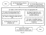
- the method actions in the user equipment 900 for applying power scaling to uplink transmissions in a multiple cell communications network will now be described with reference to a flowchart depicted in Figure 12 .
- the actions do not have to be taken in the order stated below, but may be taken in any suitable order. Actions performed in some embodiments are marked with dashed boxes.
- the user equipment 900 is configured to transmit over a plurality of aggregated cells in uplink to a network node 800.
- the user equipment 900 receives from the network node 800, timing advance information for UL for one or more aggregated cells of the plurality of aggregated cells.
- the user equipment 900 may check whether uplink transmissions over cells exceeds transmit power maximum of the user equipment 900 and in that case apply the power scaling.
- the user equipment 900 applies a power scaling to uplink transmissions of at least one aggregated cell out of the plurality of aggregated cells based on the received timing advance information.
- the at least one aggregated cell is associated with the user equipment 900 and is a cell of the multiple cell communications network.
- the user equipment applies power scaling for a period of a subframe of the at least one aggregated cell, which period is based on the received timing advance information. A length in time of the period of the subframe may be based on the received timing advance information for one or more aggregated cells.
- the user equipment 900 may apply power scaling to uplink transmissions of all aggregated cells, which are associated with the user equipment 900.
- the user equipment 900 applies the power scaling by setting the transmit power of at least one aggregated cell to zero.
- the power scaling may be omitted during uplink transmissions of sounding reference signals.
- the user equipment 900 may, in some embodiments, apply a maximum power per UL cell such that power limitations in transition periods never occur.
- the user equipment 900 may apply the power scaling by designating at least one aggregated cell of the multiple communications cell network as a protected cell and that power scaling is omitted on uplink transmissions of the protected cell.
- the protected cell may be a primary cell and/or at least one secondary cell.
- the protected cell is a cell that comprises a sub-frame that occurs first in time relative to subframes of other aggregated cells.
- the protected cell is a cell that comprises a sub-frame that occurs last in time relative to subframes of other aggregated cells.
- the user equipment 900 may apply the power scaling to a beginning, an end, or the beginning and the end of selected sub-frames of the at least one aggregated cell.
- the user equipment 900 may apply the power scaling to identified regions of sub-frames with power limitations.
- the user equipment 900 may send to the network node 800 one or more uplink transmissions with the applied power scaling.
- some embodiments relate to a method, in a user equipment, for applying power scaling in a multiple cell communications network in presence of multiple uplink timing advancements, each for uplink transmissions in respective cell in the multiple cell communications network.
- the method comprising: receiving (see action 10), from a base station, timing advancement information for the respective cell; and applying (see action 12) a power scaling to uplink transmissions in at least one cell, associated with the user equipment, of the multiple cell communications network based on the received timing advancement information.
- the method of example embodiment 1, wherein the applying the power scaling further comprises applying the power scaling to all aggregated cells which are associated with the user equipment.
- the method of example embodiment 2 wherein the power scaling is applied equally to all aggregated cells.
- applying the power scaling further comprises applying a maximum power per UL cell such that power limitations in transition periods never occur.
- the applying the power scaling further comprises designating at least one aggregated cell of the multiple communications cell network as a protected cell, such that no power scaling is applied to the protected cell.
- the applying the power scaling comprises to apply power scaling at a beginning of a subframe of a first cell until a beginning of a second cell.
- the applying the power scaling may comprise to apply power scaling at an end of a subframe of a first cell until an end of a second cell.
- the applying a power scaling over the whole subframe comprises reducing transmit power of at least one aggregated cell over the whole subframe taking transmit power of the different aggregated cells into account relative a maximum, also called Release-10 scaling.
- the applying the power scaling further comprises applying the power scaling to a beginning, end, and/or beginning and end of selected sub-frames of the at least one aggregated cells.
- Figure 13 is a block diagram depicting a user equipment according to some embodiments herein for applying power scaling to uplink transmissions in a multiple cell communications network.
- the user equipment 900 is configured to transmit over a plurality of aggregated cells in uplink to a network node 800.
- the user equipment 900 comprises a receiver 1301 configured to receive, from the network node 800, timing advance information for UL for one or more aggregated cells of the plurality of aggregated cells.
- the user equipment 900 further comprises an applying circuit 1302 configured to apply a power scaling to uplink transmissions of at least one aggregated cell out of the plurality of aggregated cells based on the received timing advance information.
- the at least one aggregated cell is associated with the user equipment 900 and is a cell of the multiple cell communications network.
- the applying circuit 1302 is configured to apply the power scaling for a period of a subframe of the at least one aggregated cell.
- the period is based on the received timing advance information.
- a length in time of the period of the subframe may be based on the received timing advance information for one or more aggregated cells.
- the applying circuit 1302 is configured to apply power scaling to uplink transmissions of all aggregated cells.
- the aggregated cells are associated with the user equipment 900.
- the applying circuit 1302 may be configured to set the transmit power of at least one aggregated cell to zero.
- the applying circuit 1302 may be configured to omit power scaling during uplink transmissions of sounding reference signals.
- the applying circuit 1302 may be configured to designate at least one aggregated cell of the multiple communications cell network as a protected cell.
- the applying circuit may further be configured to omit power scaling on uplink transmissions of the protected cell.
- the protected cell may be a primary cell and/or at least one secondary cell.
- the protected cell may be a cell that comprises a sub-frame that occurs first in time relative to subframes of other aggregated cells.
- the protected cell may be a cell that comprises a sub-frame that occurs last in time relative to subframes of other aggregated cells.
- the applying circuit 1302 may further be configured to apply the power scaling to a beginning, an end, or the beginning and the end of selected sub-frames of the at least one aggregated cell.
- the applying circuit 1302 may additionally be configured to apply the power scaling to identified regions of sub-frames with power limitations.
- the user equipment 900 may also comprise a checking circuit 1303 configured to check whether uplink transmissions over cells exceeds maximum transmit power of the user equipment 900. In that case, the applying circuit 1302 is configured to perform the power scaling.
- the user equipment 900 further comprises a transmitter 1304 that may be configured to send to the network node 800 one or more uplink transmissions with the applied power scaling.
- the receiver 1301 and the transmitter 1304 may be comprised in a radio circuit 1305 in the user equipment 900.
- the applying circuit 1302 and/or the checking circuit 1303 may be part of a processing circuit 1306.
- the user equipment 900 or wireless device above comprises the processing circuitry 1306, a memory 1307, the radio circuitry 1305, and at least one antenna.
- the radio circuitry 1305 may comprise RF circuitry and baseband processing circuitry (not shown) which may be used to configure the user equipment 900 (UE) according to one or more of the herein disclosed embodiments or embodiments.
- some or all of the functionality described above as being provided by mobile communication devices or other forms of wireless device may be provided by the processing circuitry 1306 executing instructions stored on a computer-readable medium, such as the memory 1307 shown in Figure 13 .
- Alternative embodiments of the user equipment 900 may include additional components beyond those shown in Figure 13 that may be responsible for providing certain aspects of the user equipment's functionality, including any of the functionality described above and/or any functionality necessary to support the embodiment described above.
- the circuitries mentioned above may be used (any of them that is or in any combination) to execute one or more of the earlier mentioned embodiments, embodiment 1-5, and/or embodiments 1-5.
- the circuitries may also perform or include means for executing a embodiment according to the earlier disclosed flowcharts. All these circuitries may be comprised in a UE of an LTE system as earlier mentioned.
- a computer-readable medium may include removable and non-removable storage devices including, but not limited to, Read Only Memory (ROM), Random Access Memory (RAM), compact discs (CDs), digital versatile discs (DVD), etc.
- program modules may include routines, programs, objects, components, data structures, etc. that perform particular tasks or implement particular abstract data types.
- Computer-executable instructions, associated data structures, and program modules represent examples of program code for executing steps of the methods disclosed herein. The particular sequence of such executable instructions or associated data structures represents examples of corresponding acts for implementing the functions described in such steps or processes.
- embodiments herein relate to a user equipment for power scaling in a presence of a multiple UL timing advancement in a multiple cell communications network.
- the user equipment comprises a radio circuitry 1305 configured to receive, from a network node 800, timing advancement information.
- the user equipment further comprises a processing circuitry 1306 configured to apply a power scaling to at least one aggregated cell, associated with the user equipment, of the multiple cell communications network based on the received timing advancement information.
- the user equipment of example embodiment 15, wherein the processing circuitry 1306 is further configured to apply the power scaling to all aggregated cells which are associated with the user equipment.
- the user equipment of example embodiment 16 wherein the power scaling is applied equally to all aggregated cells.
- the user equipment of example embodiment 15, wherein the processing circuitry 1306 is further configured to apply a maximum power per UL cell such that power limitations in transition periods never occur.
- the user equipment of example embodiment 15, wherein the processing circuitry 1306 is further configured to designate at least one aggregated cell of the multiple communications cell network as a protected cell, such that no power scaling is applied to the protected cell.
- the user equipment of example embodiment 19, wherein the protected cell is a primary cell and/or at least one secondary cell.
- the user equipment of any of examples embodiments 19 or 20, wherein the protected cell is a cell which comprises a sub-frame that occurs first in time.
- the user equipment of any of example embodiments 19 or 20, wherein the protected cell is a cell which comprises a sub-frame that occurs last in time.
- the method actions in the network node 800 for demodulating uplink transmissions from the user equipment 900 in a multiple cell communications network will now be described with reference to a flowchart depicted in Figure 14 .
- the steps do not have to be taken in the order stated below, but may be taken in any suitable order.
- the network node is configured to receive over a plurality of aggregated cells uplink transmissions from the user equipment 900.
- the network node 800 transmits, to the user equipment 900, determined timing advance information for UL of one or more aggregated cells of the plurality of aggregated cells.
- the network node 800 receives, from the user equipment 900, an uplink transmission of at least one aggregated cell out of the plurality of aggregated cells.
- the network node 800 may weight soft values resulting in the weighted soft values for the periods.
- the network node 800 may set the soft values to zero. E.g. weight soft values in uncertainty periods in the received uplink transmission based on the transmitted timing advance information.
- the network node 800 may weight by identifying the periods in the received uplink transmission.
- the network node 800 may identify the periods is based on determined timing advance information or detected uplink energy levels. Identify periods of increased power reduction, i.e. scaling, of the uplink transmission or Identify periods of less power reduction, i.e. scaling, in the received uplink transmission.
- the network node 800 may weight by identifying soft values of bits associated with said periods of power scaling with a smaller or larger weighting factors during the demodulating of said received uplink transmission. E.g. provide soft values of bits associated with said periods a greater degree of trustworthiness, weighting soft values with larger numbers.
- the network node 800 may designate soft values of bits associated with said periods with a lower degree of trustworthiness, e.g. weighting with smaller numbers, during a decoding of the received uplink transmission.
- the network node 800 demodulates the received uplink transmission using weighted soft values in periods in the received uplink transmission, which periods are based on the transmitted timing advance information.
- embodiments relate to a method, in a base station, for demodulating uplink transmissions in a presence of multiple UL timing advancement in a multiple cell communications network.
- the method comprising: transmitting, to a user equipment, timing advancement information; receiving, from a user equipment, an uplink transmission; and weighting soft values in uncertainty periods in the received uplink transmission based on the transmitted timing advancement information.
- the weighting further comprises: identifying portions or periods of increased power reduction (scaling) in the received uplink transmission; and designating soft values of bits associated with said portions/periods with a lower degree of trustworthiness (weighting soft values with smaller numbers) during a decoding of said received uplink transmission.
- weighting of soft values further comprises identifying portions/periods of less power reduction (scaling) in the received uplink transmission; and providing soft values of bits associated with said portions/periods of less power scaling a greater degree of trustworthiness, weighting soft values with larger numbers.
- Figure 15 is a block diagram depicting a network node 800 according to some embodiments herein for demodulating uplink transmissions from the user equipment 900 in the multiple cell communications network.
- the network node 800 is configured to receive over a plurality of aggregated cells uplink transmissions from the user equipment 900.
- the network node 800 comprises a transmitter 1501 configured to transmit, to the user equipment 900, determined timing advance information for UL of one or more aggregated cells of the plurality of aggregated cells.
- the network node 800 further comprises a receiver 1502 configured to receive, from the user equipment 900, an uplink transmission of at least one aggregated cell out of the plurality of aggregated cells.
- the network node 800 additionally comprises a demodulating circuit 1503 configured to demodulate the received uplink transmission using weighted soft values in periods in the received uplink transmission. The periods are based on the transmitted timing advance information.
- the network node 800 may in some embodiments further comprise a weighting circuit 1504 configured to weight soft values resulting in the weighted soft values for the periods.
- the weighting circuit 1504 may be configured to set the soft values to zero.
- the weighting circuit 1504 is configured to identify the periods in the received uplink transmission.
- the weighting circuit 1504 is then further configured to provide soft values of bits associated with said periods of power scaling with smaller or larger weighting factors to the demodulating circuit 1503 of said received uplink transmission.
- the weighting circuit 1504 is configured to identify the periods based on determined timing advance information or detected uplink energy levels.
- the network node 800 may comprise a radio circuitry 1505 configured to send, to the user equipment 900, timing advancement information.
- the radio circuitry 1505 may further be configured to receive, from the user equipment 900, an uplink transmission.
- the network node 800 may further comprise a processing circuitry 1506 configured to weight soft values in uncertainty periods in the received uplink transmission based on the transmitted timing advancement information.
- the processing circuitry 1506 is further configured to identify portions of increased power reduction, scaling, in the received uplink transmission.
- the processing circuitry 1506 may further be configured to designate soft values of bits associated with said portions with a lower degree of trustworthiness (weighting soft values with smaller numbers) during a decoding of said received uplink transmission.
- the processing circuitry 1506 may further be configured to identify portions of less power reduction or scaling in the received uplink transmission.
- the processing circuitry 1506 may also be configured to provide soft values of bits associated with said portions of less power scaling a greater degree of trustworthiness, weighting soft values with larger numbers.
- the network node 800 further comprises a memory 1507 that may comprise one or more memory units and may be used to store for example data such as threshold values, quality values, user equipment context, timers, cyphering keys, application to perform the methods herein when being executed on the network node 800 or similar.
- a memory 1507 may comprise one or more memory units and may be used to store for example data such as threshold values, quality values, user equipment context, timers, cyphering keys, application to perform the methods herein when being executed on the network node 800 or similar.
Applications Claiming Priority (2)
| Application Number | Priority Date | Filing Date | Title |
|---|---|---|---|
| US201261591940P | 2012-01-29 | 2012-01-29 | |
| EP12730060.6A EP2807873A1 (fr) | 2012-01-29 | 2012-06-12 | Équipement utilisateur, n ud de réseau et procédé pour l'application d'une adaptation de puissance aux transmissions dans le sens montant |
Related Parent Applications (1)
| Application Number | Title | Priority Date | Filing Date |
|---|---|---|---|
| EP12730060.6A Division EP2807873A1 (fr) | 2012-01-29 | 2012-06-12 | Équipement utilisateur, n ud de réseau et procédé pour l'application d'une adaptation de puissance aux transmissions dans le sens montant |
Publications (2)
| Publication Number | Publication Date |
|---|---|
| EP2903356A1 true EP2903356A1 (fr) | 2015-08-05 |
| EP2903356B1 EP2903356B1 (fr) | 2018-02-28 |
Family
ID=46384451
Family Applications (2)
| Application Number | Title | Priority Date | Filing Date |
|---|---|---|---|
| EP15153819.6A Active EP2903356B1 (fr) | 2012-01-29 | 2012-06-12 | Noeud de réseau et procédés associés |
| EP12730060.6A Withdrawn EP2807873A1 (fr) | 2012-01-29 | 2012-06-12 | Équipement utilisateur, n ud de réseau et procédé pour l'application d'une adaptation de puissance aux transmissions dans le sens montant |
Family Applications After (1)
| Application Number | Title | Priority Date | Filing Date |
|---|---|---|---|
| EP12730060.6A Withdrawn EP2807873A1 (fr) | 2012-01-29 | 2012-06-12 | Équipement utilisateur, n ud de réseau et procédé pour l'application d'une adaptation de puissance aux transmissions dans le sens montant |
Country Status (9)
| Country | Link |
|---|---|
| EP (2) | EP2903356B1 (fr) |
| CN (1) | CN104081836B (fr) |
| AR (1) | AR089819A1 (fr) |
| AU (1) | AU2012367384C1 (fr) |
| BR (1) | BR112014018631A8 (fr) |
| CA (1) | CA2862197A1 (fr) |
| IN (1) | IN2014KN01525A (fr) |
| WO (1) | WO2013112089A1 (fr) |
| ZA (1) | ZA201404628B (fr) |
Families Citing this family (4)
| Publication number | Priority date | Publication date | Assignee | Title |
|---|---|---|---|---|
| CN104427604B (zh) * | 2013-08-28 | 2018-10-12 | 上海诺基亚贝尔股份有限公司 | 一种用于分配上行功率的方法和设备 |
| US11240774B2 (en) * | 2017-06-02 | 2022-02-01 | Qualcomm Incorporated | Timing advance group for new radio |
| CN112005575B (zh) * | 2018-04-18 | 2024-03-19 | 株式会社Ntt都科摩 | 用户终端以及无线通信方法 |
| WO2021147094A1 (fr) * | 2020-01-23 | 2021-07-29 | Qualcomm Incorporated | Limitation de temps sur la transmission de liaison montante sur différentes cellules |
Citations (4)
| Publication number | Priority date | Publication date | Assignee | Title |
|---|---|---|---|---|
| EP1096718A2 (fr) * | 1999-10-28 | 2001-05-02 | Lucent Technologies Inc. | Transmission de données à diversité, qui emploie plusieurs types de modulation |
| WO2011098186A1 (fr) * | 2010-02-15 | 2011-08-18 | Telefonaktiebolaget L M Ericsson (Publ) | Procédés et agencements dans des systèmes de communication radio |
| WO2011120716A1 (fr) * | 2010-04-01 | 2011-10-06 | Panasonic Corporation | Commande de puissance de transmission pour des canaux d'accès aléatoire physiques |
| WO2011129716A1 (fr) | 2010-04-13 | 2011-10-20 | Общество С Ограниченной Ответственностью "Гaмabeтфapм" | Moyen pour la prévention et le traitement de pancréatite aiguë et chronique |
Family Cites Families (8)
| Publication number | Priority date | Publication date | Assignee | Title |
|---|---|---|---|---|
| US8169953B2 (en) * | 2005-05-17 | 2012-05-01 | Qualcomm Incorporated | Method and apparatus for wireless multi-carrier communications |
| CN101646234A (zh) * | 2009-09-01 | 2010-02-10 | 中兴通讯股份有限公司 | 一种定时提前量的获取方法 |
| CN101674642B (zh) * | 2009-09-29 | 2014-04-30 | 中兴通讯股份有限公司 | 一种多天线终端发射功率的控制方法和系统 |
| CN102065535B (zh) * | 2009-11-11 | 2014-07-23 | 电信科学技术研究院 | 一种随机接入过程中定时提前量的确定方法及装置 |
| EP2360866A1 (fr) * | 2010-02-12 | 2011-08-24 | Panasonic Corporation | Activation et désactivation des composantes de fréquences en fonction d'allocation de ressources |
| US9363769B2 (en) * | 2010-05-05 | 2016-06-07 | Qualcomm Incorporated | Methods and systems for SRS power scaling in carrier aggregation |
| WO2013006111A1 (fr) * | 2011-07-06 | 2013-01-10 | Telefonaktiebolaget L M Ericsson (Publ) | Accès aléatoire utilisant des communications par porteuses élémentaires primaire et secondaire |
| US9204411B2 (en) * | 2011-09-12 | 2015-12-01 | Qualcomm Incorporated | Support of multiple timing advance groups for user equipment in carrier aggregation in LTE |
-
2012
- 2012-06-12 AU AU2012367384A patent/AU2012367384C1/en not_active Ceased
- 2012-06-12 IN IN1525KON2014 patent/IN2014KN01525A/en unknown
- 2012-06-12 BR BR112014018631A patent/BR112014018631A8/pt not_active IP Right Cessation
- 2012-06-12 CN CN201280068330.3A patent/CN104081836B/zh active Active
- 2012-06-12 WO PCT/SE2012/050629 patent/WO2013112089A1/fr active Application Filing
- 2012-06-12 EP EP15153819.6A patent/EP2903356B1/fr active Active
- 2012-06-12 CA CA2862197A patent/CA2862197A1/fr not_active Abandoned
- 2012-06-12 EP EP12730060.6A patent/EP2807873A1/fr not_active Withdrawn
-
2013
- 2013-01-25 AR ARP130100242A patent/AR089819A1/es not_active Application Discontinuation
-
2014
- 2014-06-24 ZA ZA2014/04628A patent/ZA201404628B/en unknown
Patent Citations (4)
| Publication number | Priority date | Publication date | Assignee | Title |
|---|---|---|---|---|
| EP1096718A2 (fr) * | 1999-10-28 | 2001-05-02 | Lucent Technologies Inc. | Transmission de données à diversité, qui emploie plusieurs types de modulation |
| WO2011098186A1 (fr) * | 2010-02-15 | 2011-08-18 | Telefonaktiebolaget L M Ericsson (Publ) | Procédés et agencements dans des systèmes de communication radio |
| WO2011120716A1 (fr) * | 2010-04-01 | 2011-10-06 | Panasonic Corporation | Commande de puissance de transmission pour des canaux d'accès aléatoire physiques |
| WO2011129716A1 (fr) | 2010-04-13 | 2011-10-20 | Общество С Ограниченной Ответственностью "Гaмabeтфapм" | Moyen pour la prévention et le traitement de pancréatite aiguë et chronique |
Also Published As
| Publication number | Publication date |
|---|---|
| EP2903356B1 (fr) | 2018-02-28 |
| CA2862197A1 (fr) | 2013-08-01 |
| AU2012367384B2 (en) | 2015-09-24 |
| ZA201404628B (en) | 2016-07-27 |
| BR112014018631A8 (pt) | 2017-07-11 |
| AR089819A1 (es) | 2014-09-17 |
| CN104081836A (zh) | 2014-10-01 |
| WO2013112089A1 (fr) | 2013-08-01 |
| AU2012367384A1 (en) | 2014-08-14 |
| IN2014KN01525A (fr) | 2015-10-23 |
| CN104081836B (zh) | 2018-07-06 |
| AU2012367384C1 (en) | 2016-01-21 |
| BR112014018631A2 (fr) | 2017-06-20 |
| EP2807873A1 (fr) | 2014-12-03 |
Similar Documents
| Publication | Publication Date | Title |
|---|---|---|
| US20150071236A1 (en) | User Equipment, Network Node and Methods Therein | |
| US10721704B2 (en) | Network node, user equipment and methods therein for adjusting the transmit timing of uplink transmissions | |
| US20190230633A1 (en) | Sidelink signal transmission/reception method of ue in wireless communication system | |
| EP2385652A1 (fr) | Procédé d'amélioration de transmission de liaison montante et dispositif de communication associé | |
| KR20120124442A (ko) | 무선 통신 시스템, 이동국 장치, 무선 통신 방법 및 집적 회로 | |
| EP3536050B1 (fr) | Masque temporel marche/arrêt pour tti court | |
| KR20130001096A (ko) | 무선 통신 시스템에서 랜덤 액세스의 수행장치 및 방법 | |
| WO2011042336A2 (fr) | Procédés et agencements dans un réseau de télécommunication mobile | |
| EP3611856B1 (fr) | Procédé et appareil de transmission d'un signal de liaison latérale dans un système de communication sans fil | |
| CN107005989B (zh) | 终端设备、网络设备、上行参考信号发送方法和接收方法 | |
| US20180234965A1 (en) | Method and apparatus for transmitting data in unlicensed band | |
| US10306649B2 (en) | Methods for identifying mobile stations that are near neighbor cells | |
| EP2903356B1 (fr) | Noeud de réseau et procédés associés | |
| WO2018236276A1 (fr) | Adaptation de masque marche/arrêt pour nr avec différentes numérologies | |
| EP3454488B1 (fr) | Procédé et dispositif pour surveiller un canal de commande | |
| US20180310210A1 (en) | Method and apparatus for supporting fast handover in wireless communication system | |
| US20200037261A1 (en) | Uplink transmission power control method and device using same |
Legal Events
| Date | Code | Title | Description |
|---|---|---|---|
| PUAI | Public reference made under article 153(3) epc to a published international application that has entered the european phase |
Free format text: ORIGINAL CODE: 0009012 |
|
| 17P | Request for examination filed |
Effective date: 20150204 |
|
| AC | Divisional application: reference to earlier application |
Ref document number: 2807873 Country of ref document: EP Kind code of ref document: P |
|
| AK | Designated contracting states |
Kind code of ref document: A1 Designated state(s): AL AT BE BG CH CY CZ DE DK EE ES FI FR GB GR HR HU IE IS IT LI LT LU LV MC MK MT NL NO PL PT RO RS SE SI SK SM TR |
|
| REG | Reference to a national code |
Ref country code: DE Ref legal event code: R079 Ref document number: 602012043556 Country of ref document: DE Free format text: PREVIOUS MAIN CLASS: H04W0052340000 Ipc: H04W0052280000 |
|
| GRAP | Despatch of communication of intention to grant a patent |
Free format text: ORIGINAL CODE: EPIDOSNIGR1 |
|
| RIC1 | Information provided on ipc code assigned before grant |
Ipc: H04W 56/00 20090101ALI20171116BHEP Ipc: H04W 52/28 20090101AFI20171116BHEP Ipc: H04W 52/34 20090101ALI20171116BHEP Ipc: H04L 25/03 20060101ALI20171116BHEP Ipc: H04W 52/14 20090101ALI20171116BHEP Ipc: H04L 5/00 20060101ALI20171116BHEP |
|
| INTG | Intention to grant announced |
Effective date: 20171211 |
|
| GRAS | Grant fee paid |
Free format text: ORIGINAL CODE: EPIDOSNIGR3 |
|
| GRAA | (expected) grant |
Free format text: ORIGINAL CODE: 0009210 |
|
| AC | Divisional application: reference to earlier application |
Ref document number: 2807873 Country of ref document: EP Kind code of ref document: P |
|
| AK | Designated contracting states |
Kind code of ref document: B1 Designated state(s): AL AT BE BG CH CY CZ DE DK EE ES FI FR GB GR HR HU IE IS IT LI LT LU LV MC MK MT NL NO PL PT RO RS SE SI SK SM TR |
|
| REG | Reference to a national code |
Ref country code: GB Ref legal event code: FG4D Ref country code: CH Ref legal event code: EP |
|
| REG | Reference to a national code |
Ref country code: AT Ref legal event code: REF Ref document number: 975446 Country of ref document: AT Kind code of ref document: T Effective date: 20180315 |
|
| REG | Reference to a national code |
Ref country code: IE Ref legal event code: FG4D |
|
| REG | Reference to a national code |
Ref country code: DE Ref legal event code: R096 Ref document number: 602012043556 Country of ref document: DE |
|
| REG | Reference to a national code |
Ref country code: NL Ref legal event code: FP |
|
| REG | Reference to a national code |
Ref country code: LT Ref legal event code: MG4D |
|
| REG | Reference to a national code |
Ref country code: AT Ref legal event code: MK05 Ref document number: 975446 Country of ref document: AT Kind code of ref document: T Effective date: 20180228 |
|
| PG25 | Lapsed in a contracting state [announced via postgrant information from national office to epo] |
Ref country code: FI Free format text: LAPSE BECAUSE OF FAILURE TO SUBMIT A TRANSLATION OF THE DESCRIPTION OR TO PAY THE FEE WITHIN THE PRESCRIBED TIME-LIMIT Effective date: 20180228 Ref country code: CY Free format text: LAPSE BECAUSE OF FAILURE TO SUBMIT A TRANSLATION OF THE DESCRIPTION OR TO PAY THE FEE WITHIN THE PRESCRIBED TIME-LIMIT Effective date: 20180228 Ref country code: HR Free format text: LAPSE BECAUSE OF FAILURE TO SUBMIT A TRANSLATION OF THE DESCRIPTION OR TO PAY THE FEE WITHIN THE PRESCRIBED TIME-LIMIT Effective date: 20180228 Ref country code: NO Free format text: LAPSE BECAUSE OF FAILURE TO SUBMIT A TRANSLATION OF THE DESCRIPTION OR TO PAY THE FEE WITHIN THE PRESCRIBED TIME-LIMIT Effective date: 20180528 Ref country code: ES Free format text: LAPSE BECAUSE OF FAILURE TO SUBMIT A TRANSLATION OF THE DESCRIPTION OR TO PAY THE FEE WITHIN THE PRESCRIBED TIME-LIMIT Effective date: 20180228 Ref country code: LT Free format text: LAPSE BECAUSE OF FAILURE TO SUBMIT A TRANSLATION OF THE DESCRIPTION OR TO PAY THE FEE WITHIN THE PRESCRIBED TIME-LIMIT Effective date: 20180228 |
|
| PG25 | Lapsed in a contracting state [announced via postgrant information from national office to epo] |
Ref country code: GR Free format text: LAPSE BECAUSE OF FAILURE TO SUBMIT A TRANSLATION OF THE DESCRIPTION OR TO PAY THE FEE WITHIN THE PRESCRIBED TIME-LIMIT Effective date: 20180529 Ref country code: BG Free format text: LAPSE BECAUSE OF FAILURE TO SUBMIT A TRANSLATION OF THE DESCRIPTION OR TO PAY THE FEE WITHIN THE PRESCRIBED TIME-LIMIT Effective date: 20180528 Ref country code: RS Free format text: LAPSE BECAUSE OF FAILURE TO SUBMIT A TRANSLATION OF THE DESCRIPTION OR TO PAY THE FEE WITHIN THE PRESCRIBED TIME-LIMIT Effective date: 20180228 Ref country code: AT Free format text: LAPSE BECAUSE OF FAILURE TO SUBMIT A TRANSLATION OF THE DESCRIPTION OR TO PAY THE FEE WITHIN THE PRESCRIBED TIME-LIMIT Effective date: 20180228 Ref country code: SE Free format text: LAPSE BECAUSE OF FAILURE TO SUBMIT A TRANSLATION OF THE DESCRIPTION OR TO PAY THE FEE WITHIN THE PRESCRIBED TIME-LIMIT Effective date: 20180228 Ref country code: LV Free format text: LAPSE BECAUSE OF FAILURE TO SUBMIT A TRANSLATION OF THE DESCRIPTION OR TO PAY THE FEE WITHIN THE PRESCRIBED TIME-LIMIT Effective date: 20180228 |
|
| PG25 | Lapsed in a contracting state [announced via postgrant information from national office to epo] |
Ref country code: RO Free format text: LAPSE BECAUSE OF FAILURE TO SUBMIT A TRANSLATION OF THE DESCRIPTION OR TO PAY THE FEE WITHIN THE PRESCRIBED TIME-LIMIT Effective date: 20180228 Ref country code: IT Free format text: LAPSE BECAUSE OF FAILURE TO SUBMIT A TRANSLATION OF THE DESCRIPTION OR TO PAY THE FEE WITHIN THE PRESCRIBED TIME-LIMIT Effective date: 20180228 Ref country code: EE Free format text: LAPSE BECAUSE OF FAILURE TO SUBMIT A TRANSLATION OF THE DESCRIPTION OR TO PAY THE FEE WITHIN THE PRESCRIBED TIME-LIMIT Effective date: 20180228 Ref country code: AL Free format text: LAPSE BECAUSE OF FAILURE TO SUBMIT A TRANSLATION OF THE DESCRIPTION OR TO PAY THE FEE WITHIN THE PRESCRIBED TIME-LIMIT Effective date: 20180228 Ref country code: PL Free format text: LAPSE BECAUSE OF FAILURE TO SUBMIT A TRANSLATION OF THE DESCRIPTION OR TO PAY THE FEE WITHIN THE PRESCRIBED TIME-LIMIT Effective date: 20180228 |
|
| REG | Reference to a national code |
Ref country code: DE Ref legal event code: R097 Ref document number: 602012043556 Country of ref document: DE |
|
| PG25 | Lapsed in a contracting state [announced via postgrant information from national office to epo] |
Ref country code: DK Free format text: LAPSE BECAUSE OF FAILURE TO SUBMIT A TRANSLATION OF THE DESCRIPTION OR TO PAY THE FEE WITHIN THE PRESCRIBED TIME-LIMIT Effective date: 20180228 Ref country code: SK Free format text: LAPSE BECAUSE OF FAILURE TO SUBMIT A TRANSLATION OF THE DESCRIPTION OR TO PAY THE FEE WITHIN THE PRESCRIBED TIME-LIMIT Effective date: 20180228 Ref country code: SM Free format text: LAPSE BECAUSE OF FAILURE TO SUBMIT A TRANSLATION OF THE DESCRIPTION OR TO PAY THE FEE WITHIN THE PRESCRIBED TIME-LIMIT Effective date: 20180228 Ref country code: CZ Free format text: LAPSE BECAUSE OF FAILURE TO SUBMIT A TRANSLATION OF THE DESCRIPTION OR TO PAY THE FEE WITHIN THE PRESCRIBED TIME-LIMIT Effective date: 20180228 |
|
| PLBE | No opposition filed within time limit |
Free format text: ORIGINAL CODE: 0009261 |
|
| STAA | Information on the status of an ep patent application or granted ep patent |
Free format text: STATUS: NO OPPOSITION FILED WITHIN TIME LIMIT |
|
| REG | Reference to a national code |
Ref country code: CH Ref legal event code: PL |
|
| 26N | No opposition filed |
Effective date: 20181129 |
|
| PG25 | Lapsed in a contracting state [announced via postgrant information from national office to epo] |
Ref country code: SI Free format text: LAPSE BECAUSE OF FAILURE TO SUBMIT A TRANSLATION OF THE DESCRIPTION OR TO PAY THE FEE WITHIN THE PRESCRIBED TIME-LIMIT Effective date: 20180228 |
|
| REG | Reference to a national code |
Ref country code: BE Ref legal event code: MM Effective date: 20180630 |
|
| REG | Reference to a national code |
Ref country code: IE Ref legal event code: MM4A |
|
| PG25 | Lapsed in a contracting state [announced via postgrant information from national office to epo] |
Ref country code: LU Free format text: LAPSE BECAUSE OF NON-PAYMENT OF DUE FEES Effective date: 20180612 Ref country code: MC Free format text: LAPSE BECAUSE OF FAILURE TO SUBMIT A TRANSLATION OF THE DESCRIPTION OR TO PAY THE FEE WITHIN THE PRESCRIBED TIME-LIMIT Effective date: 20180228 |
|
| PG25 | Lapsed in a contracting state [announced via postgrant information from national office to epo] |
Ref country code: FR Free format text: LAPSE BECAUSE OF NON-PAYMENT OF DUE FEES Effective date: 20180630 Ref country code: LI Free format text: LAPSE BECAUSE OF NON-PAYMENT OF DUE FEES Effective date: 20180630 Ref country code: CH Free format text: LAPSE BECAUSE OF NON-PAYMENT OF DUE FEES Effective date: 20180630 Ref country code: IE Free format text: LAPSE BECAUSE OF NON-PAYMENT OF DUE FEES Effective date: 20180612 |
|
| PG25 | Lapsed in a contracting state [announced via postgrant information from national office to epo] |
Ref country code: BE Free format text: LAPSE BECAUSE OF NON-PAYMENT OF DUE FEES Effective date: 20180630 |
|
| PG25 | Lapsed in a contracting state [announced via postgrant information from national office to epo] |
Ref country code: MT Free format text: LAPSE BECAUSE OF NON-PAYMENT OF DUE FEES Effective date: 20180612 |
|
| PG25 | Lapsed in a contracting state [announced via postgrant information from national office to epo] |
Ref country code: TR Free format text: LAPSE BECAUSE OF FAILURE TO SUBMIT A TRANSLATION OF THE DESCRIPTION OR TO PAY THE FEE WITHIN THE PRESCRIBED TIME-LIMIT Effective date: 20180228 |
|
| PG25 | Lapsed in a contracting state [announced via postgrant information from national office to epo] |
Ref country code: PT Free format text: LAPSE BECAUSE OF FAILURE TO SUBMIT A TRANSLATION OF THE DESCRIPTION OR TO PAY THE FEE WITHIN THE PRESCRIBED TIME-LIMIT Effective date: 20180228 |
|
| PG25 | Lapsed in a contracting state [announced via postgrant information from national office to epo] |
Ref country code: HU Free format text: LAPSE BECAUSE OF FAILURE TO SUBMIT A TRANSLATION OF THE DESCRIPTION OR TO PAY THE FEE WITHIN THE PRESCRIBED TIME-LIMIT; INVALID AB INITIO Effective date: 20120612 Ref country code: MK Free format text: LAPSE BECAUSE OF NON-PAYMENT OF DUE FEES Effective date: 20180228 |
|
| PG25 | Lapsed in a contracting state [announced via postgrant information from national office to epo] |
Ref country code: IS Free format text: LAPSE BECAUSE OF FAILURE TO SUBMIT A TRANSLATION OF THE DESCRIPTION OR TO PAY THE FEE WITHIN THE PRESCRIBED TIME-LIMIT Effective date: 20180628 |
|
| PGFP | Annual fee paid to national office [announced via postgrant information from national office to epo] |
Ref country code: NL Payment date: 20220626 Year of fee payment: 11 |
|
| PGFP | Annual fee paid to national office [announced via postgrant information from national office to epo] |
Ref country code: DE Payment date: 20220629 Year of fee payment: 11 |
|
| PGFP | Annual fee paid to national office [announced via postgrant information from national office to epo] |
Ref country code: GB Payment date: 20230627 Year of fee payment: 12 |
|
| REG | Reference to a national code |
Ref country code: DE Ref legal event code: R119 Ref document number: 602012043556 Country of ref document: DE |
|
| REG | Reference to a national code |
Ref country code: NL Ref legal event code: MM Effective date: 20230701 |
|
| PG25 | Lapsed in a contracting state [announced via postgrant information from national office to epo] |
Ref country code: NL Free format text: LAPSE BECAUSE OF NON-PAYMENT OF DUE FEES Effective date: 20230701 |
|
| PG25 | Lapsed in a contracting state [announced via postgrant information from national office to epo] |
Ref country code: DE Free format text: LAPSE BECAUSE OF NON-PAYMENT OF DUE FEES Effective date: 20240103 |