EP2903306A1 - System and method for mitigating unintended operation - Google Patents
System and method for mitigating unintended operation Download PDFInfo
- Publication number
- EP2903306A1 EP2903306A1 EP15153077.1A EP15153077A EP2903306A1 EP 2903306 A1 EP2903306 A1 EP 2903306A1 EP 15153077 A EP15153077 A EP 15153077A EP 2903306 A1 EP2903306 A1 EP 2903306A1
- Authority
- EP
- European Patent Office
- Prior art keywords
- controls
- signals
- unintended operation
- vehicle
- vehicle controls
- Prior art date
- Legal status (The legal status is an assumption and is not a legal conclusion. Google has not performed a legal analysis and makes no representation as to the accuracy of the status listed.)
- Granted
Links
- 230000000116 mitigating effect Effects 0.000 title claims abstract description 38
- 238000000034 method Methods 0.000 title claims abstract description 30
- 230000004044 response Effects 0.000 claims abstract description 27
- 230000006870 function Effects 0.000 claims description 25
- 230000015654 memory Effects 0.000 claims description 20
- 238000001816 cooling Methods 0.000 claims description 2
- 238000010438 heat treatment Methods 0.000 claims description 2
- 238000009423 ventilation Methods 0.000 claims description 2
- 230000004048 modification Effects 0.000 claims 1
- 238000012986 modification Methods 0.000 claims 1
- 238000012545 processing Methods 0.000 description 7
- 230000004913 activation Effects 0.000 description 4
- 230000033001 locomotion Effects 0.000 description 2
- 230000001133 acceleration Effects 0.000 description 1
- 230000009471 action Effects 0.000 description 1
- 230000003213 activating effect Effects 0.000 description 1
- 238000013459 approach Methods 0.000 description 1
- 230000005540 biological transmission Effects 0.000 description 1
- 230000008859 change Effects 0.000 description 1
- 238000012790 confirmation Methods 0.000 description 1
- 238000013500 data storage Methods 0.000 description 1
- 230000009849 deactivation Effects 0.000 description 1
- 238000010586 diagram Methods 0.000 description 1
- 238000007726 management method Methods 0.000 description 1
- 238000011093 media selection Methods 0.000 description 1
- 230000003287 optical effect Effects 0.000 description 1
- 230000008569 process Effects 0.000 description 1
- 238000012546 transfer Methods 0.000 description 1
- 230000001052 transient effect Effects 0.000 description 1
Images


Classifications
-
- H04W4/046—
-
- B—PERFORMING OPERATIONS; TRANSPORTING
- B60—VEHICLES IN GENERAL
- B60W—CONJOINT CONTROL OF VEHICLE SUB-UNITS OF DIFFERENT TYPE OR DIFFERENT FUNCTION; CONTROL SYSTEMS SPECIALLY ADAPTED FOR HYBRID VEHICLES; ROAD VEHICLE DRIVE CONTROL SYSTEMS FOR PURPOSES NOT RELATED TO THE CONTROL OF A PARTICULAR SUB-UNIT
- B60W50/00—Details of control systems for road vehicle drive control not related to the control of a particular sub-unit, e.g. process diagnostic or vehicle driver interfaces
- B60W50/08—Interaction between the driver and the control system
- B60W50/087—Interaction between the driver and the control system where the control system corrects or modifies a request from the driver
-
- B—PERFORMING OPERATIONS; TRANSPORTING
- B60—VEHICLES IN GENERAL
- B60W—CONJOINT CONTROL OF VEHICLE SUB-UNITS OF DIFFERENT TYPE OR DIFFERENT FUNCTION; CONTROL SYSTEMS SPECIALLY ADAPTED FOR HYBRID VEHICLES; ROAD VEHICLE DRIVE CONTROL SYSTEMS FOR PURPOSES NOT RELATED TO THE CONTROL OF A PARTICULAR SUB-UNIT
- B60W50/00—Details of control systems for road vehicle drive control not related to the control of a particular sub-unit, e.g. process diagnostic or vehicle driver interfaces
- B60W50/0098—Details of control systems ensuring comfort, safety or stability not otherwise provided for
-
- H—ELECTRICITY
- H04—ELECTRIC COMMUNICATION TECHNIQUE
- H04W—WIRELESS COMMUNICATION NETWORKS
- H04W4/00—Services specially adapted for wireless communication networks; Facilities therefor
- H04W4/30—Services specially adapted for particular environments, situations or purposes
- H04W4/40—Services specially adapted for particular environments, situations or purposes for vehicles, e.g. vehicle-to-pedestrians [V2P]
- H04W4/48—Services specially adapted for particular environments, situations or purposes for vehicles, e.g. vehicle-to-pedestrians [V2P] for in-vehicle communication
Definitions
- the present disclosure relates to the field of in-vehicle controls.
- a system and method for mitigating the unintended operation of in-vehicle controls are known in the art.
- vehicle-operator interfaces that include one or more controls to be operated by the operator or occupants of the vehicle.
- the controls may, for example, take the form of buttons, levers, knobs, touch-sensitive surfaces and other similar control types.
- controls may be unintentionally actuated or operated by the driver or occupants of the vehicle.
- a driver may unintentionally operate a steering wheel mounted control (e.g. hands-free call termination, audio volume up or down, cruise control set) as a result of hand-over-hand movement when making a tight turn.
- the unintended operation of the controls may result in driver frustration, driver distraction or unsafe vehicle operation.
- a system and method for mitigating unintended operation of in-vehicle controls is described herein.
- the system and method analyze data and/or signals received from sensors to determine when the vehicle is experiencing changes in the vehicle's direction, dynamic state and/or status.
- the analysis may be applied to data and/or signals from one or more sensors alone or in combination.
- Analysis of the data and/or signals may determine that one or more criterion are met and therefore the vehicle may be an identified state.
- the system and method may disable, deaden or otherwise modify the response to one or more controls in order to mitigate unintended operation.
- vehicle-operator interfaces that include one or more controls intended to be actuated by the operator or occupants of the vehicle.
- vehicle types may include automobiles, trucks, buses, motorcycles, snowmobile, watercraft, aircraft, and other similar vehicles that transport an operator and/or occupants.
- the controls may, for example, take the form of buttons, levers, knobs, touch-sensitive surfaces and other similar control types.
- the controls may operate various functions such as audio volume setting, media selection, playback mode, channel selection, cruise control activation/deactivation, cruise speed setting, hands-free call management, transmission gear selection, navigation system settings, climate control settings and other similar functions available for operation by the operator and/or occupants of the vehicle.
- Unintended operation of a control may include inadvertent operation or misoperation. Misoperation may include intend actuation of the control with unexpected or unintended results.
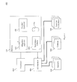
- FIG. 1 is a schematic representation of a system for mitigating unintended operation of in-vehicle controls.
- the system 100 may include a mitigation logic unit 102, one or more sensors 104, one or more controls 106 and one or more function controllers 108.
- Each of the one or more controls 106 may be associated with one or more of the function controllers 108 and each of the one or more function controllers 108 may be associated with one or more of the controls 106.
- the sensors 104 provide input data and/or signals to the mitigation logic unit 102.
- the one or more sensors 104 may include sensors such as, for example, a steering wheel position sensor, an accelerometer (including a multi-axis accelerometer), yaw sensor, pitch sensor, roll sensor, inclination sensor, braking indicator, speedometer, skid detector, airbag deployment indicator and other similar vehicle sensors.
- the data and/or signals received by the mitigation logic unit 102 may be used alone or in combination to determine or infer changes in the vehicle's direction, dynamic state, and/or status.
- the data and/or signals received by the mitigation logic unit 102 may be stored including being stored as an historical sequence of data and/or signal values.
- Changes in the vehicle's direction, dynamic state, and/or status such as turning, accelerating, braking or skidding may contribute to unintended operation of the controls 106 by the operator and/or the occupants. Changes in the vehicle's attitude or direction may cause the operator or occupants to be thrown forward, back or sideways making it difficult to operate controls 106 properly or causing inadvertent contact with one or more control 106.
- FIG. 2 is a schematic representation of example controls in an automobile.
- Example controls (collectively 106) in an automobile cabin may include steering-wheel mounted buttons 106A, steering column stalks 106B, a gear shift lever 106C, dashboard mounted knobs 106D and buttons 106E, and a touch display interface 106F.
- These controls 106 may provide input data and/or signals to function controllers 108 for functions such as turn signals (aka direction indicators), wiper/washer system, audio/infotainment system, hands-free telephony, cruise control, drivetrain/gear selection, heating ventilation and cooling (HVAC), navigation and other similar vehicle functions.
- These example controls 106 are illustrative in nature and are not intended to be limiting in any way.
- the mitigation logic unit 102 may analyze the data and/or signals received from the sensors 104 to determine when the vehicle is experiencing changes the in the vehicle's direction, dynamic state and/or status.
- the data and/or signals analyzed may be current value, historical values or combinations of both.
- the data and/or signal may be retrieved from a storage media 110.
- the storage media 110 may be integral to the mitigation logic unit 102, may be separate from the mitigation logic unit 102 or may be a combination of partially integral and partially separate.
- the analysis may be applied to data and/or signals from any of one or more sensors 104 alone or in combination. Analysis of the data and/or signals may determine that one or more criterion are met and therefore the vehicle may be in an identified state.
- the system 100 may disable, deaden or otherwise modify the response to one or more controls 106.
- the analysis determines that one or more of the criterion are no longer met, the identified state may be abated and the response to the one or more controls 106 may be restored to normal operation.
- the one or more criterion (criteria) used in the analysis may include for example a steering-wheel angle exceeding a threshold (e.g. a tight turn) or the steering-wheel angle in combination with a vehicle speed (e.g. a speed-relative tight turn).
- Other example criteria may include yaw, pitch or roll indicators exceeding a threshold or a rate of change of any of these exceeding a threshold (e.g. vehicle skid or roll-over occurring or imminent).
- Further example criteria may include an incoming call indication, navigation system instructional prompt indication, rough road surface detected, braking exceeding a threshold, acceleration exceeding a threshold and other similar criteria.
- the one or more criterion may be used to determine the on-set, and abatement, of one or more identifiable states.
- the identified states are typically, but not limited to, transient (e.g. having short time duration) in nature.
- the mitigation logic unit 102 may have pre-determined, pre-programmed or user configurable response templates that include the criteria used to determine when an identified state occurs and what control interventions to take when the identified state occurs.
- the interventions may include disabling, deadening or otherwise modifying the response to one or more controls 106.
- the interventions may, for example, include disabling activation or changes in the operation of the windshield wipers, disabling activation or changes in the operation of the cruise control system, disabling inputs to the infotainment unit (e.g. volume, channel or track selection), disabling activation or changes in the operation of the hands free telephony system.
- the interventions may include deadening the response of a control by, for example, requiring a longer time duration operation (e.g.
- the intervention may include modifying the response to a control by, for example, requiring a further confirmation action after an initial control operation in order to activate a corresponding function.
- the intervention may include modifying the response to a control by, for example, disabling or modifying one or more modes available for activating a multi-modal controlled function. For example, a navigation function that normally accepts control inputs in multiple modes, such as touch-screen presses and voice commands, may only accept voice commands (but not touch-screen presses) when an identified state such as the vehicle swerving is occurring.
- the example interventions described therein are illustrative in nature and are not intended to be limiting in any way.
- the interventions made by the mitigation logic unit 102 may be carried out by the mitigation logic unit modifying or cancelling an input from a control 106 before it reaches a corresponding function controller 108, by providing additional input to the function controller 108 to cause it to modify its response to the input received from the control 106, or by a combination of these two approaches.
- the mitigation logic unit 102 may intervene to concurrently modify the response provided by one or more function controllers 108 to inputs received from one or more controls 106.
- Figure 3 is a representation of a method for mitigating unintended operation of in-vehicle controls.
- the method 300 may be, for example, implemented using either of the systems 100 and 400 described herein with reference to Figures 1 and 4 .
- the method 300 may include the following acts.
- the association of interventions for one or more controls 106 with each of one or more identified states may be pre-determined, pre-programmed or user configurable.
- associating interventions with an identified state nay include the criteria used to determine when an identified state occurs. Either or both of the interventions and criteria associated with an identified state may be included in one or more response templates.
- the one or more sensors and the data and/or signals received from the sensors may include any of those described above with reference to Figures 1 and 2 .
- Analyzing the received data and/or signals 306. Analyzing the received data and/or signals may include applying criteria as described above with reference to Figure 1 . Determining when an identified state is occurring 308. An identified state may be determined to occur when one or more thresholds are exceeded and/or one or more indications are received as described above with reference to Figure 1 . Modify response of one or more controls 310. The response of the one or more controls may be modified as described above with reference to Figures 1 and 2 . Determining abatement of identified state 312. The identified state may be determined to be in abatement (e.g.
- Restoring the control responses may include returning the responses to the state they had before they were modified in act 310.
- restoring the control responses may include putting the control responses in a state they would otherwise have had were they not modified in act 310.
- FIG. 4 is a further schematic representation of a system for mitigating unintended operation of in-vehicle controls.
- the system 400 comprises a processor 402, memory 404 (the contents of which are accessible by the processor 402) and an I/O interface 406.
- the memory 404 may store instructions which when executed using the process 402 may cause the system 400 to render the functionality associated with the mitigation logic unit 102 and one or more function controllers 108 as described herein.
- the memory 404 may store data and/or signals 110 received from one or more controls 106 and criteria associated with one or more identified states, including response templates, as described herein 408.
- the processor 402 may comprise a single processor or multiple processors that may be disposed on a single chip, on multiple devices or distributed over more than one system.
- the processor 402 may be hardware that executes computer executable instructions or computer code embodied in the memory 404 or in other memory to perform one or more features of the system.
- the processor 402 may include a general purpose processor, a central processing unit (CPU), a graphics processing unit (GPU), an application specific integrated circuit (ASIC), a digital signal processor (DSP), a field programmable gate array (FPGA), a digital circuit, an analog circuit, a microcontroller, any other type of processor, or any combination thereof.
- the memory 404 may comprise a device for storing and retrieving data, processor executable instructions, or any combination thereof.
- the memory 404 may include non-volatile and/or volatile memory, such as a random access memory (RAM), a read-only memory (ROM), an erasable programmable read-only memory (EPROM), or a flash memory.
- RAM random access memory
- ROM read-only memory
- EPROM erasable programmable read-only memory
- flash memory a flash memory.
- the memory 404 may comprise a single device or multiple devices that may be disposed on one or more dedicated memory devices or on a processor or other similar device.
- the memory 404 may include an optical, magnetic (hard-drive) or any other form of data storage device.
- the memory 404 may store computer code, such as instructions for providing the functions of the mitigation logic unit 102 and one or more function controllers 108 as described herein.
- the computer code may include instructions executable with the processor 402.
- the computer code may be written in any computer language, such as C, C++, assembly language, channel program code, and/or any combination of computer languages.
- the memory 404 may store information in data structures including, for example, data and/or signals 110 received from one or more controls 106 and criteria associated with one or more identified states, including response templates 408.
- the I/O interface 406 may be used to connect devices such as, for example, the sensors 104, the controls 106, the function controls 108 and to other components of the system 400.
- the systems 100 and 400 may include more, fewer, or different components than illustrated in Figures 1 and 4 . Furthermore, each one of the components of systems 100 and 400 may include more, fewer, or different elements than is illustrated in Figures 1 and 4 .
- Flags, data, databases, tables, entities, and other data structures may be separately stored and managed, may be incorporated into a single memory or database, may be distributed, or may be logically and physically organized in many different ways.
- the components may operate independently or be part of a same program or hardware.
- the components may be resident on separate hardware, such as separate removable circuit boards, or share common hardware, such as a same memory and processor for implementing instructions from the memory. Programs may be parts of a single program, separate programs, or distributed across several memories and processors.
- the functions, acts or tasks illustrated in the figures or described may be executed in response to one or more sets of logic or instructions stored in or on computer readable media.
- the functions, acts or tasks are independent of the particular type of instructions set, storage media, processor or processing strategy and may be performed by software, hardware, integrated circuits, firmware, micro code and the like, operating alone or in combination.
- processing strategies may include multiprocessing, multitasking, parallel processing, distributed processing, and/or any other type of processing.
- the instructions are stored on a removable media device for reading by local or remote systems.
- the logic or instructions are stored in a remote location for transfer through a computer network or over telephone lines.
- the logic or instructions may be stored within a given computer such as, for example, a CPU.
Landscapes
- Engineering & Computer Science (AREA)
- Automation & Control Theory (AREA)
- Human Computer Interaction (AREA)
- Transportation (AREA)
- Mechanical Engineering (AREA)
- Computer Networks & Wireless Communication (AREA)
- Signal Processing (AREA)
- Control Of Driving Devices And Active Controlling Of Vehicle (AREA)
- Traffic Control Systems (AREA)
Abstract
Description
- The present disclosure relates to the field of in-vehicle controls. In particular, to a system and method for mitigating the unintended operation of in-vehicle controls.
- Many types of vehicles have vehicle-operator interfaces that include one or more controls to be operated by the operator or occupants of the vehicle. The controls may, for example, take the form of buttons, levers, knobs, touch-sensitive surfaces and other similar control types.
- Due, at least in part, to the dynamic nature of vehicle motion and the focus demanded by operation of the vehicle, in some circumstances controls may be unintentionally actuated or operated by the driver or occupants of the vehicle. In an illustrative example for an automobile equipped with steering wheel mounted controls, a driver may unintentionally operate a steering wheel mounted control (e.g. hands-free call termination, audio volume up or down, cruise control set) as a result of hand-over-hand movement when making a tight turn. The unintended operation of the controls may result in driver frustration, driver distraction or unsafe vehicle operation.
- It is desirable to mitigate unintended operation of in-vehicle controls that may result in operator frustration, operator distraction or unsafe vehicle operation.
- The system and method may be better understood with reference to the following drawings and description. The components in the figures are not necessarily to scale, emphasis instead being placed upon illustrating the principles of the disclosure. Moreover, in the figures, like referenced numerals designate corresponding parts throughout the different views.
- Other systems, methods, features and advantages will be, or will become, apparent to one with skill in the art upon examination of the following figures and detailed description. It is intended that all such additional systems, methods, features and advantages be included with this description and be protected by the following claims.
-
Fig. 1 is a schematic representation of a system for mitigating unintended operation of in-vehicle controls. -
Fig. 2 is a schematic representation of example controls in an automobile. -
Fig. 3 is a flow diagram representing a method for mitigating unintended operation of in-vehicle controls. -
Fig. 4 is a further schematic representation of a system for mitigating unintended operation of in-vehicle controls. - A system and method for mitigating unintended operation of in-vehicle controls is described herein. The system and method analyze data and/or signals received from sensors to determine when the vehicle is experiencing changes in the vehicle's direction, dynamic state and/or status. The analysis may be applied to data and/or signals from one or more sensors alone or in combination. Analysis of the data and/or signals may determine that one or more criterion are met and therefore the vehicle may be an identified state. When the vehicle is in an identified state, the system and method may disable, deaden or otherwise modify the response to one or more controls in order to mitigate unintended operation.
- Many types of vehicles have vehicle-operator interfaces that include one or more controls intended to be actuated by the operator or occupants of the vehicle. The vehicle types may include automobiles, trucks, buses, motorcycles, snowmobile, watercraft, aircraft, and other similar vehicles that transport an operator and/or occupants. The controls may, for example, take the form of buttons, levers, knobs, touch-sensitive surfaces and other similar control types. The controls may operate various functions such as audio volume setting, media selection, playback mode, channel selection, cruise control activation/deactivation, cruise speed setting, hands-free call management, transmission gear selection, navigation system settings, climate control settings and other similar functions available for operation by the operator and/or occupants of the vehicle. Unintended operation of a control may include inadvertent operation or misoperation. Misoperation may include intend actuation of the control with unexpected or unintended results.
-
Figure 1 is a schematic representation of a system for mitigating unintended operation of in-vehicle controls. Thesystem 100 may include amitigation logic unit 102, one ormore sensors 104, one ormore controls 106 and one ormore function controllers 108. Each of the one ormore controls 106 may be associated with one or more of thefunction controllers 108 and each of the one ormore function controllers 108 may be associated with one or more of thecontrols 106. Thesensors 104 provide input data and/or signals to themitigation logic unit 102. The one ormore sensors 104 may include sensors such as, for example, a steering wheel position sensor, an accelerometer (including a multi-axis accelerometer), yaw sensor, pitch sensor, roll sensor, inclination sensor, braking indicator, speedometer, skid detector, airbag deployment indicator and other similar vehicle sensors. The data and/or signals received by themitigation logic unit 102 may be used alone or in combination to determine or infer changes in the vehicle's direction, dynamic state, and/or status. The data and/or signals received by themitigation logic unit 102 may be stored including being stored as an historical sequence of data and/or signal values. - Changes in the vehicle's direction, dynamic state, and/or status such as turning, accelerating, braking or skidding may contribute to unintended operation of the
controls 106 by the operator and/or the occupants. Changes in the vehicle's attitude or direction may cause the operator or occupants to be thrown forward, back or sideways making it difficult to operatecontrols 106 properly or causing inadvertent contact with one ormore control 106. -
Figure 2 is a schematic representation of example controls in an automobile. Example controls (collectively 106) in an automobile cabin may include steering-wheel mountedbuttons 106A,steering column stalks 106B, agear shift lever 106C, dashboard mountedknobs 106D andbuttons 106E, and atouch display interface 106F. Thesecontrols 106 may provide input data and/or signals to functioncontrollers 108 for functions such as turn signals (aka direction indicators), wiper/washer system, audio/infotainment system, hands-free telephony, cruise control, drivetrain/gear selection, heating ventilation and cooling (HVAC), navigation and other similar vehicle functions. Theseexample controls 106 are illustrative in nature and are not intended to be limiting in any way. - The
mitigation logic unit 102 may analyze the data and/or signals received from thesensors 104 to determine when the vehicle is experiencing changes the in the vehicle's direction, dynamic state and/or status. The data and/or signals analyzed may be current value, historical values or combinations of both. The data and/or signal may be retrieved from astorage media 110. Thestorage media 110 may be integral to themitigation logic unit 102, may be separate from themitigation logic unit 102 or may be a combination of partially integral and partially separate. The analysis may be applied to data and/or signals from any of one ormore sensors 104 alone or in combination. Analysis of the data and/or signals may determine that one or more criterion are met and therefore the vehicle may be in an identified state. When the vehicle is in an identified state, thesystem 100 may disable, deaden or otherwise modify the response to one ormore controls 106. When the analysis determines that one or more of the criterion are no longer met, the identified state may be abated and the response to the one ormore controls 106 may be restored to normal operation. - The one or more criterion (criteria) used in the analysis may include for example a steering-wheel angle exceeding a threshold (e.g. a tight turn) or the steering-wheel angle in combination with a vehicle speed (e.g. a speed-relative tight turn). Other example criteria may include yaw, pitch or roll indicators exceeding a threshold or a rate of change of any of these exceeding a threshold (e.g. vehicle skid or roll-over occurring or imminent). Further example criteria may include an incoming call indication, navigation system instructional prompt indication, rough road surface detected, braking exceeding a threshold, acceleration exceeding a threshold and other similar criteria. The one or more criterion may be used to determine the on-set, and abatement, of one or more identifiable states. The identified states are typically, but not limited to, transient (e.g. having short time duration) in nature.
- The
mitigation logic unit 102 may have pre-determined, pre-programmed or user configurable response templates that include the criteria used to determine when an identified state occurs and what control interventions to take when the identified state occurs. The interventions may include disabling, deadening or otherwise modifying the response to one ormore controls 106. The interventions may, for example, include disabling activation or changes in the operation of the windshield wipers, disabling activation or changes in the operation of the cruise control system, disabling inputs to the infotainment unit (e.g. volume, channel or track selection), disabling activation or changes in the operation of the hands free telephony system. Alternatively, the interventions may include deadening the response of a control by, for example, requiring a longer time duration operation (e.g. long button press) of the control to activate a corresponding function. Alternatively, or in addition, the intervention may include modifying the response to a control by, for example, requiring a further confirmation action after an initial control operation in order to activate a corresponding function. Further alternatively, or in addition, the intervention may include modifying the response to a control by, for example, disabling or modifying one or more modes available for activating a multi-modal controlled function. For example, a navigation function that normally accepts control inputs in multiple modes, such as touch-screen presses and voice commands, may only accept voice commands (but not touch-screen presses) when an identified state such as the vehicle swerving is occurring. The example interventions described therein are illustrative in nature and are not intended to be limiting in any way. - The interventions made by the
mitigation logic unit 102 may be carried out by the mitigation logic unit modifying or cancelling an input from acontrol 106 before it reaches acorresponding function controller 108, by providing additional input to thefunction controller 108 to cause it to modify its response to the input received from thecontrol 106, or by a combination of these two approaches. Themitigation logic unit 102 may intervene to concurrently modify the response provided by one ormore function controllers 108 to inputs received from one ormore controls 106. -
Figure 3 is a representation of a method for mitigating unintended operation of in-vehicle controls. Themethod 300 may be, for example, implemented using either of thesystems Figures 1 and4 . Themethod 300 may include the following acts. Associating one or more control interventions with an identifiedstate 302. The association of interventions for one ormore controls 106 with each of one or more identified states may be pre-determined, pre-programmed or user configurable. In addition, associating interventions with an identified state nay include the criteria used to determine when an identified state occurs. Either or both of the interventions and criteria associated with an identified state may be included in one or more response templates. Receiving data and/or signals from one ormore sensors 304. The one or more sensors and the data and/or signals received from the sensors may include any of those described above with reference toFigures 1 and2 . Analyzing the received data and/or signals 306. Analyzing the received data and/or signals may include applying criteria as described above with reference toFigure 1 . Determining when an identified state is occurring 308. An identified state may be determined to occur when one or more thresholds are exceeded and/or one or more indications are received as described above with reference toFigure 1 . Modify response of one ormore controls 310. The response of the one or more controls may be modified as described above with reference toFigures 1 and2 . Determining abatement of identifiedstate 312. The identified state may be determined to be in abatement (e.g. no longer occurring) when the criteria used inact 308 are no longer met. Restoring thecontrol responses 314. Restoring the control responses may include returning the responses to the state they had before they were modified inact 310. Alternatively, or in addition, restoring the control responses may include putting the control responses in a state they would otherwise have had were they not modified inact 310. -
Figure 4 is a further schematic representation of a system for mitigating unintended operation of in-vehicle controls. Thesystem 400 comprises aprocessor 402, memory 404 (the contents of which are accessible by the processor 402) and an I/O interface 406. Thememory 404 may store instructions which when executed using theprocess 402 may cause thesystem 400 to render the functionality associated with themitigation logic unit 102 and one ormore function controllers 108 as described herein. In addition thememory 404 may store data and/orsignals 110 received from one ormore controls 106 and criteria associated with one or more identified states, including response templates, as described herein 408. - The
processor 402 may comprise a single processor or multiple processors that may be disposed on a single chip, on multiple devices or distributed over more than one system. Theprocessor 402 may be hardware that executes computer executable instructions or computer code embodied in thememory 404 or in other memory to perform one or more features of the system. Theprocessor 402 may include a general purpose processor, a central processing unit (CPU), a graphics processing unit (GPU), an application specific integrated circuit (ASIC), a digital signal processor (DSP), a field programmable gate array (FPGA), a digital circuit, an analog circuit, a microcontroller, any other type of processor, or any combination thereof. - The
memory 404 may comprise a device for storing and retrieving data, processor executable instructions, or any combination thereof. Thememory 404 may include non-volatile and/or volatile memory, such as a random access memory (RAM), a read-only memory (ROM), an erasable programmable read-only memory (EPROM), or a flash memory. Thememory 404 may comprise a single device or multiple devices that may be disposed on one or more dedicated memory devices or on a processor or other similar device. Alternatively or in addition, thememory 404 may include an optical, magnetic (hard-drive) or any other form of data storage device. - The
memory 404 may store computer code, such as instructions for providing the functions of themitigation logic unit 102 and one ormore function controllers 108 as described herein. The computer code may include instructions executable with theprocessor 402. The computer code may be written in any computer language, such as C, C++, assembly language, channel program code, and/or any combination of computer languages. Thememory 404 may store information in data structures including, for example, data and/orsignals 110 received from one ormore controls 106 and criteria associated with one or more identified states, includingresponse templates 408. - The I/
O interface 406 may be used to connect devices such as, for example, thesensors 104, thecontrols 106, the function controls 108 and to other components of thesystem 400. - All of the disclosure, regardless of the particular implementation described, is exemplary in nature, rather than limiting. The
systems Figures 1 and4 . Furthermore, each one of the components ofsystems Figures 1 and4 . Flags, data, databases, tables, entities, and other data structures may be separately stored and managed, may be incorporated into a single memory or database, may be distributed, or may be logically and physically organized in many different ways. The components may operate independently or be part of a same program or hardware. The components may be resident on separate hardware, such as separate removable circuit boards, or share common hardware, such as a same memory and processor for implementing instructions from the memory. Programs may be parts of a single program, separate programs, or distributed across several memories and processors. - The functions, acts or tasks illustrated in the figures or described may be executed in response to one or more sets of logic or instructions stored in or on computer readable media. The functions, acts or tasks are independent of the particular type of instructions set, storage media, processor or processing strategy and may be performed by software, hardware, integrated circuits, firmware, micro code and the like, operating alone or in combination. Likewise, processing strategies may include multiprocessing, multitasking, parallel processing, distributed processing, and/or any other type of processing. In one embodiment, the instructions are stored on a removable media device for reading by local or remote systems. In other embodiments, the logic or instructions are stored in a remote location for transfer through a computer network or over telephone lines. In yet other embodiments, the logic or instructions may be stored within a given computer such as, for example, a CPU.
- While various embodiments of the system and method for mitigating unintended operation of in-vehicle controls have been described, it will be apparent to those of ordinary skill in the art that many more embodiments and implementations are possible within the scope of the present invention. Accordingly, the invention is not to be restricted except in light of the attached claims and their equivalents.
Claims (13)
- A method for mitigating unintended operation of in-vehicle controls comprising:receiving data or signals from one or more sensors (304);analyzing the received data or signals (306);determining when an identified state is occurring responsive to the analysis (308); andmodifying responses to one or more controls when the identified state is determined to be occurring (310).
- The method for mitigating unintended operation of in-vehicle controls of claim 1, where the received data or signals are derived from of any of: a steering wheel position sensor, an accelerometer, a multi-axis accelerometer, yaw sensor, pitch sensor, roll sensor, inclination sensor, braking indicator, speed indicator, skid detector, and airbag deployment indicator (104).
- The method for mitigating unintended operation of in-vehicle controls of claim 1, where the one or more controls (106) include of any of: buttons, levers, knobs, and touch-sensitive surfaces.
- The method for mitigating unintended operation of in-vehicle controls of claim 1, where analyzing the received data or signals includes analyzing of any of: current received data or signals, historical received data or signals, and a combination of current and historical received data or signals.
- The method for mitigating unintended operation of in-vehicle controls of claim 1, where the one or more controls provide input data or signals for functions including any of: turn signals, wiper/washer system, audio/infotainment system, hands-free telephony, cruise control, drivetrain/gear selection, heating ventilation and cooling (HVAC), and navigation system.
- The method for mitigating unintended operation of in-vehicle controls of claim 1, where the identified state is a function of changes in any of: vehicle direction, dynamic state and status
- The method for mitigating unintended operation of in-vehicle controls of claim 1, where determining when an identified state is occurring includes determining when one or more criterion (408) are met to determine the on-set or abatement of the identified state.
- The method for mitigating unintended operation of in-vehicle controls of claim 1, further comprising associating control interventions with one or more identified states (302), where the control interventions are applied in the act of modifying responses to actuation of one or more controls (106), and where the associations are any of: pre-determined, pre-programmed and user configurable.
- The method for mitigating unintended operation of in-vehicle controls of claim 1, where determining when an identified state is occurring includes determining when any of the data or signals received from the one or more sensors (104) exceeds one or more thresholds or contains one or more indications.
- The method for mitigating unintended operation of in-vehicle controls of claim 1, where modifying the response to one or more controls (106) when the identified state is determined to be occurring includes disabling or dampening the responses to the one or more controls (106).
- The method for mitigating unintended operation of in-vehicle controls of claim 1, further comprising:determining abatement of the identified state (312); andreversing the modification of the responses to one or more controls when the identified state is determined to be in abatement (314).
- A system for mitigating unintended operation of in-vehicle controls comprising:at least one sensor (104) that outputs data or signals;at least one control (106);at least one function controller (108) responsive to the at least one control (106); anda mitigation logic unit (102) to implement the method of any of claims 1 to 11.
- A system for mitigating unintended operation of in-vehicle controls comprising:a processor (402);an input/output interface (406) to send and receive data and signals to or from at least one control, one or more sensors and at least one function controller; andmemory (404) storing instructions accessible by the processor (402), the instructions, when executed by the one or more processors, configuring the system to enact the method of any of claims 1 to 11.
Applications Claiming Priority (1)
| Application Number | Priority Date | Filing Date | Title |
|---|---|---|---|
| US14/168,873 US9522682B2 (en) | 2014-01-30 | 2014-01-30 | System and method for mitigating unintended operation |
Publications (2)
| Publication Number | Publication Date |
|---|---|
| EP2903306A1 true EP2903306A1 (en) | 2015-08-05 |
| EP2903306B1 EP2903306B1 (en) | 2019-11-06 |
Family
ID=52446222
Family Applications (1)
| Application Number | Title | Priority Date | Filing Date |
|---|---|---|---|
| EP15153077.1A Active EP2903306B1 (en) | 2014-01-30 | 2015-01-29 | System and method for mitigating unintended operation |
Country Status (2)
| Country | Link |
|---|---|
| US (2) | US9522682B2 (en) |
| EP (1) | EP2903306B1 (en) |
Families Citing this family (4)
| Publication number | Priority date | Publication date | Assignee | Title |
|---|---|---|---|---|
| US9936065B2 (en) | 2016-08-08 | 2018-04-03 | Toyota Motor Engineering & Manufacturing North America, Inc. | Selectively limiting a non-vehicle user input source of a handheld mobile device |
| JP6869808B2 (en) * | 2017-05-26 | 2021-05-12 | 株式会社クボタ | Work machine control device, work machine control method and work machine |
| CN111385410B (en) * | 2018-12-29 | 2021-11-09 | 华为技术有限公司 | Control method and device of terminal equipment and storage medium |
| WO2023086723A1 (en) * | 2021-11-11 | 2023-05-19 | Cummins Inc. | Apparatuses, methods, and systems for avoiding unintended vehicle acceleration |
Citations (3)
| Publication number | Priority date | Publication date | Assignee | Title |
|---|---|---|---|---|
| US20130201817A1 (en) * | 2012-02-06 | 2013-08-08 | GM Global Technology Operations LLC | Fault detection and mitigation for in-vehicle lan network management |
| US20130250930A1 (en) * | 2012-03-21 | 2013-09-26 | Mark Alan Johnson | Reducing Risk of Cross Commissioning in a Radio Network |
| US20140005884A1 (en) * | 2012-06-29 | 2014-01-02 | Harman International Industries, Inc. | Systems and methods for disabling a vehicle horn |
Family Cites Families (14)
| Publication number | Priority date | Publication date | Assignee | Title |
|---|---|---|---|---|
| JP4005483B2 (en) * | 2002-11-20 | 2007-11-07 | 日産自動車株式会社 | Lane departure prevention device |
| JP5317940B2 (en) * | 2009-12-04 | 2013-10-16 | 日立オートモティブシステムズ株式会社 | Travel road departure prevention device and vehicle equipped with the same |
| US8260247B2 (en) * | 2010-07-21 | 2012-09-04 | Research In Motion Limited | Portable electronic device and method of operation |
| US8718536B2 (en) * | 2011-01-18 | 2014-05-06 | Marwan Hannon | Apparatus, system, and method for detecting the presence and controlling the operation of mobile devices within a vehicle |
| JP5229341B2 (en) * | 2011-02-28 | 2013-07-03 | 株式会社デンソー | Accelerator pedal misoperation device and program for accelerator pedal misoperation device |
| US20120323690A1 (en) * | 2011-06-15 | 2012-12-20 | Joseph Michael | Systems and methods for monitoring, managing, and facilitating location- and/or other criteria-dependent targeted communications and/or transactions |
| JP5905691B2 (en) * | 2011-09-26 | 2016-04-20 | トヨタ自動車株式会社 | Vehicle operation input device |
| JP5871572B2 (en) * | 2011-11-14 | 2016-03-01 | 富士重工業株式会社 | Vehicle output control device |
| US20140309876A1 (en) * | 2013-04-15 | 2014-10-16 | Flextronics Ap, Llc | Universal vehicle voice command system |
| US9751534B2 (en) * | 2013-03-15 | 2017-09-05 | Honda Motor Co., Ltd. | System and method for responding to driver state |
| WO2014172334A1 (en) * | 2013-04-15 | 2014-10-23 | Flextronics Ap, Llc | User gesture control of vehicle features |
| JP6284918B2 (en) * | 2015-10-28 | 2018-02-28 | 本田技研工業株式会社 | Emergency stop system and emergency stop method |
| US10017187B2 (en) * | 2016-01-27 | 2018-07-10 | Ford Global Technologies, Llc | Vehicle propulsion cooling |
| JP6497353B2 (en) * | 2016-04-28 | 2019-04-10 | トヨタ自動車株式会社 | Automatic operation control device |
-
2014
- 2014-01-30 US US14/168,873 patent/US9522682B2/en active Active
-
2015
- 2015-01-29 EP EP15153077.1A patent/EP2903306B1/en active Active
-
2016
- 2016-12-19 US US15/383,898 patent/US11052920B2/en active Active
Patent Citations (3)
| Publication number | Priority date | Publication date | Assignee | Title |
|---|---|---|---|---|
| US20130201817A1 (en) * | 2012-02-06 | 2013-08-08 | GM Global Technology Operations LLC | Fault detection and mitigation for in-vehicle lan network management |
| US20130250930A1 (en) * | 2012-03-21 | 2013-09-26 | Mark Alan Johnson | Reducing Risk of Cross Commissioning in a Radio Network |
| US20140005884A1 (en) * | 2012-06-29 | 2014-01-02 | Harman International Industries, Inc. | Systems and methods for disabling a vehicle horn |
Also Published As
| Publication number | Publication date |
|---|---|
| US9522682B2 (en) | 2016-12-20 |
| US11052920B2 (en) | 2021-07-06 |
| EP2903306B1 (en) | 2019-11-06 |
| US20170096147A1 (en) | 2017-04-06 |
| US20150210291A1 (en) | 2015-07-30 |
Similar Documents
| Publication | Publication Date | Title |
|---|---|---|
| US11052920B2 (en) | System and method for mitigating unintended operation | |
| US20100288567A1 (en) | Motor vehicle with a touchpad in the steering wheel and method for actuating the touchpad | |
| US9703472B2 (en) | Method and system for operating console with touch screen | |
| US8897926B2 (en) | Method for controlling a motor vehicle and device therefor | |
| CN108698596B (en) | Driving switching device | |
| US20100049527A1 (en) | Method and Device for Voice Control of a Device or of a System in a Motor Vehicle | |
| US9442587B2 (en) | Touch sensor controller responsive to environmental operating conditions | |
| US11814061B2 (en) | Driving system with different driving functions for an automated drive and a common input component, and method for activating a driving function via the common input component | |
| JP7046807B2 (en) | Responsive human-machine interface | |
| US9933885B2 (en) | Motor vehicle operating device controlling motor vehicle applications | |
| JP4891286B2 (en) | Remote control device | |
| CN107667030B (en) | Operating assembly for a motor vehicle with an operating device in and/or on the steering wheel rim, motor vehicle and method | |
| JP2024015027A (en) | Input device for vehicle | |
| GB2483561A (en) | Parking assistance and space selection | |
| US20180307405A1 (en) | Contextual vehicle user interface | |
| CN108602510A (en) | Pedal system for the vehicle for being designed at least partly automate driving | |
| US20190152386A1 (en) | Methods and apparatus to facilitate suggestion of under-utilized features | |
| US11458967B2 (en) | Lane-centering assistance | |
| US9409479B2 (en) | Setting device for motor vehicle assistance function units and steering column lever operator control assembly | |
| JP6611083B2 (en) | Vehicle control device | |
| JP6604368B2 (en) | Vehicle control device | |
| US11104380B2 (en) | Display controller | |
| US11110798B2 (en) | Multi-function vehicle input apparatuses with operational buttons for vehicle systems control and methods incorporating the same | |
| CN116096613A (en) | Method for operating a motor vehicle and motor vehicle | |
| CN112109692A (en) | Display control method and control device for virtual electronic parking switch of vehicle |
Legal Events
| Date | Code | Title | Description |
|---|---|---|---|
| PUAI | Public reference made under article 153(3) epc to a published international application that has entered the european phase |
Free format text: ORIGINAL CODE: 0009012 |
|
| 17P | Request for examination filed |
Effective date: 20150129 |
|
| AK | Designated contracting states |
Kind code of ref document: A1 Designated state(s): AL AT BE BG CH CY CZ DE DK EE ES FI FR GB GR HR HU IE IS IT LI LT LU LV MC MK MT NL NO PL PT RO RS SE SI SK SM TR |
|
| AX | Request for extension of the european patent |
Extension state: BA ME |
|
| 17P | Request for examination filed |
Effective date: 20160203 |
|
| RBV | Designated contracting states (corrected) |
Designated state(s): AL AT BE BG CH CY CZ DE DK EE ES FI FR GB GR HR HU IE IS IT LI LT LU LV MC MK MT NL NO PL PT RO RS SE SI SK SM TR |
|
| 17Q | First examination report despatched |
Effective date: 20160628 |
|
| STAA | Information on the status of an ep patent application or granted ep patent |
Free format text: STATUS: EXAMINATION IS IN PROGRESS |
|
| REG | Reference to a national code |
Ref country code: DE Ref legal event code: R079 Ref document number: 602015040936 Country of ref document: DE Free format text: PREVIOUS MAIN CLASS: H04W0004040000 Ipc: H04W0004400000 |
|
| GRAP | Despatch of communication of intention to grant a patent |
Free format text: ORIGINAL CODE: EPIDOSNIGR1 |
|
| STAA | Information on the status of an ep patent application or granted ep patent |
Free format text: STATUS: GRANT OF PATENT IS INTENDED |
|
| RIC1 | Information provided on ipc code assigned before grant |
Ipc: B60W 50/08 20120101ALI20190523BHEP Ipc: H04W 4/40 20180101AFI20190523BHEP |
|
| RIN1 | Information on inventor provided before grant (corrected) |
Inventor name: HUTTEN-CZAPSKI, CHRISTOPHER |
|
| INTG | Intention to grant announced |
Effective date: 20190625 |
|
| GRAS | Grant fee paid |
Free format text: ORIGINAL CODE: EPIDOSNIGR3 |
|
| GRAA | (expected) grant |
Free format text: ORIGINAL CODE: 0009210 |
|
| STAA | Information on the status of an ep patent application or granted ep patent |
Free format text: STATUS: THE PATENT HAS BEEN GRANTED |
|
| AK | Designated contracting states |
Kind code of ref document: B1 Designated state(s): AL AT BE BG CH CY CZ DE DK EE ES FI FR GB GR HR HU IE IS IT LI LT LU LV MC MK MT NL NO PL PT RO RS SE SI SK SM TR |
|
| REG | Reference to a national code |
Ref country code: GB Ref legal event code: FG4D |
|
| REG | Reference to a national code |
Ref country code: CH Ref legal event code: EP Ref country code: AT Ref legal event code: REF Ref document number: 1200526 Country of ref document: AT Kind code of ref document: T Effective date: 20191115 |
|
| REG | Reference to a national code |
Ref country code: IE Ref legal event code: FG4D |
|
| REG | Reference to a national code |
Ref country code: DE Ref legal event code: R096 Ref document number: 602015040936 Country of ref document: DE |
|
| REG | Reference to a national code |
Ref country code: LT Ref legal event code: MG4D |
|
| PG25 | Lapsed in a contracting state [announced via postgrant information from national office to epo] |
Ref country code: BG Free format text: LAPSE BECAUSE OF FAILURE TO SUBMIT A TRANSLATION OF THE DESCRIPTION OR TO PAY THE FEE WITHIN THE PRESCRIBED TIME-LIMIT Effective date: 20200206 Ref country code: NO Free format text: LAPSE BECAUSE OF FAILURE TO SUBMIT A TRANSLATION OF THE DESCRIPTION OR TO PAY THE FEE WITHIN THE PRESCRIBED TIME-LIMIT Effective date: 20200206 Ref country code: FI Free format text: LAPSE BECAUSE OF FAILURE TO SUBMIT A TRANSLATION OF THE DESCRIPTION OR TO PAY THE FEE WITHIN THE PRESCRIBED TIME-LIMIT Effective date: 20191106 Ref country code: PT Free format text: LAPSE BECAUSE OF FAILURE TO SUBMIT A TRANSLATION OF THE DESCRIPTION OR TO PAY THE FEE WITHIN THE PRESCRIBED TIME-LIMIT Effective date: 20200306 Ref country code: LV Free format text: LAPSE BECAUSE OF FAILURE TO SUBMIT A TRANSLATION OF THE DESCRIPTION OR TO PAY THE FEE WITHIN THE PRESCRIBED TIME-LIMIT Effective date: 20191106 Ref country code: SE Free format text: LAPSE BECAUSE OF FAILURE TO SUBMIT A TRANSLATION OF THE DESCRIPTION OR TO PAY THE FEE WITHIN THE PRESCRIBED TIME-LIMIT Effective date: 20191106 Ref country code: LT Free format text: LAPSE BECAUSE OF FAILURE TO SUBMIT A TRANSLATION OF THE DESCRIPTION OR TO PAY THE FEE WITHIN THE PRESCRIBED TIME-LIMIT Effective date: 20191106 Ref country code: GR Free format text: LAPSE BECAUSE OF FAILURE TO SUBMIT A TRANSLATION OF THE DESCRIPTION OR TO PAY THE FEE WITHIN THE PRESCRIBED TIME-LIMIT Effective date: 20200207 Ref country code: PL Free format text: LAPSE BECAUSE OF FAILURE TO SUBMIT A TRANSLATION OF THE DESCRIPTION OR TO PAY THE FEE WITHIN THE PRESCRIBED TIME-LIMIT Effective date: 20191106 |
|
| REG | Reference to a national code |
Ref country code: NL Ref legal event code: FP |
|
| PG25 | Lapsed in a contracting state [announced via postgrant information from national office to epo] |
Ref country code: HR Free format text: LAPSE BECAUSE OF FAILURE TO SUBMIT A TRANSLATION OF THE DESCRIPTION OR TO PAY THE FEE WITHIN THE PRESCRIBED TIME-LIMIT Effective date: 20191106 Ref country code: IS Free format text: LAPSE BECAUSE OF FAILURE TO SUBMIT A TRANSLATION OF THE DESCRIPTION OR TO PAY THE FEE WITHIN THE PRESCRIBED TIME-LIMIT Effective date: 20200306 Ref country code: RS Free format text: LAPSE BECAUSE OF FAILURE TO SUBMIT A TRANSLATION OF THE DESCRIPTION OR TO PAY THE FEE WITHIN THE PRESCRIBED TIME-LIMIT Effective date: 20191106 |
|
| PG25 | Lapsed in a contracting state [announced via postgrant information from national office to epo] |
Ref country code: AL Free format text: LAPSE BECAUSE OF FAILURE TO SUBMIT A TRANSLATION OF THE DESCRIPTION OR TO PAY THE FEE WITHIN THE PRESCRIBED TIME-LIMIT Effective date: 20191106 |
|
| PG25 | Lapsed in a contracting state [announced via postgrant information from national office to epo] |
Ref country code: CZ Free format text: LAPSE BECAUSE OF FAILURE TO SUBMIT A TRANSLATION OF THE DESCRIPTION OR TO PAY THE FEE WITHIN THE PRESCRIBED TIME-LIMIT Effective date: 20191106 Ref country code: ES Free format text: LAPSE BECAUSE OF FAILURE TO SUBMIT A TRANSLATION OF THE DESCRIPTION OR TO PAY THE FEE WITHIN THE PRESCRIBED TIME-LIMIT Effective date: 20191106 Ref country code: RO Free format text: LAPSE BECAUSE OF FAILURE TO SUBMIT A TRANSLATION OF THE DESCRIPTION OR TO PAY THE FEE WITHIN THE PRESCRIBED TIME-LIMIT Effective date: 20191106 Ref country code: EE Free format text: LAPSE BECAUSE OF FAILURE TO SUBMIT A TRANSLATION OF THE DESCRIPTION OR TO PAY THE FEE WITHIN THE PRESCRIBED TIME-LIMIT Effective date: 20191106 Ref country code: DK Free format text: LAPSE BECAUSE OF FAILURE TO SUBMIT A TRANSLATION OF THE DESCRIPTION OR TO PAY THE FEE WITHIN THE PRESCRIBED TIME-LIMIT Effective date: 20191106 |
|
| REG | Reference to a national code |
Ref country code: DE Ref legal event code: R097 Ref document number: 602015040936 Country of ref document: DE |
|
| REG | Reference to a national code |
Ref country code: AT Ref legal event code: MK05 Ref document number: 1200526 Country of ref document: AT Kind code of ref document: T Effective date: 20191106 |
|
| PG25 | Lapsed in a contracting state [announced via postgrant information from national office to epo] |
Ref country code: MC Free format text: LAPSE BECAUSE OF FAILURE TO SUBMIT A TRANSLATION OF THE DESCRIPTION OR TO PAY THE FEE WITHIN THE PRESCRIBED TIME-LIMIT Effective date: 20191106 Ref country code: SM Free format text: LAPSE BECAUSE OF FAILURE TO SUBMIT A TRANSLATION OF THE DESCRIPTION OR TO PAY THE FEE WITHIN THE PRESCRIBED TIME-LIMIT Effective date: 20191106 Ref country code: SK Free format text: LAPSE BECAUSE OF FAILURE TO SUBMIT A TRANSLATION OF THE DESCRIPTION OR TO PAY THE FEE WITHIN THE PRESCRIBED TIME-LIMIT Effective date: 20191106 |
|
| REG | Reference to a national code |
Ref country code: CH Ref legal event code: PL |
|
| PLBE | No opposition filed within time limit |
Free format text: ORIGINAL CODE: 0009261 |
|
| STAA | Information on the status of an ep patent application or granted ep patent |
Free format text: STATUS: NO OPPOSITION FILED WITHIN TIME LIMIT |
|
| 26N | No opposition filed |
Effective date: 20200807 |
|
| REG | Reference to a national code |
Ref country code: BE Ref legal event code: MM Effective date: 20200131 |
|
| PG25 | Lapsed in a contracting state [announced via postgrant information from national office to epo] |
Ref country code: LU Free format text: LAPSE BECAUSE OF NON-PAYMENT OF DUE FEES Effective date: 20200129 |
|
| PG25 | Lapsed in a contracting state [announced via postgrant information from national office to epo] |
Ref country code: BE Free format text: LAPSE BECAUSE OF NON-PAYMENT OF DUE FEES Effective date: 20200131 Ref country code: AT Free format text: LAPSE BECAUSE OF FAILURE TO SUBMIT A TRANSLATION OF THE DESCRIPTION OR TO PAY THE FEE WITHIN THE PRESCRIBED TIME-LIMIT Effective date: 20191106 Ref country code: SI Free format text: LAPSE BECAUSE OF FAILURE TO SUBMIT A TRANSLATION OF THE DESCRIPTION OR TO PAY THE FEE WITHIN THE PRESCRIBED TIME-LIMIT Effective date: 20191106 Ref country code: CH Free format text: LAPSE BECAUSE OF NON-PAYMENT OF DUE FEES Effective date: 20200131 Ref country code: LI Free format text: LAPSE BECAUSE OF NON-PAYMENT OF DUE FEES Effective date: 20200131 |
|
| PG25 | Lapsed in a contracting state [announced via postgrant information from national office to epo] |
Ref country code: IT Free format text: LAPSE BECAUSE OF FAILURE TO SUBMIT A TRANSLATION OF THE DESCRIPTION OR TO PAY THE FEE WITHIN THE PRESCRIBED TIME-LIMIT Effective date: 20191106 Ref country code: IE Free format text: LAPSE BECAUSE OF NON-PAYMENT OF DUE FEES Effective date: 20200129 |
|
| PG25 | Lapsed in a contracting state [announced via postgrant information from national office to epo] |
Ref country code: TR Free format text: LAPSE BECAUSE OF FAILURE TO SUBMIT A TRANSLATION OF THE DESCRIPTION OR TO PAY THE FEE WITHIN THE PRESCRIBED TIME-LIMIT Effective date: 20191106 Ref country code: MT Free format text: LAPSE BECAUSE OF FAILURE TO SUBMIT A TRANSLATION OF THE DESCRIPTION OR TO PAY THE FEE WITHIN THE PRESCRIBED TIME-LIMIT Effective date: 20191106 Ref country code: CY Free format text: LAPSE BECAUSE OF FAILURE TO SUBMIT A TRANSLATION OF THE DESCRIPTION OR TO PAY THE FEE WITHIN THE PRESCRIBED TIME-LIMIT Effective date: 20191106 |
|
| PG25 | Lapsed in a contracting state [announced via postgrant information from national office to epo] |
Ref country code: MK Free format text: LAPSE BECAUSE OF FAILURE TO SUBMIT A TRANSLATION OF THE DESCRIPTION OR TO PAY THE FEE WITHIN THE PRESCRIBED TIME-LIMIT Effective date: 20191106 |
|
| PGFP | Annual fee paid to national office [announced via postgrant information from national office to epo] |
Ref country code: FR Payment date: 20230125 Year of fee payment: 9 |
|
| PGFP | Annual fee paid to national office [announced via postgrant information from national office to epo] |
Ref country code: NL Payment date: 20240125 Year of fee payment: 10 |
|
| PGFP | Annual fee paid to national office [announced via postgrant information from national office to epo] |
Ref country code: DE Payment date: 20240129 Year of fee payment: 10 Ref country code: GB Payment date: 20240123 Year of fee payment: 10 |
|
| REG | Reference to a national code |
Ref country code: DE Ref legal event code: R082 Ref document number: 602015040936 Country of ref document: DE Ref country code: DE Ref legal event code: R081 Ref document number: 602015040936 Country of ref document: DE Owner name: MALIKIE INNOVATIONS LTD., IE Free format text: FORMER OWNER: BLACKBERRY LIMITED, WATERLOO, ONTARIO, CA |