EP2903276A1 - Method for encoding and decoding a picture comprising inpainting of the picture epitome and corresponding devices - Google Patents
Method for encoding and decoding a picture comprising inpainting of the picture epitome and corresponding devices Download PDFInfo
- Publication number
- EP2903276A1 EP2903276A1 EP14305149.8A EP14305149A EP2903276A1 EP 2903276 A1 EP2903276 A1 EP 2903276A1 EP 14305149 A EP14305149 A EP 14305149A EP 2903276 A1 EP2903276 A1 EP 2903276A1
- Authority
- EP
- European Patent Office
- Prior art keywords
- picture
- block
- priority level
- blocks
- decoding
- Prior art date
- Legal status (The legal status is an assumption and is not a legal conclusion. Google has not performed a legal analysis and makes no representation as to the accuracy of the status listed.)
- Withdrawn
Links
- 238000000034 method Methods 0.000 title claims abstract description 51
- 230000001364 causal effect Effects 0.000 claims description 11
- 238000004891 communication Methods 0.000 description 11
- 238000004590 computer program Methods 0.000 description 10
- 230000003287 optical effect Effects 0.000 description 5
- 230000006870 function Effects 0.000 description 4
- 238000010606 normalization Methods 0.000 description 3
- 230000001131 transforming effect Effects 0.000 description 3
- 230000000295 complement effect Effects 0.000 description 2
- 229920001690 polydopamine Polymers 0.000 description 2
- 239000004065 semiconductor Substances 0.000 description 2
- 230000003044 adaptive effect Effects 0.000 description 1
- 230000006835 compression Effects 0.000 description 1
- 238000007906 compression Methods 0.000 description 1
- 238000012986 modification Methods 0.000 description 1
- 230000004048 modification Effects 0.000 description 1
- 238000001228 spectrum Methods 0.000 description 1
Images




Classifications
-
- H—ELECTRICITY
- H04—ELECTRIC COMMUNICATION TECHNIQUE
- H04N—PICTORIAL COMMUNICATION, e.g. TELEVISION
- H04N19/00—Methods or arrangements for coding, decoding, compressing or decompressing digital video signals
- H04N19/10—Methods or arrangements for coding, decoding, compressing or decompressing digital video signals using adaptive coding
- H04N19/189—Methods or arrangements for coding, decoding, compressing or decompressing digital video signals using adaptive coding characterised by the adaptation method, adaptation tool or adaptation type used for the adaptive coding
- H04N19/192—Methods or arrangements for coding, decoding, compressing or decompressing digital video signals using adaptive coding characterised by the adaptation method, adaptation tool or adaptation type used for the adaptive coding the adaptation method, adaptation tool or adaptation type being iterative or recursive
-
- H—ELECTRICITY
- H04—ELECTRIC COMMUNICATION TECHNIQUE
- H04N—PICTORIAL COMMUNICATION, e.g. TELEVISION
- H04N19/00—Methods or arrangements for coding, decoding, compressing or decompressing digital video signals
- H04N19/10—Methods or arrangements for coding, decoding, compressing or decompressing digital video signals using adaptive coding
- H04N19/102—Methods or arrangements for coding, decoding, compressing or decompressing digital video signals using adaptive coding characterised by the element, parameter or selection affected or controlled by the adaptive coding
- H04N19/103—Selection of coding mode or of prediction mode
- H04N19/11—Selection of coding mode or of prediction mode among a plurality of spatial predictive coding modes
-
- H—ELECTRICITY
- H04—ELECTRIC COMMUNICATION TECHNIQUE
- H04N—PICTORIAL COMMUNICATION, e.g. TELEVISION
- H04N19/00—Methods or arrangements for coding, decoding, compressing or decompressing digital video signals
- H04N19/10—Methods or arrangements for coding, decoding, compressing or decompressing digital video signals using adaptive coding
- H04N19/102—Methods or arrangements for coding, decoding, compressing or decompressing digital video signals using adaptive coding characterised by the element, parameter or selection affected or controlled by the adaptive coding
- H04N19/129—Scanning of coding units, e.g. zig-zag scan of transform coefficients or flexible macroblock ordering [FMO]
-
- H—ELECTRICITY
- H04—ELECTRIC COMMUNICATION TECHNIQUE
- H04N—PICTORIAL COMMUNICATION, e.g. TELEVISION
- H04N19/00—Methods or arrangements for coding, decoding, compressing or decompressing digital video signals
- H04N19/50—Methods or arrangements for coding, decoding, compressing or decompressing digital video signals using predictive coding
- H04N19/593—Methods or arrangements for coding, decoding, compressing or decompressing digital video signals using predictive coding involving spatial prediction techniques
Definitions
- a picture divided into blocks It is known to encode a picture divided into blocks by processing the blocks according to a predefined scan order.
- the scan order is usually specified in a coding standard (e.g. H.264, HEVC).
- a coding standard e.g. H.264, HEVC
- the same scan order is used in the encoder and in the decoder.
- macroblocks which are blocks of 16 by 16 pixels are processed line by line in a raster scan order.
- the blocks are further processed according to a zig-zag scan order as depicted on Figure 1 .
- Using such predefined scan orders may decrease the coding efficiency.
- a method for decoding a picture divided into blocks comprises at least one iteration of:
- the priority level is further determined based on whether the block is on the continuation of strong edges or structures.
- the reconstructed part belongs to the group comprising:
- step b) the part of the picture comprising the block whose priority level is the highest is a macroblock and decoding the macroblock comprises at least one iteration of:
- step b) the part of the picture comprising the block whose priority level is the highest is a macroblock and decoding said macroblock comprises:
- the part of the picture comprising the block whose priority level is the highest is a macroblock encompassing said block.
- the at least two blocks are macroblocks and the part of the picture comprising the block whose priority level is the highest is the macroblock whose priority level is the highest.
- a method for encoding a picture divided into blocks is further disclosed.
- the encoding method comprises at least one iteration of:
- the priority level is further determined based on whether the block is on the continuation of strong edges or structures.
- a device for decoding a picture divided into blocks comprises at least one processor configured to:
- a device for decoding a picture divided into blocks comprises:
- the devices for decoding are configured to execute the steps of the decoding method according to any of the embodiments and variants disclosed.
- a device for encoding a picture divided into blocks comprises at least one processor configured to:
- a device for encoding a picture divided into blocks comprises:
- the devices for encoding are configured to execute the steps of the encoding method according to any of the embodiments and variants disclosed.
- a computer program product comprises program code instructions to execute of the steps of the decoding method according to any of the embodiments and variants disclosed when this program is executed on a computer.
- a processor readable medium has stored therein instructions for causing a processor to perform at least the steps of the decoding method according to any of the embodiments and variants disclosed.
- a computer program product comprises program code instructions to execute of the steps of the encoding method according to any of the embodiments and variants disclosed when this program is executed on a computer.
- a processor readable medium has stored therein instructions for causing a processor to perform at least the steps of the encoding method according to any of the embodiments and variants disclosed.
- a causal neighborhood is a neighborhood of a block comprising pixels of the reconstructed part.
- Figure 2 depicts a device 1 for encoding a picture Y divided into blocks according to a specific and non-limitative embodiment of the invention.
- the encoding device 1 comprises an input 10 configured to receive at least one picture from a source.
- the input 10 is linked to a module 12 configured to determine, for at least two blocks adjacent to a reconstructed part of the picture, a priority level responsive at least to the number of reconstructed pixels within a patch comprising the block.
- a block is adjacent to a reconstructed part of the picture if one of its border is along the reconstructed part.
- the reconstructed part is a portion of the picture already encoded and reconstructed.
- the reconstructed part can be the first line of macroblocks in the picture Y which is encoded in a raster scan order.
- the reconstructed part can be a block/macroblock located at specific positions in the picture, e.g. in the center of the picture.
- the reconstructed part is an epitome of the picture Y.
- An epitome is a condensed representation of a picture.
- the epitome is made of patches of texture belonging to the picture Y.
- the reconstructed part can be used for prediction of other part of the picture not yet encoded.
- the module 12 is linked to a module 14 adapted to encode a part of the picture comprising the block whose priority level is the highest in a bitstream.
- the module 14 is linked to an output 16.
- the bitstream can be stored in a memory internal to the coding device 1 or external to it. According to a variant the bitstream can be sent to a destination.
- FIG. 3 represents an exemplary architecture of the encoding device 1 according to a specific and non-limitative embodiment of the invention.
- the encoding device 1 comprises one or more processor(s) 110 , which is(are), for example, a CPU, a GPU and/or a DSP (English acronym of Digital Signal Processor), along with internal memory 120 (e.g. RAM, ROM, EPROM).
- the encoding device 1 comprises one or several Input/Output interface(s) 130 adapted to display output information and/or allow a user to enter commands and/or data (e.g. a keyboard, a mouse, a touchpad, a webcam); and a power source 140 which may be external to the encoding device 1.
- the encoding device 1 may also comprise network interface(s) (not shown).
- the picture Y may be obtained from a source. According to different embodiments of the invention, the source belongs to a set comprising:
- Figure 4 represents a flowchart of a method for encoding a picture Y in a bitstream F, wherein the picture Y is divided into blocks according to a specific and non-limitative embodiment of the invention.
- the picture Y is for example received from a source on the input 10 of the encoding device 1.
- the module 12 determines for at least two blocks adjacent to a reconstructed part of the picture a priority level responsive at least to the number of reconstructed pixels within a patch comprising the block.
- a block can be a macroblock.
- Figure 5a depicts a set of 8 patches that comprises a block and a template. A patch is thus larger than a block.
- the pixels whose value is zero are pixels of a current block whose priority value is to be calculated and the pixels whose value is 1 are pixels of the template.
- additional templates are used such as the templates depicted on Figure 5 b. According to a variant, only a subset of the templates defined on figures 5a and 5b are used.
- the width of the templates is equal to 3 pixels. In a variant, the width can be larger than 3, e.g. 4 pixels or smaller than 3, e.g. 2 pixels. In the following, only the templates of figure 5a are considered. Depending on the position the current block with respect to the reconstructed part a single template or a plurality of templates in the set of 8 templates depicted on figures 5a are considered.
- Figure 6 represents a picture Y comprising a reconstructed part delimited by a frontier ⁇ . ⁇ comprises pixels located inside the reconstructed part. On figure 6 , blocks B1 to B6 are identified that are adjacent to the reconstructed part.
- the block B1 is located in such a way with respect to the reconstructed part that only the template T7 can be used for determining the priority level of this block.
- the following templates can be used: T1, T3, T5, T6 and T7.
- the following templates can be used: T1, T5 and T6.
- the following templates can be used: T2, T6 and T8.
- the block B5 the following templates can be used: T4, T7 and T8.
- B6 is a block no yet encoded surrounded by the reconstructed part. For B6, all the templates can be used.
- the priority level P(Bi) is determined for a given block Bi, where i is an index identifying the block, as follows:
- This second term is a function that specifies the strength of the isophotes arriving on ⁇ .
- the term isophote designates linear structures in inpainting literature as mentioned in the document from Criminisi et al entitled "Region filling and object removal by exemplar-based image inpainting" and published in IEEE Transactions on Image Processing, vol.13, n°9, September 2004 .
- n p ⁇ p is a pixel adjacent to Bi located on the frontier ⁇ of the reconstructed part.
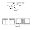
- ⁇ I p ⁇ represents the isophote at pixel p as illustrated on figure 7 .
- the value of D(Bi, Tj) lies in the range [0; 1].
- D(p) ⁇ 1 it is highly probable that the template Ti comprises a strong edge or structure.
- D(Bi,Tj) median ( D ( p ), p ⁇ ⁇ n B i ).
- the value of D(p) is for example computed as follows :
- ⁇ can take the value 0.9.
- the block B next with the highest priority level P max is identified. If two blocks have the same priority that is equal to P max , the first block encountered when scanning the picture blocks from top to bottom and left to right is identified.
- the module 14 encodes a part of the picture comprising the block B next whose priority level is the highest.
- the block B next is a macroblock MB next .
- the block B next is a block smaller than a macroblock.
- a macroblock MB next encompassing the block B next is identified.
- the macroblock MB next is thus encoded.
- the blocks inside the macroblock MB next are scanned according to a classical zig-zag scan order as depicted on figure 8(a) : top left block first followed by top right block, bottom left block and bottom right block.
- the zig-zag scan order of the blocks within the macroblock is adapted on the basis of the position of the reconstructed part (or causal neighborhood) with respect to the macroblock as depicted on figure 8 .
- the reconstructed part on the border of the macroblock is represented in grey.
- the blocks within the macroblock are associated with an index which indicates the order of coding. Consequently, the block with the highest priority value is not necessarily encoded first.
- the block with index 2 can be the one with the highest priority while the block on its right is encoded first.
- the step S10 and S12 are iterated within the macroblock MB next to determine the encoding order to the blocks within the macroblock. In this case, the scan order of the blocks within the macroblock is not a zig-zag scan order anymore but is adapted to content.
- Encoding a block usually comprises determining a predictor, calculating residues between the block and the predictor.
- the residues are then transformed (e.g. by a DCT like transform, where DCT is the English acronym of "Discrete Cosine Transform") and quantized before being entropy coded in a bitstream.
- Determining a predictor comprises determining a prediction mode which is also encoded in the bitstream.
- a block can be predicted in various ways.
- Well-known prediction techniques are directional intra prediction as defined in H.264 and HEVC coding standards, template based prediction (e.g. template matching), multi-patches based prediction (e.g Non local mean (NLM), Locally linear embedding (LLE)) are other examples of such prediction techniques.
- the highest priority level determined in step S10 is associated with one of the template defined on figure 5a or 5b . This template is used for determining the predictor in the template and multi-patches based prediction methods for the block B next .
- the directional intra predictions as defined in H.264 coding standard require a classical raster scan order of macroblock and zig-zag scan within the macroblock.
- the causal neighborhood ie. the neighborhood comprising reconstructed pixels
- the causal neighborhood can be located anywhere around the block.
- the directional intra predictions as defined in H.264 are thus adapted. Specifically, a rotation by 90°, by 180° and by 270° is applied on all the directional intra predictions to obtain directional intra predictions adapted to the various causal neighborhoods.
- the index of the mode as defined in H.264 is kept whatever the orientation.
- the horizontal prediction mode is always associated with the index 1 even when the pixel on the right are used for prediction.
- Figure 9 represents the directional intra prediction modes for a causal neighborhood located on the top and on the right of a block to encode. These prediction modes correspond to the modes defined in H.264 and rotated by 90° on the right.
- the selection of one prediction mode among the various prediction modes can be made according to a well-known rate-distortion technique, i.e. the prediction mode that provides the best compromise in terms of reconstruction error and bit-rate is selected.
- the steps S10 and S12 can be iterated until the whole picture is encoded.
- the method can also be applied on each picture of a sequence of pictures to encode the whole sequence.
- the bitstream F is for example transmitted to a destination by the output 16 of the encoding device 1.
- Figure 10 depicts a device 2 for decoding a picture divided into blocks according to a specific and non-limitative embodiment of the invention.
- the decoding device 2 comprises an input 20 configured to receive a bitstream from a source.
- the input 20 is linked to a module 22 configured to determine for at least two blocks adjacent to a reconstructed part of the picture a priority level responsive at least to the number of reconstructed pixels within a patch comprising the block.
- the reconstructed part is a portion of the picture already decoded.
- the reconstructed part can also be named decoded part.
- the reconstructed part can be the first line of macroblocks in the picture Y which is decoded in a raster scan order.
- the reconstructed part can be a block/macroblock located at specific positions in the picture, e.g. in the center of the picture.
- the reconstructed part is an epitome of the picture Y.
- An epitome is a condensed representation of a picture.
- the epitome is made of patches of texture belonging to the picture Y.
- the reconstructed part can be used for prediction of other part of the picture not yet decoded.
- a block is adjacent to a reconstructed part of the picture if one of its border is along the reconstructed part.
- the module 22 is linked to a module 24 adapted to decode a part of the picture comprising the block whose priority level is the highest.
- the module 24 is linked to an output 26.
- Figure 11 represents an exemplary architecture of the decoding device 2 configured to decode a picture Y from a bitstream, wherein the picture is divided into blocks according to an exemplary embodiment of the invention.
- the decoding device 2 comprises one or more processor(s) 210 , which is(are), for example, a CPU, a GPU and/or a DSP (English acronym of Digital Signal Processor), along with internal memory 220 (e.g. RAM, ROM, EPROM).
- the decoding device 2 comprises one or several Input/Output interface(s) 230 adapted to display output information and/or allow a user to enter commands and/or data (e.g.
- the decoding device 2 may also comprise network interface(s) (not shown).
- the bitstream may be obtained from a source.
- the source belongs to a set comprising:
- Figure 12 represents a flowchart of a method for decoding a picture from a bitstream F, wherein the picture is divided into blocks according to a specific and non-limitative embodiment of the invention.
- the bitstream F is for example received on the input 20 of the decoding device.
- a step S20 the module 22 determines for at least two blocks adjacent to a reconstructed part of the picture Y a priority level responsive at least to the number of reconstructed pixels within a patch comprising the block.
- a block can be a macroblock.
- the step S20 is identical to the step S10 on the encoding side. Consequently, the step S20 is not further disclosed. All the variants disclosed with respect to the encoding method for step S10 apply to S20.
- the module 24 decodes a part of the picture comprising the block whose priority level is the highest.
- the block B next is a macroblock MB next .
- the block B next is a block smaller than a macroblock.
- a macroblock MB next encompassing the block B next is identified.
- the macroblock MB next is thus decoded.
- the blocks inside the macroblock are scanned according to a classical zig-zag scan order as depicted on figure 8(a) : top left block first followed by top right block, bottom left block and bottom right block.
- the zig-zag scan order of the blocks within the macroblock is adapted on the basis of the position of the reconstructed part with respect to the macroblock as depicted on figure 8 . Consequently, the block with the highest priority value is not necessarily decoded first.
- the block with index 2 can be the one with the highest priority while the block on its right is decoded first.
- Decoding a block usually comprises determining a predictor and residues. Determining the residues comprises entropy decoding of a part of the bitstream F representative of the block to obtain coefficients, dequantizing and transforming the coefficients to obtain residues. The residues are added to the predictor to obtain a decoded block.
- the transforming on the decoding side is the inverse of the transforming on the encoder side.
- Determining a predictor comprises determining a prediction mode which is usually decoded from the bitstream.
- the highest priority level determined in step S20 is associated with one of the template defined on figure 5a or 5b . This template is used for determining the predictor in the template based prediction methods for the block B next .
- the steps S20 and S22 can be iterated until the whole picture is decoded.
- the method can also be applied on each picture of a sequence of pictures to decode the whole sequence.
- the decoded picture is for example sent to a destination by the output 26 of the decoding device 2.
- the implementations described herein may be implemented in, for example, a method or a process, an apparatus, a software program, a data stream, or a signal. Even if only discussed in the context of a single form of implementation (for example, discussed only as a method or a device), the implementation of features discussed may also be implemented in other forms (for example a program).
- An apparatus may be implemented in, for example, appropriate hardware, software, and firmware.
- the methods may be implemented in, for example, an apparatus such as, for example, a processor, which refers to processing devices in general, including, for example, a computer, a microprocessor, an integrated circuit, or a programmable logic device. Processors also include communication devices, such as, for example, computers, cell phones, portable/personal digital assistants ("PDAs”), and other devices that facilitate communication of information between end-users.
- PDAs portable/personal digital assistants
- Implementations of the various processes and features described herein may be embodied in a variety of different equipment or applications, particularly, for example, equipment or applications.
- equipment examples include an encoder, a decoder, a post-processor processing output from a decoder, a pre-processor providing input to an encoder, a video coder, a video decoder, a video codec, a web server, a set-top box, a laptop, a personal computer, a cell phone, a PDA, and other communication devices.
- the equipment may be mobile and even installed in a mobile vehicle.
- the methods may be implemented by instructions being performed by a processor, and such instructions (and/or data values produced by an implementation) may be stored on a processor-readable medium such as, for example, an integrated circuit, a software carrier or other storage device such as, for example, a hard disk, a compact diskette (“CD"), an optical disc (such as, for example, a DVD, often referred to as a digital versatile disc or a digital video disc), a random access memory (“RAM”), or a read-only memory (“ROM”).
- the instructions may form an application program tangibly embodied on a processor-readable medium. Instructions may be, for example, in hardware, firmware, software, or a combination.
- a processor may be characterized, therefore, as, for example, both a device configured to carry out a process and a device that includes a processor-readable medium (such as a storage device) having instructions for carrying out a process. Further, a processor-readable medium may store, in addition to or in lieu of instructions, data values produced by an implementation.
- implementations may produce a variety of signals formatted to carry information that may be, for example, stored or transmitted.
- the information may include, for example, instructions for performing a method, or data produced by one of the described implementations.
- a signal may be formatted to carry as data the rules for writing or reading the syntax of a described embodiment, or to carry as data the actual syntax-values written by a described embodiment.
- Such a signal may be formatted, for example, as an electromagnetic wave (for example, using a radio frequency portion of spectrum) or as a baseband signal.
- the formatting may include, for example, encoding a data stream and modulating a carrier with the encoded data stream.
- the information that the signal carries may be, for example, analog or digital information.
- the signal may be transmitted over a variety of different wired or wireless links, as is known.
- the signal may be stored on a processor-readable medium.
- the invention finds its interest in all domains concerned with the image epitome reduction. Applications related to video compression and representations of videos are concerned.
Landscapes
- Engineering & Computer Science (AREA)
- Multimedia (AREA)
- Signal Processing (AREA)
- Compression Or Coding Systems Of Tv Signals (AREA)
Abstract
a) determining (S20) for at least two blocks adjacent to a reconstructed part of the picture a priority level responsive at least to the number of reconstructed pixels within a patch comprising the block; and
b) decoding (S22) a part of the picture comprising the block whose priority level is the highest.
Description
- In the following, a method and a device for encoding a picture are disclosed. Corresponding decoding method and decoding device are further disclosed.
- It is known to encode a picture divided into blocks by processing the blocks according to a predefined scan order. The scan order is usually specified in a coding standard (e.g. H.264, HEVC). The same scan order is used in the encoder and in the decoder. Exemplarily, in H.264 coding standard, macroblocks which are blocks of 16 by 16 pixels are processed line by line in a raster scan order. In a macroblock, the blocks are further processed according to a zig-zag scan order as depicted on
Figure 1 . Using such predefined scan orders may decrease the coding efficiency. - A method for decoding a picture divided into blocks is disclosed. The method comprises at least one iteration of:
- a) determining for at least two blocks adjacent to a reconstructed part of the picture a priority level responsive at least to the number of reconstructed pixels within a patch comprising the block; and
- b) decoding a part of the picture comprising the block whose priority level is the highest.
- Advantageously, the priority level is further determined based on whether the block is on the continuation of strong edges or structures.
- According to a specific embodiment, the reconstructed part belongs to the group comprising:
- the blocks located on the borders of the picture;
- an epitome of the picture;
- a block located in the center of the picture.
- In a specific embodiment, in step b), the part of the picture comprising the block whose priority level is the highest is a macroblock and decoding the macroblock comprises at least one iteration of:
- c) determining for at least two blocks in the macroblock adjacent to the reconstructed part of the picture a priority level; and
- d) decoding first the block of said macroblock whose priority level is the highest.
- In variant, in step b), the part of the picture comprising the block whose priority level is the highest is a macroblock and decoding said macroblock comprises:
- determining a zig-zag scan order of blocks within the macroblock on the basis of at least the spatial position of a causal neighborhood with respect to the macroblock;
- decoding said blocks within the macroblock according to said zig-zag scan order.
- According to a specific characteristic, the part of the picture comprising the block whose priority level is the highest is a macroblock encompassing said block.
- In a variant, the at least two blocks are macroblocks and the part of the picture comprising the block whose priority level is the highest is the macroblock whose priority level is the highest.
- A method for encoding a picture divided into blocks is further disclosed. The encoding method comprises at least one iteration of:
- a) determining for at least two blocks adjacent to a reconstructed part of the picture a priority level responsive at least to the number of reconstructed pixels within a patch comprising the block; and
- b) encoding a part of the picture comprising the block whose priority level is the highest.
- Advantageously, the priority level is further determined based on whether the block is on the continuation of strong edges or structures.
- A device for decoding a picture divided into blocks is disclosed that comprises at least one processor configured to:
- determine for at least two blocks adjacent to a reconstructed part of the picture a priority level responsive at least to the number of reconstructed pixels within a patch comprising the block; and
- decode a part of the picture comprising the block whose priority level is the highest.
- A device for decoding a picture divided into blocks is also disclosed that comprises:
- means for determining for at least two blocks adjacent to a reconstructed part of the picture a priority level responsive at least to the number of reconstructed pixels within a patch comprising the block; and
- means for decoding a part of the picture comprising the block whose priority level is the highest.
- The devices for decoding are configured to execute the steps of the decoding method according to any of the embodiments and variants disclosed.
- A device for encoding a picture divided into blocks is disclosed that comprises at least one processor configured to:
- determine for at least two blocks adjacent to a reconstructed part of the picture a priority level responsive at least to the number of reconstructed pixels within a patch comprising the block; and
- encode a part of the picture comprising the block whose priority level is the highest.
- A device for encoding a picture divided into blocks is disclosed that comprises:
- means for determining for at least two blocks adjacent to a reconstructed part of the picture a priority level responsive at least to the number of reconstructed pixels within a patch comprising the block; and
- means for encoding a part of the picture comprising the block whose priority level is the highest.
- The devices for encoding are configured to execute the steps of the encoding method according to any of the embodiments and variants disclosed.
- A computer program product is disclosed that comprises program code instructions to execute of the steps of the decoding method according to any of the embodiments and variants disclosed when this program is executed on a computer.
- A processor readable medium is disclosed that has stored therein instructions for causing a processor to perform at least the steps of the decoding method according to any of the embodiments and variants disclosed.
- A computer program product is disclosed that comprises program code instructions to execute of the steps of the encoding method according to any of the embodiments and variants disclosed when this program is executed on a computer.
- A processor readable medium is disclosed that has stored therein instructions for causing a processor to perform at least the steps of the encoding method according to any of the embodiments and variants disclosed.
- In the drawings, an embodiment of the present invention is illustrated. It shows:
-
Figure 1 depicts a picture Y divided into blocks that are processed according to a classical raster scan order; -
Figure 2 depicts a device for encoding a picture divided into blocks according to a specific and non-limitative embodiment of the invention; -
Figure 3 represents an exemplary architecture of an encoding device according to a specific and non-limitative embodiment of the invention; -
Figure 4 represents a flowchart of a method for encoding a picture Y in a bitstream according to a specific and non-limitative embodiment of the invention; -
Figure 5a depicts a set of patches defined according to a specific and non-limitative embodiment of the invention; -
Figure 5b depicts additional patches defined according to a specific and non-limitative embodiment of the invention; -
Figure 6 represents a picture Y comprising a reconstructed part delimited by a frontier δΩ and blocks to be coded/decoded; -
Figure 7 represents a picture part comprising a reconstructed part delimited by a frontier δΩ; -
Figure 8 shows various scan orders of blocks within a macroblock that depend on the position of a causal neighborhood with respect to the macroblock; -
Figure 9 represents various directional intra prediction modes adapted according to a specific and non-limitative embodiment of the invention; -
Figure 10 depicts a device for decoding a picture divided into blocks according to a specific and non-limitative embodiment of the invention. -
Figure 11 represents an exemplary architecture of an decoding device according to a specific and non-limitative embodiment of the invention; and -
Figure 12 represents a flowchart of a method for decoding a picture Y from a bitstream according to a specific and non-limitative embodiment of the invention. - The words "decoded" and "reconstructed" are often used as synonyms. Usually but not necessarily, the word "reconstructed" is used on the encoder side and the word "decoded" is used on the decoder side. A causal neighborhood is a neighborhood of a block comprising pixels of the reconstructed part.
-
Figure 2 depicts adevice 1 for encoding a picture Y divided into blocks according to a specific and non-limitative embodiment of the invention.
Theencoding device 1 comprises aninput 10 configured to receive at least one picture from a source. Theinput 10 is linked to amodule 12 configured to determine, for at least two blocks adjacent to a reconstructed part of the picture, a priority level responsive at least to the number of reconstructed pixels within a patch comprising the block. A block is adjacent to a reconstructed part of the picture if one of its border is along the reconstructed part. The reconstructed part is a portion of the picture already encoded and reconstructed. As an example, the reconstructed part can be the first line of macroblocks in the picture Y which is encoded in a raster scan order. According to a variant, the reconstructed part can be a block/macroblock located at specific positions in the picture, e.g. in the center of the picture. According to yet another variant, the reconstructed part is an epitome of the picture Y. An epitome is a condensed representation of a picture. As an example the epitome is made of patches of texture belonging to the picture Y. On the encoder side, the reconstructed part can be used for prediction of other part of the picture not yet encoded. Themodule 12 is linked to amodule 14 adapted to encode a part of the picture comprising the block whose priority level is the highest in a bitstream. Themodule 14 is linked to anoutput 16. The bitstream can be stored in a memory internal to thecoding device 1 or external to it. According to a variant the bitstream can be sent to a destination. -
Figure 3 represents an exemplary architecture of theencoding device 1 according to a specific and non-limitative embodiment of the invention. Theencoding device 1 comprises one or more processor(s) 110 , which is(are), for example, a CPU, a GPU and/or a DSP (English acronym of Digital Signal Processor), along with internal memory 120 (e.g. RAM, ROM, EPROM). Theencoding device 1 comprises one or several Input/Output interface(s) 130 adapted to display output information and/or allow a user to enter commands and/or data (e.g. a keyboard, a mouse, a touchpad, a webcam); and apower source 140 which may be external to theencoding device 1. Theencoding device 1 may also comprise network interface(s) (not shown). The picture Y may be obtained from a source. According to different embodiments of the invention, the source belongs to a set comprising: - a local memory, e.g. a video memory, a RAM, a flash memory, a hard disk ;
- a storage interface, e.g. an interface with a mass storage, a ROM, an optical disc or a magnetic support;
- a communication interface, e.g. a wireline interface (for example a bus interface, a wide area network interface, a local area network interface) or a wireless interface (such as a IEEE 802.11 interface or a Bluetooth interface); and
- an image capturing circuit (e.g. a sensor such as, for example, a CCD (or Charge-Coupled Device) or CMOS (or Complementary Metal-Oxide-Semiconductor)).
- a mobile device ;
- a communication device ;
- a game device ;
- a tablet (or tablet computer) ;
- a laptop ;
- a still image camera;
- a video camera ;
- an encoding chip;
- a still image server ; and
- a video server (e.g. a broadcast server, a video-on-demand server or a web server).
-
Figure 4 represents a flowchart of a method for encoding a picture Y in a bitstream F, wherein the picture Y is divided into blocks according to a specific and non-limitative embodiment of the invention. The picture Y is for example received from a source on theinput 10 of theencoding device 1. - In a step S10, the
module 12 determines for at least two blocks adjacent to a reconstructed part of the picture a priority level responsive at least to the number of reconstructed pixels within a patch comprising the block. A block can be a macroblock.Figure 5a depicts a set of 8 patches that comprises a block and a template. A patch is thus larger than a block. On this figure, the pixels whose value is zero are pixels of a current block whose priority value is to be calculated and the pixels whose value is 1 are pixels of the template. In a variant, additional templates are used such as the templates depicted onFigure 5 b. According to a variant, only a subset of the templates defined onfigures 5a and5b are used. On thefigures 5a and5b , the width of the templates is equal to 3 pixels. In a variant, the width can be larger than 3, e.g. 4 pixels or smaller than 3, e.g. 2 pixels. In the following, only the templates offigure 5a are considered. Depending on the position the current block with respect to the reconstructed part a single template or a plurality of templates in the set of 8 templates depicted onfigures 5a are considered.Figure 6 represents a picture Y comprising a reconstructed part delimited by a frontier δΩ. δΩ comprises pixels located inside the reconstructed part. Onfigure 6 , blocks B1 to B6 are identified that are adjacent to the reconstructed part. The block B1 is located in such a way with respect to the reconstructed part that only the template T7 can be used for determining the priority level of this block. For the block B2, the following templates can be used: T1, T3, T5, T6 and T7. For the block B3, the following templates can be used: T1, T5 and T6. For the block B4, the following templates can be used: T2, T6 and T8. For the block B5, the following templates can be used: T4, T7 and T8. B6 is a block no yet encoded surrounded by the reconstructed part. For B6, all the templates can be used. The priority level P(Bi) is determined for a given block Bi, where i is an index identifying the block, as follows: - calculating for each template Tj, where j is an index identifying the template that can be used for the block Bi, the ratio C(Bi, Tj) between the number of pixels in the template and the number of pixels in the patch ;
- determining the highest ratio and setting the priority value for the block equal to the highest ratio, i.e. P(Bi) is equal to maxj(C(Bi, Tj)).
- calculating for each template Tj that can be used for the block Bi, the product of C(Bi, Tj) and D(Bi, Tj); and
- determining the highest product and setting the priority value for the block equal to the highest product, i.e. P(Bi) thus equal maxj(C(Bi, Tj)*D(Bi, Tj)). The value of second term D(Bi, Tj) is based on whether the block is on the continuation of strong edges or structures.
- When using this second term the reconstruction of linear structures localized on the borders of the block is privileged which may then improve the prediction and thus the coding efficiency. The method aims at extending linear structure into the to be coded block of the boundary pixels.
This second term is a function that specifies the strength of the isophotes arriving on δΩ. The term isophote designates linear structures in inpainting literature as mentioned in the document from Criminisi et al entitled "Region filling and object removal by exemplar-based image inpainting" and published in IEEE Transactions on Image Processing, vol.13, n°9, September 2004. The second term is for example defined as follows: D(Bi, Tj) = max(D(p), p ∈ δΩ ∩ Bi) with
p is a pixel adjacent to Bi located on the frontier δΩ of the reconstructed part. α is a normalization factor (e.g. α = 255 for a grey level picture) and np is a unit vector orthogonal to the frontier δΩ at pixel p.
figure 7 . The value of D(Bi, Tj) lies in the range [0; 1]. When D(p) → 1, it is highly probable that the template Ti comprises a strong edge or structure. Inequation 1, the function max() can be replaced by a mean() or median() function, e.g. D(Bi,Tj) = median(D(p),p ∈ δΩ n Bi ). The value of D(p) is for example computed as follows : - calculating the gradient Gx (p) at p(x,y) by applying a filter Fx where (x,y) are the components of pixel p. The value of Fx varies as follows depending on the availability of pixels adjacent to p(x, y) and located on the same line:
- i. if p(x-1,y) and p(x+1,y) are known, i.e. reconstructed, Fx = [-1,0,1]
- ii. If only p(x+1,y) is known, Fx = [-0.5,0,5]
- iii. If only p(x-1,y) is known, Fx = [0.5, - 0,5]
- calculating the gradient Gy(p) at p by applying a filter Fy. The value of Fy varies as follows depending on the availability of pixels adjacent to p(x, y) and located on the same column:
- i. if p(x,y-1) et p(x,y+1) are known, Fy = [-1,0,1] Tr
- ii. If only p(x,y+1) is known, Fy = [-0.5,0,5] Tr
- iii. If only p(x,y-1) is known, Fy = [0.5, - 0,5] Tr
- calculating the isophote (Isox (p),Isoy (p)) at p by applying a rotation by 90° on the gradient, i.e. Isox (p) = -Gy (p) et Isoy (p) = Gx (p)
- calculating the scalar product between the isophote after normalization by α and the unit vector that is orthogonal to δΩ after normalization:


- Once the priority P(Bi) is determined for at least two blocks adjacent to the frontier δΩ, the block Bnext with the highest priority level Pmax is identified. If two blocks have the same priority that is equal to Pmax, the first block encountered when scanning the picture blocks from top to bottom and left to right is identified.
- In a step S12, the
module 14 encodes a part of the picture comprising the block Bnext whose priority level is the highest. According to a first embodiment, the block Bnext is a macroblock MBnext. According to a variant, the block Bnext is a block smaller than a macroblock. In the latter case, a macroblock MBnext encompassing the block Bnext is identified. The macroblock MBnext is thus encoded. To this aim, the blocks inside the macroblock MBnext are scanned according to a classical zig-zag scan order as depicted onfigure 8(a) : top left block first followed by top right block, bottom left block and bottom right block. According to a variant, the zig-zag scan order of the blocks within the macroblock is adapted on the basis of the position of the reconstructed part (or causal neighborhood) with respect to the macroblock as depicted onfigure 8 . On this figure the reconstructed part on the border of the macroblock is represented in grey. The blocks within the macroblock are associated with an index which indicates the order of coding. Consequently, the block with the highest priority value is not necessarily encoded first. For example, with respect tofigure 8(b) the block withindex 2 can be the one with the highest priority while the block on its right is encoded first. According to yet another variant, the step S10 and S12 are iterated within the macroblock MBnext to determine the encoding order to the blocks within the macroblock. In this case, the scan order of the blocks within the macroblock is not a zig-zag scan order anymore but is adapted to content. - Encoding a block usually comprises determining a predictor, calculating residues between the block and the predictor. The residues are then transformed (e.g. by a DCT like transform, where DCT is the English acronym of "Discrete Cosine Transform") and quantized before being entropy coded in a bitstream.
- Determining a predictor comprises determining a prediction mode which is also encoded in the bitstream. Indeed, a block can be predicted in various ways. Well-known prediction techniques are directional intra prediction as defined in H.264 and HEVC coding standards, template based prediction (e.g. template matching), multi-patches based prediction (e.g Non local mean (NLM), Locally linear embedding (LLE)) are other examples of such prediction techniques. According to a specific embodiment, the highest priority level determined in step S10 is associated with one of the template defined on
figure 5a or5b . This template is used for determining the predictor in the template and multi-patches based prediction methods for the block Bnext.
The directional intra predictions as defined in H.264 coding standard require a classical raster scan order of macroblock and zig-zag scan within the macroblock. In this case, the causal neighborhood (ie. the neighborhood comprising reconstructed pixels) used for the directional intra prediction is always located on the left and/or on the top of the block. With the adaptive scanning order according to the invention, the causal neighborhood can be located anywhere around the block. The directional intra predictions as defined in H.264 are thus adapted. Specifically, a rotation by 90°, by 180° and by 270° is applied on all the directional intra predictions to obtain directional intra predictions adapted to the various causal neighborhoods. The index of the mode as defined in H.264 is kept whatever the orientation. Exemplarily, the horizontal prediction mode is always associated with theindex 1 even when the pixel on the right are used for prediction.Figure 9 represents the directional intra prediction modes for a causal neighborhood located on the top and on the right of a block to encode. These prediction modes correspond to the modes defined in H.264 and rotated by 90° on the right.
The selection of one prediction mode among the various prediction modes can be made according to a well-known rate-distortion technique, i.e. the prediction mode that provides the best compromise in terms of reconstruction error and bit-rate is selected.
Once a block or a macroblock is encoded and reconstructed, the steps S10 and S12 can be iterated until the whole picture is encoded. The method can also be applied on each picture of a sequence of pictures to encode the whole sequence.
The bitstream F is for example transmitted to a destination by theoutput 16 of theencoding device 1. -
Figure 10 depicts adevice 2 for decoding a picture divided into blocks according to a specific and non-limitative embodiment of the invention.
Thedecoding device 2 comprises aninput 20 configured to receive a bitstream from a source. Theinput 20 is linked to amodule 22 configured to determine for at least two blocks adjacent to a reconstructed part of the picture a priority level responsive at least to the number of reconstructed pixels within a patch comprising the block. The reconstructed part is a portion of the picture already decoded. On the decoder side, the reconstructed part can also be named decoded part. As an example, the reconstructed part can be the first line of macroblocks in the picture Y which is decoded in a raster scan order. According to a variant, the reconstructed part can be a block/macroblock located at specific positions in the picture, e.g. in the center of the picture. According to yet another variant, the reconstructed part is an epitome of the picture Y. An epitome is a condensed representation of a picture. As an example the epitome is made of patches of texture belonging to the picture Y. On the decoder side, the reconstructed part can be used for prediction of other part of the picture not yet decoded. A block is adjacent to a reconstructed part of the picture if one of its border is along the reconstructed part. Themodule 22 is linked to amodule 24 adapted to decode a part of the picture comprising the block whose priority level is the highest. Themodule 24 is linked to anoutput 26. When a picture is decoded, it can be stored in a memory internal to thedecoding device 2 or external to it. According to a variant the decoded picture can be sent to a destination. -
Figure 11 represents an exemplary architecture of thedecoding device 2 configured to decode a picture Y from a bitstream, wherein the picture is divided into blocks according to an exemplary embodiment of the invention. Thedecoding device 2 comprises one or more processor(s) 210 , which is(are), for example, a CPU, a GPU and/or a DSP (English acronym of Digital Signal Processor), along with internal memory 220 (e.g. RAM, ROM, EPROM). Thedecoding device 2 comprises one or several Input/Output interface(s) 230 adapted to display output information and/or allow a user to enter commands and/or data (e.g. a keyboard, a mouse, a touchpad, a webcam); and apower source 240 which may be external to thedecoding device 2. Thedecoding device 2 may also comprise network interface(s) (not shown). The bitstream may be obtained from a source. According to different embodiments of the invention, the source belongs to a set comprising: - a local memory, e.g. a video memory, a RAM, a flash memory, a hard disk ;
- a storage interface, e.g. an interface with a mass storage, a ROM, an optical disc or a magnetic support;
- a communication interface, e.g. a wireline interface (for example a bus interface, a wide area network interface, a local area network interface) or a wireless interface (such as a IEEE 802.11 interface or a Bluetooth interface); and
- an image capturing circuit (e.g. a sensor such as, for example, a CCD (or Charge-Coupled Device) or CMOS (or Complementary Metal-Oxide-Semiconductor)).
- a mobile device ;
- a communication device ;
- a game device ;
- a set top box;
- a TV set;
- a tablet (or tablet computer) ;
- a laptop ;
- a display and
- a decoding chip.
-
Figure 12 represents a flowchart of a method for decoding a picture from a bitstream F, wherein the picture is divided into blocks according to a specific and non-limitative embodiment of the invention. The bitstream F is for example received on theinput 20 of the decoding device. - In a step S20, the
module 22 determines for at least two blocks adjacent to a reconstructed part of the picture Y a priority level responsive at least to the number of reconstructed pixels within a patch comprising the block. A block can be a macroblock. The step S20 is identical to the step S10 on the encoding side. Consequently, the step S20 is not further disclosed. All the variants disclosed with respect to the encoding method for step S10 apply to S20. - In a step S22, the
module 24 decodes a part of the picture comprising the block whose priority level is the highest. According to a first embodiment, the block Bnext is a macroblock MBnext. According to a variant, the block Bnext is a block smaller than a macroblock. In the latter case, a macroblock MBnext encompassing the block Bnext is identified. The macroblock MBnext is thus decoded. To this aim, the blocks inside the macroblock are scanned according to a classical zig-zag scan order as depicted onfigure 8(a) : top left block first followed by top right block, bottom left block and bottom right block. According to a variant, the zig-zag scan order of the blocks within the macroblock is adapted on the basis of the position of the reconstructed part with respect to the macroblock as depicted onfigure 8 . Consequently, the block with the highest priority value is not necessarily decoded first. For example, with respect tofigure 8(b) the block withindex 2 can be the one with the highest priority while the block on its right is decoded first.
Decoding a block usually comprises determining a predictor and residues. Determining the residues comprises entropy decoding of a part of the bitstream F representative of the block to obtain coefficients, dequantizing and transforming the coefficients to obtain residues. The residues are added to the predictor to obtain a decoded block. The transforming on the decoding side is the inverse of the transforming on the encoder side.
Determining a predictor comprises determining a prediction mode which is usually decoded from the bitstream. According to a specific embodiment, the highest priority level determined in step S20 is associated with one of the template defined onfigure 5a or5b . This template is used for determining the predictor in the template based prediction methods for the block Bnext.
Once a block or a macroblock is decoded, the steps S20 and S22 can be iterated until the whole picture is decoded. The method can also be applied on each picture of a sequence of pictures to decode the whole sequence.
The decoded picture is for example sent to a destination by theoutput 26 of thedecoding device 2. - The implementations described herein may be implemented in, for example, a method or a process, an apparatus, a software program, a data stream, or a signal. Even if only discussed in the context of a single form of implementation (for example, discussed only as a method or a device), the implementation of features discussed may also be implemented in other forms (for example a program). An apparatus may be implemented in, for example, appropriate hardware, software, and firmware. The methods may be implemented in, for example, an apparatus such as, for example, a processor, which refers to processing devices in general, including, for example, a computer, a microprocessor, an integrated circuit, or a programmable logic device. Processors also include communication devices, such as, for example, computers, cell phones, portable/personal digital assistants ("PDAs"), and other devices that facilitate communication of information between end-users.
- Implementations of the various processes and features described herein may be embodied in a variety of different equipment or applications, particularly, for example, equipment or applications. Examples of such equipment include an encoder, a decoder, a post-processor processing output from a decoder, a pre-processor providing input to an encoder, a video coder, a video decoder, a video codec, a web server, a set-top box, a laptop, a personal computer, a cell phone, a PDA, and other communication devices. As should be clear, the equipment may be mobile and even installed in a mobile vehicle.
- Additionally, the methods may be implemented by instructions being performed by a processor, and such instructions (and/or data values produced by an implementation) may be stored on a processor-readable medium such as, for example, an integrated circuit, a software carrier or other storage device such as, for example, a hard disk, a compact diskette ("CD"), an optical disc (such as, for example, a DVD, often referred to as a digital versatile disc or a digital video disc), a random access memory ("RAM"), or a read-only memory ("ROM"). The instructions may form an application program tangibly embodied on a processor-readable medium. Instructions may be, for example, in hardware, firmware, software, or a combination. Instructions may be found in, for example, an operating system, a separate application, or a combination of the two. A processor may be characterized, therefore, as, for example, both a device configured to carry out a process and a device that includes a processor-readable medium (such as a storage device) having instructions for carrying out a process. Further, a processor-readable medium may store, in addition to or in lieu of instructions, data values produced by an implementation.
- As will be evident to one of skill in the art, implementations may produce a variety of signals formatted to carry information that may be, for example, stored or transmitted. The information may include, for example, instructions for performing a method, or data produced by one of the described implementations. For example, a signal may be formatted to carry as data the rules for writing or reading the syntax of a described embodiment, or to carry as data the actual syntax-values written by a described embodiment. Such a signal may be formatted, for example, as an electromagnetic wave (for example, using a radio frequency portion of spectrum) or as a baseband signal. The formatting may include, for example, encoding a data stream and modulating a carrier with the encoded data stream. The information that the signal carries may be, for example, analog or digital information. The signal may be transmitted over a variety of different wired or wireless links, as is known. The signal may be stored on a processor-readable medium.
- A number of implementations have been described. Nevertheless, it will be understood that various modifications may be made. For example, elements of different implementations may be combined, supplemented, modified, or removed to produce other implementations. Additionally, one of ordinary skill will understand that other structures and processes may be substituted for those disclosed and the resulting implementations will perform at least substantially the same function(s), in at least substantially the same way(s), to achieve at least substantially the same result(s) as the implementations disclosed. Accordingly, these and other implementations are contemplated by this application.
- The invention finds its interest in all domains concerned with the image epitome reduction. Applications related to video compression and representations of videos are concerned.
According to an exemplary and non-limitative embodiment of the invention, the
According to exemplary and non-limitative embodiments, the

According to a variant, the priority level P(Bi) is determined for a given block Bi as follows:

According to an exemplary and non-limitative embodiment of the invention, the
According to exemplary and non-limitative embodiments, the
Claims (15)
- A method for decoding a picture divided into blocks comprising at least one iteration of:a) determining (S20) for at least two blocks adjacent to a reconstructed part of the picture a priority level responsive at least to the number of reconstructed pixels within a patch comprising the block; andb) decoding (S22) a part of the picture comprising the block whose priority level is the highest.
- The method of claim 1, wherein the priority level is further determined based on whether the block is on the continuation of strong edges or structures.
- The method according to claim 1 or 2, wherein the reconstructed part belongs to the group comprising:- the blocks located on the borders of the picture;- an epitome of the picture;- a block located in the center of the picture.
- The method according to any of claims 1 to 3, wherein, in step b), the part of the picture comprising the block whose priority level is the highest is a macroblock and wherein decoding said macroblock comprises at least one iteration of:a) determining for at least two blocks in the macroblock adjacent to the reconstructed part of the picture a priority level; andb) decoding first the block of said macroblock whose priority level is the highest.
- The method according to any of claims 1 to 3, wherein, in step b), the part of the picture comprising the block whose priority level is the highest is a macroblock and wherein decoding said macroblock comprises:- determining a zig-zag scan order of blocks within the macroblock on the basis of at least the spatial position of a causal neighborhood with respect to the macroblock;- decoding said blocks within the macroblock according to said zig-zag scan order.
- The method according to any of claims 1 to 5, wherein the part of the picture comprising the block whose priority level is the highest is a macroblock encompassing said block.
- The method according to any of claims 1 to 5, wherein the at least two blocks are macroblocks and wherein the part of the picture comprising the block whose priority level is the highest is the macroblock whose priority level is the highest.
- A method for encoding a picture divided into blocks comprising at least one iteration of:a) determining (S10) for at least two blocks adjacent to a reconstructed part of the picture a priority level responsive at least to the number of reconstructed pixels within a patch comprising the block; andb) encoding (S12) a part of the picture comprising the block whose priority level is the highest.
- The method of claim 1, wherein the priority level is further determined based on whether the block is on the continuation of strong edges or structures.
- A device for decoding a picture divided into blocks comprising at least one processor (210) configured to:- determine (S20) for at least two blocks adjacent to a reconstructed part of the picture a priority level responsive at least to the number of reconstructed pixels within a patch comprising the block; and- decode (S22) a part of the picture comprising the block whose priority level is the highest.
- A device for decoding a picture divided into blocks comprising:- means for determining (22) for at least two blocks adjacent to a reconstructed part of the picture a priority level responsive at least to the number of reconstructed pixels within a patch comprising the block; and- means for decoding (24) a part of the picture comprising the block whose priority level is the highest.
- The device according to claim 11, wherein said device for decoding is configured to execute the steps of the decoding method according to any of claims 1 to 7.
- A device for encoding a picture divided into blocks comprising at least one processor configured to:- determine (S10) for at least two blocks adjacent to a reconstructed part of the picture a priority level responsive at least to the number of reconstructed pixels within a patch comprising the block; and- encode (S12) a part of the picture comprising the block whose priority level is the highest.
- A device for encoding a picture divided into blocks comprising:- means for determining (12) for at least two blocks adjacent to a reconstructed part of the picture a priority level responsive at least to the number of reconstructed pixels within a patch comprising the block; and- means for encoding (14) a part of the picture comprising the block whose priority level is the highest.
- The device according to claim 14, wherein said device for encoding is configured to execute the steps of the encoding method according to any of claims 8 or 9.
Priority Applications (1)
| Application Number | Priority Date | Filing Date | Title |
|---|---|---|---|
| EP14305149.8A EP2903276A1 (en) | 2014-02-04 | 2014-02-04 | Method for encoding and decoding a picture comprising inpainting of the picture epitome and corresponding devices |
Applications Claiming Priority (1)
| Application Number | Priority Date | Filing Date | Title |
|---|---|---|---|
| EP14305149.8A EP2903276A1 (en) | 2014-02-04 | 2014-02-04 | Method for encoding and decoding a picture comprising inpainting of the picture epitome and corresponding devices |
Publications (1)
| Publication Number | Publication Date |
|---|---|
| EP2903276A1 true EP2903276A1 (en) | 2015-08-05 |
Family
ID=50231090
Family Applications (1)
| Application Number | Title | Priority Date | Filing Date |
|---|---|---|---|
| EP14305149.8A Withdrawn EP2903276A1 (en) | 2014-02-04 | 2014-02-04 | Method for encoding and decoding a picture comprising inpainting of the picture epitome and corresponding devices |
Country Status (1)
| Country | Link |
|---|---|
| EP (1) | EP2903276A1 (en) |
Cited By (1)
| Publication number | Priority date | Publication date | Assignee | Title |
|---|---|---|---|---|
| CN106954074A (en) * | 2016-01-07 | 2017-07-14 | 青岛海信电器股份有限公司 | A kind of video data handling procedure and device |
Citations (2)
| Publication number | Priority date | Publication date | Assignee | Title |
|---|---|---|---|---|
| WO2010086544A1 (en) * | 2009-01-28 | 2010-08-05 | France Telecom | Method and device for encoding an image using a prediction mask decoding method and device and corresponding signals and computer programs |
| WO2010086548A1 (en) * | 2009-01-28 | 2010-08-05 | France Telecom | Method and device for encoding an image, method and device for decoding and corresponding computer programmes |
-
2014
- 2014-02-04 EP EP14305149.8A patent/EP2903276A1/en not_active Withdrawn
Patent Citations (2)
| Publication number | Priority date | Publication date | Assignee | Title |
|---|---|---|---|---|
| WO2010086544A1 (en) * | 2009-01-28 | 2010-08-05 | France Telecom | Method and device for encoding an image using a prediction mask decoding method and device and corresponding signals and computer programs |
| WO2010086548A1 (en) * | 2009-01-28 | 2010-08-05 | France Telecom | Method and device for encoding an image, method and device for decoding and corresponding computer programmes |
Non-Patent Citations (4)
| Title |
|---|
| CRIMINISI ET AL.: "Region filling and object removal by exemplar-based image inpainting", IEEE TRANSACTIONS ON IMAGE PROCESSING, vol. 13, no. 9, September 2004 (2004-09-01), XP011116342, DOI: doi:10.1109/TIP.2004.833105 |
| SAFA CHÉRIGUI ET AL: "EPITOME INPAINTING WITH IN-LOOP RESIDUE CODING FOR IMAGE COMPRESSION", 1 May 2014 (2014-05-01), XP055125645, Retrieved from the Internet <URL:http://hal.archives-ouvertes.fr/docs/00/99/44/18/PDF/Adaptive_scanning_ICIP_2014_final_embedded_font.pdf> [retrieved on 20140627] * |
| SAFA CHERIGUI ET AL: "Epitome-based image compression using translational sub-pel mapping", MULTIMEDIA SIGNAL PROCESSING (MMSP), 2011 IEEE 13TH INTERNATIONAL WORKSHOP ON, IEEE, 17 October 2011 (2011-10-17), pages 1 - 6, XP032027526, ISBN: 978-1-4577-1432-0, DOI: 10.1109/MMSP.2011.6093786 * |
| SHIODERA T ET AL: "Bidirectional intra prediction", 31. VCEG MEETING; 79. MPEG MEETING; 15-01-2007 - 16-01-2007;MARRAKECH; (VIDEO CODING EXPERTS GROUP OF ITU-T SG.16),, no. VCEG-AE14, 14 January 2007 (2007-01-14), XP030003517, ISSN: 0000-0157 * |
Cited By (2)
| Publication number | Priority date | Publication date | Assignee | Title |
|---|---|---|---|---|
| CN106954074A (en) * | 2016-01-07 | 2017-07-14 | 青岛海信电器股份有限公司 | A kind of video data handling procedure and device |
| CN106954074B (en) * | 2016-01-07 | 2019-12-20 | 青岛海信电器股份有限公司 | Video data processing method and device |
Similar Documents
| Publication | Publication Date | Title |
|---|---|---|
| US10425647B2 (en) | Method of residue differential pulse-code modulation for HEVC range extension | |
| CN108141612B (en) | Apparatus and method for encoding and decoding images | |
| Kim et al. | Hierarchical prediction and context adaptive coding for lossless color image compression | |
| US8483496B2 (en) | Image encoding/decoding system | |
| US10326990B2 (en) | Method of alternative transform for data compression | |
| US20130294508A1 (en) | Method and device for encoding and decoding by using parallel intraprediction by a coding unit | |
| US11153564B2 (en) | Systems and methods for processing a block of a digital image | |
| US11212527B2 (en) | Entropy-inspired directional filtering for image coding | |
| CN112352434B (en) | Method and apparatus for aspect-ratio-based filtering for intra prediction | |
| EP3151559A1 (en) | Method for coding and decoding a plurality of picture blocks and corresponding devices | |
| US9848204B2 (en) | Spatial prediction method and device, coding and decoding methods and devices | |
| EP2938074A1 (en) | Methods for encoding and decoding a picture and corresponding devices | |
| US20180359492A1 (en) | Method for encoding and decoding images, device for encoding and decoding images, and corresponding computer programs | |
| KR20110091849A (en) | Reduced DC Gain Mismatch and DC Leak in Superposition Conversion Process | |
| US11265575B2 (en) | Image and video processing apparatuses and methods | |
| US11159826B2 (en) | Method for encoding and decoding images, encoding and decoding device, and corresponding computer programs | |
| US9219926B2 (en) | Image encoding apparatus, image encoding method and program, image decoding apparatus, image decoding method and program | |
| EP2887667A1 (en) | Coding of high dynamic range images | |
| EP3026913A1 (en) | Scalable encoding and decoding methods and corresponding devices with combined intraprediction and interlayer prediction | |
| EP3046326A1 (en) | Method and device of construction of an epitome, coding and decoding methods and coding and decoding devices | |
| US20230300329A1 (en) | Picture processing method and video decoder | |
| RU2776033C1 (en) | Method for encoding the conversion coefficient based on high-frequency zeroing and equipment therefor | |
| JP6519185B2 (en) | Video encoder | |
| US20180109809A1 (en) | Voxel video coding | |
| EP3197159A1 (en) | Methods for coding and for decoding an image block and corresponding devices |
Legal Events
| Date | Code | Title | Description |
|---|---|---|---|
| PUAI | Public reference made under article 153(3) epc to a published international application that has entered the european phase |
Free format text: ORIGINAL CODE: 0009012 |
|
| 17P | Request for examination filed |
Effective date: 20140204 |
|
| AK | Designated contracting states |
Kind code of ref document: A1 Designated state(s): AL AT BE BG CH CY CZ DE DK EE ES FI FR GB GR HR HU IE IS IT LI LT LU LV MC MK MT NL NO PL PT RO RS SE SI SK SM TR |
|
| AX | Request for extension of the european patent |
Extension state: BA ME |
|
| RAP1 | Party data changed (applicant data changed or rights of an application transferred) |
Owner name: THOMSON LICENSING |
|
| 17P | Request for examination filed |
Effective date: 20160118 |
|
| RBV | Designated contracting states (corrected) |
Designated state(s): AL AT BE BG CH CY CZ DE DK EE ES FI FR GB GR HR HU IE IS IT LI LT LU LV MC MK MT NL NO PL PT RO RS SE SI SK SM TR |
|
| 17Q | First examination report despatched |
Effective date: 20180514 |
|
| RAP1 | Party data changed (applicant data changed or rights of an application transferred) |
Owner name: INTERDIGITAL VC HOLDINGS, INC. |
|
| RAP1 | Party data changed (applicant data changed or rights of an application transferred) |
Owner name: INTERDIGITAL VC HOLDINGS, INC. |
|
| STAA | Information on the status of an ep patent application or granted ep patent |
Free format text: STATUS: THE APPLICATION IS DEEMED TO BE WITHDRAWN |
|
| 18D | Application deemed to be withdrawn |
Effective date: 20200901 |