EP2903261A1 - Apparatus and method for detecting event from plurality of photographed images - Google Patents
Apparatus and method for detecting event from plurality of photographed images Download PDFInfo
- Publication number
- EP2903261A1 EP2903261A1 EP13840942.0A EP13840942A EP2903261A1 EP 2903261 A1 EP2903261 A1 EP 2903261A1 EP 13840942 A EP13840942 A EP 13840942A EP 2903261 A1 EP2903261 A1 EP 2903261A1
- Authority
- EP
- European Patent Office
- Prior art keywords
- event
- interest
- rule
- individual
- event rule
- Prior art date
- Legal status (The legal status is an assumption and is not a legal conclusion. Google has not performed a legal analysis and makes no representation as to the accuracy of the status listed.)
- Granted
Links
Images


Classifications
-
- G—PHYSICS
- G06—COMPUTING OR CALCULATING; COUNTING
- G06T—IMAGE DATA PROCESSING OR GENERATION, IN GENERAL
- G06T7/00—Image analysis
- G06T7/20—Analysis of motion
- G06T7/292—Multi-camera tracking
-
- G—PHYSICS
- G06—COMPUTING OR CALCULATING; COUNTING
- G06T—IMAGE DATA PROCESSING OR GENERATION, IN GENERAL
- G06T7/00—Image analysis
- G06T7/20—Analysis of motion
-
- G—PHYSICS
- G06—COMPUTING OR CALCULATING; COUNTING
- G06T—IMAGE DATA PROCESSING OR GENERATION, IN GENERAL
- G06T7/00—Image analysis
- G06T7/20—Analysis of motion
- G06T7/254—Analysis of motion involving subtraction of images
-
- G—PHYSICS
- G06—COMPUTING OR CALCULATING; COUNTING
- G06V—IMAGE OR VIDEO RECOGNITION OR UNDERSTANDING
- G06V20/00—Scenes; Scene-specific elements
- G06V20/50—Context or environment of the image
- G06V20/52—Surveillance or monitoring of activities, e.g. for recognising suspicious objects
-
- H—ELECTRICITY
- H04—ELECTRIC COMMUNICATION TECHNIQUE
- H04N—PICTORIAL COMMUNICATION, e.g. TELEVISION
- H04N7/00—Television systems
- H04N7/18—Closed-circuit television [CCTV] systems, i.e. systems in which the video signal is not broadcast
-
- H—ELECTRICITY
- H04—ELECTRIC COMMUNICATION TECHNIQUE
- H04N—PICTORIAL COMMUNICATION, e.g. TELEVISION
- H04N7/00—Television systems
- H04N7/18—Closed-circuit television [CCTV] systems, i.e. systems in which the video signal is not broadcast
- H04N7/181—Closed-circuit television [CCTV] systems, i.e. systems in which the video signal is not broadcast for receiving images from a plurality of remote sources
-
- G—PHYSICS
- G06—COMPUTING OR CALCULATING; COUNTING
- G06T—IMAGE DATA PROCESSING OR GENERATION, IN GENERAL
- G06T2207/00—Indexing scheme for image analysis or image enhancement
- G06T2207/30—Subject of image; Context of image processing
- G06T2207/30232—Surveillance
-
- G—PHYSICS
- G06—COMPUTING OR CALCULATING; COUNTING
- G06T—IMAGE DATA PROCESSING OR GENERATION, IN GENERAL
- G06T2210/00—Indexing scheme for image generation or computer graphics
- G06T2210/12—Bounding box
-
- G—PHYSICS
- G08—SIGNALLING
- G08B—SIGNALLING SYSTEMS, e.g. PERSONAL CALLING SYSTEMS; ORDER TELEGRAPHS; ALARM SYSTEMS
- G08B13/00—Burglar, theft or intruder alarms
- G08B13/18—Actuation by interference with heat, light, or radiation of shorter wavelength; Actuation by intruding sources of heat, light, or radiation of shorter wavelength
- G08B13/189—Actuation by interference with heat, light, or radiation of shorter wavelength; Actuation by intruding sources of heat, light, or radiation of shorter wavelength using passive radiation detection systems
- G08B13/194—Actuation by interference with heat, light, or radiation of shorter wavelength; Actuation by intruding sources of heat, light, or radiation of shorter wavelength using passive radiation detection systems using image scanning and comparing systems
- G08B13/196—Actuation by interference with heat, light, or radiation of shorter wavelength; Actuation by intruding sources of heat, light, or radiation of shorter wavelength using passive radiation detection systems using image scanning and comparing systems using television cameras
- G08B13/19639—Details of the system layout
- G08B13/19641—Multiple cameras having overlapping views on a single scene
Definitions
- the present disclosure in one or more embodiments relates to an apparatus and a method for detecting an event from a plurality of captured images. More particularly, the present disclosure relates to an apparatus and a method for detecting a single event from multiple captured images, by converting an event rule for a synthesized image from the multiple captured images through conversion functions corresponding to the coordinate systems of multiple cameras into individual event rules as a basis for determining multiple individual events, and identifying the determined multiple individual events through the predetermined conversion functions as a single event.
- a typical video security system sets an event rule for each of installed cameras and the event rule is used as a basis for detecting each and every event and to produce multiple redundant event detections even from a a single object that actually causes those events. Such unnecessary detections increase processing burden and time required for identifying numerous event occurrences as an actually same event.
- the present disclosure provides an apparatus and a method for detecting a single event from multiple captured images by converting an event rule for a synthesized image from the multiple captured images through conversion functions corresponding to the coordinate systems of the multiple cameras into individual event rules as a basis for determining multiple individual events, and detecting or identifying the determined multiple individual events through the predetermined conversion functions as the single event.
- an apparatus for generating an individual event rule comprises an image receiver, an image synthesis unit, an event rule acquisition unit, an individual event rule generator and a rule transmitter.
- the image receiver is configured to receive multiple captured images from multiple cameras.
- the image synthesis unit is configured to synthesize the multiple captured images into a main image through conversion functions corresponding to coordinate systems of the multiple cameras.
- the event rule acquisition unit is configured to acquire an event rule for the main image.
- the individual event rule generator is configured to convert the event rule through the conversion functions into individual event rules corresponding respectively to the cameras.
- the rule transmitter is configured to transmit the individual event rules for identifying a single event.
- an event detecting apparatus includes an image receiver, a rule receiver, an object-of-interest extractor, an individual event determiner, an event identifier and an event output unit.
- the image receiver is configured to receive multiple captured images from multiple cameras.
- the rule receiver is configured to receive an event rule as a basis for determining the presence or absence of a predetermined event from a synthesized image of the multiple captured images and individual event rules which are converted from the event rule through conversion functions corresponding to coordinate systems of the multiple cameras.
- the object-of-interest extractor is configured to extract an object-of-interest from the captured images.
- the individual event determiner is configured to determine whether trace information of the object-of-interest corresponds to individual events based on the individual event rules.
- the event identifier is configured to generate inversely converted trace information from the trace information of the object-of-interest through the conversion functions, determine whether multiple pieces of the inversely converted trace information comply with the event rule, and when the multiple pieces of the inversely converted trace information comply with the event rule, identify the object-of-interest as a single event.
- the event output unit is configured to generate output information according to the identified single event.
- a method for generating an individual event rule includes receiving multiple captured images from multiple cameras; synthesizing the multiple captured images through conversion functions corresponding to coordinate systems of the multiple cameras into a main image; acquiring an event rule for the main image; generating individual event rules by converting the event rule through the conversion functions into the individual event rules corresponding respectively to the cameras; and transmitting the individual event rules for identifying a single event.
- an event detecting method includes receiving multiple captured images from multiple cameras; receiving an event rule as a basis for determining the presence or absence of a predetermined event of a synthesized image of the multiple captured images and individual event rules which are converted from the event rule through conversion functions corresponding to coordinate systems of the multiple cameras; extracting an object-of-interest from the captured images; determining an individual event by determining whether trace information of the object-of-interest corresponds to individual events based on the individual event rules; performing event identification, including generating an inversely converted trace information from the trace information of the object-of-interest through the conversion functions, determining if multiple pieces of the inversely converted trace information comply with the event rule, and if comply with the event rule, identifying the object-of-interest as a single event; and performing event output by generating output information according to the identified single event.
- a single event is detected from multiple captured images, by converting an event rule for a synthesized image from the multiple captured images through conversion functions corresponding to the coordinate systems of multiple cameras into individual event rules as a basis for determining multiple individual events, and identifying the determined multiple individual events through the predetermined conversion functions as the single event. Therefore, multiple event rules are not necessary, repeated events are not detected, and thus events can be easily stored, identified and managed. In addition, the number of detecting devices can be reduced by setting a single event rule for a plurality of cameras.
- first, second, A, B, (a), and (b) are used. These are solely for the purpose of differentiating one component from another, and one of ordinary skill would understand that the terms are not to imply or suggest the substances, the order or sequence of the components. If a component is described as 'connected', 'coupled', or 'linked' to another component, one of ordinary skill in the art would understand that the components are not necessarily directly 'connected', 'coupled', or 'linked' but also are indirectly 'connected', 'coupled', or 'linked' via a third component.
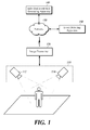
- FIG. 1 is a schematic block diagram of an event detecting system according to at least one embodiment of the present disclosure.
- the event detecting system includes an image capture apparatus 110, an image transmitter 120, a network 130, an individual event rule generating apparatus 140 and an event detecting apparatus 150.
- the image capture apparatus 110 includes a first camera 112 and a second camera 114.
- the image capture apparatus 110 is a device for capturing images.
- the image capture apparatus 110 includes at least one camera, for example, a closed circuit television (CCTV) camera, a security camera, etc. capable of capturing images in order to monitor an object as to whether some events such as movement, intrusion, deviation, theft and being left unattended, are occurred with respect to the object.
- the captured image includes a plurality of frames captured by the multiple cameras 112 and 114.
- the image capture apparatus 110 includes the multiple cameras such as the first camera 112 and the second camera 114 for capturing all or a part of an area of the same location in different directions.
- the first camera 112 is able to be arranged to capture the left side of the playground and the second camera 114 is able to be arranged to capture the right side of the playground.
- the image transmitter 120 transmits the images captured by the image capture apparatus 110 including the multiple cameras to the individual event rule generating apparatus 140 and to the event rule detecting apparatus 150.
- the image transmitter 120 is illustrated as exchanging data of images and rules via the network 130, at least one embodiment of the present disclosure is not limited thereto, and the image transmitter 120 transmits and receives data via a network 130.
- the network 130 is capable of transmitting and receiving the data of the images and rules, and includes least one of local area communication network and a communication network corresponding to a communication base station installed by an operator.
- the individual event rule generating apparatus 140 receives the captured images from the image transmitter 120, generates a main image that is synthesized from the captured images by using predetermined conversion functions, and sets a pre-generated event rule for the main image. In addition, the individual event rule generating apparatus 140 processes the main image causing the event rule through the predetermined conversion function to generate a plurality of individual rule images. And the individual event rule generating apparatus 140 transmits both the event rule for the main image and individual event rules for the individual rule images to the event detecting apparatus 150.
- the individual event rule generating apparatus 140 synthesizes the multiple captured images and generates a single main image through the predetermined conversion functions corresponding to coordinate systems of the cameras.
- the predetermined conversion functions are functions of a scheme such as homography and calibration for correcting a distorted image using coordinates system.
- the individual event rule generating apparatus 140 acquires an event rule for the synthesized main image.
- the event rule serves as a rule that is set up through a manager's manipulation with respect to the synthesized main image and it means conditional information for recognizing the occurrence of an event if there is an object-of-interest moving through a region-of-interest generated through a manager's setting command such as interface manipulation or coordinate input. A detailed description of the event rule will be given with reference to FIG. 2 .
- the individual event rule generating apparatus 140 converts the event rule for the main image into individual event rules corresponding respectively to the multiple cameras through the predetermined conversion functions corresponding to the coordinate systems of the cameras. For example, upon obtaining an event rule set to a circular shape of region-of-interest for the main image, the individual event rule generating apparatus 140 converts the left half circle of the region-of-interest into a first individual event rule through a conversion function corresponding to the first camera 112 and converts the right half circle of the region-of-interest into a second individual event rule through a conversion function corresponding to the second camera 114.
- the individual event rule generating apparatus 140 converts ' ⁇ ' or the left part of the T-shaped region-of-interest to the first individual event rule through the conversion function corresponding to the first camera 112 and converts ' ⁇ ' or the right part of the T-shaped region-of-interest to the second individual event rule through the conversion function corresponding to the second camera 114.
- the event detecting apparatus 150 is adapted to receive the event rule and the individual event rules from the individual event rule generating apparatus 140 and detect an object-of-interest corresponding to an event.
- the event detecting apparatus 150 is connected to the image transmitter 120 to receive the captured images. It receives the event rule and individual event rules from the individual event rule generating apparatus 140.
- the event rule indicates a rule for the main image generated from the individual event rule generating apparatus 140 through a predetermined conversion function and the individual event rules indicate rules corresponding respectively to the cameras, which are converted through predetermined conversion functions corresponding to coordinate systems of the cameras.
- the event detecting apparatus 150 compares prestored background images with the captured images, determines their difference as a moving object-of-interest, and extracts trace information of the object-of-interest.
- the trace information is desirably expressed by a coordinate value, e.g., (x, y) at which the object-of-interest is located, at least one embodiment of the present disclosure is not necessarily restricted thereto.
- the trace information is a distance value from a predetermined starting point.
- the prestored background images are precaptured by multiple cameras and they represent images indicating a still background for a predetermined time rather than the moving object-of-interest in the captured images.
- the event detecting apparatus 150 is responsive to a change in the sign value of the trace information of the object-on-interest for identifying identifies the object-of-interest as an individual event passing through a region-of-interest according to the individual event rules.
- the individual event is an individual event in which the object-of-interest passes through a boundary line in the region-of-interest according to the individual event rules, at least one embodiment of the present disclosure is not necessarily limited thereto, and the individual event rule is an individual event of a trespassing on or an escape from the boundary region in the region-of-interest.
- the event detecting apparatus 150 generates inversely converted trace information by using a predetermined conversion function from the trace information of the object-of-interest determined as the individual event. If multiple pieces of inversely converted trace information corresponding respectively to the multiple cameras comply with the event rule, the event detecting apparatus 150 identifies the inversely converted trace information as a single event. From the trace information of the object-of-interest identified as the individual event, the inversely converted trace information is generated through a conversion function such as homography and calibration for correcting a distorted image by using a coordinate system of a camera.
- a conversion function such as homography and calibration for correcting a distorted image by using a coordinate system of a camera.
- the event detecting apparatus 150 performs the operation of monitoring an event by displaying and/or alerting output information of the detected event.
- the event detecting apparatus 150 calculates statistical information of an event by using the output information for the detected event.
- the statistical information refers to information calculated through determining the number of occurrences of events such as a trespassing on, intrusion into and escape from the region-of-interest.
- FIG. 2 is a schematic block diagram of an individual event rule generator according to at least one embodiment of the present disclosure.
- the individual event rule generating apparatus 140 includes an image receiver 210, an image synthesizer 222, an event rule acquisition unit 224, an individual event rule generator 226, an event rule generator 230 and a rule transmitter 240.
- the image receiver 210 is connected to the image transmitter 120 and receives captured images.
- the captured images refer to images captured by a plurality of cameras included in the image capture apparatus 110.
- a captured image is, but is not always limited to, one frame or is an image composed of a combination of a plurality of frames.
- the image synthesizer 222 generates a single main image by synthesizing the multiple captured images through predetermined conversion functions.
- the image synthesizer 222 synthesizes the multiple captured images by using predetermined conversion functions corresponding to coordinate systems of the cameras to generate the single main image.
- the predetermined conversion functions are functions using a homography and calibration scheme for correcting a distorted image by using the coordinate systems. For example, when the first camera 112 and the second camera 114 capture the images of the same area in different directions, the image synthesizer 222 receives from the first camera 112 a captured image with a pedestrian located in the left side of the image, and receives from the second camera 114 a captured image with the pedestrian located in the right side of the image so as to generate a main image in which the passerby is centrally located through the predetermined conversion function.
- the event rule acquisition unit 224 acquires an event rule for the main image from the event rule generator 230.
- the event rule is a rule that is set up through the manager's manipulation with respect to the synthesized main image from the captured images and it means conditional information for recognizing the occurrence of an event if there is an object-of-interest moving through a region-of-interest generated through a manager's setting command such as interface manipulation or coordinate input.
- the event rule acquisition unit 224 Upon obtaining the event rule for the initially synthesized main image from the image synthesizer 222, the event rule acquisition unit 224 acquires the event rule generated through a manager's setting command such as interface manipulation or coordinate input in the event rule generator 230. In addition, upon obtaining an event rule for the second or later synthesized main image from the image synthesizer 222, the event rule acquisition unit 224 acquires the prestored event rule for the initially synthesized main image in the event rule generator 230.
- the event rule acquisition unit 224 acquires a manager's event rule set on an interface screen in the form of a circular region-of-interest encircling the pedestrian with a predetermined boundary reference value, and it acquires preset event rules for subsequently generated main images. Meanwhile, the event rule acquisition unit 224 acquires an event rule generated through the manager's interface manipulation or coordinate input if the region-of-interest or the boundary reference value of the event rule is changed or deleted.
- event rule acquisition unit 224 has been described as a separate module for acquiring an event rule from the event rule generator 230, at least one embodiment of the present disclosure is not necessarily restricted thereto, to consolidate the event rule acquisition unit 224 and the event rule generator 230 into one module for generating and storing the event rule through interface manipulation or coordinate input by the manager.
- the individual event rule generator 226 converts the event rule for the main image into individual event rules through predetermined conversion functions.
- the individual event rule generator 226 converts the event rule for the main image acquired from the event rule acquisition unit 224 into individual event rules corresponding respectively to the cameras through predetermined conversion functions corresponding to coordinate systems of the cameras. For example, upon acquisition of an event rule set to a circular shape of region-of-interest for the main image from the event rule acquisition unit 224, the individual event rule generator 226 converts the left semi-circle of the region-of-interest into a first individual event rule through a conversion function corresponding to the first camera 112 and convert the right semi-circle of the region-of-interest into a second individual event rule through a conversion function corresponding to the second camera 114.
- the event rule generator 230 generates an event rule for detecting a moving object and transmits the generated event rule to the event rule acquisition unit 224.
- the event rule is a rule set through manipulation by a manager and means conditional information for recognizing the occurrence of an event if there is an object-of-interest moving through a region-of-interest generated through a manager's setting command such as interface manipulation or coordinate input.
- the event rule generator 230 generates an event rule by using a region-of-interest generated through a manager's setting command such as interface manipulation or coordinate input and using a boundary reference value such as a distance value or a sign value set based on the region-of-interest.
- the event rule generator 230 generates the event rule only once through the manager's setting command when the main image is generated initially from the image synthesizer 222 and the event rule generator 230 transmits pre-generated event rule for the second or later synthesized main image to the event rule acquisition unit 224.
- the event rule generator 224 generates a new event rule when the setting command of the manager such as interface manipulation or coordinates input is input due to change or deletion of the region-of-interest or the boundary reference value.
- the event rule generator 230 generates the region-of-interest and the boundary reference value for detecting an event.
- the region-of-interest is a region for detecting an event and refers to a figure including line segments, curves and closed curves.
- the boundary reference value refers to a distance value and a sign value which are set based on the region-of-interest.
- the distance value is set so as to be increased by 1 as the object-of-interest is separated from the boundary of the region-of-interest by a predetermined distance when the boundary of the region-of-interest is set to 0.
- the sign value is a value indicating whether the object-of-interest passes through the region-of-interest. And the sign value is, but is not limited to, '+' and '-'.
- an event for traffic volume of a road is monitored, specifically, when an event for vehicles passing from the left to the right of the region-of-interest is monitored, a sign value of the left side of the region-of-interest is set to '+' and a sign value of the right side of the region-of-interest is set to '-' so that the event for vehicles in which a sign value is changed from '+' to '-' or from '-' to '+' is detected.
- the event rule generator 230 changes an event rule according to characteristics of an event to be monitored through manipulation by a manager. For example, in the case in which the event rule generator 230 sets a region-of-interest through input by the manager and generates an event rule for detecting all events for an object-of-interest passing through the set region-of-interest, when a distance value of the object-of-interest is greater than a predetermined threshold value and a sign value is changed from '+' to '-' or from '-' to '+' based on the preset region-of-interest and the boundary reference value, the event rule generator 230 sets an event rule for determining this as an event.
- the event rule is set such that the case in which the distance value of the object-of-distance is less than the predetermined threshold value is not an event regardless of change of the sign value.
- Such an event rule is set in order to prevent the case in which the object-of-interest approximating to a predetermined distance of the region-of-interest enters or deviates from the region-of-interest from being determined as an event.
- the event rule has been described as detecting the object-of-interests corresponding to an event using both the predetermined distance value and the sign value, at least one embodiment of the present disclosure is not necessarily limited thereto and the event rule detects the event only with the change of the sign value.
- the rule transmitter 240 transmits the event rule for the main image acquired from the event rule acquisition unit 224 and the individual event rules generated from the individual event rule generator 226 to the event detecting apparatus 150 so as to detect an object-of-interest corresponding to an individual event rule and determine whether the detected object-of-interest is an object-of-interest for the same event based on the event rule.
- FIG. 3 is schematic block diagram of an event detecting apparatus according to at least one embodiment of the present disclosure.
- the event detecting apparatus 150 includes a captured image receiver 310, a rule receiver 320, an object-of-interest receiver 330, an individual event determiner 340, an event identifier 350 and a monitoring unit 360.
- the captured image receiver 310 is connected to the image transmitter 120 and receives captured images.
- the captured images are images captured by a plurality of cameras included in the image capture apparatus 110 and represent captured images corresponding respectively to the multiple cameras.
- a captured image is composed of, not necessarily limited thereto, a single captured frame, or the captured image is an image composed of a combination of a plurality of frames.
- the rule receiver 320 receives an event rule and individual event rules from the individual event rule generating apparatus 140.
- the event rule indicates an event rule for a main image generated through a predetermined conversion function in the individual event rule generating apparatus 140 and the individual event rules indicate rules corresponding respectively to the cameras, which are converted from the event rule through predetermined conversion functions corresponding to coordinate systems of the cameras in the individual event rule generating apparatus 140.
- the object-of-interest receiver 330 compares pre-stored background images with the captured images and determines a different part therebetween as a moving object-of-interest, thereby extracting trace information of an object-of-interest.
- the trace information is expressed by a coordinate value (e.g. (x, y)) at which the object-of-interest is located, but not necessarily restricted thereto. And the trace information may be a distance value from a predetermined reference.
- the pre-stored background images are background images captured by the multiple cameras and represent images indicating a still background for a predetermined time rather than the moving object-of-interest in the captured images.
- the trace information of the object-of-interest extracted from the object-of-interest receiver 330 is used for the individual event determiner 340 to determine whether the object-of-interest corresponds to an individual event, based on the individual event rules.
- the individual event determiner 340 determines whether the object-of-interest generated from the individual event determiner 340 corresponds to an individual event, based on the individual event rules. In more detail, the individual event determiner 340 checks whether the sign value of the trace information of the object-of-interest is changed, based on the individual event rules and determines whether the object-of-interest generates an individual event in which the object-of-interest passes through a region-of-interest according to the individual event rules.
- the individual event is an individual event in which the object-of-interest passes through a boundary line of the region-of-interest according to the individual event rules, at least one embodiment of the present disclosure is not necessarily limited thereto, and the individual event is an individual event for intrusion into or deviation from the boundary region of the region-of-interest.
- the region-of-interest for the individual event rule is set to a vertical boundary line in the center of an image and sign values of the left side and the right side of the boundary line based on the vertical boundary line are set to '+' and '-', respectively
- the individual event determiner 340 extracts trace information of a moving object - of-interest from the captured images and identifies an object-of-interest in which the sign value of the trace information is changed from '+' to '-' as the individual event.
- the event identifier 350 generates inversely converted trace information through a predetermined conversion function from the trace information of the object-of-interest identified as the individual event by the individual event determiner 340. If multiple pieces of inversely converted trace information corresponding respectively to the cameras satisfy the event rule, the event identifier 350 identifies the inversely converted trace information as a single event.
- the trace information of the object-of-interest identified as the individual event is converted into the inversely converted trace information through a conversion function such as homography and calibration for correcting a distorted image using a coordinate system of a camera.
- the event identifier 350 For example, if a first object-of-interest determined based on a first individual event rule having a region-of-interest of ' ⁇ ' in the first camera 112 and a second object-of-interest determined based on a second individual event rule having a region-of-interest of ' ⁇ ' in the second camera 114 are determined in the individual event determiner 340, the event identifier 350 generates first inversely converted information through a predetermined conversion function from trace information of the first object-of-interest and generates second inversely converted trace information through a predetermined conversion function from trace information of the second object-of-interest. The event identifier 350 identifies the first inversely converted trace information and the second inversely converted trace information as one event based on an event rule having a region-of-interest of ' ⁇ '.
- the monitoring unit 360 monitors the event by displaying and alerting output information of the event identified from the event identifier 350.
- the monitoring unit 360 is shown in FIG. 3 as being included in the event detecting apparatus 150, at least one embodiment of the present disclosure is not necessarily restricted thereto, and the monitoring unit 360 is implemented by a separate device connected to the event detecting apparatus 150 via local area communication such as a wireless LAN signal, Bluetooth, or ZigBee.
- the monitoring unit 360 calculates statistical information of an event using output information of the detected event.
- the statistical information refers to information calculated through the number of occurrences of events in which the object-of-interest passes through, intrudes into and deviates from the region-of-interest.
- the monitoring unit 360 calculates statistical information of events such as the number of customers visiting a store, traffic volume passing through a road, or the number of people passing through a predetermined area.
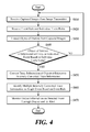
- FIG. 4 is a flowchart of a method performed by an event detecting apparatus for detecting an event, according to at least one embodiment of the present disclosure.
- the event detecting apparatus 150 receives, from the image transmitter 120, images captured from the image capture apparatus 110 (S410).
- the image capture apparatus 110 is implemented as multiple cameras and the event detecting apparatus 150 acquires a plurality of images captured respectively by the multiple cameras.
- the event detecting apparatus 150 receives an event rule and individual event rules from the individual event rule generating apparatus 140 (S420).
- the event rule means an event rule for a main image generated through a predetermined conversion function in the individual event rule generating apparatus 140 and the individual event rules indicate rules corresponding respectively to the multiple cameras, which are converted through predetermined conversion functions corresponding to coordinate systems of the cameras.
- the event detecting apparatus 150 extracts an object-of-interest from the captured images (S430).
- the event detecting apparatus 150 compares pre-stored background images with the captured images and determines a different part therebetween as a moving object-of-interest, thereby extracting trace information of the object-of-interest.
- the trace information is expressed by a coordinate value (e.g. (x, y)) at which the object-of-interest is located, but not restricted thereto.
- the trace information is a distance value from a predetermined reference.
- the pre-stored background images are background images pre-captured by the multiple cameras and represent images indicating a still background for a predetermined time rather than a moving object-of-interest in the captured images.
- the event detecting apparatus 150 determines whether the object-of-interest corresponds to an individual event based on the individual event rules received in Step S420 (S440). The event detecting apparatus 150 determines whether the object-of-interest generates an individual event in which the object-of-interest passes through a region-of-interest by confirming whether a sign value of the trace information of the object-of-interest is changed based on the individual event rules.
- the event detecting apparatus 150 extracts trace information of a moving object-of-interest from the captured images and identify an object-of-interest in which the sign value for the trace information is changed from '+' to '-' as an individual event.
- the event detecting apparatus 150 If the object-of-interest corresponds to the individual event, the event detecting apparatus 150 generates inverse trace information through a predetermined conversion function from the trace information of the object-of-interest (S450).
- the inversely converted trace information is generated by inversely converting the trace information of the object-of-interest corresponding to the individual event through a conversion function such as homography and calibration for correcting a distorted image using a coordinate system of a camera.
- the event detecting apparatus 150 identifies the object-of-interest as a single event (S460). If the inversely converted trace information is included in a region-of-interest based on a preset event rule and if it is determined that a sign value of the inversely converted trace information is changed, the event detecting apparatus 150 identifies the object-of-interest as an event.
- the event detecting apparatus 150 performs monitoring by displaying and alerting output information for the detected event (S470).
- Steps S410 to S470 of FIG. 4 have been described as being sequentially performed, this is only an exemplary description of the technical idea of at least one embodiment of the present disclosure. Those skilled in the art will appreciate that various modifications, additions and substitutions are possible, without departing from the characteristics of at least one embodiment of the present disclosure. For example, the order of steps shown in FIG. 4 are able to be changed, or one or more of Steps S410 to S470 may be performed in parallel. Therefore, the present disclosure is not limited to the time-series order as shown in FIG. 4 .
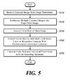
- FIG. 5 is a flowchart of a method performed by an individual event rule generating apparatus for generating an individual event rule according to at least one embodiment of the present disclosure.
- the individual event rule generator 140 receives, from the image transmitter 120, images captured from the image capture apparatus 110 (S510).
- the image capture apparatus 110 includes a plurality of cameras and the individual event rule generator 140 acquires a plurality of captured images captured respectively by the cameras.
- the individual event rule generator 140 synthesizes the captured images into one main image through predetermined conversion functions corresponding to coordinate systems of the cameras (S520).
- the predetermined conversion functions are functions using a homography and calibration scheme for correcting a distorted image using the coordinate system.
- the individual event rule generating apparatus 140 acquires an event rule for the main image (S530).
- the event rule is a rule set through manipulation of a manager for the main image in which the captured images are synthesized and means conditional information for recognizing operation in which an object-of-interest passes through a region-of-interest generated through a setting command of a manager such as interface manipulation or coordinate input as an event.
- the individual event rule generating apparatus 140 converts an event rule for the main image into individual event rules corresponding respectively to the cameras using the predetermined conversion functions corresponding to the coordinate systems of the cameras (S540). For example, if an event rule set as a region-of-interest in the form of a circle in the main image is acquired, the individual event rule generating apparatus 140 converts the left semi-circle of the region-of-interest into a first individual event rule through a conversion function corresponding to the first camera 112 and convert the right semi-circle of the region-of-interest into a second individual event rule through a conversion function corresponding to the second camera 114.
- the individual event rule generating apparatus 140 transmits the event rule for the main image and the individual event rules to the event detecting apparatus 150 in order to detect an object-of-interest corresponding to an event (S550).
- Steps S510 to S550 of FIG. 5 have been described as being sequentially performed, this is only an exemplary description of the technical idea of at least one embodiment of the present disclosure. Those skilled in the art will appreciate that various modifications, additions and substitutions are possible, without departing from the spirit and scope of the claimed invention. For example, the order of steps shown in FIG. 5 is able to be changed, or one or more of Steps S510 to S550 is able to be performed in parallel. Therefore, the present disclosure is not limited to the time-series order as shown in FIG. 5 .
- the present disclosure is highly useful for application to an apparatus and a method for detecting an event from multiple captured images, by converting an event rule for a synthesized image from the multiple captured images through conversion functions corresponding to the coordinate systems of multiple cameras into individual event rules as a basis for determining multiple individual events, and identifying the determined multiple individual events through the predetermined conversion functions as the single event. Therefore, multiple event rules need not be set, repeated events are not detected, and events can be easily stored, identified and managed.
Landscapes
- Engineering & Computer Science (AREA)
- Multimedia (AREA)
- Physics & Mathematics (AREA)
- General Physics & Mathematics (AREA)
- Theoretical Computer Science (AREA)
- Computer Vision & Pattern Recognition (AREA)
- Signal Processing (AREA)
- Closed-Circuit Television Systems (AREA)
- Image Analysis (AREA)
- Studio Devices (AREA)
Abstract
Description
- The present disclosure in one or more embodiments relates to an apparatus and a method for detecting an event from a plurality of captured images. More particularly, the present disclosure relates to an apparatus and a method for detecting a single event from multiple captured images, by converting an event rule for a synthesized image from the multiple captured images through conversion functions corresponding to the coordinate systems of multiple cameras into individual event rules as a basis for determining multiple individual events, and identifying the determined multiple individual events through the predetermined conversion functions as a single event.
- A typical video security system sets an event rule for each of installed cameras and the event rule is used as a basis for detecting each and every event and to produce multiple redundant event detections even from a a single object that actually causes those events. Such unnecessary detections increase processing burden and time required for identifying numerous event occurrences as an actually same event.
- Therefore, the present disclosure according to some embodiments provides an apparatus and a method for detecting a single event from multiple captured images by converting an event rule for a synthesized image from the multiple captured images through conversion functions corresponding to the coordinate systems of the multiple cameras into individual event rules as a basis for determining multiple individual events, and detecting or identifying the determined multiple individual events through the predetermined conversion functions as the single event.
- In accordance with some embodiments of the present disclosure, an apparatus for generating an individual event rule comprises an image receiver, an image synthesis unit, an event rule acquisition unit, an individual event rule generator and a rule transmitter. The image receiver is configured to receive multiple captured images from multiple cameras. The image synthesis unit is configured to synthesize the multiple captured images into a main image through conversion functions corresponding to coordinate systems of the multiple cameras. The event rule acquisition unit is configured to acquire an event rule for the main image. The individual event rule generator is configured to convert the event rule through the conversion functions into individual event rules corresponding respectively to the cameras. The rule transmitter is configured to transmit the individual event rules for identifying a single event.
- In accordance with another embodiment of the present disclosure, an event detecting apparatus includes an image receiver, a rule receiver, an object-of-interest extractor, an individual event determiner, an event identifier and an event output unit. The image receiver is configured to receive multiple captured images from multiple cameras. The rule receiver is configured to receive an event rule as a basis for determining the presence or absence of a predetermined event from a synthesized image of the multiple captured images and individual event rules which are converted from the event rule through conversion functions corresponding to coordinate systems of the multiple cameras. The object-of-interest extractor is configured to extract an object-of-interest from the captured images. The individual event determiner is configured to determine whether trace information of the object-of-interest corresponds to individual events based on the individual event rules. The event identifier is configured to generate inversely converted trace information from the trace information of the object-of-interest through the conversion functions, determine whether multiple pieces of the inversely converted trace information comply with the event rule, and when the multiple pieces of the inversely converted trace information comply with the event rule, identify the object-of-interest as a single event. And the event output unit is configured to generate output information according to the identified single event.
- In accordance with yet another embodiment of the present disclosure, a method for generating an individual event rule, includes receiving multiple captured images from multiple cameras; synthesizing the multiple captured images through conversion functions corresponding to coordinate systems of the multiple cameras into a main image; acquiring an event rule for the main image; generating individual event rules by converting the event rule through the conversion functions into the individual event rules corresponding respectively to the cameras; and transmitting the individual event rules for identifying a single event.
- In accordance with yet another embodiment of the present disclosure, an event detecting method, includes receiving multiple captured images from multiple cameras; receiving an event rule as a basis for determining the presence or absence of a predetermined event of a synthesized image of the multiple captured images and individual event rules which are converted from the event rule through conversion functions corresponding to coordinate systems of the multiple cameras; extracting an object-of-interest from the captured images; determining an individual event by determining whether trace information of the object-of-interest corresponds to individual events based on the individual event rules; performing event identification, including generating an inversely converted trace information from the trace information of the object-of-interest through the conversion functions, determining if multiple pieces of the inversely converted trace information comply with the event rule, and if comply with the event rule, identifying the object-of-interest as a single event; and performing event output by generating output information according to the identified single event.
- According to the present disclosure as described above, a single event is detected from multiple captured images, by converting an event rule for a synthesized image from the multiple captured images through conversion functions corresponding to the coordinate systems of multiple cameras into individual event rules as a basis for determining multiple individual events, and identifying the determined multiple individual events through the predetermined conversion functions as the single event. Therefore, multiple event rules are not necessary, repeated events are not detected, and thus events can be easily stored, identified and managed. In addition, the number of detecting devices can be reduced by setting a single event rule for a plurality of cameras.
-
-
FIG. 1 is a schematic block diagram of an event detecting system according to some embodiments of the present disclosure. -
FIG. 2 is a schematic block diagram of an individual event rule generating apparatus according to some embodiments of the present disclosure. -
FIG. 3 is schematic block diagram of an event detecting apparatus according to some embodiments of the present disclosure. -
FIG. 4 is a flowchart of a method performed by an event detecting apparatus for detecting an event according to some embodiments of the present disclosure. -
FIG. 5 is a flowchart of a method performed by an individual event rule generating apparatus for generating an individual event rule according to some embodiments of the present disclosure. -
- 110: image capture apparatus
- 112: first camera
- 114: second camera
- 120: image transmitter
- 130: network
- 140: individual event rule generating apparatus
- 150: event detecting apparatus
- 210: image receiver
- 222: image synthesizer
- 224: event rule acquisition unit
- 226: individual event rule generator
- 230: event rule generator
- 240: rule transmitter
- 310: captured image receiver
- 320: rule receiver
- 330: object-of-interest extractor
- 340: individual event determiner
- 350: event identifier
- 360: monitoring unit
- Hereinafter, at least one embodiment of the present disclosure will be described in detail with reference to the accompanying drawings. In the following description, like reference numerals designate like elements, although the elements are shown in different drawings. Further, in the following description of the at least one embodiment, a detailed description of known functions and configurations incorporated herein will be omitted for the purpose of clarity and for brevity.
- Additionally, in describing the components of the present disclosure, terms like first, second, A, B, (a), and (b) are used. These are solely for the purpose of differentiating one component from another, and one of ordinary skill would understand that the terms are not to imply or suggest the substances, the order or sequence of the components. If a component is described as 'connected', 'coupled', or 'linked' to another component, one of ordinary skill in the art would understand that the components are not necessarily directly 'connected', 'coupled', or 'linked' but also are indirectly 'connected', 'coupled', or 'linked' via a third component.
-
FIG. 1 is a schematic block diagram of an event detecting system according to at least one embodiment of the present disclosure. - The event detecting system according to at least one embodiment of the present disclosure includes an
image capture apparatus 110, animage transmitter 120, anetwork 130, an individual eventrule generating apparatus 140 and anevent detecting apparatus 150. Theimage capture apparatus 110 includes afirst camera 112 and asecond camera 114. - The
image capture apparatus 110 is a device for capturing images. Theimage capture apparatus 110 according to at least one embodiment of the present disclosure includes at least one camera, for example, a closed circuit television (CCTV) camera, a security camera, etc. capable of capturing images in order to monitor an object as to whether some events such as movement, intrusion, deviation, theft and being left unattended, are occurred with respect to the object. The captured image includes a plurality of frames captured by themultiple cameras - The
image capture apparatus 110 includes the multiple cameras such as thefirst camera 112 and thesecond camera 114 for capturing all or a part of an area of the same location in different directions. For example, when theimage capture apparatus 110 captures a playground, thefirst camera 112 is able to be arranged to capture the left side of the playground and thesecond camera 114 is able to be arranged to capture the right side of the playground. Depending upon the various arrangement of both thefirst camera 112 and thesecond camera 114, there exists an overlapping region between images captured by thecameras - The
image transmitter 120 transmits the images captured by theimage capture apparatus 110 including the multiple cameras to the individual eventrule generating apparatus 140 and to the eventrule detecting apparatus 150. Although theimage transmitter 120 is illustrated as exchanging data of images and rules via thenetwork 130, at least one embodiment of the present disclosure is not limited thereto, and theimage transmitter 120 transmits and receives data via anetwork 130. Herein, thenetwork 130 is capable of transmitting and receiving the data of the images and rules, and includes least one of local area communication network and a communication network corresponding to a communication base station installed by an operator. - The individual event
rule generating apparatus 140 receives the captured images from theimage transmitter 120, generates a main image that is synthesized from the captured images by using predetermined conversion functions, and sets a pre-generated event rule for the main image. In addition, the individual eventrule generating apparatus 140 processes the main image causing the event rule through the predetermined conversion function to generate a plurality of individual rule images. And the individual eventrule generating apparatus 140 transmits both the event rule for the main image and individual event rules for the individual rule images to theevent detecting apparatus 150. - The individual event
rule generating apparatus 140 synthesizes the multiple captured images and generates a single main image through the predetermined conversion functions corresponding to coordinate systems of the cameras. The predetermined conversion functions are functions of a scheme such as homography and calibration for correcting a distorted image using coordinates system. The individual eventrule generating apparatus 140 acquires an event rule for the synthesized main image. The event rule serves as a rule that is set up through a manager's manipulation with respect to the synthesized main image and it means conditional information for recognizing the occurrence of an event if there is an object-of-interest moving through a region-of-interest generated through a manager's setting command such as interface manipulation or coordinate input. A detailed description of the event rule will be given with reference toFIG. 2 . - The individual event
rule generating apparatus 140 converts the event rule for the main image into individual event rules corresponding respectively to the multiple cameras through the predetermined conversion functions corresponding to the coordinate systems of the cameras. For example, upon obtaining an event rule set to a circular shape of region-of-interest for the main image, the individual eventrule generating apparatus 140 converts the left half circle of the region-of-interest into a first individual event rule through a conversion function corresponding to thefirst camera 112 and converts the right half circle of the region-of-interest into a second individual event rule through a conversion function corresponding to thesecond camera 114. For another exemplary main image with an event rule set to '┬' or T-shaped region-of-interest, the individual eventrule generating apparatus 140 converts '┐' or the left part of the T-shaped region-of-interest to the first individual event rule through the conversion function corresponding to thefirst camera 112 and converts '┌ ' or the right part of the T-shaped region-of-interest to the second individual event rule through the conversion function corresponding to thesecond camera 114. - The
event detecting apparatus 150 is adapted to receive the event rule and the individual event rules from the individual eventrule generating apparatus 140 and detect an object-of-interest corresponding to an event. - The
event detecting apparatus 150 according to at least one embodiment of the present disclosure is connected to theimage transmitter 120 to receive the captured images. It receives the event rule and individual event rules from the individual eventrule generating apparatus 140. Here, the event rule indicates a rule for the main image generated from the individual eventrule generating apparatus 140 through a predetermined conversion function and the individual event rules indicate rules corresponding respectively to the cameras, which are converted through predetermined conversion functions corresponding to coordinate systems of the cameras. - The
event detecting apparatus 150 compares prestored background images with the captured images, determines their difference as a moving object-of-interest, and extracts trace information of the object-of-interest. Although the trace information is desirably expressed by a coordinate value, e.g., (x, y) at which the object-of-interest is located, at least one embodiment of the present disclosure is not necessarily restricted thereto. The trace information is a distance value from a predetermined starting point. In addition, the prestored background images are precaptured by multiple cameras and they represent images indicating a still background for a predetermined time rather than the moving object-of-interest in the captured images. - Based on the individual event rules received from the individual event
rule generating apparatus 140, theevent detecting apparatus 150 is responsive to a change in the sign value of the trace information of the object-on-interest for identifying identifies the object-of-interest as an individual event passing through a region-of-interest according to the individual event rules. Although the individual event is an individual event in which the object-of-interest passes through a boundary line in the region-of-interest according to the individual event rules, at least one embodiment of the present disclosure is not necessarily limited thereto, and the individual event rule is an individual event of a trespassing on or an escape from the boundary region in the region-of-interest. - The
event detecting apparatus 150 generates inversely converted trace information by using a predetermined conversion function from the trace information of the object-of-interest determined as the individual event. If multiple pieces of inversely converted trace information corresponding respectively to the multiple cameras comply with the event rule, theevent detecting apparatus 150 identifies the inversely converted trace information as a single event. From the trace information of the object-of-interest identified as the individual event, the inversely converted trace information is generated through a conversion function such as homography and calibration for correcting a distorted image by using a coordinate system of a camera. - The
event detecting apparatus 150 performs the operation of monitoring an event by displaying and/or alerting output information of the detected event. Theevent detecting apparatus 150 calculates statistical information of an event by using the output information for the detected event. The statistical information refers to information calculated through determining the number of occurrences of events such as a trespassing on, intrusion into and escape from the region-of-interest. -
FIG. 2 is a schematic block diagram of an individual event rule generator according to at least one embodiment of the present disclosure. - The individual event
rule generating apparatus 140 according to at least one embodiment of the present disclosure includes animage receiver 210, animage synthesizer 222, an eventrule acquisition unit 224, an individualevent rule generator 226, anevent rule generator 230 and arule transmitter 240. - The
image receiver 210 is connected to theimage transmitter 120 and receives captured images. The captured images refer to images captured by a plurality of cameras included in theimage capture apparatus 110. A captured image is, but is not always limited to, one frame or is an image composed of a combination of a plurality of frames. - The
image synthesizer 222 generates a single main image by synthesizing the multiple captured images through predetermined conversion functions. - The
image synthesizer 222 according to at least one embodiment of the present disclosure synthesizes the multiple captured images by using predetermined conversion functions corresponding to coordinate systems of the cameras to generate the single main image. The predetermined conversion functions are functions using a homography and calibration scheme for correcting a distorted image by using the coordinate systems. For example, when thefirst camera 112 and thesecond camera 114 capture the images of the same area in different directions, theimage synthesizer 222 receives from the first camera 112 a captured image with a pedestrian located in the left side of the image, and receives from the second camera 114 a captured image with the pedestrian located in the right side of the image so as to generate a main image in which the passerby is centrally located through the predetermined conversion function. - The event
rule acquisition unit 224 acquires an event rule for the main image from theevent rule generator 230. The event rule is a rule that is set up through the manager's manipulation with respect to the synthesized main image from the captured images and it means conditional information for recognizing the occurrence of an event if there is an object-of-interest moving through a region-of-interest generated through a manager's setting command such as interface manipulation or coordinate input. - Upon obtaining the event rule for the initially synthesized main image from the
image synthesizer 222, the eventrule acquisition unit 224 acquires the event rule generated through a manager's setting command such as interface manipulation or coordinate input in theevent rule generator 230. In addition, upon obtaining an event rule for the second or later synthesized main image from theimage synthesizer 222, the eventrule acquisition unit 224 acquires the prestored event rule for the initially synthesized main image in theevent rule generator 230. For example, if a main image with a centrally positioned pedestrian is generated first, the eventrule acquisition unit 224 acquires a manager's event rule set on an interface screen in the form of a circular region-of-interest encircling the pedestrian with a predetermined boundary reference value, and it acquires preset event rules for subsequently generated main images. Meanwhile, the eventrule acquisition unit 224 acquires an event rule generated through the manager's interface manipulation or coordinate input if the region-of-interest or the boundary reference value of the event rule is changed or deleted. - Although the event
rule acquisition unit 224 has been described as a separate module for acquiring an event rule from theevent rule generator 230, at least one embodiment of the present disclosure is not necessarily restricted thereto, to consolidate the eventrule acquisition unit 224 and theevent rule generator 230 into one module for generating and storing the event rule through interface manipulation or coordinate input by the manager. - The individual
event rule generator 226 converts the event rule for the main image into individual event rules through predetermined conversion functions. In more detail, the individualevent rule generator 226 converts the event rule for the main image acquired from the eventrule acquisition unit 224 into individual event rules corresponding respectively to the cameras through predetermined conversion functions corresponding to coordinate systems of the cameras. For example, upon acquisition of an event rule set to a circular shape of region-of-interest for the main image from the eventrule acquisition unit 224, the individualevent rule generator 226 converts the left semi-circle of the region-of-interest into a first individual event rule through a conversion function corresponding to thefirst camera 112 and convert the right semi-circle of the region-of-interest into a second individual event rule through a conversion function corresponding to thesecond camera 114. - The
event rule generator 230 generates an event rule for detecting a moving object and transmits the generated event rule to the eventrule acquisition unit 224. The event rule is a rule set through manipulation by a manager and means conditional information for recognizing the occurrence of an event if there is an object-of-interest moving through a region-of-interest generated through a manager's setting command such as interface manipulation or coordinate input. - The
event rule generator 230 according to at least one embodiment of the present disclosure generates an event rule by using a region-of-interest generated through a manager's setting command such as interface manipulation or coordinate input and using a boundary reference value such as a distance value or a sign value set based on the region-of-interest. Theevent rule generator 230 generates the event rule only once through the manager's setting command when the main image is generated initially from theimage synthesizer 222 and theevent rule generator 230 transmits pre-generated event rule for the second or later synthesized main image to the eventrule acquisition unit 224. Theevent rule generator 224 generates a new event rule when the setting command of the manager such as interface manipulation or coordinates input is input due to change or deletion of the region-of-interest or the boundary reference value. - The
event rule generator 230 generates the region-of-interest and the boundary reference value for detecting an event. The region-of-interest is a region for detecting an event and refers to a figure including line segments, curves and closed curves. The boundary reference value refers to a distance value and a sign value which are set based on the region-of-interest. The distance value is set so as to be increased by 1 as the object-of-interest is separated from the boundary of the region-of-interest by a predetermined distance when the boundary of the region-of-interest is set to 0. The sign value is a value indicating whether the object-of-interest passes through the region-of-interest. And the sign value is, but is not limited to, '+' and '-'. For example, when an event for traffic volume of a road is monitored, specifically, when an event for vehicles passing from the left to the right of the region-of-interest is monitored, a sign value of the left side of the region-of-interest is set to '+' and a sign value of the right side of the region-of-interest is set to '-' so that the event for vehicles in which a sign value is changed from '+' to '-' or from '-' to '+' is detected. - The
event rule generator 230 changes an event rule according to characteristics of an event to be monitored through manipulation by a manager. For example, in the case in which theevent rule generator 230 sets a region-of-interest through input by the manager and generates an event rule for detecting all events for an object-of-interest passing through the set region-of-interest, when a distance value of the object-of-interest is greater than a predetermined threshold value and a sign value is changed from '+' to '-' or from '-' to '+' based on the preset region-of-interest and the boundary reference value, theevent rule generator 230 sets an event rule for determining this as an event. - Meanwhile, the event rule is set such that the case in which the distance value of the object-of-distance is less than the predetermined threshold value is not an event regardless of change of the sign value. Such an event rule is set in order to prevent the case in which the object-of-interest approximating to a predetermined distance of the region-of-interest enters or deviates from the region-of-interest from being determined as an event. Although the event rule has been described as detecting the object-of-interests corresponding to an event using both the predetermined distance value and the sign value, at least one embodiment of the present disclosure is not necessarily limited thereto and the event rule detects the event only with the change of the sign value.
- The
rule transmitter 240 transmits the event rule for the main image acquired from the eventrule acquisition unit 224 and the individual event rules generated from the individualevent rule generator 226 to theevent detecting apparatus 150 so as to detect an object-of-interest corresponding to an individual event rule and determine whether the detected object-of-interest is an object-of-interest for the same event based on the event rule. -
FIG. 3 is schematic block diagram of an event detecting apparatus according to at least one embodiment of the present disclosure. - The
event detecting apparatus 150 according to at least one embodiment of the present disclosure includes a capturedimage receiver 310, arule receiver 320, an object-of-interest receiver 330, anindividual event determiner 340, anevent identifier 350 and amonitoring unit 360. - The captured
image receiver 310 is connected to theimage transmitter 120 and receives captured images. The captured images are images captured by a plurality of cameras included in theimage capture apparatus 110 and represent captured images corresponding respectively to the multiple cameras. A captured image is composed of, not necessarily limited thereto, a single captured frame, or the captured image is an image composed of a combination of a plurality of frames. - The
rule receiver 320 receives an event rule and individual event rules from the individual eventrule generating apparatus 140. The event rule indicates an event rule for a main image generated through a predetermined conversion function in the individual eventrule generating apparatus 140 and the individual event rules indicate rules corresponding respectively to the cameras, which are converted from the event rule through predetermined conversion functions corresponding to coordinate systems of the cameras in the individual eventrule generating apparatus 140. - The object-of-
interest receiver 330 compares pre-stored background images with the captured images and determines a different part therebetween as a moving object-of-interest, thereby extracting trace information of an object-of-interest. The trace information is expressed by a coordinate value (e.g. (x, y)) at which the object-of-interest is located, but not necessarily restricted thereto. And the trace information may be a distance value from a predetermined reference. The pre-stored background images are background images captured by the multiple cameras and represent images indicating a still background for a predetermined time rather than the moving object-of-interest in the captured images. The trace information of the object-of-interest extracted from the object-of-interest receiver 330 is used for theindividual event determiner 340 to determine whether the object-of-interest corresponds to an individual event, based on the individual event rules. - The
individual event determiner 340 determines whether the object-of-interest generated from theindividual event determiner 340 corresponds to an individual event, based on the individual event rules. In more detail, theindividual event determiner 340 checks whether the sign value of the trace information of the object-of-interest is changed, based on the individual event rules and determines whether the object-of-interest generates an individual event in which the object-of-interest passes through a region-of-interest according to the individual event rules. Although the individual event is an individual event in which the object-of-interest passes through a boundary line of the region-of-interest according to the individual event rules, at least one embodiment of the present disclosure is not necessarily limited thereto, and the individual event is an individual event for intrusion into or deviation from the boundary region of the region-of-interest. For example, in the case in which the region-of-interest for the individual event rule is set to a vertical boundary line in the center of an image and sign values of the left side and the right side of the boundary line based on the vertical boundary line are set to '+' and '-', respectively, if a rule for an event for recognizing an object-of-interest passing to the right from the left of the boundary line as an individual event, theindividual event determiner 340 extracts trace information of a moving object - of-interest from the captured images and identifies an object-of-interest in which the sign value of the trace information is changed from '+' to '-' as the individual event. - The
event identifier 350 generates inversely converted trace information through a predetermined conversion function from the trace information of the object-of-interest identified as the individual event by theindividual event determiner 340. If multiple pieces of inversely converted trace information corresponding respectively to the cameras satisfy the event rule, theevent identifier 350 identifies the inversely converted trace information as a single event. The trace information of the object-of-interest identified as the individual event is converted into the inversely converted trace information through a conversion function such as homography and calibration for correcting a distorted image using a coordinate system of a camera. - For example, if a first object-of-interest determined based on a first individual event rule having a region-of-interest of '┐' in the
first camera 112 and a second object-of-interest determined based on a second individual event rule having a region-of-interest of '┌' in thesecond camera 114 are determined in theindividual event determiner 340, theevent identifier 350 generates first inversely converted information through a predetermined conversion function from trace information of the first object-of-interest and generates second inversely converted trace information through a predetermined conversion function from trace information of the second object-of-interest. Theevent identifier 350 identifies the first inversely converted trace information and the second inversely converted trace information as one event based on an event rule having a region-of-interest of '┬'. - The
monitoring unit 360 monitors the event by displaying and alerting output information of the event identified from theevent identifier 350. Although themonitoring unit 360 is shown inFIG. 3 as being included in theevent detecting apparatus 150, at least one embodiment of the present disclosure is not necessarily restricted thereto, and themonitoring unit 360 is implemented by a separate device connected to theevent detecting apparatus 150 via local area communication such as a wireless LAN signal, Bluetooth, or ZigBee. - The
monitoring unit 360 calculates statistical information of an event using output information of the detected event. The statistical information refers to information calculated through the number of occurrences of events in which the object-of-interest passes through, intrudes into and deviates from the region-of-interest. For example, themonitoring unit 360 calculates statistical information of events such as the number of customers visiting a store, traffic volume passing through a road, or the number of people passing through a predetermined area. -
FIG. 4 is a flowchart of a method performed by an event detecting apparatus for detecting an event, according to at least one embodiment of the present disclosure. - The
event detecting apparatus 150 receives, from theimage transmitter 120, images captured from the image capture apparatus 110 (S410). Theimage capture apparatus 110 is implemented as multiple cameras and theevent detecting apparatus 150 acquires a plurality of images captured respectively by the multiple cameras. - The
event detecting apparatus 150 receives an event rule and individual event rules from the individual event rule generating apparatus 140 (S420). The event rule means an event rule for a main image generated through a predetermined conversion function in the individual eventrule generating apparatus 140 and the individual event rules indicate rules corresponding respectively to the multiple cameras, which are converted through predetermined conversion functions corresponding to coordinate systems of the cameras. - The
event detecting apparatus 150 extracts an object-of-interest from the captured images (S430). Theevent detecting apparatus 150 compares pre-stored background images with the captured images and determines a different part therebetween as a moving object-of-interest, thereby extracting trace information of the object-of-interest. The trace information is expressed by a coordinate value (e.g. (x, y)) at which the object-of-interest is located, but not restricted thereto. And the trace information is a distance value from a predetermined reference. The pre-stored background images are background images pre-captured by the multiple cameras and represent images indicating a still background for a predetermined time rather than a moving object-of-interest in the captured images. - The
event detecting apparatus 150 determines whether the object-of-interest corresponds to an individual event based on the individual event rules received in Step S420 (S440). Theevent detecting apparatus 150 determines whether the object-of-interest generates an individual event in which the object-of-interest passes through a region-of-interest by confirming whether a sign value of the trace information of the object-of-interest is changed based on the individual event rules. For example, in the case in which a region-of-interest for an individual event rule is set to a vertical boundary line in the center of an image and sign values of the left side and the right side of the boundary line based on the vertical boundary line are set to '+' and '-', respectively, if the individual event rule is a rule for recognizing an object-of-interest passing to the right from the left of the boundary line as the individual event, theevent detecting apparatus 150 extracts trace information of a moving object-of-interest from the captured images and identify an object-of-interest in which the sign value for the trace information is changed from '+' to '-' as an individual event. - If the object-of-interest corresponds to the individual event, the
event detecting apparatus 150 generates inverse trace information through a predetermined conversion function from the trace information of the object-of-interest (S450). The inversely converted trace information is generated by inversely converting the trace information of the object-of-interest corresponding to the individual event through a conversion function such as homography and calibration for correcting a distorted image using a coordinate system of a camera. - If multiple pieces of inversely converted trace information comply with the event rule received in Step S420, the
event detecting apparatus 150 identifies the object-of-interest as a single event (S460). If the inversely converted trace information is included in a region-of-interest based on a preset event rule and if it is determined that a sign value of the inversely converted trace information is changed, theevent detecting apparatus 150 identifies the object-of-interest as an event. - The
event detecting apparatus 150 performs monitoring by displaying and alerting output information for the detected event (S470). - Although Steps S410 to S470 of
FIG. 4 have been described as being sequentially performed, this is only an exemplary description of the technical idea of at least one embodiment of the present disclosure. Those skilled in the art will appreciate that various modifications, additions and substitutions are possible, without departing from the characteristics of at least one embodiment of the present disclosure. For example, the order of steps shown inFIG. 4 are able to be changed, or one or more of Steps S410 to S470 may be performed in parallel. Therefore, the present disclosure is not limited to the time-series order as shown inFIG. 4 . -
FIG. 5 is a flowchart of a method performed by an individual event rule generating apparatus for generating an individual event rule according to at least one embodiment of the present disclosure. - The individual
event rule generator 140 receives, from theimage transmitter 120, images captured from the image capture apparatus 110 (S510). Theimage capture apparatus 110 includes a plurality of cameras and the individualevent rule generator 140 acquires a plurality of captured images captured respectively by the cameras. - The individual
event rule generator 140 synthesizes the captured images into one main image through predetermined conversion functions corresponding to coordinate systems of the cameras (S520). The predetermined conversion functions are functions using a homography and calibration scheme for correcting a distorted image using the coordinate system. - The individual event
rule generating apparatus 140 acquires an event rule for the main image (S530). The event rule is a rule set through manipulation of a manager for the main image in which the captured images are synthesized and means conditional information for recognizing operation in which an object-of-interest passes through a region-of-interest generated through a setting command of a manager such as interface manipulation or coordinate input as an event. - The individual event
rule generating apparatus 140 converts an event rule for the main image into individual event rules corresponding respectively to the cameras using the predetermined conversion functions corresponding to the coordinate systems of the cameras (S540). For example, if an event rule set as a region-of-interest in the form of a circle in the main image is acquired, the individual eventrule generating apparatus 140 converts the left semi-circle of the region-of-interest into a first individual event rule through a conversion function corresponding to thefirst camera 112 and convert the right semi-circle of the region-of-interest into a second individual event rule through a conversion function corresponding to thesecond camera 114. - The individual event
rule generating apparatus 140 transmits the event rule for the main image and the individual event rules to theevent detecting apparatus 150 in order to detect an object-of-interest corresponding to an event (S550). - Although Steps S510 to S550 of
FIG. 5 have been described as being sequentially performed, this is only an exemplary description of the technical idea of at least one embodiment of the present disclosure. Those skilled in the art will appreciate that various modifications, additions and substitutions are possible, without departing from the spirit and scope of the claimed invention. For example, the order of steps shown inFIG. 5 is able to be changed, or one or more of Steps S510 to S550 is able to be performed in parallel. Therefore, the present disclosure is not limited to the time-series order as shown inFIG. 5 . - Although exemplary embodiments of the present disclosure have been described for illustrative purposes, those skilled in the art will appreciate that various modifications, additions and substitutions are possible, without departing from the spirit and scope of the claimed invention. Therefore, exemplary embodiments of the present disclosure have been described for the sake of brevity and clarity. Accordingly, one of ordinary skill would understand that the scope of the disclosure is not limited by the explicitly described above embodiments but by the claims and equivalents thereof.
- As described above, the present disclosure is highly useful for application to an apparatus and a method for detecting an event from multiple captured images, by converting an event rule for a synthesized image from the multiple captured images through conversion functions corresponding to the coordinate systems of multiple cameras into individual event rules as a basis for determining multiple individual events, and identifying the determined multiple individual events through the predetermined conversion functions as the single event. Therefore, multiple event rules need not be set, repeated events are not detected, and events can be easily stored, identified and managed.
- If applicable, this application claims priority under 35 U.S.C §119(a) of Patent Application No.
10-2012-0106797, filed on September 25, 2012
Claims (13)
- An apparatus for generating an individual event rule, the apparatus comprising:an image receiver configured to receive multiple captured images from multiple cameras;an image synthesis unit configured to synthesize the multiple captured images into a main image through conversion functions corresponding to coordinate systems of the multiple cameras;an event rule acquisition unit configured to acquire an event rule for the main image;an individual event rule generator configured to convert the event rule through the conversion functions into individual event rules corresponding respectively to the cameras; anda rule transmitter configured to transmit the individual event rules for identifying a single event.
- The apparatus of claim 1, wherein the event rule acquisition unit is configured to
generate a predetermined figure for the main image as a region-of-interest, and
acquire the event rule by using a distance value and a sign value set based on the region-of-interest. - The apparatus of claim 2, wherein the event rule is conditional information for identifying an object-of-interest as the event passing through the region-of-interest when a distance value of the object-of-interest is greater than a threshold value and a sign value is changed as a result of confirming a location of the object-of-interest.
- The apparatus of claim 1, wherein the image synthesis unit is configured to generate the main image through the conversion functions using at least one of homography and calibration.
- The apparatus of claim 1, wherein the individual event rule generator is configured to generate the individual event rules by converting the event rule, each individual event rule having a predetermined distinction for the corresponding camera.
- The apparatus of claim 1, wherein
the rule transmitter is configured to transmit the individual event rules to an event detecting apparatus, and
the event detecting apparatus is configured to
determine an object-of-interest corresponding to an individual event, generate inversely converted trace information of the object-of-interest, and
identify the object-of-interest as an event when the inversely converted trace information corresponds to the event rule. - The apparatus of claim 1, wherein the captured images are images captured by the multiple cameras for capturing all or a part of an area at the same location from predetermined different directions.
- An event detecting apparatus, comprising:an image receiver configured to receive multiple captured images from multiple cameras;a rule receiver configured to receive
an event rule as a basis for determining the presence or absence of a predetermined event from a synthesized image of the multiple captured images, and
individual event rules which are converted from the event rule through conversion functions corresponding to coordinate systems of the multiple cameras;an object-of-interest extractor configured to extract an object-of-interest from the captured images;an individual event determiner configured to determine whether trace information of the object-of-interest corresponds to individual events based on the individual event rules;an event identifier configured to
generate inversely converted trace information from the trace information of the object-of-interest through the conversion functions,
determine whether multiple pieces of the inversely converted trace information comply with the event rule, and
when the multiple pieces of the inversely converted trace information comply with the event rule, identify the object-of-interest as a single event; andan event output unit configured to generate output information according to the identified single event. - The event detecting apparatus of claim 8, wherein the object-of-interest extractor is configured to extract the object-of-interest by comparing background images pre-captured from the multiple cameras with the captured images.
- The event detecting apparatus of claim 8, wherein
the individual event determiner is configured to detect the object-of-interest using the individual event rules converted from the event rule, each individual event rule having a predetermined distinction for the corresponding camera, and
the event identifier is configured to identify the object-of-interest as an individual event when a sign value of the trace information is changed. - The event detecting apparatus of claim 8, wherein the event identifier is configured to identify the object-of-interest as an event passing through a predetermined region-of-interest when a sign value of the inversely converted trace information is changed based on the event rule in which the predetermined region-of-interest and a sign value are set.
- A method for generating an individual event rule, the method comprising:receiving multiple captured images from multiple cameras;synthesizing the multiple captured images into a main image through conversion functions corresponding to coordinate systems of the multiple cameras;acquiring an event rule for the main image;generating individual event rules by converting the event rule through the conversion functions into the individual event rules corresponding respectively to the cameras; andtransmitting the individual event rules for identifying a single event.
- An event detecting method, comprising:receiving multiple captured images from multiple cameras;receiving
an event rule as a basis for determining the presence or absence of a predetermined event from a synthesized image of the multiple captured images, and
individual event rules which are converted from the event rule through conversion functions corresponding to coordinate systems of the multiple cameras;extracting an object-of-interest from the captured images;determining an individual event by determining whether trace information of the object-of-interest corresponds to individual events based on the individual event rules;performing event identification, comprising:generating an inversely converted trace information from the trace information of the object-of-interest through the conversion functions,determining whether multiple pieces of the inversely converted trace information comply with the event rule, andwhen the multiple pieces of the inversely converted trace information comply with the event rule, identifying the object-of-interest as a single event; andperforming event output by generating output information according to the identified single event.
Applications Claiming Priority (2)
| Application Number | Priority Date | Filing Date | Title |
|---|---|---|---|
| KR1020120106797A KR101937272B1 (en) | 2012-09-25 | 2012-09-25 | Method and Apparatus for Detecting Event from Multiple Image |
| PCT/KR2013/008592 WO2014051337A1 (en) | 2012-09-25 | 2013-09-25 | Apparatus and method for detecting event from plurality of photographed images |
Publications (3)
| Publication Number | Publication Date |
|---|---|
| EP2903261A1 true EP2903261A1 (en) | 2015-08-05 |
| EP2903261A4 EP2903261A4 (en) | 2016-10-26 |
| EP2903261B1 EP2903261B1 (en) | 2020-11-25 |
Family
ID=50388638
Family Applications (1)
| Application Number | Title | Priority Date | Filing Date |
|---|---|---|---|
| EP13840942.0A Active EP2903261B1 (en) | 2012-09-25 | 2013-09-25 | Apparatus and method for detecting event from plurality of photographed images |
Country Status (5)
| Country | Link |
|---|---|
| US (1) | US9639937B2 (en) |
| EP (1) | EP2903261B1 (en) |
| KR (1) | KR101937272B1 (en) |
| CN (1) | CN104704816B (en) |
| WO (1) | WO2014051337A1 (en) |
Cited By (1)
| Publication number | Priority date | Publication date | Assignee | Title |
|---|---|---|---|---|
| EP3310044A1 (en) * | 2016-10-14 | 2018-04-18 | Synology Incorporated | Method and associated apparatus for performing cooperative counting with aid of multiple cameras |
Families Citing this family (14)
| Publication number | Priority date | Publication date | Assignee | Title |
|---|---|---|---|---|
| WO2014051262A1 (en) * | 2012-09-25 | 2014-04-03 | 에스케이텔레콤 주식회사 | Method for setting event rules and event monitoring apparatus using same |
| KR101632198B1 (en) * | 2015-02-10 | 2016-07-01 | 주식회사 일리시스 | Method for detecting events occurring in regions of interest based on object transit time |
| EP3159853B1 (en) * | 2015-10-23 | 2019-03-27 | Harman International Industries, Incorporated | Systems and methods for advanced driver assistance analytics |
| US10592749B2 (en) * | 2016-11-14 | 2020-03-17 | General Electric Company | Systems and methods for analyzing turns at an airport |
| KR102634188B1 (en) | 2016-11-30 | 2024-02-05 | 한화비전 주식회사 | System for monitoring image |
| JP6844503B2 (en) * | 2017-11-06 | 2021-03-17 | 京セラドキュメントソリューションズ株式会社 | Monitoring system |
| CN109974667B (en) * | 2017-12-27 | 2021-07-23 | 宁波方太厨具有限公司 | Indoor human body positioning method |
| JP6915575B2 (en) * | 2018-03-29 | 2021-08-04 | 京セラドキュメントソリューションズ株式会社 | Control device and monitoring system |
| CN109872483B (en) * | 2019-02-22 | 2020-09-29 | 华中光电技术研究所(中国船舶重工集团有限公司第七一七研究所) | Intrusion alert photoelectric monitoring system and method |
| KR102247359B1 (en) * | 2019-07-31 | 2021-05-04 | (주)유디피 | Image analysis system and method for remote monitoring |
| CN113099173A (en) * | 2021-03-25 | 2021-07-09 | 湖南桥康智能科技有限公司 | Intelligent network camera with object displacement measurement and calculation functions |
| CN112797900B (en) * | 2021-04-07 | 2021-07-06 | 中科慧远视觉技术(北京)有限公司 | Multi-camera plate size measuring method |
| EP4106328B1 (en) * | 2021-06-17 | 2025-10-08 | Honeywell International Inc. | Video surveillance system with distributed intelligence |
| CN114170752A (en) * | 2021-12-08 | 2022-03-11 | 潍坊欣龙生物材料有限公司 | Monitoring method for perimeter security |
Family Cites Families (20)
| Publication number | Priority date | Publication date | Assignee | Title |
|---|---|---|---|---|
| JP2001523900A (en) | 1997-07-15 | 2001-11-27 | シルバーブルック リサーチ ピーティーワイ リミテッド | Camera with internal printing system |
| US8564661B2 (en) * | 2000-10-24 | 2013-10-22 | Objectvideo, Inc. | Video analytic rule detection system and method |
| KR100940237B1 (en) * | 2003-03-06 | 2010-02-04 | 삼성테크윈 주식회사 | Surveillance system capable of monitoring and recording control in conjunction with event occurrence and its control method |
| EP1771811A4 (en) * | 2004-07-26 | 2010-06-09 | Silicon Optix Inc | Panoramic vision system and method |
| KR100872878B1 (en) * | 2006-09-29 | 2008-12-10 | (주)로그시스 | Event detection system of surveillance camera |
| KR101187908B1 (en) * | 2007-09-11 | 2012-10-05 | 삼성테크윈 주식회사 | Integrated surveillance system diplaying a plural of event images and method using the same |
| CN101119482B (en) * | 2007-09-28 | 2011-07-20 | 北京智安邦科技有限公司 | Overall view monitoring method and apparatus |
| KR20090035379A (en) * | 2007-10-05 | 2009-04-09 | 주식회사 케이티 | Intelligent Security Security System and its Control Method Using Video Detection in Parking Lot |
| KR100924580B1 (en) * | 2007-12-26 | 2009-10-30 | (주)네스테크놀로지 | Integrated video surveillance system for signal converter for video signal monitoring |
| US20090195382A1 (en) * | 2008-01-31 | 2009-08-06 | Sensormatic Electronics Corporation | Video sensor and alarm system and method with object and event classification |
| KR100954375B1 (en) * | 2008-05-06 | 2010-04-26 | (주) 티앤엑스시스템즈 | Intelligent video surveillance system |
| US8570376B1 (en) * | 2008-11-19 | 2013-10-29 | Videomining Corporation | Method and system for efficient sampling of videos using spatiotemporal constraints for statistical behavior analysis |
| US8416296B2 (en) * | 2009-04-14 | 2013-04-09 | Behavioral Recognition Systems, Inc. | Mapper component for multiple art networks in a video analysis system |
| US8503539B2 (en) * | 2010-02-26 | 2013-08-06 | Bao Tran | High definition personal computer (PC) cam |
| KR20110136907A (en) * | 2010-06-16 | 2011-12-22 | 주식회사 영국전자 | Wide area monitoring system and monitoring data processing method therefor |
| KR101180887B1 (en) * | 2010-09-08 | 2012-09-07 | 중앙대학교 산학협력단 | Apparatus and method for detecting abnormal behavior |
| CN102045544A (en) * | 2010-11-10 | 2011-05-04 | 无锡中星微电子有限公司 | Video monitoring system and video data transmission method thereof |
| CN102510482A (en) * | 2011-11-29 | 2012-06-20 | 蔡棽 | Image splicing reconstruction and overall monitoring method for improving visibility and visual distance |
| US9338409B2 (en) * | 2012-01-17 | 2016-05-10 | Avigilon Fortress Corporation | System and method for home health care monitoring |
| JP6148480B2 (en) * | 2012-04-06 | 2017-06-14 | キヤノン株式会社 | Image processing apparatus and image processing method |
-
2012
- 2012-09-25 KR KR1020120106797A patent/KR101937272B1/en active Active
-
2013
- 2013-09-25 WO PCT/KR2013/008592 patent/WO2014051337A1/en not_active Ceased
- 2013-09-25 CN CN201380049910.2A patent/CN104704816B/en active Active
- 2013-09-25 EP EP13840942.0A patent/EP2903261B1/en active Active
-
2015
- 2015-03-24 US US14/667,552 patent/US9639937B2/en active Active
Cited By (2)
| Publication number | Priority date | Publication date | Assignee | Title |
|---|---|---|---|---|
| EP3310044A1 (en) * | 2016-10-14 | 2018-04-18 | Synology Incorporated | Method and associated apparatus for performing cooperative counting with aid of multiple cameras |
| US10223592B2 (en) | 2016-10-14 | 2019-03-05 | Synology Incorporated | Method and associated apparatus for performing cooperative counting with aid of multiple cameras |
Also Published As
| Publication number | Publication date |
|---|---|
| EP2903261B1 (en) | 2020-11-25 |
| US20150199815A1 (en) | 2015-07-16 |
| KR101937272B1 (en) | 2019-04-09 |
| KR20140039927A (en) | 2014-04-02 |
| EP2903261A4 (en) | 2016-10-26 |
| US9639937B2 (en) | 2017-05-02 |
| WO2014051337A1 (en) | 2014-04-03 |
| CN104704816A (en) | 2015-06-10 |
| CN104704816B (en) | 2018-06-01 |
Similar Documents
| Publication | Publication Date | Title |
|---|---|---|
| US9639937B2 (en) | Apparatus and method for detecting event from plurality of photographed images | |
| JP6644827B2 (en) | Video surveillance system and video surveillance method | |
| KR101793636B1 (en) | Image processing system | |
| KR102045871B1 (en) | System For Detecting Fire Based on Artificial Intelligence And Method For Detecting Fire Based on Artificial Intelligence | |
| KR101570339B1 (en) | The predicting system for anti-crime through analyzing server of images | |
| EP2966852B1 (en) | Video monitoring method, device and system | |
| KR101471846B1 (en) | The FX controlling box and FX protecting system and its controlling way of FX system | |
| KR101513215B1 (en) | The analyzing server of CCTV images among behavior patterns of objects | |
| KR101397453B1 (en) | System for monitoring an image and method thereof | |
| US20130188031A1 (en) | Risk recognition method for use in video surveillance system based on human identification | |
| KR101921868B1 (en) | Intelligent video mornitoring system and method thereof | |
| KR101352337B1 (en) | Intelligent type of apparatus for monitering a zone with a plural functions and method for the same | |
| KR102247359B1 (en) | Image analysis system and method for remote monitoring | |
| KR101262355B1 (en) | Video serveillance method and server performing the same | |
| JP2007158421A (en) | Surveillance camera system and face image tracking recording method | |
| KR101485512B1 (en) | The sequence processing method of images through hippocampal neual network learning of behavior patterns in case of future crimes | |
| KR101298684B1 (en) | Non sensor based vehicle number recognition system and operating method thereof | |
| KR20040105612A (en) | Change detecting method and apparatus and monitoring system using the method or apparatus | |
| KR20160053601A (en) | Appratus and method for processing image | |
| KR101492473B1 (en) | Context-aware cctv intergrated managment system with user-based | |
| KR20110109147A (en) | Security system | |
| KR101621822B1 (en) | Device for security and recognizing number of license plate based on hybrid image transmission, and method for recognizing and providing number of license plate using the same | |
| KR20150112712A (en) | The analyzing server of cctv images among behavior patterns of objects | |
| KR102056854B1 (en) | Internet protocol video wall system and method of driving the same | |
| KR102113527B1 (en) | Thermal ip cctv system and method for detecting fire by using the same |
Legal Events
| Date | Code | Title | Description |
|---|---|---|---|
| PUAI | Public reference made under article 153(3) epc to a published international application that has entered the european phase |
Free format text: ORIGINAL CODE: 0009012 |
|
| 17P | Request for examination filed |
Effective date: 20150427 |
|
| AK | Designated contracting states |
Kind code of ref document: A1 Designated state(s): AL AT BE BG CH CY CZ DE DK EE ES FI FR GB GR HR HU IE IS IT LI LT LU LV MC MK MT NL NO PL PT RO RS SE SI SK SM TR |
|
| AX | Request for extension of the european patent |
Extension state: BA ME |
|
| DAX | Request for extension of the european patent (deleted) | ||
| RA4 | Supplementary search report drawn up and despatched (corrected) |
Effective date: 20160927 |
|
| RIC1 | Information provided on ipc code assigned before grant |
Ipc: H04N 7/18 20060101AFI20160920BHEP Ipc: G06T 7/20 20060101ALI20160920BHEP Ipc: G06K 9/00 20060101ALI20160920BHEP |
|
| STAA | Information on the status of an ep patent application or granted ep patent |
Free format text: STATUS: EXAMINATION IS IN PROGRESS |
|
| 17Q | First examination report despatched |
Effective date: 20180723 |
|
| GRAP | Despatch of communication of intention to grant a patent |
Free format text: ORIGINAL CODE: EPIDOSNIGR1 |
|
| STAA | Information on the status of an ep patent application or granted ep patent |
Free format text: STATUS: GRANT OF PATENT IS INTENDED |
|
| INTG | Intention to grant announced |
Effective date: 20200619 |
|
| GRAS | Grant fee paid |
Free format text: ORIGINAL CODE: EPIDOSNIGR3 |
|
| GRAA | (expected) grant |
Free format text: ORIGINAL CODE: 0009210 |
|
| STAA | Information on the status of an ep patent application or granted ep patent |
Free format text: STATUS: THE PATENT HAS BEEN GRANTED |
|
| AK | Designated contracting states |
Kind code of ref document: B1 Designated state(s): AL AT BE BG CH CY CZ DE DK EE ES FI FR GB GR HR HU IE IS IT LI LT LU LV MC MK MT NL NO PL PT RO RS SE SI SK SM TR |
|
| REG | Reference to a national code |
Ref country code: GB Ref legal event code: FG4D |
|
| REG | Reference to a national code |
Ref country code: CH Ref legal event code: EP |
|
| REG | Reference to a national code |
Ref country code: AT Ref legal event code: REF Ref document number: 1339640 Country of ref document: AT Kind code of ref document: T Effective date: 20201215 |
|
| REG | Reference to a national code |
Ref country code: DE Ref legal event code: R096 Ref document number: 602013074357 Country of ref document: DE |
|
| REG | Reference to a national code |
Ref country code: IE Ref legal event code: FG4D |
|
| REG | Reference to a national code |
Ref country code: AT Ref legal event code: MK05 Ref document number: 1339640 Country of ref document: AT Kind code of ref document: T Effective date: 20201125 |
|
| REG | Reference to a national code |
Ref country code: NL Ref legal event code: MP Effective date: 20201125 |
|
| PG25 | Lapsed in a contracting state [announced via postgrant information from national office to epo] |
Ref country code: GR Free format text: LAPSE BECAUSE OF FAILURE TO SUBMIT A TRANSLATION OF THE DESCRIPTION OR TO PAY THE FEE WITHIN THE PRESCRIBED TIME-LIMIT Effective date: 20210226 Ref country code: FI Free format text: LAPSE BECAUSE OF FAILURE TO SUBMIT A TRANSLATION OF THE DESCRIPTION OR TO PAY THE FEE WITHIN THE PRESCRIBED TIME-LIMIT Effective date: 20201125 Ref country code: RS Free format text: LAPSE BECAUSE OF FAILURE TO SUBMIT A TRANSLATION OF THE DESCRIPTION OR TO PAY THE FEE WITHIN THE PRESCRIBED TIME-LIMIT Effective date: 20201125 Ref country code: NO Free format text: LAPSE BECAUSE OF FAILURE TO SUBMIT A TRANSLATION OF THE DESCRIPTION OR TO PAY THE FEE WITHIN THE PRESCRIBED TIME-LIMIT Effective date: 20210225 Ref country code: PT Free format text: LAPSE BECAUSE OF FAILURE TO SUBMIT A TRANSLATION OF THE DESCRIPTION OR TO PAY THE FEE WITHIN THE PRESCRIBED TIME-LIMIT Effective date: 20210325 |
|
| PG25 | Lapsed in a contracting state [announced via postgrant information from national office to epo] |
Ref country code: LV Free format text: LAPSE BECAUSE OF FAILURE TO SUBMIT A TRANSLATION OF THE DESCRIPTION OR TO PAY THE FEE WITHIN THE PRESCRIBED TIME-LIMIT Effective date: 20201125 Ref country code: IS Free format text: LAPSE BECAUSE OF FAILURE TO SUBMIT A TRANSLATION OF THE DESCRIPTION OR TO PAY THE FEE WITHIN THE PRESCRIBED TIME-LIMIT Effective date: 20210325 Ref country code: PL Free format text: LAPSE BECAUSE OF FAILURE TO SUBMIT A TRANSLATION OF THE DESCRIPTION OR TO PAY THE FEE WITHIN THE PRESCRIBED TIME-LIMIT Effective date: 20201125 Ref country code: SE Free format text: LAPSE BECAUSE OF FAILURE TO SUBMIT A TRANSLATION OF THE DESCRIPTION OR TO PAY THE FEE WITHIN THE PRESCRIBED TIME-LIMIT Effective date: 20201125 Ref country code: BG Free format text: LAPSE BECAUSE OF FAILURE TO SUBMIT A TRANSLATION OF THE DESCRIPTION OR TO PAY THE FEE WITHIN THE PRESCRIBED TIME-LIMIT Effective date: 20210225 Ref country code: AT Free format text: LAPSE BECAUSE OF FAILURE TO SUBMIT A TRANSLATION OF THE DESCRIPTION OR TO PAY THE FEE WITHIN THE PRESCRIBED TIME-LIMIT Effective date: 20201125 |
|
| REG | Reference to a national code |
Ref country code: LT Ref legal event code: MG9D |
|
| PG25 | Lapsed in a contracting state [announced via postgrant information from national office to epo] |
Ref country code: HR Free format text: LAPSE BECAUSE OF FAILURE TO SUBMIT A TRANSLATION OF THE DESCRIPTION OR TO PAY THE FEE WITHIN THE PRESCRIBED TIME-LIMIT Effective date: 20201125 |
|
| PG25 | Lapsed in a contracting state [announced via postgrant information from national office to epo] |
Ref country code: LT Free format text: LAPSE BECAUSE OF FAILURE TO SUBMIT A TRANSLATION OF THE DESCRIPTION OR TO PAY THE FEE WITHIN THE PRESCRIBED TIME-LIMIT Effective date: 20201125 Ref country code: RO Free format text: LAPSE BECAUSE OF FAILURE TO SUBMIT A TRANSLATION OF THE DESCRIPTION OR TO PAY THE FEE WITHIN THE PRESCRIBED TIME-LIMIT Effective date: 20201125 Ref country code: SK Free format text: LAPSE BECAUSE OF FAILURE TO SUBMIT A TRANSLATION OF THE DESCRIPTION OR TO PAY THE FEE WITHIN THE PRESCRIBED TIME-LIMIT Effective date: 20201125 Ref country code: SM Free format text: LAPSE BECAUSE OF FAILURE TO SUBMIT A TRANSLATION OF THE DESCRIPTION OR TO PAY THE FEE WITHIN THE PRESCRIBED TIME-LIMIT Effective date: 20201125 Ref country code: EE Free format text: LAPSE BECAUSE OF FAILURE TO SUBMIT A TRANSLATION OF THE DESCRIPTION OR TO PAY THE FEE WITHIN THE PRESCRIBED TIME-LIMIT Effective date: 20201125 Ref country code: CZ Free format text: LAPSE BECAUSE OF FAILURE TO SUBMIT A TRANSLATION OF THE DESCRIPTION OR TO PAY THE FEE WITHIN THE PRESCRIBED TIME-LIMIT Effective date: 20201125 |
|
| REG | Reference to a national code |
Ref country code: DE Ref legal event code: R097 Ref document number: 602013074357 Country of ref document: DE |
|
| PG25 | Lapsed in a contracting state [announced via postgrant information from national office to epo] |
Ref country code: DK Free format text: LAPSE BECAUSE OF FAILURE TO SUBMIT A TRANSLATION OF THE DESCRIPTION OR TO PAY THE FEE WITHIN THE PRESCRIBED TIME-LIMIT Effective date: 20201125 |
|
| PLBE | No opposition filed within time limit |
Free format text: ORIGINAL CODE: 0009261 |
|
| STAA | Information on the status of an ep patent application or granted ep patent |
Free format text: STATUS: NO OPPOSITION FILED WITHIN TIME LIMIT |
|
| PG25 | Lapsed in a contracting state [announced via postgrant information from national office to epo] |
Ref country code: NL Free format text: LAPSE BECAUSE OF FAILURE TO SUBMIT A TRANSLATION OF THE DESCRIPTION OR TO PAY THE FEE WITHIN THE PRESCRIBED TIME-LIMIT Effective date: 20201125 Ref country code: AL Free format text: LAPSE BECAUSE OF FAILURE TO SUBMIT A TRANSLATION OF THE DESCRIPTION OR TO PAY THE FEE WITHIN THE PRESCRIBED TIME-LIMIT Effective date: 20201125 Ref country code: IT Free format text: LAPSE BECAUSE OF FAILURE TO SUBMIT A TRANSLATION OF THE DESCRIPTION OR TO PAY THE FEE WITHIN THE PRESCRIBED TIME-LIMIT Effective date: 20201125 |
|
| 26N | No opposition filed |
Effective date: 20210826 |
|
| PG25 | Lapsed in a contracting state [announced via postgrant information from national office to epo] |
Ref country code: SI Free format text: LAPSE BECAUSE OF FAILURE TO SUBMIT A TRANSLATION OF THE DESCRIPTION OR TO PAY THE FEE WITHIN THE PRESCRIBED TIME-LIMIT Effective date: 20201125 Ref country code: ES Free format text: LAPSE BECAUSE OF FAILURE TO SUBMIT A TRANSLATION OF THE DESCRIPTION OR TO PAY THE FEE WITHIN THE PRESCRIBED TIME-LIMIT Effective date: 20201125 |
|
| REG | Reference to a national code |
Ref country code: CH Ref legal event code: PL |
|
| REG | Reference to a national code |
Ref country code: BE Ref legal event code: MM Effective date: 20210930 |
|
| PG25 | Lapsed in a contracting state [announced via postgrant information from national office to epo] |
Ref country code: IS Free format text: LAPSE BECAUSE OF FAILURE TO SUBMIT A TRANSLATION OF THE DESCRIPTION OR TO PAY THE FEE WITHIN THE PRESCRIBED TIME-LIMIT Effective date: 20210325 Ref country code: MC Free format text: LAPSE BECAUSE OF FAILURE TO SUBMIT A TRANSLATION OF THE DESCRIPTION OR TO PAY THE FEE WITHIN THE PRESCRIBED TIME-LIMIT Effective date: 20201125 |
|
| PG25 | Lapsed in a contracting state [announced via postgrant information from national office to epo] |
Ref country code: LU Free format text: LAPSE BECAUSE OF NON-PAYMENT OF DUE FEES Effective date: 20210925 Ref country code: IE Free format text: LAPSE BECAUSE OF NON-PAYMENT OF DUE FEES Effective date: 20210925 Ref country code: FR Free format text: LAPSE BECAUSE OF NON-PAYMENT OF DUE FEES Effective date: 20210930 Ref country code: BE Free format text: LAPSE BECAUSE OF NON-PAYMENT OF DUE FEES Effective date: 20210930 |
|
| PG25 | Lapsed in a contracting state [announced via postgrant information from national office to epo] |
Ref country code: LI Free format text: LAPSE BECAUSE OF NON-PAYMENT OF DUE FEES Effective date: 20210930 Ref country code: CH Free format text: LAPSE BECAUSE OF NON-PAYMENT OF DUE FEES Effective date: 20210930 |
|
| PG25 | Lapsed in a contracting state [announced via postgrant information from national office to epo] |
Ref country code: HU Free format text: LAPSE BECAUSE OF FAILURE TO SUBMIT A TRANSLATION OF THE DESCRIPTION OR TO PAY THE FEE WITHIN THE PRESCRIBED TIME-LIMIT; INVALID AB INITIO Effective date: 20130925 |
|
| PG25 | Lapsed in a contracting state [announced via postgrant information from national office to epo] |
Ref country code: CY Free format text: LAPSE BECAUSE OF FAILURE TO SUBMIT A TRANSLATION OF THE DESCRIPTION OR TO PAY THE FEE WITHIN THE PRESCRIBED TIME-LIMIT Effective date: 20201125 |
|
| P01 | Opt-out of the competence of the unified patent court (upc) registered |
Effective date: 20230602 |
|
| PG25 | Lapsed in a contracting state [announced via postgrant information from national office to epo] |
Ref country code: MK Free format text: LAPSE BECAUSE OF FAILURE TO SUBMIT A TRANSLATION OF THE DESCRIPTION OR TO PAY THE FEE WITHIN THE PRESCRIBED TIME-LIMIT Effective date: 20201125 |
|
| PG25 | Lapsed in a contracting state [announced via postgrant information from national office to epo] |
Ref country code: MT Free format text: LAPSE BECAUSE OF FAILURE TO SUBMIT A TRANSLATION OF THE DESCRIPTION OR TO PAY THE FEE WITHIN THE PRESCRIBED TIME-LIMIT Effective date: 20201125 |
|
| PGFP | Annual fee paid to national office [announced via postgrant information from national office to epo] |
Ref country code: DE Payment date: 20250702 Year of fee payment: 13 |
|
| PGFP | Annual fee paid to national office [announced via postgrant information from national office to epo] |
Ref country code: GB Payment date: 20250703 Year of fee payment: 13 |
|
| PG25 | Lapsed in a contracting state [announced via postgrant information from national office to epo] |
Ref country code: TR Free format text: LAPSE BECAUSE OF FAILURE TO SUBMIT A TRANSLATION OF THE DESCRIPTION OR TO PAY THE FEE WITHIN THE PRESCRIBED TIME-LIMIT Effective date: 20201125 |