EP2903153A1 - Vibration and noise analysis of an inverter-supplied electric machine - Google Patents
Vibration and noise analysis of an inverter-supplied electric machine Download PDFInfo
- Publication number
- EP2903153A1 EP2903153A1 EP14153083.2A EP14153083A EP2903153A1 EP 2903153 A1 EP2903153 A1 EP 2903153A1 EP 14153083 A EP14153083 A EP 14153083A EP 2903153 A1 EP2903153 A1 EP 2903153A1
- Authority
- EP
- European Patent Office
- Prior art keywords
- electric machine
- spectrum
- voltage
- control device
- inverter
- Prior art date
- Legal status (The legal status is an assumption and is not a legal conclusion. Google has not performed a legal analysis and makes no representation as to the accuracy of the status listed.)
- Granted
Links
- 238000004458 analytical method Methods 0.000 title description 3
- 238000001228 spectrum Methods 0.000 claims abstract description 71
- 238000012546 transfer Methods 0.000 claims abstract description 50
- 230000010358 mechanical oscillation Effects 0.000 claims abstract description 13
- 230000010355 oscillation Effects 0.000 claims abstract description 12
- 238000000034 method Methods 0.000 claims description 68
- 238000005457 optimization Methods 0.000 claims description 51
- 230000006870 function Effects 0.000 claims description 50
- 230000005284 excitation Effects 0.000 claims description 9
- 230000005855 radiation Effects 0.000 claims description 4
- 238000001845 vibrational spectrum Methods 0.000 claims description 2
- 230000008569 process Effects 0.000 description 7
- 238000011835 investigation Methods 0.000 description 6
- 230000008859 change Effects 0.000 description 5
- 230000002123 temporal effect Effects 0.000 description 5
- 238000012360 testing method Methods 0.000 description 5
- 238000005259 measurement Methods 0.000 description 4
- 238000013459 approach Methods 0.000 description 2
- 230000001419 dependent effect Effects 0.000 description 2
- 238000001514 detection method Methods 0.000 description 2
- 230000006698 induction Effects 0.000 description 2
- 230000015572 biosynthetic process Effects 0.000 description 1
- 239000003990 capacitor Substances 0.000 description 1
- 230000000694 effects Effects 0.000 description 1
- 230000007613 environmental effect Effects 0.000 description 1
- 230000007717 exclusion Effects 0.000 description 1
- 230000003993 interaction Effects 0.000 description 1
- 238000011017 operating method Methods 0.000 description 1
- 238000000926 separation method Methods 0.000 description 1
- 230000000638 stimulation Effects 0.000 description 1
- 230000009466 transformation Effects 0.000 description 1
- 230000001960 triggered effect Effects 0.000 description 1
- 238000004804 winding Methods 0.000 description 1
Images


Classifications
-
- H—ELECTRICITY
- H02—GENERATION; CONVERSION OR DISTRIBUTION OF ELECTRIC POWER
- H02P—CONTROL OR REGULATION OF ELECTRIC MOTORS, ELECTRIC GENERATORS OR DYNAMO-ELECTRIC CONVERTERS; CONTROLLING TRANSFORMERS, REACTORS OR CHOKE COILS
- H02P23/00—Arrangements or methods for the control of AC motors characterised by a control method other than vector control
- H02P23/04—Arrangements or methods for the control of AC motors characterised by a control method other than vector control specially adapted for damping motor oscillations, e.g. for reducing hunting
-
- G—PHYSICS
- G05—CONTROLLING; REGULATING
- G05B—CONTROL OR REGULATING SYSTEMS IN GENERAL; FUNCTIONAL ELEMENTS OF SUCH SYSTEMS; MONITORING OR TESTING ARRANGEMENTS FOR SUCH SYSTEMS OR ELEMENTS
- G05B19/00—Programme-control systems
-
- H—ELECTRICITY
- H02—GENERATION; CONVERSION OR DISTRIBUTION OF ELECTRIC POWER
- H02P—CONTROL OR REGULATION OF ELECTRIC MOTORS, ELECTRIC GENERATORS OR DYNAMO-ELECTRIC CONVERTERS; CONTROLLING TRANSFORMERS, REACTORS OR CHOKE COILS
- H02P23/00—Arrangements or methods for the control of AC motors characterised by a control method other than vector control
- H02P23/14—Estimation or adaptation of motor parameters, e.g. rotor time constant, flux, speed, current or voltage
Definitions
- mechanical oscillation is taken to mean both a vibration of an element of the electrical machine (for example a housing or a laminated core) and an acoustic oscillation in the air surrounding the electrical machine.
- mechanical vibration is always used below as a generic term, which includes both a vibration of an element of the electric machine and an acoustic vibration. If only one oscillation of an element of the electrical machine is meant, the term vibration is used below.
- Acoustic vibrations are referred to as such.
- corresponding transfer functions are also referred to as mechanical, vibratory or acoustic transfer functions.
- the present invention further relates to a converter for an electrical machine, via which the electric machine is connected to an electrical supply network, wherein the converter has a control device.
- the present invention further relates to a control program for a software programmable control device of such an inverter, wherein the control program comprises machine code which is directly executable by the control device and whose execution by the control device determines the operation of the inverter.
- additional noises are produced, which are caused by the harmonics of the current.
- the harmonics of the current cause radial force waves in the air gap of the electric machine, that is to say force waves in which the respective force acts in the radial direction of the electric machine.
- the radial force waves are the actual cause of the additional noise.
- the additional noise depends to a large extent on the characteristics of the modulation of the converter, such as the pulse frequency. The additional noise occurs regardless of whether the electric machine is operated as a motor or as a generator.
- the additional noise is mainly due to the fact that the voltage pulsed by the inverter in the winding of the electric machine causes currents which have a high content of harmonics. This results in higher frequency magnetic fields in the air gap of the electric machine, which lead to magnetically caused noises. The higher-frequency magnetic fields also lead to deformations of the laminated core of the electric machine in the radial direction and thereby make it vibrate. These Vibrations are the cause of the additional noise emissions. Often the additional noise occurs to a considerable extent in a frequency range between 1 kHz and 5 kHz. Especially for this frequency range, the human ear is particularly sensitive.
- the acoustic transfer function of the electrical machine can be calculated, for example, with known excitation by the radial force waves by measurements of the sound pressure level taking into account distance of the microphone from the electrical machine and other environmental conditions or even better by direct measurement of sound power - possibly in conjunction with measurements of the sound pressure level ,
- the vibratory transfer function is usually measured by a so-called modal analysis.
- the housing of the electric machine is excited to vibrate by means of a so-called modal hammer.
- the excited vibrations are measured in the prior art by means of vibration sensors.
- the radial force wave with the difference frequency is a pulsating force wave.
- the radial force wave with the sum frequency is a rotating power source having an atomic number equal to twice the number of pole pairs of the fundamental.
- the method proposed in the thesis requires an additional device with power amplifiers, capacitors, inductances, etc. for the superposition of the harmonics that are not present in sine mode. Furthermore, in the overwhelming majority of cases, the method proposed in the thesis can only be realized in a pure test environment, because in practical applications the electrical machines are not sinusoidally fed, but rather are converter-fed. However, the converter feed itself already has higher-frequency components which can overlap with the excitations. As a result, the method of the dissertation in practice is difficult to apply, especially not on site in an already installed system with inverter and electrical machine. In addition, the method proposed in the thesis is laborious.
- the object of the present invention is to provide opportunities to be able to determine the electrical and the mechanical transfer function in a converter-fed electrical machine in a simple and reliable manner.
- the mechanical transfer function may alternatively be a vibratory or an acoustic transfer function.
- the electric machine is designed in three phases.
- harmonics whose frequency corresponds to a divisible by 3 integer multiples of the fundamental frequency can not occur due to the principle.
- those harmonics whose frequency is an odd multiple of the fundamental frequency are of particular importance.
- m is preferably in particular greater than 3, greater than 4 and very particularly preferably greater than 6.
- m may also have larger values, for example 8, 10 or 12. This results in a particularly clean separation of the individual excited vibrations.
- the radial force spectrum in the air gap of the electric machine comprises pulsating and rotating radial force waves.
- each of its own mechanical transfer function is determined for the pulsating and for the rotating radial force waves.
- the mechanical vibration course may be a vibration of an element of the electrical machine and / or a sound radiation.
- the corresponding investigation procedure will be performed in a test environment.
- the determination process is performed by a controller of the inverter in a detection mode of the inverter. This makes it possible in particular to carry out the investigation on site.
- the discovery process can be re-executed each time the system comprising the converter and the electrical machine is connected to one another, ie when a first connection between the converter and the electrical machine takes place or when either the converter or the electrical machine is replaced.
- Inverters thus a two-dimensional field with respective optimized voltage curves as a function of the frequency and the Aus Kunststoffgrades is deposited.
- the modulation method of the converter for example, its switching frequency and the switching pattern can be varied.
- Parameters of the determination method may be, for example, a frequency range for the fundamental of the voltage or components of harmonics of the voltage.
- the optimization method is executed by a controller of the inverter in an optimization mode of the inverter.
- the control device reads out and uses the optimized voltage profiles stored in the converter in the optimization mode.
- execution of the optimization method on site is possible in particular.
- the optimization method can be executed again each time when the system comprising the converter and the electrical machine is connected to one another, ie when a first connection of the converter and the electrical machine takes place or if either the converter or the electrical machine is replaced ,
- an inverter of the aforementioned type is configured in that the control device operates the converter in a normal mode or in a determination mode, that the control device executes a determination method according to the invention in the determination mode and that the control device reads out and uses voltage profiles stored in the converter in the normal mode.
- the control device preferably executes the determination mode in the context of an optimization mode.
- the control device executes an optimization method according to the invention in the optimization mode.
- it reads out and uses the optimized voltage profiles stored in the inverter in the optimization mode.
- control device is designed as a software programmable device.
- control program having the features of claim 14. According to the invention causes the execution of the machine code, that the inverter is designed according to the invention.
- the control program can be supplied to the control device in any way, for example via a computer-computer connection such as a LAN or the Internet. Other interfaces are possible, such as a Profibus interface. Alternatively, it is possible to supply the control program to the control device via a (mobile) data carrier on which the control program is stored in machine-readable form, in particular in electronic form. Regardless of how the control program is supplied to the control device, however, it is stored within the control device in a permanently or temporarily assigned to the control device data carrier.
- an electrical machine 1 is connected via an inverter 2 to an electrical supply network 3.
- the converter 2 consists on the one hand of a power converter 4 and on the other hand of a control device 5 for the power converter 4.
- the supply network 3 is usually a three-phase three-phase network.
- the electric machine 1 is a three-phase machine.
- the converter 2 is designed as a DC link converter.
- by means of the power converter 4 is a three-phase power supply of the electric machine 1. In principle, however, feeds with more than three phases are possible.
- the control device 5 is usually designed as a software programmable device. It therefore has internally on the one hand a processor 6, which executes a control program 7. On the other hand, the control device 5 has a program memory 8, in which the control program 7 is stored in machine-readable form.
- the control program 8 comprises machine code 9, which is directly executable by the control device 5 - more precisely by its processor 6.
- the execution of the machine code 9 by the controller 5 determines the operation of the inverter 2.
- the execution of the machine code 9 causes the converter 2 to be designed such that it has at least one preliminary method, as related to below FIG. 2 is explained in more detail, preferably also an optimization method, as described below in connection with FIG. 5 and, more preferably, an operating method as described below in connection with FIG. 6 is explained performs.
- the electrical transfer function GE indicates to what extent and possibly also with which phase angle when excited with a (sinusoidal) voltage U with a specific frequency f in the electric machine 1 a current I of the same frequency f is excited.
- the mechanical transfer functions GMP, GMR indicate the extent to which a mechanical oscillation S of the same frequency f is excited in the electrical machine 1 in the case of a (sinusoidal) radial force in the air gap of the electric machine 1, which has a specific frequency f.
- the mechanical vibration S may be, for example, a vibration of a mechanical element of the electric machine 1 or a sound radiation.
- the radial force in the air gap of the electric machine 1 can alternatively be designed as a pulsating radial force wave, as a rotating radial force wave or as a linear combination of a pulsating and a rotating radial force wave.
- the radial force spectrum in the air gap of the electric machine 1 can therefore comprise both pulsating and rotating radial force waves.
- a rotating radial force wave may result in a different stimulation of a mechanical vibration than a pulsating radial force wave of the same frequency. It is therefore necessary to distinguish between a mechanical transfer function GMP for pulsating radial force waves and a mechanical transfer function GMR for rotating radial force waves.
- FIG. 3 shows purely by way of example such a desired voltage spectrum U (f).
- F nf1
- F is the frequency of the considered harmonic
- n a natural number.
- the number m is a natural number.
- FIG. 3 shows at the same time two preferred embodiments of the voltage spectrum U (f).
- the two preferred embodiments can be implemented independently of each other. Preferably however, as shown in FIG. 3 combined together.
- a preferred embodiment is that for immediately successive harmonics of the voltages, the relationship F2 - F1> 2f1 applies.
- F1 and F2 in the above relationship are the frequencies of the two considered harmonics.
- F (6 m +1) f 1
- there is no harmonic contained in the voltage spectrum U (f) which satisfies the condition F for the same value of the number m (6 m -1) f 1 satisfied.
- the reverse exclusion condition applies.
- the other preferred embodiment is that the condition applies to the harmonics that m is greater than 1.
- the number m may, for example, have the value 2, the value 3 or the value 4. Even larger values for the number m are possible, for example, m greater than 6 or m greater than 10. Regardless of the concrete value of the number m, however, occur at least the 4th and 6th harmonic (whose frequencies are equal to five times or seven times the fundamental frequency f1) in the voltage spectrum U (f) are not on.
- the switching angles also define a corresponding temporal voltage curve U (t).
- FIG. 4 shows - purely by way of example - a possible voltage curve U (t).
- the optimum switching times are determined, so that the resulting temporal voltage curve U (t) as far as possible with the desired voltage spectrum U (f) corresponds.
- the converter 2 is activated in a step S6.
- the control device 5 thus controls the power converter 4 in step S6 accordingly.
- the electrical machine 1 is acted upon at the respective frequency f1 by the corresponding voltage curve U (t).
- the control of the converter 2 has the consequence that the electric machine 1 rotates at a speed which depends linearly on the fundamental frequency f1.
- a resulting corresponding respective temporal current profile I (t) is detected in a step S7.
- the detected current profile I (t) can be supplied to the control device 5, for example.
- corresponding vibration sensors 11, 12 a resulting corresponding mechanical vibration course S (t) is detected.
- a vibration sensor 11, 12 is for example a sensor 11 in question, by means of which directly a vibration of a mechanical element of the electric machine 1 is detected.
- the detected mechanical vibration curve S (t) is a vibration of this element of the electric machine 1.
- the detected mechanical vibration course S (t) is a sound radiation of the electric machine 1.
- vibration sensors 11, 12 only one is present. Equally, however, both vibration sensors 11, 12 may be present. Furthermore, optionally in addition to the current waveform I (t) and the waveform S (t) and the voltage curve U (t) can be detected.
- a corresponding respective current spectrum I (f) is determined, for example by Fourier transformation, on the basis of the detected current profile I (t). If, as part of step S7, the voltage curve U (t) is also detected, the (actual) voltage spectrum U (f) is furthermore determined on the basis of the detected voltage curve U (t).
- the electrical transfer function GE is then determined-for example by quotient formation-based on the respective current spectrum I (f) and the respective voltage spectrum U (f) at at least one of the predetermined harmonics of the respective fundamental frequency f1. If, for example, as shown in FIG.
- the voltage spectrum U (f) contains, in addition to the fundamental frequency f1 (among others) the proportion a11 of the tenth harmonic, the electrical transfer function GE can be determined for this frequency, that is to say for the fundamental frequency f1. Analogous procedures are also possible for other harmonics which are contained in the voltage spectrum U (f), for example the 16th or the 22nd harmonic.
- the harmonics in the current spectrum I (f) cause in conjunction with the fundamental in accordance with FIG. 3 in the air gap of the electric machine 1 in each case a rotating radial force shaft FRR and a pulsating radial force wave FRP.
- One of the two radial force waves FRR, FRP occurs at the sum of the frequency of the respective harmonic and the fundamental frequency f1 and at the difference between these two frequencies.
- this harmonic has the inverse direction of rotation compared to the fundamental.
- this harmonic causes, for example, a rotating radial force wave FRR at ten times the fundamental frequency f1 and a pulsating radial force wave FRP at twelve times the fundamental frequency f1.
- this harmonic has the same direction of rotation compared to the fundamental.
- this harmonic for example, a rotating radial force wave FRR at fourteen times the fundamental frequency f1 and a pulsating radial force wave FRP at twelve times the fundamental frequency f1.
- the rotating radial force waves FRR and the pulsating radial force waves FRP are detected in a step S10.
- the determination of the radial force waves FRR, FRP is known to those skilled in the art.
- the determination of the radial force waves FRR, FRP thus takes place on the basis of the respective current spectrum I (f).
- the totality of the determined radial force waves FRR, FRP corresponds to a radial force spectrum FRR (f), FRP (f) in the air gap of the electric machine 1.
- the radial force waves FRR, FRP are, as already mentioned, the actual cause of the magnetically induced mechanical oscillations S of the electrical Machine 1.
- a corresponding respective oscillation spectrum S (f) is determined on the basis of the detected respective mechanical oscillation profile S (t).
- the vibration spectrum S (f) contains the same frequencies as the radial force spectrum FRR (f), FRP (f). It is therefore possible to determine a mechanical transfer function GMP, GMR of the electric machine 1 in a step S12 on the basis of the respective radial force spectrum FRR (f), FRP (f) and the respective oscillation spectrum S (f) for at least one harmonic of the fundamental frequency f1. Again, the determination can be made again by forming the quotient.
- the fundamental frequency f1 corresponds, as already mentioned, with a rotational speed of the electric machine 1. Due to the turning on of the electric machine 1 to the electrical supply network 3 increases during the execution of steps S6 to S12, the rotational speed of the electric machine 1. This is in a Step S13, in which the fundamental frequency f1 is increased by a frequency change ⁇ f. It is possible that for this purpose, the current speed of the electric machine 1 is detected. However, other approaches are possible. The fundamental frequency f1 and hereby corresponding to the rotational speed of the electric machine 1 are thus gradually increased.
- a step S14 it is checked whether the fundamental frequency f1 has reached a final value fe. If this is not the case, the procedure returns to step S3. Otherwise the procedure is FIG. 2 completed. Thus, within the framework of the procedure of FIG. 2 a run-up of the electric machine 1 is performed from an initial speed to a final speed.
- an optimization of the electric machine 1 can be made as such.
- certain elements of the electric machine 1 can be dimensioned differently to mechanical To optimize oscillations of the electric machine 1 itself or a noise emission of the electric machine 1 (to minimize as a rule).
- an electrical and at least one mechanical transfer function GE, GMP, GMR of the electric machine 1 is first determined in a step S21.
- the step S21 corresponds to the entirety of the steps S1 to S14 of FIG. 2 ,
- a temporal voltage curve U (t) is determined for the fundamental frequency f1.
- the determination of step S23 is carried out using the transfer functions GE, GMP, GMR.
- the voltage curve U (t) is determined in such a way that on the one hand it effects the desired operation of the electrical machine 1 -for example at a specific rotational speed and a certain degree of modulation-and on the other hand it is optimized according to a predetermined optimization criterion OK.
- the optimization criterion OK can be determined as needed. As a rule, it will be determined in such a way that the mechanical oscillations S of the electric machine 1 are minimized, at least for certain frequencies.
- the optimized voltage profile U (t) (or those characteristic values such as switching times) determined in step S23 is stored in the converter 2 in a step S24.
- a deposit can take place in a memory 13 of the control device 5.
- the deposit takes place in a two-dimensional field, wherein each one dimension is the frequency corresponding to the speed and the Aus confusegrad.
- a step S25 the fundamental frequency f1 is increased by a frequency change ⁇ f.
- the frequency change ⁇ f of step S25 may correspond to the frequency change ⁇ f of step S11. In principle, however, it can be determined independently.
- a step S26 it is then checked whether the fundamental frequency f1 has reached a maximum frequency fmax. If this is not the case, the procedure returns to step S23. Otherwise the procedure is FIG. 5 completed.
- the optimization process is automated by a facility. It is possible that the parameters of the determination method and the optimization criterion OK of the device are fixed. Alternatively, it is as shown in FIG. 1 possible that the optimization criterion OK and / or parameters of the determination process of the device are specified from the outside. Parameters of the determination method may be, for example, the initial value fa and the final value fe of the fundamental frequency f1, the indication of the harmonics and their proportions ai. Within the scope of the optimization criterion OK, it is possible, for example, to specify specific frequencies or frequency ranges within which a minimization of oscillations S is to take place.
- the device which carries out the determination method and preferably also the optimization method is a special control device for the power converter 4, which is used exclusively for this purpose.
- the device is preferably the control device 5 of the converter 2, which is also used in the context of the normal control of the power converter 4.
- control device 5 can perform only a normal operation and the determination method according to the invention.
- the controller 5 alternately operates the inverter 2 in a detection mode or in a normal mode.
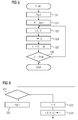
- the controller checks 15 according to FIG. 6 in a step S31, whether to execute the normal mode or the determination mode.
- the controller 5 may check in step S31 whether an appropriate mode is given by an operator (not shown). Under certain circumstances, the control device 5 can also recognize automatically whether it should execute the normal mode or the determination mode.
- step S32 corresponds to the determination mode.
- the control device 5 carries out the determination method according to the invention, which is described above in connection with FIG FIG. 2 was explained.
- Steps S33 and S34 correspond to the normal mode.
- the control device 5 determines - for example based on control commands that are given to the control device 5 by a superordinate device - a speed at which the electric machine 1 is to be operated, and thus a fundamental frequency f1.
- step S34 the control device 5 selects the associated optimized voltage curve U (t) for the corresponding fundamental frequency f1 and the modulation level G and reads this voltage curve U (t) from the memory 13 out.
- the read-out voltage curve U (t) is used by the control device 15 in step S34 for controlling the power converter 4.
- control device 5 of the converter 2 is preferably also able to carry out the optimization method according to the invention.
- control device 5 operates the inverter 2 according to FIG. 7 alternatively in an optimization mode or in normal mode.
- the controller 5 executes an optimization process (as explained above).
- the controller 5 executes the determination mode in the optimization mode.
- the controller 5 checks in a step S36 whether to execute the normal mode or the optimization mode.
- the controller 5 may check in step S31 whether an appropriate mode is given by an operator (not shown).
- the control device 5 can also recognize automatically when it is first connected to the electric machine 1. In this case, an execution of the optimization mode can be triggered automatically and also terminated.
- step S37 the controller 5 executes a procedure as described above in connection with FIG. 5 was explained. In particular, in the context of step S37, the storage of the optimized voltage profiles U (t) for the various fundamental frequencies f1 in the memory 13 takes place. If the control device 5 is to execute the normal mode, it proceeds to steps S33 and S34, which have already been mentioned above With FIG. 6 were explained.
- the present invention has many advantages.
- both the electrical transfer function GE and the mechanical transfer functions GMP, GMR can be measured quickly (in a few minutes) and reliably.
- no additional equipment is required for carrying out the determination method according to the invention and also for carrying out the optimization method according to the invention. Rather, it is possible to use the inverter 2 and its control device 5.
Landscapes
- Engineering & Computer Science (AREA)
- Power Engineering (AREA)
- Physics & Mathematics (AREA)
- General Physics & Mathematics (AREA)
- Automation & Control Theory (AREA)
- Control Of Ac Motors In General (AREA)
- Control Of Electric Motors In General (AREA)
Abstract
Durch entsprechende Ansteuerung eines eine elektrische Maschine (1) an ein elektrisches Versorgungsnetz (3) angeschaltenden Umrichters (2) wird ein Hochlauf der elektrischen Maschine (1) durchgeführt. Beim Hochlauf der elektrischen Maschine (1) wird die elektrische Maschine (1) mit einem jeweiligen Spannungsverlauf beaufschlagt, dessen Spannungsspektrum zusätzlich zu einer Grundschwingung bei einer Grundfrequenz (f1) vorbestimmte Anteile vorbestimmter Oberschwingungen enthält. Mittels entsprechender Sensoren (10 bis 12) werden sich ergebende Strom- und mechanische Schwingungsverläufe erfasst. Anhand des jeweiligen Stromspektrums und des jeweiligen Spannungsspektrums wird eine elektrische Übertragungsfunktion (GE) bei mindestens einer der Oberschwingungen der Grundfrequenz (f1) ermittelt. Anhand des jeweiligen Stromspektrums wird ein korrespondierendes jeweiliges Radialkraftspektrum im Luftspalt der elektrischen Maschine (1) ermittelt. Anhand des jeweiligen Radialkraftspektrums und des mit dem mechanischen Schwingungsverlauf korrespondierenden Schwingungsspektrums wird für mindestens eine Oberschwingung der Grundfrequenz (f1) mindestens eine mechanische Übertragungsfunktion (GMP, GMR) der elektrischen Maschine (1) ermittelt.By appropriate control of an electric machine (1) to an electrical supply system (3) connected to the inverter (2), a run-up of the electric machine (1) is performed. During startup of the electric machine (1), the electrical machine (1) is acted upon by a respective voltage curve, the voltage spectrum of which, in addition to a fundamental oscillation at a fundamental frequency (f1), contains predetermined proportions of predetermined harmonics. By means of corresponding sensors (10 to 12) resulting current and mechanical vibration waveforms are detected. Based on the respective current spectrum and the respective voltage spectrum, an electrical transfer function (GE) is determined for at least one of the harmonics of the fundamental frequency (f1). Based on the respective current spectrum, a corresponding respective radial force spectrum in the air gap of the electric machine (1) is determined. At least one mechanical transfer function (GMP, GMR) of the electric machine (1) is determined for at least one harmonic of the fundamental frequency (f1) on the basis of the respective radial force spectrum and the oscillation spectrum corresponding to the mechanical oscillation profile.
Description
Die vorliegende Erfindung betrifft ein Ermittlungsverfahren zum Ermitteln einer elektrischen und mindestens einer mechanischen Übertragungsfunktion einer elektrischen Maschine, die über einen Umrichter an ein elektrisches Versorgungsnetz angeschaltet wird,
- wobei die elektrische Übertragungsfunktion angibt, in welchem Umfang bei einer Anregung mit einer Spannung einer bestimmten Frequenz in der elektrischen Maschine ein Strom gleicher Frequenz angeregt wird,
- wobei die mindestens eine mechanische Übertragungsfunktion angibt, in welchem Umfang bei einer Anregung mit einer Radialkraft im Luftspalt der elektrischen Maschine, die eine bestimmte Frequenz aufweist, in der elektrischen Maschine eine mechanische Schwingung gleicher Frequenz angeregt wird.
- wherein the electrical transfer function indicates to what extent, when excited with a voltage of a certain frequency in the electric machine, a current of the same frequency is excited,
- wherein the at least one mechanical transfer function indicates the extent to which excitation with a radial force in the air gap of the electric machine, which has a certain frequency, in the electric machine, a mechanical vibration of the same frequency is excited.
Als mechanische Schwingung wird im Rahmen der vorliegenden Erfindung sowohl eine Schwingung eines Elements der elektrischen Maschine angesehen (beispielsweise eines Gehäuses oder eines Blechpakets) als auch eine akustische Schwingung in der die elektrische Maschine umgebenden Luft. Zur sprachlichen Unterscheidung wird nachfolgend der Begriff mechanische Schwingung stets als Oberbegriff verwendet, der sowohl eine Schwingung eines Elements der elektrischen Maschine als auch eine akustische Schwingung umfasst. Sofern ausschließlich eine Schwingung eines Elements der elektrischen Maschine gemeint ist, wird nachfolgend der Begriff Vibration verwendet. Akustische Schwingungen werden als solche bezeichnet. In analoger Weise werden auch entsprechende Übertragungsfunktionen als mechanische, vibratorische oder akustische Übertragungsfunktion bezeichnet.In the context of the present invention, mechanical oscillation is taken to mean both a vibration of an element of the electrical machine (for example a housing or a laminated core) and an acoustic oscillation in the air surrounding the electrical machine. For linguistic distinction, the term mechanical vibration is always used below as a generic term, which includes both a vibration of an element of the electric machine and an acoustic vibration. If only one oscillation of an element of the electrical machine is meant, the term vibration is used below. Acoustic vibrations are referred to as such. Analogously, corresponding transfer functions are also referred to as mechanical, vibratory or acoustic transfer functions.
Die vorliegende Erfindung betrifft weiterhin einen Umrichter für eine elektrische Maschine, über welchen die elektrische Maschine an ein elektrisches Versorgungsnetz angeschaltet wird, wobei der Umrichter eine Steuereinrichtung aufweist.The present invention further relates to a converter for an electrical machine, via which the electric machine is connected to an electrical supply network, wherein the converter has a control device.
Die vorliegende Erfindung betrifft weiterhin ein Steuerprogramm für eine softwareprogrammierbare Steuereinrichtung eines derartigen Umrichters, wobei das Steuerprogramm Maschinencode umfasst, der von der Steuereinrichtung unmittelbar ausführbar ist und dessen Ausführung durch die Steuereinrichtung die Betriebsweise des Umrichters festlegt.The present invention further relates to a control program for a software programmable control device of such an inverter, wherein the control program comprises machine code which is directly executable by the control device and whose execution by the control device determines the operation of the inverter.
Die oben genannten Gegenstände sind allgemein bekannt.The above objects are well known.
Beim Betrieb einer elektrischen Maschine an einem Umrichter entstehen zusätzlich zu den unvermeidbaren Betriebsgeräuschen der elektrischen Maschine zusätzliche Geräusche, welche von den Harmonischen des Stromes verursacht werden. Die Harmonischen des Stromes rufen im Luftspalt der elektrischen Maschine Radialkraftwellen hervor, das heißt Kraftwellen, bei denen die jeweilige Kraft in Radialrichtung der elektrischen Maschine wirkt. Die Radialkraftwellen sind die eigentliche Ursache für die zusätzlichen Geräusche. Die zusätzlichen Geräusche hängen in starkem Umfang von den Eigenschaften der Modulation des Umrichters wie beispielsweise der Pulsfrequenz ab. Die zusätzlichen Geräusche entstehen unabhängig davon, ob die elektrische Maschine als Motor oder als Generator betrieben wird.When an electric machine is operated on a converter, in addition to the unavoidable operating noises of the electric machine, additional noises are produced, which are caused by the harmonics of the current. The harmonics of the current cause radial force waves in the air gap of the electric machine, that is to say force waves in which the respective force acts in the radial direction of the electric machine. The radial force waves are the actual cause of the additional noise. The additional noise depends to a large extent on the characteristics of the modulation of the converter, such as the pulse frequency. The additional noise occurs regardless of whether the electric machine is operated as a motor or as a generator.
Die zusätzlichen Geräusche haben ihre Ursache im Wesentlichen darin, dass die durch den Umrichter gepulste Spannung in der Wicklung der elektrischen Maschine Ströme hervorruft, die einen hohen Gehalt an Oberschwingungen aufweisen. Dadurch entstehen im Luftspalt der elektrischen Maschine höherfrequente Magnetfelder, die zu magnetisch verursachten Geräuschen führen. Die höherfrequenten Magnetfelder führen ferner zu Verformungen des Blechpakets der elektrischen Maschine in radialer Richtung und versetzen es dadurch in Schwingungen. Diese Schwingungen sind die Ursache für die zusätzlichen Geräuschemissionen. Oftmals treten die zusätzlichen Geräusche in erheblichem Umfang in einem Frequenzbereich zwischen 1 kHz und 5 kHz auf. Insbesondere für diesen Frequenzbereich ist das menschliche Ohr besonders empfindlich.The additional noise is mainly due to the fact that the voltage pulsed by the inverter in the winding of the electric machine causes currents which have a high content of harmonics. This results in higher frequency magnetic fields in the air gap of the electric machine, which lead to magnetically caused noises. The higher-frequency magnetic fields also lead to deformations of the laminated core of the electric machine in the radial direction and thereby make it vibrate. These Vibrations are the cause of the additional noise emissions. Often the additional noise occurs to a considerable extent in a frequency range between 1 kHz and 5 kHz. Especially for this frequency range, the human ear is particularly sensitive.
Zur theoretischen, modellgestützten Analyse der entsprechenden Geräusche und deren späterer Minimierung sollten nicht nur die Eigenschaften der Anregung (d.h. die Harmonischen des Stromes und die dadurch verursachten Radialkräfte), sondern auch die mechanische Übertragungsfunktion der elektrischen Maschine bekannt sein. Es ist daher ein entsprechendes Ermittlungsverfahren erforderlich.For theoretical, model-based analysis of the corresponding noises and their subsequent minimization, not only the properties of the excitation (i.e., the harmonics of the current and the radial forces caused thereby) but also the mechanical transfer function of the electric machine should be known. Therefore, an appropriate investigation is required.
Es ist zwar relativ einfach möglich, die elektrische Übertragungsfunktion zu bestimmen, da hierfür lediglich die an die elektrische Maschine angelegte Spannung und die in der elektrischen Maschine durch die angelegte Spannung hervorgerufenen Ströme gemessen werden müssen. Es ist jedoch schwierig, die durch die Ströme hervorgerufenen Radialkräfte im Luftspalt der elektrischen Maschine durch Messungen zu bestimmen, da hierfür die magnetischen Induktionswellen im Luftspalt gemessen werden müssten. Oftmals werden die magnetischen Induktionswellen daher im Stand der Technik durch analytische Gleichungen oder Berechnungen anhand von Finite-Element-Methoden bestimmt. Die akustische Übertragungsfunktion der elektrischen Maschine kann beispielsweise bei bekannter Anregung durch die Radialkraftwellen durch Messungen des Schalldruckpegels unter Berücksichtigung von Abstand des Mikrofons von der elektrischen Maschine und anderen Umgebungsbedingungen oder noch besser durch direkte Messung der Schallleistung - gegebenenfalls in Verbindung mit Messungen des Schalldruckpegels - berechnet werden. Die vibratorische Übertragungsfunktion wird üblicherweise durch eine sogenannte Modalanalyse gemessen. Zu diesem Zweck wird das Gehäuse der elektrischen Maschine mittels eines sogenannten Modalhammers zu Schwingungen angeregt. Die angeregten Schwingungen werden im Stand der Technik mittels Schwingungssensoren gemessen.Although it is relatively easy to determine the electrical transfer function, since this only the voltage applied to the electric machine voltage and caused in the electrical machine by the applied voltage currents must be measured. However, it is difficult to determine the radial forces caused by the currents in the air gap of the electrical machine by measurements, since for this the magnetic induction waves would have to be measured in the air gap. Often, therefore, the magnetic induction waves are determined in the prior art by analytical equations or calculations using finite element methods. The acoustic transfer function of the electrical machine can be calculated, for example, with known excitation by the radial force waves by measurements of the sound pressure level taking into account distance of the microphone from the electrical machine and other environmental conditions or even better by direct measurement of sound power - possibly in conjunction with measurements of the sound pressure level , The vibratory transfer function is usually measured by a so-called modal analysis. For this purpose, the housing of the electric machine is excited to vibrate by means of a so-called modal hammer. The excited vibrations are measured in the prior art by means of vibration sensors.
Aus der Dissertation "Lärmerzeugung in wechselrichtergespeisten Asynchronmaschinen und Lärmbeeinflussung durch optimierte Pulsmuster" von T. Eilinger, Eidgenössische Technische Hochschule Zürich, 1997, ist ein Verfahren zur Messung der mechanischen und der akustischen Übertragungsfunktion bekannt. Bei diesem Verfahren werden mittels einer dreiphasigen Signalquelle und eines Leistungsverstärkers am Klemmenkasten einer sinusgespeisten elektrischen Maschine der eigentlichen Speisung Oberschwingungen mit einem Frequenzabstand von 1 kHz überlagert. Die Oberschwingungen weisen die gleiche Drehrichtung wie die eigentliche Speisung auf. Die Wechselwirkung jeder Oberschwingung mit der Grundschwingung verursacht zwei Radialkraftwellen im Luftspalt, nämlich je eine Radialkraftwelle mit der Summe der beiden Frequenzen und der Differenz der beiden Frequenzen. Die Radialkraftwelle mit der Differenzfrequenz ist eine pulsierende Kraftwelle. Die Radialkraftwelle mit der Summenfrequenz ist eine drehende Kraftquelle, welche eine Ordnungszahl gleich der doppelten Polpaarzahl der Grundschwingung aufweist. In der genannten Dissertation wird vorgeschlagen, die Frequenz der Oberwellen jeweils um 50 Hz zu ändern und anschließend den Schalldruckpegel zu messen, um die Übertragungsfunktion für die pulsierenden und die rotierenden Komponenten als Funktion der Frequenz zu bestimmen.From the dissertation "Noise generation in inverter-fed asynchronous machines and noise influence by optimized pulse patterns" by T. Eilinger, Swiss Federal Institute of Technology, Zurich, 1997, a method for measuring the mechanical and acoustic transfer function is known. In this method, by means of a three-phase signal source and a power amplifier harmonics are superimposed on the terminal box of a sinusoidal-powered electric machine of the actual supply harmonics with a frequency spacing of 1 kHz. The harmonics have the same direction of rotation as the actual supply. The interaction of each harmonic with the fundamental vibration causes two radial force waves in the air gap, namely one radial force wave with the sum of the two frequencies and the difference between the two frequencies. The radial force wave with the difference frequency is a pulsating force wave. The radial force wave with the sum frequency is a rotating power source having an atomic number equal to twice the number of pole pairs of the fundamental. In the mentioned dissertation it is proposed to change the frequency of the harmonics by 50 Hz in each case and then to measure the sound pressure level in order to determine the transfer function for the pulsating and the rotating components as a function of the frequency.
Das in der Dissertation vorgeschlagene Verfahren erfordert eine zusätzliche Einrichtung mit Leistungsverstärkern, Kondensatoren, Induktanzen usw. für die Überlagerung der Oberschwingungen, die im Sinusbetrieb nicht vorhanden sind. Weiterhin ist das in der Dissertation vorgeschlagene Verfahren in der weit überwiegenden Mehrzahl von Fällen nur in einer reinen Testumgebung realisierbar, weil in praktischen Anwendungen die elektrischen Maschinen nicht sinusgespeist, sondern umrichtergespeist sind. Die Umrichterspeisung weist jedoch selbst bereits höherfrequente Komponenten auf, die sich mit den Anregungen überlagern können. Dadurch ist das Verfahren der Dissertation in der Praxis schwierig anzuwenden, insbesondere nicht vor Ort bei einem schon installierten System mit Umrichter und elektrischer Maschine. Darüber hinaus ist das in der Dissertation vorgeschlagene Verfahren aufwändig.The method proposed in the dissertation requires an additional device with power amplifiers, capacitors, inductances, etc. for the superposition of the harmonics that are not present in sine mode. Furthermore, in the overwhelming majority of cases, the method proposed in the dissertation can only be realized in a pure test environment, because in practical applications the electrical machines are not sinusoidally fed, but rather are converter-fed. However, the converter feed itself already has higher-frequency components which can overlap with the excitations. As a result, the method of the dissertation in practice is difficult to apply, especially not on site in an already installed system with inverter and electrical machine. In addition, the method proposed in the dissertation is laborious.
Die Aufgabe der vorliegenden Erfindung besteht darin, Möglichkeiten zu schaffen, auch bei einer umrichtergespeisten elektrischen Maschine auf einfache und zuverlässige Weise die elektrische und die mechanische Übertragungsfunktion ermitteln zu können.The object of the present invention is to provide opportunities to be able to determine the electrical and the mechanical transfer function in a converter-fed electrical machine in a simple and reliable manner.
Die Aufgabe wird durch ein Ermittlungsverfahren mit den Merkmalen des Anspruchs 1 gelöst. Vorteilhafte Ausgestaltungen des erfindungsgemäßen Ermittlungsverfahrens sind Gegenstand der abhängigen Ansprüche 2 bis 7.The object is achieved by a preliminary investigation with the features of
Erfindungsgemäß wird im Rahmen der Ermittlung der Übertragungsfunktionen für die Anregung der elektrischen Maschine der Umrichter selbst verwendet. Die entsprechenden erfindungsgemäßen Merkmale bestehen darin,
- dass durch entsprechende Ansteuerung des Umrichters ein Hochlauf der elektrischen Maschine von einer Anfangsdrehzahl zu einer Enddrehzahl durchgeführt wird,
- dass beim Hochlauf der elektrischen Maschine die elektrische Maschine mit einem jeweiligen Spannungsverlauf beaufschlagt wird,
- dass der jeweilige Spannungsverlauf derart bestimmt ist, dass ein zugehöriges Spannungsspektrum zusätzlich zu einer Grundschwingung bei einer Grundfrequenz vorbestimmte Anteile vorbestimmter Oberschwingungen der Grundfrequenz enthält,
- dass mittels entsprechender Sensoren zumindest ein sich ergebender korrespondierender jeweiliger Stromverlauf und ein sich ergebender korrespondierender mechanischer Schwingungsverlauf erfasst werden,
- dass anhand des jeweiligen Stromverlaufs ein korrespondierendes jeweiliges Stromspektrum ermittelt wird und anhand des jeweiligen Stromspektrums und des jeweiligen Spannungsspektrums die elektrische Übertragungsfunktion bei mindestens einer der vorbestimmten Oberschwingungen der Grundfrequenz ermittelt wird,
- dass anhand des jeweiligen Stromspektrums ein korrespondierendes jeweiliges Radialkraftspektrum im Luftspalt der elektrischen Maschine ermittelt wird,
- dass anhand des erfassten jeweiligen mechanischen Schwingungsverlaufs ein korrespondierendes jeweiliges Schwingungsspektrum ermittelt wird und
- dass anhand des jeweiligen Radialkraftspektrums und des jeweiligen Schwingungsspektrums für mindestens eine Oberschwingung der Grundfrequenz die mindestens eine mechanische Übertragungsfunktion der elektrischen Maschine ermittelt wird.
- that, by appropriate control of the converter, a run-up of the electric machine from an initial speed to a final speed is carried out,
- that during the run-up of the electrical machine, the electrical machine is subjected to a respective voltage curve,
- that the respective voltage profile is determined such that an associated voltage spectrum in addition to a fundamental at a fundamental frequency contains predetermined proportions of predetermined harmonics of the fundamental frequency,
- that by means of corresponding sensors at least one resulting corresponding respective current profile and a resulting corresponding mechanical waveform are detected,
- in that a corresponding respective current spectrum is determined on the basis of the respective current profile and, based on the respective current spectrum and the respective voltage spectrum, the electrical transfer function at least one of the predetermined harmonics of the fundamental frequency is determined
- that a corresponding respective radial force spectrum in the air gap of the electrical machine is determined on the basis of the respective current spectrum,
- that a corresponding respective oscillation spectrum is determined on the basis of the detected respective mechanical oscillation profile, and
- in that the at least one mechanical transfer function of the electrical machine is determined on the basis of the respective radial force spectrum and the respective oscillation spectrum for at least one harmonic of the fundamental frequency.
Bei der mechanischen Übertragungsfunktion kann es sich, wie bereits erwähnt, alternativ um eine vibratorische oder um eine akustische Übertragungsfunktion handeln. Es ist jedoch selbstverständlich auch möglich, beide Übertragungsfunktionen zu ermitteln.As already mentioned, the mechanical transfer function may alternatively be a vibratory or an acoustic transfer function. However, it is of course also possible to determine both transfer functions.
In aller Regel ist die elektrische Maschine dreiphasig ausgebildet. In diesem Fall können prinzipbedingt Oberschwingungen, deren Frequenz einem durch 3 teilbaren ganzzahligen Vielfachen der Grundfrequenz entspricht, nicht auftreten. Allgemein gilt dies bei einer k-phasigen Maschine für durch k teilbare ganzzahlige Vielfache der Grundfrequenz. Weiterhin sind insbesondere diejenigen Oberschwingungen von Bedeutung, deren Frequenz ein ungeradzahliges Vielfaches der Grundfrequenz ist.As a rule, the electric machine is designed in three phases. In this case, harmonics whose frequency corresponds to a divisible by 3 integer multiples of the fundamental frequency can not occur due to the principle. In general, this applies to a k-phase machine for integer multiples of the fundamental frequency divisible by k. Furthermore, those harmonics whose frequency is an odd multiple of the fundamental frequency are of particular importance.
Es ist von Vorteil, dass für unmittelbar aufeinanderfolgende Oberschwingungen der Spannungen die Beziehung F2 - F1 > 2f1 gilt, wobei F1 und F2 die Frequenzen der beiden Oberschwingungen und f1 die Grundfrequenz sind. Durch diese Vorgehensweise wird erreicht, dass jede angeregte Radialkraftwelle durch eine einzige im Spannungsspektrum auftretende Frequenz angeregt wird.It is advantageous that for immediately successive harmonics of the voltages the relationship F2 - F1> 2f1 applies, where F1 and F2 are the frequencies of the two harmonics and f1 the fundamental frequency. This procedure ensures that each excited radial force wave is excited by a single frequency occurring in the voltage spectrum.
Vorzugsweise gilt für die Oberschwingungen der Spannungen die Beziehung F = nf1 gilt, wobei F die Frequenz der jeweiligen Oberschwingung und f1 die Grundfrequenz sind, wobei n eine natürliche Zahl ist, welche eine der Beziehungen n = 2km + 1 und n = 2km - 1 erfüllt, wobei k die Anzahl an Phasen der elektrischen Maschine ist und m eine natürliche Zahl größer als 1 ist. m ist vorzugsweise insbesondere größer als 3, größer als 4 und ganz besonders bevorzugt größer als 6. m kann auch noch größere Werte aufweisen, beispielsweise 8, 10 oder 12. Dadurch wird eine besonders saubere Trennung der einzelnen angeregten Schwingungen erreicht.Preferably, for the harmonics of the voltages, the relation F = nf1 applies, where F is the frequency of the respective harmonic and f1 is the fundamental frequency, where n is a natural number satisfying one of the relationships n = 2km + 1 and n = 2km-1 where k is the number of phases of the electric machine and m is a natural number greater than one. m is preferably in particular greater than 3, greater than 4 and very particularly preferably greater than 6. m may also have larger values, for example 8, 10 or 12. This results in a particularly clean separation of the individual excited vibrations.
Das Radialkraftspektrum im Luftspalt der elektrischen Maschine umfasst pulsierende und rotierende Radialkraftwellen. Vorzugsweise wird für die pulsierenden und für die rotierenden Radialkraftwellen je eine eigene mechanische Übertragungsfunktion ermittelt.The radial force spectrum in the air gap of the electric machine comprises pulsating and rotating radial force waves. Preferably, each of its own mechanical transfer function is determined for the pulsating and for the rotating radial force waves.
Je nach Lage des Einzelfalls kann der mechanische Schwingungsverlauf eine Schwingung eines Elements der elektrischen Maschine und/oder eine Schallabstrahlung sein.Depending on the location of the individual case, the mechanical vibration course may be a vibration of an element of the electrical machine and / or a sound radiation.
Es ist möglich, im Rahmen der Ermittlung der elektrischen Übertragungsfunktion dasjenige Spannungsspektrum zu verwenden, das der Ansteuerung des Umrichters zugrundeliegt. Alternativ ist es möglich, dass der Spannungsverlauf erfasst wird und dass anhand des erfassten Spannungsverlaufs das Spannungsspektrum ermittelt wird. In diesem Fall wird also das tatsächliche Spannungsspektrum verwendet, nicht das theoretisch erwartete Spannungsspektrum.It is possible to use in the context of determining the electrical transfer function that voltage spectrum that underlies the control of the inverter. Alternatively, it is possible for the voltage profile to be detected and for the voltage spectrum to be determined on the basis of the detected voltage profile. In this case, the actual voltage spectrum is used, not the theoretically expected voltage spectrum.
Es ist möglich, dass das entsprechende Ermittlungsverfahren in einer Testumgebung ausgeführt wird. Vorzugsweise jedoch wird das Ermittlungsverfahren von einer Steuereinrichtung des Umrichters in einem Ermittlungsmodus des Umrichters ausgeführt. Dadurch ist insbesondere auch eine Ausführung des Ermittlungsverfahrens vor Ort möglich. Beispielsweise kann das Ermittlungsverfahren jedes Mal erneut ausgeführt werden, wenn das aus Umrichter und elektrischer Maschine bestehende System miteinander verbunden wird, wenn also eine erstmalige Verschaltung von Umrichter und elektrischer Maschine erfolgt oder wenn entweder der Umrichter oder die elektrische Maschine ausgetauscht werden.It is possible that the corresponding investigation procedure will be performed in a test environment. Preferably, however, the determination process is performed by a controller of the inverter in a detection mode of the inverter. This makes it possible in particular to carry out the investigation on site. For example, the discovery process can be re-executed each time the system comprising the converter and the electrical machine is connected to one another, ie when a first connection between the converter and the electrical machine takes place or when either the converter or the electrical machine is replaced.
Ausgehend von den ermittelten Übertragungsfunktionen kann eine Optimierung vorgenommen werden. Die Optimierung hat in der Regel das Ziel, Schwingungen von Elementen der elektrischen Maschine und/oder das im Betrieb der elektrischen Maschine entstehende Geräusch zu minimieren. Es sind jedoch auch andere Optimierungen denkbar. Es ist möglich, ausgehend von der Ermittlung der Übertragungsfunktionen mechanische Eigenschaften der elektrischen Maschine zu variieren. Vorzugsweise besteht ein Optimierungsverfahren zur Optimierung einer mechanischen Schwingung einer elektrischen Maschine, die über einen Umrichter an ein elektrisches Versorgungsnetz angeschaltet wird, jedoch darin, dass entsprechend Anspruch 8
- mittels eines erfindungsgemäßen Ermittlungsverfahrens (wie obenstehend erläutert) eine elektrische und mindestens eine mechanische Übertragungsfunktion der elektrischen Maschine ermittelt werden und
- unter Verwendung der ermittelten Übertragungsfunktionen gemäß einem Optimierungskriterium für Frequenzen und Aussteuergrade der elektrischen Maschine ein jeweiliger optimierter Spannungsverlauf ermittelt und im Umrichter hinterlegt wird.
- an electrical and at least one mechanical transfer function of the electrical machine can be determined by means of a determination method according to the invention (as explained above) and
- determined using the determined transfer functions according to an optimization criterion for frequencies and Aussteuergrade the electric machine, a respective optimized voltage waveform and stored in the inverter.
In Umrichter wird also ein zweidimensionales Feld mit jeweiligen optimierten Spannungsverläufen als Funktion der Frequenz und des Aussteuergrades hinterlegt.Inverters thus a two-dimensional field with respective optimized voltage curves as a function of the frequency and the Aussteuergrades is deposited.
Der Aussteuergrad G der elektrischen Maschine ist üblicherweise definiert als 
wobei ULL der Effektivwert der Grundwelle der an der elektrischen Maschine anliegenden Leiter-Leiter-Spannung und UZK die Zwischenkreisspannung des den Umrichter speisenden Zwischenkreises sind.The Aussteuergrad G of the electric machine is usually defined as
where ULL is the rms value of the fundamental wave of the applied to the electric machine phase-to-wire voltage and UZK the DC link voltage of the inverter feeding the DC link.
Variiert werden können im Rahmen des Optimierungsverfahrens beispielsweise das Modulationsverfahren des Umrichters, dessen Schaltfrequenz und das Schaltmuster.In the context of the optimization method, for example, the modulation method of the converter, its switching frequency and the switching pattern can be varied.
Es ist möglich, dass das Optimierungsverfahren stets in unveränderter Form durchgeführt wird. Vorzugsweise ist es jedoch möglich, dass einer das Optimierungsverfahren durchführenden Einrichtung das Optimierungskriterium und/oder Parameter des Ermittlungsverfahrens von außen vorgegeben werden. Dies erhöht die Flexibilität des Optimierungsverfahrens. Parameter des Ermittlungsverfahrens können beispielsweise ein Frequenzbereich für die Grundschwingung der Spannung oder Anteile von Oberschwingungen der Spannung sein.It is possible that the optimization process is always carried out in unchanged form. Preferably, however, it is possible for a device carrying out the optimization method to specify the optimization criterion and / or parameters of the determination method from the outside. This increases the flexibility of the optimization process. Parameters of the determination method may be, for example, a frequency range for the fundamental of the voltage or components of harmonics of the voltage.
Es ist möglich, dass das entsprechende Optimierungsverfahren in einer Testumgebung ausgeführt wird. Vorzugsweise jedoch wird das Optimierungsverfahren von einer Steuereinrichtung des Umrichters in einem Optimierungsmodus des Umrichters ausgeführt. In diesem Fall liest die Steuereinrichtung in einem Normalmodus des Umrichters die im Optimierungsmodus im Umrichter hinterlegten optimierten Spannungsverläufe aus und verwendet sie. Dadurch ist insbesondere auch eine Ausführung des Optimierungsverfahrens vor Ort möglich. Beispielsweise kann - analog zum Ermittlungsverfahren - das Optimierungsverfahren jedes Mal erneut ausgeführt werden, wenn das aus Umrichter und elektrischer Maschine bestehende System miteinander verbunden wird, wenn also eine erstmalige Verschaltung von Umrichter und elektrischer Maschine erfolgt oder wenn entweder der Umrichter oder die elektrische Maschine ausgetauscht werden.It is possible that the corresponding optimization procedure will be executed in a test environment. Preferably, however, the optimization method is executed by a controller of the inverter in an optimization mode of the inverter. In this case, in a normal mode of the converter, the control device reads out and uses the optimized voltage profiles stored in the converter in the optimization mode. As a result, execution of the optimization method on site is possible in particular. For example, analogous to the determination method, the optimization method can be executed again each time when the system comprising the converter and the electrical machine is connected to one another, ie when a first connection of the converter and the electrical machine takes place or if either the converter or the electrical machine is replaced ,
Die Aufgabe wird weiterhin durch einen Umrichter mit den Merkmalen des Anspruchs 11 gelöst. Vorteilhafte Ausgestaltungen des erfindungsgemäßen Umrichters sind Gegenstand der abhängigen Ansprüche 12 und 13.The object is further achieved by a converter with the features of
Erfindungsgemäß wird ein Umrichter der eingangs genannten Art dadurch ausgestaltet, dass die Steuereinrichtung den Umrichter in einem Normalmodus oder in einem Ermittlungsmodus betreibt, dass die Steuereinrichtung im Ermittlungsmodus ein erfindungsgemäßes Ermittlungsverfahren ausführt und dass die Steuereinrichtung im Normalmodus im Umrichter hinterlegte Spannungsverläufe ausliest und verwendet.According to the invention, an inverter of the aforementioned type is configured in that the control device operates the converter in a normal mode or in a determination mode, that the control device executes a determination method according to the invention in the determination mode and that the control device reads out and uses voltage profiles stored in the converter in the normal mode.
Vorzugsweise führt die Steuereinrichtung den Ermittlungsmodus im Rahmen eines Optimierungsmodus aus. In diesem Fall führt die Steuereinrichtung im Optimierungsmodus ein erfindungsgemäßes Optimierungsverfahren aus. Weiterhin liest sie im Normalmodus die im Optimierungsmodus im Umrichter hinterlegten optimierten Spannungsverläufe aus und verwendet sie.The control device preferably executes the determination mode in the context of an optimization mode. In this case, the control device executes an optimization method according to the invention in the optimization mode. Furthermore, in normal mode, it reads out and uses the optimized voltage profiles stored in the inverter in the optimization mode.
Vorzugsweise ist die Steuereinrichtung als softwareprogrammierbare Einrichtung ausgebildet ist.Preferably, the control device is designed as a software programmable device.
Die Aufgabe wird weiterhin durch ein Steuerprogramm mit den Merkmalen des Anspruchs 14 gelöst. Erfindungsgemäß bewirkt die Ausführung des Maschinencodes, dass der Umrichter erfindungsgemäß ausgebildet ist.The object is further achieved by a control program having the features of claim 14. According to the invention causes the execution of the machine code, that the inverter is designed according to the invention.
Das Steuerprogramm kann der Steuereinrichtung auf beliebigem Wege zugeführt werden, beispielsweise über eine Rechner-Rechner-Anbindung wie ein LAN oder das Internet. Auch andere Schnittstellen sind möglich, beispielsweise eine Profibus-Schnittstelle. Alternativ ist es möglich, das Steuerprogramm der Steuereinrichtung über einen (mobilen) Datenträger zuzuführen, auf dem das Steuerprogramm in maschinenlesbarer Form - insbesondere in elektronischer Form - gespeichert ist. Unabhängig davon, auf welche Weise das Steuerprogramm der Steuereinrichtung zugeführt wird, ist es jedoch innerhalb der Steuereinrichtung in einem der Steuereinrichtung fest oder temporär zugeordneten Datenträger hinterlegt.The control program can be supplied to the control device in any way, for example via a computer-computer connection such as a LAN or the Internet. Other interfaces are possible, such as a Profibus interface. Alternatively, it is possible to supply the control program to the control device via a (mobile) data carrier on which the control program is stored in machine-readable form, in particular in electronic form. Regardless of how the control program is supplied to the control device, however, it is stored within the control device in a permanently or temporarily assigned to the control device data carrier.
Die oben beschriebenen Eigenschaften, Merkmale und Vorteile dieser Erfindung sowie die Art und Weise, wie diese erreicht werden, werden klarer und deutlicher verständlich im Zusammenhang mit der folgenden Beschreibung der Ausführungsbeispiele, die in Verbindung mit den Zeichnungen näher erläutert werden. Hierbei zeigen in schematischer Darstellung:
- FIG 1
- eine umrichtergespeiste elektrische Maschine,
- FIG 2
- ein Ablaufdiagramm,
- FIG 3
- ein Spannungsspektrum und ein entsprechendes Spektrum von Radialkraftwellen,
- FIG 4
- einen Spannungsverlauf und
- FIG 5
bis 7 - Ablaufdiagramme.
- FIG. 1
- an inverter-fed electrical machine,
- FIG. 2
- a flow chart,
- FIG. 3
- a voltage spectrum and a corresponding spectrum of radial force waves,
- FIG. 4
- a voltage curve and
- FIGS. 5 to 7
- Flowcharts.
Gemäß
Die Steuereinrichtung 5 ist in der Regel als softwareprogrammierbare Einrichtung ausgebildet. Sie weist daher intern zum einen einen Prozessor 6 auf, der ein Steuerprogramm 7 ausführt. Zum anderen weist die Steuereinrichtung 5 einen Programmspeicher 8 auf, in dem das Steuerprogramm 7 in maschinenlesbarer Form hinterlegt ist. Das Steuerprogramm 8 umfasst Maschinencode 9, der von der Steuereinrichtung 5 - genauer: von deren Prozessor 6 - unmittelbar ausführbar ist. Die Ausführung des Maschinencodes 9 durch die Steuereinrichtung 5 legt die Betriebsweise des Umrichters 2 fest. Insbesondere bewirkt die Ausführung des Maschinencodes 9, das der Umrichter 2 derart ausgebildet wird, dass er zumindest ein Ermittlungsverfahren, wie es nachstehend in Verbindung mit
Im Rahmen der Vorgehensweise von
Bei einer bestimmten Frequenz kann die Radialkraft im Luftspalt der elektrischen Maschine 1 alternativ als pulsierende Radialkraftwelle, als rotierende Radialkraftwelle oder als Linearkombination einer pulsierenden und einer rotierenden Radialkraftwelle ausgebildet sein. Das Radialkraftspektrum im Luftspalt der elektrischen Maschine 1 kann daher sowohl pulsierende als auch rotierende Radialkraftwellen umfassen. Eine rotierende Radialkraftwelle kann eine andere Anregung einer mechanischen Schwingung als eine pulsierende Radialkraftwelle gleicher Frequenz zur Folge haben. Es muss daher zwischen einer mechanischen Übertragungsfunktion GMP für pulsierende Radialkraftwellen und einer mechanischen Übertragungsfunktion GMR für rotierende Radialkraftwellen unterschieden werden.At a certain frequency, the radial force in the air gap of the
Zur Ermittlung der Übertragungsfunktionen GE, GMP, GMR wird gemäß
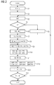
- In einem Schritt S1 wird eine Grundfrequenz f1 auf einen Anfangswert fa gesetzt. Der Anfangswert fa kann nach Bedarf bestimmt sein und beispielsweise im einstelligen Hertz-Bereich liegen. In einem Schritt S2 werden Schaltwinkel festgelegt, zu denen der Umrichter 2 jeweils geschaltet werden soll. In einem Schritt S3 wird anhand der Schaltwinkel das zugehörige Spannungsspektrum U(f) ermittelt. In einem Schritt S4 wird geprüft, ob Anteile ai (i = 1, 5, 7 usw.) von vorbestimmten Oberschwingungen der Grundfrequenz f1 gewünschte Werte aufweisen. Der Index i gibt an, um das Wievielfache der Grundfrequenz f1 es sich handelt. Der Anteil a1 ist beispielsweise der Anteil der Grundfrequenz f1, der Anteil a5 der Anteil der vierten Oberschwingung, das heißt einer Frequenz, die dem Fünffachen der Grundfrequenz f1 entspricht, usw.. Wenn die Prüfung des Schrittes S4 negativ verläuft, wird zu einem Schritt S5 übergegangen. Im Schritt S5 werden die Schaltwinkel variiert. Sodann wird zum Schritt S3 zurückgegangen. Wenn die Prüfung des Schrittes S4 hingegen positiv verläuft, wird zu einem Schritt S6 übergegangen.
- In a step S1, a fundamental frequency f1 is set to an initial value fa. The initial value fa can be determined as needed and, for example, in the single-digit hertz range. In a step S2, switching angles are set at which the
converter 2 is to be switched in each case. In a step S3, the associated voltage spectrum U (f) is determined on the basis of the switching angle. In a step S4, it is checked whether portions ai (i = 1, 5, 7, etc.) of predetermined harmonics of the fundamental frequency f1 have desired values. The index i indicates the multiple of the fundamental frequency f1. The proportion a1 is, for example, the proportion of the fundamental frequency f1, the fraction a5 the proportion of the fourth harmonic, that is, a frequency which is five times the fundamental frequency f1, etc. If the test of the step S4 is negative, a step S5 passed. In step S5, the switching angles are varied. Then, step S3 is returned. On the other hand, if the test of step S4 is positive, a step S6 is entered.
Die eine bevorzugte Ausgestaltung besteht darin, dass für unmittelbar aufeinanderfolgende Oberschwingungen der Spannungen die Beziehung F2 - F1 > 2f1 gilt. F1 und F2 sind in vorstehender Beziehung die Frequenzen der beiden betrachteten Oberschwingungen. Anders ausgedrückt: Wenn eine bestimmte, im Spannungsspektrum U(f) enthaltene Oberschwingung die Bedingung F=(6m+1)f1 erfüllt, ist im Spannungsspektrum U(f) keine Oberschwingung enthalten, die für denselben Wert der Zahl m die Bedingung F=(6m-1)f1 erfüllt. Ebenso gilt die umgekehrte Ausschlussbedingung. Von den beiden Oberschwingungen, von denen für einen bestimmten Wert der Zahl m je eine Oberschwingung eine der beiden Beziehungen F=(6m-1)f1 und F=(6m+1)f1 erfüllt, ist also stets entweder keine oder nur eine einzige Oberschwingung im Spannungsspektrum U(f) enthalten, nicht aber beide Oberschwingungen. Die Darstellung in
Die andere bevorzugte Ausgestaltung besteht darin, dass für die Oberschwingungen die Bedingung gilt, dass m größer als 1 ist. Die Zahl m kann beispielsweise den Wert 2, den Wert 3 oder den Wert 4 aufweisen. Auch noch größere Werte für die Zahl m sind möglich, beispielsweise m größer als 6 oder m größer als 10. Unabhängig vom konkreten Wert der Zahl m treten jedoch zumindest die 4. und die 6. Oberschwingung (deren Frequenzen gleich dem fünffachen bzw. dem siebenfachen der Grundfrequenz f1 sind) im Spannungsspektrum U(f) nicht auf.The other preferred embodiment is that the condition applies to the harmonics that m is greater than 1. The number m may, for example, have the
Die Schaltwinkel legen auch einen entsprechenden zeitlichen Spannungsverlauf U(t) fest.
Entsprechend dem in den Schritten S1 bis S5 ermittelten Spannungsverlauf U(t) wird in einem Schritt S6 der Umrichter 2 angesteuert. Die Steuereinrichtung 5 steuert also im Schritt S6 den Stromrichter 4 entsprechend an. Dadurch wird die elektrische Maschine 1 bei der jeweiligen Frequenz f1 mit dem entsprechenden Spannungsverlauf U(t) beaufschlagt. Die Ansteuerung des Umrichters 2 hat zur Folge, dass die elektrische Maschine 1 mit einer Drehzahl rotiert, die linear von der Grundfrequenz f1 abhängt.In accordance with the voltage curve U (t) determined in steps S1 to S5, the
Mittels entsprechender Stromsensoren 10 wird in einem Schritt S7 ein sich ergebender korrespondierender jeweiliger zeitlicher Stromverlauf I(t) erfasst. Der erfasste Stromverlauf I(t) kann beispielsweise der Steuereinrichtung 5 zugeführt werden. Weiterhin wird mittels entsprechender Schwingungssensoren 11, 12 ein sich ergebender korrespondierender mechanischer Schwingungsverlauf S(t) erfasst. Als Schwingungssensor 11, 12 kommt beispielsweise ein Sensor 11 in Frage, mittels dessen direkt eine Vibration eines mechanischen Elements der elektrischen Maschine 1 erfasst wird. In diesem Fall ist der erfasste mechanische Schwingungsverlauf S(t) eine Schwingung dieses Elements der elektrischen Maschine 1. Ebenso kommt als Schwingungssensor 11, 12 beispielsweise ein Mikrofon 12 in Frage. In diesem Fall ist der erfasste mechanische Schwingungsverlauf S(t) eine Schallabstrahlung der elektrischen Maschine 1. Es ist möglich, dass von den Schwingungssensoren 11, 12 nur einer vorhanden ist. Gleichermaßen können jedoch beide Schwingungssensoren 11, 12 vorhanden sein. Ferner kann gegebenenfalls zusätzlich zu dem Stromverlauf I(t) und dem Schwingungsverlauf S(t) auch der Spannungsverlauf U(t) erfasst werden.By means of corresponding
In einem Schritt S8 wird - beispielsweise durch Fouriertransformation - anhand des erfassten Stromverlaufs I(t) ein korrespondierendes jeweiliges Stromspektrum I(f) ermittelt. Falls im Rahmen des Schrittes S7 auch der Spannungsverlauf U(t) erfasst wird, wird weiterhin anhand des erfassten Spannungsverlaufs U(t) auch das (tatsächliche) Spannungsspektrum U(f) ermittelt. In einem Schritt S9 wird sodann - beispielsweise durch Quotientenbildung - anhand des jeweiligen Stromspektrums I(f) und des jeweiligen Spannungsspektrums U(f) bei mindestens einer der vorbestimmten Oberschwingungen der jeweiligen Grundfrequenz f1 die elektrische Übertragungsfunktion GE ermittelt. Wenn beispielsweise entsprechend der Darstellung in
Die Oberschwingungen im Stromspektrum I(f) bewirken im Zusammenwirken mit der Grundschwingung gemäß
Aus diesem Sachverhalt ist auch ersichtlich, warum von den beiden Oberschwingungen, von denen für einen bestimmten Wert der Zahl m je eine Oberschwingung eine der beiden Beziehungen F = (6m-1)f1 und F = (6m+1)f1 bzw. allgemein F = (2km+1)f1 und F = (2km-1)f1 erfüllt, nicht beide Oberschwingungen im Spannungsspektrum U(f) vorhanden sein sollten: Wenn dies der Fall wäre, wäre die resultierende pulsierende Radialkraftwelle FRP beim 6m-fachen (allgemein dem 2km-fachen) der Grundfrequenz f1 eine Überlagerung der durch die Oberschwingung mit dem (6m-1)-fachen der Grundfrequenz f1 hervorgerufenen pulsierenden Radialkraftwelle FRP mit der durch die Oberschwingung mit dem (6m+1)-fachen der Grundfrequenz f1 hervorgerufenen pulsierenden Radialkraftwelle FRP. Frequenzen der entstehenden mechanischen Schwingung S könnten daher nicht mehr eindeutig einer bestimmten anregenden Stromkomponente zugeordnet werden.It can also be seen from this fact why, of the two harmonics, of which for one particular value of the number m one harmonic each has one of the two relations F = (6m-1) f1 and F = (6m + 1) f1 or in general F = (2km + 1) f1 and F = (2km-1) f1, but both harmonics should not be present in the voltage spectrum U (f): If this were the case, the resulting pulsating radial force wave FRP would be 6m times (commonly the 2km times) of the fundamental frequency f1 superimposes the pulsating radial force wave FRP caused by the harmonic having the (6m-1) times the fundamental frequency f1 with the pulsating radial force wave FRP caused by the harmonic having the (6m + 1) times the fundamental frequency f1 , Frequencies of the resulting mechanical vibration S could therefore no longer be clearly assigned to a specific exciting current component.
Die rotierenden Radialkraftwellen FRR und die pulsierenden Radialkraftwellen FRP werden in einem Schritt S10 ermittelt. Die Ermittlung der Radialkraftwellen FRR, FRP ist Fachleuten als solches bekannt. Es werden zur Ermittlung der Radialkraftwellen FRR, FRP zusätzlich zur Stromverteilung im Frequenzbereich, also dem Stromspektrum I(f), konstruktive Gegebenheiten der elektrischen Maschine 1 benötigt. Im Schritt S10 erfolgt die Ermittlung der Radialkraftwellen FRR, FRP also anhand des jeweiligen Stromspektrums I(f). Die Gesamtheit der ermittelten Radialkraftwellen FRR, FRP entspricht einem Radialkraftspektrum FRR(f), FRP(f) im Luftspalt der elektrischen Maschine 1. Die Radialkraftwellen FRR, FRP sind, wie bereits erwähnt, die eigentliche Ursache für die magnetisch bedingten mechanischen Schwingungen S der elektrischen Maschine 1.The rotating radial force waves FRR and the pulsating radial force waves FRP are detected in a step S10. The determination of the radial force waves FRR, FRP is known to those skilled in the art. In order to determine the radial force waves FRR, FRP, in addition to the current distribution in the frequency range, that is to say the current spectrum I (f), constructional conditions of the
In einem Schritt S11 wird anhand des erfassten jeweiligen mechanischen Schwingungsverlaufs S(t) ein korrespondierendes jeweiliges Schwingungsspektrum S(f) ermittelt. Das Schwingungsspektrum S(f) enthält die gleichen Frequenzen wie das Radialkraftspektrum FRR(f), FRP(f). Es ist daher möglich, in einem Schritt S12 anhand des jeweiligen Radialkraftspektrums FRR(f), FRP(f) und des jeweiligen Schwingungsspektrums S(f) für mindestens eine Oberschwingung der Grundfrequenz f1 eine mechanische Übertragungsfunktion GMP, GMR der elektrischen Maschine 1 zu ermitteln. Auch hier kann die Ermittlung wieder durch Bildung des Quotienten erfolgen.In a step S11, a corresponding respective oscillation spectrum S (f) is determined on the basis of the detected respective mechanical oscillation profile S (t). The vibration spectrum S (f) contains the same frequencies as the radial force spectrum FRR (f), FRP (f). It is therefore possible to determine a mechanical transfer function GMP, GMR of the
Die Grundfrequenz f1 korrespondiert, wie bereits erwähnt, mit einer Drehzahl der elektrischen Maschine 1. Aufgrund des Anschaltens der elektrischen Maschine 1 an das elektrische Versorgungsnetz 3 erhöht sich während der Ausführung der Schritte S6 bis S12 die Drehzahl der elektrischen Maschine 1. Dies wird in einem Schritt S13 nachvollzogen, in dem die Grundfrequenz f1 um eine Frequenzänderung δf erhöht wird. Es ist möglich, dass zu diesem Zweck die aktuelle Drehzahl der elektrischen Maschine 1 erfasst wird. Es sind jedoch auch andere Vorgehensweisen möglich. Die Grundfrequenz f1 und hiermit korrespondierend die Drehzahl der elektrischen Maschine 1 werden also nach und nach angehoben.The fundamental frequency f1 corresponds, as already mentioned, with a rotational speed of the
In einem Schritt S14 wird geprüft, ob die Grundfrequenz f1 einen Endwert fe erreicht hat. Solange dies nicht der Fall ist, wird zum Schritt S3 zurückgegangen. Anderenfalls ist die Vorgehensweise von
Aufbauend auf dem obenstehend in Verbindung mit
Entsprechend der Darstellung in
In einem Schritt S22 wird die Grundfrequenz f1 auf einen Minimalwert fmin gesetzt. In einem Schritt S23 wird für die Grundfrequenz f1 ein zeitlicher Spannungsverlauf U(t) ermittelt. Die Ermittlung des Schrittes S23 erfolgt unter Verwendung der Übertragungsfunktionen GE, GMP, GMR. Der Spannungsverlauf U(t) wird derart ermittelt, dass er zum einen den gewünschten Betrieb der elektrischen Maschine 1 - beispielsweise bei einer bestimmten Drehzahl und einem bestimmten Aussteuergrad - bewirkt und zum anderen gemäß einem vorbestimmten Optimierungskriterium OK optimiert ist. Das Optimierungskriterium OK kann nach Bedarf bestimmt sein. In der Regel wird es derart bestimmt sein, dass zumindest für bestimmte Frequenzen die mechanischen Schwingungen S der elektrischen Maschine 1 minimiert werden. Der im Schritt S23 ermittelte optimierte Spannungsverlauf U(t) (bzw. diesen charakterisierenden Werte wie beispielsweise Schaltzeitpunkte) wird in einem Schritt S24 im Umrichter 2 hinterlegt. Insbesondere kann eine Hinterlegung in einem Speicher 13 der Steuereinrichtung 5 erfolgen. Die Hinterlegung erfolgt in einem zweidimensionalen Feld, wobei je eine Dimension die mit der Drehzahl korrespondierende Frequenz und der Aussteuergrad sind.In a step S22, the fundamental frequency f1 is set to a minimum value fmin. In a step S23, a temporal voltage curve U (t) is determined for the fundamental frequency f1. The determination of step S23 is carried out using the transfer functions GE, GMP, GMR. The voltage curve U (t) is determined in such a way that on the one hand it effects the desired operation of the electrical machine 1 -for example at a specific rotational speed and a certain degree of modulation-and on the other hand it is optimized according to a predetermined optimization criterion OK. The optimization criterion OK can be determined as needed. As a rule, it will be determined in such a way that the mechanical oscillations S of the
In einem Schritt S25 wird die Grundfrequenz f1 um eine Frequenzänderung δf erhöht. Die Frequenzänderung δf des Schrittes S25 kann mit der Frequenzänderung δf des Schrittes S11 korrespondieren. Prinzipiell kann sie jedoch unabhängig davon bestimmt werden. In einem Schritt S26 wird sodann geprüft, ob die Grundfrequenz f1 eine Maximalfrequenz fmax erreicht hat. Solange dies nicht der Fall ist, wird zum Schritt S23 zurückgegangen. Anderenfalls ist die Vorgehensweise von
Das Optimierungsverfahren wird von einer Einrichtung automatisiert durchgeführt. Es ist möglich, dass die Parameter des Ermittlungsverfahrens und das Optimierungskriterium OK der Einrichtung fest vorgegeben sind. Alternativ ist es entsprechend der Darstellung in
Es ist möglich, dass es sich bei der Einrichtung, die das Ermittlungsverfahren und vorzugsweise auch das Optimierungsverfahren durchführt, um eine spezielle Steuereinrichtung für den Stromrichter 4 handelt, die ausschließlich für diesen Zweck verwendet wird. Vorzugsweise handelt es sich bei der Einrichtung jedoch um die Steuereinrichtung 5 des Umrichters 2, die auch im Rahmen der normalen Ansteuerung des Stromrichters 4 verwendet wird.It is possible that the device which carries out the determination method and preferably also the optimization method is a special control device for the
Es ist möglich, dass die Steuereinrichtung 5 nur einen Normalbetrieb und das erfindungsgemäße Ermittlungsverfahren ausführen kann. In diesem Fall betreibt die Steuereinrichtung 5 den Umrichter 2 alternativ in einem Ermittlungsmodus oder in einem Normalmodus. In diesem Fall prüft die Steuereinrichtung 15 gemäß
Je nach Ergebnis der Prüfung des Schrittes S31 geht die Steuereinrichtung 5 zu einem Schritt S32 oder zu Schritten S33 und S34 über. Der Schritt S32 entspricht dem Ermittlungsmodus. Im Schritt S32 führt die Steuereinrichtung 5 das erfindungsgemäße Ermittlungsverfahren aus, das obenstehend in Verbindung mit
Vorzugsweise ist die Steuereinrichtung 5 des Umrichters 2 jedoch auch in der Lage, das erfindungsgemäße Optimierungsverfahren auszuführen.However, the
In diesem Fall betreibt die Steuereinrichtung 5 den Umrichter 2 gemäß
Gemäß
Falls die Steuereinrichtung 5 den Optimierungsmodus ausführen soll, geht sie zu einem Schritt S37 über. Im Schritt S37 führt die Steuereinrichtung 5 eine Vorgehensweise aus, wie sie vorstehend in Verbindung mit
Zusammengefasst betrifft die vorliegende Erfindung also folgenden Sachverhalt:
- Durch entsprechende Ansteuerung eines Umrichters 2, über den eine elektrische Maschine 1 an ein elektrisches Versorgungsnetz 3 angeschaltet wird, wird ein Hochlauf der elektrischen Maschine 1 von einer Anfangsdrehzahl zu einer Enddrehzahl durchgeführt. Beim Hochlauf der elektrischen Maschine 1 wird die
elektrische Maschine 1 mit einem jeweiligen Spannungsverlauf beaufschlagt, dessen zugehöriges Spannungsspektrum zusätzlich zu einer Grundschwingung bei einer Grundfrequenz f1 vorbestimmte Anteile vorbestimmter Oberschwingungen der Grundfrequenz f1 enthält. Mittels entsprechender Sensoren 10bis 12 werden sich ergebende Strom- und mechanische Schwingungsverläufe erfasst. Anhand des zum Stromverlauf korrespondierenden Stromspektrums und des jeweiligen Spannungsspektrums wird eine elektrische Übertragungsfunktion GE bei mindestens einer der Oberschwingungen der Grundfrequenz f1 ermittelt, welche angibt, in welchem Umfang bei einer Anregung mit einer Spannung U einer bestimmten Frequenz f in der elektrischen Maschine 1 ein Strom gleicher Frequenz f angeregt wird. Anhand des jeweiligen Stromspektrums wird ein korrespondierendes jeweiliges Radialkraftspektrum im Luftspalt der elektrischen Maschine 1 ermittelt. Anhand des jeweiligen Radialkraftspektrums und des mit dem mechanischen Schwingungsverlauf korrespondierenden Schwingungsspektrums wird für mindestens eine Oberschwingung der Grundfrequenz f1 mindestens eine mechanische Übertragungsfunktion GMP, GMR der elektrischen Maschine 1 ermittelt. Die mechanische Übertragungsfunktion GMP, GMR gibt an, in welchem Umfang bei Anregung mit einer Radialkraft FRP, FRR im Luftspalt der elektrischen Maschine 1, die eine bestimmte Frequenz f aufweist, in der elektrischen Maschine 1 eine mechanische Schwingung S gleicher Frequenz f angeregt wird.
- By appropriate control of an
inverter 2, via which anelectrical machine 1 is connected to an electrical supply network 3, a run-up of theelectric machine 1 is performed from an initial speed to a final speed. During startup of theelectric machine 1, theelectrical machine 1 is acted upon by a respective voltage curve, whose associated voltage spectrum in addition to a fundamental at a fundamental frequency f1 contains predetermined proportions of predetermined harmonics of the fundamental frequency f1. By means ofappropriate sensors 10 to 12 resulting current and mechanical waveforms are detected. On the basis of the current spectrum corresponding to the current spectrum and the respective voltage spectrum is an electrical transfer function GE at least determines one of the harmonics of the fundamental frequency f1, which indicates the extent to which excitation with a voltage U of a certain frequency f in theelectric machine 1, a current of the same frequency f is excited. Based on the respective current spectrum, a corresponding respective radial force spectrum in the air gap of theelectric machine 1 is determined. On the basis of the respective radial force spectrum and the oscillation spectrum corresponding to the mechanical oscillation curve, at least one mechanical transfer function GMP, GMR of theelectric machine 1 is determined for at least one harmonic of the fundamental frequency f1. The mechanical transfer function GMP, GMR indicates to what extent, upon excitation with a radial force FRP, FRR in the air gap of theelectric machine 1, which has a specific frequency f, a mechanical oscillation S of the same frequency f is excited in theelectric machine 1.
Die vorliegende Erfindung weist viele Vorteile auf. Insbesondere können sowohl die elektrische Übertragungsfunktion GE als auch die mechanischen Übertragungsfunktionen GMP, GMR schnell (in wenigen Minuten) und zuverlässig gemessen werden. Weiterhin sind für die Durchführung des erfindungsgemäßen Ermittlungsverfahrens und auch für die Durchführung des erfindungsgemäßen Optimierungsverfahrens keinerlei Zusatzgeräte erforderlich. Es ist vielmehr möglich, den Umrichter 2 und dessen Steuereinrichtung 5 zu verwenden.The present invention has many advantages. In particular, both the electrical transfer function GE and the mechanical transfer functions GMP, GMR can be measured quickly (in a few minutes) and reliably. Furthermore, no additional equipment is required for carrying out the determination method according to the invention and also for carrying out the optimization method according to the invention. Rather, it is possible to use the
Obwohl die Erfindung im Detail durch das bevorzugte Ausführungsbeispiel näher illustriert und beschrieben wurde, so ist die Erfindung nicht durch die offenbarten Beispiele eingeschränkt und andere Variationen können vom Fachmann hieraus abgeleitet werden, ohne den Schutzumfang der Erfindung zu verlassen.Although the invention has been further illustrated and described in detail by the preferred embodiment, the invention is not limited by the disclosed examples, and other variations can be derived therefrom by those skilled in the art without departing from the scope of the invention.
Claims (14)
Priority Applications (4)
| Application Number | Priority Date | Filing Date | Title |
|---|---|---|---|
| DK14153083.2T DK2903153T3 (en) | 2014-01-29 | 2014-01-29 | Swing and noise analysis of a converter-powered electric machine |
| EP14153083.2A EP2903153B1 (en) | 2014-01-29 | 2014-01-29 | Vibration and noise analysis of an inverter-supplied electric machine |
| ES14153083T ES2729799T3 (en) | 2014-01-29 | 2014-01-29 | Analysis of oscillations and noise of an electric machine powered by a converter |
| CN201510043479.1A CN104808139B (en) | 2014-01-29 | 2015-01-28 | The analysis of the oscillation of the motor of inverter supply and noise analysis |
Applications Claiming Priority (1)
| Application Number | Priority Date | Filing Date | Title |
|---|---|---|---|
| EP14153083.2A EP2903153B1 (en) | 2014-01-29 | 2014-01-29 | Vibration and noise analysis of an inverter-supplied electric machine |
Publications (2)
| Publication Number | Publication Date |
|---|---|
| EP2903153A1 true EP2903153A1 (en) | 2015-08-05 |
| EP2903153B1 EP2903153B1 (en) | 2019-03-06 |
Family
ID=50002614
Family Applications (1)
| Application Number | Title | Priority Date | Filing Date |
|---|---|---|---|
| EP14153083.2A Active EP2903153B1 (en) | 2014-01-29 | 2014-01-29 | Vibration and noise analysis of an inverter-supplied electric machine |
Country Status (4)
| Country | Link |
|---|---|
| EP (1) | EP2903153B1 (en) |
| CN (1) | CN104808139B (en) |
| DK (1) | DK2903153T3 (en) |
| ES (1) | ES2729799T3 (en) |
Cited By (2)
| Publication number | Priority date | Publication date | Assignee | Title |
|---|---|---|---|---|
| DE102018216327A1 (en) * | 2018-09-25 | 2020-03-26 | Robert Bosch Gmbh | Method for operating an electric drive unit, preferably for adjusting a component in the motor vehicle, and a drive unit for executing the method |
| EP4325717A1 (en) * | 2022-08-16 | 2024-02-21 | Wobben Properties GmbH | Method for controlling a converter |
Families Citing this family (1)
| Publication number | Priority date | Publication date | Assignee | Title |
|---|---|---|---|---|
| CN109214125B (en) * | 2018-10-22 | 2020-06-09 | 华中科技大学 | Method for calculating electromagnetic vibration noise of motor |
Citations (2)
| Publication number | Priority date | Publication date | Assignee | Title |
|---|---|---|---|---|
| DE102009056784A1 (en) * | 2009-12-03 | 2011-06-09 | Conti Temic Microelectronic Gmbh | Method and device for operating an electric motor |
| EP2421148A1 (en) * | 2010-08-16 | 2012-02-22 | Baumüller Nürnberg GmbH | Device and method for identifying mechanical parameters of an alternating current asynchronous motor without using a rotary encoder |
Family Cites Families (4)
| Publication number | Priority date | Publication date | Assignee | Title |
|---|---|---|---|---|
| BR112013008384B1 (en) * | 2010-10-07 | 2020-02-18 | Abb Research Ltd. | METHOD FOR DETECTING THE ABSENCE OF SLOT WEDGE IN THE STATOR IN AN ELECTRICAL MACHINE |
| ES2428240B1 (en) * | 2012-05-03 | 2015-03-10 | Gamesa Innovation & Tech Sl | Method and Module to measure the frequency change rate of the waveforms related to the wind turbine converter units |
| CN202886567U (en) * | 2012-11-08 | 2013-04-17 | 天津市詹佛斯科技发展有限公司 | Special motor test device based on networked virtual instrument |
| CN103245913B (en) * | 2013-04-19 | 2016-04-13 | 上海交通大学 | The method and system of Generator Set sub-synchronous oscillation input and analysis |
-
2014
- 2014-01-29 ES ES14153083T patent/ES2729799T3/en active Active
- 2014-01-29 DK DK14153083.2T patent/DK2903153T3/en active
- 2014-01-29 EP EP14153083.2A patent/EP2903153B1/en active Active
-
2015
- 2015-01-28 CN CN201510043479.1A patent/CN104808139B/en active Active
Patent Citations (2)
| Publication number | Priority date | Publication date | Assignee | Title |
|---|---|---|---|---|
| DE102009056784A1 (en) * | 2009-12-03 | 2011-06-09 | Conti Temic Microelectronic Gmbh | Method and device for operating an electric motor |
| EP2421148A1 (en) * | 2010-08-16 | 2012-02-22 | Baumüller Nürnberg GmbH | Device and method for identifying mechanical parameters of an alternating current asynchronous motor without using a rotary encoder |
Cited By (2)
| Publication number | Priority date | Publication date | Assignee | Title |
|---|---|---|---|---|
| DE102018216327A1 (en) * | 2018-09-25 | 2020-03-26 | Robert Bosch Gmbh | Method for operating an electric drive unit, preferably for adjusting a component in the motor vehicle, and a drive unit for executing the method |
| EP4325717A1 (en) * | 2022-08-16 | 2024-02-21 | Wobben Properties GmbH | Method for controlling a converter |
Also Published As
| Publication number | Publication date |
|---|---|
| CN104808139B (en) | 2019-01-15 |
| CN104808139A (en) | 2015-07-29 |
| DK2903153T3 (en) | 2019-05-20 |
| ES2729799T3 (en) | 2019-11-06 |
| EP2903153B1 (en) | 2019-03-06 |
Similar Documents
| Publication | Publication Date | Title |
|---|---|---|
| DE112011101711B4 (en) | engine control device | |
| DE102007039697A1 (en) | Method and device for compensating vibration effects in the event of network unbalance in a double-fed asynchronous machine | |
| WO2009124549A1 (en) | Method for detecting an error in an induction machine | |
| EP2421148A1 (en) | Device and method for identifying mechanical parameters of an alternating current asynchronous motor without using a rotary encoder | |
| DE112020002224T5 (en) | PROCEDURE TO ESTIMATE BEARING FAILURE SERIOUSNESS FOR INDUCTION MOTORS | |
| DE112014004230T5 (en) | A frequency converter control method for suppressing current oscillations of an induction motor | |
| EP0800265A2 (en) | Process and apparatus for direct torque control of an induction machine | |
| WO2020064420A1 (en) | Reducing interference noises and/or vibrations during the operation of an electric machine | |
| EP2903153B1 (en) | Vibration and noise analysis of an inverter-supplied electric machine | |
| WO2013149921A2 (en) | Method and device for sensorless control of a separately excited synchronous machine | |
| EP4097841A1 (en) | Method and device for controlling an electric machine | |
| EP2283572B1 (en) | Open-loop or closed-loop control method for a converter | |
| DE112012000323T5 (en) | inverter control system | |
| EP2001123A1 (en) | Method for operating a three-phase rotating electric machine and device for implementing the method | |
| EP2757384A2 (en) | Method and device for detecting faults in an electric machine | |
| EP3724476B1 (en) | Method and device for determining a rotational angle position of a crankshaft of an internal combustion engine | |
| WO2021104753A1 (en) | Method and device for calibrating the control of an electrical machine | |
| DE102016122105A1 (en) | Method for reducing synchronism fluctuations of a permanent magnet excited electric motor | |
| DE102013204382A1 (en) | Control device and method for driving a rotary field machine | |
| DE102013215247B4 (en) | Method and apparatus for determining phase currents in a drive circuit | |
| EP2816721A1 (en) | Method for operating a drive control device, device provided with means for executing the method and drive control device with such a device | |
| WO2021104760A1 (en) | Method and device for calibrating a controller of an electric machine | |
| EP3907568A1 (en) | Method and systems for providing a simulation model of an electric rotary machine | |
| DE102019218547A1 (en) | Method and device for controlling an electrical machine | |
| EP2845310B1 (en) | Control device for eliminating malfunctions in a network |
Legal Events
| Date | Code | Title | Description |
|---|---|---|---|
| PUAI | Public reference made under article 153(3) epc to a published international application that has entered the european phase |
Free format text: ORIGINAL CODE: 0009012 |
|
| 17P | Request for examination filed |
Effective date: 20140129 |
|
| AK | Designated contracting states |
Kind code of ref document: A1 Designated state(s): AL AT BE BG CH CY CZ DE DK EE ES FI FR GB GR HR HU IE IS IT LI LT LU LV MC MK MT NL NO PL PT RO RS SE SI SK SM TR |
|
| AX | Request for extension of the european patent |
Extension state: BA ME |
|
| 17P | Request for examination filed |
Effective date: 20160107 |
|
| RBV | Designated contracting states (corrected) |
Designated state(s): AL AT BE BG CH CY CZ DE DK EE ES FI FR GB GR HR HU IE IS IT LI LT LU LV MC MK MT NL NO PL PT RO RS SE SI SK SM TR |
|
| RAP1 | Party data changed (applicant data changed or rights of an application transferred) |
Owner name: SIEMENS AKTIENGESELLSCHAFT |
|
| GRAP | Despatch of communication of intention to grant a patent |
Free format text: ORIGINAL CODE: EPIDOSNIGR1 |
|
| STAA | Information on the status of an ep patent application or granted ep patent |
Free format text: STATUS: GRANT OF PATENT IS INTENDED |
|
| INTG | Intention to grant announced |
Effective date: 20181025 |
|
| GRAS | Grant fee paid |
Free format text: ORIGINAL CODE: EPIDOSNIGR3 |
|
| GRAA | (expected) grant |
Free format text: ORIGINAL CODE: 0009210 |
|
| STAA | Information on the status of an ep patent application or granted ep patent |
Free format text: STATUS: THE PATENT HAS BEEN GRANTED |
|
| AK | Designated contracting states |
Kind code of ref document: B1 Designated state(s): AL AT BE BG CH CY CZ DE DK EE ES FI FR GB GR HR HU IE IS IT LI LT LU LV MC MK MT NL NO PL PT RO RS SE SI SK SM TR |
|
| REG | Reference to a national code |
Ref country code: GB Ref legal event code: FG4D Free format text: NOT ENGLISH |
|
| REG | Reference to a national code |
Ref country code: AT Ref legal event code: REF Ref document number: 1105914 Country of ref document: AT Kind code of ref document: T Effective date: 20190315 Ref country code: CH Ref legal event code: EP |
|
| REG | Reference to a national code |
Ref country code: DE Ref legal event code: R096 Ref document number: 502014011003 Country of ref document: DE |
|
| REG | Reference to a national code |
Ref country code: IE Ref legal event code: FG4D Free format text: LANGUAGE OF EP DOCUMENT: GERMAN |
|
| REG | Reference to a national code |
Ref country code: CH Ref legal event code: NV Representative=s name: SIEMENS SCHWEIZ AG, CH |
|
| REG | Reference to a national code |
Ref country code: DK Ref legal event code: T3 Effective date: 20190516 |
|
| REG | Reference to a national code |
Ref country code: SE Ref legal event code: TRGR |
|
| REG | Reference to a national code |
Ref country code: NL Ref legal event code: MP Effective date: 20190306 |
|
| REG | Reference to a national code |
Ref country code: NO Ref legal event code: T2 Effective date: 20190306 |
|
| REG | Reference to a national code |
Ref country code: LT Ref legal event code: MG4D |
|
| PG25 | Lapsed in a contracting state [announced via postgrant information from national office to epo] |
Ref country code: LT Free format text: LAPSE BECAUSE OF FAILURE TO SUBMIT A TRANSLATION OF THE DESCRIPTION OR TO PAY THE FEE WITHIN THE PRESCRIBED TIME-LIMIT Effective date: 20190306 |
|
| PG25 | Lapsed in a contracting state [announced via postgrant information from national office to epo] |
Ref country code: GR Free format text: LAPSE BECAUSE OF FAILURE TO SUBMIT A TRANSLATION OF THE DESCRIPTION OR TO PAY THE FEE WITHIN THE PRESCRIBED TIME-LIMIT Effective date: 20190607 Ref country code: BG Free format text: LAPSE BECAUSE OF FAILURE TO SUBMIT A TRANSLATION OF THE DESCRIPTION OR TO PAY THE FEE WITHIN THE PRESCRIBED TIME-LIMIT Effective date: 20190606 Ref country code: LV Free format text: LAPSE BECAUSE OF FAILURE TO SUBMIT A TRANSLATION OF THE DESCRIPTION OR TO PAY THE FEE WITHIN THE PRESCRIBED TIME-LIMIT Effective date: 20190306 Ref country code: NL Free format text: LAPSE BECAUSE OF FAILURE TO SUBMIT A TRANSLATION OF THE DESCRIPTION OR TO PAY THE FEE WITHIN THE PRESCRIBED TIME-LIMIT Effective date: 20190306 Ref country code: RS Free format text: LAPSE BECAUSE OF FAILURE TO SUBMIT A TRANSLATION OF THE DESCRIPTION OR TO PAY THE FEE WITHIN THE PRESCRIBED TIME-LIMIT Effective date: 20190306 Ref country code: HR Free format text: LAPSE BECAUSE OF FAILURE TO SUBMIT A TRANSLATION OF THE DESCRIPTION OR TO PAY THE FEE WITHIN THE PRESCRIBED TIME-LIMIT Effective date: 20190306 |
|
| PG25 | Lapsed in a contracting state [announced via postgrant information from national office to epo] |
Ref country code: CZ Free format text: LAPSE BECAUSE OF FAILURE TO SUBMIT A TRANSLATION OF THE DESCRIPTION OR TO PAY THE FEE WITHIN THE PRESCRIBED TIME-LIMIT Effective date: 20190306 Ref country code: RO Free format text: LAPSE BECAUSE OF FAILURE TO SUBMIT A TRANSLATION OF THE DESCRIPTION OR TO PAY THE FEE WITHIN THE PRESCRIBED TIME-LIMIT Effective date: 20190306 Ref country code: AL Free format text: LAPSE BECAUSE OF FAILURE TO SUBMIT A TRANSLATION OF THE DESCRIPTION OR TO PAY THE FEE WITHIN THE PRESCRIBED TIME-LIMIT Effective date: 20190306 Ref country code: PT Free format text: LAPSE BECAUSE OF FAILURE TO SUBMIT A TRANSLATION OF THE DESCRIPTION OR TO PAY THE FEE WITHIN THE PRESCRIBED TIME-LIMIT Effective date: 20190706 Ref country code: SK Free format text: LAPSE BECAUSE OF FAILURE TO SUBMIT A TRANSLATION OF THE DESCRIPTION OR TO PAY THE FEE WITHIN THE PRESCRIBED TIME-LIMIT Effective date: 20190306 Ref country code: EE Free format text: LAPSE BECAUSE OF FAILURE TO SUBMIT A TRANSLATION OF THE DESCRIPTION OR TO PAY THE FEE WITHIN THE PRESCRIBED TIME-LIMIT Effective date: 20190306 |
|
| REG | Reference to a national code |
Ref country code: ES Ref legal event code: FG2A Ref document number: 2729799 Country of ref document: ES Kind code of ref document: T3 Effective date: 20191106 |
|
| PG25 | Lapsed in a contracting state [announced via postgrant information from national office to epo] |
Ref country code: PL Free format text: LAPSE BECAUSE OF FAILURE TO SUBMIT A TRANSLATION OF THE DESCRIPTION OR TO PAY THE FEE WITHIN THE PRESCRIBED TIME-LIMIT Effective date: 20190306 Ref country code: SM Free format text: LAPSE BECAUSE OF FAILURE TO SUBMIT A TRANSLATION OF THE DESCRIPTION OR TO PAY THE FEE WITHIN THE PRESCRIBED TIME-LIMIT Effective date: 20190306 |
|
| REG | Reference to a national code |
Ref country code: DE Ref legal event code: R097 Ref document number: 502014011003 Country of ref document: DE |
|
| PG25 | Lapsed in a contracting state [announced via postgrant information from national office to epo] |
Ref country code: IS Free format text: LAPSE BECAUSE OF FAILURE TO SUBMIT A TRANSLATION OF THE DESCRIPTION OR TO PAY THE FEE WITHIN THE PRESCRIBED TIME-LIMIT Effective date: 20190706 |
|
| PLBE | No opposition filed within time limit |
Free format text: ORIGINAL CODE: 0009261 |
|
| STAA | Information on the status of an ep patent application or granted ep patent |
Free format text: STATUS: NO OPPOSITION FILED WITHIN TIME LIMIT |
|
| 26N | No opposition filed |
Effective date: 20191209 |
|
| PG25 | Lapsed in a contracting state [announced via postgrant information from national office to epo] |
Ref country code: SI Free format text: LAPSE BECAUSE OF FAILURE TO SUBMIT A TRANSLATION OF THE DESCRIPTION OR TO PAY THE FEE WITHIN THE PRESCRIBED TIME-LIMIT Effective date: 20190306 |
|
| PG25 | Lapsed in a contracting state [announced via postgrant information from national office to epo] |
Ref country code: TR Free format text: LAPSE BECAUSE OF FAILURE TO SUBMIT A TRANSLATION OF THE DESCRIPTION OR TO PAY THE FEE WITHIN THE PRESCRIBED TIME-LIMIT Effective date: 20190306 |
|
| PGFP | Annual fee paid to national office [announced via postgrant information from national office to epo] |
Ref country code: FI Payment date: 20200122 Year of fee payment: 7 Ref country code: GB Payment date: 20200114 Year of fee payment: 7 Ref country code: SE Payment date: 20200113 Year of fee payment: 7 Ref country code: AT Payment date: 20191212 Year of fee payment: 7 Ref country code: DK Payment date: 20200123 Year of fee payment: 7 |
|
| PGFP | Annual fee paid to national office [announced via postgrant information from national office to epo] |
Ref country code: CH Payment date: 20200402 Year of fee payment: 7 Ref country code: ES Payment date: 20200422 Year of fee payment: 7 |
|
| PG25 | Lapsed in a contracting state [announced via postgrant information from national office to epo] |
Ref country code: MC Free format text: LAPSE BECAUSE OF FAILURE TO SUBMIT A TRANSLATION OF THE DESCRIPTION OR TO PAY THE FEE WITHIN THE PRESCRIBED TIME-LIMIT Effective date: 20190306 |
|
| REG | Reference to a national code |
Ref country code: BE Ref legal event code: MM Effective date: 20200131 |
|
| PG25 | Lapsed in a contracting state [announced via postgrant information from national office to epo] |
Ref country code: LU Free format text: LAPSE BECAUSE OF NON-PAYMENT OF DUE FEES Effective date: 20200129 |
|
| PG25 | Lapsed in a contracting state [announced via postgrant information from national office to epo] |
Ref country code: BE Free format text: LAPSE BECAUSE OF NON-PAYMENT OF DUE FEES Effective date: 20200131 |
|
| PG25 | Lapsed in a contracting state [announced via postgrant information from national office to epo] |
Ref country code: IE Free format text: LAPSE BECAUSE OF NON-PAYMENT OF DUE FEES Effective date: 20200129 |
|
| REG | Reference to a national code |
Ref country code: FI Ref legal event code: MAE |
|
| REG | Reference to a national code |
Ref country code: DK Ref legal event code: EBP Effective date: 20210131 |
|
| REG | Reference to a national code |
Ref country code: CH Ref legal event code: PL Ref country code: SE Ref legal event code: EUG |
|
| REG | Reference to a national code |
Ref country code: AT Ref legal event code: MM01 Ref document number: 1105914 Country of ref document: AT Kind code of ref document: T Effective date: 20210129 |
|
| GBPC | Gb: european patent ceased through non-payment of renewal fee |
Effective date: 20210129 |
|
| PG25 | Lapsed in a contracting state [announced via postgrant information from national office to epo] |
Ref country code: FI Free format text: LAPSE BECAUSE OF NON-PAYMENT OF DUE FEES Effective date: 20210129 Ref country code: AT Free format text: LAPSE BECAUSE OF NON-PAYMENT OF DUE FEES Effective date: 20210129 |
|
| PG25 | Lapsed in a contracting state [announced via postgrant information from national office to epo] |
Ref country code: LI Free format text: LAPSE BECAUSE OF NON-PAYMENT OF DUE FEES Effective date: 20210131 Ref country code: SE Free format text: LAPSE BECAUSE OF NON-PAYMENT OF DUE FEES Effective date: 20210130 Ref country code: GB Free format text: LAPSE BECAUSE OF NON-PAYMENT OF DUE FEES Effective date: 20210129 Ref country code: CH Free format text: LAPSE BECAUSE OF NON-PAYMENT OF DUE FEES Effective date: 20210131 |
|
| PG25 | Lapsed in a contracting state [announced via postgrant information from national office to epo] |
Ref country code: DK Free format text: LAPSE BECAUSE OF NON-PAYMENT OF DUE FEES Effective date: 20210131 |
|
| REG | Reference to a national code |
Ref country code: ES Ref legal event code: FD2A Effective date: 20220427 |
|
| PG25 | Lapsed in a contracting state [announced via postgrant information from national office to epo] |
Ref country code: MT Free format text: LAPSE BECAUSE OF FAILURE TO SUBMIT A TRANSLATION OF THE DESCRIPTION OR TO PAY THE FEE WITHIN THE PRESCRIBED TIME-LIMIT Effective date: 20190306 Ref country code: CY Free format text: LAPSE BECAUSE OF FAILURE TO SUBMIT A TRANSLATION OF THE DESCRIPTION OR TO PAY THE FEE WITHIN THE PRESCRIBED TIME-LIMIT Effective date: 20190306 |
|
| PG25 | Lapsed in a contracting state [announced via postgrant information from national office to epo] |
Ref country code: MK Free format text: LAPSE BECAUSE OF FAILURE TO SUBMIT A TRANSLATION OF THE DESCRIPTION OR TO PAY THE FEE WITHIN THE PRESCRIBED TIME-LIMIT Effective date: 20190306 |
|
| PG25 | Lapsed in a contracting state [announced via postgrant information from national office to epo] |
Ref country code: ES Free format text: LAPSE BECAUSE OF NON-PAYMENT OF DUE FEES Effective date: 20210130 |
|
| P01 | Opt-out of the competence of the unified patent court (upc) registered |
Effective date: 20230510 |
|
| REG | Reference to a national code |
Ref country code: DE Ref legal event code: R081 Ref document number: 502014011003 Country of ref document: DE Owner name: INNOMOTICS GMBH, DE Free format text: FORMER OWNER: SIEMENS AKTIENGESELLSCHAFT, 80333 MUENCHEN, DE |
|
| REG | Reference to a national code |
Ref country code: NO Ref legal event code: CHAD Owner name: LNNOMOTICS GMBH, DE |
|
| PGFP | Annual fee paid to national office [announced via postgrant information from national office to epo] |
Ref country code: DE Payment date: 20240318 Year of fee payment: 11 |
|
| PGFP | Annual fee paid to national office [announced via postgrant information from national office to epo] |
Ref country code: NO Payment date: 20240110 Year of fee payment: 11 Ref country code: IT Payment date: 20240124 Year of fee payment: 11 Ref country code: FR Payment date: 20240116 Year of fee payment: 11 |