EP2903112A1 - Method for identifying arcing faults and circuit breaker - Google Patents
Method for identifying arcing faults and circuit breaker Download PDFInfo
- Publication number
- EP2903112A1 EP2903112A1 EP15000628.6A EP15000628A EP2903112A1 EP 2903112 A1 EP2903112 A1 EP 2903112A1 EP 15000628 A EP15000628 A EP 15000628A EP 2903112 A1 EP2903112 A1 EP 2903112A1
- Authority
- EP
- European Patent Office
- Prior art keywords
- period
- signals
- signal
- measured
- time
- Prior art date
- Legal status (The legal status is an assumption and is not a legal conclusion. Google has not performed a legal analysis and makes no representation as to the accuracy of the status listed.)
- Granted
Links
Images


Classifications
-
- G—PHYSICS
- G01—MEASURING; TESTING
- G01R—MEASURING ELECTRIC VARIABLES; MEASURING MAGNETIC VARIABLES
- G01R31/00—Arrangements for testing electric properties; Arrangements for locating electric faults; Arrangements for electrical testing characterised by what is being tested not provided for elsewhere
- G01R31/12—Testing dielectric strength or breakdown voltage ; Testing or monitoring effectiveness or level of insulation, e.g. of a cable or of an apparatus, for example using partial discharge measurements; Electrostatic testing
- G01R31/1227—Testing dielectric strength or breakdown voltage ; Testing or monitoring effectiveness or level of insulation, e.g. of a cable or of an apparatus, for example using partial discharge measurements; Electrostatic testing of components, parts or materials
- G01R31/1263—Testing dielectric strength or breakdown voltage ; Testing or monitoring effectiveness or level of insulation, e.g. of a cable or of an apparatus, for example using partial discharge measurements; Electrostatic testing of components, parts or materials of solid or fluid materials, e.g. insulation films, bulk material; of semiconductors or LV electronic components or parts; of cable, line or wire insulation
- G01R31/1272—Testing dielectric strength or breakdown voltage ; Testing or monitoring effectiveness or level of insulation, e.g. of a cable or of an apparatus, for example using partial discharge measurements; Electrostatic testing of components, parts or materials of solid or fluid materials, e.g. insulation films, bulk material; of semiconductors or LV electronic components or parts; of cable, line or wire insulation of cable, line or wire insulation, e.g. using partial discharge measurements
-
- H—ELECTRICITY
- H02—GENERATION; CONVERSION OR DISTRIBUTION OF ELECTRIC POWER
- H02H—EMERGENCY PROTECTIVE CIRCUIT ARRANGEMENTS
- H02H1/00—Details of emergency protective circuit arrangements
- H02H1/0007—Details of emergency protective circuit arrangements concerning the detecting means
- H02H1/0015—Using arc detectors
-
- G—PHYSICS
- G01—MEASURING; TESTING
- G01R—MEASURING ELECTRIC VARIABLES; MEASURING MAGNETIC VARIABLES
- G01R31/00—Arrangements for testing electric properties; Arrangements for locating electric faults; Arrangements for electrical testing characterised by what is being tested not provided for elsewhere
- G01R31/50—Testing of electric apparatus, lines, cables or components for short-circuits, continuity, leakage current or incorrect line connections
- G01R31/52—Testing for short-circuits, leakage current or ground faults
-
- H—ELECTRICITY
- H02—GENERATION; CONVERSION OR DISTRIBUTION OF ELECTRIC POWER
- H02H—EMERGENCY PROTECTIVE CIRCUIT ARRANGEMENTS
- H02H1/00—Details of emergency protective circuit arrangements
-
- H—ELECTRICITY
- H02—GENERATION; CONVERSION OR DISTRIBUTION OF ELECTRIC POWER
- H02H—EMERGENCY PROTECTIVE CIRCUIT ARRANGEMENTS
- H02H3/00—Emergency protective circuit arrangements for automatic disconnection directly responsive to an undesired change from normal electric working condition with or without subsequent reconnection ; integrated protection
- H02H3/02—Details
- H02H3/027—Details with automatic disconnection after a predetermined time
Definitions
- the invention relates to methods for detecting arcing within a circuit having a mains frequency, an electrical current and an electrical voltage circuit and a protective switch operating thereafter.
- arcing faults are unwanted currents between at least one element of the circuit and another element, wherein between the two elements a potential difference exists.
- the two elements are not in direct electrical contact, but usually there is an insulation between them. If the insulation is defective, for example because it has become porous due to aging or at least partially removed as a result of mechanical action, then it is possible for another substance to penetrate between the two elements and accumulate there. This substance can be liquid, for example water, or gaseous, in particular air. Due to the lack of insulation effect, it is possible for the currents and / or voltages occurring within the circuit that an electrical flashover, the arc fault, occurs between the two elements.
- arcs there are three different types of arcs, also called arc, a distinction.
- wet-arc of the penetrating substance is a liquid, usually water, which has a high electrical conductivity.
- the further element is usually electrically connected to ground or grounded and not necessarily a part of the circuit. Due to the high electrical conductivity and thus due to the low electrical resistance of the liquid comparatively high currents can occur between the two elements, which can lead to an impairment of any consumer of the electrical circuit.
- the penetrating substance is a gas, in particular air.
- the further element is usually electrically connected to ground or grounded and not necessarily a part of the circuit. Due to the electric field between the two elements, the gas is ionized and an electric current can flow between the two elements. Even at potential differences of about 30 volts, such a rollover is possible. Due to the comparatively poor electrical conductivity of the ionized gas, the electric current between the two elements is not constant, but rather high-frequency, which leads to a high thermal charge of the two elements, the substance and / or their respective environment. The temperatures occurring here reach up to a few thousand degrees, so that further damage to the insulation, the elements and / or the respective environment is not excluded.
- this risk is particularly great because usually routed cables are combined into harnesses together. If the first element is one of these cables, an occurring fault arc can damage the entire cable harness and thus jeopardize the operational safety of the aircraft. Furthermore, it is possible that the wiring harness surrounding elements or the wiring harness itself caught fire.
- Another arc fault type is the serial arc.
- the further element is the first element itself, which is usually a cable.
- the rollover occurs along the cable, wherein the penetrated material is usually air which is in electrical contact with the cable through a porous insulation.
- the mechanism that leads to this arc is similar to the parallel arc and its effects.
- the first of the two methods provides to monitor the electric current or the electrical voltage within an AC circuit to interference signals, the length of which corresponds essentially to half the mains frequency.
- the time periods formed between two consecutive interference signals are analyzed for their length, their beginning or their end. If there are two consecutive periods at intervals of one network frequency, a counter is incremented. If a certain number of regular no-interference periods is present, an arc fault is detected. Instead, after registration of the determined number of fault arcs, the time periods may continue to be counted. If a period is irregular, the counter is reduced by a predetermined value. If the meter has reached a certain second number, an arc is reported.
- interference signals are checked for their irregularities. If successive spurious signals differ in their position relative to the mains frequency and their length, an arcing fault is detected. In addition, the rise of the respective noise signal is analyzed, because the inventor has recognized that noise caused by arcs of arc have a temporally steeper slope than any noise caused by semiconductor switching elements within the circuit.
- the presented methods are performed by a circuit breaker, a monitoring element and a portable analyzer.
- WO 2008/049436 A1 is a circuit breaker for monitoring loose connections in a circuit known.
- the circuit breaker triggers when a high-frequency signal is detected in the circuit to be monitored.
- the circuit is interrupted by means of the circuit breaker when a certain number of such signals has been determined within a predetermined time window.
- the invention has for its object to provide both a particularly suitable method for detecting arcing within a circuit having a mains frequency, an electrical current and an electrical voltage circuit as well as a special suitable circuit breaker.
- an interference signal is understood as meaning a deviation of an actual value of an electrical current from an associated desired value.
- the deviation has a duration and during this a certain frequency, wherein the deviation may also have a number of frequencies or a frequency band during this period. It will be assumed below that an interference signal comprises only one frequency, but that the interference signal may also comprise a plurality of frequencies.
- NF1 signal is an interference signal whose frequency is less than an NF2 frequency, while at the same time the current is greater than an NF2 threshold.
- the length of the NF1 signal and the length of the NF2 signal is the duration of the duration of the interference signal with the respective parameters above.
- a number of interfering signals having a frequency below an HF2 frequency is designated.
- the time interval between two consecutive interference signals is smaller than an HF2 time, and the number of interference signals is greater than an HF2 number. If another interference signal having a frequency below the HF2 frequency occurs within a time period which is shorter than the HF2 time after the last interference signal of an HF2 signal, the further interference signal is counted to the HF2 signal and the length of the HF2 signal HF2 signal extended accordingly.
- each of the Periods is an accumulation length.
- the number of clusters is greater than or equal to an accumulation number. Occurs in another period with a time length corresponding to the accumulation length, after the last HF2 signal-containing period of an accumulation another HF2 signal, the period containing the further HF2 signal is counted to the accumulation and lengthened the accumulation accordingly.
- an interference signal it is possible for an interference signal to contribute to a number of the above-mentioned signals and / or the accumulation. Furthermore, it is assumed below that, if a signal starts a period, a time period, a time phase or a time period, or the period, the time period, the time phase or the time period is started by means of the signal, the signal the period, the time period, the time phase or the time period is counted, ie within the period, the time period, the time phase or the time period.
- the method uses a counter referred to below as a WET1 accumulation counter.
- the WET1 accumulation counter is set to zero (0).
- the WET1 accumulation counter is incremented by one (1).
- the count of the WET1 accumulation counter is incremented by one (1) as soon as an accumulation within the electrical current of the circuit is detected.
- the count of the WET1 accumulation counter is incremented by one (1) as long as the time interval between two successive accumulations is greater than a first accumulation time and less than a second accumulation time. If this is not the case, the WET1 accumulation counter is reset to zero (0).
- a waiting period is started and, in particular, during the waiting period, the count of the WET1 accumulation counter is not further changed. If, during the waiting period, two consecutive clusters have a time interval which is less than a third clumping time, the waiting period is aborted and the WET1 accumulation counter is set to zero (0). Also, at least one NF1 signal, preferably one, two, or three NF1 signals, results in aborting the wait period and resetting the WET1 accumulation counter to zero (0). If the waiting period ends in a regular manner, ie if the waiting period is not aborted, an arc will be reported after the waiting period has expired.
- the WET1 accumulation counter is set to zero (0) and left at zero (0) for a parallel period.
- the WET1 accumulation counter is not incremented by one (1) during the parallel period if an accumulation is identified during that time.
- the WET1 accumulation counter is set to zero (0) and also left at zero (0) for the parallel period.
- the parallel period is terminated each time during the parallel period when an NF2 signal is measured whose length is shorter than the NF2 limit length. Also, each time the parallel period is aborted when the voltage for a first abort period was less than an abort voltage, or when no NF2 signal was measured for a period having the length of a second abort period.
- an arc fault is reported if a number of HF2 signals were measured within the parallel period, wherein the time interval of each two successive HF2 signals is greater than or equal to a first arc fault period.
- One of the distances between two of the HF2 signals is greater than or equal to a second arc fault period, which is greater than or equal to the first arc fault period.
- the number of HF2 signals resulting in a reported fault arc depends on any NF2 signals within a third arc fault period.
- the third arc fault period denotes the temporally first portion of the parallel period. If a number of NF2 signals is measured within the third arc fault period, which is between a second arc fault number and a third arc fault number, the number of HF2 signals leading to the message is greater than or equal to a first arc fault. Number. In particular, the third number of arcing faults is greater than the second number of arcing faults.
- HF2 will not be measured until a number greater than or equal to a fourth number of arcing faults has been measured. Signals of the arc fault reported.
- the method uses a counter referred to below as a WET2 accumulation counter and an NF1 counter.
- the WET2 accumulation counter and the NF1 counter are each set to zero (0). If the WET2 accumulation count is zero (0) and an accumulation is identified, the WET2 accumulation counter is incremented by one (1). In other words, the count of the WET2 accumulation counter is incremented by one (1) as soon as an accumulation within the electrical current of the circuit is detected. With each further accumulation identified, the count of the WET2 accumulation counter is incremented by one (1) as long as the time interval of two successive accumulations is less than the third accumulation time.
- the WET2 accumulation counter is set to zero (0) if the count of the WET2 accumulation counter is less than or equal to a first WET2 Limit value, or an LF period is started if the count of the WET2 accumulation counter is greater than the first WET2 limit. In particular, the count of the WET2 accumulation counter is not further increased within the NF period.
- any NF1 signal measured within the LF period will increase the NF1 counter by one (1). If the counter reading of the NF1 counter exceeds a WET2 limit value, an arc fault is signaled. If, after the LF period, the count is less than the WET2 limit, the WET2 accumulation counter and the NF1 counter are each set to zero (0).
- the electrical voltage is monitored. If, for a period of time longer than a second SPG period, the voltage is less than a SPG voltage, then the WET2 accumulation counter and the NF1 counter are set to zero (0).
- the SPG voltage is advantageously constant, but may also be a variable threshold below or above a nominal voltage.
- the two counters are also reset if the lengths of two consecutive wedding spans differ by more than a third SPG period. marriages are the period of time during which the voltage is greater than the SPG voltage. If necessary, in both cases the NF period is aborted, if it has already started. If the two counters are set to zero (0) due to the electrical voltage, then the WET2 accumulation counter and the NF1 counter are not changed for a first SPG period.
- the WET2 accumulation counter and the NF1 counter are reset to zero (0) and not changed during the subsequent parallel period if an NF2 signal whose length is greater than the NF2 limit length is measured.
- the NF period is aborted if it has already started.
- An arc fault is reported if within the parallel time interval between all consecutive RF2 signals the time interval is greater than or equal to the first arc fault time interval, one of the distances being greater than or equal to the second fault arc time period.
- the number of HF2 signals leading to the message depends on any NF2 signals that occur within the third arc fault period of the parallel period in the electric current. If the number of measured NF2 signals is greater than or equal to the second number of arc faults and less than or equal to the third number of arc faults, the fault arc is reported if a number of HF2 signals were measured within the parallel period, which is at least the first arc fault Number corresponds. If the number of measured NF2 signals is greater than the third number of arcing faults, then the fault arc is reported by HF2 signals only after a number that is greater than or equal to the fourth number of arcing faults.
- the parallel period is terminated and no fault arc is reported if, during the parallel period, the length of one NF2 signal is shorter than the NF2 limit length, or no NF2 signal has been measured for a period of at least the length of the second abort time period , If within the parallel period for the first interruption time period, the electrical voltage is less than the termination voltage, the parallel period is terminated and also no fault arc reported.
- the method makes use of a serial period. If an HF2 signal is registered in the electric current outside the serial period, the serial period is started. In the serial period, the NF1 signals that may be present in the electrical current are counted. In this case, only those NF1 signals are counted whose time interval is between a fifth abort time period and a sixth abort time period, the fifth abort time period being smaller than the sixth abort time period. In a first measuring phase of the serial period, which begins with the start of the serial period, the HF2 signals which may be present in the electric current are counted.
- the first measuring phase comprises the last time HF2 signal, by means of which the number of measured HF2 signals corresponds to the first serial number, since the last time HF2 signal terminates the first measuring phase and does not start the holding period.
- the optionally present in the electric current HF2 signals are counted in a preferably directly subsequent second measurement phase whose time interval is the previous HF2 signal between the fourth termination period and the third termination period. Should one of the distances be greater than the third abort period, both the second measurement phase is aborted and the serial period is ended.
- the temporally first HF2 signal of the second measurement phase is counted when the time-following HF2 signal to the first has a time interval which lies between the fourth abort time period and the third abort time period.
- the number of NF1 signals counted within the second measurement phase equals a second serial number
- the second measurement phase is terminated if the number of measured HF2 signals is equal to the second serial number, and suitably the serial period is also terminated. If the number of NF1 signals counted within the serial period is greater than a third serial number, or if the number of NF1 signals counted within the serial period is equal to the third serial number, and for at least the Fifth abort time period after the last counted NF1 signal no further NF1 signal has been registered in the electric current, an arc fault is reported.
- the electrical voltage is monitored. If the voltage is lower than the SPG voltage for a period longer than the second SPG period, the serial period is ended if it has already started and not started for the first SPG period. In other words, an HF2 signal measured within the SPG period does not result in starting the serial period. If the lengths of two consecutive wedding spans differ by more than the third SPG period, the serial period is ended if it has already started and not started for the first SPG period.
- the serial period is ended, if it has already started, and in any case not started for the parallel period, if an NF2 signal lasting longer than the NF2 limit length is measured. If no NF2 signal has been measured during the parallel period for a period that is the length of the second abort period, or if the length of a measured NF2 signal is less than the NF2 limit length, or if for the first abort time period the electrical voltage was less than the termination voltage, the parallel period is ended.
- a number of NF2 signals are counted, the NF2 signal starting the parallel period being counted between and including the second arc fault number and the third Arc count is, and a number of HF2 signals are counted, which is greater than or equal to the first number of arcing fault, so a fault arc is reported. If more NF2 signals are measured in the first section, and here the NF2 signal starting the parallel period is also counted for this purpose, then at least a number of HF2 signals which are greater than or equal to the fourth arcing fault will be counted in the parallel period. Number is reported, an arc fault.
- the parallel period is started. With the parallel period also starts the third Störlichtbigen time each time. The parallel period is always ended if either an NF2 signal is measured, whose length is shorter than the NF2 limit length, or if the electrical voltage of the circuit for the first termination period was less than the termination voltage, or if for a period of time that has the length of the second abort period, no NF2 signal has been measured.
- a number of NF2 signals ranging between a second arc fault number and a third arc fault number and a number of HF2 signals greater than or equal to a first arc fault number are measured, so an arc is reported. If the number of NF2 signals measured within the third arc period is greater than the third arc number, an arc fault is reported if the number of HF2 signals registered during the parallel period exceeds the fourth arc count.
- the third arc fault number is greater than the second arc fault number.
- the arc fault is only reported in both cases if the time interval of two directly successive HF2 signals within the parallel period is greater than or equal to the first arc fault period and one of the distances greater than or equal to the second arc fault period.
- At least a number of the described methods run parallel to each other, unless they are mutually exclusive.
- an electrical circuit is monitored, which has an electrical voltage, an electrical current and a network frequency.
- the circuit breaker is provided and configured to perform at least one of the methods described above.
- the circuit breaker has an electrical voltage monitoring unit and an electric current monitoring unit so that NF1 signals, NF2 signals and / or HF2 signals can be identified.
- the monitoring units are configured such that the signals can be determined directly from the respective measured variables, that is to say that the measured variables, for example, do not first have to be transferred into the frequency domain and analyzed there.
- the circuit breaker is designed to perform all the above independent methods. In this way, a large number of different arc types can be detected.
- the methods are carried out simultaneously, unless they are mutually exclusive.
- the circuit breaker has an interrupt unit.
- the breaker interrupts the circuit as soon as a fault arc is reported. In this way, the arc is terminated so that an uncontrolled discharge of any battery stops or thermal heating of the components or the environment of the circuit is prevented.
- the described method and the circuit breaker are particularly suitable for a circuit with a mains frequency of 400Hz, whereby an insert at a mains frequency between 300Hz and 1kHz is conceivable.
- an application in a smaller network frequency having circuit up to an application in a circuit within which a direct current flows conceivable.
- the electrical voltage of the circuit is 115V or between 220V and 230V.
- at least one of the methods or the circuit breaker is applied or used within a circuit of an aircraft.
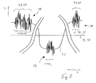
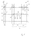
- the electric circuit 2 comprises an electric current source 4 with two terminals 5, 6, wherein one of the terminals 6 is electrically connected to ground. This terminal 6 is electrically connected via an electrical line 8 to a load 10.
- the consumer 10 is for example an electric servomotor, a lamp, or a sensor. With the consumer 10, a circuit breaker 14 is electrically connected via a further electrical line 12, wherein the circuit breaker 14 is connected to one of the terminals 5 of the power source 4.
- the circuit breaker 14 is designed to detect arcing faults 16 within the electrical circuit 2 and to interrupt the electrical circuit 2 by means of an interruption unit 17 after detection.
- the arc fault 16 occurs, for example, between the electrical lead 12 and another grounded element 18, for example, where insulation of the electrical lead 12 in a region 20 near the grounded element 18 is damaged.
- insulation of the electrical lead 12 in a region 20 near the grounded element 18 is damaged.
- either air or an electrically conductive liquid, such as in particular salt water, is located between the element 18 and the electrical line.
- the arc fault 16 may also occur along the electrical line 12.
- the current source 4 supplies an electric current 22 which is, for example, a sinusoidally running alternating current and has a rated current intensity.
- the electrical voltage 24 generated by the current source 4 has a similar course, wherein the nominal voltage value is, for example, 115 volts.
- the frequency of the current 22 and that of the voltage are each equal to a mains frequency 26, which is in particular 400 Hz.
- the circuit 2 is preferably realized in an aircraft. Conveniently, the terminal 6 is at the same electrical potential as the aircraft outer skin. It is also conceivable that if the circuit 2 is not realized in an aircraft, the terminal 6 and the element 18 are grounded.
- Fig. 2 shows a number of interference signals 28 within the time course of the electrical current 22.
- the course of the electrical current 22 is in this case, for example, not sinusoidal, but rather, in particular with regard to a comparatively simple explanation, rectangular. However, this does not limit the invention in any way.
- the frequency of each of the signals 28 is below an NF1 frequency 30, which is in particular 30 kHz.
- the electrical current 22 of the first of the interference signals 28 is above a NF1 threshold threshold 32, which is for example one third of the rated current.
- This noise signal 28 is referred to as an NF1 signal 34.
- the third of the Störsingale 28 meets the two criteria of an NF1 signal 34, after which the frequency of the interfering signal 28 is smaller than the NF1 frequency 30, and that the electric current 22 of the noise signal 28 is greater than the NF1 threshold 32.
- the first NF1 signal 34 is longer than the second NF1 signal 34, so the time length of the first NF1 signal 34 is greater than the time length of the second NF1 signal 34.
- the second of the interference signals 28 is not an NF1 signal 34, since, although the frequency of the interference signal 28 is smaller than the NF1 frequency 30, but also the electric current 22 during the duration of the second interference signal 28 is smaller than the NF1 limit threshold
- both the frequency of the individual interference signals 28 is less than an NF2 frequency 36, which is for example 400 Hz and in particular equal to the network frequency 26, and the electric current 22 is greater than an NF2 limit threshold 38, which is suitably equal to the rated current,
- the noise signals 28 are referred to as NF2 signals 40.
- the difference between the NF1 signal 34 and the NF2 signal 40 are therefore only the respective thresholds of the frequency as well as the electrical current 22 of the respective interference signals 28.
- the interference signal 28, which is referred to as NF2 signal 40 also as NF1 signal 34 denotes.
- the circuit breaker 6 analyzes the time course of the electrical current 22 and derives therefrom the frequency of the possible interference signals 28.
- This has the advantage, in comparison to, for example, a Fourier analysis of the course of the electric current 22, that the frequencies of the interference signals 28 can be analyzed within a certain time range, without having to expect any artifacts due to the temporal limitation of the time range.
- the computational effort can be reduced hereby, and there are likewise no restrictions on the length of the time range to be analyzed.
- Fig. 3 shows a further time course of the electric current 22.
- the electric current 22 comprises a number of interference signals 28, wherein the frequency of each of the interference signals 28 is smaller than an HF2 frequency 42.
- the HF2 frequency 42 is, for example, 3.3 MHz.
- Each of the interference signals 28, the respective length of which can vary, has a time interval 44 with respect to the respective previous interference signal 28. Is for a number temporally directly successive interference signals 28, the respective time interval 44 is smaller than an HF2 time 46, these interference signals 28 are combined to form an HF2 signal 48, if the number of such interference signals 28 exceeds an HF2 number 50 or the number of HF2 50 corresponds.
- the HF2 number 50 is in particular two.
- the first of the illustrated HF2 signals 48 comprises four interference signals 28 and the second of the illustrated HF2 signals 48 comprises three interference signals 28, in which case the most recent of the interference signals 28 has a comparatively long length.
- a number of HF2 signals 48 are shown.
- One point in each case represents an HF2 signal 48, wherein the length of the HF2 signals 48 can certainly vary.
- the period of time within which the HF2 signals 48 are measured is subdivided into individual time periods 52.
- the total time period that the circuit 2 is operated is subdivided into the periods 52.
- the length of each of the time periods 52 is equal to a cluster length 54, which is suitably 100 ⁇ s. All temporally related periods 52, within which at least one HF2 signal 48 has been registered, are combined into a cluster 56, if the number of such periods 52 is greater than or equal to an accumulation number 58.
- the accumulation number 58 is in particular equal to four.
- At least four contiguous periods 52 are combined into one of the aggregates 56 if at least one HF2 signal 48 has been measured in each of the respective time periods 52.
- the time interval between two directly successive HF2 signals may be both larger and smaller than the accumulation length 54, but not greater than twice the accumulation length 54.
- a plurality of HF2 signals 48 may be measured within one of the time periods 52 have been.
- the length of each of the clusters 56 is a multiple of the clump length 54.
- the circuit breaker 14 includes a microprocessor that can process the RF2 signals 48 only at a particular timing corresponding to the clump length 54.
- the circuit breaker 14 has an integration unit that counts all HF2 signals 48 of a single time period 52, for example, by means of a capacitor, and after expiration of the period 52, the measured number is forwarded to the microprocessor.
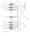
- a first method 60 for detecting the arc fault 16 is shown.
- the timing of the measurement of a number of clusters 56 within the circuit 2 is shown.
- Each stroke symbolizes an aggregate 56, wherein the length of each of the aggregates 56 may vary.
- the time course of the measurement of NF1 signals 34 and, in turn, that of the measurement of NF2 signals 40 is shown. Again, the length of the NF1 signals 34 varies, whereas, for example, no NF2 signal 40 is measured.
- a wait period 62 is started, which is in particular 100 ms.
- the number of clusters 56 leading to the start is equal to an accumulation value 64, which in particular is five.
- the time interval between each two of the clusters 56 is greater than or equal to a first clump time 66 and less than or equal to a second clump time 68.
- the clusters 56 are counted by means of a WET1 accumulation counter 70. At the beginning of the process 60, the WET1 accumulation counter 70 is set to zero (0).
- the count of the WET1 accumulation counter 70 is incremented by one (1) as soon as accumulation 56 within the electrical current 22 of the circuit 2 is detected.
- the WET1- Accumulation counter 70 again increased. If the time interval of two consecutive clusters 56 is less than or greater than the first clump time 66 and the second clump time 68, respectively, the WET1 clump counter is reset to zero (0).
- the waiting period 62 After reaching the accumulation value 64 by the count of the WET1 accumulation counter 70, the waiting period 62 is started. If an NF1 signal 34 is measured within the wait period 64, or two consecutive clusters 56 have a time interval less than a third cluster time 72, the wait period 62 is aborted and the WET1 accumulation counter 70 is zero (0). set.
- the third cluster time 72 is equal to 1.5ms. For example, clusters 56 having a time interval greater than the third clump time 72 have no effect on the wait period 62 and the WET1 clump count 70.
- the WET1 accumulation counter is incremented by one (1) as long as the aggregates 56 satisfy the above criteria. If no NF1 signal 34 is measured within the waiting period 62, and any accumulations 56 have a time interval which is greater than the third accumulation time 72, a message 74 of the fault arc 16 is output.
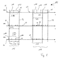
- Fig. 6 shows another method 76 for detecting the arc fault 16 according to Fig. 5 ,
- this method 76 the accumulations 56 present in the electric current 22 are counted.
- this method 76 only the clusters 56 are counted whose time interval is less than the third clumping time 72.
- a WET2 accumulation counter 78 is used here. At the beginning of the method 76, the count of the WET2 accumulation counter 78 is set to zero (0). Each time the WET2 accumulation counter 78 is zero (0), the count of the WET2 accumulation counter 78 is incremented by one (1) as soon as an accumulation 56 within the electrical current 22 of the circuit 2 is detected. For each additional identified aggregate 56 whose time distance from the temporally-directly accumulated aggregate 56 is less than the third accumulation time 72, the WET2 accumulation counter 78 is incremented by one (1). Once a cluster 56 has a time lag from the previous cluster 56 that is greater than the third cluster time 72, the WET2 cluster counter 78 is checked.
- the WET2 accumulation counter 78 is reset to zero (0). If the WET2 accumulation counter 78 exceeds the first WET2 threshold 80, an NF period 82 is started.
- the first WET2 threshold 80 is suitably six and the LF period 82 is 20ms in particular.
- an NF1 counter 84 becomes active.
- the NF1 counter 84 is set to zero (0), and increased by one (1) with each NF1 signal 34 measured within the LF period 82. If the NF1 counter 84 exceeds a second WET2 limit value 86, the message 74 of the disturbance arc 16 is output and, in particular, the LF period 82 is ended.
- the second WET2 threshold 86 is equal to three.
- the NF1 counter 84 and the WET2 accumulation counter 78 are set to zero (0) and the method 76 is restarted.
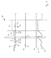
- FIG Fig. 7 Another method 88 for detecting the arc fault 16 is shown in FIG Fig. 7 shown.
- the time course of the measurement of a number of the HF2 signals 48 within the circuit 2 is shown. Each bar symbolizes one of the HF2 signals 48, wherein the length of each of the HF2 signals 48 may vary.
- the time course of the measurement of the NF1 signals 34 and below the time course of the measurement of NF2 signals 40 is shown. Again, the length of the NF1 signals 34 varies, whereas, for example, no NF2 signal 40 is measured.
- the RF2 signal 48 which starts the serial period 90 counts to the serial period 90 as well as to the first measurement phase 92 and is only shown slightly earlier in time for clarification.
- any HF2 signals 48 present in the electric current 22 are counted.
- the third break time period 94 is 200 ms and the fourth break time period 96 is 300 ⁇ s, for example.
- both the first measuring phase 92 and the serial period 90 are interrupted.
- the first measurement phase 92 and the serial period 90 are aborted if no further HF2 signal is measured for the third abort time period 94 after the last-time HF2 signal 48. This is the case, for example, according to the second of the illustrated HF2 signals 48.
- the first measuring phase 92 If, within the first measuring phase 92, a number of HF2 signals 48 including the HF2 signal 48 causing the start of the serial period 90 are counted, which number is equal to a first serial number 98, the first measuring phase 92 is ended and a holding period 100 started.
- the first serial number 98 is six, for example.
- any measured HF2 signals 48 are not considered within the hold period 100. This means that neither their number nor their respective length or the time interval between two HF2 signals 48 have any effect on the holding period 100.
- the hold period 100 is suitably between 30ms and 220ms long.
- the length of the holding period 100 depends on the size of the electrical current 22 and in particular on its rated current. For example, with a comparatively large rated current, the holding period 100 is greater than with a comparatively small rated current.
- the length of the holding period 100 during operation of the electrical circuit 2 is variable.
- the holding period 100 is followed directly by a second measuring phase 102.
- the second measuring phase 102 comparable to the first measuring phase 98, those HF2 signals 48 are counted, the time interval of which lies between the third interruption period 94 and the fourth interruption period 96 relative to the respective directly preceding HF2 signal 48 , Likewise, the second measurement phase 102 and the serial period 90 are also aborted if, within the second measurement phase 102, the time interval between two directly successive HF2 signals 48 is greater than the third abort time period 94.
- the second measurement phase 102 is ended if, within the second measurement phase 102, the number of HF2 signals 48 counted as described above corresponds to a second serial number 104.
- the second serial number 104 is equal to twelve.
- the serial period 90 is also ended.
- the NF1 signals 34 counted within the entire serial period 90 are checked whose time interval is between a fifth abort time interval 106 and a sixth abort time interval 108.
- the fifth abort time period 106 is advantageously equal to 8.3 ms and the sixth abort time period 108 is expediently 200 ms. If the number of such NF1 signals 34 is greater than a third serial number 110, the fault arc 16 is reported.
- the third serial number 110 is six.
- the message 74 of the fault arc is also output if the number of such NF1 signals 34 is equal to the third serial number 110, and after the last of such NF1 signals 34 for at least a period greater than or equal to the fifth abort Time period 106, no further NF1 signal 34 in the electric current 22 has been measured.
- the two first NF1 signals 34 of the second serial period 90 have a time interval which is smaller than the fifth abort time interval 106, and therefore these two NF1 signals 34 are not taken into account during the check.
- the respective time interval of all other NF1 signals 34 of the second serial period 90 lies between the fifth interruption period 106 and the sixth interruption period 108.
- Any NF1 signals 34 additionally measured before or after such NF1 signals 34 within the serial period 90 preferably have no effect on the message 74 of the fault arc 16.
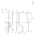
- Fig. 8 shows another method 112 for detecting the arc fault 16 according to Figure 7 , As soon as an NF2 signal 40 whose length is greater than an NF2 limit length 114 is measured outside of a parallel period 116, the parallel period 116 is started. Here too counts - comparable to the in Fig. 7 illustrated method 88 - the NF2 signal 40 starting the parallel period 116 to the parallel period 116.
- the NF2 limit length 114 is equal to 200 ⁇ s, for example.
- the parallel period 116 all NF2 signals 40 whose length is greater than or equal to the NF2 limit length 114 are counted, and the parallel period 116 is aborted if one of the lengths of the NF2 signals 40 is less than the NF2 limit length 114 .
- the parallel period 116 is also aborted if no NF2 signal 40 is measured for a second abort period 118 within the parallel period 116.
- the second abort time period 118 equal to 500ms.
- an electrical voltage 24 which during the parallel period 116 is less than a termination voltage for a first termination period results in abort of the parallel period 116.
- the termination voltage is equal to 15V and the first termination period is in particular 3,2ms.
- the HF2 signals 48 are counted within the parallel period 116, the time interval to the respective time directly preceding the HF2 signal 48 is greater than or equal to a first arc fault period 120, which is in particular 500 ⁇ s. It is further checked whether one of the distances is greater than a second arc fault period 122. If so, and both the number of total HF2 signals 48 measured within a third arc fault period 124 is greater than or equal to a first arc fault count 126, and the number of NF2 values measured within the third arc fault period 124. Signals 40 is greater than or equal to a second arc number 128 and less than or equal to a third arc number 130, the arc is 16 reported.
- the third arc interval 124 begins with the parallel period 116 and is suitably 25 ms long.
- the first arc number 126 is three
- the second arc number 128 is more preferably three
- the third arc number 130 is preferably seven.
- all NF2 signals 40 have a time length that is greater than the NF2 limit length 114, and with the time-first NF2 signal 40, the first of the two parallel period 116 shown is started.
- this parallel period 116 including the NF2 signal 40, which triggers the start of this parallel period 116, three NF2 signals 40 are measured, this number corresponding to the second number of arcing faults 128.
- three HF2 signals 48 are also measured, this number being equal to the first arc number 126.
- the distance between the first and second of the HF2 signals 48 is greater than the first arc fault period 120, and the distance between the second and third of the HF2 signals 48 is greater than the second arc fault period 122. Since three NF2 signals 40 were measured within the third arc fault period 124, after the time last of the three HF2 signals 48, both the parallel period 116 is terminated and the arc fault 16 is reported.
- the fourth of the NF2 signals 40 starts the second of the parallel periods 116 shown.
- the time sequence of the HF2 signals 48 measured within the second of the parallel periods 116 is, for example, equal to the time sequence of the HF2 signals 48 measured within the first of the parallel periods 116.
- nine NF2 signals 40 are measured. This number is larger than the third arc number 130, and therefore, after the third of the Hf2 signals 48 measured within the second of the parallel periods 116, the second parallel period 116 is not completed.
- the fourth number of arc faults 132 is four, and therefore, after measuring the fourth HF2 signal 48 of the second parallel period 116, the message 74 of the fault arc 16 is output, the time interval of this HF2 signal 48 being directly temporally preceding the HF2 signal 48 is greater than or equal to the first arc fault period 120.
- this method 112 alternates with at least one other, preferably all, of the above methods 60, 76, 88.
- the further method is interrupted when one of the NF 2 signal 40 is measured whose length is greater than the NF 2 limit length 114.
- the further process is halted, which means that with the exception of the signals required for the method 112, namely the HF2 signals 48 and the NF2 signals 40, no further signal such as the NF1 signals 34 or the clusters 56 be further processed.
- the HF2 signals 48 are only considered insofar as they contribute to the method 112.
- Fig. 9 the time course of the electrical voltage 24 is shown, which is substantially sinusoidal. Due to the temporal periodicity of the electrical voltage 24 in normal operation this regularly exceeds a limit value, which is referred to as SPG voltage 134.
- the SPG voltage 134 is less than the rated voltage and is preferably 90V.
- the period of time during which the electrical voltage 24 is greater than the SPG voltage 134 is referred to as a wedding margin 136.
- the length 138 of all wedding spans 136 is substantially the same and constant as well as dependent on the network frequency 26. For example, the length 138 in normal operation is 600 ⁇ s.
- the time interval between the individual wedding spans 136 is substantially the same and constant and dependent on the network frequency 26.
- the time interval in normal operation is reciprocal to the network frequency 26 - ie 2.5ms - minus the length 138 of the wedding span 136. In particular, the temporal Distance 1,9ms.
- the course of the electrical voltage 24 deviates from the sinusoidal shape.
- such influences on the electrical voltage 24 have the consequence that the frequency of the electrical voltage 24 is disturbed, ie that the frequency is not constant, or that the maximum of the electrical voltage 24 for a period of time greater than twice the reciprocal of the mains frequency 26 is less than the rated voltage.
- SPG error 142 a problem of the electrical voltage 24 is identified is referred to as SPG error 142.
- the third SPG period is suitably 100 ⁇ s and the second SPG period is in particular 6.4 ms.
- At least one of the above methods 76, 88 is aborted and not restarted for a period of time having a length of a first SPG period.
- neither the WET2 accumulation counter 78 nor the NF1 counter 84 is changed within the first SPG period after the SPG error 140.
- the method or methods 76, 88 are restarted, resulting in particular in resetting the respective counters to zero (0).
- the SPG period is suitably 1s.
Abstract
Die Erfindung betrifft Verfahren (60,76, 88, 112) zur Erkennung von Störlichtbögen (16) innerhalb eines elektrischen Stromkreises (2) sowie einen Schutzschalter(14).The invention relates to methods (60, 76, 88, 112) for detecting arcing faults (16) within an electrical circuit (2) and to a circuit breaker (14).
Description
Die Erfindung betrifft Verfahren zur Erkennung von Störlichtbögen innerhalb eines eine Netzfrequenz, einen elektrischen Strom und eine elektrische Spannung aufweisenden Stromkreises sowie einen danach arbeitenden Schutzschalter.The invention relates to methods for detecting arcing within a circuit having a mains frequency, an electrical current and an electrical voltage circuit and a protective switch operating thereafter.
Innerhalb eines elektrischen Stromkreises können sogenannten Störlichtbögen auftreten. Störlichtbögen sind unerwünschte Ströme zwischen zumindest einem Element des Stromkreises und einem weiteren Element, wobei zwischen den beiden Elementen eine Potentialdifferenz existiert. Üblicherweise stehen die beiden Elemente nicht in direktem elektrischem Kontakt, sondern meist befindet sich zwischen diesen eine Isolierung. Ist die Isolierung defekt, indem diese beispielsweise aufgrund von Alterung porös geworden ist oder infolge mechanischen Einwirkens zumindest teilweise entfernt ist, so ist es möglich, dass zwischen den beiden Elementen ein weiterer Stoff eindringt und sich dort anlagert. Dieser Stoff kann flüssig, beispielsweise Wasser, oder gasförmig, insbesondere Luft, sein. Aufgrund der fehlenden Isolationswirkung ist es bei den innerhalb des Stromkreises auftretenden Strömen und/oder Spannungen möglich, dass ein elektrischer Überschlag, der Störlichtbogen, zwischen den beiden Elementen auftritt.Within an electrical circuit so-called arcing faults can occur. Fault arcs are unwanted currents between at least one element of the circuit and another element, wherein between the two elements a potential difference exists. Usually, the two elements are not in direct electrical contact, but usually there is an insulation between them. If the insulation is defective, for example because it has become porous due to aging or at least partially removed as a result of mechanical action, then it is possible for another substance to penetrate between the two elements and accumulate there. This substance can be liquid, for example water, or gaseous, in particular air. Due to the lack of insulation effect, it is possible for the currents and / or voltages occurring within the circuit that an electrical flashover, the arc fault, occurs between the two elements.
Es werden drei verschiedene Typen von Störlichtbögen, auch Arc genannt, unterschieden. Bei dem sogenannten Wet-Arc ist der eindringende Stoff eine Flüssigkeit, meist Wasser, die eine hohe elektrische Leitfähigkeit aufweist. Das weitere Element ist meist elektrisch mit Masse verbunden oder geerdet und nicht zwangsläufig ein Bestandteil des Stromkreises. Aufgrund der hohen elektrischen Leitfähigkeit und somit aufgrund des geringen elektrischen Widerstandes der Flüssigkeit können zwischen den beiden Elementen vergleichsweise hohe Ströme auftreten, was zu einer Beeinträchtigung etwaiger Verbraucher des elektrischen Stromkreises führen kann.There are three different types of arcs, also called arc, a distinction. In the so-called wet-arc of the penetrating substance is a liquid, usually water, which has a high electrical conductivity. The further element is usually electrically connected to ground or grounded and not necessarily a part of the circuit. Due to the high electrical conductivity and thus due to the low electrical resistance of the liquid comparatively high currents can occur between the two elements, which can lead to an impairment of any consumer of the electrical circuit.
Bei einem sogenannten Parallel-Arc ist der eindringende Stoff ein Gas, insbesondere Luft. Das weitere Element ist meist elektrisch mit Masse verbunden oder geerdet und nicht zwangsläufig ein Bestandteil des Stromkreises. Aufgrund des elektrischen Feldes zwischen den beiden Elementen wird das Gas ionisiert und es kann ein elektrischer Strom zwischen den beiden Elementen fließen. Schon bei Potentialdifferenzen von ca. 30 Volt ist ein derartiger Überschlag möglich. Aufgrund der vergleichsweise schlechten elektrischen Leitfähigkeit des ionisierten Gases ist der elektrische Strom zwischen den beiden Elementen nicht konstant, sondern vielmehr hochfrequent, was zu einer hohen thermischen Aufladung der beiden Elemente, des Stoffes und/oder deren jeweiliger Umgebung führt. Die hierbei auftretenden Temperaturen erreichen bis zu einige tausend Grad, so dass eine weitere Beschädigung der Isolation, der Elemente und/oder der jeweiligen Umgebung nicht ausgeschlossen ist.In a so-called parallel arc, the penetrating substance is a gas, in particular air. The further element is usually electrically connected to ground or grounded and not necessarily a part of the circuit. Due to the electric field between the two elements, the gas is ionized and an electric current can flow between the two elements. Even at potential differences of about 30 volts, such a rollover is possible. Due to the comparatively poor electrical conductivity of the ionized gas, the electric current between the two elements is not constant, but rather high-frequency, which leads to a high thermal charge of the two elements, the substance and / or their respective environment. The temperatures occurring here reach up to a few thousand degrees, so that further damage to the insulation, the elements and / or the respective environment is not excluded.
Insbesondere bei Flugzeugen ist diese Gefahr besonders groß, da üblicherweise verlegte Kabel zu Kabelbäumen zusammen gefasst werden. Falls das erste Element eines dieser Kabel ist, kann ein auftretender Störbogen den gesamten Kabelbaum schädigen und somit die Betriebssicherheit des Flugzeuges gefährden. Weiterhin ist es möglich, dass den Kabelbaum umgebende Elemente oder der Kabelbaum selbst in Brand geraten.Especially for aircraft, this risk is particularly great because usually routed cables are combined into harnesses together. If the first element is one of these cables, an occurring fault arc can damage the entire cable harness and thus jeopardize the operational safety of the aircraft. Furthermore, it is possible that the wiring harness surrounding elements or the wiring harness itself caught fire.
Ein weiterer Störlichtbogen-Typ ist der Seriell-Arc. Bei diesem ist das weitere Element das erste Element selbst, welches meist ein Kabel ist. Der Überschlag erfolgt entlang des Kabels, wobei der eingedrungene Stoff meist Luft ist, die durch eine porös gewordenen Isolierung in elektrischem Kontakt zu dem Kabel steht. Der Mechanismus der zu diesem Störlichtbogen führt ist vergleichbar mit dem Parallel-Arc und ebenso auch dessen Auswirkungen.Another arc fault type is the serial arc. In this case, the further element is the first element itself, which is usually a cable. The rollover occurs along the cable, wherein the penetrated material is usually air which is in electrical contact with the cable through a porous insulation. The mechanism that leads to this arc is similar to the parallel arc and its effects.
Aus der
Hierbei werden die zwischen zwei aufeinanderfolgenden Störsignalen gebildeten Zeiträume auf deren Länge, deren Beginn oder deren Ende hin analysiert. Sofern zwei im Abstand einer Netzfrequenz aufeinanderfolgende Zeiträume vorliegen, wird ein Zähler erhöht. Falls eine bestimmte Anzahl von regelmäßigen störsignalfreien Zeiträumen vorliegt ist ein Störlichtbogen erkannt. Anstatt dessen können nach Registrierung der bestimmten Anzahl von Störlichtbogen weiterhin die Zeiträume gezählt werden. Falls ein Zeitraum unregelmäßig ist, wird der Zähler um einen vorgegebenen Wert reduziert. Falls der Zähler eine bestimmte zweite Anzahl erreicht hat, wird ein Störlichtbogen gemeldet.In this case, the time periods formed between two consecutive interference signals are analyzed for their length, their beginning or their end. If there are two consecutive periods at intervals of one network frequency, a counter is incremented. If a certain number of regular no-interference periods is present, an arc fault is detected. Instead, after registration of the determined number of fault arcs, the time periods may continue to be counted. If a period is irregular, the counter is reduced by a predetermined value. If the meter has reached a certain second number, an arc is reported.
Bei dem zweiten Verfahren werden Störsignale auf deren Unregelmäßigkeiten hin überprüft. Falls sich aufeinanderfolgende Störsignale in deren Position relativ zur Netzfrequenz und deren Länge unterscheiden, ist ein Störlichtbögen erkannt. Zusätzlich wird der Anstieg des jeweiligen Störsignals analysiert, da der Erfinder erkannt hat, dass Störsignale, die von Störlichtbögen hervorgerufen werden, einen zeitlich steileren Anstieg aufweisen als etwaige Störsignale, die von Halbleiterschaltelementen innerhalb des Stromkreises bedingt sind.In the second method, interference signals are checked for their irregularities. If successive spurious signals differ in their position relative to the mains frequency and their length, an arcing fault is detected. In addition, the rise of the respective noise signal is analyzed, because the inventor has recognized that noise caused by arcs of arc have a temporally steeper slope than any noise caused by semiconductor switching elements within the circuit.
Die vorgestellten Verfahren werden von einem Schutzschalter, einem Überwachungselement und einem tragbaren Analysegerät ausgeführt.The presented methods are performed by a circuit breaker, a monitoring element and a portable analyzer.
In der
Aus der
Der Erfindung liegt die Aufgabe zugrunde, sowohl ein besonders geeignetes Verfahren zur Erkennung von Störlichtbögen innerhalb eines eine Netzfrequenz, einen elektrischen Strom und eine elektrische Spannung aufweisenden Stromkreises als auch einen besonderes geeigneten Schutzschalter anzugeben.The invention has for its object to provide both a particularly suitable method for detecting arcing within a circuit having a mains frequency, an electrical current and an electrical voltage circuit as well as a special suitable circuit breaker.
Die das Verfahren betreffende Aufgabe wird erfindungsgemäß gelöst durch die Merkmale des Anspruchs 1. Eine vorteilhafte Weiterbildung ist Gegenstand des hierauf rückbezogenen Unteranspruchs.The object relating to the method is achieved according to the invention by the features of claim 1. An advantageous further development is the subject of the dependent claim dependent thereon.
Im Folgenden wird unter einem Störsignal eine Abweichung eines Istwertes eines elektrischen Stromes von einem zugehörigen Sollwert verstanden. Die Abweichung weist eine Zeitdauer und während dieser eine bestimmte Frequenz auf, wobei die Abweichung auch eine Anzahl von Frequenzen oder ein Frequenzband während dieser Zeitspanne aufweisen kann. Nachfolgend wird davon ausgegangen, dass ein Störsignal lediglich eine Frequenz umfasst, wobei jedoch das Störsignal auch mehrere Frequenzen umfassen kann.In the following, an interference signal is understood as meaning a deviation of an actual value of an electrical current from an associated desired value. The deviation has a duration and during this a certain frequency, wherein the deviation may also have a number of frequencies or a frequency band during this period. It will be assumed below that an interference signal comprises only one frequency, but that the interference signal may also comprise a plurality of frequencies.
Befinden sich die Frequenz der Abweichungen unterhalb einer NF1-Frequenz, wobei währenddessen der elektrische Strom oberhalb einer NF1-Grenzschwelle liegt, so wird dieses Störsignal als NF1-Signal bezeichnet. Unter einem NF2-Signal wird ein Störsignal verstanden, dessen Frequenz kleiner als eine NF2-Frequenz ist, während zeitgleich die Stromstärke größer als eine NF2-Grenzschwelle ist. Als Länge des NF1- Signals und als Länge des NF2-Signals wird die Zeitdauer bezeichnet, die das Störsignal mit den jeweiligen obigen Parametern andauert.If the frequency of the deviations is below an NF1 frequency, during which the electrical current is above a NF1 threshold, then this interference signal is referred to as NF1 signal. An NF2 signal is an interference signal whose frequency is less than an NF2 frequency, while at the same time the current is greater than an NF2 threshold. The length of the NF1 signal and the length of the NF2 signal is the duration of the duration of the interference signal with the respective parameters above.
Als ein HF2-Signal wird eine Anzahl von Störsignalen, die eine Frequenz unterhalb einer HF2-Frequenz aufweisen, bezeichnet. Hierbei ist der zeitliche Abstand zweier aufeinanderfolgender Störsignale kleiner als eine HF2-Zeit, und die Anzahl der Störsignale ist größer als eine HF2-Anzahl. Tritt ein weiteres Störsignal mit einer Frequenz unterhalb der HF2-Frequenz innerhalb einer Zeitspanne, die kleiner als die HF2-Zeit ist, nach dem letzten Störsignal eines HF2-Signals auf, so wird das weitere Störsignal zu dem HF2-Signal gezählt und die Länge des HF2-Signals entsprechend verlängert. Dies führt unter anderem dazu, dass der zeitliche Abstand zweier aufeinanderfolgender HF2-Signale größer als die HF2-Zeit ist.As an HF2 signal, a number of interfering signals having a frequency below an HF2 frequency is designated. Here, the time interval between two consecutive interference signals is smaller than an HF2 time, and the number of interference signals is greater than an HF2 number. If another interference signal having a frequency below the HF2 frequency occurs within a time period which is shorter than the HF2 time after the last interference signal of an HF2 signal, the further interference signal is counted to the HF2 signal and the length of the HF2 signal HF2 signal extended accordingly. Among other things, this leads to the fact that the time interval between two successive HF2 signals is greater than the HF2 time.
Folgen eine Anzahl von Zeiträumen, innerhalb derer mindestens jeweils ein HF2-Signal liegt, direkt aufeinander, so wird dies als eine Anhäufung bezeichnet. Die Länge jeder der Zeiträume beträgt hierbei einer Anhäufungs-Länge. Die Anzahl der Anhäufungen ist größer oder gleich einer Anhäufungs-Anzahl. Tritt in einem weiteren Zeitraum mit einer zeitlichen Länge, die der Anhäufungs-Länge entspricht, nach dem letzten ein HF2-Signal enthaltenden Zeitraum einer Anhäufung ein weiteres HF2-Signal auf, so wird der das weitere HF2-Signal enthaltende Zeitraum zu der Anhäufung gezählt und die Länge der Anhäufung entsprechend verlängert.If a number of periods within which there is at least one HF2 signal in each case follow one another directly, this is referred to as an accumulation. The length of each of the Periods here is an accumulation length. The number of clusters is greater than or equal to an accumulation number. Occurs in another period with a time length corresponding to the accumulation length, after the last HF2 signal-containing period of an accumulation another HF2 signal, the period containing the further HF2 signal is counted to the accumulation and lengthened the accumulation accordingly.
Es ist insbesondere möglich, dass ein Störsignal zu einer Anzahl der oben genannten Signale und/oder der Anhäufung beiträgt. Weiterhin wird im Folgenden davon ausgegangen, dass, falls ein Signal einen Zeitraum, eine Zeitspanne, eine zeitliche Phase oder eine zeitliche Periode startet, oder der Zeitraum, die Zeitspanne, die zeitliche Phase oder die zeitliche Periode mittels des Signals gestartet wird, das Signal zu dem Zeitraum, der Zeitspanne, der zeitlichen Phase oder der zeitlichen Periode gezählt wird, also innerhalb des Zeitraums, der Zeitspanne, der zeitlichen Phase oder der zeitlichen Periode liegt.In particular, it is possible for an interference signal to contribute to a number of the above-mentioned signals and / or the accumulation. Furthermore, it is assumed below that, if a signal starts a period, a time period, a time phase or a time period, or the period, the time period, the time phase or the time period is started by means of the signal, the signal the period, the time period, the time phase or the time period is counted, ie within the period, the time period, the time phase or the time period.
Das Verfahren nutz einen nachfolgend als WET1-Anhäufungszähler bezeichneten Zähler. Bei dem Start des Verfahrens wird der WET1-Anhäufungszähler auf null (0) gesetzt. Jedes Mal, wenn der WET1-Anhäufungszähler null (0) beträgt, wird, falls eine Anhäufung identifiziert wird, der WET1-Anhäufungszähler um eins (1) erhöht. Mit anderen Worten wird der Zählerstand des WET1-Anhäufungszählers um eins (1) erhöht, sobald eine Anhäufung innerhalb des elektrischen Stroms des Stromkreises erkannt wird. Mit jeder weiteren identifizierten Anhäufung wird der Zählerstand des WET1-Anhäufungszählers um eins (1) erhöht, solange der zeitliche Abstand zweier aufeinanderfolgender Anhäufungen größer als eine erste Anhäufungs-Zeit und kleiner als eine zweite Anhäufungs-Zeit ist. Ist dies nicht der Fall, so wird der WET1-Anhäufungszähler auf null (0) zurückgesetzt.The method uses a counter referred to below as a WET1 accumulation counter. At the start of the process, the WET1 accumulation counter is set to zero (0). Each time the WET1 accumulation count is zero (0), if an accumulation is identified, the WET1 accumulation counter is incremented by one (1). In other words, the count of the WET1 accumulation counter is incremented by one (1) as soon as an accumulation within the electrical current of the circuit is detected. With each further accumulation identified, the count of the WET1 accumulation counter is incremented by one (1) as long as the time interval between two successive accumulations is greater than a first accumulation time and less than a second accumulation time. If this is not the case, the WET1 accumulation counter is reset to zero (0).
Erreicht der Zählerstand des WET1-Anhäufungszählers einen Anhäufungswert, so wird eine Warteperiode gestartet und insbesondere während der Warteperiode der Zählerstand des WET1-Anhäufungszählers nicht weiter verändert. Falls während der Warteperiode zwei aufeinanderfolgende Anhäufungen einen zeitlichen Abstand aufweisen, der kleiner als eine dritte Anhäufungs-Zeit ist, so wird die Warteperiode abgebrochen und der WET1-Anhäufungszähler auf null (0) gesetzt. Ebenfalls führt mindestens ein NF1-Signal, vorzugsweise ein, zwei, oder drei NF1-Signale, zu einem Abbruch der Warteperiode und einem Zurücksetzten des WET1-Anhäufungszählers auf null (0). Endet die Warteperiode regulär, wird also die Warteperiode nicht abgebrochen, so wird nach Ablauf der Warteperiode ein Störlichtbogen gemeldet.When the count of the WET1 accumulation counter reaches an accumulation value, a waiting period is started and, in particular, during the waiting period, the count of the WET1 accumulation counter is not further changed. If, during the waiting period, two consecutive clusters have a time interval which is less than a third clumping time, the waiting period is aborted and the WET1 accumulation counter is set to zero (0). Also, at least one NF1 signal, preferably one, two, or three NF1 signals, results in aborting the wait period and resetting the WET1 accumulation counter to zero (0). If the waiting period ends in a regular manner, ie if the waiting period is not aborted, an arc will be reported after the waiting period has expired.
Falls ein NF2-Signal, das länger als eine NF2-Grenzlänge andauert, innerhalb des elektrischen Stroms gemessen wird, wird geeigneterweise der WET1-Anhäufungszähler auf null (0) gesetzt und für einen Parallelzeitraum auf null (0) belassen. Der WET1-Anhäufungszähler wird also während des Parallelzeitraums nicht um eins (1) erhöht, falls währenddessen eine Anhäufung identifiziert wird. In dem Fall, dass ein derartiges NF2-Signal während der Warteperiode gemessen wird, wird diese abgebrochen, der WET1-Anhäufungszähler auf null (0) gesetzt und ebenfalls für den Parallelzeitraum auf null (0) belassen.If an NF2 signal lasting longer than an NF2 limit length is measured within the electrical current, suitably the WET1 accumulation counter is set to zero (0) and left at zero (0) for a parallel period. Thus, the WET1 accumulation counter is not incremented by one (1) during the parallel period if an accumulation is identified during that time. In the event that such an NF2 signal is measured during the waiting period, it is aborted, the WET1 accumulation counter is set to zero (0) and also left at zero (0) for the parallel period.
Der Parallelzeitraum wird jedes Mal dann beendet, falls während des Parallelzeitraums ein NF2-Signal gemessen wird, dessen Länge kürzer als die NF2-Grenzlänge ist. Ebenfalls wird jedes Mal der Parallelzeitraum abgebrochen, wenn die elektrische Spannung für eine erste Abbruch-Zeitspanne kleiner einer Abbruch-Spannung war, oder wenn für einen Zeitraum, der die Länge einer zweiten Abbruch-Zeitspanne aufweist, kein NF2-Signal gemessen wurde.The parallel period is terminated each time during the parallel period when an NF2 signal is measured whose length is shorter than the NF2 limit length. Also, each time the parallel period is aborted when the voltage for a first abort period was less than an abort voltage, or when no NF2 signal was measured for a period having the length of a second abort period.
Dahingegen wird ein Störlichtbogen gemeldet, falls eine Anzahl von HF2-Signalen innerhalb des Parallelzeitraums gemessen wurde, wobei der zeitliche Abstand jeweils zweier aufeinanderfolgender HF2-Signale größer oder gleich einer ersten Störlichtbogen-Zeitspanne ist. Einer der Abstände zwischen zweien der HF2-Signale ist hierbei größer oder gleich einer zweiten Störlichtbogen-Zeitspanne, wobei diese größer oder gleich der ersten Störlichtbogen-Zeitspanne ist.On the other hand, an arc fault is reported if a number of HF2 signals were measured within the parallel period, wherein the time interval of each two successive HF2 signals is greater than or equal to a first arc fault period. One of the distances between two of the HF2 signals is greater than or equal to a second arc fault period, which is greater than or equal to the first arc fault period.
Die Anzahl der HF2-Signale, die zu einem gemeldeten Störlichtbogen führen, hängt von etwaigen NF2-Signalen innerhalb einer dritten Störlichtbogen-Zeitspanne ab. Die dritte Störlichtbogen-Zeitspanne bezeichnet den zeitlich ersten Abschnitt des Parallelzeitraums. Wird innerhalb der dritten Störlichtbogen-Zeitspanne eine Anzahl von NF2-Signalen gemessen, die zwischen einschließlich einer zweiten Störlichtbogen-Anzahl und einer dritten Störlichtbogen-Anzahl liegt, so ist die Anzahl der zu der Meldung führenden HF2-Signale größer oder gleich einer ersten Störlichtbogen-Anzahl. Insbesondere ist die dritte Störlichtbogen-Anzahl größer als die zweite Störlichtbogen-Anzahl. Falls innerhalb der dritten Störlichtbogen-Zeitspanne eine Anzahl von NF2-Signale gemessen wurde, die größer als die dritte Störlichtbogen-Anzahl ist, so wird erst nach dem Messen von einer Anzahl, die größer oder gleich einer vierten Störlichtbogen-Anzahl ist, von HF2-Signalen der Störlichtbogen gemeldet.The number of HF2 signals resulting in a reported fault arc depends on any NF2 signals within a third arc fault period. The third arc fault period denotes the temporally first portion of the parallel period. If a number of NF2 signals is measured within the third arc fault period, which is between a second arc fault number and a third arc fault number, the number of HF2 signals leading to the message is greater than or equal to a first arc fault. Number. In particular, the third number of arcing faults is greater than the second number of arcing faults. If a number of NF2 signals greater than the third number of arcing faults has been measured within the third arc fault period, HF2 will not be measured until a number greater than or equal to a fourth number of arcing faults has been measured. Signals of the arc fault reported.
Die das Verfahren betreffende Aufgabe wird ebenfalls gelöst durch die Merkmale des unabhängigen Anspruchs 3. Vorteilhafte Weiterbildungen und Ausgestaltungen sind Gegenstand der hierauf bezogenen Unteransprüche.The object relating to the method is likewise achieved by the features of independent claim 3. Advantageous developments and refinements are the subject matter of the subclaims related thereto.
Das Verfahren nutz einen nachfolgend als WET2-Anhäufungszähler bezeichneten Zähler und einen NF1-Zähler. Mit dem Start des Verfahrens werden der WET2-Anhäufungszähler und der NF1-Zähler jeweils auf null (0) gesetzt. Wenn der WET2-Anhäufungszähler null (0) beträgt und eine Anhäufung identifiziert wird, wird der WET2-Anhäufungszähler um eins (1) erhöht. Mit anderen Worten wird der Zählerstand des WET2-Anhäufungszählers um eins (1) erhöht, sobald eine Anhäufung innerhalb des elektrischen Stroms des Stromkreises erkannt wird. Mit jeder weiteren identifizierten Anhäufung wird der Zählerstand des WET2-Anhäufungszählers um eins (1) erhöht, solange der zeitliche Abstand zweier aufeinanderfolgender Anhäufungen kleiner der dritten Anhäufungs-Zeit ist. Wird nach einer der Anhäufungen für einen Zeitraum, der größer als eine dritte Anhäufungs-Zeit ist, keine Anhäufung gemessen, so wird entweder der WET2-Anhäufungszähler auf null (0) gesetzt, falls der Zählerstand des WET2-Anhäufungszähler kleiner oder gleich einem ersten WET2-Grenzwertes ist, oder es wird eine NF-Periode gestartet, falls der Zählerstand des WET2-Anhäufungszähler größer als der erste WET2-Grenzwert ist. Insbesondere wird der Zählerstand des WET2- Anhäufungszählers innerhalb der NF-Periode nicht weiter erhöht.The method uses a counter referred to below as a WET2 accumulation counter and an NF1 counter. With the start of the procedure, the WET2 accumulation counter and the NF1 counter are each set to zero (0). If the WET2 accumulation count is zero (0) and an accumulation is identified, the WET2 accumulation counter is incremented by one (1). In other words, the count of the WET2 accumulation counter is incremented by one (1) as soon as an accumulation within the electrical current of the circuit is detected. With each further accumulation identified, the count of the WET2 accumulation counter is incremented by one (1) as long as the time interval of two successive accumulations is less than the third accumulation time. If no accumulation is measured after one of the clusters for a period greater than a third accumulation time, either the WET2 accumulation counter is set to zero (0) if the count of the WET2 accumulation counter is less than or equal to a first WET2 Limit value, or an LF period is started if the count of the WET2 accumulation counter is greater than the first WET2 limit. In particular, the count of the WET2 accumulation counter is not further increased within the NF period.
Jedes NF1-Signal, das innerhalb der NF-Periode gemessen wird, führt zu einer Erhöhung des NF1-Zählers um eins (1). Überschreitet der Zählerstand des NF1-Zählers einen WET2-Grenzwert, so wird ein Störlichtbogen gemeldet. Ist nach Ablauf der NF-Periode der Zählerstand kleiner als der WET2-Grenzwert, werden der WET2-Anhäufungszähler und der NF1-Zähler jeweils auf null (0) gesetzt.Any NF1 signal measured within the LF period will increase the NF1 counter by one (1). If the counter reading of the NF1 counter exceeds a WET2 limit value, an arc fault is signaled. If, after the LF period, the count is less than the WET2 limit, the WET2 accumulation counter and the NF1 counter are each set to zero (0).
In einer zweckmäßigen Ausführungsform der Erfindung wird die elektrische Spannung überwacht. Ist für einen Zeitraum, der länger als eine zweite SPG-Zeitspanne ist, die elektrische Spannung kleiner als eine SPG-Spannung, so werden der WET2-Anhäufungszähler und der NF1-Zähler auf null (0) gesetzt. Die SPG-Spannung ist hierbei vorteilhafterweise konstant, kann jedoch ebenso ein variabler Schwellwert unter- oder oberhalb einer Sollspannung sein. Die beiden Zähler werden ebenfalls zurückgesetzt, falls sich die Längen zweier aufeinanderfolgender Hochzeitspannen um mehr als eine dritte SPG-Zeitspanne unterscheiden. Als Hochzeitspannen wird die Zeitspanne bezeichnet, innerhalb derer die Spannung größer als die SPG-Spannung ist. Gegebenenfalls wird in beiden Fällen die NF-Periode abgebrochen, falls diese bereits begonnen hat. Sollten die beiden Zähler aufgrund der elektrischen Spannung auf null (0) gesetzt werden, so werden anschließend der WET2-Anhäufungszähler und der NF1-Zähler für eine erste SPG-Zeitspanne nicht verändert.In an advantageous embodiment of the invention, the electrical voltage is monitored. If, for a period of time longer than a second SPG period, the voltage is less than a SPG voltage, then the WET2 accumulation counter and the NF1 counter are set to zero (0). The SPG voltage is advantageously constant, but may also be a variable threshold below or above a nominal voltage. The two counters are also reset if the lengths of two consecutive wedding spans differ by more than a third SPG period. Marriages are the period of time during which the voltage is greater than the SPG voltage. If necessary, in both cases the NF period is aborted, if it has already started. If the two counters are set to zero (0) due to the electrical voltage, then the WET2 accumulation counter and the NF1 counter are not changed for a first SPG period.
Zweckmäßigerweise wird der WET2-Anhäufungszähler und der NF1-Zähler auf null (0) zurückgesetzt und während des sich daran anschließenden Parallelzeitraums nicht verändert, falls ein NF2-Signal gemessen wird, dessen Länge größer als die NF2-Grenzlänge ist. In Kombination dazu wird die NF-Periode abgebrochen, falls diese bereits begonnen hat.Conveniently, the WET2 accumulation counter and the NF1 counter are reset to zero (0) and not changed during the subsequent parallel period if an NF2 signal whose length is greater than the NF2 limit length is measured. In combination, the NF period is aborted if it has already started.
Ein Störlichtbogen wird gemeldet, falls innerhalb des Parallelzeitraums zwischen allen aufeinanderfolgenden HF2-Signalen der zeitliche Abstand größer oder gleich der ersten Störlichtbogen-Zeitspanne ist, wobei einer der Abstände größer oder gleich der zweiten Störlichtbogen-Zeitspanne ist. Hierbei ist die Anzahl der HF2-Signale, die zu der Meldung führt, abhängig von etwaigen NF2-Signalen, die innerhalb der dritten Störlichtbogen-Zeitspanne des Parallelzeitraums in dem elektrischen Strom gemessen werden. Ist die Anzahl der gemessenen NF2-Signale größer oder gleich der zweiten Störlichtbogen-Anzahl und kleiner oder gleich der dritten Störlichtbogen-Anzahl, so wird der Störlichtbogen gemeldet, falls eine Anzahl von HF2-Signalen innerhalb des Parallelzeitraums gemessen wurde, die mindestens der ersten Störlichtbogen-Anzahl entspricht. Ist die Anzahl der gemessenen NF2-Signale größer als die dritten Störlichtbogen-Anzahl, so wird erst nachdem eine Anzahl, die größer oder gleich der vierten Störlichtbogen-Anzahl ist, von HF2-Signalen der Störlichtbogen gemeldet.An arc fault is reported if within the parallel time interval between all consecutive RF2 signals the time interval is greater than or equal to the first arc fault time interval, one of the distances being greater than or equal to the second fault arc time period. Here, the number of HF2 signals leading to the message depends on any NF2 signals that occur within the third arc fault period of the parallel period in the electric current. If the number of measured NF2 signals is greater than or equal to the second number of arc faults and less than or equal to the third number of arc faults, the fault arc is reported if a number of HF2 signals were measured within the parallel period, which is at least the first arc fault Number corresponds. If the number of measured NF2 signals is greater than the third number of arcing faults, then the fault arc is reported by HF2 signals only after a number that is greater than or equal to the fourth number of arcing faults.
Der Parallelzeitraum wird beendet und kein Störlichtbogen gemeldet, falls während des Parallelzeitraums die Länge eines NF2-Signals kürzer als die NF2-Grenzlänge ist, oder für einen Zeitraum, dessen Länge zumindest der Länge der zweiten Abbruch-Zeitspanne entspricht, kein NF2-Signal gemessen wurde. Sollte innerhalb des Parallelzeitraums für die erste Abbruch-Zeitspanne die elektrische Spannung kleiner als die Abbruch-Spannung sein, so wird der Parallelzeitraum beendet und auch kein Störlichtbogen gemeldet.The parallel period is terminated and no fault arc is reported if, during the parallel period, the length of one NF2 signal is shorter than the NF2 limit length, or no NF2 signal has been measured for a period of at least the length of the second abort time period , If within the parallel period for the first interruption time period, the electrical voltage is less than the termination voltage, the parallel period is terminated and also no fault arc reported.
Die das Verfahren betreffende Aufgabe wird ebenfalls gelöst durch die Merkmale des unabhängigen Anspruchs 6. Vorteilhafte Weiterbildungen und Ausgestaltungen sind Gegenstand der hierauf bezogenen Unteransprüche.The object relating to the method is also solved by the features of
Das Verfahren sieht vor, einen Seriellzeitraum zu nutzen. Falls außerhalb des Seriellzeitraums in dem elektrischen Strom ein HF2-Signal registriert wird, so wird der Seriellzeitraum gestartet. In dem Seriellzeitraum werden die gegebenenfalls in dem elektrischen Strom vorhandenen NF1-Signale gezählt. Hierbei werden lediglich diejenigen NF1-Signale gezählt, deren zeitlicher Abstand zueinander zwischen einer fünften Abbruch-Zeitspanne und einer sechsten Abbruch-Zeitspanne liegt, wobei die fünfte Abbruch-Zeitspanne kleiner als die sechste Abbruch-Zeitspanne ist. In einer ersten Messphase des Seriellzeitraums, die mit dem Start des Seriellzeitraums beginnt, werden die gegebenenfalls in dem elektrischen Strom vorhandenen HF2-Signale gezählt. Hierbei werden lediglich diejenigen HF2-Signale gezählt, deren zeitlicher Abstand zu dem jeweiligen vorhergehenden HF2-Siganl zwischen einer vierten Abbruch-Zeitspanne und einer dritten Abbruch-Zeitspanne liegt, wobei die vierte Abbruch-Zeitspanne kleiner als die dritte Abbruch-Zeitspanne ist. Sollte einer der Abstände größer als die dritte Abbruch-Zeitspanne sein, so wird sowohl die erste Messphase abgebrochen als auch der Seriellzeitraum beendet.The method makes use of a serial period. If an HF2 signal is registered in the electric current outside the serial period, the serial period is started. In the serial period, the NF1 signals that may be present in the electrical current are counted. In this case, only those NF1 signals are counted whose time interval is between a fifth abort time period and a sixth abort time period, the fifth abort time period being smaller than the sixth abort time period. In a first measuring phase of the serial period, which begins with the start of the serial period, the HF2 signals which may be present in the electric current are counted. In this case, only those HF2 signals are counted whose time interval from the respective previous HF2 signal between a fourth interruption period and a third interruption period wherein the fourth abort period is less than the third abort period. Should one of the distances be greater than the third abort period, both the first measurement phase is aborted and the serial period is ended.
Ist die Anzahl der innerhalb der ersten Messphase gezählten HF2-Signale gleich einer ersten Seriellen-Anzahl, wobei das den Seriellzeitraum startende HF2-Signal zu der Anzahl der gezählten HF2-Signale hinzu gezählt wird, so wird eine Halteperiode gestartet. Insbesondere wird die erste Messphase beendet, falls die Anzahl der gemessenen HF2-Signale gleich der ersten Seriellen-Anzahl ist, und geeigneterweise darauf im Anschluss die Halteperiode gestartet. Hierbei umfasst insbesondere die erste Messphase dasjenige zeitlich letzte HF2-Signal, mittels dessen die Anzahl der gemessenen HF2-Signale der ersten Seriellen-Anzahl entspricht, da das zeitlich letzte HF2-Signal die erste Messphase beendet und nicht die Halteperiode startet.If the number of HF2 signals counted within the first measurement phase is equal to a first serial number, and the HF2 signal starting the serial period is counted in addition to the number of counted HF2 signals, a hold period is started. More specifically, if the number of measured HF2 signals is equal to the first serial number, the first measurement phase is terminated and, suitably, thereafter, the hold period is started. In this case, in particular the first measuring phase comprises the last time HF2 signal, by means of which the number of measured HF2 signals corresponds to the first serial number, since the last time HF2 signal terminates the first measuring phase and does not start the holding period.
Nach Ablauf der Halteperiode werden in einer sich vorzugsweise direkt anschließenden zweiten Messphase die gegebenenfalls in dem elektrischen Strom vorhandenen HF2-Signale gezählt, deren zeitlicher Abstand zu dem vorhergehenden HF2-Signal zwischen der vierten Abbruch-Zeitspanne und der dritten Abbruch-Zeitspanne liegt. Sollte einer der Abstände größer als die dritte Abbruch-Zeitspanne sein, so wird sowohl die zweite Messphase abgebrochen als auch der Seriellzeitraum beendet. Insbesondere wird das zeitlich erste HF2-Signal der zweiten Messphase gezählt, wenn das zeitlich nachfolgende HF2-Signal zu dem ersten einen zeitlichen Abstand aufweist, der zwischen der vierten Abbruch-Zeitspanne und der dritten Abbruch-Zeitspanne liegt.After the holding period, the optionally present in the electric current HF2 signals are counted in a preferably directly subsequent second measurement phase whose time interval is the previous HF2 signal between the fourth termination period and the third termination period. Should one of the distances be greater than the third abort period, both the second measurement phase is aborted and the serial period is ended. In particular, the temporally first HF2 signal of the second measurement phase is counted when the time-following HF2 signal to the first has a time interval which lies between the fourth abort time period and the third abort time period.
Ist die Anzahl der innerhalb der zweiten Messphase gezählten HF2-Signale gleich einer zweiten Seriellen-Anzahl, wird die Anzahl der NF1-Signale überprüft. Insbesondere wird die zweite Messphase beendet, falls die Anzahl der gemessenen HF2-Signale gleich der zweiten Seriellen-Anzahl ist, und geeigneterweise wird der Seriellzeitraum ebenfalls beendet. Falls die Anzahl der innerhalb des Seriellzeitraums gezählten NF1-Signale größer als eine dritten Seriellen-Anzahl ist, oder falls die Anzahl der innerhalb des Seriellzeitraums gezählten NF1-Signale gleich der dritten Seriellen-Anzahl ist, und für zumindest die fünfte Abbruch-Zeitspanne nach dem letzten gezählten NF1-Signal kein weiteres NF1-Signal in dem elektrischen Strom registriert wurde, wird ein Störlichtbogen gemeldet.If the number of HF2 signals counted within the second measurement phase equals a second serial number, the number of NF1 signals is checked. In particular, the second measurement phase is terminated if the number of measured HF2 signals is equal to the second serial number, and suitably the serial period is also terminated. If the number of NF1 signals counted within the serial period is greater than a third serial number, or if the number of NF1 signals counted within the serial period is equal to the third serial number, and for at least the Fifth abort time period after the last counted NF1 signal no further NF1 signal has been registered in the electric current, an arc fault is reported.
In einer zweckmäßigen Ausführungsform der Erfindung wird die elektrische Spannung überwacht. Ist für einen Zeitraum, der länger als die zweite SPG-Zeitspanne ist, die elektrische Spannung kleiner als die SPG-Spannung, so wird der Seriellzeitraum beendet, falls dieser bereits begonnen hat, und für die ersten SPG-Zeitspanne nicht gestartet. Mit andern Worten führt ein innerhalb der SPG-Zeitspanne gemessenes HF2-Signal nicht zu einem Starten des Seriellzeitraums. Falls sich die Längen zweier aufeinanderfolgender Hochzeitspannen um mehr als die dritte SPG-Zeitspanne unterscheiden, so wird der Seriellzeitraum beendet, falls dieser bereits begonnen hat, und für die ersten SPG-Zeitspanne nicht gestartet.In an advantageous embodiment of the invention, the electrical voltage is monitored. If the voltage is lower than the SPG voltage for a period longer than the second SPG period, the serial period is ended if it has already started and not started for the first SPG period. In other words, an HF2 signal measured within the SPG period does not result in starting the serial period. If the lengths of two consecutive wedding spans differ by more than the third SPG period, the serial period is ended if it has already started and not started for the first SPG period.
Vorteilhafterweise wird der Seriellzeitraum beendet, falls dieser bereits begonnen hat, und auf jeden Fall für den Parallelzeitraum nicht gestartet, falls ein NF2-Signal gemessen wird, das länger als die NF2-Grenzlänge andauert. Falls während des Parallelzeitraums für einen Zeitraum, der die Länge der zweiten Abbruch-Zeitspanne aufweist, kein NF2-Signal gemessen wurde, oder falls die Länge eines gemessen NF2-Signal kleiner als die NF2-Grenzlänge ist, oder falls für die erste Abbruch-Zeitspanne die elektrische Spannung kleiner als die Abbruch-Spannung war, so wird der Parallelzeitraum beendet.Advantageously, the serial period is ended, if it has already started, and in any case not started for the parallel period, if an NF2 signal lasting longer than the NF2 limit length is measured. If no NF2 signal has been measured during the parallel period for a period that is the length of the second abort period, or if the length of a measured NF2 signal is less than the NF2 limit length, or if for the first abort time period the electrical voltage was less than the termination voltage, the parallel period is ended.
Falls innerhalb des zeitlich ersten Abschnitts des Parallelzeitraums, der die Länge der dritten Störlichtbogen-Zeitspanne aufweist, eine Anzahl von NF2-Signalen, wobei das den Parallelzeitraum startenden NF2-Signal ebenfalls dazu gezählt wird, die zwischen einschließlich der zweiten Störlichtbogen-Anzahl und der dritten Störlichtbogen-Anzahl liegt, und eine Anzahl von HF2-Signalen gezählt werden, die größer oder gleich der ersten Störlichtbogen-Anzahl ist, so wird ein Störlichtbogen gemeldet. Werden in dem ersten Abschnitt mehr NF2-Signale gemessen, wobei hier ebenso das den Parallelzeitraum startenden NF2-Signal dazu gezählt wird, so wird erst nachdem in dem Parallelzeitraums mindestens eine Anzahl von HF2-Signalen gezählt wurde, die größer oder gleich der vierten Störlichtbogen-Anzahl ist, ein Störlichtbogen gemeldet. In beiden Fällen werden lediglich die HF2-Signale innerhalb des Parallelzeitraums gezählt, deren zeitlicher Abstand zu dem jeweiligen direkt vorhergehenden HF2-Signal größer als der ersten Störlichtbogen-Zeitspanne ist, und der Störlichtbogen wird erst gemeldet, wenn einer der Abstände größer oder gleich der zweiten Störlichtbogen-Zeitspanne ist.If, within the temporally first portion of the parallel period having the length of the third arc fault period, a number of NF2 signals are counted, the NF2 signal starting the parallel period being counted between and including the second arc fault number and the third Arc count is, and a number of HF2 signals are counted, which is greater than or equal to the first number of arcing fault, so a fault arc is reported. If more NF2 signals are measured in the first section, and here the NF2 signal starting the parallel period is also counted for this purpose, then at least a number of HF2 signals which are greater than or equal to the fourth arcing fault will be counted in the parallel period. Number is reported, an arc fault. In both cases, only the HF2 signals are counted within the parallel period whose time interval to the respective directly preceding HF2 signal is greater than the first arc fault period, and the arc fault is not reported until one of the distances is greater than or equal to the second arc fault period.
Die das Verfahren betreffende Aufgabe wird ebenfalls gelöst durch die Merkmale des unabhängigen Anspruchs 9.The object of the method is also solved by the features of independent claim 9.
Falls ein NF2-Signal gemessen wird, das länger als die NF2-Grenzlänge andauert, so wird der Parallelzeitraum gestartet. Mit dem Parallelzeitraum beginnt ebenfalls jedes Mal die dritte Störlichtbigen-Zeitspanne. Der Parallelzeitraum wird immer dann beendet, falls entweder ein NF2-Signal gemessen wird, dessen Länge kürzer als die NF2-Grenzlänge ist, oder falls die elektrische Spannung des Stromkreises für die erste Abbruch-Zeitspanne kleiner als die Abbruch-Spannung war, oder falls für einen Zeitraum, der die Länge der zweiten Abbruch-Zeitspanne aufweist, kein NF2-Signal gemessen wurde.If an NF2 signal is measured which lasts longer than the NF2 limit length, the parallel period is started. With the parallel period also starts the third Störlichtbigen time each time. The parallel period is always ended if either an NF2 signal is measured, whose length is shorter than the NF2 limit length, or if the electrical voltage of the circuit for the first termination period was less than the termination voltage, or if for a period of time that has the length of the second abort period, no NF2 signal has been measured.
Falls innerhalb der dritten Störlichtbogen-Zeitspanne eine Anzahl NF2-Signale, die zwischen einschließlich einer zweiten Störlichtbogen-Anzahl und einer dritten Störlichtbogen-Anzahl liegt, und eine Anzahl HF2-Signale, die größer oder gleich einer ersten Störlichtbogen-Anzahl ist, gemessen werden, so wird ein Störlichtbogen gemeldet. Falls die Anzahl der innerhalb der dritten Störlichtbogen-Zeitspanne gemessen NF2-Signale größer als die dritte Störlichtbogen-Anzahl ist, so wird ein Störlichtbogen gemeldet, wenn die Anzahl der während des Parallelzeitraums registrierten HF2-Signale die vierte Störlichtbogen-Anzahl übersteigt. Geeigneterweise ist die dritte Störlichtbogen-Anzahl größer als die zweite Störlichtbogen-Anzahl.If, within the third arc fault time period, a number of NF2 signals ranging between a second arc fault number and a third arc fault number and a number of HF2 signals greater than or equal to a first arc fault number are measured, so an arc is reported. If the number of NF2 signals measured within the third arc period is greater than the third arc number, an arc fault is reported if the number of HF2 signals registered during the parallel period exceeds the fourth arc count. Suitably, the third arc fault number is greater than the second arc fault number.
Der Störlichtbogen wird in beiden Fällen jedoch nur dann gemeldet, wenn der zeitliche Abstand jeweils zweier direkt aufeinanderfolgender HF2-Signale innerhalb des Parallelzeitraums größer oder gleich der ersten Störlichtbogen-Zeitspanne und einer der Abstände größer oder gleich der zweiten Störlichtbogen-Zeitspanne ist.However, the arc fault is only reported in both cases if the time interval of two directly successive HF2 signals within the parallel period is greater than or equal to the first arc fault period and one of the distances greater than or equal to the second arc fault period.
Geeigneterweise läuft zumindest eine Anzahl der beschriebenen Verfahren parallel zueinander ab, soweit sie sich nicht gegenseitig ausschließen.Suitably, at least a number of the described methods run parallel to each other, unless they are mutually exclusive.
Die den Schutzschalter betreffende Aufgabe wird erfindungsgemäß gelöst durch die Merkmale des Anspruchs 10. Vorteilhafte Weiterbildungen und Ausgestaltungen sind Gegenstand der hierauf bezogenen Unteransprüche.The object concerning the circuit breaker is achieved according to the invention by the features of
Mittels des Schutzschalters wird ein elektrischer Stromkreis überwacht, der eine elektrische Spannung, einen elektrischen Strom und eine Netzfrequenz aufweist. Der Schutzschalter ist dazu vorgesehen und eingerichtet zumindest eines der oben beschriebenen Verfahren durchzuführen. Insbesondere weist der Schutzschalter eine Überwachungseinheit für die elektrische Spannung und eine Überwachungseinheit für den elektrischen Strom auf, so dass NF1-Signale, NF2-Signale und/oder HF2-Signale identifiziert werden können. Zweckmäßigerweise sind die Überwachungseinheiten derart ausgestaltet, dass die Signale direkt aus den jeweiligen Messgrößen ermittelt werden können, also die Messgrößen beispielsweise nicht zunächst in den Frequenzraum transferiert und dort analysiert werden müssen.By means of the circuit breaker, an electrical circuit is monitored, which has an electrical voltage, an electrical current and a network frequency. The circuit breaker is provided and configured to perform at least one of the methods described above. In particular, the circuit breaker has an electrical voltage monitoring unit and an electric current monitoring unit so that NF1 signals, NF2 signals and / or HF2 signals can be identified. Expediently, the monitoring units are configured such that the signals can be determined directly from the respective measured variables, that is to say that the measured variables, for example, do not first have to be transferred into the frequency domain and analyzed there.
In einer vorteilhaften Ausführungsform der Erfindung ist der Schutzschalter darauf ausgelegt, alle obigen unabhängigen Verfahren durchzuführen. Auf diese Weise kann eine große Anzahl von verschiedenen Störlichtbogenarten erkannt werden. Vorteilhafterweise werden die Verfahren gleichzeitig ausgeführt, soweit sie sich nicht gegenseitig ausschließen.In an advantageous embodiment of the invention, the circuit breaker is designed to perform all the above independent methods. In this way, a large number of different arc types can be detected. Advantageously, the methods are carried out simultaneously, unless they are mutually exclusive.
Geeigneterweise weist der Schutzschalter eine Unterbrechungseinheit auf. Die Unterbrechungseinheit unterbricht den Stromkreis, sobald ein Störlichtbogen gemeldet ist. Auf diese Weise wird der Störlichtbogen beendet, so dass ein unkontrolliertes Entladen einer etwaigen Batterie beendet oder ein thermisches Aufheizen der Komponenten oder der Umgebung des Stromkreises verhindert wird.Suitably, the circuit breaker has an interrupt unit. The breaker interrupts the circuit as soon as a fault arc is reported. In this way, the arc is terminated so that an uncontrolled discharge of any battery stops or thermal heating of the components or the environment of the circuit is prevented.
Die beschriebenen Verfahren und der Schutzschalter eignen sich insbesondere für einen Stromkreis mit einer Netzfrequenz von 400Hz, wobei auch ein Einsatz bei einer Netzfrequenz zwischen 300Hz und 1kHz vorstellbar ist. Ebenso ist auch eine Anwendung in einem eine kleinere Netzfrequenz aufweisenden Stromkreis bis hin zu einer Anwendung in einem Stromkreis, innerhalb dessen ein Gleichstrom fließt, denkbar. Vorteilhafterweise beträgt die elektrische Spannung des Stromkreises 115V oder zwischen 220V und 230V. Insbesondere wird zumindest eines der Verfahren oder der Schutzschalter innerhalb eines Stromkreises eines Flugzeuges angewandt bzw. kommt dort zum Einsatz.The described method and the circuit breaker are particularly suitable for a circuit with a mains frequency of 400Hz, whereby an insert at a mains frequency between 300Hz and 1kHz is conceivable. Likewise, an application in a smaller network frequency having circuit up to an application in a circuit within which a direct current flows conceivable. Advantageously, the electrical voltage of the circuit is 115V or between 220V and 230V. In particular, at least one of the methods or the circuit breaker is applied or used within a circuit of an aircraft.
Nachfolgend wird ein Ausführungsbeispiel der Erfindung anhand einer Zeichnung näher erläutert. Darin zeigen:
- Fig. 1
- schematisch einen elektrischen Stromkreis mit einem Schutzschalter,
- Fig. 2
- eine Anzahl von NF1- oder NF2-Signalen,
- Fig. 3
- eine Anzahl von HF2-Signalen,
- Fig. 4
- eine Anzahl von Anhäufungen,
- Fig. 5
- ein erstes Verfahren zur Erkennung eines Störlichtbogens,
- Fig. 6
- ein zweites Verfahren zur Erkennung eines Störlichtbogens,
- Fig. 7
- ein drittes Verfahren zur Erkennung eines Störlichtbogens,
- Fig. 8
- ein viertes Verfahren zur Erkennung eines Störlichtbogens, und
- Fig. 9
- den zeitlichen Verlauf einer elektrischen Spannung.
- Fig. 1
- schematically an electrical circuit with a circuit breaker,
- Fig. 2
- a number of NF1 or NF2 signals,
- Fig. 3
- a number of HF2 signals,
- Fig. 4
- a number of clusters,
- Fig. 5
- a first method for detecting an arc fault,
- Fig. 6
- a second method for detecting an arc fault,
- Fig. 7
- a third method for detecting an arc fault,
- Fig. 8
- a fourth method for detecting an arc fault, and
- Fig. 9
- the time course of an electrical voltage.
Einander entsprechende Teile sind in allen Figuren mit den gleichen Bezugszeichen versehen.Corresponding parts are provided in all figures with the same reference numerals.
In
Die Stromquelle 4 liefert einen elektrischen Strom 22, der beispielsweise ein sinusförmig verlaufender Wechselstrom ist und eine Nennstromstärke aufweist. Die mittels der Stromquelle 4 erzeugt elektrische Spannung 24 weist einen ähnlichen Verlauf auf, wobei deren Nennspannungswert beispielsweise 115 Volt ist. Die Frequenz des Stromes 22 und die der Spannung sind jeweils gleich einer Netzfrequenz 26, die insbesondere 400 Hz beträgt. Der Stromkreis 2 ist vorzugsweise in einem Flugzeug realisiert. Zweckdienlicherweise liegt der Anschluss 6 auf dem gleichen elektrischen Potential wie die Flugzeugaußenhaut. Ebenso denkbar ist, dass falls der Stromkreis 2 nicht in einem Flugzeug realisiert ist, der Anschluss 6 und das Element 18 geerdet sind.The
Die Frequenz jedes der Signale 28 liegt unterhalb einer NF1-Frequenz 30, die insbesondere 30kHz beträgt. Der elektrische Strom 22 des ersten der Störsignale 28 liegt oberhalb einer NF1-Grenzschwelle 32, welche beispielsweise ein Drittel des Nennstroms beträgt. Dieses Störsignal 28 wird als ein NF1-Signal 34 bezeichnet. Ebenso erfüllt das dritte der Störsingale 28 die beiden Kriterien eines NF1-Signals 34, wonach die Frequenz des Störsignals 28 kleiner als die NF1-Frequenz 30 ist, und wonach der elektrische Strom 22 des Störsignals 28 größer als die NF1-Grenzschwelle 32 ist. Hierbei ist das erste NF1-Signal 34 länger als das zweite NF1-Signal 34, also die zeitliche Länge des ersten NF1-Signals 34 ist größer als die zeitliche Länge des zweiten NF1-Signals 34. Das zweite der Störsignale 28 ist kein NF1-Signal 34, da zwar die Frequenz des Störsignals 28 kleiner als die NF1-Frequenz 30 ist, jedoch auch der elektrische Strom 22 während der Dauer des zweiten Störsignals 28 kleiner als die NF1-Grenzschwelle 32 ist.The frequency of each of the
Ist sowohl die Frequenz der einzelnen Störsignale 28 kleiner als eine NF2-Frequenz 36, die beispielsweise 400 Hz beträgt und insbesondere gleich der Netzfrequenz 26 ist, als auch der elektrische Strom 22 größer als eine NF2-Grenzschwelle 38, die geeigneterweise gleich dem Nennstrom ist, so werden die Störsignale 28 als NF2-Signale 40 bezeichnet. Der Unterschied zwischen dem NF1-Signal 34 und dem NF2-Signal 40 sind somit lediglich die jeweiligen Schwellen der Frequenz als auch des elektrischen Stroms 22 der jeweiligen Störsignale 28. Insbesondere wird das Störsignal 28, das als NF2-Signal 40 bezeichnet wird, auch als NF1-Signal 34 bezeichnet.If both the frequency of the individual interference signals 28 is less than an NF2 frequency 36, which is for example 400 Hz and in particular equal to the
Geeigneterweise analysiert der Schutzschalter 6 den zeitlichen Verlauf des elektrischen Stroms 22 und leitet daraus die Frequenz der etwaigen Störsignale 28 ab. Dies hat im Vergleich zu zum Beispiel einer Fourier-Analyse des Verlaufs des elektrischen Stroms 22 den Vorteil, dass innerhalb eines bestimmten Zeitbereichs die Frequenzen der Störsignale 28 analysiert werden können, ohne etwaige Artefakte aufgrund der zeitlichen Begrenztheit des Zeitbereichs erwarten zu müssen. Weiterhin kann hiermit der Berechnungsaufwand reduziert werden, und es existieren ebenfalls keine Einschränkungen für die Länge des zu analysierenden Zeitbereichs.Suitably, the
In
Insbesondere ist die Länge jeder der Anhäufungen 56 ein Vielfaches der Anhäufungs-Länge 54. Beispielsweise umfasst der Schutzschalter 14 einen Mikroprozessor, der die HF2-Signale 48 jeweils nur in einem bestimmten zeitlichen Takt verarbeiten kann, der mit der Anhäufungs-Länge 54 korrespondiert. Insbesondere weist der Schutzschalter 14 eine Integrationseinheit auf, die sämtliche HF2-Signale 48 eines einzigen Zeitraums 52 zählt, beispielsweise mittels eines Kondensators, und die nach Ablauf des Zeitraums 52 die gemessene Anzahl an den Mikroprozessor weiterleitet.In particular, the length of each of the
Wird in einem der Zeiträume 52 kein HF2-Signal 48 gemessen, wobei innerhalb der direkt zeitlich vorangegangenen Zeiträumen 52, die zeitlich zusammenhängen, jeweils mindestens ein HF2-Signal 48 gemessen wurde, und wobei die Anzahl der derartigen Zeiträume kleiner als die Anhäufungs-Anzahl 58 ist, so sind diese zusammenhängenden Zeiträume 52 keine Anhäufung 56, unabhängig davon, wie viele HF2-Signale 48 insgesamt in den derartigen Zeiträumen 52 gemessen wurden. Insbesondere sind die zeitlich letzten der dargestellten Zeiträume 52, die ein HF2-Signal 48 enthalten, keine Anhäufung 56. Zwar wurden innerhalb der drei Zeiträume 52 neun HF2-Signale 48 registriert, jedoch liegt vor dem ersten und dem letzten jener Zeiträume 52, jeweils ein Zeitraum 52, der kein HF2-Signal 48 enthält. Somit ist die Anzahl der zusammenhängenden Zeiträume 52, die mindestens ein HF2-Signal 48 enthalten lediglich drei. Dagegen erfüllt die zweite der dargestellten Anhäufungen 56 die obigen Kriterien. Zwar umfasst diese Anhäufung 56 lediglich vier HF2-Signale 48, die HF2-Signale 48 liegen jedoch jeweils in einem anderen Zeitraum 52, und die Zeiträume 52 folgen zeitlich direkt aufeinander.If no
In
Falls eine Anzahl von Anhäufungen 56 auftritt, wird eine Warteperiode 62 gestartet, die insbesondere 100ms beträgt. Die Anzahl der Anhäufungen 56, die zu dem Start führen, ist gleich einem Anhäufungswert 64, der insbesondere fünf beträgt. Hierbei ist der zeitliche Abstand zwischen jeweils zweien der Anhäufungen 56 größer oder gleich einer erste Anhäufungs-Zeit 66 und kleiner oder gleich einer zweiten Anhäufungs-Zeit 68. Die erste Anhäufungs-Zeit 66 beträgt beispielsweise 1,6ms und die zweite Anhäufungs-Zeit 68 ist insbesondere 23ms. Geeigneterweise werden die Anhäufungen 56 mittels eines WET1-Anhäufungszählers 70 gezählt. Jeweils zu Beginn des Verfahrens 60 wird der WET1-Anhäufungszählers 70 auf null (0) gesetzt. Für jeden Fall, bei dem der WET1-Anhäufungszähler 70 null (0) beträgt, wird der Zählerstand des WET1-Anhäufungszählers 70 um eins (1) erhöht, sobald eine Anhäufung 56 innerhalb des elektrischen Stroms 22 des Stromkreises 2 erkannt wird. Immer wenn nach einer Erhöhung des WET1-Anhäufungszählers 70 eine weitere Anhäufung 56 folgt, deren zeitlicher Abstand zu der zeitlich vorhergehenden Anhäufung 56 größer oder gleich der erste Anhäufungs-Zeit 66 und kleiner oder gleich der zweiten Anhäufungs-Zeit 68 ist, wird der WET1-Anhäufungszähler 70 ein weiteres Mal erhöht. Ist der zeitliche Abstand zweier aufeinanderfolgender Anhäufungen 56 kleiner oder größer als die erste Anhäufungs-Zeit 66 bzw. die zweite Anhäufungs-Zeit 68, wird der WET1-Anhäufungszähler auf null (0) zurückgesetzt.If a number of
Nach dem Erreichen des Anhäufungswertes 64 durch den Zählerstand des WET1-Anhäufungszählers 70 wird die Warteperiode 62 gestartet. Falls innerhalb der Warteperiode 64 ein NF1-Signal 34 gemessen wird oder zwei aufeinanderfolgende Anhäufungen 56 einen zeitlichen Abstand aufweisen, der kleiner als eine dritte Anhäufungs-Zeit 72 ist, so wird die Warteperiode 62 abgebrochen und der WET1-Anhäufungszähler 70 auf null (0) gesetzt. Geeigneterweise ist die dritte Anhäufungs-Zeit 72 gleich 1,5ms. Anhäufungen 56, die einen zeitlichen Abstand aufweisen, der größer als die dritte Anhäufungs-Zeit 72 ist, haben beispielsweise keinen Einfluss auf die Warteperiode 62 und den WET1-Anhäufungszählers 70.After reaching the
Nachdem Abbruch der Warteperiode 62 wird bei jeder weiteren Anhäufung 56 der WET1-Anhäufungszähler um eins (1) erhöht, solange die Anhäufungen 56 die obigen Kriterien erfüllen. Falls innerhalb der Warteperiode 62 kein NF1-Signal 34 gemessen wird, und etwaige Anhäufungen 56 einen zeitlichen Abstand aufweisen, der größer als die dritte Anhäufungs-Zeit 72 ist, wird eine Meldung 74 des Störlichtbogens 16 ausgegeben.After aborting the waiting
Zweckmäßigerweise wird hierbei ein WET2-Anhäufungszähler 78 verwendet. Zu Beginn des Verfahrens 76 wird der Zählerstand des WET2-Anhäufungszählers 78 auf null (0) gesetzt. Jedes Mal wenn der WET2-Anhäufungszähler 78 null (0) beträgt wird der Zählerstand des WET2-Anhäufungszählers 78 um eins (1) erhöht, sobald eine Anhäufung 56 innerhalb des elektrischen Stroms 22 des Stromkreises 2 erkannt wird. Bei jeder weiteren identifizierten Anhäufung 56, deren zeitlicher Abstand zu der zeitlich direkt vorrangegangenen Anhäufung 56 kleiner als die dritte Anhäufungs-Zeit 72 ist, wird der WET2-Anhäufungszählers 78 um eins (1) erhöht. Sobald eine Anhäufung 56 einen zeitlichen Abstand zu der vorherigen Anhäufung 56 aufweist, der größer als die dritte Anhäufungs-Zeit 72 ist, wird der WET2-Anhäufungszählers 78 überprüft. Ist der Zählerstand kleiner oder gleich einem ersten WET2-Grenzwert 80, so wird der WET2-Anhäufungszählers 78 auf null (0) zurückgesetzt. Übersteigt der WET2-Anhäufungszählers 78 den ersten WET2-Grenzwert 80, so wird eine NF-Periode 82 gestartet. Der erste WET2-Grenzwert 80 ist geeigneterweise sechs und die NF-Periode 82 ist insbesondere 20ms.Conveniently, a
Innerhalb der NF-Periode 82 wird ein NF1-Zähler 84 aktiv. Zu Beginn der NF-Periode 82 wird der NF1-Zähler 84 auf null (0) gesetzt, und mit jedem innerhalb der NF-Periode 82 gemessenen NF1-Signal 34 um eins (1) erhöht. Überschreitet der NF1-Zähler 84 einen zweiten WET2-Grenzwert 86, so wird die Meldung 74 des Störbogens 16 ausgegeben und insbesondere die NF-Periode 82 beendet. Vorteilhafterweise ist der zweite WET2-Grenzwert 86 gleich drei. Falls nach der NF-Periode 82 die Anzahl der gemessenen NF1-Signale 34 kleiner oder gleich dem zweiten WET2-Grenzwert 86 ist, werden der NF1-Zähler 84 und der WET2-Anhäufungszählers 78 auf null (0) gesetzt und das Verfahren 76 neugestartet.Within the
Ein weiteres Verfahren 88 zur Erkennung des Störlichtbogens 16 ist in
Jedes in dem elektrischen Strom 22 vorhandene HF2-Signal 48, das außerhalb eines Seriellzeitraums 90 gemessen wurde, startet einen Seriellzeitraum 90, welcher mit einer ersten Messphase 92 beginnt. Das den Seriellzeitraum 90 startende HF2-Signal 48 zählt zu dem Seriellzeitraum 90 sowie zur ersten Messphase 92 und ist lediglich zur Verdeutlichung zeitlich geringfügig früher dargestellt. In der ersten Messphase 92 werden die etwaigen, in dem elektrischen Strom 22 vorhandenen HF2-Signale 48 gezählt. Hierbei werden jedoch nur die HF2-Signale 48 gezählt, deren zeitlicher Abstand zu dem jeweiligen, zeitlich direkt vorangegangenen HF2-Signal 48 zwischen einer dritten Abbruch-Zeitspanne 94 und einer vierten Abbruch-Zeitspanne 96 liegt. Vorzugsweise ist die dritte Abbruch-Zeitspanne 94 gleich 200ms und die vierten Abbruch-Zeitspanne 96 beträgt zum Beispiel 300µs.Each
Falls innerhalb der ersten Messphase 92 der zeitliche Abstand zwischen zwei zeitlich direkt aufeinanderfolgenden HF2-Signalen 48 größer als die dritte Abbruch-Zeitspanne 94 ist, wird sowohl die ersten Messphase 92 als auch der Seriellzeitraum 90 abgebrochen. Mit anderen Worten wird die erste Messphase 92 und der Seriellzeitraum 90 abgebrochen, wenn für die dritte Abbruch-Zeitspanne 94 nach dem zeitlich letzten HF2-Signal 48 kein weiteres HF2-Signal gemessen wird. Dies ist beispielsweise nach dem zweiten der dargestellten HF2-Signale 48 der Fall.If, within the
Wird innerhalb der ersten Messphase 92 eine Anzahl von HF2-Signalen 48 einschließlich des den Start des Seriellzeitraums 90 bewirkenden HF2-Signals 48 gezählt, welche Anzahl gleich einer ersten Seriellen-Anzahl 98 ist, so wird die erste Messphase 92 beendet und eine Halteperiode 100 gestartet. Die erste Seriellen-Anzahl 98 ist zum Beispiel sechs. Innerhalb der Halteperiode 100 werden insbesondere etwaige gemessene HF2-Signale 48 nicht berücksichtigt. Das bedeutet, dass weder deren Anzahl, noch deren jeweilige Länge oder der zeitliche Abstand zwischen zwei HF2-Signalen 48 eine Auswirkung auf die Halteperiode 100 haben. Die Halteperiode 100 ist geeigneterweise zwischen 30ms und 220ms lang. Beispielsweise ist die Länge der Halteperiode 100 von der Größe des elektrischen Stroms 22 und insbesondere von dessen Nennstrom abhängig. Bei einem vergleichsweise großen Nennstrom ist die Halteperiode 100 zum Beispiel größer als bei einem vergleichsweise kleinen Nennstrom. Vorteilhafterweise ist die Länge der Halteperiode 100 während des Betriebs des elektrischen Stromkreises 2 veränderbar.If, within the
An die Halteperiode 100 schließt sich direkt eine zweite Messphase 102 an. Innerhalb der zweiten Messphase 102 werden, vergleichbar mit der ersten Messphase 98, diejenigen HF2-Signale 48 gezählt, deren zeitlicher Abstand zu dem jeweiligen, zeitlich direkt vorangegangenen HF2-Signal 48 zwischen der dritten Abbruch-Zeitspanne 94 und der vierten Abbruch-Zeitspanne 96 liegt. Ebenso wird auch die zweiten Messphase 102 und der Seriellzeitraum 90 abgebrochen, falls innerhalb der zweiten Messphase 102 der zeitliche Abstand zwischen zwei zeitlich direkt aufeinanderfolgenden HF2-Signalen 48 größer als die dritte Abbruch-Zeitspanne 94 ist.The holding
Die zweite Messphase 102 wird beendet, falls innerhalb der zweiten Messphase 102 die Anzahl der gemäß obiger Beschreibung gezählten HF2-Signale 48 einer zweiten Seriellen-Anzahl 104 entspricht. Vorzugsweise ist die zweite Seriellen-Anzahl 104 gleich zwölf. Mit der zweiten Messphase 102 wird auch der Seriellzeitraum 90 beendet. Nach dem Beenden der zweiten Messphase 102 werden die innerhalb des gesamten Seriellzeitraums 90 gezählten NF1-Signale 34 überprüft, deren zeitlicher Abstand zueinander zwischen einer fünften Abbruch-Zeitspanne 106 und einer sechsten Abbruch-Zeitspanne 108 liegt. Die fünfte Abbruch-Zeitspanne 106 ist vorteilhafterweise gleich 8,3ms und die sechste Abbruch-Zeitspanne 108 beträgt zweckmäßigerweise 200ms. Ist die Anzahl der derartigen NF1-Signale 34 größer als eine dritte Seriellen-Anzahl 110, so wird der Störlichtbogen 16 gemeldet.The
Geeigneterweise ist die dritte Seriellen-Anzahl 110 gleich sechs. Die Meldung 74 des Störlichtbogens wird ebenfalls ausgegeben, falls die Anzahl der derartigen NF1-Signale 34 gleich der dritte Seriellen-Anzahl 110 ist, und nach dem zeitlich letzten der derartigen NF1-Signale 34 für zumindest einen Zeitraum, der größer oder gleich der fünften Abbruch-Zeitspanne 106 ist, kein weiteres NF1-Signal 34 in dem elektrischen Strom 22 gemessen wurde.Suitably, the third serial number 110 is six. The
Innerhalb des zweiten der dargestellten Seriellzeiträume 90 sind sieben derartige NF1-Signale 34 gezeigt. Beispielsweise weisen die beiden ersten NF1-Signale 34 des zweiten Seriellzeitraums 90 einen zeitlichen Abstand zueinander auf, der kleiner als die fünfte Abbruch-Zeitspanne 106 ist, weswegen diese beiden NF1-Signale 34 bei der Überprüfung nicht berücksichtigt werden. Der jeweilige zeitliche Abstand aller weiteren NF1-Signale 34 des zweiten Seriellzeitraums 90 liegt hingegen zwischen der fünften Abbruch-Zeitspanne 106 und der sechsten Abbruch-Zeitspanne 108.Within the second of the illustrated serial periods 90, seven such NF1 signals 34 are shown. For example, the two first NF1 signals 34 of the second serial period 90 have a time interval which is smaller than the fifth
Etwaige vor oder nach den derartigen NF1-Signalen 34 innerhalb des Seriellzeitraums 90 zusätzlich gemessene NF1-Signale 34 haben vorzugsweise keine Auswirkung auf die Meldung 74 des Störlichtbogens 16.Any NF1 signals 34 additionally measured before or after such NF1 signals 34 within the serial period 90 preferably have no effect on the
Zusätzlich zu den NF2-Signalen 40 werden innerhalb des Parallelzeitraums 116 die HF2-Signale 48 gezählt, deren zeitlicher Abstand zu dem jeweiligen, zeitlich direkt vorangegangenen HF2-Signal 48 größer oder gleich einer ersten Störlichtbogen-Zeitspanne 120 ist, welche insbesondere 500µs beträgt. Ferner wird überprüft, ob einer der Abstände größer als eine zweite Störlichtbogen-Zeitspanne 122 ist. Falls dies der Fall ist, und sowohl die Anzahl der insgesamt innerhalb einer dritten Störlichtbogen-Zeitspanne 124 gemessenen HF2-Signale 48 größer oder gleich einer ersten Störlichtbogen-Anzahl 126 ist, als auch die Anzahl der innerhalb der dritten Störlichtbogen-Zeitspanne 124 gemessen NF2-Signale 40 größer oder gleich einer zweiten Störlichtbogen-Anzahl 128 und kleiner oder gleich einer dritten Störlichtbogen-Anzahl 130 ist, wird der Störlichtbogen 16 gemeldet. Die dritte Störlichtbogen-Zeitspanne 124 beginnt mit dem Parallelzeitraum 116 und ist geeigneterweise 25ms lang. Beispielsweise ist die erste Störlichtbogen-Anzahl 126 drei, die zweite Störlichtbogen-Anzahl 128 ist insbesondere drei, und die dritte Störlichtbogen-Anzahl 130 ist vorzugsweise sieben.In addition to the NF2 signals 40, the HF2 signals 48 are counted within the
In der
Das vierte der NF2-Signale 40 startet den zweiten der dargestellten Parallelzeiträume 116. Die zeitliche Abfolge der innerhalb des zweiten der Parallelzeiträume 116 gemessenen HF2-Signale 48 ist zum Beispiel gleich der zeitlichen Abfolge der innerhalb des ersten der Parallelzeiträume 116 gemessenen HF2-Signale 48. Innerhalb der dritten Störlichtbogen-Zeitspannen 124 werden einschließlich des NF2-Signals 40, das den Start des zweiten der Parallelzeiträume 116 auslöst, neun NF2-Signale 40 gemessen. Diese Anzahl ist größer als die dritte Störlichtbogen-Anzahl 130, weswegen nach dem dritten der innerhalb des zweiten der Parallelzeiträume 116 gemessenen Hf2-Signale 48 der zweite Parallelzeitraum 116 nicht beendet wird. Erst wenn eine Anzahl von HF2-Signalen 40 gemessen wurde, die einer vierten Störlichtbogen-Anzahl 132 entspricht, wird der Störlichtbogen 16 gemeldet. Die vierte Störlichtbogen-Anzahl 132 ist insbesondere vier, weswegen nach dem Messen des vierten HF2-Signals 48 des zweiten Parallelzeitraums 116 die Meldung 74 des Störlichtbogens 16 ausgegeben wird, wobei der zeitliche Abstand dieses HF2-Signals 48 zu dessen zeitlich direkt vorangegangenem HF2-Signal 48 größer oder gleich der ersten Störlichtbogen-Zeitspanne 120 ist.The fourth of the NF2 signals 40 starts the second of the
Geeigneterweise läuft dieses Verfahren 112 abwechselnd mit zumindest einem weiteren, vorzugsweise allen, der obigen Verfahren 60, 76, 88 ab. Hierbei wird das weitere Verfahren unterbrochen, wenn eines der NF2-Signal 40 gemessen wird, dessen Länge größer als die NF2-Grenzlänge 114 ist. Während des Parallelzeitraums 116 wird das weitere Verfahren angehalten, was bedeutet, dass mit Ausnahme der für das Verfahren 112 benötigten Signale, nämlich die HF2-Signale 48 und die NF2 Signale 40, kein weiteres Signal wie zum Beispiel die NF1-Signale 34 oder die Anhäufungen 56 weiterverarbeitet werden. Die HF2-Signale 48 werden zudem lediglich insofern berücksichtigt, als sie zu dem Verfahren 112 beitragen. Insbesondere werden weder der WET1-Anhäufungszähler 70, noch der WET2-Anhäufungszähler 78 oder der NF1-Zähler 84 innerhalb des Parallelzeitraums 116 verändert. Nach dem Abbruch oder der Beendigung des Parallelzeitraums 116 wird das weitere Verfahren neu gestartet, was insbesondere ein Zurücksetzen des oder der jeweiligen Zähler auf null (0) zur Folge hat.Suitably, this
In
Treten zum Beispiel eines oder mehrere der Störsignale 28 oder der Störlichtbogen 16 auf, oder ist die Leistungsentnahme des Verbrauchers 10 zeitlich wechselhaft, so ist es möglich, dass der Verlauf der elektrischen Spannung 24 von der Sinusform abweicht. Beispielsweise haben derartige Beeinflussungen der elektrischen Spannung 24 zur Folge, dass die Frequenz der elektrischen Spannung 24 gestört wird, also dass die Frequenz nicht konstant ist, oder dass das Maximum der elektrischen Spannung 24 für einen Zeitraum, der größer als das Doppelte des Reziproken der Netzfrequenz 26 ist, kleiner als die Nennspannung ist. Falls sich daher die Längen 138 zweier aufeinanderfolgender Hochzeitspannen 136 um mehr als eine dritte SPG-Zeitspanne unterscheiden, oder für eine zweite SPG-Zeitspanne 140 die elektrische Spannung 24 nicht die SPG -Spannung 134 überschreitet, ist ein Problem der elektrischen Spannung 24 identifiziert, welches als SPG-Fehler 142 bezeichnet wird. Die dritte SPG-Zeitspanne ist geeigneterweise 100µs und die zweite SPG-Zeitspanne beträgt insbesondere 6,4ms.If, for example, one or more of the interference signals 28 or the arc-
Vorteilhafterweise wird in Fällen, in denen ein SPG-Fehler 142 innerhalb der elektrischen Spannung 24 identifiziert wird, zumindest eines der obigen Verfahren 76, 88 abgebrochen und für einen Zeitraum, der eine Länge einer ersten SPG-Zeitspanne aufweist, nicht erneut gestartet. Insbesondere werden weder der WET2-Anhäufungszähler 78 noch der NF1-Zähler 84 innerhalb der ersten SPG-Zeitspanne nach dem SPG-Fehler 140 verändert. Nach der ersten SPG-Zeitspanne werden das oder die Verfahren 76, 88 neu gestartet, was insbesondere ein Zurücksetzen der jeweiligen Zähler auf null (0) zur Folge hat. Die SPG-Zeitspanne beträgt geeigneterweise 1s.Advantageously, in cases where an
Die Erfindung ist nicht auf die vorstehend beschriebenen Ausführungsbeispiele beschränkt. Vielmehr können auch andere Varianten der Erfindung von dem Fachmann hieraus abgeleitet werden, ohne den Gegenstand der Erfindung zu verlassen. Insbesondere sind ferner alle im Zusammenhang mit den verschiedenen Ausführungsbeispielen beschriebenen Einzelmerkmale auch auf andere Weise miteinander kombinierbar, ohne den Gegenstand der Erfindung zu verlassen.
Claims (12)
gekennzeichnet durch
eine Unterbrechungseinheit (17) zur Unterbrechung eines Stromkreises (2), sobald der Störlichtbogen (16) erkannt bzw. gemeldet ist.Circuit breaker (14) according to claim 10 or 11,
marked by
an interrupt unit (17) for interrupting a circuit (2) as soon as the arc fault (16) is detected or reported.
Applications Claiming Priority (2)
| Application Number | Priority Date | Filing Date | Title |
|---|---|---|---|
| DE102011012004 | 2011-02-23 | ||
| EP11720033.7A EP2678911B1 (en) | 2011-02-23 | 2011-05-03 | Method for identifying arcing faults and circuit breaker |
Related Parent Applications (1)
| Application Number | Title | Priority Date | Filing Date |
|---|---|---|---|
| EP11720033.7A Division EP2678911B1 (en) | 2011-02-23 | 2011-05-03 | Method for identifying arcing faults and circuit breaker |
Publications (2)
| Publication Number | Publication Date |
|---|---|
| EP2903112A1 true EP2903112A1 (en) | 2015-08-05 |
| EP2903112B1 EP2903112B1 (en) | 2017-04-12 |
Family
ID=44626434
Family Applications (3)
| Application Number | Title | Priority Date | Filing Date |
|---|---|---|---|
| EP11720033.7A Active EP2678911B1 (en) | 2011-02-23 | 2011-05-03 | Method for identifying arcing faults and circuit breaker |
| EP15000628.6A Active EP2903112B1 (en) | 2011-02-23 | 2011-05-03 | Method for identifying arcing faults and circuit breaker |
| EP14001126.3A Active EP2750256B1 (en) | 2011-02-23 | 2011-05-03 | Method for identifying arcing faults and corresponding circuit breaker |
Family Applications Before (1)
| Application Number | Title | Priority Date | Filing Date |
|---|---|---|---|
| EP11720033.7A Active EP2678911B1 (en) | 2011-02-23 | 2011-05-03 | Method for identifying arcing faults and circuit breaker |
Family Applications After (1)
| Application Number | Title | Priority Date | Filing Date |
|---|---|---|---|
| EP14001126.3A Active EP2750256B1 (en) | 2011-02-23 | 2011-05-03 | Method for identifying arcing faults and corresponding circuit breaker |
Country Status (9)
| Country | Link |
|---|---|
| US (1) | US9705304B2 (en) |
| EP (3) | EP2678911B1 (en) |
| KR (1) | KR101562845B1 (en) |
| CN (1) | CN103460540B (en) |
| CA (1) | CA2827522A1 (en) |
| DE (1) | DE202011110723U1 (en) |
| ES (3) | ES2565504T3 (en) |
| SG (1) | SG192913A1 (en) |
| WO (1) | WO2012113419A1 (en) |
Families Citing this family (5)
| Publication number | Priority date | Publication date | Assignee | Title |
|---|---|---|---|---|
| DE102016209443B4 (en) | 2016-05-31 | 2021-06-10 | Siemens Aktiengesellschaft | Arc fault detection unit |
| CN111433990B (en) * | 2017-10-05 | 2022-06-07 | 亚历山大·谢尔盖耶维奇·马克图默夫 | Arc protection device and method of operating the same |
| DE102019200333A1 (en) * | 2019-01-14 | 2020-07-16 | Phoenix Contact Gmbh & Co. Kg | Measuring system for recording faults on the lines of a device or system |
| EP3745146B1 (en) * | 2019-05-29 | 2023-10-25 | Siemens Aktiengesellschaft | Method, device and system for determining a characteristic of a power transmission line |
| KR102603316B1 (en) * | 2021-11-10 | 2023-11-16 | 전남대학교산학협력단 | Method and apparatus for modeling arc, method and apparatus for detecting open faults with arc in power distribution networks |
Citations (3)
| Publication number | Priority date | Publication date | Assignee | Title |
|---|---|---|---|---|
| WO1994022031A1 (en) | 1993-03-22 | 1994-09-29 | Blades Frederick K | Electric arc detector |
| GB2348751A (en) | 1999-04-09 | 2000-10-11 | Square D Co | Arc fault detection for aircraft |
| WO2008049436A1 (en) | 2006-10-23 | 2008-05-02 | Jensen, Werner | Method and device for detection of a loose connection |
Family Cites Families (6)
| Publication number | Priority date | Publication date | Assignee | Title |
|---|---|---|---|---|
| US5729145A (en) * | 1992-07-30 | 1998-03-17 | Siemens Energy & Automation, Inc. | Method and apparatus for detecting arcing in AC power systems by monitoring high frequency noise |
| US5434509A (en) * | 1992-07-30 | 1995-07-18 | Blades; Frederick K. | Method and apparatus for detecting arcing in alternating-current power systems by monitoring high-frequency noise |
| US5432455A (en) * | 1992-07-30 | 1995-07-11 | Blades; Frederick K. | Method and apparatus for detecting arcing in alternating current power systems by monitoring high-frequency noise |
| DE102004056436B4 (en) * | 2004-11-19 | 2019-04-04 | Jenoptik Advanced Systems Gmbh | Method and device for detecting residual current arcs in electrical circuits |
| US7492163B2 (en) * | 2006-04-27 | 2009-02-17 | Siemens Energy & Automation, Inc. | Systems, devices, and methods for arc fault detection |
| US8170816B2 (en) * | 2008-12-29 | 2012-05-01 | General Electric Company | Parallel arc detection using discrete wavelet transforms |
-
2011
- 2011-05-03 ES ES14001126.3T patent/ES2565504T3/en active Active
- 2011-05-03 CA CA2827522A patent/CA2827522A1/en not_active Abandoned
- 2011-05-03 ES ES11720033.7T patent/ES2537876T3/en active Active
- 2011-05-03 EP EP11720033.7A patent/EP2678911B1/en active Active
- 2011-05-03 EP EP15000628.6A patent/EP2903112B1/en active Active
- 2011-05-03 WO PCT/EP2011/002180 patent/WO2012113419A1/en active Application Filing
- 2011-05-03 EP EP14001126.3A patent/EP2750256B1/en active Active
- 2011-05-03 KR KR1020137024050A patent/KR101562845B1/en not_active IP Right Cessation
- 2011-05-03 CN CN201180068411.9A patent/CN103460540B/en not_active Expired - Fee Related
- 2011-05-03 SG SG2013063813A patent/SG192913A1/en unknown
- 2011-05-03 ES ES15000628.6T patent/ES2628212T3/en active Active
- 2011-05-03 DE DE202011110723.3U patent/DE202011110723U1/en not_active Expired - Lifetime
-
2013
- 2013-08-23 US US13/974,416 patent/US9705304B2/en active Active
Patent Citations (3)
| Publication number | Priority date | Publication date | Assignee | Title |
|---|---|---|---|---|
| WO1994022031A1 (en) | 1993-03-22 | 1994-09-29 | Blades Frederick K | Electric arc detector |
| GB2348751A (en) | 1999-04-09 | 2000-10-11 | Square D Co | Arc fault detection for aircraft |
| WO2008049436A1 (en) | 2006-10-23 | 2008-05-02 | Jensen, Werner | Method and device for detection of a loose connection |
Also Published As
| Publication number | Publication date |
|---|---|
| CN103460540A (en) | 2013-12-18 |
| EP2678911A1 (en) | 2014-01-01 |
| SG192913A1 (en) | 2013-09-30 |
| EP2678911B1 (en) | 2015-04-08 |
| CA2827522A1 (en) | 2012-08-30 |
| KR101562845B1 (en) | 2015-10-23 |
| US9705304B2 (en) | 2017-07-11 |
| WO2012113419A1 (en) | 2012-08-30 |
| ES2537876T3 (en) | 2015-06-15 |
| CN103460540B (en) | 2015-08-05 |
| ES2565504T3 (en) | 2016-04-05 |
| KR20140005279A (en) | 2014-01-14 |
| EP2903112B1 (en) | 2017-04-12 |
| US20160248240A1 (en) | 2016-08-25 |
| EP2750256B1 (en) | 2015-12-23 |
| EP2750256A1 (en) | 2014-07-02 |
| DE202011110723U1 (en) | 2015-11-16 |
| ES2628212T3 (en) | 2017-08-02 |
Similar Documents
| Publication | Publication Date | Title |
|---|---|---|
| EP2903112B1 (en) | Method for identifying arcing faults and circuit breaker | |
| EP2996157B1 (en) | Method for detecting of and detection device for electric arcing in a photovoltaic system | |
| WO2011017721A1 (en) | Method for detecting arcs in photovoltaic systems and such a photovoltaic system | |
| EP3861359B1 (en) | Method for determining a short circuit with the occurrence of an arc on an electrical conductor | |
| DE102013110993A1 (en) | Method and device for monitoring at least one electronic switch contact for a vehicle | |
| DE102018114540B3 (en) | Method for detecting electric arcs in DC circuits | |
| EP3377911A1 (en) | Method for detecting an error in a generator unit | |
| WO2013072028A2 (en) | Method and device for monitoring a high-voltage arrangement | |
| WO2005060063A1 (en) | Method and device for detecting a broad-band noise source in a direct voltage distribution network | |
| DE1766723C3 (en) | Method and device for determining pinholes and bare parts in the insulation of an electrical conductor | |
| DE60126843T2 (en) | SYSTEM AND PROCESS FOR PROTECTION AGAINST SHORT CIRCUITS IN ELECTRIC POWER DISTRIBUTION ARCHITECTURES WITH TWO VOLTAGE LEVELS | |
| EP1402616A1 (en) | Synchronous machine | |
| WO2016055515A1 (en) | Method for identifying parameters of a partial discharge process | |
| EP3547481B1 (en) | Method for monitoring an electrical grid | |
| DE102012023460A1 (en) | Onboard supply system i.e. 2 volt-onboard supply system, for use in e.g. passenger car, has battery supplying current to network area, and arc control device detecting arc from current difference between current measured in measuring units | |
| WO2017084856A1 (en) | Method and device for detecting a speed in a generator unit | |
| WO2004102760A1 (en) | Method and device for detecting disturbing arcs | |
| EP2399328B1 (en) | Circuit breaker having detection of the aperiodic current change | |
| EP0993694B1 (en) | Method for monitoring an electric circuit | |
| WO2019179645A1 (en) | Method and measuring assembly for detecting an electromagnetic disturbance influence on a line core of an electrical line | |
| DE102014000931A1 (en) | ionizer device for the admission of air, e.g. the interior air of motor vehicles, with negative ions and method of operation of the same | |
| DE102019214682B4 (en) | Method for protecting at least part of a network segment of an electrical energy distribution network and network segment of an electrical energy distribution network | |
| DE69912523T2 (en) | Limiting device for high-voltage circuit breakers with a grounded housing | |
| DE102018126406B4 (en) | Device for arc detection in a direct current circuit of a motor vehicle and use for monitoring a battery arrangement | |
| DE10155795C1 (en) | Current arcing location method for automobile current network uses reduction of supply voltage for each partial network in turn for location of arcing by process of elimination |
Legal Events
| Date | Code | Title | Description |
|---|---|---|---|
| REG | Reference to a national code |
Ref country code: DE Ref legal event code: R138 Ref document number: 202011110723 Country of ref document: DE Free format text: GERMAN DOCUMENT NUMBER IS 502011012054 |
|
| PUAI | Public reference made under article 153(3) epc to a published international application that has entered the european phase |
Free format text: ORIGINAL CODE: 0009012 |
|
| 17P | Request for examination filed |
Effective date: 20150304 |
|
| AC | Divisional application: reference to earlier application |
Ref document number: 2678911 Country of ref document: EP Kind code of ref document: P |
|
| AK | Designated contracting states |
Kind code of ref document: A1 Designated state(s): AL AT BE BG CH CY CZ DE DK EE ES FI FR GB GR HR HU IE IS IT LI LT LU LV MC MK MT NL NO PL PT RO RS SE SI SK SM TR |
|
| 17P | Request for examination filed |
Effective date: 20160203 |
|
| RBV | Designated contracting states (corrected) |
Designated state(s): AL AT BE BG CH CY CZ DE DK EE ES FI FR GB GR HR HU IE IS IT LI LT LU LV MC MK MT NL NO PL PT RO RS SE SI SK SM TR |
|
| GRAP | Despatch of communication of intention to grant a patent |
Free format text: ORIGINAL CODE: EPIDOSNIGR1 |
|
| RIC1 | Information provided on ipc code assigned before grant |
Ipc: G01R 31/02 20060101ALI20161010BHEP Ipc: H02H 3/027 20060101ALI20161010BHEP Ipc: H02H 1/00 20060101AFI20161010BHEP |
|
| INTG | Intention to grant announced |
Effective date: 20161104 |
|
| GRAS | Grant fee paid |
Free format text: ORIGINAL CODE: EPIDOSNIGR3 |
|
| GRAA | (expected) grant |
Free format text: ORIGINAL CODE: 0009210 |
|
| AC | Divisional application: reference to earlier application |
Ref document number: 2678911 Country of ref document: EP Kind code of ref document: P |
|
| AK | Designated contracting states |
Kind code of ref document: B1 Designated state(s): AL AT BE BG CH CY CZ DE DK EE ES FI FR GB GR HR HU IE IS IT LI LT LU LV MC MK MT NL NO PL PT RO RS SE SI SK SM TR |
|
| REG | Reference to a national code |
Ref country code: GB Ref legal event code: FG4D Free format text: NOT ENGLISH |
|
| REG | Reference to a national code |
Ref country code: CH Ref legal event code: EP |
|
| REG | Reference to a national code |
Ref country code: IE Ref legal event code: FG4D Free format text: LANGUAGE OF EP DOCUMENT: GERMAN |
|
| REG | Reference to a national code |
Ref country code: AT Ref legal event code: REF Ref document number: 884755 Country of ref document: AT Kind code of ref document: T Effective date: 20170515 |
|
| REG | Reference to a national code |
Ref country code: DE Ref legal event code: R096 Ref document number: 502011012054 Country of ref document: DE Ref country code: FR Ref legal event code: PLFP Year of fee payment: 7 |
|
| REG | Reference to a national code |
Ref country code: SE Ref legal event code: TRGR |
|
| REG | Reference to a national code |
Ref country code: ES Ref legal event code: FG2A Ref document number: 2628212 Country of ref document: ES Kind code of ref document: T3 Effective date: 20170802 |
|
| REG | Reference to a national code |
Ref country code: NL Ref legal event code: MP Effective date: 20170412 |
|
| REG | Reference to a national code |
Ref country code: LT Ref legal event code: MG4D |
|
| PG25 | Lapsed in a contracting state [announced via postgrant information from national office to epo] |
Ref country code: NL Free format text: LAPSE BECAUSE OF FAILURE TO SUBMIT A TRANSLATION OF THE DESCRIPTION OR TO PAY THE FEE WITHIN THE PRESCRIBED TIME-LIMIT Effective date: 20170412 |
|
| PG25 | Lapsed in a contracting state [announced via postgrant information from national office to epo] |
Ref country code: GR Free format text: LAPSE BECAUSE OF FAILURE TO SUBMIT A TRANSLATION OF THE DESCRIPTION OR TO PAY THE FEE WITHIN THE PRESCRIBED TIME-LIMIT Effective date: 20170713 Ref country code: HR Free format text: LAPSE BECAUSE OF FAILURE TO SUBMIT A TRANSLATION OF THE DESCRIPTION OR TO PAY THE FEE WITHIN THE PRESCRIBED TIME-LIMIT Effective date: 20170412 Ref country code: NO Free format text: LAPSE BECAUSE OF FAILURE TO SUBMIT A TRANSLATION OF THE DESCRIPTION OR TO PAY THE FEE WITHIN THE PRESCRIBED TIME-LIMIT Effective date: 20170712 Ref country code: FI Free format text: LAPSE BECAUSE OF FAILURE TO SUBMIT A TRANSLATION OF THE DESCRIPTION OR TO PAY THE FEE WITHIN THE PRESCRIBED TIME-LIMIT Effective date: 20170412 Ref country code: LT Free format text: LAPSE BECAUSE OF FAILURE TO SUBMIT A TRANSLATION OF THE DESCRIPTION OR TO PAY THE FEE WITHIN THE PRESCRIBED TIME-LIMIT Effective date: 20170412 |
|
| PG25 | Lapsed in a contracting state [announced via postgrant information from national office to epo] |
Ref country code: PL Free format text: LAPSE BECAUSE OF FAILURE TO SUBMIT A TRANSLATION OF THE DESCRIPTION OR TO PAY THE FEE WITHIN THE PRESCRIBED TIME-LIMIT Effective date: 20170412 Ref country code: RS Free format text: LAPSE BECAUSE OF FAILURE TO SUBMIT A TRANSLATION OF THE DESCRIPTION OR TO PAY THE FEE WITHIN THE PRESCRIBED TIME-LIMIT Effective date: 20170412 Ref country code: IS Free format text: LAPSE BECAUSE OF FAILURE TO SUBMIT A TRANSLATION OF THE DESCRIPTION OR TO PAY THE FEE WITHIN THE PRESCRIBED TIME-LIMIT Effective date: 20170812 Ref country code: BG Free format text: LAPSE BECAUSE OF FAILURE TO SUBMIT A TRANSLATION OF THE DESCRIPTION OR TO PAY THE FEE WITHIN THE PRESCRIBED TIME-LIMIT Effective date: 20170712 Ref country code: LV Free format text: LAPSE BECAUSE OF FAILURE TO SUBMIT A TRANSLATION OF THE DESCRIPTION OR TO PAY THE FEE WITHIN THE PRESCRIBED TIME-LIMIT Effective date: 20170412 |
|
| REG | Reference to a national code |
Ref country code: CH Ref legal event code: PL |
|
| REG | Reference to a national code |
Ref country code: DE Ref legal event code: R097 Ref document number: 502011012054 Country of ref document: DE |
|
| PG25 | Lapsed in a contracting state [announced via postgrant information from national office to epo] |
Ref country code: DK Free format text: LAPSE BECAUSE OF FAILURE TO SUBMIT A TRANSLATION OF THE DESCRIPTION OR TO PAY THE FEE WITHIN THE PRESCRIBED TIME-LIMIT Effective date: 20170412 Ref country code: CZ Free format text: LAPSE BECAUSE OF FAILURE TO SUBMIT A TRANSLATION OF THE DESCRIPTION OR TO PAY THE FEE WITHIN THE PRESCRIBED TIME-LIMIT Effective date: 20170412 Ref country code: SK Free format text: LAPSE BECAUSE OF FAILURE TO SUBMIT A TRANSLATION OF THE DESCRIPTION OR TO PAY THE FEE WITHIN THE PRESCRIBED TIME-LIMIT Effective date: 20170412 Ref country code: RO Free format text: LAPSE BECAUSE OF FAILURE TO SUBMIT A TRANSLATION OF THE DESCRIPTION OR TO PAY THE FEE WITHIN THE PRESCRIBED TIME-LIMIT Effective date: 20170412 Ref country code: MC Free format text: LAPSE BECAUSE OF FAILURE TO SUBMIT A TRANSLATION OF THE DESCRIPTION OR TO PAY THE FEE WITHIN THE PRESCRIBED TIME-LIMIT Effective date: 20170412 Ref country code: EE Free format text: LAPSE BECAUSE OF FAILURE TO SUBMIT A TRANSLATION OF THE DESCRIPTION OR TO PAY THE FEE WITHIN THE PRESCRIBED TIME-LIMIT Effective date: 20170412 |
|
| PLBE | No opposition filed within time limit |
Free format text: ORIGINAL CODE: 0009261 |
|
| STAA | Information on the status of an ep patent application or granted ep patent |
Free format text: STATUS: NO OPPOSITION FILED WITHIN TIME LIMIT |
|
| REG | Reference to a national code |
Ref country code: IE Ref legal event code: MM4A |
|
| PG25 | Lapsed in a contracting state [announced via postgrant information from national office to epo] |
Ref country code: IT Free format text: LAPSE BECAUSE OF FAILURE TO SUBMIT A TRANSLATION OF THE DESCRIPTION OR TO PAY THE FEE WITHIN THE PRESCRIBED TIME-LIMIT Effective date: 20170412 Ref country code: LI Free format text: LAPSE BECAUSE OF NON-PAYMENT OF DUE FEES Effective date: 20170531 Ref country code: CH Free format text: LAPSE BECAUSE OF NON-PAYMENT OF DUE FEES Effective date: 20170531 Ref country code: SM Free format text: LAPSE BECAUSE OF FAILURE TO SUBMIT A TRANSLATION OF THE DESCRIPTION OR TO PAY THE FEE WITHIN THE PRESCRIBED TIME-LIMIT Effective date: 20170412 |
|
| 26N | No opposition filed |
Effective date: 20180115 |
|
| PG25 | Lapsed in a contracting state [announced via postgrant information from national office to epo] |
Ref country code: LU Free format text: LAPSE BECAUSE OF NON-PAYMENT OF DUE FEES Effective date: 20170503 |
|
| REG | Reference to a national code |
Ref country code: BE Ref legal event code: MM Effective date: 20170531 |
|
| PG25 | Lapsed in a contracting state [announced via postgrant information from national office to epo] |
Ref country code: IE Free format text: LAPSE BECAUSE OF NON-PAYMENT OF DUE FEES Effective date: 20170503 |
|
| REG | Reference to a national code |
Ref country code: FR Ref legal event code: PLFP Year of fee payment: 8 |
|
| PG25 | Lapsed in a contracting state [announced via postgrant information from national office to epo] |
Ref country code: SI Free format text: LAPSE BECAUSE OF FAILURE TO SUBMIT A TRANSLATION OF THE DESCRIPTION OR TO PAY THE FEE WITHIN THE PRESCRIBED TIME-LIMIT Effective date: 20170412 |
|
| REG | Reference to a national code |
Ref country code: AT Ref legal event code: MM01 Ref document number: 884755 Country of ref document: AT Kind code of ref document: T Effective date: 20170503 |
|
| PG25 | Lapsed in a contracting state [announced via postgrant information from national office to epo] |
Ref country code: AT Free format text: LAPSE BECAUSE OF NON-PAYMENT OF DUE FEES Effective date: 20170503 Ref country code: BE Free format text: LAPSE BECAUSE OF NON-PAYMENT OF DUE FEES Effective date: 20170531 |
|
| PG25 | Lapsed in a contracting state [announced via postgrant information from national office to epo] |
Ref country code: MT Free format text: LAPSE BECAUSE OF FAILURE TO SUBMIT A TRANSLATION OF THE DESCRIPTION OR TO PAY THE FEE WITHIN THE PRESCRIBED TIME-LIMIT Effective date: 20170412 |
|
| PG25 | Lapsed in a contracting state [announced via postgrant information from national office to epo] |
Ref country code: HU Free format text: LAPSE BECAUSE OF FAILURE TO SUBMIT A TRANSLATION OF THE DESCRIPTION OR TO PAY THE FEE WITHIN THE PRESCRIBED TIME-LIMIT; INVALID AB INITIO Effective date: 20110503 |
|
| PGFP | Annual fee paid to national office [announced via postgrant information from national office to epo] |
Ref country code: SE Payment date: 20190523 Year of fee payment: 9 |
|
| PG25 | Lapsed in a contracting state [announced via postgrant information from national office to epo] |
Ref country code: CY Free format text: LAPSE BECAUSE OF FAILURE TO SUBMIT A TRANSLATION OF THE DESCRIPTION OR TO PAY THE FEE WITHIN THE PRESCRIBED TIME-LIMIT Effective date: 20170412 |
|
| PG25 | Lapsed in a contracting state [announced via postgrant information from national office to epo] |
Ref country code: MK Free format text: LAPSE BECAUSE OF FAILURE TO SUBMIT A TRANSLATION OF THE DESCRIPTION OR TO PAY THE FEE WITHIN THE PRESCRIBED TIME-LIMIT Effective date: 20170412 |
|
| PG25 | Lapsed in a contracting state [announced via postgrant information from national office to epo] |
Ref country code: TR Free format text: LAPSE BECAUSE OF FAILURE TO SUBMIT A TRANSLATION OF THE DESCRIPTION OR TO PAY THE FEE WITHIN THE PRESCRIBED TIME-LIMIT Effective date: 20170412 |
|
| PG25 | Lapsed in a contracting state [announced via postgrant information from national office to epo] |
Ref country code: PT Free format text: LAPSE BECAUSE OF FAILURE TO SUBMIT A TRANSLATION OF THE DESCRIPTION OR TO PAY THE FEE WITHIN THE PRESCRIBED TIME-LIMIT Effective date: 20170412 |
|
| PG25 | Lapsed in a contracting state [announced via postgrant information from national office to epo] |
Ref country code: AL Free format text: LAPSE BECAUSE OF FAILURE TO SUBMIT A TRANSLATION OF THE DESCRIPTION OR TO PAY THE FEE WITHIN THE PRESCRIBED TIME-LIMIT Effective date: 20170412 |
|
| PGFP | Annual fee paid to national office [announced via postgrant information from national office to epo] |
Ref country code: ES Payment date: 20200618 Year of fee payment: 10 |
|
| PG25 | Lapsed in a contracting state [announced via postgrant information from national office to epo] |
Ref country code: SE Free format text: LAPSE BECAUSE OF NON-PAYMENT OF DUE FEES Effective date: 20200504 |
|
| REG | Reference to a national code |
Ref country code: ES Ref legal event code: FD2A Effective date: 20220801 |
|
| PG25 | Lapsed in a contracting state [announced via postgrant information from national office to epo] |
Ref country code: ES Free format text: LAPSE BECAUSE OF NON-PAYMENT OF DUE FEES Effective date: 20210504 |
|
| PGFP | Annual fee paid to national office [announced via postgrant information from national office to epo] |
Ref country code: FR Payment date: 20230517 Year of fee payment: 13 Ref country code: DE Payment date: 20230628 Year of fee payment: 13 |
|
| PGFP | Annual fee paid to national office [announced via postgrant information from national office to epo] |
Ref country code: GB Payment date: 20230522 Year of fee payment: 13 |