EP2903076B2 - Fahrzeugkühlkreislauf - Google Patents
Fahrzeugkühlkreislauf Download PDFInfo
- Publication number
- EP2903076B2 EP2903076B2 EP14199756.9A EP14199756A EP2903076B2 EP 2903076 B2 EP2903076 B2 EP 2903076B2 EP 14199756 A EP14199756 A EP 14199756A EP 2903076 B2 EP2903076 B2 EP 2903076B2
- Authority
- EP
- European Patent Office
- Prior art keywords
- coolant
- circuit
- cooler
- vehicle
- cooling
- Prior art date
- Legal status (The legal status is an assumption and is not a legal conclusion. Google has not performed a legal analysis and makes no representation as to the accuracy of the status listed.)
- Active
Links
Images
Classifications
-
- F—MECHANICAL ENGINEERING; LIGHTING; HEATING; WEAPONS; BLASTING
- F01—MACHINES OR ENGINES IN GENERAL; ENGINE PLANTS IN GENERAL; STEAM ENGINES
- F01P—COOLING OF MACHINES OR ENGINES IN GENERAL; COOLING OF INTERNAL-COMBUSTION ENGINES
- F01P9/00—Cooling having pertinent characteristics not provided for in, or of interest apart from, groups F01P1/00 - F01P7/00
- F01P9/06—Cooling having pertinent characteristics not provided for in, or of interest apart from, groups F01P1/00 - F01P7/00 by use of refrigerating apparatus, e.g. of compressor or absorber type
-
- B—PERFORMING OPERATIONS; TRANSPORTING
- B60—VEHICLES IN GENERAL
- B60L—PROPULSION OF ELECTRICALLY-PROPELLED VEHICLES; SUPPLYING ELECTRIC POWER FOR AUXILIARY EQUIPMENT OF ELECTRICALLY-PROPELLED VEHICLES; ELECTRODYNAMIC BRAKE SYSTEMS FOR VEHICLES IN GENERAL; MAGNETIC SUSPENSION OR LEVITATION FOR VEHICLES; MONITORING OPERATING VARIABLES OF ELECTRICALLY-PROPELLED VEHICLES; ELECTRIC SAFETY DEVICES FOR ELECTRICALLY-PROPELLED VEHICLES
- B60L1/00—Supplying electric power to auxiliary equipment of vehicles
- B60L1/003—Supplying electric power to auxiliary equipment of vehicles to auxiliary motors, e.g. for pumps, compressors
-
- B—PERFORMING OPERATIONS; TRANSPORTING
- B60—VEHICLES IN GENERAL
- B60L—PROPULSION OF ELECTRICALLY-PROPELLED VEHICLES; SUPPLYING ELECTRIC POWER FOR AUXILIARY EQUIPMENT OF ELECTRICALLY-PROPELLED VEHICLES; ELECTRODYNAMIC BRAKE SYSTEMS FOR VEHICLES IN GENERAL; MAGNETIC SUSPENSION OR LEVITATION FOR VEHICLES; MONITORING OPERATING VARIABLES OF ELECTRICALLY-PROPELLED VEHICLES; ELECTRIC SAFETY DEVICES FOR ELECTRICALLY-PROPELLED VEHICLES
- B60L1/00—Supplying electric power to auxiliary equipment of vehicles
- B60L1/02—Supplying electric power to auxiliary equipment of vehicles to electric heating circuits
-
- B—PERFORMING OPERATIONS; TRANSPORTING
- B60—VEHICLES IN GENERAL
- B60L—PROPULSION OF ELECTRICALLY-PROPELLED VEHICLES; SUPPLYING ELECTRIC POWER FOR AUXILIARY EQUIPMENT OF ELECTRICALLY-PROPELLED VEHICLES; ELECTRODYNAMIC BRAKE SYSTEMS FOR VEHICLES IN GENERAL; MAGNETIC SUSPENSION OR LEVITATION FOR VEHICLES; MONITORING OPERATING VARIABLES OF ELECTRICALLY-PROPELLED VEHICLES; ELECTRIC SAFETY DEVICES FOR ELECTRICALLY-PROPELLED VEHICLES
- B60L58/00—Methods or circuit arrangements for monitoring or controlling batteries or fuel cells, specially adapted for electric vehicles
- B60L58/10—Methods or circuit arrangements for monitoring or controlling batteries or fuel cells, specially adapted for electric vehicles for monitoring or controlling batteries
- B60L58/24—Methods or circuit arrangements for monitoring or controlling batteries or fuel cells, specially adapted for electric vehicles for monitoring or controlling batteries for controlling the temperature of batteries
- B60L58/26—Methods or circuit arrangements for monitoring or controlling batteries or fuel cells, specially adapted for electric vehicles for monitoring or controlling batteries for controlling the temperature of batteries by cooling
-
- F—MECHANICAL ENGINEERING; LIGHTING; HEATING; WEAPONS; BLASTING
- F01—MACHINES OR ENGINES IN GENERAL; ENGINE PLANTS IN GENERAL; STEAM ENGINES
- F01P—COOLING OF MACHINES OR ENGINES IN GENERAL; COOLING OF INTERNAL-COMBUSTION ENGINES
- F01P3/00—Liquid cooling
- F01P3/20—Cooling circuits not specific to a single part of engine or machine
-
- F—MECHANICAL ENGINEERING; LIGHTING; HEATING; WEAPONS; BLASTING
- F01—MACHINES OR ENGINES IN GENERAL; ENGINE PLANTS IN GENERAL; STEAM ENGINES
- F01P—COOLING OF MACHINES OR ENGINES IN GENERAL; COOLING OF INTERNAL-COMBUSTION ENGINES
- F01P5/00—Pumping cooling-air or liquid coolants
- F01P5/02—Pumping cooling-air; Arrangements of cooling-air pumps, e.g. fans or blowers
-
- H—ELECTRICITY
- H01—ELECTRIC ELEMENTS
- H01M—PROCESSES OR MEANS, e.g. BATTERIES, FOR THE DIRECT CONVERSION OF CHEMICAL ENERGY INTO ELECTRICAL ENERGY
- H01M10/00—Secondary cells; Manufacture thereof
- H01M10/60—Heating or cooling; Temperature control
- H01M10/61—Types of temperature control
- H01M10/613—Cooling or keeping cold
-
- H—ELECTRICITY
- H01—ELECTRIC ELEMENTS
- H01M—PROCESSES OR MEANS, e.g. BATTERIES, FOR THE DIRECT CONVERSION OF CHEMICAL ENERGY INTO ELECTRICAL ENERGY
- H01M10/00—Secondary cells; Manufacture thereof
- H01M10/60—Heating or cooling; Temperature control
- H01M10/62—Heating or cooling; Temperature control specially adapted for specific applications
- H01M10/625—Vehicles
-
- H—ELECTRICITY
- H01—ELECTRIC ELEMENTS
- H01M—PROCESSES OR MEANS, e.g. BATTERIES, FOR THE DIRECT CONVERSION OF CHEMICAL ENERGY INTO ELECTRICAL ENERGY
- H01M10/00—Secondary cells; Manufacture thereof
- H01M10/60—Heating or cooling; Temperature control
- H01M10/65—Means for temperature control structurally associated with the cells
- H01M10/656—Means for temperature control structurally associated with the cells characterised by the type of heat-exchange fluid
- H01M10/6569—Fluids undergoing a liquid-gas phase change or transition, e.g. evaporation or condensation
-
- H—ELECTRICITY
- H01—ELECTRIC ELEMENTS
- H01M—PROCESSES OR MEANS, e.g. BATTERIES, FOR THE DIRECT CONVERSION OF CHEMICAL ENERGY INTO ELECTRICAL ENERGY
- H01M10/00—Secondary cells; Manufacture thereof
- H01M10/60—Heating or cooling; Temperature control
- H01M10/66—Heat-exchange relationships between the cells and other systems, e.g. central heating systems or fuel cells
- H01M10/663—Heat-exchange relationships between the cells and other systems, e.g. central heating systems or fuel cells the system being an air-conditioner or an engine
-
- B—PERFORMING OPERATIONS; TRANSPORTING
- B60—VEHICLES IN GENERAL
- B60L—PROPULSION OF ELECTRICALLY-PROPELLED VEHICLES; SUPPLYING ELECTRIC POWER FOR AUXILIARY EQUIPMENT OF ELECTRICALLY-PROPELLED VEHICLES; ELECTRODYNAMIC BRAKE SYSTEMS FOR VEHICLES IN GENERAL; MAGNETIC SUSPENSION OR LEVITATION FOR VEHICLES; MONITORING OPERATING VARIABLES OF ELECTRICALLY-PROPELLED VEHICLES; ELECTRIC SAFETY DEVICES FOR ELECTRICALLY-PROPELLED VEHICLES
- B60L2240/00—Control parameters of input or output; Target parameters
- B60L2240/10—Vehicle control parameters
- B60L2240/36—Temperature of vehicle components or parts
-
- B—PERFORMING OPERATIONS; TRANSPORTING
- B60—VEHICLES IN GENERAL
- B60L—PROPULSION OF ELECTRICALLY-PROPELLED VEHICLES; SUPPLYING ELECTRIC POWER FOR AUXILIARY EQUIPMENT OF ELECTRICALLY-PROPELLED VEHICLES; ELECTRODYNAMIC BRAKE SYSTEMS FOR VEHICLES IN GENERAL; MAGNETIC SUSPENSION OR LEVITATION FOR VEHICLES; MONITORING OPERATING VARIABLES OF ELECTRICALLY-PROPELLED VEHICLES; ELECTRIC SAFETY DEVICES FOR ELECTRICALLY-PROPELLED VEHICLES
- B60L2240/00—Control parameters of input or output; Target parameters
- B60L2240/40—Drive Train control parameters
- B60L2240/54—Drive Train control parameters related to batteries
- B60L2240/545—Temperature
-
- F—MECHANICAL ENGINEERING; LIGHTING; HEATING; WEAPONS; BLASTING
- F01—MACHINES OR ENGINES IN GENERAL; ENGINE PLANTS IN GENERAL; STEAM ENGINES
- F01P—COOLING OF MACHINES OR ENGINES IN GENERAL; COOLING OF INTERNAL-COMBUSTION ENGINES
- F01P7/00—Controlling of coolant flow
- F01P7/14—Controlling of coolant flow the coolant being liquid
- F01P2007/146—Controlling of coolant flow the coolant being liquid using valves
-
- H—ELECTRICITY
- H01—ELECTRIC ELEMENTS
- H01M—PROCESSES OR MEANS, e.g. BATTERIES, FOR THE DIRECT CONVERSION OF CHEMICAL ENERGY INTO ELECTRICAL ENERGY
- H01M2220/00—Batteries for particular applications
- H01M2220/20—Batteries in motive systems, e.g. vehicle, ship, plane
-
- Y—GENERAL TAGGING OF NEW TECHNOLOGICAL DEVELOPMENTS; GENERAL TAGGING OF CROSS-SECTIONAL TECHNOLOGIES SPANNING OVER SEVERAL SECTIONS OF THE IPC; TECHNICAL SUBJECTS COVERED BY FORMER USPC CROSS-REFERENCE ART COLLECTIONS [XRACs] AND DIGESTS
- Y02—TECHNOLOGIES OR APPLICATIONS FOR MITIGATION OR ADAPTATION AGAINST CLIMATE CHANGE
- Y02E—REDUCTION OF GREENHOUSE GAS [GHG] EMISSIONS, RELATED TO ENERGY GENERATION, TRANSMISSION OR DISTRIBUTION
- Y02E60/00—Enabling technologies; Technologies with a potential or indirect contribution to GHG emissions mitigation
- Y02E60/10—Energy storage using batteries
-
- Y—GENERAL TAGGING OF NEW TECHNOLOGICAL DEVELOPMENTS; GENERAL TAGGING OF CROSS-SECTIONAL TECHNOLOGIES SPANNING OVER SEVERAL SECTIONS OF THE IPC; TECHNICAL SUBJECTS COVERED BY FORMER USPC CROSS-REFERENCE ART COLLECTIONS [XRACs] AND DIGESTS
- Y02—TECHNOLOGIES OR APPLICATIONS FOR MITIGATION OR ADAPTATION AGAINST CLIMATE CHANGE
- Y02T—CLIMATE CHANGE MITIGATION TECHNOLOGIES RELATED TO TRANSPORTATION
- Y02T10/00—Road transport of goods or passengers
- Y02T10/60—Other road transportation technologies with climate change mitigation effect
- Y02T10/70—Energy storage systems for electromobility, e.g. batteries
Definitions
- the invention relates to a vehicle cooling circuit for cooling a temperature-raising device in the vehicle.
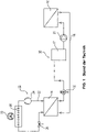
- a coolant circuit 10 is coupled to a refrigerant circuit 12 via a heat exchanger 14 designed as an evaporator.
- the coolant circuit 10 has a coolant line 16 through which the coolant is transported. 18 designates a battery which is cooled by the coolant.
- the coolant itself is drawn off from a reservoir 17 by means of a pump 20 .
- the heat exchanger 14 designed as an evaporator the coolant is cooled down by means of the coolant cooled in the refrigeration circuit 12 .
- the refrigerant circuit has a refrigerant line 22, a compressor 24, a condenser 26 and an expansion valve 28.
- the condenser 26 can be acted upon by a fan 30 with cooling air.
- a bypass valve 32 is provided in the coolant line 16 with which the coolant in the coolant line 16 can be routed completely or partially past the evaporator 14 .
- This cooling circuit circuit has the disadvantage that the mass flow of cooling liquid that flows through the evaporator of the cooling circuit cannot be reduced at will. Depending on the operating point, a minimum cooling capacity must always be introduced into the cooling circuit. As a result, complex partial load control (not shown in detail here) has to be provided in the coolant circuit coupled to the coolant circuit.
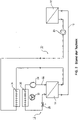
- a vehicle cooling circuit is known, as it is in principle in the figure 2 is shown.
- a coolant circuit 10 is coupled to a coolant circuit 12 via a heat exchanger 14 designed as an evaporator.
- the refrigerant circuit 12 is in turn conventionally constructed and has a refrigerant line 22 , a compressor 24 , a condenser 26 , an expansion valve 28 and a fan 30 .
- the coolant circuit in turn cools a battery 18 , for example, with the coolant flowing through a coolant line 16 and being circulated via a pump 20 .
- a cooler 34 is additionally provided in the coolant circuit, which can be charged with cooling air together with the condenser 26 of the coolant circuit.
- the radiator 34 is disposed upstream of the heat exchanger 14 and downstream of the temperature-raising device (e.g., the battery 18) in the flow direction of the coolant circulated by the pump 20 .
- the cooler cannot be used to emit too much cooling capacity introduced into the cooling circuit by the evaporator in part-load operation back to the environment.
- Another vehicle cooling circuit is in WO 2011/085760 disclosed.
- the object of the invention is to develop a generic vehicle cooling circuit for cooling a temperature-increasing device, in particular a battery, by means of a coolant guided in a coolant circuit in such a way that complicated partial load control in the cooling circuit can be largely dispensed with and the entire system architecture can thus be simplified.
- the individual components are connected to one another in such a way that, when using a refrigeration circuit, they raise the coolant to the desired coolant inlet temperature for the temperature-raising device to be cooled without the need for a part-load solution, which would lead to an adjustment of the cooling capacity provided can be cooled.
- the cooling air flow is generated by a fan.
- the flow of cooling air from the airstream can also be used while the vehicle is moving.
- the cooler can be arranged in the flow of cooling air in front of the condenser.
- cooler is arranged in the cooling air flow after the condenser.
- an additional bypass valve is arranged in the coolant line in such a way that the coolant can be routed completely or partially past the heat exchanger.
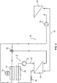
- the coolant circuit 10 according to the invention according to the first exemplary embodiment, as shown in figure 3 is shown is coupled to a refrigerant circuit 12 via a heat exchanger 14 designed as an evaporator.
- the coolant circuit has a coolant line 16, in which the coolant via a pump 20 in the direction of the arrow figure 3 is promoted.
- a temperature-raising device 18, such as a vehicle battery of an electric vehicle, is cooled via the coolant.
- a cooler 34 is also provided, which is cooled by means of a flow of cooling air that is generated by the airstream of the vehicle and/or a fan 30 .
- a further cooling of the coolant circuit takes place via the heat exchanger 14, which is designed as an evaporator of the coolant circuit 12 coupled to the coolant circuit.
- the refrigerant circuit 12 includes, in a known manner, a refrigerant line 22, a compressor 24, a condenser 26 and an expansion valve 28.
- a refrigerant line 22 a refrigerant line 22 a compressor 24, a condenser 26 and an expansion valve 28.
- the aforementioned term “evaporator” is used beyond its actual meaning in the context presented here. For example, if carbon dioxide is used as the coolant, then the "condenser" 26 of the refrigerant circuit 12 acts as a "gas cooler” 26 .
- the cooler 24 is arranged downstream of the heat exchanger 14 as seen in the direction of flow of the coolant in the coolant circuit (cf. the direction of the arrow). Furthermore, a bypass valve 36 is arranged in the coolant line 16 in such a way that the coolant can be routed completely or partially past the cooler 24 .
- the condenser 26 is arranged in front of the cooler 34 in the air flow that is generated, for example, by the fan 30 .
- a greater temperature difference can be generated at the cooler. This increases the possible capacity for "cold removal" at the cooler 34 when the refrigeration circuit 12 is active.
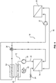
- the embodiment according to figure 4 largely corresponds to that according to figure 3 .
- the condenser 26 is arranged in the air flow after the cooler 24 . This results in a lower capacity for "cold removal" at the cooler when the cooling circuit 12 is active.
- the system architecture shown here opens up the possibility of controlling the condensation temperature in the refrigeration circuit 12.
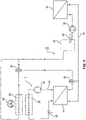
- FIG. 5 a third embodiment of the vehicle cooling circuit according to the invention.
- the structure essentially corresponds to that according to FIG figure 3 .
- an additional bypass valve 38 is also provided, which is arranged in the coolant line 16 in such a way that the coolant can be guided past the heat exchanger 14 in whole or in part.
- This additional bypass 38 opens up a further possibility for partial load control.
- a coolant container 40 can be provided, in which the coolant can be heated to a desired temperature level via an electrical resistance heater 42 .
- Different operating modes can be run with the vehicle cooling circuits according to the invention.
- a first operating mode in which the ambient temperature is higher than the required coolant inlet temperature into the battery 18, the refrigeration circuit 12 is active.
- the compressor 24 is switched on and that in the embodiment according to. figure 5 the evaporator bypass valve 38 opens the path through the heat exchanger 14 designed as an evaporator, with the evaporator bypass being closed.
- the cooler bypass valve 36 opens the cooler bypass and closes the path to the cooler 36.
- the temperature of the coolant can be increased by partially opening the evaporator bypass 38 .
- the maximum permissible degree of opening of the evaporator bypass 38 depends on the operating point of the refrigerant circuit and on the compressor 24 used. If the required coolant inlet temperature is still higher than the provided coolant temperature, the inlet to the cooler 34 can be opened by gradually opening the cooler bypass valve 36, with the bypass line being increasingly closed at the same time. As a result, the temperature of the coolant that is now partially routed via the cooler 34 can be further increased up to the required coolant inlet temperature.
- Coolant inlet temperature can be reduced again to the minimum possible by reversing the above steps, whereby a minimum temperature can be achieved here by the compressor 24 being switched on, that the coolant is passed completely through the evaporator 14 and that the largely cooled Coolant is not passed through the radiator 34.
- the power transmitted to the cooler may be sufficient to lower the coolant temperature below the required coolant inlet temperature.
- the refrigerant circuit 12 does not have to be activated.
- the compressor 24 can remain switched off and the evaporator bypass valve guides the coolant past the heat exchanger 14 designed as an evaporator.
- the cooler bypass valve 36 is switched in such a way that the entire refrigerant flow is routed via the cooler 34 . If the cooling circuit set in this way supplies a lower than the required coolant inlet temperature at the battery 18, the temperature of the coolant can be further increased up to the required coolant inlet temperature by gradually opening the radiator bypass valve 36.
- the refrigerant circuit 12 is activated instead by the compressor 24 being switched on becomes.
- the evaporator bypass valve 38 is switched in such a way that the coolant is routed via the heat exchanger 14 designed as an evaporator. The partial load control then takes place in accordance with the operating mode explained at the outset.
- the condenser 22 is arranged in the air flow after the cooler 34 . In contrast to the circuit according to FIG EP 1 266 779 B1 the possibility of actively cooling the air flow via the condenser 22.
- the required coolant inlet temperature can no longer be reached above a defined outside temperature (e.g. 45°C).
- a defined outside temperature e.g. 45°C
- the refrigerant circuit remains functional up to a maximum outside temperature (of, for example, 55°C).
- the refrigerant circuit does not provide any possibility of power reduction - no matter how configured - the refrigerant circuit must be designed in such a way that it can also be operated at full load at defined maximum temperatures. This means that a larger condenser 26 or an increased air flow through the condenser 26 is necessary.
- the condensation pressure which is a limiting factor for the functionality of the vehicle cooling circuit at high ambient temperatures.
- part of the cooling capacity that is introduced into the cooling circuit at the evaporator 14 is used at the cooler to lower the temperature of the air flow at the condenser inlet and thus also the condensation temperature (corresponds to the condensation pressure) for heat dissipation.
- the cooler bypass valve 36 gradually opens the path through the cooler 34 and closes the bypass line.
- FIG. figure 5 Based on the embodiment gem. figure 5 the integration of a liquid container 40 for holding coolant is shown as an example. This variant can also be used in the exemplary embodiments according to FIG. figure 3 or 4 be provided. Likewise, in the embodiment gem. figure 5 be dispensed with this additional liquid container 40.
- the integration of the electrically operated heater 42 in the liquid container is also provided only as an option.
- This heater can be used, for example, to keep the coolant inlet temperature at a minimum temperature and also increase it if necessary.
- the fan 30 can be set variably in order to vary the amount of air in the cooling air flow.
Landscapes
- Engineering & Computer Science (AREA)
- Chemical & Material Sciences (AREA)
- Power Engineering (AREA)
- Mechanical Engineering (AREA)
- Manufacturing & Machinery (AREA)
- Chemical Kinetics & Catalysis (AREA)
- Electrochemistry (AREA)
- General Chemical & Material Sciences (AREA)
- Transportation (AREA)
- Combustion & Propulsion (AREA)
- General Engineering & Computer Science (AREA)
- Sustainable Energy (AREA)
- Life Sciences & Earth Sciences (AREA)
- Sustainable Development (AREA)
- Thermal Sciences (AREA)
- Physics & Mathematics (AREA)
- Air-Conditioning For Vehicles (AREA)
- Devices That Are Associated With Refrigeration Equipment (AREA)
- Cooling, Air Intake And Gas Exhaust, And Fuel Tank Arrangements In Propulsion Units (AREA)
- Fittings On The Vehicle Exterior For Carrying Loads, And Devices For Holding Or Mounting Articles (AREA)
- Chemical And Physical Treatments For Wood And The Like (AREA)
- Control Of Driving Devices And Active Controlling Of Vehicle (AREA)
Description
- Die Erfindung betrifft einen Fahrzeugkühlkreislauf zur Kühlung einer temperaturerhöhenden Einrichtung in dem Fahrzeug.
- Bei der Entwicklung von neuen Fahrzeuggenerationen besteht das Problem, dass dort temperaturerhöhende Einrichtungen, wie beispielsweise Batterien oder Brennstoffzellen verwendet werden, die während des Betriebs gekühlt werden müssen. Hierbei müssen deutlich höhere Wärmelasten abgeführt werden als dies bei herkömmlichen Fahrzeugen mit Verbrennungsmotoren notwendig war. Da die Abfuhr der Wärmelasten sehr große Wärmeübertrager und sehr hohe Luftvolumenströme an Kühlluft erfordern würden, ist es beispielsweise aus der
US 4,415,847 A bekannt zur Kühlung einer temperaturerhöhenden Einrichtung mittels einem in einem Kühlmittelkreislauf geführten Kühlmittels einen Kühlmittelkreislauf vorzusehen, der mit einem Kältemittelkreislauf kombiniert wird. Der Aufbau des entsprechenden Fahrzeugkühlkreislaufs derUS 4,415,847 A ergibt sich schematisch ausFigur 1 . Hier ist ein Kühlmittelkreislauf 10 mit einem Kältemittelkreislauf 12 über einen als Verdampfer ausgebildeten Wärmetauscher 14 gekoppelt. Der Kühlmittelkreislauf 10 weist eine Kühlmittelleitung 16 auf, durch die das Kühlmittel transportiert wird. Mit 18 ist eine Batterie bezeichnet, die über das Kühlmittel gekühlt wird. Das Kühlmittel selbst wird aus einem Reservoir 17 mittels einer Pumpe 20 abgezogen. In dem als Verdampfer ausgeführten Wärmetauscher 14 wird das Kühlmittel mittels dem im Kältekreislauf 12 gekühlten Kältemittel heruntergekühlt. Der Kältemittelkreislauf weist eine Kältemittelleitung 22, einen Kompressor 24, einen Kondensator 26 und ein Entspannungsventil 28 auf. Der Kondensator 26 kann über einen Ventilator 30 mit Kühlluft beaufschlagt werden. In der Kühlmittelleitung 16 ist ein Bypass Ventil 32 vorgesehen, mit dem das Kühlmittel in der Kühlmittelleitung 16 ganz oder teilweise am Verdampfer 14 vorbeigeführt werden kann. Diese Kühlkreislaufschaltung hat den Nachteil, dass der Massenstrom an Kühlflüssigkeit, der durch den Verdampfer des Kältekreises fließt, nicht beliebig reduziert werden kann. Es muss in Abhängigkeit vom Betriebspunkt immer eine Mindestkälteleistung in den Kühlkreislauf eingebracht werden. Dies führt dazu, dass im mit dem Kühlmittelkreislauf gekoppelten Kältemittelkreislauf eine aufwendige Teillastregelung (hier nicht näher dargestellt) vorgesehen werden muss. - Aus der
EP 1 266 779 B1 ist ein Fahrzeugkühlkreislauf bekannt, wie er im Prinzip in derFigur 2 dargestellt ist. Auch hier ist ein Kühlmittelkreislauf 10 über einen als Verdampfer ausgeführten Wärmetauscher 14 mit einem Kältemittelkreislauf 12 gekoppelt. Der Kältemittelkreislauf 12 ist wiederum konventionell aufgebaut und weist eine Kältemittelleitung 22, einen Kompressor 24, einen Kondensator 26, ein Expansionsventil 28 und einen Lüfter 30 auf. Der Kühlmittelkreislauf wiederum kühlt beispielsweise eine Batterie 18, wobei das Kühlmittel durch eine Kühlmittelleitung 16 fließt und über eine Pumpe 20 umgewälzt wird. Entsprechend derEP 1 266 779 B1 ist im Kühlmittelkreislauf zusätzlich ein Kühler 34 vorgesehen, der gemeinsam mit dem Kondensator 26 des Kältemittelkreislaufs mit Kühlluft beaufschlagbar ist. Der Kühler 34 ist in Strömungsrichtung des mit der Pumpe 20 umgewälzten Kühlmittels gesehen stromaufwärts des Wärmetauschers 14 und stromabwärts zur temperaturerhöhenden Einrichtung (beispielsweise der Batterie 18) angeordnet. Hierdurch bedingt kann der Kühler nicht dazu benutzt werden, eventuell zuviel durch den Verdampfer in den Kühlkreislauf eingebrachte Kälteleistung im Teillastbetrieb wieder an die Umgebung abzugeben. Ein weiterer Fahrzeugkühlkreislauf ist inWO 2011/085760 offenbart. - Die Aufgabe der Erfindung besteht darin, einen gattungsgemäßen Fahrzeugkühlkreislauf zur Kühlung einer temperaturerhöhenden Einrichtung, insbesondere einer Batterie, mittels einem in einem Kühlmittelkreislauf geführten Kühlmittel derart weiterzubilden, dass auf eine komplizierte Teillastregelung im Kältekreislauf weitgehend verzichtet werden kann und so die gesamte Systemarchitektur vereinfacht werden kann.
- Erfindungsgemäß wird diese Aufgabe durch die Kombination der Merkmale des Anspruchs 1 gelöst.
- Durch die erfindungsgemäße Anordnung des Fahrzeugkühlkreislaufs werden die einzelnen Komponenten derart miteinander verschaltet, dass diese bei Verwendung eines Kältekreises ohne die Notwendigkeit zu einer Teillastlösung, die zur Anpassung der zur Verfügung gestellten Kälteleistung führen würde, das Kühlmittel auf die gewünschte Kühlmitteleintrittstemperatur für die zu kühlende temperaturerhöhende Einrichtung gekühlt werden kann. Im Idealfall können sogar die zusätzlich notwendigen Komponenten für die Teillastregelung eines Kältekreises eingespart werden, wodurch die Systemarchitektur des gesamten Fahrzeugkühlkreislaufs wesentlich vereinfacht wird.
- Aus den sich an den Hauptanspruch anschließenden Unteransprüchen ergeben sich bevorzugte Ausführungsformen der Erfindung.
- Der Kühlluftstrom wird durch einen Ventilator erzeugt. Selbstverständlich kann zusätzlich der Kühlluftstrom des Fahrtwindes während der Fortbewegung des Fahrzeuges genutzt werden.
- Gemäß einer besonderen Ausgestaltung der Erfindung kann der Kühler im Kühlluftstrom vor dem Kondensator angeordnet sein.
- Eine andere bevorzugte Ausgestaltung der Erfindung kann auch darin gegeben sein, dass der Kühler im Kühlluftstrom nach dem Kondensator angeordnet ist. Schließlich kann es vorteilhaft sein, wenn in der Kühlmittelleitung ein zusätzliches Bypass Ventil derart angeordnet ist, dass das Kühlmittel ganz oder teilweise an dem Wärmetauscher vorbeiführbar ist.
- Weitere Merkmale, Einzelheiten und Vorteile der Erfindung ergeben sich aus den in der Zeichnung dargestellten Ausführungsbeispielen. Es zeigen:
- Figur 1:
- ein Fahrzeugkühlreislauf nach einem Stand der Technik wie er aus der
US 4,415,847 A bekannt ist, - Figur 2:
- einen Fahrzeugkühlkreislauf wie er aus einem Stand der Technik gemäß der
EP 1 266 779 B1 bekannt ist, - Figur 3:
- eine erste Ausführungsform eines Fahrzeugkühlkreislaufs nach der vorliegenden Erfindung,
- Figur 4:
- eine zweite Ausführungsform eines erfindungsgemäßem Fahrzeugkühlkreislaufs nach der vorliegenden Erfindung und
- Figur 5:
- eine dritte Ausführungsform eines Fahrzeugkühlkreislaufs nach der vorliegenden Erfindung.
- Der erfindungsgemäße Kühlmittelkreislauf 10 nach dem ersten Ausführungsbeispiel, wie es in
Figur 3 dargestellt ist, ist über einen als Verdampfer ausgebildeten Wärmetauscher 14 mit einem Kältemittelkreislauf 12 gekoppelt. Der Kühlmittelkreislauf weist eine Kühlmittelleitung 16 auf, in welcher das Kühlmittel über eine Pumpe 20 in Pfeilrichtung gemäßFigur 3 gefördert wird. Über das Kühlmittel wird eine temperaturerhöhende Einrichtung 18, wie beispielsweise eine Fahrzeugbatterie eines Elektrofahrzeugs, gekühlt. Ferner ist ein Kühler 34 vorgesehen, der mittels eines Kühlluftstroms, der über den Fahrtwind des Fahrzeugs und/oder einen Ventilator 30 erzeugt wird, gekühlt wird. Eine weitere Kühlung des Kühlmittelkreislaufs erfolgt über den Wärmetauscher 14, der als Verdampfer des mit dem Kühlmittelkreislauf gekoppelten Kältemittelkreislaufs 12 ausgebildet ist. Der Kältemittelkreislauf 12 umfasst neben diesem Verdampfer 14 in bekannter Weise eine Kältemittelleitung 22, einen Kompressor 24, einen Kondensator 26 und ein Expansionsventil 28. Der vorgenannte Begriff "Verdampfer" ist im hier dargestellten Zusammenhang über seine eigentliche Wortbedeutung hinaus verwendet. Wird beispielsweise Kohlendioxid als Kühlmittel eingesetzt, dann ist der "Kondensator" 26 des Kältemittelkreislaufs12 als "Gaskühler" 26 wirksam. - Wie aus der
Figur 3 ersichtlich, ist der Kühler 24 in Strömungsrichtung des Kühlmittels im Kühlmittelkreislauf gesehen (vgl. die Pfeilrichtung) stromabwärts des Wärmetauschers 14 angeordnet. Des weiteren ist in der Kühlmittelleitung 16 ein Bypass Ventil 36 derart angeordnet, dass das Kühlmittel ganz oder teilweise an dem Kühler 24 vorbeiführbar ist. - In der Ausführungsform gemäß
Figur 3 ist der Verflüssiger 26 im Luftstrom, der beispielsweise durch den Ventilator 30 erzeugt wird, vor dem Kühler 34 angeordnet. Hierdurch ist eine größere Temperaturdifferenz am Kühler erzeugbar. Dies erhöht die mögliche Kapazität zur "Kälteabfuhr" am Kühler 34 bei aktivem Kältekreis 12. - Die Ausführungsform gemäß
Figur 4 entspricht weitestgehend derjenigen gemäßFigur 3 . Hier ist lediglich der Verflüssiger 26 im Luftstrom nach dem Kühler 24 angeordnet. Hierdurch ergibt sich eine geringere Kapazität an "Kälteabfuhr" am Kühler bei aktivem Kältekreislauf 12. Zum anderen besteht die Möglichkeit bei sehr hohen Umgebungstemperaturen durch aktives Kühlen des Luftstroms durch den Verflüssiger 26 mit dem Kühler 34 die Kondensationstemperatur zu senken und so die Funktionsfähigkeit des Fahrzeugkühlkreislaufs bei hohen Umgebungstemperaturen vergleichsweise länger zu gewährleisten. Die hier dargestellte Systemarchitektur eröffnet die Möglichkeit zur Regelung der Kondensationstemperatur im Kältekreislauf 12. - Schließlich ergibt sich aus der
Figur 5 ein drittes Ausführungsbeispiel des erfindungsgemäßen Fahrzeugkühlkreislaufs. Der Aufbau entspricht im Wesentlichen demjenigen gemäßFigur 3 . Allerdings ist noch ein zusätzliches Bypass Ventil 38 vorgesehen, das derart in der Kühlmittelleitung 16 angeordnet ist, dass das Kühlmittel ganz oder teilweise an dem Wärmetauscher 14 vorbeiführbar ist. Durch diesen zusätzlichen Bypass 38, mit dem der als Verdampfer ausgeführte Wärmetauscher 14 umgangen werden kann, wird eine weitere Möglichkeit zur Teillastregelung eröffnet. - Zusätzlich kann ein Kühlmittelbehälter 40 vorgesehen sein, in dem das Kühlmittel über eine elektrische Widerstandsheizung 42 auf ein gewünschtes Temperaturniveau temperiert werden kann.
- Mit den erfindungsgemäßen Fahrzeugkühlkreisläufen können unterschiedliche Betriebsmodi gefahren werden. Gemäß einem ersten Betriebsmodus, bei dem die Umgebungstemperatur höher als die geforderte Kühlmitteleintrittstemperatur in die Batterie 18 ist, ist der Kältekreislauf 12 aktiv. Das bedeutet, dass der Verdichter 24 eingeschaltet ist und dass in der Ausführungsvariante gemäß.
Figur 5 das Verdampfer Bypass Ventil 38 den Weg durch den als Verdampfer ausgeführten Wärmetauscher 14 freigibt, wobei der Verdampfer Bypass geschlossen ist. Das Kühler Bypass Ventil 36 öffnet den Kühler Bypass und schließt den Weg zum Kühler 36. - Soweit der Kältemittelkreislauf 12 am Austritt aus dem Verdampfer 14 eine niedrigere als die geforderte Kühlmitteleintrittstemperatur aufweist, kann durch teilweises Öffnen des Verdampfer Bypasses 38 die Temperatur des Kühlmittels erhöht werden. Der maximal zulässige Öffnungsgrad des Verdampfer Bypasses 38 ist vom Betriebspunkt des Kältemittelkreislaufs und vom verwendeten Verdichter 24 abhängig. Ist die geforderte Kühlmitteleintrittstemperatur immer noch höher als die bereitgestellte Kühlmitteltemperatur, kann durch schrittweises Öffnen des Kühler Bypass Ventils 36 der Zulauf zum Kühler 34 geöffnet werden, wobei gleichzeitig die Bypass Leitung zunehmend geschlossen wird. Hierdurch kann die Temperatur des nunmehr teilweise über den Kühler 34 geführten Kühlmittels weiter bis zur geforderten Kühlmitteleintrittstemperatur erhöht werden.
- Liefert der Kühlkreislauf eine höhere als die geforderte Kühlmitteleintrittstemperatur kann durch Umkehrung der zuvor genannten Schritte die Kühlmitteltemperatur wieder bis zur minimal möglichen gesenkt werden, wobei hier eine minimale Temperatur dadurch erreicht werden kann, dass der Verdichter 24 eingeschaltet ist, dass das Kühlmittel vollständig über den Verdampfer 14 geführt wird und dass das weitgehend abgekühlte Kühlmittel nicht über den Kühler 34 geführt wird.
- Für den Fall, dass die Umgebungstemperatur kleiner als die geforderte Kühlmitteleintrittstemperatur in die Batterie ist, reicht unter Umständen die übertragene Leistung am Kühler aus, um die Temperatur des Kühlmittels unter die geforderte Kühlmitteleintrittstemperatur zu senken. In diesem Fall muss der Kältemittelkreislauf 12 nicht aktiviert werden. Der Verdichter 24 kann ausgeschalten bleiben und das Verdampfer Bypass Ventil führt das Kühlmittel an den als Verdampfer ausgeführten Wärmetauscher 14 vorbei. Das Kühler Bypass Ventil 36 ist derart geschaltet, dass der gesamte Kältemittelstrom über den Kühler 34 geführt wird. Liefert der so eingestellte Kühlkreislauf eine niedrigere als die geforderte Kühlmitteleintrittstemperatur an der Batterie 18, kann durch schrittweises Öffnen des Kühler Bypass Ventils 36 die Temperatur des Kühlmittels weiter bis zur geforderten Kühlmitteleintrittstemperatur erhöht werden.
- Ist die Umgebungstemperatur zwar geringer als die geforderte Kühlmitteleintrittstemperatur in die Batterie, reicht aber die übertragene Kühlleistung am Kühler 34 nicht aus, um das Kühlmittel auf die geforderte Kühlmitteleintrittstemperatur am Eingang der Batterie zu kühlen, wird stattdessen der Kältemittelkreislauf 12 aktiviert, indem der Verdichter 24 angestellt wird. Das Verdampfer Bypass Ventil 38 wird gleichzeitig so geschaltet, dass das Kühlmittel über den als Verdampfer ausgelegten Wärmetauscher 14 geführt wird. Die Teillastregelung erfolgt dann entsprechend des eingangs erläuterten Betriebsmodus.
- Mit der in
Figur 4 dargestellten Ausführungsvariante des Fahrzeugkühlkreislaufs kann in einem weiteren Betriebsmodus die Funktionsfähigkeit bei sehr hohen Außentemperaturen sichergestellt werden. Bei dieser Ausführungsvariante ist der Kondensator 22 im Luftstrom nach dem Kühler 34 angeordnet. Hier ergibt sich im Unterschied zu der Schaltung gemäß derEP 1 266 779 B1 die Möglichkeit, den Luftstrom über den Kondensator 22 aktiv zu kühlen. - Zur Erläuterung ist diesbezüglich anzugeben, dass ab einer definierten Außentemperatur (beispielsweise 45°C) die geforderte Kühlmitteleintrittstemperatur nicht mehr erreicht werden kann. Andererseits besteht die Forderung, dass der Kältemittelkreislauf bis zu einer maximalen Außentemperatur (von beispielsweise 55°C) funktionsfähig bleibt.
- Ist im Kältemittelkreislauf keine - wie auch immer ausgestaltete - Möglichkeit zur Leistungsreduktion vorgesehen, muss der Kältemittelkreislauf so ausgeführt sein, dass dieser auch bei Volllastbetrieb bei definierten Maximaltemperaturen betrieben werden kann. Das bedeutet, dass ein größerer Kondensator 26 bzw. ein erhöhter Luftstrom durch den Kondensator 26 notwendig ist.
- Bei der Systemarchitektur nach der
Figur 4 ist es allerdings möglich, den Kondensationsdruck zu senken, der eine limitierende Größe für die Funktionsfähigkeit des Fahrzeugkühlkreislaufs bei hohen Umgebungstemperaturen ist. Hierzu wird ein Teil der Kälteleistung, die am Verdampfer 14 in den Kühlkreislauf eingebracht wird, am Kühler dazu verwendet, die Temperatur des Luftstroms am Kondensatoreintritt zu senken und somit auch die Kondensationstemperatur (entspricht dem Kondensationsdruck) zur Wärmeabfuhr. Das Kühler Bypass Ventil 36 öffnet schrittweise den Weg durch den Kühler 34 und schließt die Bypass Leitung. - Anhand der Ausführungsform gem.
Figur 5 ist die Integration eines Flüssigkeitsbehälters 40 zur Aufnahme von Kühlmittel beispielhaft dargestellt. Diese Ausführungsvariante kann auch in den Ausführungsbeispielen gem.Figur 3 oder4 vorgesehen sein. Desgleichen kann in der Ausführungsform gem.Figur 5 auf diesen zusätzlichen Flüssigkeitsbehälter 40 verzichtet werden. - Die Integration der elektrisch betriebenen Heizung 42 im Flüssigkeitsbehälter ist ebenfalls nur wahlweise vorgesehen. Über diese Heizung kann beispielsweise die Kühlmitteleintrittstemperatur auf einer Minimaltemperatur gehalten werden und bei Bedarf auch erhöht werden.
- Gemäß einer weiteren Ausführungsform kann der Lüfter 30 variabel eingestellt werden, um hier die Luftmenge des Kühlluftstroms zu variieren.
Claims (8)
- Fahrzeugkühlkreislauf zur Kühlung einer temperaturerhöhenden Einrichtung (18), insbesondere einer Batterie (18), mittels einem in einem Kühlmittelkreislauf (12) geführten Kühlmittel, wobei der Kühlmittelkreislauf (12) eine Kühlmittelleitung (16), mindestens einen Kühler (34), eine Kühlmittelpumpe (20) und mindestens einen als Verdampfer ausgelegten Wärmetauscher (14) aufweist, über den der Kühlmittelkreislauf (12) mit einem Kältemittelkreislauf gekoppelt ist, der zusätzlich eine Kältemittelleitung (22), mindestens einen Kompressor (24), mindestens einen Kondensator (26) und mindestens ein Expansionsventil aufweist,
dadurch gekennzeichnet,
dass der mindestens eine Kühler (34) in Strömungsrichtung des Kühlmittels im Kühlmittelkreislauf (12) stromabwärts des mindestens einen Wärmetauschers (14) und stromaufwärts der temperaturerhöhenden Einrichtung (18) angeordnet ist und dass in der Kühlmittelleitung (16) mindestens ein ganz oder teilweise öffenbares Bypass Ventil (36) derart angeordnet ist, dass das Kühlmittel ganz oder teilweise an dem mindestens einen Kühler (34) vorbeiführbar ist, wobei sowohl der Kühler (34) als auch der Kondensator (26) einem Kühlluftstrom, der durch einen Ventilator (30) erzeugbar ist, zugeordnet sind. - Fahrzeugkühlkreislauf nach Anspruch 1, dadurch gekennzeichnet, dass der Kühler (34) im Kühlluftstrom vor dem Kondensator (26) angeordnet ist.
- Fahrzeugkühlkreislauf nach Anspruch 1, dadurch gekennzeichnet, dass der Kühler (34) im Kühlluftstrom nach dem Kondensator (26) angeordnet ist.
- Fahrzeugkühlkreislauf nach einem der vorangehenden Ansprüche, dadurch gekennzeichnet, dass in der Kühlmittelleitung (16) ein zusätzliches Bypass Ventil (38) derart angeordnet ist, dass das Kühlmittel ganz oder teilweise an dem Wärmetauscher (14) vorbeiführbar ist.
- Fahrzeugkühlkreislauf nach einem der vorangehenden Ansprüche, dadurch gekennzeichnet, dass in der Kühlmittelleitung (16) ein Flüssigkeitsbehälter (40) zur Aufnahme von Kühlmittel integriert ist.
- Fahrzeugkühlkreislauf nach Anspruch 5, dadurch gekennzeichnet, dass im Kühlmittelkreis, insbesondere im Flüssigkeitsbehälter (40), eine Heizung (42) integriert ist.
- Fahrzeugkühlkreislauf nach Anspruch 1, dadurch gekennzeichnet, dass der Ventilator (30) eine einstellbare Drehzahl zur Einstellung des Kühlluftvolumenstroms aufweist.
- Fahrzeug, insbesondere Schienenfahrzeug, mit einem Fahrzeugkreislauf nach einem der vorangegangenen Ansprüche.
Applications Claiming Priority (1)
| Application Number | Priority Date | Filing Date | Title |
|---|---|---|---|
| DE102014001022.8A DE102014001022A1 (de) | 2014-01-27 | 2014-01-27 | Fahrzeugkühlkreislauf |
Publications (3)
| Publication Number | Publication Date |
|---|---|
| EP2903076A1 EP2903076A1 (de) | 2015-08-05 |
| EP2903076B1 EP2903076B1 (de) | 2018-12-19 |
| EP2903076B2 true EP2903076B2 (de) | 2022-08-10 |
Family
ID=52358549
Family Applications (1)
| Application Number | Title | Priority Date | Filing Date |
|---|---|---|---|
| EP14199756.9A Active EP2903076B2 (de) | 2014-01-27 | 2014-12-22 | Fahrzeugkühlkreislauf |
Country Status (6)
| Country | Link |
|---|---|
| US (1) | US9810137B2 (de) |
| EP (1) | EP2903076B2 (de) |
| CN (1) | CN104842752B (de) |
| CA (1) | CA2877549C (de) |
| DE (1) | DE102014001022A1 (de) |
| ES (1) | ES2716376T5 (de) |
Families Citing this family (42)
| Publication number | Priority date | Publication date | Assignee | Title |
|---|---|---|---|---|
| US9873350B2 (en) * | 2015-09-16 | 2018-01-23 | Ford Global Technologies, Llc | Hybrid vehicle and method of conditioning a vehicle battery |
| US11052776B2 (en) * | 2015-09-24 | 2021-07-06 | Ford Global Technologies, Llc | Charging station for electrified vehicles |
| CN105501071B (zh) * | 2015-12-23 | 2018-05-11 | 奇瑞汽车股份有限公司 | 汽车热管理系统 |
| CN105742754A (zh) * | 2016-04-03 | 2016-07-06 | 北京工业大学 | 一种电池包液体冷却/加热系统试验装置 |
| US10153523B2 (en) * | 2016-04-27 | 2018-12-11 | Ford Global Technologies, Llc | Traction battery thermal management method and system |
| US10220722B2 (en) * | 2016-08-22 | 2019-03-05 | Ford Global Technologies, Llc | Operation of combined cooling circuit for power electronics and battery |
| EP3419843B1 (de) * | 2016-09-02 | 2022-11-16 | Apple Inc. | Fahrzeugwärmeverwaltungssystem und wärmetauscher |
| CN107953785A (zh) * | 2016-10-18 | 2018-04-24 | 南京金邦动力科技有限公司 | 一种充电汽车电池的散热装置及其散热方法 |
| CN107360700B (zh) * | 2017-07-21 | 2019-11-15 | 新乡市特美特换热设备有限公司 | 一种大功率电子设备变频制冷系统及相变蓄能装置的控制方法 |
| DE102017215984B4 (de) * | 2017-09-11 | 2023-11-09 | Vitesco Technologies GmbH | Steuermodul zur Klimatisierung einer Batterie |
| FR3071048B1 (fr) * | 2017-09-11 | 2019-08-23 | Valeo Systemes Thermiques | Procede de demarrage d'un circuit de fluide refrigerant comprenant une pompe liquide |
| CN107946694B (zh) * | 2017-12-22 | 2019-09-03 | 吉林大学 | 一种动力电池冷却系统及其冷却方法 |
| WO2019126996A1 (zh) * | 2017-12-26 | 2019-07-04 | 曙光节能技术(北京)股份有限公司 | 一种浸没式的动力电池散热装置 |
| US11342603B2 (en) * | 2018-01-15 | 2022-05-24 | Ford Global Technologies, Llc | Thermal management of traction battery based on electric current of traction battery |
| WO2019155179A1 (fr) * | 2018-02-12 | 2019-08-15 | Valeo Systemes Thermiques | Systeme de refroidissement d'au moins une batterie de véhicule automobile |
| DE102018209769B4 (de) | 2018-06-18 | 2022-05-19 | Audi Ag | Verfahren zum Betreiben einer einen Kältemittelkreislauf aufweisenden Kälteanlage eines Fahrzeugs |
| JP7033730B2 (ja) * | 2018-07-11 | 2022-03-11 | パナソニックIpマネジメント株式会社 | 冷却装置、電池温度調整システム及び車両 |
| CN108870789A (zh) * | 2018-07-12 | 2018-11-23 | 珠海格力电器股份有限公司 | 冷却机组 |
| JP2020075623A (ja) * | 2018-11-08 | 2020-05-21 | 株式会社デンソー | 車両用空調装置 |
| KR20200057857A (ko) * | 2018-11-16 | 2020-05-27 | 현대자동차주식회사 | 차량용 냉각 장치 |
| KR102704104B1 (ko) * | 2018-12-06 | 2024-09-06 | 현대자동차주식회사 | 친환경 차량의 냉각 시스템 |
| JP7192533B2 (ja) * | 2019-01-29 | 2022-12-20 | トヨタ自動車株式会社 | バッテリ冷却制御装置 |
| US11721857B2 (en) | 2019-03-20 | 2023-08-08 | Hamilton Sundstrand Corporation | Thermal regulation of batteries |
| US11749851B2 (en) | 2019-03-20 | 2023-09-05 | Hamilton Sundstrand Corporation | Thermal regulation of batteries |
| EP3753851A3 (de) * | 2019-06-21 | 2021-03-03 | Hamilton Sundstrand Corporation | Wärmeregelung von batterien |
| DE102019216051A1 (de) * | 2019-10-17 | 2021-04-22 | Kautex Textron Gmbh & Co. Kg | Kondensierungsvorrichtung, Kühlvorrichtung für eine Traktionsbatterie, elektrisch antreibbares Fahrzeug mit einer Traktionsbatterie sowie einer Kühlvorrichtung und Verfahren zur Kühlung einer Traktionsbatterie |
| CN111267578B (zh) * | 2020-04-01 | 2024-11-05 | 上海加冷松芝汽车空调股份有限公司 | 一种电池热管理系统 |
| CN113580871B (zh) * | 2020-04-30 | 2023-10-17 | 比亚迪股份有限公司 | 车辆及其热管理系统 |
| JP7531327B2 (ja) * | 2020-06-26 | 2024-08-09 | 本田技研工業株式会社 | 車両用空調装置 |
| CN111806196B (zh) * | 2020-07-11 | 2024-05-07 | 的卢技术有限公司 | 一种汽车热泵系统及控制方法 |
| CN112050536B (zh) * | 2020-09-15 | 2021-09-21 | 安徽江淮汽车集团股份有限公司 | 一种恒温冷却水循环供给系统及循环供给方法 |
| DE102021131215B4 (de) * | 2020-12-17 | 2025-11-27 | Hanon Systems | Wärmepumpenanordnung mit einem Chiller für batteriebetriebene Fahrzeuge und Verfahren zum Betreiben der Wärmepumpenanordnung |
| CN112622567B (zh) * | 2020-12-25 | 2022-05-20 | 青岛朗进新能源设备有限公司 | 一种集成电池冷却功能的车载空调系统 |
| US11731532B2 (en) * | 2021-01-06 | 2023-08-22 | GM Global Technology Operations LLC | Selective thermal mechanization for RESS heat loads |
| CN112902471B (zh) * | 2021-02-04 | 2022-11-01 | 浙江吉利控股集团有限公司 | 一种车辆冷却的控制方法、控制系统和车辆 |
| CN113540619A (zh) * | 2021-08-11 | 2021-10-22 | 西安西热锅炉环保工程有限公司 | 一种火电厂储能系统的水冷系统及工作方法 |
| EP4163530A1 (de) * | 2021-10-08 | 2023-04-12 | Hanil Tube Corporation | Kupplungsanordnung mit ventilen |
| CN115071400A (zh) * | 2022-06-28 | 2022-09-20 | 上海集度汽车有限公司 | 车辆热管理系统及车辆 |
| CN115091934B (zh) * | 2022-07-04 | 2025-04-08 | 岚图汽车科技有限公司 | 一种电池包、热管理系统及车辆 |
| KR20240030544A (ko) * | 2022-08-31 | 2024-03-07 | 현대자동차주식회사 | 배터리 온도관리와 공조를 통합한 차량의 제어시스템 |
| CN116255749B (zh) * | 2023-05-12 | 2023-08-01 | 广东美的暖通设备有限公司 | 温控机组、温度控制方法、温度控制装置及控制器 |
| CN117352885A (zh) * | 2023-11-09 | 2024-01-05 | 暨南大学 | 一种动力电池热流泄放装置及动力电池热流泄放方法 |
Citations (9)
| Publication number | Priority date | Publication date | Assignee | Title |
|---|---|---|---|---|
| DE3130390A1 (de) † | 1981-07-31 | 1983-02-10 | Siemens AG, 1000 Berlin und 8000 München | Kaelteaggregat |
| US4415847A (en) † | 1981-08-07 | 1983-11-15 | Energy Development Associates, Inc. | Method and apparatus for supplying cooling liquid to a storage battery |
| EP1266779A2 (de) † | 2001-06-15 | 2002-12-18 | Behr GmbH & Co. | Fahrzeug-Kühlkreislauf für die Kühlung einer temperaturerhöhenden Einrichtung mittels eines Kuhlmittels |
| US20050022983A1 (en) † | 2003-07-15 | 2005-02-03 | Kadle Prasad Shripad | Heat pump with secondary loop air-conditioning system |
| EP2273894A1 (de) † | 2008-04-04 | 2011-01-19 | Firmenich S.A. | Geschmacksmodifizierendes produkt |
| DE102009056083A1 (de) † | 2009-11-30 | 2011-06-09 | Wilhelm Karmann Gmbh | Temperierungssystem eines Kraftfahrzeuges mit einem Elektromotor |
| WO2011079904A1 (de) † | 2009-12-30 | 2011-07-07 | Voss Automotive Gmbh | Klimatisierungssystem für ein fahrzeug sowie verfahren zum temperieren |
| US20120085512A1 (en) † | 2010-10-07 | 2012-04-12 | Audi Ag | Vehicle cooling system |
| WO2012172751A1 (ja) † | 2011-06-13 | 2012-12-20 | 株式会社デンソー | 車両用温度調節装置 |
Family Cites Families (20)
| Publication number | Priority date | Publication date | Assignee | Title |
|---|---|---|---|---|
| US2779171A (en) * | 1954-01-04 | 1957-01-29 | Rca Corp | Room temperature conditioner |
| JPS6093116A (ja) * | 1983-10-26 | 1985-05-24 | Nissan Motor Co Ltd | 蒸発冷却式インタ−ク−ラ装置 |
| US5040377A (en) * | 1989-11-21 | 1991-08-20 | Johnson Service Company | Cooling system with improved fan control and method |
| JPH0735392Y2 (ja) * | 1989-11-30 | 1995-08-09 | 日鉄セミコンダクター株式会社 | 半導体の製造設備 |
| DE59104534D1 (de) * | 1990-07-20 | 1995-03-23 | Siemens Nixdorf Inf Syst | Kaltwassersatz mit Leistungsanpassung. |
| DE4209188C2 (de) * | 1992-03-20 | 1994-02-03 | Kulmbacher Klimageraete | Anordnung zur Klimatisierung von Räumen, insbesondere der Fahrgastzelle von Kraftfahrzeugen |
| EP0842798B1 (de) * | 1996-11-15 | 2005-10-05 | Calsonic Kansei Corporation | Fahrzeugklimaanlage |
| TW522214B (en) * | 1999-12-08 | 2003-03-01 | Usui International Industry | Temperature adjusting device for thermal fluid medium |
| JP3079839U (ja) | 2001-02-26 | 2001-08-31 | 伸和コントロールズ株式会社 | チラー用温調装置 |
| JP4055892B2 (ja) * | 2002-05-31 | 2008-03-05 | 東京エレクトロン株式会社 | 冷媒の温度制御方法、冷却方法及び冷却装置 |
| DE102004041252A1 (de) * | 2004-08-26 | 2006-03-02 | Thermo Electron (Karlsruhe) Gmbh | Temperiervorrichtung |
| JP2006194518A (ja) * | 2005-01-13 | 2006-07-27 | Daikin Ind Ltd | 冷凍装置 |
| FR2884058B1 (fr) * | 2005-04-05 | 2016-07-15 | Valeo Systemes Thermiques Branche Thermique Habitacle | Dispositif de maintien a une temperature de consigne d'une batterie d'un vehicule a motorisation electrique par fluide caloporteur |
| US8118257B2 (en) * | 2006-04-28 | 2012-02-21 | Hamilton Sundstrand Corporation | Thermal management system with staged cooling |
| US20100009246A1 (en) * | 2008-07-09 | 2010-01-14 | Bayerische Motoren Werke Aktiengesellschaft | Bypass Function for a High Voltage Battery Cooling Strategy |
| DE102009054186A1 (de) * | 2009-11-23 | 2011-05-26 | Behr Gmbh & Co. Kg | System für ein Kraftfahrzeug zum Erwärmen und/oder Kühlen einer Batterie und eines Kraftfahrzeuginnenraumes |
| DE102009059982A1 (de) * | 2009-12-22 | 2011-06-30 | Volkswagen AG, 38440 | Verfahren zum Temperieren einer Stromquelle eines Fahrzeugs |
| JP5452409B2 (ja) * | 2010-07-30 | 2014-03-26 | 株式会社日立製作所 | 熱サイクルシステム |
| US9127587B2 (en) * | 2010-11-30 | 2015-09-08 | General Electric Company | Cooling system for an engine and method of providing a cooling system for an engine |
| US20120291459A1 (en) * | 2011-05-17 | 2012-11-22 | The Boeing Company | Method and apparatus for aircraft galley cooling |
-
2014
- 2014-01-27 DE DE102014001022.8A patent/DE102014001022A1/de active Pending
- 2014-12-22 ES ES14199756T patent/ES2716376T5/es active Active
- 2014-12-22 EP EP14199756.9A patent/EP2903076B2/de active Active
-
2015
- 2015-01-13 CA CA2877549A patent/CA2877549C/en active Active
- 2015-01-27 CN CN201510057180.1A patent/CN104842752B/zh active Active
- 2015-01-27 US US14/606,917 patent/US9810137B2/en active Active
Patent Citations (9)
| Publication number | Priority date | Publication date | Assignee | Title |
|---|---|---|---|---|
| DE3130390A1 (de) † | 1981-07-31 | 1983-02-10 | Siemens AG, 1000 Berlin und 8000 München | Kaelteaggregat |
| US4415847A (en) † | 1981-08-07 | 1983-11-15 | Energy Development Associates, Inc. | Method and apparatus for supplying cooling liquid to a storage battery |
| EP1266779A2 (de) † | 2001-06-15 | 2002-12-18 | Behr GmbH & Co. | Fahrzeug-Kühlkreislauf für die Kühlung einer temperaturerhöhenden Einrichtung mittels eines Kuhlmittels |
| US20050022983A1 (en) † | 2003-07-15 | 2005-02-03 | Kadle Prasad Shripad | Heat pump with secondary loop air-conditioning system |
| EP2273894A1 (de) † | 2008-04-04 | 2011-01-19 | Firmenich S.A. | Geschmacksmodifizierendes produkt |
| DE102009056083A1 (de) † | 2009-11-30 | 2011-06-09 | Wilhelm Karmann Gmbh | Temperierungssystem eines Kraftfahrzeuges mit einem Elektromotor |
| WO2011079904A1 (de) † | 2009-12-30 | 2011-07-07 | Voss Automotive Gmbh | Klimatisierungssystem für ein fahrzeug sowie verfahren zum temperieren |
| US20120085512A1 (en) † | 2010-10-07 | 2012-04-12 | Audi Ag | Vehicle cooling system |
| WO2012172751A1 (ja) † | 2011-06-13 | 2012-12-20 | 株式会社デンソー | 車両用温度調節装置 |
Also Published As
| Publication number | Publication date |
|---|---|
| EP2903076B1 (de) | 2018-12-19 |
| US9810137B2 (en) | 2017-11-07 |
| CA2877549A1 (en) | 2015-07-27 |
| ES2716376T3 (es) | 2019-06-12 |
| ES2716376T5 (es) | 2022-11-29 |
| DE102014001022A1 (de) | 2015-07-30 |
| CA2877549C (en) | 2021-10-05 |
| CN104842752A (zh) | 2015-08-19 |
| US20150211412A1 (en) | 2015-07-30 |
| EP2903076A1 (de) | 2015-08-05 |
| CN104842752B (zh) | 2018-10-23 |
Similar Documents
| Publication | Publication Date | Title |
|---|---|---|
| EP2903076B2 (de) | Fahrzeugkühlkreislauf | |
| DE102021131215B4 (de) | Wärmepumpenanordnung mit einem Chiller für batteriebetriebene Fahrzeuge und Verfahren zum Betreiben der Wärmepumpenanordnung | |
| EP3454401B1 (de) | Kraftfahrzeug mit einem kühlsystem | |
| EP2072296B1 (de) | Vorrichtung zur Kühlung einer Wärmequelle eines Kraftfahrzeugs | |
| DE102017218424B4 (de) | Verfahren zum Betreiben eines Kältemittelkreislaufs sowie Fahrzeugkälteanlage | |
| DE102020117471B4 (de) | Wärmepumpenanordnung mit indirekter Batterieerwärmung für batteriebetriebene Kraftfahrzeuge und Verfahren zum Betreiben einer Wärmepumpenanordnung | |
| DE102015220623B4 (de) | Wärmesystem für ein Elektro- oder Hybridfahrzeug | |
| DE102020107111B4 (de) | Wärmepumpenanordnung für Fahrzeuge mit einem Fahrzeugkabinenheizkreislauf und einem Batterieheizkreislauf | |
| EP3711983A1 (de) | Wärmesystem für ein elektro- oder hybridfahrzeug, elektro- oder hybridfahrzeug, verfahren zum betrieb eines wärmesystems | |
| EP1961593A1 (de) | Klimaanlage für ein Fahrzeug | |
| WO2019096696A1 (de) | Kühlsystem für ein kraftfahrzeug und kraftfahrzeug mit einem solchen kühlsystem | |
| DE102013206630A1 (de) | Kühl- und Heizsystem für ein Elektro- oder Hybrid-Fahrzeug sowie Verfahren zum Betreiben eines derartigen Kühl- und Heizsystems | |
| EP2471136A1 (de) | Fahrzeug mit wenigstens einem kühlkreislauf zum kühlen eines brennstoffzellensystems | |
| DE102015003028A1 (de) | Kühlanordnung zum Kühlen einer Brennstoffzelle | |
| EP2287952B1 (de) | Temperiervorrichtung | |
| DE102017204116B4 (de) | Kälteanlage eines Fahrzeugs mit einem als Kältekreislauf für einen Kältebetrieb und als Wärmepumpenkreislauf für einen Heizbetrieb betreibbaren Kältemittelkreislauf | |
| DE102021127770A1 (de) | Thermomanagementsystem für ein Kraftfahrzeug und Kraftfahrzeug mit einem solchen | |
| DE102011085961A1 (de) | Kühlkreislauf | |
| DE102021206598A1 (de) | Vorrichtung zum Abführen von Bremsenergie | |
| WO2023061685A1 (de) | Thermomanagementsystem für ein kraftfahrzeug | |
| DE102017101218B4 (de) | Fahrzeuginnenraumluftklimatisierungs- und batteriekühlsystem | |
| DE102016201835A1 (de) | Klimatisierungsvorrichtung für ein Kraftfahrzeug | |
| DE10128877A1 (de) | Fahrzeug-Kühlkreislauf für die Kühlung einer temperaturerhöhenden Einrichtung mittels eines Kühlmittels | |
| DE102019132816A1 (de) | Wärmemanagementsystem für ein Kraftfahrzeug und Kraftfahrzeug mit einem solchen | |
| DE102009056085A1 (de) | Vorrichtung zum Energiemanagement in einem Kraftfahrzeug mit einer elektrischen Maschine |
Legal Events
| Date | Code | Title | Description |
|---|---|---|---|
| PUAI | Public reference made under article 153(3) epc to a published international application that has entered the european phase |
Free format text: ORIGINAL CODE: 0009012 |
|
| 17P | Request for examination filed |
Effective date: 20141222 |
|
| AK | Designated contracting states |
Kind code of ref document: A1 Designated state(s): AL AT BE BG CH CY CZ DE DK EE ES FI FR GB GR HR HU IE IS IT LI LT LU LV MC MK MT NL NO PL PT RO RS SE SI SK SM TR |
|
| AX | Request for extension of the european patent |
Extension state: BA ME |
|
| 17P | Request for examination filed |
Effective date: 20160205 |
|
| 17Q | First examination report despatched |
Effective date: 20160725 |
|
| STAA | Information on the status of an ep patent application or granted ep patent |
Free format text: STATUS: EXAMINATION IS IN PROGRESS |
|
| GRAP | Despatch of communication of intention to grant a patent |
Free format text: ORIGINAL CODE: EPIDOSNIGR1 |
|
| STAA | Information on the status of an ep patent application or granted ep patent |
Free format text: STATUS: GRANT OF PATENT IS INTENDED |
|
| INTG | Intention to grant announced |
Effective date: 20180710 |
|
| GRAS | Grant fee paid |
Free format text: ORIGINAL CODE: EPIDOSNIGR3 |
|
| GRAA | (expected) grant |
Free format text: ORIGINAL CODE: 0009210 |
|
| STAA | Information on the status of an ep patent application or granted ep patent |
Free format text: STATUS: THE PATENT HAS BEEN GRANTED |
|
| AK | Designated contracting states |
Kind code of ref document: B1 Designated state(s): AL AT BE BG CH CY CZ DE DK EE ES FI FR GB GR HR HU IE IS IT LI LT LU LV MC MK MT NL NO PL PT RO RS SE SI SK SM TR |
|
| REG | Reference to a national code |
Ref country code: GB Ref legal event code: FG4D Free format text: NOT ENGLISH |
|
| REG | Reference to a national code |
Ref country code: CH Ref legal event code: EP |
|
| REG | Reference to a national code |
Ref country code: IE Ref legal event code: FG4D Free format text: LANGUAGE OF EP DOCUMENT: GERMAN |
|
| REG | Reference to a national code |
Ref country code: DE Ref legal event code: R096 Ref document number: 502014010383 Country of ref document: DE |
|
| REG | Reference to a national code |
Ref country code: AT Ref legal event code: REF Ref document number: 1079664 Country of ref document: AT Kind code of ref document: T Effective date: 20190115 |
|
| REG | Reference to a national code |
Ref country code: CH Ref legal event code: NV Representative=s name: KELLER AND PARTNER PATENTANWAELTE AG, CH |
|
| REG | Reference to a national code |
Ref country code: NL Ref legal event code: MP Effective date: 20181219 |
|
| PG25 | Lapsed in a contracting state [announced via postgrant information from national office to epo] |
Ref country code: NO Free format text: LAPSE BECAUSE OF FAILURE TO SUBMIT A TRANSLATION OF THE DESCRIPTION OR TO PAY THE FEE WITHIN THE PRESCRIBED TIME-LIMIT Effective date: 20190319 Ref country code: LT Free format text: LAPSE BECAUSE OF FAILURE TO SUBMIT A TRANSLATION OF THE DESCRIPTION OR TO PAY THE FEE WITHIN THE PRESCRIBED TIME-LIMIT Effective date: 20181219 Ref country code: HR Free format text: LAPSE BECAUSE OF FAILURE TO SUBMIT A TRANSLATION OF THE DESCRIPTION OR TO PAY THE FEE WITHIN THE PRESCRIBED TIME-LIMIT Effective date: 20181219 Ref country code: FI Free format text: LAPSE BECAUSE OF FAILURE TO SUBMIT A TRANSLATION OF THE DESCRIPTION OR TO PAY THE FEE WITHIN THE PRESCRIBED TIME-LIMIT Effective date: 20181219 Ref country code: BG Free format text: LAPSE BECAUSE OF FAILURE TO SUBMIT A TRANSLATION OF THE DESCRIPTION OR TO PAY THE FEE WITHIN THE PRESCRIBED TIME-LIMIT Effective date: 20190319 Ref country code: LV Free format text: LAPSE BECAUSE OF FAILURE TO SUBMIT A TRANSLATION OF THE DESCRIPTION OR TO PAY THE FEE WITHIN THE PRESCRIBED TIME-LIMIT Effective date: 20181219 |
|
| REG | Reference to a national code |
Ref country code: LT Ref legal event code: MG4D |
|
| PG25 | Lapsed in a contracting state [announced via postgrant information from national office to epo] |
Ref country code: RS Free format text: LAPSE BECAUSE OF FAILURE TO SUBMIT A TRANSLATION OF THE DESCRIPTION OR TO PAY THE FEE WITHIN THE PRESCRIBED TIME-LIMIT Effective date: 20181219 Ref country code: AL Free format text: LAPSE BECAUSE OF FAILURE TO SUBMIT A TRANSLATION OF THE DESCRIPTION OR TO PAY THE FEE WITHIN THE PRESCRIBED TIME-LIMIT Effective date: 20181219 Ref country code: GR Free format text: LAPSE BECAUSE OF FAILURE TO SUBMIT A TRANSLATION OF THE DESCRIPTION OR TO PAY THE FEE WITHIN THE PRESCRIBED TIME-LIMIT Effective date: 20190320 Ref country code: SE Free format text: LAPSE BECAUSE OF FAILURE TO SUBMIT A TRANSLATION OF THE DESCRIPTION OR TO PAY THE FEE WITHIN THE PRESCRIBED TIME-LIMIT Effective date: 20181219 |
|
| REG | Reference to a national code |
Ref country code: ES Ref legal event code: FG2A Ref document number: 2716376 Country of ref document: ES Kind code of ref document: T3 Effective date: 20190612 |
|
| PG25 | Lapsed in a contracting state [announced via postgrant information from national office to epo] |
Ref country code: NL Free format text: LAPSE BECAUSE OF FAILURE TO SUBMIT A TRANSLATION OF THE DESCRIPTION OR TO PAY THE FEE WITHIN THE PRESCRIBED TIME-LIMIT Effective date: 20181219 |
|
| PG25 | Lapsed in a contracting state [announced via postgrant information from national office to epo] |
Ref country code: PL Free format text: LAPSE BECAUSE OF FAILURE TO SUBMIT A TRANSLATION OF THE DESCRIPTION OR TO PAY THE FEE WITHIN THE PRESCRIBED TIME-LIMIT Effective date: 20181219 Ref country code: CZ Free format text: LAPSE BECAUSE OF FAILURE TO SUBMIT A TRANSLATION OF THE DESCRIPTION OR TO PAY THE FEE WITHIN THE PRESCRIBED TIME-LIMIT Effective date: 20181219 Ref country code: PT Free format text: LAPSE BECAUSE OF FAILURE TO SUBMIT A TRANSLATION OF THE DESCRIPTION OR TO PAY THE FEE WITHIN THE PRESCRIBED TIME-LIMIT Effective date: 20190419 |
|
| PG25 | Lapsed in a contracting state [announced via postgrant information from national office to epo] |
Ref country code: SK Free format text: LAPSE BECAUSE OF FAILURE TO SUBMIT A TRANSLATION OF THE DESCRIPTION OR TO PAY THE FEE WITHIN THE PRESCRIBED TIME-LIMIT Effective date: 20181219 Ref country code: EE Free format text: LAPSE BECAUSE OF FAILURE TO SUBMIT A TRANSLATION OF THE DESCRIPTION OR TO PAY THE FEE WITHIN THE PRESCRIBED TIME-LIMIT Effective date: 20181219 Ref country code: SM Free format text: LAPSE BECAUSE OF FAILURE TO SUBMIT A TRANSLATION OF THE DESCRIPTION OR TO PAY THE FEE WITHIN THE PRESCRIBED TIME-LIMIT Effective date: 20181219 Ref country code: LU Free format text: LAPSE BECAUSE OF NON-PAYMENT OF DUE FEES Effective date: 20181222 Ref country code: RO Free format text: LAPSE BECAUSE OF FAILURE TO SUBMIT A TRANSLATION OF THE DESCRIPTION OR TO PAY THE FEE WITHIN THE PRESCRIBED TIME-LIMIT Effective date: 20181219 Ref country code: IS Free format text: LAPSE BECAUSE OF FAILURE TO SUBMIT A TRANSLATION OF THE DESCRIPTION OR TO PAY THE FEE WITHIN THE PRESCRIBED TIME-LIMIT Effective date: 20190419 |
|
| REG | Reference to a national code |
Ref country code: DE Ref legal event code: R026 Ref document number: 502014010383 Country of ref document: DE |
|
| REG | Reference to a national code |
Ref country code: IE Ref legal event code: MM4A |
|
| PLBI | Opposition filed |
Free format text: ORIGINAL CODE: 0009260 |
|
| REG | Reference to a national code |
Ref country code: BE Ref legal event code: MM Effective date: 20181231 |
|
| PLAX | Notice of opposition and request to file observation + time limit sent |
Free format text: ORIGINAL CODE: EPIDOSNOBS2 |
|
| 26 | Opposition filed |
Opponent name: KONVEKTA AKTIENGESELLSCHAFT Effective date: 20190916 |
|
| PG25 | Lapsed in a contracting state [announced via postgrant information from national office to epo] |
Ref country code: MC Free format text: LAPSE BECAUSE OF FAILURE TO SUBMIT A TRANSLATION OF THE DESCRIPTION OR TO PAY THE FEE WITHIN THE PRESCRIBED TIME-LIMIT Effective date: 20181219 Ref country code: IE Free format text: LAPSE BECAUSE OF NON-PAYMENT OF DUE FEES Effective date: 20181222 Ref country code: DK Free format text: LAPSE BECAUSE OF FAILURE TO SUBMIT A TRANSLATION OF THE DESCRIPTION OR TO PAY THE FEE WITHIN THE PRESCRIBED TIME-LIMIT Effective date: 20181219 |
|
| PG25 | Lapsed in a contracting state [announced via postgrant information from national office to epo] |
Ref country code: BE Free format text: LAPSE BECAUSE OF NON-PAYMENT OF DUE FEES Effective date: 20181231 |
|
| PG25 | Lapsed in a contracting state [announced via postgrant information from national office to epo] |
Ref country code: MT Free format text: LAPSE BECAUSE OF FAILURE TO SUBMIT A TRANSLATION OF THE DESCRIPTION OR TO PAY THE FEE WITHIN THE PRESCRIBED TIME-LIMIT Effective date: 20181219 |
|
| PLBB | Reply of patent proprietor to notice(s) of opposition received |
Free format text: ORIGINAL CODE: EPIDOSNOBS3 |
|
| PG25 | Lapsed in a contracting state [announced via postgrant information from national office to epo] |
Ref country code: SI Free format text: LAPSE BECAUSE OF FAILURE TO SUBMIT A TRANSLATION OF THE DESCRIPTION OR TO PAY THE FEE WITHIN THE PRESCRIBED TIME-LIMIT Effective date: 20181219 |
|
| PG25 | Lapsed in a contracting state [announced via postgrant information from national office to epo] |
Ref country code: TR Free format text: LAPSE BECAUSE OF FAILURE TO SUBMIT A TRANSLATION OF THE DESCRIPTION OR TO PAY THE FEE WITHIN THE PRESCRIBED TIME-LIMIT Effective date: 20181219 |
|
| PLAY | Examination report in opposition despatched + time limit |
Free format text: ORIGINAL CODE: EPIDOSNORE2 |
|
| PG25 | Lapsed in a contracting state [announced via postgrant information from national office to epo] |
Ref country code: CY Free format text: LAPSE BECAUSE OF FAILURE TO SUBMIT A TRANSLATION OF THE DESCRIPTION OR TO PAY THE FEE WITHIN THE PRESCRIBED TIME-LIMIT Effective date: 20181219 Ref country code: HU Free format text: LAPSE BECAUSE OF FAILURE TO SUBMIT A TRANSLATION OF THE DESCRIPTION OR TO PAY THE FEE WITHIN THE PRESCRIBED TIME-LIMIT; INVALID AB INITIO Effective date: 20141222 Ref country code: MK Free format text: LAPSE BECAUSE OF NON-PAYMENT OF DUE FEES Effective date: 20181219 |
|
| REG | Reference to a national code |
Ref country code: CH Ref legal event code: PFA Owner name: LIEBHERR-TRANSPORTATION SYSTEMS GMBH AND CO. K, AT Free format text: FORMER OWNER: LIEBHERR-TRANSPORTATION SYSTEMS GMBH AND CO. KG, AT |
|
| PLBC | Reply to examination report in opposition received |
Free format text: ORIGINAL CODE: EPIDOSNORE3 |
|
| APAH | Appeal reference modified |
Free format text: ORIGINAL CODE: EPIDOSCREFNO |
|
| APBM | Appeal reference recorded |
Free format text: ORIGINAL CODE: EPIDOSNREFNO |
|
| APBP | Date of receipt of notice of appeal recorded |
Free format text: ORIGINAL CODE: EPIDOSNNOA2O |
|
| APBU | Appeal procedure closed |
Free format text: ORIGINAL CODE: EPIDOSNNOA9O |
|
| PUAH | Patent maintained in amended form |
Free format text: ORIGINAL CODE: 0009272 |
|
| STAA | Information on the status of an ep patent application or granted ep patent |
Free format text: STATUS: PATENT MAINTAINED AS AMENDED |
|
| 27A | Patent maintained in amended form |
Effective date: 20220810 |
|
| AK | Designated contracting states |
Kind code of ref document: B2 Designated state(s): AL AT BE BG CH CY CZ DE DK EE ES FI FR GB GR HR HU IE IS IT LI LT LU LV MC MK MT NL NO PL PT RO RS SE SI SK SM TR |
|
| REG | Reference to a national code |
Ref country code: DE Ref legal event code: R102 Ref document number: 502014010383 Country of ref document: DE |
|
| REG | Reference to a national code |
Ref country code: ES Ref legal event code: DC2A Ref document number: 2716376 Country of ref document: ES Kind code of ref document: T5 Effective date: 20221129 |
|
| REG | Reference to a national code |
Ref country code: CH Ref legal event code: U11 Free format text: ST27 STATUS EVENT CODE: U-0-0-U10-U11 (AS PROVIDED BY THE NATIONAL OFFICE) Effective date: 20260101 |
|
| PGFP | Annual fee paid to national office [announced via postgrant information from national office to epo] |
Ref country code: GB Payment date: 20251229 Year of fee payment: 12 |
|
| PGFP | Annual fee paid to national office [announced via postgrant information from national office to epo] |
Ref country code: AT Payment date: 20251222 Year of fee payment: 12 |
|
| PGFP | Annual fee paid to national office [announced via postgrant information from national office to epo] |
Ref country code: FR Payment date: 20251223 Year of fee payment: 12 |
|
| PGFP | Annual fee paid to national office [announced via postgrant information from national office to epo] |
Ref country code: ES Payment date: 20260102 Year of fee payment: 12 |
|
| PGFP | Annual fee paid to national office [announced via postgrant information from national office to epo] |
Ref country code: DE Payment date: 20251230 Year of fee payment: 12 |
|
| PGFP | Annual fee paid to national office [announced via postgrant information from national office to epo] |
Ref country code: IT Payment date: 20251229 Year of fee payment: 12 |
|
| PGFP | Annual fee paid to national office [announced via postgrant information from national office to epo] |
Ref country code: CH Payment date: 20260101 Year of fee payment: 12 |