EP2903029B1 - Polymer solar cell and preparation method thereof - Google Patents
Polymer solar cell and preparation method thereof Download PDFInfo
- Publication number
- EP2903029B1 EP2903029B1 EP12885934.5A EP12885934A EP2903029B1 EP 2903029 B1 EP2903029 B1 EP 2903029B1 EP 12885934 A EP12885934 A EP 12885934A EP 2903029 B1 EP2903029 B1 EP 2903029B1
- Authority
- EP
- European Patent Office
- Prior art keywords
- solar cell
- poly
- polymer solar
- active layer
- anode
- Prior art date
- Legal status (The legal status is an assumption and is not a legal conclusion. Google has not performed a legal analysis and makes no representation as to the accuracy of the status listed.)
- Active
Links
Images
Classifications
-
- H—ELECTRICITY
- H10—SEMICONDUCTOR DEVICES; ELECTRIC SOLID-STATE DEVICES NOT OTHERWISE PROVIDED FOR
- H10K—ORGANIC ELECTRIC SOLID-STATE DEVICES
- H10K30/00—Organic devices sensitive to infrared radiation, light, electromagnetic radiation of shorter wavelength or corpuscular radiation
- H10K30/80—Constructional details
- H10K30/81—Electrodes
-
- H—ELECTRICITY
- H10—SEMICONDUCTOR DEVICES; ELECTRIC SOLID-STATE DEVICES NOT OTHERWISE PROVIDED FOR
- H10K—ORGANIC ELECTRIC SOLID-STATE DEVICES
- H10K30/00—Organic devices sensitive to infrared radiation, light, electromagnetic radiation of shorter wavelength or corpuscular radiation
- H10K30/30—Organic devices sensitive to infrared radiation, light, electromagnetic radiation of shorter wavelength or corpuscular radiation comprising bulk heterojunctions, e.g. interpenetrating networks of donor and acceptor material domains
- H10K30/353—Organic devices sensitive to infrared radiation, light, electromagnetic radiation of shorter wavelength or corpuscular radiation comprising bulk heterojunctions, e.g. interpenetrating networks of donor and acceptor material domains comprising blocking layers, e.g. exciton blocking layers
-
- H—ELECTRICITY
- H10—SEMICONDUCTOR DEVICES; ELECTRIC SOLID-STATE DEVICES NOT OTHERWISE PROVIDED FOR
- H10K—ORGANIC ELECTRIC SOLID-STATE DEVICES
- H10K30/00—Organic devices sensitive to infrared radiation, light, electromagnetic radiation of shorter wavelength or corpuscular radiation
- H10K30/80—Constructional details
- H10K30/81—Electrodes
- H10K30/82—Transparent electrodes, e.g. indium tin oxide [ITO] electrodes
-
- H—ELECTRICITY
- H10—SEMICONDUCTOR DEVICES; ELECTRIC SOLID-STATE DEVICES NOT OTHERWISE PROVIDED FOR
- H10K—ORGANIC ELECTRIC SOLID-STATE DEVICES
- H10K71/00—Manufacture or treatment specially adapted for the organic devices covered by this subclass
- H10K71/10—Deposition of organic active material
- H10K71/12—Deposition of organic active material using liquid deposition, e.g. spin coating
- H10K71/15—Deposition of organic active material using liquid deposition, e.g. spin coating characterised by the solvent used
-
- H—ELECTRICITY
- H10—SEMICONDUCTOR DEVICES; ELECTRIC SOLID-STATE DEVICES NOT OTHERWISE PROVIDED FOR
- H10K—ORGANIC ELECTRIC SOLID-STATE DEVICES
- H10K2102/00—Constructional details relating to the organic devices covered by this subclass
- H10K2102/10—Transparent electrodes, e.g. using graphene
- H10K2102/101—Transparent electrodes, e.g. using graphene comprising transparent conductive oxides [TCO]
-
- H—ELECTRICITY
- H10—SEMICONDUCTOR DEVICES; ELECTRIC SOLID-STATE DEVICES NOT OTHERWISE PROVIDED FOR
- H10K—ORGANIC ELECTRIC SOLID-STATE DEVICES
- H10K85/00—Organic materials used in the body or electrodes of devices covered by this subclass
- H10K85/10—Organic polymers or oligomers
- H10K85/111—Organic polymers or oligomers comprising aromatic, heteroaromatic, or aryl chains, e.g. polyaniline, polyphenylene or polyphenylene vinylene
-
- H—ELECTRICITY
- H10—SEMICONDUCTOR DEVICES; ELECTRIC SOLID-STATE DEVICES NOT OTHERWISE PROVIDED FOR
- H10K—ORGANIC ELECTRIC SOLID-STATE DEVICES
- H10K85/00—Organic materials used in the body or electrodes of devices covered by this subclass
- H10K85/10—Organic polymers or oligomers
- H10K85/111—Organic polymers or oligomers comprising aromatic, heteroaromatic, or aryl chains, e.g. polyaniline, polyphenylene or polyphenylene vinylene
- H10K85/113—Heteroaromatic compounds comprising sulfur or selene, e.g. polythiophene
- H10K85/1135—Polyethylene dioxythiophene [PEDOT]; Derivatives thereof
-
- Y—GENERAL TAGGING OF NEW TECHNOLOGICAL DEVELOPMENTS; GENERAL TAGGING OF CROSS-SECTIONAL TECHNOLOGIES SPANNING OVER SEVERAL SECTIONS OF THE IPC; TECHNICAL SUBJECTS COVERED BY FORMER USPC CROSS-REFERENCE ART COLLECTIONS [XRACs] AND DIGESTS
- Y02—TECHNOLOGIES OR APPLICATIONS FOR MITIGATION OR ADAPTATION AGAINST CLIMATE CHANGE
- Y02E—REDUCTION OF GREENHOUSE GAS [GHG] EMISSIONS, RELATED TO ENERGY GENERATION, TRANSMISSION OR DISTRIBUTION
- Y02E10/00—Energy generation through renewable energy sources
- Y02E10/50—Photovoltaic [PV] energy
- Y02E10/549—Organic PV cells
-
- Y—GENERAL TAGGING OF NEW TECHNOLOGICAL DEVELOPMENTS; GENERAL TAGGING OF CROSS-SECTIONAL TECHNOLOGIES SPANNING OVER SEVERAL SECTIONS OF THE IPC; TECHNICAL SUBJECTS COVERED BY FORMER USPC CROSS-REFERENCE ART COLLECTIONS [XRACs] AND DIGESTS
- Y02—TECHNOLOGIES OR APPLICATIONS FOR MITIGATION OR ADAPTATION AGAINST CLIMATE CHANGE
- Y02P—CLIMATE CHANGE MITIGATION TECHNOLOGIES IN THE PRODUCTION OR PROCESSING OF GOODS
- Y02P70/00—Climate change mitigation technologies in the production process for final industrial or consumer products
- Y02P70/50—Manufacturing or production processes characterised by the final manufactured product
Definitions
- the present invention relates to the field of solar cell technique, especially to a polymer solar cell and preparation method thereof.
- a double layer polymer solar cell comprises a positive electrode, a negative electrole and a thin film having photic activity between them.
- the thin film is active layer.
- active layer has a heterogeneous structure consisting of donor (D) and acceptor (A).
- Main material of donor comprises CdSe, n-polymer, C 60 and its derivative PCBM.
- a solar cell of PCBM could adopt indium tin oxide (ITO) and metal having relatively low work function as positive electrode and negative electrode, respectively.
- Active layer is generally obtained by mixing conjugated polymer with PCBM. In the case that the light travels through a transparent ITO and reaches conjugated polymer molecules, an exciton can form when photon energy is larger than bandgap of polymer.
- the exciton moves towards the interface of donor-acceptor (D/A).
- D/A donor-acceptor
- the difference between D/A is larger than the binding energy of the exciton, which will lead to the separation of excitons at the interface.
- PCBM transports electrons to the negative electrode, whereas polymer transports holes to the positive electrode ITO, thus generating photoelectric current and photovoltage.
- US 2011/0139253 A describes an organic photoelectric conversion element an organic photoelectric layer sandwiched between a first and a second electrode.
- WO 95/04704 describes a process for preparing zinc oxide by introducing an aqueous solution of a zinc salt into an atmosphere with a temperature sufficient to decompose the salt to the oxide.
- the present invention aims to provide a method for preparing polymer solar cell.
- Anode of the polymer solar cell of the present invention is prepared by mixing poly(3,4-ethylenedioxythiophene) (PEDOT) and polystyrene sulfonate (PSS) with zinc oxide (ZnO). Difference between anode and active layer in refractive index causes the sunlight passing through the active layer to be scattered and totally reflected, and then absorbed, thus improving utilization of the sunlight and increasing power conversion efficiency of polymer solar cell.
- PEDOT poly(3,4-ethylenedioxythiophene)
- PSS polystyrene sulfonate
- ZnO zinc oxide
- the present invention further provides a polymer solar cell prepared by the above method.
- the present invention provides a method for preparing polymer solar cell, comprising:
- a particle size of the zinc oxide is in a range of 50nm-200nm.
- Zinc oxide is dissolved with acetic acid because acetic acid is a weak acid and is less corrosive to glass. Other concentrations of the acetic acid solutions are also permitted for the purpose of dissolving zinc oxide. After dissolving zinc oxide, water should be removed by drying. Concentration of the zinc oxide solution is ratio of the mass of zinc oxide to the volume of acetic acid. Both of density of the zinc oxide solution and density of the solution of poly(3,4-ethylenedioxythiophene) and polystyrene sulfonate are deemed to be 1mg/ml.
- Molecular weight of the PEDOT is in a normal range of 13000-50000.
- the step of spin-coating is conducted at a speed of 2000 rpm-6000 rpm for 10 s-60 s.
- the step of drying is conducted in an inert atmosphere at a temperature of 50°C-200°C for 10 minutes-30 minutes.
- a thickness of the anode is in a range of 100nm-300nm.
- the glass substrate is common and commercially available glass.
- a material of the cathode is aluminium (Al), silver (Ag), gold (Au) or platinum (Pt). More preferably, material of the cathode is aluminium (Al).
- the cathode is prepared by vacuum vapor deposition, and the vapor deposition is conducted at a pressure of 2 ⁇ 10 -5 Pa-5 ⁇ 10 -3 Pa at a speed of 1nm/s-10nm/s.
- a thickness of the cathode is in a range of 10nm-30nm. More preferably, the thickness of the cathode is 15nm.
- a material of the electronic buffer layer is lithium fluoride (LiF), lithium carbonate (Li 2 CO 3 ) or cesium carbonate (Cs 2 CO 3 ). More preferably, the material of the electronic buffer layer is cesium carbonate (Cs 2 CO 3 ).
- electronic buffer layer is prepared by vacuum vapor deposition, and the vapor deposition is conducted at a pressure of 2 ⁇ 10 -5 Pa-5 ⁇ 10 -3 Pa at a speed of 0.1nm/s-1nm/s.
- a thickness of the electronic buffer layer is in a range of 0.5nm-10nm. More preferably, the thickness of the electronic buffer layer is 2nm.
- material of the active layer comprises poly(3-hexylthiophene) (P3HT) and [6,6]-phenyl-C 61 -butyric acid methyl ester (PCBM).
- P3HT poly(3-hexylthiophene)
- PCBM [6,6]-phenyl-C 61-butyric acid methyl ester which is derived from C 60 has a molecular formula of C 72 H 14 O 2 .
- Preparation of an active layer comprises: dissolving poly(3-hexylthiophene) (P3HT) and [6,6]-phenyl-C61-butyric acid methyl ester (PCBM) in a solvent to obtain a mixed solution of poly(3-hexylthiophene) (P3HT) and [6,6]-phenyl-C61-butyric acid methyl ester (PCBM), where a weight of poly(3-hexylthiophene) (P3HT) and [6,6]-phenyl-C 61 -butyric acid methyl ester (PCBM) are in a ratio 1:0.8-1:4; spin coating the mixed solution on the electronic buffer layer in an inert atmosphere; standing for 24 hours - 48 hours at room temperature to obtain the active layer.
- a weight of poly(3-hexylthiophene) (P3HT) and [6,6]-phenyl-C 61 -butyric acid methyl ester (PCBM) are in a ratio 1:0.8.
- preparation of the active layer further comprises a step of annealing at a temperature of 50°C-200°C for 5 minutes-100 minutes.
- a concentration of the mixed solution of poly(3-hexylthiophene) (P3HT) and [6,6]-phenyl-C 61 -butyric acid methyl ester (PCBM) is in a range of 8 mg/ml- 24 mg/ml. More preferably, the concentration of the mixed solution of poly(3-hexylthiophene) and [6,6]-phenyl-C 61 -butyric acid methyl ester is 18 mg/ml.
- a step of annealing at a temperature of 200°C for 5 minutes is performed.
- the step of spin-coating is conducted at a speed of 4000 rpm-6000 rpm for 10 s-30 s.
- Total reflection of the sunlight is realized by controlling ratio and concentration of P3HT and PCBM in active layer, achieving a refractive index of about 1.7.
- the solvent is methylbenzene, dimethylbenzene, chlorobenzene or chloroform.
- a thickness of the active layer is in a range of 80nm-300nm. More preferably, the thickness of the active layer is 200nm.
- the present invention provides a polymer solar cell comprising a glass substrate, a cathode, an electronic buffer layer, an active layer and an anode stacked successively;
- the anode includes poly(3,4-ethylenedioxythiophene) and polystyrene sulfonate mixed with zinc oxide;
- a weight of zinc oxide and poly(3,4-ethylenedioxythiophene) are in a ratio 0.75:1-6:1, and a weight of poly(3,4-ethylenedioxythiophene) and polystyrene sulfonate are in a ratio 2:1-6:1.
- a particle size of the zinc oxide is in a range of 50nm-200nm.
- a thickness of the anode is in a range of 100nm-300nm.
- PEDOT is able to transport holes, which makes the anode to be able to act as a hole transport layer and anode per se.
- a thickness of the anode is in a range of 100nm-300nm.
- the glass substrate is common and commercially available glass.
- a material of the cathode is aluminium (Al), silver (Ag), gold (Au) or platinum (Pt). More preferably, the material of the cathode is aluminium (Al).
- a thickness of the cathode is in a range of 10nm-30nm. More preferably, the thickness of the cathode is 15nm.
- a material of the electronic buffer layer is lithium fluoride (LiF), lithium carbonate (Li 2 CO 3 ) or cesium carbonate (Cs 2 CO 3 ). More preferably, the material of the electronic buffer layer is cesium carbonate (Cs 2 CO 3 ).
- a thickness of the electronic buffer layer is in a range of 0.5nm-10nm. More preferably, the thickness of the electronic buffer layer is 2nm.
- material of the active layer comprises poly(3-hexylthiophene) (P3HT) and [6,6]-phenyl-C 61 -butyric acid methyl ester (PCBM).
- P3HT poly(3-hexylthiophene)
- PCBM [6,6]-phenyl-C 61 -butyric acid methyl ester which is derived from C 60 has a molecular formula of C 72 H 14 O 2 .
- a weight of P3HT and PCBM are in a ratio 1:0.8-1:4.
- the weight of P3HT and PCBM are in the ratio 1:0.8.
- a thickness of the active layer is in a range of 80nm-300nm. More preferably, the thickness of the active layer is 200nm.
- the present invention improves absorption of sunlight by preparing anode using mixed materials, thus increasing power conversion efficiency of polymer solar cell.
- the anode of the polymer solar cell of the present invention is prepared by mixing poly(3,4-ethylenedioxythiophene) (PEDOT) and polystyrene sulfonate (PSS) with zinc oxide (ZnO).
- PEDOT has a refractive index of about 1.5
- active layer of the present invention has a refractive index of about 1.7.
- the anode Difference between anode and active layer in refractive index causes the sunlight passing through the active layer to be scattered and totally reflected, and then absorbed.
- the anode further contains zinc acetate particles, which have a large particle size and is able to scatter the light, thus improving utilization of the sunlight and increasing power conversion efficiency of polymer solar cell.
- the present inventions providing polymer solar cell and preparation method thereof comprise the following benefits.
- the light is totally reflected back to active layer and absorbed due to the difference of anode and active layer in refractive index.
- the anode further contains zinc acetate particles, which have a large particle size and is able to scatter the light, thus improving utilization of the light and increasing power conversion efficiency of polymer solar cell.
- ITO glass is usually used as an anode of polymer solar cell.
- indium element may permeate the glass, leading to a reduction of lifetime of polymer solar cell.
- indium is a high cost rare element of a somewhat toxicity.
- Anode of the present invention is prepared by mixing poly(3,4-ethylenedioxythiophene) and polystyrene sulfonate with zinc oxide. The present invention has an advantage of low cost and good stability.
- Anode of the polymer solar cell of the present invention has a high electrical conductivity (from PEDOT and Zn ions) and high injection efficiency (from PEDOT).
- the anode is able to act as a hole buffer layer and anode per se. Preparation of solar cell is greatly simplified by not preparing hole buffer layer and anode separately.
- Some oxidizable metals, such as Al and Ag, are usually used as material of cathode.
- the polymer solar cell of the present invention uses a reversed structure where an electronic buffer layer, an active layer and an anode are successively prepared on a cathode. This could prevent the cathode from being oxidized and facilitate improving the lifetime of a polymer solar cell and enable the product and method to have industrialized application prospects.
- a method for preparing polymer solar cell comprises the following steps.
- glass was cut into the size of 2 ⁇ 2cm and the luminous area was 0.3 ⁇ 0.3cm. The glass was then sonicated successively with detergent, deionized water, acetone, ethanol and isopropanol for 15 minutes to remove the organic pollutant on the surface of the glass.
- a cathode of Al and an electronic buffer layer of Cs 2 CO 3 were deposited successively on the glass by using a high vacuum deposition device (Shenyang Scientific Instrument Development Center Co., Ltd. China. Pressure ⁇ 1 ⁇ 10 -3 Pa).
- Cathode was deposited under a pressure of 5 ⁇ 10 -4 Pa at a speed of 5nm/s. Thickness of the cathode was 15 nm.
- Electronic buffer layer was deposited under a pressure of 5 ⁇ 10 -4 Pa at a speed of 0.2nm/s. Thickness of the electronic buffer layer was 2 nm.
- the second mixed solution was spin coated on the active layer at a speed of 4000 rpm for 20 s. After that, this was dried in nitrogen gas atmosphere at 150°C for 30 minutes to obtain an anode. Thickness of the anode was 250 nm.
- a polymer solar cell of the present invention was made.
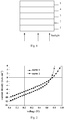
- the polymer solar cell of the present invention comprises a glass substrate 1, a cathode 2, an electronic buffer layer 3, an active layer 4 and an anode 5.
- Fig. 1 shows the structure of the polymer solar cell of the present invention.
- the structure of the polymer solar cell of this embodiment can be described as: Glass substrate/Al/Cs 2 CO 3 /(P3HT:PCBM)/ (ZnO:PEDOT:PSS).
- ZnO:PEDOT:PSS means that the anode is prepared by mixing PEDOT and PSS with ZnO.
- P3HT:PCBM means that material of the active layer includes P3HT and PCBM.
- a commonly encountered polymer solar cell was prepared.
- Structure of the comparative cell can be described as ITO/(PEDOT:PSS)/(P3HT:PCBM)/Cs 2 CO 3 /Al.
- PEDOT:PSS means that material of the hole buffer layer includes PEDOT and PSS.
- P3HT:PCBM means the material of the active layer includes P3HT and PCBM.
- Anode used herein was ITO, i.e. indium tin oxide. Thickness of ITO layer was 120nm.
- Material of the hole buffer layer was mixture of PEDOT and PSS.
- the hole buffer layer was prepared as follows.
- PEDOT and PSS in a ratio of 5:1 (by weight) were dissolved with water to produce an aqueous solution of PEDOT and PSS, where a mass percentage of PEDOT was 5%.
- the aqueous solution was then coated on the cathode by spin-coating at a speed of 5000 rpm for 15s. After drying, a hole buffer layer was obtained.
- the thickness of the buffer layer was 80nm.
- An active layer was prepared in a corresponding manner as described in Example 1. Thickness of the active layer was 200nm.
- An electronic buffer layer was prepared in a corresponding manner as described in Example 1. Material of the electronic buffer layer was Cs 2 CO 3 , and thickness of the electronic buffer layer was 2nm.
- a cathode was prepared in a corresponding manner as described in Example 1. Material of the cathode was Al, and thickness of the cathode was 80nm. By comparison, the present invention uses a reversed structure.
- Anode of the present invention is prepared by mixing hole buffer material with ZnO. The anode is able to act as a hole buffer layer and anode per se, which greatly simplifies the preparation process.
- a method for preparing polymer solar cell comprises the following steps.
- glass was cut into the size of 2 ⁇ 2cm and the luminous area was 0.3 ⁇ 0.3cm. The glass was then sonicated successively with detergent, deionized water, acetone, ethanol and isopropanol for 15 minutes to remove the organic pollutant on the surface of the glass.
- a cathode of Ag and an electronic buffer layer of LiF were deposited successively on the glass by using a high vacuum deposition device (Shenyang Scientific Instrument Development Center Co., Ltd. China. Pressure ⁇ 1 ⁇ 10 -3 Pa).
- Cathode was deposited under a pressure of 5 ⁇ 10 -3 Pa at a speed of 10 nm/s.
- Thickness of the cathode was 10 nm.
- Electronic buffer layer was deposited under a pressure of 5 ⁇ 10 -3 Pa at a speed of 1 nm/s. Thickness of the electronic buffer layer was 0.7 nm.
- Molecular weight of PEDOT is in a range of 13000-50000.
- a weight of PEDOT and PSS are in a ratio 2:1, and the solution comprises 1% by weight of PEDOT.
- a weight of ZnO and PEDOT are in a ratio 6:1. According to a volume ratio of 1:10, the ZnO solution is mixed with the solution of PEDOT and PSS to obtain a second mixed solution.
- the second mixed solution was spin coated on the active layer at a speed of 2000 rpm for 60 s. After that, this was dried in nitrogen gas atmosphere at 50°C for 30 minutes to obtain an anode. Thickness of the anode was 100 nm.
- a polymer solar cell of the present invention was made.
- the polymer solar cell of the present invention comprises a glass substrate, a cathode, an electronic buffer layer, an active layer and an anode.
- the structure of the polymer solar cell of this embodiment can be described as: Glass substrate/Ag/LiF/(P3HT:PCBM)/ (ZnO:PEDOT:PSS).
- ZnO:PEDOT:PSS means that the anode was prepared by mixing PEDOT and PSS with ZnO.
- P3HT:PCBM means that material of the active layer includes P3HT and PCBM.
- a method for preparing polymer solar cell comprises the following steps.
- glass was cut into the size of 2 ⁇ 2cm and the luminous area was 0.3 ⁇ 0.3cm. The glass was then sonicated successively with detergent, deionized water, acetone, ethanol and isopropanol for 15 minutes to remove the organic pollutant on the surface of the glass.
- a cathode of Au and an electronic buffer layer of Cs 2 CO 3 were deposited successively on the glass by using a high vacuum deposition device (Shenyang Scientific Instrument Development Center Co., Ltd. China. Pressure ⁇ 1 ⁇ 10 -3 Pa).
- Cathode was deposited under a pressure of 2 ⁇ 10 -5 Pa at a speed of 1 nm/s.
- Thickness of the cathode was 30 nm.
- Electronic buffer layer was deposited under a pressure of 2 ⁇ 10 -5 Pa at a speed of 0.1 nm/s. Thickness of the electronic buffer layer was 0.5 nm.
- Molecular weight of PEDOT is in a range of 13000-50000.
- a weight of PEDOT and PSS are in a ratio 6:1, and the solution comprises 5% by weight of PEDOT.
- a weight of ZnO and PEDOT are in a ratio 0.75:1. According to a volume ratio of 3:4, the ZnO solution is mixed with the solution of PEDOT and PSS to obtain a second mixed solution.
- the second mixed solution was spin coated on the active layer at a speed of 6000 rpm for 10 s. After that, this was dried in nitrogen gas atmosphere at 200°C for 10 minutes to obtain an anode. Thickness of the anode was 300 nm.
- a polymer solar cell of the present invention was made.
- the polymer solar cell of the present invention comprises a glass substrate, a cathode, an electronic buffer layer, an active layer and an anode.
- the structure of the polymer solar cell of this embodiment can be described as: Glass substrate/Au/Cs 2 CO 3 /(P3HT:PCBM)/ (ZnO:PEDOT:PSS).
- ZnO:PEDOT:PSS means that the anode was prepared by mixing PEDOT and PSS with ZnO.
- P3HT:PCBM means that material of the active layer includes P3HT and PCBM.
- a method for preparing polymer solar cell comprises the following steps.
- glass was cut into the size of 2 ⁇ 2cm and the luminous area was 0.3 ⁇ 0.3cm. The glass was then sonicated successively with detergent, deionized water, acetone, ethanol and isopropanol for 15 minutes to remove the organic pollutant on the surface of the glass.
- a cathode of Pt and an electronic buffer layer of Li 2 CO 3 were deposited successively on the glass by using a high vacuum deposition device (Shenyang Scientific Instrument Development Center Co., Ltd. China. Pressure ⁇ 1 ⁇ 10 -3 Pa).
- Cathode was deposited under a pressure of 5 ⁇ 10 -5 Pa at a speed of 8 nm/s.
- Thickness of the cathode was 12 nm.
- Electronic buffer layer was deposited under a pressure of 5 ⁇ 10 -5 Pa at a speed of 0.5 nm/s. Thickness of the electronic buffer layer was 10 nm.
- Molecular weight of PEDOT is in a range of 13000-50000.
- a weight of PEDOT and PSS are in a ratio 3:1, and the solution comprises 2% by weight of PEDOT.
- a weight of ZnO and PEDOT are in a ratio 4:1. According to a volume ratio of 2:5, the ZnO solution is mixed with the solution of PEDOT and PSS to obtain a second mixed solution.
- the second mixed solution was spin coated on the active layer at a speed of 2500 rpm for 30 s. After that, this was dried in nitrogen gas atmosphere at 50°C for 20 minutes to obtain an anode. Thickness of the anode was 180 nm.
- a polymer solar cell of the present invention was made.
- the polymer solar cell of the present invention comprises a glass substrate, a cathode, an electronic buffer layer, an active layer and an anode.
- the structure of the polymer solar cell of this embodiment can be described as: Glass substrate/Pt/Li 2 CO 3 /(P3HT:PCBM)/ (ZnO:PEDOT:PSS).
- ZnO:PEDOT:PSS means that the anode was prepared by mixing PEDOT and PSS with ZnO.
- P3HT:PCBM means that material of the active layer includes P3HT and PCBM.
- a current-voltage tester (Keithley instruments Inc. US. model: 2602) and a white light source were used to detect current density of the polymer solar cell while varying the voltage.
- the white light was simulated sunlight produced by a xenon lamp (Osram, 500W) and a light filter (AMI.5).
- Fig. 2 shows current density-voltage curves of the polymer solar cell prepared according to Example 1 and a commonly encountered polymer solar cell, corresponding to curve 1 and curve 2, respectively.
- Example 1 shows performances of the polymer solar cell prepared according to Example 1-4 and the comparative cell. The symbol “ ⁇ ” herein is power conversion efficiency. Table 1 performances of the polymer solar cell prepared according to Example 1-4 and the comparative embodiment Solar cell short-circuit current (mA/cm 2 ) open-circuit voltage (V) ⁇ (%) fill factor comparative embodiment 6.18 0.74 1.40 0.31 Example 1 9.46 0.73 2.37 0.34 Example 2 8.00 0.72 1.89 0.33 Example 3 6.51 0.72 1.52 0.32 Example 4 6.65 0.74 1.67 0.34
- short-circuit current and power conversion efficiency of the comparative embodiment are 6.18mA/cm 2 and 1.40%, respectively.
- short-circuit current of the polymer solar cell according to Examples 1-4 is increased to 6.51-9.46mA/cm 2 , and the power conversion efficiency is in a range of 1.52%-2.37%.
- Anode of the present invention is prepared by mixing PEDOT and PSS with ZnO.
- Anode of the polymer solar cell of the present invention has a high electrical conductivity and high injection efficiency. The light is totally reflected back to active layer and absorbed due to the difference of anode and active layer in refractive index, thus improving utilization of the sunlight and increasing power conversion efficiency of polymer solar cell.
- the product and method have industrialized application prospects.
Landscapes
- Physics & Mathematics (AREA)
- Electromagnetism (AREA)
- Engineering & Computer Science (AREA)
- Manufacturing & Machinery (AREA)
- Photovoltaic Devices (AREA)
- Electroluminescent Light Sources (AREA)
- Compositions Of Macromolecular Compounds (AREA)
Description
- The present invention relates to the field of solar cell technique, especially to a polymer solar cell and preparation method thereof.
- In 1982, Weinberger et al. studied photovoltaic properties of polyacetylene and produced a first significant solar cell. However, it had an extremely low photoelectric conversion efficiency of 10-3%. Glenis et al. then produced various polythiophene solar cells, but a common problem was low open-circuit voltage and low photoelectric conversion efficiency. Until 1986, C.W.Tang et al. greatly increased photoelectric current by introducing p-type semiconductor and n-type semiconductor into a double layer solar cell for the first time. This is a landmark in the history of development of organic polymer solar cell.
- A double layer polymer solar cell comprises a positive electrode, a negative electrole and a thin film having photic activity between them. The thin film is active layer. Normally, active layer has a heterogeneous structure consisting of donor (D) and acceptor (A). Main material of donor comprises CdSe, n-polymer, C60 and its derivative PCBM. A solar cell of PCBM could adopt indium tin oxide (ITO) and metal having relatively low work function as positive electrode and negative electrode, respectively. Active layer is generally obtained by mixing conjugated polymer with PCBM. In the case that the light travels through a transparent ITO and reaches conjugated polymer molecules, an exciton can form when photon energy is larger than bandgap of polymer. The exciton moves towards the interface of donor-acceptor (D/A). The difference between D/A is larger than the binding energy of the exciton, which will lead to the separation of excitons at the interface. PCBM transports electrons to the negative electrode, whereas polymer transports holes to the positive electrode ITO, thus generating photoelectric current and photovoltage.
- To increase power conversion efficiency, absorption of sunlight has been normally improved by the modification of structure of material of active layer. But this method has some drawbacks, such as high cost and time-consuming. Furthermore, when the sunlight reaches the active layer, only a small amount of the light can be absorbed and utilized. Most of the sunlight passes through the cell without being utilized. Therefore, an important way to improve utilization of sunlight and increase power conversion efficiency is to improve component or structure of polymer solar cell. However, little related research has been done and reported. Semaltianos et al., Chemical Physics Letters 484 (2010) 283-289 describes modification of the electrical properties of PEDOT:PSS by the incorporation of ZnO nanoparticles synthesized by laser ablation.
US 2011/0139253 A describes an organic photoelectric conversion element an organic photoelectric layer sandwiched between a first and a second electrode.WO 95/04704 - In order to solve the above problems, the present invention aims to provide a method for preparing polymer solar cell. Anode of the polymer solar cell of the present invention is prepared by mixing poly(3,4-ethylenedioxythiophene) (PEDOT) and polystyrene sulfonate (PSS) with zinc oxide (ZnO). Difference between anode and active layer in refractive index causes the sunlight passing through the active layer to be scattered and totally reflected, and then absorbed, thus improving utilization of the sunlight and increasing power conversion efficiency of polymer solar cell.
- The present invention further provides a polymer solar cell prepared by the above method.
- In a first aspect, the present invention provides a method for preparing polymer solar cell, comprising:
- providing a clean glass substrate and then preparing a cathode, an electronic buffer layer and an active layer successively on the glass substrate;
- preparing an anode on the active layer by the following steps:
- dissolving poly(3,4-ethylenedioxythiophene) (PEDOT) and polystyrene sulfonate (PSS) in chlorobenzene to obtain a solution of poly(3,4-ethylenedioxythiophene) and polystyrene sulfonate, where a weight of poly(3,4-ethylenedioxythiophene) and polystyrene sulfonate are in a ratio 2:1-6:1, and a percentage of poly(3,4-ethylenedioxythiophene) by weight of the solution of poly(3,4-ethylenedioxythiophene) and polystyrene sulfonate is in a range of 1%-5%;
- dissolving zinc oxide in acetic acid to obtain a zinc oxide solution with a concentration of 0.05g/ml-0.6g/ml;
- mixing the zinc oxide solution and the solution of poly(3,4-ethylenedioxythiophene) and polystyrene sulfonate in a volume ratio 1:10-3:4 to obtain a mixed solution, where a weight of zinc oxide and poly(3,4-ethylenedioxythiophene) are in a ratio 0.75:1-6:1;
- spin-coating the mixed solution on the active layer, and then drying to obtain the anode;
- obtaining a polymer solar cell.
- Preferably, a particle size of the zinc oxide is in a range of 50nm-200nm.
- Zinc oxide is dissolved with acetic acid because acetic acid is a weak acid and is less corrosive to glass. Other concentrations of the acetic acid solutions are also permitted for the purpose of dissolving zinc oxide. After dissolving zinc oxide, water should be removed by drying. Concentration of the zinc oxide solution is ratio of the mass of zinc oxide to the volume of acetic acid. Both of density of the zinc oxide solution and density of the solution of poly(3,4-ethylenedioxythiophene) and polystyrene sulfonate are deemed to be 1mg/ml.
- Molecular weight of the PEDOT is in a normal range of 13000-50000.
- Preferably, the step of spin-coating is conducted at a speed of 2000 rpm-6000 rpm for 10 s-60 s.
- Preferably, the step of drying is conducted in an inert atmosphere at a temperature of 50°C-200°C for 10 minutes-30 minutes.
- Preferably, a thickness of the anode is in a range of 100nm-300nm.
- Preferably, the glass substrate is common and commercially available glass.
- Preferably, a material of the cathode is aluminium (Al), silver (Ag), gold (Au) or platinum (Pt). More preferably, material of the cathode is aluminium (Al).
- Preferably, the cathode is prepared by vacuum vapor deposition, and the vapor deposition is conducted at a pressure of 2×10⁻⁵Pa-5×10⁻³Pa at a speed of 1nm/s-10nm/s.
- Preferably, a thickness of the cathode is in a range of 10nm-30nm. More preferably, the thickness of the cathode is 15nm.
- Preferably, a material of the electronic buffer layer is lithium fluoride (LiF), lithium carbonate (Li2CO3) or cesium carbonate (Cs2CO3). More preferably, the material of the electronic buffer layer is cesium carbonate (Cs2CO3).
- Preferably, electronic buffer layer is prepared by vacuum vapor deposition, and the vapor deposition is conducted at a pressure of 2×10⁻⁵Pa-5×10⁻³Pa at a speed of 0.1nm/s-1nm/s.
- More preferably, a thickness of the electronic buffer layer is in a range of 0.5nm-10nm. More preferably, the thickness of the electronic buffer layer is 2nm.
- Preferably, material of the active layer comprises poly(3-hexylthiophene) (P3HT) and [6,6]-phenyl-C61-butyric acid methyl ester (PCBM). [6,6]-phenyl-C61-butyric acid methyl ester which is derived from C60 has a molecular formula of C72H14O2.
- Preparation of an active layer comprises: dissolving poly(3-hexylthiophene) (P3HT) and [6,6]-phenyl-C61-butyric acid methyl ester (PCBM) in a solvent to obtain a mixed solution of poly(3-hexylthiophene) (P3HT) and [6,6]-phenyl-C61-butyric acid methyl ester (PCBM), where a weight of poly(3-hexylthiophene) (P3HT) and [6,6]-phenyl-C61-butyric acid methyl ester (PCBM) are in a ratio 1:0.8-1:4; spin coating the mixed solution on the electronic buffer layer in an inert atmosphere; standing for 24 hours - 48 hours at room temperature to obtain the active layer.
- Preferably, a weight of poly(3-hexylthiophene) (P3HT) and [6,6]-phenyl-C61-butyric acid methyl ester (PCBM) are in a ratio 1:0.8.
- Preferably, preparation of the active layer further comprises a step of annealing at a temperature of 50°C-200°C for 5 minutes-100 minutes.
- Preferably, a concentration of the mixed solution of poly(3-hexylthiophene) (P3HT) and [6,6]-phenyl-C61-butyric acid methyl ester (PCBM) is in a range of 8 mg/ml- 24 mg/ml. More preferably, the concentration of the mixed solution of poly(3-hexylthiophene) and [6,6]-phenyl-C61-butyric acid methyl ester is 18 mg/ml.
- Preferably, after spin-coating the mixed solution, a step of annealing at a temperature of 200°C for 5 minutes is performed.
- Preferably, the step of spin-coating is conducted at a speed of 4000 rpm-6000 rpm for 10 s-30 s.
- Total reflection of the sunlight is realized by controlling ratio and concentration of P3HT and PCBM in active layer, achieving a refractive index of about 1.7.
- Preferably, the solvent is methylbenzene, dimethylbenzene, chlorobenzene or chloroform.
- Preferably, a thickness of the active layer is in a range of 80nm-300nm. More preferably, the thickness of the active layer is 200nm.
- In a second aspect, the present invention provides a polymer solar cell comprising a glass substrate, a cathode, an electronic buffer layer, an active layer and an anode stacked successively; the anode includes poly(3,4-ethylenedioxythiophene) and polystyrene sulfonate mixed with zinc oxide; a weight of zinc oxide and poly(3,4-ethylenedioxythiophene) are in a ratio 0.75:1-6:1, and a weight of poly(3,4-ethylenedioxythiophene) and polystyrene sulfonate are in a ratio 2:1-6:1.
- Preferably, a particle size of the zinc oxide is in a range of 50nm-200nm.
- Preferably, a thickness of the anode is in a range of 100nm-300nm.
- In the anode, zinc oxide is dissolved to ionize zinc. After the step of drying, ionic compound of zinc is formed and acts as a conductor of electricity. PEDOT is able to transport holes, which makes the anode to be able to act as a hole transport layer and anode per se.
- Preferably, a thickness of the anode is in a range of 100nm-300nm.
- Preferably, the glass substrate is common and commercially available glass.
- Preferably, a material of the cathode is aluminium (Al), silver (Ag), gold (Au) or platinum (Pt). More preferably, the material of the cathode is aluminium (Al).
- Preferably, a thickness of the cathode is in a range of 10nm-30nm. More preferably, the thickness of the cathode is 15nm.
- Preferably, a material of the electronic buffer layer is lithium fluoride (LiF), lithium carbonate (Li2CO3) or cesium carbonate (Cs2CO3). More preferably, the material of the electronic buffer layer is cesium carbonate (Cs2CO3).
- More preferably, a thickness of the electronic buffer layer is in a range of 0.5nm-10nm. More preferably, the thickness of the electronic buffer layer is 2nm.
- Preferably, material of the active layer comprises poly(3-hexylthiophene) (P3HT) and [6,6]-phenyl-C61-butyric acid methyl ester (PCBM). [6,6]-phenyl-C61-butyric acid methyl ester which is derived from C60 has a molecular formula of C72H14O2. A weight of P3HT and PCBM are in a ratio 1:0.8-1:4.
- Preferably, the weight of P3HT and PCBM are in the ratio 1:0.8.
- Preferably, a thickness of the active layer is in a range of 80nm-300nm. More preferably, the thickness of the active layer is 200nm.
- One important factor affecting power conversion efficiency of solar cell is utilization of sunlight. Currently, a common method for increasing the absorption of sunlight is to modify the structure of the material of active layer. The present invention improves absorption of sunlight by preparing anode using mixed materials, thus increasing power conversion efficiency of polymer solar cell. The anode of the polymer solar cell of the present invention is prepared by mixing poly(3,4-ethylenedioxythiophene) (PEDOT) and polystyrene sulfonate (PSS) with zinc oxide (ZnO). PEDOT has a refractive index of about 1.5, whereas active layer of the present invention has a refractive index of about 1.7. Difference between anode and active layer in refractive index causes the sunlight passing through the active layer to be scattered and totally reflected, and then absorbed. The anode further contains zinc acetate particles, which have a large particle size and is able to scatter the light, thus improving utilization of the sunlight and increasing power conversion efficiency of polymer solar cell.
- The present inventions providing polymer solar cell and preparation method thereof comprise the following benefits.
- (1) In the polymer solar cell of the present invention, the light is totally reflected back to active layer and absorbed due to the difference of anode and active layer in refractive index. The anode further contains zinc acetate particles, which have a large particle size and is able to scatter the light, thus improving utilization of the light and increasing power conversion efficiency of polymer solar cell.
- (2) ITO glass is usually used as an anode of polymer solar cell. However, indium element may permeate the glass, leading to a reduction of lifetime of polymer solar cell. Further, indium is a high cost rare element of a somewhat toxicity. Anode of the present invention is prepared by mixing poly(3,4-ethylenedioxythiophene) and polystyrene sulfonate with zinc oxide. The present invention has an advantage of low cost and good stability.
- (3) Anode of the polymer solar cell of the present invention has a high electrical conductivity (from PEDOT and Zn ions) and high injection efficiency (from PEDOT). The anode is able to act as a hole buffer layer and anode per se. Preparation of solar cell is greatly simplified by not preparing hole buffer layer and anode separately.
- (4) Some oxidizable metals, such as Al and Ag, are usually used as material of cathode. The polymer solar cell of the present invention uses a reversed structure where an electronic buffer layer, an active layer and an anode are successively prepared on a cathode. This could prevent the cathode from being oxidized and facilitate improving the lifetime of a polymer solar cell and enable the product and method to have industrialized application prospects.
-
-
Fig. 1 shows structure of the polymer solar cell comprising aglass substrate 1, acathode 2, anelectronic buffer layer 3, anactive layer 4 and ananode 5. -
Fig. 2 shows current density-voltage curves of the polymer solar cell prepared according to Example 1 and a commonly encountered polymer solar cell, corresponding tocurve 1 andcurve 2, respectively. - The invention will now be described in detail on the basis of preferred embodiments. It is to be understood that various changes may be made.
- A method for preparing polymer solar cell comprises the following steps.
- (1) After a photolithography process, glass was cut into the size of 2× 2cm and the luminous area was 0.3× 0.3cm. The glass was then sonicated successively with detergent, deionized water, acetone, ethanol and isopropanol for 15 minutes to remove the organic pollutant on the surface of the glass.
- (2) A cathode of Al and an electronic buffer layer of Cs2CO3 were deposited successively on the glass by using a high vacuum deposition device (Shenyang Scientific Instrument Development Center Co., Ltd. China. Pressure<1×10⁻³Pa). Cathode was deposited under a pressure of 5×10⁻⁴Pa at a speed of 5nm/s. Thickness of the cathode was 15 nm. Electronic buffer layer was deposited under a pressure of 5×10⁻⁴Pa at a speed of 0.2nm/s. Thickness of the electronic buffer layer was 2 nm.
- (3) Preparation of active layer. To a stirred 0.5ml of chlorobenzene were added 5 mg of P3HT and 4 mg of PCBM to obtain a mixed solution of P3HT and PCBM with a concentration of 18 mg/ml. In a glove box filled with inert gas, the mixed solution was spin-coated on the electronic buffer layer at a speed of 5000 rpm for 15 s. This was allowed to stand for 24 hours at room temperature, and then annealed at 200°C for 5 minutes to obtain an active layer. Thickness of the active layer was 200 nm.
- (4) Preparation of anode on the active layer. ZnO having a particles size of 100nm was dissolved in acetic acid to obtain a ZnO solution having a concentration of 0.4 g/ml. To chlorobenzene was added PEDOT and PSS to obtain a solution of PEDOT and PSS. Molecular weight of PEDOT is in a range of 13000-50000. In the solution of PEDOT and PSS, a weight of PEDOT and PSS are in a ratio 5:1, and the solution comprises 4% by weight of PEDOT. A weight of ZnO and PEDOT are in a ratio 5:1. According to a volume ratio of 1:2, the ZnO solution is mixed with the solution of PEDOT and PSS to obtain a second mixed solution.
- The second mixed solution was spin coated on the active layer at a speed of 4000 rpm for 20 s. After that, this was dried in nitrogen gas atmosphere at 150°C for 30 minutes to obtain an anode. Thickness of the anode was 250 nm. A polymer solar cell of the present invention was made.
- The polymer solar cell of the present invention comprises a
glass substrate 1, acathode 2, anelectronic buffer layer 3, anactive layer 4 and ananode 5.Fig. 1 shows the structure of the polymer solar cell of the present invention. The structure of the polymer solar cell of this embodiment can be described as: Glass substrate/Al/Cs2CO3/(P3HT:PCBM)/ (ZnO:PEDOT:PSS). (ZnO:PEDOT:PSS) means that the anode is prepared by mixing PEDOT and PSS with ZnO. (P3HT:PCBM) means that material of the active layer includes P3HT and PCBM. - As a comparison, a commonly encountered polymer solar cell was prepared. Structure of the comparative cell can be described as ITO/(PEDOT:PSS)/(P3HT:PCBM)/Cs2CO3/Al. (PEDOT:PSS) means that material of the hole buffer layer includes PEDOT and PSS. (P3HT:PCBM) means the material of the active layer includes P3HT and PCBM. Anode used herein was ITO, i.e. indium tin oxide. Thickness of ITO layer was 120nm. Material of the hole buffer layer was mixture of PEDOT and PSS. The hole buffer layer was prepared as follows. PEDOT and PSS in a ratio of 5:1 (by weight) were dissolved with water to produce an aqueous solution of PEDOT and PSS, where a mass percentage of PEDOT was 5%. The aqueous solution was then coated on the cathode by spin-coating at a speed of 5000 rpm for 15s. After drying, a hole buffer layer was obtained. The thickness of the buffer layer was 80nm. An active layer was prepared in a corresponding manner as described in Example 1. Thickness of the active layer was 200nm. An electronic buffer layer was prepared in a corresponding manner as described in Example 1. Material of the electronic buffer layer was Cs2CO3, and thickness of the electronic buffer layer was 2nm. A cathode was prepared in a corresponding manner as described in Example 1. Material of the cathode was Al, and thickness of the cathode was 80nm. By comparison, the present invention uses a reversed structure. Anode of the present invention is prepared by mixing hole buffer material with ZnO. The anode is able to act as a hole buffer layer and anode per se, which greatly simplifies the preparation process.
- A method for preparing polymer solar cell comprises the following steps.
- (1) After a photolithography process, glass was cut into the size of 2× 2cm and the luminous area was 0.3× 0.3cm. The glass was then sonicated successively with detergent, deionized water, acetone, ethanol and isopropanol for 15 minutes to remove the organic pollutant on the surface of the glass.
- (2) A cathode of Ag and an electronic buffer layer of LiF were deposited successively on the glass by using a high vacuum deposition device (Shenyang Scientific Instrument Development Center Co., Ltd. China. Pressure<1×10⁻³Pa). Cathode was deposited under a pressure of 5×10⁻³ Pa at a speed of 10 nm/s. Thickness of the cathode was 10 nm. Electronic buffer layer was deposited under a pressure of 5×10⁻³ Pa at a speed of 1 nm/s. Thickness of the electronic buffer layer was 0.7 nm.
- (3) Preparation of active layer. To a stirred 1ml of chloroform were added 4.8mg of P3HT and 19.2mg of PCBM to obtain a mixed solution of P3HT and PCBM with a concentration of 24mg/ml. In a glove box filled with inert gas, the mixed solution was spin-coated on the electronic buffer layer at a speed of 4000 rpm for 30 s. This was allowed to stand for 36 hours at room temperature to obtain an active layer. Thickness of the active layer was 80 nm.
- (4) Preparation of anode on the active layer. ZnO having a particles size of 200 nm was dissolved in acetic acid to obtain a ZnO solution having a concentration of 0.6g/ml. To chlorobenzene were added PEDOT and PSS to obtain a solution of PEDOT and PSS.
- Molecular weight of PEDOT is in a range of 13000-50000. In the solution of PEDOT and PSS, a weight of PEDOT and PSS are in a ratio 2:1, and the solution comprises 1% by weight of PEDOT. A weight of ZnO and PEDOT are in a ratio 6:1. According to a volume ratio of 1:10, the ZnO solution is mixed with the solution of PEDOT and PSS to obtain a second mixed solution.
- The second mixed solution was spin coated on the active layer at a speed of 2000 rpm for 60 s. After that, this was dried in nitrogen gas atmosphere at 50°C for 30 minutes to obtain an anode. Thickness of the anode was 100 nm. A polymer solar cell of the present invention was made.
- The polymer solar cell of the present invention comprises a glass substrate, a cathode, an electronic buffer layer, an active layer and an anode. The structure of the polymer solar cell of this embodiment can be described as: Glass substrate/Ag/LiF/(P3HT:PCBM)/ (ZnO:PEDOT:PSS). (ZnO:PEDOT:PSS) means that the anode was prepared by mixing PEDOT and PSS with ZnO. (P3HT:PCBM) means that material of the active layer includes P3HT and PCBM.
- A method for preparing polymer solar cell comprises the following steps.
- (1) After a photolithography process, glass was cut into the size of 2× 2cm and the luminous area was 0.3× 0.3cm. The glass was then sonicated successively with detergent, deionized water, acetone, ethanol and isopropanol for 15 minutes to remove the organic pollutant on the surface of the glass.
- (2) A cathode of Au and an electronic buffer layer of Cs2CO3 were deposited successively on the glass by using a high vacuum deposition device (Shenyang Scientific Instrument Development Center Co., Ltd. China. Pressure<1×10⁻³Pa). Cathode was deposited under a pressure of 2×10⁻⁵ Pa at a speed of 1 nm/s. Thickness of the cathode was 30 nm. Electronic buffer layer was deposited under a pressure of 2×10⁻⁵ Pa at a speed of 0.1 nm/s. Thickness of the electronic buffer layer was 0.5 nm.
- (3) Preparation of active layer. To a stirred 1ml of chloroform were added 4mg of P3HT and 12mg of PCBM to obtain a mixed solution of P3HT and PCBM with a concentration of 16mg/ml. In a glove box filled with inert gas, the mixed solution was spin-coated on the electronic buffer layer at a speed of 6000 rpm for 10 s. This was allowed to stand for 20 hours at room temperature, and then annealed at 100°C for 100 minutes to obtain an active layer. Thickness of the active layer was 200 nm.
- (4) Preparation of anode on the active layer. ZnO having a particles size of 50 nm was dissolved in acetic acid to obtain a ZnO solution having a concentration of 0.05g/ml. To chlorobenzene were added PEDOT and PSS to obtain a solution of PEDOT and PSS.
- Molecular weight of PEDOT is in a range of 13000-50000. In the solution of PEDOT and PSS, a weight of PEDOT and PSS are in a ratio 6:1, and the solution comprises 5% by weight of PEDOT. A weight of ZnO and PEDOT are in a ratio 0.75:1. According to a volume ratio of 3:4, the ZnO solution is mixed with the solution of PEDOT and PSS to obtain a second mixed solution.
- The second mixed solution was spin coated on the active layer at a speed of 6000 rpm for 10 s. After that, this was dried in nitrogen gas atmosphere at 200°C for 10 minutes to obtain an anode. Thickness of the anode was 300 nm. A polymer solar cell of the present invention was made.
- The polymer solar cell of the present invention comprises a glass substrate, a cathode, an electronic buffer layer, an active layer and an anode. The structure of the polymer solar cell of this embodiment can be described as: Glass substrate/Au/Cs2CO3/(P3HT:PCBM)/ (ZnO:PEDOT:PSS). (ZnO:PEDOT:PSS) means that the anode was prepared by mixing PEDOT and PSS with ZnO. (P3HT:PCBM) means that material of the active layer includes P3HT and PCBM.
- A method for preparing polymer solar cell comprises the following steps.
- (1) After a photolithography process, glass was cut into the size of 2× 2cm and the luminous area was 0.3× 0.3cm. The glass was then sonicated successively with detergent, deionized water, acetone, ethanol and isopropanol for 15 minutes to remove the organic pollutant on the surface of the glass.
- (2) A cathode of Pt and an electronic buffer layer of Li2CO3 were deposited successively on the glass by using a high vacuum deposition device (Shenyang Scientific Instrument Development Center Co., Ltd. China. Pressure<1×10⁻³Pa). Cathode was deposited under a pressure of 5×10⁻⁵ Pa at a speed of 8 nm/s. Thickness of the cathode was 12 nm. Electronic buffer layer was deposited under a pressure of 5×10⁻⁵ Pa at a speed of 0.5 nm/s. Thickness of the electronic buffer layer was 10 nm.
- (3) Preparation of active layer. To a stirred 1ml of chloroform were added 2.67mg of P3HT and 5.33mg of PCBM to obtain a mixed solution of P3HT and PCBM with a concentration of 8mg/ml. In a glove box filled with inert gas, the mixed solution was spin-coated on the electronic buffer layer at a speed of 5000 rpm for 20 s. This was allowed to stand for 48 hours at room temperature, and then annealed at 70°C for 100 minutes to obtain an active layer. Thickness of the active layer was 300 nm.
- (4) Preparation of anode on the active layer. ZnO having a particles size of 80 nm was dissolved in acetic acid to obtain a ZnO solution having a concentration of 0.2g/ml. To chlorobenzene were added PEDOT and PSS to obtain a solution of PEDOT and PSS.
- Molecular weight of PEDOT is in a range of 13000-50000. In the solution of PEDOT and PSS, a weight of PEDOT and PSS are in a ratio 3:1, and the solution comprises 2% by weight of PEDOT. A weight of ZnO and PEDOT are in a ratio 4:1. According to a volume ratio of 2:5, the ZnO solution is mixed with the solution of PEDOT and PSS to obtain a second mixed solution.
- The second mixed solution was spin coated on the active layer at a speed of 2500 rpm for 30 s. After that, this was dried in nitrogen gas atmosphere at 50°C for 20 minutes to obtain an anode. Thickness of the anode was 180 nm. A polymer solar cell of the present invention was made.
- The polymer solar cell of the present invention comprises a glass substrate, a cathode, an electronic buffer layer, an active layer and an anode. The structure of the polymer solar cell of this embodiment can be described as: Glass substrate/Pt/Li2CO3/(P3HT:PCBM)/ (ZnO:PEDOT:PSS). (ZnO:PEDOT:PSS) means that the anode was prepared by mixing PEDOT and PSS with ZnO. (P3HT:PCBM) means that material of the active layer includes P3HT and PCBM.
- A current-voltage tester (Keithley instruments Inc. US. model: 2602) and a white light source were used to detect current density of the polymer solar cell while varying the voltage. The white light was simulated sunlight produced by a xenon lamp (Osram, 500W) and a light filter (AMI.5).
Fig. 2 shows current density-voltage curves of the polymer solar cell prepared according to Example 1 and a commonly encountered polymer solar cell, corresponding tocurve 1 andcurve 2, respectively. - Current density of the polymer solar cell prepared according to Example 2-4 were detected while varying voltage. Some performance data, such as short-circuit current, open-circuit voltage, power conversion efficiency and fill factor, were obtained and shown in Table. 1. Table 1 shows performances of the polymer solar cell prepared according to Example 1-4 and the comparative cell. The symbol "η" herein is power conversion efficiency.
Table 1 performances of the polymer solar cell prepared according to Example 1-4 and the comparative embodiment Solar cell short-circuit current (mA/cm2) open-circuit voltage (V) η(%) fill factor comparative embodiment 6.18 0.74 1.40 0.31 Example 1 9.46 0.73 2.37 0.34 Example 2 8.00 0.72 1.89 0.33 Example 3 6.51 0.72 1.52 0.32 Example 4 6.65 0.74 1.67 0.34 - It can be seen from Table 1 that short-circuit current and power conversion efficiency of the comparative embodiment are 6.18mA/cm2 and 1.40%, respectively. However, short-circuit current of the polymer solar cell according to Examples 1-4 is increased to 6.51-9.46mA/cm2, and the power conversion efficiency is in a range of 1.52%-2.37%. It indicates that the present invention uses a reversed structure. Anode of the present invention is prepared by mixing PEDOT and PSS with ZnO. Anode of the polymer solar cell of the present invention has a high electrical conductivity and high injection efficiency. The light is totally reflected back to active layer and absorbed due to the difference of anode and active layer in refractive index, thus improving utilization of the sunlight and increasing power conversion efficiency of polymer solar cell. The product and method have industrialized application prospects.
Claims (10)
- A method for preparing polymer solar cell, comprising:providing a clean glass substrate and then preparing a cathode, an electronic buffer layer and an active layer successively on the glass substrate;preparing an anode on the active layer by the following steps:dissolving poly(3,4-ethylenedioxythiophene) and polystyrene sulfonate in chlorobenzene to obtain a solution of poly(3,4-ethylenedioxythiophene) and polystyrene sulfonate, where a weight of poly(3,4-ethylenedioxythiophene) and polystyrene sulfonate are in a ratio 2:1-6:1, and a percentage of poly(3,4-ethylenedioxythiophene) by weight of the solution of poly(3,4-ethylenedioxythiophene) and polystyrene sulfonate is in a range of 1%-5%;dissolving zinc oxide in acetic acid to obtain a zinc oxide solution with a concentration of 0.05g/ml-0.6g/ml;mixing the zinc oxide solution and the solution of poly(3,4-ethylenedioxythiophene) and polystyrene sulfonate in a volume ratio 1:10-3:4 to obtain a mixed solution, where a weight of zinc oxide and poly(3,4-ethylenedioxythiophene) are in a ratio 0.75:1-6:1;spin-coating the mixed solution on the active layer, and then drying to obtain the anode;obtaining a polymer solar cell.
- The method for preparing polymer solar cell of claim 1, wherein a particle size of the zinc oxide is in a range of 50nm-200nm.
- The method for preparing polymer solar cell of claim 1, wherein the step of spin-coating is conducted at a speed of 2000 rpm-6000 rpm for 10 s-60 s.
- The method for preparing polymer solar cell of claim 1, wherein the step of drying is conducted in an inert atmosphere at a temperature of 50°C-200°C for 10 minutes-30 minutes.
- The method for preparing polymer solar cell of claim 1, wherein the step of preparing an active layer comprises:dissolving poly(3-hexylthiophene) and [6,6]-phenyl-C61-butyric acid methyl ester in a solvent to obtain a mixed solution of poly(3-hexylthiophene) and [6,6]-phenyl-C61-butyric acid methyl ester, where a weight of poly(3-hexylthiophene) and [6,6]-phenyl-C61-butyric acid methyl ester are in a ratio 1:0.8-1:4;spin-coating the mixed solution of poly(3-hexylthiophene) and [6,6]-phenyl-C61-butyric acid methyl ester on the electronic buffer layer in an inert atmosphere;standing for 24 hours - 48 hours at room temperature to obtain the active layer.
- The method for preparing polymer solar cell of claim 5, wherein the step of preparing the active layer further comprises a step of annealing at a temperature of 50°C-200°C for 5 minutes-100 minutes.
- The method for preparing polymer solar cell of claim 5, wherein a concentration of the mixed solution of poly(3-hexylthiophene) and [6,6]-phenyl-C61-butyric acid methyl ester is in a range of 8 mg/ml- 24 mg/ml.
- The method for preparing polymer solar cell of claim 5, wherein the step of spin-coating is conducted at a speed of 4000 rpm-6000 rpm for 10 s-30 s.
- A polymer solar cell comprising a glass substrate, a cathode, an electronic buffer layer, an active layer and an anode stacked successively; the anode includes poly(3,4-ethylenedioxythiophene) and polystyrene sulfonate mixed with zinc oxide and zinc acetate; a weight of zinc oxide and poly(3,4-ethylenedioxythiophene) are in a ratio 0.75:1-6:1, and a weight of poly(3,4-ethylenedioxythiophene) and polystyrene sulfonate are in a ratio 2:1-6:1.
- The polymer solar cell of claim 9, wherein a particle size of zinc oxide is in a range of 50nm-200nm; a thickness of the anode is in a range of 100 nm-300 nm.
Applications Claiming Priority (1)
| Application Number | Priority Date | Filing Date | Title |
|---|---|---|---|
| PCT/CN2012/082257 WO2014047859A1 (en) | 2012-09-28 | 2012-09-28 | Polymer solar cell and preparation method thereof |
Publications (3)
| Publication Number | Publication Date |
|---|---|
| EP2903029A1 EP2903029A1 (en) | 2015-08-05 |
| EP2903029A4 EP2903029A4 (en) | 2016-05-25 |
| EP2903029B1 true EP2903029B1 (en) | 2017-12-27 |
Family
ID=50386835
Family Applications (1)
| Application Number | Title | Priority Date | Filing Date |
|---|---|---|---|
| EP12885934.5A Active EP2903029B1 (en) | 2012-09-28 | 2012-09-28 | Polymer solar cell and preparation method thereof |
Country Status (5)
| Country | Link |
|---|---|
| US (1) | US20150263285A1 (en) |
| EP (1) | EP2903029B1 (en) |
| JP (1) | JP2015532524A (en) |
| CN (1) | CN104662671B (en) |
| WO (1) | WO2014047859A1 (en) |
Families Citing this family (7)
| Publication number | Priority date | Publication date | Assignee | Title |
|---|---|---|---|---|
| US20170125735A1 (en) * | 2015-10-30 | 2017-05-04 | National Taiwan University | Electroluminescent device |
| CN106711332A (en) * | 2016-12-19 | 2017-05-24 | 李瑞锋 | Dual-ball optical active layer organic thin-film solar cell and manufacturing method thereof |
| KR102064650B1 (en) * | 2017-05-02 | 2020-01-09 | 주식회사 엘지화학 | The method for manufacturing of organic solar cell and organic solar cell thereby |
| CN109888099A (en) * | 2018-12-11 | 2019-06-14 | 西安理工大学 | Quaternary wide-spectrum high-ratio detectivity organic photodetector and preparation method thereof |
| CN114316223B (en) * | 2021-12-31 | 2022-09-27 | 华中科技大学 | Alcohol dispersion liquid of conductive polyethylene dioxythiophene and preparation method and application thereof |
| CN114725288B (en) * | 2022-04-08 | 2025-08-05 | 浙江大学 | Organic solar cell based on self-assembled complex modified anode and preparation method thereof |
| CN116063321B (en) * | 2023-03-30 | 2023-06-13 | 南方科技大学 | A kind of receptor material and its synthesis method and application |
Family Cites Families (18)
| Publication number | Priority date | Publication date | Assignee | Title |
|---|---|---|---|---|
| JPH06227814A (en) * | 1993-02-01 | 1994-08-16 | Nippon Steel Corp | Method for producing high-purity zinc oxide powder |
| GB9316437D0 (en) * | 1993-08-06 | 1993-09-22 | Harcros Chemicals Uk Limited | Zinc oxide and a process for making it |
| JP2003069061A (en) * | 2001-08-24 | 2003-03-07 | Sharp Corp | Multilayer photoelectric conversion element |
| JP4534674B2 (en) * | 2004-08-31 | 2010-09-01 | 日産自動車株式会社 | Functional thin film element, method for producing functional thin film element, and article using functional thin film element |
| JP4925224B2 (en) * | 2006-03-31 | 2012-04-25 | 独立行政法人産業技術総合研究所 | Organic compound and semiconductor thin film electrode, photoelectric conversion element and photoelectrochemical solar cell using the same |
| JP2008078491A (en) * | 2006-09-22 | 2008-04-03 | Nissan Motor Co Ltd | Optical functional thin film element, method for manufacturing optical functional thin film element, and article |
| CN101978525A (en) * | 2008-03-25 | 2011-02-16 | 住友化学株式会社 | Organic photoelectric conversion element |
| CN101635332A (en) * | 2008-07-22 | 2010-01-27 | 厦门市东林电子有限公司 | P-type doped organic film prepared by wet method and electroluminescent device provided with same |
| WO2011004807A1 (en) * | 2009-07-10 | 2011-01-13 | コニカミノルタホールディングス株式会社 | Organic photoelectric conversion element, solar cell using same, and optical sensor array |
| CN101640133B (en) * | 2009-08-24 | 2012-05-23 | 中国科学院长春应用化学研究所 | Polymer/inorganic nano-crystal hybrid solar cell and manufacture method thereof |
| JP5362017B2 (en) * | 2009-09-09 | 2013-12-11 | 株式会社東芝 | Organic thin film solar cell |
| US8664518B2 (en) * | 2009-12-11 | 2014-03-04 | Konica Minolta Holdngs, Inc. | Organic photoelectric conversion element and producing method of the same |
| JP2011134775A (en) * | 2009-12-22 | 2011-07-07 | Mitsubishi Chemicals Corp | Solar battery |
| CN102142521A (en) * | 2010-01-29 | 2011-08-03 | 海洋王照明科技股份有限公司 | Organic solar battery and preparation method thereof |
| CN102456839A (en) * | 2010-10-21 | 2012-05-16 | 海洋王照明科技股份有限公司 | Organic electroluminescent device and preparation method thereof |
| CN102148332B (en) * | 2010-11-26 | 2012-02-01 | 北京化工大学 | Preparation method of semiconductor nanowire-based organic/inorganic composite solar cell |
| CN102683602B (en) * | 2011-03-14 | 2015-03-11 | 海洋王照明科技股份有限公司 | Inverted type transparent organic electroluminescent device and preparation method thereof |
| CN102568840B (en) * | 2011-12-23 | 2014-02-12 | 彩虹集团公司 | Preparation method of counter electrode of dye sensitization battery |
-
2012
- 2012-09-28 WO PCT/CN2012/082257 patent/WO2014047859A1/en not_active Ceased
- 2012-09-28 EP EP12885934.5A patent/EP2903029B1/en active Active
- 2012-09-28 US US14/431,993 patent/US20150263285A1/en not_active Abandoned
- 2012-09-28 CN CN201280075953.3A patent/CN104662671B/en active Active
- 2012-09-28 JP JP2015533396A patent/JP2015532524A/en active Pending
Non-Patent Citations (1)
| Title |
|---|
| None * |
Also Published As
| Publication number | Publication date |
|---|---|
| EP2903029A4 (en) | 2016-05-25 |
| CN104662671B (en) | 2017-03-08 |
| EP2903029A1 (en) | 2015-08-05 |
| WO2014047859A1 (en) | 2014-04-03 |
| US20150263285A1 (en) | 2015-09-17 |
| CN104662671A (en) | 2015-05-27 |
| JP2015532524A (en) | 2015-11-09 |
Similar Documents
| Publication | Publication Date | Title |
|---|---|---|
| Qian et al. | Hybrid polymer-CdSe solar cells with a ZnO nanoparticle buffer layer for improved efficiency and lifetime | |
| US8044389B2 (en) | Polymer electronic devices by all-solution process | |
| EP2903029A1 (en) | Polymer solar cell and preparation method thereof | |
| CN108767118A (en) | A kind of ternary all-polymer solar cell | |
| Lee et al. | Investigation of PCBM/ZnO and C60/BCP-based electron transport layer for high-performance pin perovskite solar cells | |
| Dai et al. | Performance improvement of polymer solar cells with binary additives induced morphology optimization and interface modification simultaneously | |
| Ameen et al. | Solution processed transition metal oxide anode buffer layers for efficiency and stability enhancement of polymer solar cells | |
| Wen et al. | Environmentally friendly cathode interlayer modification on edible bio‐acids with enhanced electron extraction and improved power conversion efficiency | |
| CN101123296A (en) | A kind of polymer solar cell and preparation method thereof | |
| Liu et al. | Improving the efficiency of inverted polymer solar cells by introducing inorganic dopants | |
| Swart et al. | P3HT: PCBM based solar cells: A short review focusing on ZnO nanoparticles buffer layer, post-fabrication annealing and an inverted geometry | |
| CN104011892B (en) | High polymer solar cell device and preparation method thereof | |
| EP2787547A1 (en) | Polymer solar cell and method for preparing same | |
| Jia et al. | Improved longtime stability of highly efficient polymer solar cells by accurately self-formed metal oxide interlayer at metal electrode | |
| Lu et al. | Polymer solar cells based on spontaneously-spreading film with double electron-transporting layers | |
| CN101640133B (en) | Polymer/inorganic nano-crystal hybrid solar cell and manufacture method thereof | |
| Zhang et al. | Preparation and employment of carbon nanodots to improve electron extraction capacity of polyethylenimine interfacial layer for polymer solar cells | |
| CN103137871A (en) | Polymer solar energy cell and preparation method thereof | |
| CN103296222B (en) | A kind of polymer solar battery cathodic modification material | |
| CN102956826A (en) | Polymer solar battery and preparation method thereof | |
| Yap et al. | Effect of organic salt doping on the performance of single layer bulk heterojunction organic solar cell | |
| CN102270740B (en) | Organic photoelectric semiconductor element and manufacturing method thereof | |
| CN102810641B (en) | A kind of polymer solar battery and preparation method thereof | |
| CN104966782B (en) | A kind of polymer solar battery cathodic modification material and preparation method thereof | |
| CN103137870A (en) | Polymer solar energy cell and preparation method thereof |
Legal Events
| Date | Code | Title | Description |
|---|---|---|---|
| PUAI | Public reference made under article 153(3) epc to a published international application that has entered the european phase |
Free format text: ORIGINAL CODE: 0009012 |
|
| 17P | Request for examination filed |
Effective date: 20150325 |
|
| AK | Designated contracting states |
Kind code of ref document: A1 Designated state(s): AL AT BE BG CH CY CZ DE DK EE ES FI FR GB GR HR HU IE IS IT LI LT LU LV MC MK MT NL NO PL PT RO RS SE SI SK SM TR |
|
| AX | Request for extension of the european patent |
Extension state: BA ME |
|
| DAX | Request for extension of the european patent (deleted) | ||
| REG | Reference to a national code |
Ref country code: DE Ref legal event code: R079 Ref document number: 602012041484 Country of ref document: DE Free format text: PREVIOUS MAIN CLASS: H01L0031000000 Ipc: H01L0051420000 |
|
| RA4 | Supplementary search report drawn up and despatched (corrected) |
Effective date: 20160428 |
|
| RIC1 | Information provided on ipc code assigned before grant |
Ipc: H01L 31/00 20060101ALI20160421BHEP Ipc: H01G 9/20 20060101ALI20160421BHEP Ipc: H01L 51/44 20060101ALI20160421BHEP Ipc: H01L 51/42 20060101AFI20160421BHEP |
|
| GRAP | Despatch of communication of intention to grant a patent |
Free format text: ORIGINAL CODE: EPIDOSNIGR1 |
|
| INTG | Intention to grant announced |
Effective date: 20170830 |
|
| GRAS | Grant fee paid |
Free format text: ORIGINAL CODE: EPIDOSNIGR3 |
|
| GRAA | (expected) grant |
Free format text: ORIGINAL CODE: 0009210 |
|
| AK | Designated contracting states |
Kind code of ref document: B1 Designated state(s): AL AT BE BG CH CY CZ DE DK EE ES FI FR GB GR HR HU IE IS IT LI LT LU LV MC MK MT NL NO PL PT RO RS SE SI SK SM TR |
|
| REG | Reference to a national code |
Ref country code: GB Ref legal event code: FG4D |
|
| REG | Reference to a national code |
Ref country code: CH Ref legal event code: EP |
|
| REG | Reference to a national code |
Ref country code: AT Ref legal event code: REF Ref document number: 959009 Country of ref document: AT Kind code of ref document: T Effective date: 20180115 |
|
| REG | Reference to a national code |
Ref country code: IE Ref legal event code: FG4D |
|
| REG | Reference to a national code |
Ref country code: DE Ref legal event code: R096 Ref document number: 602012041484 Country of ref document: DE |
|
| REG | Reference to a national code |
Ref country code: NL Ref legal event code: FP |
|
| PG25 | Lapsed in a contracting state [announced via postgrant information from national office to epo] |
Ref country code: NO Free format text: LAPSE BECAUSE OF FAILURE TO SUBMIT A TRANSLATION OF THE DESCRIPTION OR TO PAY THE FEE WITHIN THE PRESCRIBED TIME-LIMIT Effective date: 20180327 Ref country code: FI Free format text: LAPSE BECAUSE OF FAILURE TO SUBMIT A TRANSLATION OF THE DESCRIPTION OR TO PAY THE FEE WITHIN THE PRESCRIBED TIME-LIMIT Effective date: 20171227 Ref country code: LT Free format text: LAPSE BECAUSE OF FAILURE TO SUBMIT A TRANSLATION OF THE DESCRIPTION OR TO PAY THE FEE WITHIN THE PRESCRIBED TIME-LIMIT Effective date: 20171227 |
|
| REG | Reference to a national code |
Ref country code: LT Ref legal event code: MG4D |
|
| REG | Reference to a national code |
Ref country code: AT Ref legal event code: MK05 Ref document number: 959009 Country of ref document: AT Kind code of ref document: T Effective date: 20171227 |
|
| PG25 | Lapsed in a contracting state [announced via postgrant information from national office to epo] |
Ref country code: RS Free format text: LAPSE BECAUSE OF FAILURE TO SUBMIT A TRANSLATION OF THE DESCRIPTION OR TO PAY THE FEE WITHIN THE PRESCRIBED TIME-LIMIT Effective date: 20171227 Ref country code: HR Free format text: LAPSE BECAUSE OF FAILURE TO SUBMIT A TRANSLATION OF THE DESCRIPTION OR TO PAY THE FEE WITHIN THE PRESCRIBED TIME-LIMIT Effective date: 20171227 Ref country code: BG Free format text: LAPSE BECAUSE OF FAILURE TO SUBMIT A TRANSLATION OF THE DESCRIPTION OR TO PAY THE FEE WITHIN THE PRESCRIBED TIME-LIMIT Effective date: 20180327 Ref country code: LV Free format text: LAPSE BECAUSE OF FAILURE TO SUBMIT A TRANSLATION OF THE DESCRIPTION OR TO PAY THE FEE WITHIN THE PRESCRIBED TIME-LIMIT Effective date: 20171227 Ref country code: GR Free format text: LAPSE BECAUSE OF FAILURE TO SUBMIT A TRANSLATION OF THE DESCRIPTION OR TO PAY THE FEE WITHIN THE PRESCRIBED TIME-LIMIT Effective date: 20180328 |
|
| PG25 | Lapsed in a contracting state [announced via postgrant information from national office to epo] |
Ref country code: ES Free format text: LAPSE BECAUSE OF FAILURE TO SUBMIT A TRANSLATION OF THE DESCRIPTION OR TO PAY THE FEE WITHIN THE PRESCRIBED TIME-LIMIT Effective date: 20171227 Ref country code: CZ Free format text: LAPSE BECAUSE OF FAILURE TO SUBMIT A TRANSLATION OF THE DESCRIPTION OR TO PAY THE FEE WITHIN THE PRESCRIBED TIME-LIMIT Effective date: 20171227 Ref country code: SK Free format text: LAPSE BECAUSE OF FAILURE TO SUBMIT A TRANSLATION OF THE DESCRIPTION OR TO PAY THE FEE WITHIN THE PRESCRIBED TIME-LIMIT Effective date: 20171227 Ref country code: EE Free format text: LAPSE BECAUSE OF FAILURE TO SUBMIT A TRANSLATION OF THE DESCRIPTION OR TO PAY THE FEE WITHIN THE PRESCRIBED TIME-LIMIT Effective date: 20171227 Ref country code: CY Free format text: LAPSE BECAUSE OF FAILURE TO SUBMIT A TRANSLATION OF THE DESCRIPTION OR TO PAY THE FEE WITHIN THE PRESCRIBED TIME-LIMIT Effective date: 20171227 |
|
| PG25 | Lapsed in a contracting state [announced via postgrant information from national office to epo] |
Ref country code: IS Free format text: LAPSE BECAUSE OF FAILURE TO SUBMIT A TRANSLATION OF THE DESCRIPTION OR TO PAY THE FEE WITHIN THE PRESCRIBED TIME-LIMIT Effective date: 20180427 Ref country code: SM Free format text: LAPSE BECAUSE OF FAILURE TO SUBMIT A TRANSLATION OF THE DESCRIPTION OR TO PAY THE FEE WITHIN THE PRESCRIBED TIME-LIMIT Effective date: 20171227 Ref country code: IT Free format text: LAPSE BECAUSE OF FAILURE TO SUBMIT A TRANSLATION OF THE DESCRIPTION OR TO PAY THE FEE WITHIN THE PRESCRIBED TIME-LIMIT Effective date: 20171227 Ref country code: RO Free format text: LAPSE BECAUSE OF FAILURE TO SUBMIT A TRANSLATION OF THE DESCRIPTION OR TO PAY THE FEE WITHIN THE PRESCRIBED TIME-LIMIT Effective date: 20171227 Ref country code: PL Free format text: LAPSE BECAUSE OF FAILURE TO SUBMIT A TRANSLATION OF THE DESCRIPTION OR TO PAY THE FEE WITHIN THE PRESCRIBED TIME-LIMIT Effective date: 20171227 Ref country code: AT Free format text: LAPSE BECAUSE OF FAILURE TO SUBMIT A TRANSLATION OF THE DESCRIPTION OR TO PAY THE FEE WITHIN THE PRESCRIBED TIME-LIMIT Effective date: 20171227 |
|
| REG | Reference to a national code |
Ref country code: DE Ref legal event code: R097 Ref document number: 602012041484 Country of ref document: DE |
|
| PLBE | No opposition filed within time limit |
Free format text: ORIGINAL CODE: 0009261 |
|
| STAA | Information on the status of an ep patent application or granted ep patent |
Free format text: STATUS: NO OPPOSITION FILED WITHIN TIME LIMIT |
|
| PG25 | Lapsed in a contracting state [announced via postgrant information from national office to epo] |
Ref country code: DK Free format text: LAPSE BECAUSE OF FAILURE TO SUBMIT A TRANSLATION OF THE DESCRIPTION OR TO PAY THE FEE WITHIN THE PRESCRIBED TIME-LIMIT Effective date: 20171227 |
|
| 26N | No opposition filed |
Effective date: 20180928 |
|
| PG25 | Lapsed in a contracting state [announced via postgrant information from national office to epo] |
Ref country code: SI Free format text: LAPSE BECAUSE OF FAILURE TO SUBMIT A TRANSLATION OF THE DESCRIPTION OR TO PAY THE FEE WITHIN THE PRESCRIBED TIME-LIMIT Effective date: 20171227 |
|
| PG25 | Lapsed in a contracting state [announced via postgrant information from national office to epo] |
Ref country code: MC Free format text: LAPSE BECAUSE OF FAILURE TO SUBMIT A TRANSLATION OF THE DESCRIPTION OR TO PAY THE FEE WITHIN THE PRESCRIBED TIME-LIMIT Effective date: 20171227 |
|
| REG | Reference to a national code |
Ref country code: CH Ref legal event code: PL |
|
| GBPC | Gb: european patent ceased through non-payment of renewal fee |
Effective date: 20180928 |
|
| REG | Reference to a national code |
Ref country code: BE Ref legal event code: MM Effective date: 20180930 |
|
| REG | Reference to a national code |
Ref country code: IE Ref legal event code: MM4A |
|
| PG25 | Lapsed in a contracting state [announced via postgrant information from national office to epo] |
Ref country code: LU Free format text: LAPSE BECAUSE OF NON-PAYMENT OF DUE FEES Effective date: 20180928 |
|
| PG25 | Lapsed in a contracting state [announced via postgrant information from national office to epo] |
Ref country code: IE Free format text: LAPSE BECAUSE OF NON-PAYMENT OF DUE FEES Effective date: 20180928 |
|
| PG25 | Lapsed in a contracting state [announced via postgrant information from national office to epo] |
Ref country code: BE Free format text: LAPSE BECAUSE OF NON-PAYMENT OF DUE FEES Effective date: 20180930 Ref country code: LI Free format text: LAPSE BECAUSE OF NON-PAYMENT OF DUE FEES Effective date: 20180930 Ref country code: FR Free format text: LAPSE BECAUSE OF NON-PAYMENT OF DUE FEES Effective date: 20180930 Ref country code: CH Free format text: LAPSE BECAUSE OF NON-PAYMENT OF DUE FEES Effective date: 20180930 |
|
| PG25 | Lapsed in a contracting state [announced via postgrant information from national office to epo] |
Ref country code: GB Free format text: LAPSE BECAUSE OF NON-PAYMENT OF DUE FEES Effective date: 20180928 |
|
| PG25 | Lapsed in a contracting state [announced via postgrant information from national office to epo] |
Ref country code: MT Free format text: LAPSE BECAUSE OF NON-PAYMENT OF DUE FEES Effective date: 20180928 |
|
| PG25 | Lapsed in a contracting state [announced via postgrant information from national office to epo] |
Ref country code: TR Free format text: LAPSE BECAUSE OF FAILURE TO SUBMIT A TRANSLATION OF THE DESCRIPTION OR TO PAY THE FEE WITHIN THE PRESCRIBED TIME-LIMIT Effective date: 20171227 |
|
| PG25 | Lapsed in a contracting state [announced via postgrant information from national office to epo] |
Ref country code: PT Free format text: LAPSE BECAUSE OF FAILURE TO SUBMIT A TRANSLATION OF THE DESCRIPTION OR TO PAY THE FEE WITHIN THE PRESCRIBED TIME-LIMIT Effective date: 20171227 |
|
| PG25 | Lapsed in a contracting state [announced via postgrant information from national office to epo] |
Ref country code: MK Free format text: LAPSE BECAUSE OF NON-PAYMENT OF DUE FEES Effective date: 20171227 Ref country code: HU Free format text: LAPSE BECAUSE OF FAILURE TO SUBMIT A TRANSLATION OF THE DESCRIPTION OR TO PAY THE FEE WITHIN THE PRESCRIBED TIME-LIMIT; INVALID AB INITIO Effective date: 20120928 Ref country code: SE Free format text: LAPSE BECAUSE OF FAILURE TO SUBMIT A TRANSLATION OF THE DESCRIPTION OR TO PAY THE FEE WITHIN THE PRESCRIBED TIME-LIMIT Effective date: 20171227 |
|
| PG25 | Lapsed in a contracting state [announced via postgrant information from national office to epo] |
Ref country code: AL Free format text: LAPSE BECAUSE OF FAILURE TO SUBMIT A TRANSLATION OF THE DESCRIPTION OR TO PAY THE FEE WITHIN THE PRESCRIBED TIME-LIMIT Effective date: 20171227 |
|
| REG | Reference to a national code |
Ref country code: DE Ref legal event code: R079 Ref document number: 602012041484 Country of ref document: DE Free format text: PREVIOUS MAIN CLASS: H01L0051420000 Ipc: H10K0030000000 |
|
| PGFP | Annual fee paid to national office [announced via postgrant information from national office to epo] |
Ref country code: DE Payment date: 20250916 Year of fee payment: 14 |
|
| PGFP | Annual fee paid to national office [announced via postgrant information from national office to epo] |
Ref country code: NL Payment date: 20250909 Year of fee payment: 14 |