EP2902670A1 - Continuously variable transmission and control method thereof - Google Patents
Continuously variable transmission and control method thereof Download PDFInfo
- Publication number
- EP2902670A1 EP2902670A1 EP13842656.4A EP13842656A EP2902670A1 EP 2902670 A1 EP2902670 A1 EP 2902670A1 EP 13842656 A EP13842656 A EP 13842656A EP 2902670 A1 EP2902670 A1 EP 2902670A1
- Authority
- EP
- European Patent Office
- Prior art keywords
- sub
- transmission mechanism
- transmission
- speed
- downshift
- Prior art date
- Legal status (The legal status is an assumption and is not a legal conclusion. Google has not performed a legal analysis and makes no representation as to the accuracy of the status listed.)
- Granted
Links
Images




Classifications
-
- F—MECHANICAL ENGINEERING; LIGHTING; HEATING; WEAPONS; BLASTING
- F16—ENGINEERING ELEMENTS AND UNITS; GENERAL MEASURES FOR PRODUCING AND MAINTAINING EFFECTIVE FUNCTIONING OF MACHINES OR INSTALLATIONS; THERMAL INSULATION IN GENERAL
- F16H—GEARING
- F16H61/00—Control functions within control units of change-speed- or reversing-gearings for conveying rotary motion ; Control of exclusively fluid gearing, friction gearing, gearings with endless flexible members or other particular types of gearing
- F16H61/16—Inhibiting or initiating shift during unfavourable conditions , e.g. preventing forward-reverse shift at high vehicle speed, preventing engine overspeed
-
- F—MECHANICAL ENGINEERING; LIGHTING; HEATING; WEAPONS; BLASTING
- F16—ENGINEERING ELEMENTS AND UNITS; GENERAL MEASURES FOR PRODUCING AND MAINTAINING EFFECTIVE FUNCTIONING OF MACHINES OR INSTALLATIONS; THERMAL INSULATION IN GENERAL
- F16H—GEARING
- F16H59/00—Control inputs to control units of change-speed- or reversing-gearings for conveying rotary motion
- F16H59/14—Inputs being a function of torque or torque demand
- F16H59/18—Inputs being a function of torque or torque demand dependent on the position of the accelerator pedal
-
- F—MECHANICAL ENGINEERING; LIGHTING; HEATING; WEAPONS; BLASTING
- F16—ENGINEERING ELEMENTS AND UNITS; GENERAL MEASURES FOR PRODUCING AND MAINTAINING EFFECTIVE FUNCTIONING OF MACHINES OR INSTALLATIONS; THERMAL INSULATION IN GENERAL
- F16H—GEARING
- F16H61/00—Control functions within control units of change-speed- or reversing-gearings for conveying rotary motion ; Control of exclusively fluid gearing, friction gearing, gearings with endless flexible members or other particular types of gearing
- F16H61/66—Control functions within control units of change-speed- or reversing-gearings for conveying rotary motion ; Control of exclusively fluid gearing, friction gearing, gearings with endless flexible members or other particular types of gearing specially adapted for continuously variable gearings
-
- F—MECHANICAL ENGINEERING; LIGHTING; HEATING; WEAPONS; BLASTING
- F16—ENGINEERING ELEMENTS AND UNITS; GENERAL MEASURES FOR PRODUCING AND MAINTAINING EFFECTIVE FUNCTIONING OF MACHINES OR INSTALLATIONS; THERMAL INSULATION IN GENERAL
- F16H—GEARING
- F16H61/00—Control functions within control units of change-speed- or reversing-gearings for conveying rotary motion ; Control of exclusively fluid gearing, friction gearing, gearings with endless flexible members or other particular types of gearing
- F16H61/66—Control functions within control units of change-speed- or reversing-gearings for conveying rotary motion ; Control of exclusively fluid gearing, friction gearing, gearings with endless flexible members or other particular types of gearing specially adapted for continuously variable gearings
- F16H61/662—Control functions within control units of change-speed- or reversing-gearings for conveying rotary motion ; Control of exclusively fluid gearing, friction gearing, gearings with endless flexible members or other particular types of gearing specially adapted for continuously variable gearings with endless flexible members
- F16H61/66254—Control functions within control units of change-speed- or reversing-gearings for conveying rotary motion ; Control of exclusively fluid gearing, friction gearing, gearings with endless flexible members or other particular types of gearing specially adapted for continuously variable gearings with endless flexible members controlling of shifting being influenced by a signal derived from the engine and the main coupling
- F16H61/66259—Control functions within control units of change-speed- or reversing-gearings for conveying rotary motion ; Control of exclusively fluid gearing, friction gearing, gearings with endless flexible members or other particular types of gearing specially adapted for continuously variable gearings with endless flexible members controlling of shifting being influenced by a signal derived from the engine and the main coupling using electrical or electronical sensing or control means
-
- F—MECHANICAL ENGINEERING; LIGHTING; HEATING; WEAPONS; BLASTING
- F16—ENGINEERING ELEMENTS AND UNITS; GENERAL MEASURES FOR PRODUCING AND MAINTAINING EFFECTIVE FUNCTIONING OF MACHINES OR INSTALLATIONS; THERMAL INSULATION IN GENERAL
- F16H—GEARING
- F16H61/00—Control functions within control units of change-speed- or reversing-gearings for conveying rotary motion ; Control of exclusively fluid gearing, friction gearing, gearings with endless flexible members or other particular types of gearing
- F16H61/70—Control functions within control units of change-speed- or reversing-gearings for conveying rotary motion ; Control of exclusively fluid gearing, friction gearing, gearings with endless flexible members or other particular types of gearing specially adapted for change-speed gearing in group arrangement, i.e. with separate change-speed gear trains arranged in series, e.g. range or overdrive-type gearing arrangements
- F16H61/702—Control functions within control units of change-speed- or reversing-gearings for conveying rotary motion ; Control of exclusively fluid gearing, friction gearing, gearings with endless flexible members or other particular types of gearing specially adapted for change-speed gearing in group arrangement, i.e. with separate change-speed gear trains arranged in series, e.g. range or overdrive-type gearing arrangements using electric or electrohydraulic control means
-
- F—MECHANICAL ENGINEERING; LIGHTING; HEATING; WEAPONS; BLASTING
- F16—ENGINEERING ELEMENTS AND UNITS; GENERAL MEASURES FOR PRODUCING AND MAINTAINING EFFECTIVE FUNCTIONING OF MACHINES OR INSTALLATIONS; THERMAL INSULATION IN GENERAL
- F16H—GEARING
- F16H37/00—Combinations of mechanical gearings, not provided for in groups F16H1/00 - F16H35/00
- F16H37/02—Combinations of mechanical gearings, not provided for in groups F16H1/00 - F16H35/00 comprising essentially only toothed or friction gearings
- F16H37/021—Combinations of mechanical gearings, not provided for in groups F16H1/00 - F16H35/00 comprising essentially only toothed or friction gearings toothed gearing combined with continuously variable friction gearing
- F16H2037/023—Combinations of mechanical gearings, not provided for in groups F16H1/00 - F16H35/00 comprising essentially only toothed or friction gearings toothed gearing combined with continuously variable friction gearing the combined gearing being provided with at least two forward and one reverse ratio in a serially arranged sub-transmission
-
- F—MECHANICAL ENGINEERING; LIGHTING; HEATING; WEAPONS; BLASTING
- F16—ENGINEERING ELEMENTS AND UNITS; GENERAL MEASURES FOR PRODUCING AND MAINTAINING EFFECTIVE FUNCTIONING OF MACHINES OR INSTALLATIONS; THERMAL INSULATION IN GENERAL
- F16H—GEARING
- F16H59/00—Control inputs to control units of change-speed- or reversing-gearings for conveying rotary motion
- F16H59/14—Inputs being a function of torque or torque demand
- F16H2059/147—Transmission input torque, e.g. measured or estimated engine torque
-
- F—MECHANICAL ENGINEERING; LIGHTING; HEATING; WEAPONS; BLASTING
- F16—ENGINEERING ELEMENTS AND UNITS; GENERAL MEASURES FOR PRODUCING AND MAINTAINING EFFECTIVE FUNCTIONING OF MACHINES OR INSTALLATIONS; THERMAL INSULATION IN GENERAL
- F16H—GEARING
- F16H59/00—Control inputs to control units of change-speed- or reversing-gearings for conveying rotary motion
- F16H59/14—Inputs being a function of torque or torque demand
- F16H59/18—Inputs being a function of torque or torque demand dependent on the position of the accelerator pedal
- F16H2059/183—Rate of change of accelerator position, i.e. pedal or throttle change gradient
-
- F—MECHANICAL ENGINEERING; LIGHTING; HEATING; WEAPONS; BLASTING
- F16—ENGINEERING ELEMENTS AND UNITS; GENERAL MEASURES FOR PRODUCING AND MAINTAINING EFFECTIVE FUNCTIONING OF MACHINES OR INSTALLATIONS; THERMAL INSULATION IN GENERAL
- F16H—GEARING
- F16H61/00—Control functions within control units of change-speed- or reversing-gearings for conveying rotary motion ; Control of exclusively fluid gearing, friction gearing, gearings with endless flexible members or other particular types of gearing
- F16H61/66—Control functions within control units of change-speed- or reversing-gearings for conveying rotary motion ; Control of exclusively fluid gearing, friction gearing, gearings with endless flexible members or other particular types of gearing specially adapted for continuously variable gearings
- F16H61/662—Control functions within control units of change-speed- or reversing-gearings for conveying rotary motion ; Control of exclusively fluid gearing, friction gearing, gearings with endless flexible members or other particular types of gearing specially adapted for continuously variable gearings with endless flexible members
- F16H2061/66204—Control for modifying the ratio control characteristic
- F16H2061/66218—Control for modifying the ratio control characteristic dependent on control input parameters other than ambient conditions or driver's choice
-
- F—MECHANICAL ENGINEERING; LIGHTING; HEATING; WEAPONS; BLASTING
- F16—ENGINEERING ELEMENTS AND UNITS; GENERAL MEASURES FOR PRODUCING AND MAINTAINING EFFECTIVE FUNCTIONING OF MACHINES OR INSTALLATIONS; THERMAL INSULATION IN GENERAL
- F16H—GEARING
- F16H59/00—Control inputs to control units of change-speed- or reversing-gearings for conveying rotary motion
- F16H59/14—Inputs being a function of torque or torque demand
- F16H59/141—Inputs being a function of torque or torque demand of rate of change of torque or torque demand
-
- F—MECHANICAL ENGINEERING; LIGHTING; HEATING; WEAPONS; BLASTING
- F16—ENGINEERING ELEMENTS AND UNITS; GENERAL MEASURES FOR PRODUCING AND MAINTAINING EFFECTIVE FUNCTIONING OF MACHINES OR INSTALLATIONS; THERMAL INSULATION IN GENERAL
- F16H—GEARING
- F16H61/00—Control functions within control units of change-speed- or reversing-gearings for conveying rotary motion ; Control of exclusively fluid gearing, friction gearing, gearings with endless flexible members or other particular types of gearing
- F16H61/66—Control functions within control units of change-speed- or reversing-gearings for conveying rotary motion ; Control of exclusively fluid gearing, friction gearing, gearings with endless flexible members or other particular types of gearing specially adapted for continuously variable gearings
- F16H61/662—Control functions within control units of change-speed- or reversing-gearings for conveying rotary motion ; Control of exclusively fluid gearing, friction gearing, gearings with endless flexible members or other particular types of gearing specially adapted for continuously variable gearings with endless flexible members
- F16H61/66227—Control functions within control units of change-speed- or reversing-gearings for conveying rotary motion ; Control of exclusively fluid gearing, friction gearing, gearings with endless flexible members or other particular types of gearing specially adapted for continuously variable gearings with endless flexible members controlling shifting exclusively as a function of speed and torque
-
- F—MECHANICAL ENGINEERING; LIGHTING; HEATING; WEAPONS; BLASTING
- F16—ENGINEERING ELEMENTS AND UNITS; GENERAL MEASURES FOR PRODUCING AND MAINTAINING EFFECTIVE FUNCTIONING OF MACHINES OR INSTALLATIONS; THERMAL INSULATION IN GENERAL
- F16H—GEARING
- F16H61/00—Control functions within control units of change-speed- or reversing-gearings for conveying rotary motion ; Control of exclusively fluid gearing, friction gearing, gearings with endless flexible members or other particular types of gearing
- F16H61/66—Control functions within control units of change-speed- or reversing-gearings for conveying rotary motion ; Control of exclusively fluid gearing, friction gearing, gearings with endless flexible members or other particular types of gearing specially adapted for continuously variable gearings
- F16H61/662—Control functions within control units of change-speed- or reversing-gearings for conveying rotary motion ; Control of exclusively fluid gearing, friction gearing, gearings with endless flexible members or other particular types of gearing specially adapted for continuously variable gearings with endless flexible members
- F16H61/6625—Control functions within control units of change-speed- or reversing-gearings for conveying rotary motion ; Control of exclusively fluid gearing, friction gearing, gearings with endless flexible members or other particular types of gearing specially adapted for continuously variable gearings with endless flexible members controlling shifting exclusively as a function of torque
Definitions
- the present invention relates to a control of a continuously variable transmission with a sub-transmission mechanism.
- JP2010-230117A discloses a technology of permitting a downshift of a sub-transmission mechanism only in a situation where a large drive force is required (an accelerator pedal opening is larger than a predetermined opening and a changing speed of the accelerator pedal opening is higher than a predetermined speed) in a continuously variable transmission with the sub-transmission mechanism.
- the present invention aims to suppress a draw-shock in downshifting a sub-transmission mechanism in a continuously variable transmission with the sub-transmission mechanism.
- the continuously variable transmission includes a downshift determining unit for determining whether or not to downshift the sub-transmission mechanism based on an opening and an opening speed of an accelerator pedal, which is an output adjusting device of the power source, and a torque change rate of the power source, and a shifting unit for downshifting the sub-transmission mechanism when a determination is made to downshift the sub-transmission mechanism.
- the downshift of the sub-transmission mechanism can be prevented in a situation where a draw-shock occurs, whereby the occurrence of the draw-shock can be suppressed.
- a “speed ratio” of a certain transmission mechanism is a value obtained by dividing an input rotation speed of this transmission mechanism by an output rotation speed thereof. Further, a “lowest speed ratio” is a maximum speed ratio of this transmission mechanism and a “highest speed ratio” is a minimum speed ratio thereof.
- FIG. 1 is a schematic configuration diagram of a vehicle equipped with a continuously variable transmission according to the embodiment of the present invention.
- This vehicle includes an engine 1 as a power source. Output rotation of the engine 1 is transmitted to drive wheels 7 via a torque converter 2, a first gear train 3, a transmission 4, a second gear train 5 and a differential device 6.
- the second gear train 5 includes a parking mechanism 8 for mechanically and unrotatably locking an output shaft of the transmission 4 in a parked state.
- the torque converter 2 includes a lock-up clutch 2a. When the lock-up clutch 2a is engaged, there is no slip in the torque converter 2 and transmission efficiency of the torque converter 2 is improved.
- the vehicle is provided with an oil pump 10 to be driven using a part of power of the engine 1, a hydraulic control circuit 11 for adjusting a hydraulic pressure from the oil pump 10 and supplying the adjusted hydraulic pressure to each component of the transmission 4 and a transmission controller 12 for controlling the hydraulic control circuit 11.
- the transmission 4 is a continuously variable transmission including a variator 20 and a sub-transmission mechanism 30 provided in series with the variator 20.
- "To be provided in series” means that the variator 20 and the sub-transmission mechanism 30 are provided in series in a power transmission path from the engine 1 to the drive wheels 7.
- the sub-transmission mechanism 30 may be directly connected to an output shaft of the variator 20 as in this example or may be connected via another transmission or power transmission mechanism (e.g. gear train). Alternatively, the sub-transmission mechanism 30 may be connected to the preceding stage (input shaft side) of the variator 20.
- the variator 20 is a continuously variable transmission mechanism including a primary pulley 21, a secondary pulley 22 and a V-belt 23 mounted between the pulleys 21 and 22.
- Each of the pulleys 21, 22 includes a fixed conical plate, a movable conical plate arranged with a sheave surface faced toward the fixed conical plate and forming a V-groove between the fixed conical plate and the movable conical plate, and hydraulic cylinders 23a, 23b provided on the back surface of this movable conical plate for displacing the movable conical plate in an axial direction.
- the sub-transmission mechanism 30 is a transmission mechanism with two forward speeds and one reverse speed and has a first gear position and a second gear position with a smaller speed ratio than in the first gear position as forward gear positions.
- a case where the sub-transmission mechanism 30 is in the first gear position is expressed by that "the transmission 4 is in a low-speed mode” and a case where the sub-transmission mechanism 30 is in the second gear position is expressed by that "the transmission 4 is in a high-speed mode".
- the transmission controller 12 is, as shown in FIG. 2 , configured by a CPU 121, a memory device 122 composed of a RAM and a ROM, an input interface 123, an output interface 124 and a bus 125 which connects these components to each other.
- a shift control program ( FIG. 6 ) of the transmission 4 and various maps ( FIGS. 3 to 5 ) used in this shift control program are stored in the memory device 122.
- the CPU 121 reads and executes the shift control program stored in the memory device 122, performs various computations on various signals input via the input interface 123 to generate a shift control signal, and outputs the generated shift control signal to the hydraulic control circuit 11 via the output interface 124.
- Various values used in the computations by the CPU 121 and computation results thereof are appropriately stored in the memory device 122.
- the hydraulic control circuit 11 is composed of a plurality of flow passages and a plurality of hydraulic control valves. In accordance with the shift control signal from the transmission controller 12, the hydraulic control circuit 11 controls the plurality of hydraulic control valves to switch supply paths of the hydraulic pressure, prepares a necessary hydraulic pressure from a hydraulic pressure produced by the oil pump 10 and supplies this to each component of the transmission 4. In this way, the speed ratio of the variator 20 and the gear position of the sub-transmission mechanism 30 are changed and the lock-up clutch 2a is engaged and released.
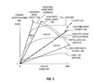
- FIG. 3 shows the shift map stored in the memory device 122.
- the transmission controller 12 controls the variator 20, the sub-transmission mechanism 30 and the lock-up clutch 2a according to operating conditions of the vehicle (in this embodiment, vehicle speed VSP, primary rotation speed Npri, accelerator pedal opening APO) while referring to this shift map.
- an operating point of the transmission 4 is defined by the vehicle speed VSP and the primary rotation speed Npri.
- the inclination of a line connecting the operating point of the transmission 4 and a zero point at the lower left corner of the shift map corresponds to the speed ratio of the transmission 4 (overall speed ratio obtained by multiplying the speed ratio of the variator 20 by a speed ratio of the sub-transmission mechanism 30, hereinafter, referred to as a "through speed ratio").
- a shift line is set for each accelerator pedal opening APO similarly to a shift map of a conventional belt-type continuously variable transmission, and the transmission 4 is shifted in accordance with the shift line selected according to the accelerator pedal opening APO.
- the transmission 4 When being in the low-speed mode, the transmission 4 can be shifted between a low-speed mode lowest line obtained by setting the speed ratio of the variator 20 to the lowest speed ratio and a low-speed mode highest line obtained by setting the speed ratio of the variator 20 to the highest speed ratio (areas A and B in FIG. 3 ).
- the transmission 4 when being in the high-speed mode, can be shifted between a high-speed mode lowest line obtained by setting the speed ratio of the variator 20 to the lowest speed ratio and a high-speed mode highest line obtained by setting the speed ratio of the variator 20 to the highest speed ratio (areas B and C in FIG. 3 ).
- a 1-2 shift line for determining an upshift of the sub-transmission mechanism 30 from the first gear position to the second gear position is so set as to overlap the low-speed mode highest line. If a targeted operating point of the transmission 4 crosses the 1-2 shift line from the area B side to the area C side, the transmission controller 12 upshifts the sub-transmission mechanism 30 from the first gear position to the second gear position.
- the sub-transmission mechanism 30 is downshifted from the second gear position to the first gear position only in a situation where a large drive force is required. In this way, a shift frequency of the sub-transmission mechanism 30 is reduced and a reduction in drivability due to the repeated occurrence of a shift shock and a reduction in the durability of frictional engagement elements of the sub-transmission mechanism are suppressed.
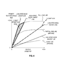
- the transmission controller 12 sets a 2-1 shift permitting area in the shift map as shown in FIG. 4 and downshifts the sub-transmission mechanism 30 from the second gear position to the first gear position, assuming that a large drive force is required, when the targeted operating point of the transmission 4 is in the 2-1 shift permitting area and a changing speed of the accelerator pedal opening APO is higher than a 2-1 shift permitting changing speed obtained by retrieving a map shown in FIG. 5 .
- the transmission controller 12 does not downshift the sub-transmission mechanism 30 when a torque change rate of the engine 1 is small even if the targeted operating point of the transmission 4 is in the 2-1 shift permitting area and the changing speed of the accelerator pedal opening APO is higher than the 2-1 shift permitting changing speed. This is to prevent the occurrence of a so-called draw-shock due to an inertia of the engine 1 when the sub-transmission mechanism 30 is downshifted from the second gear position to the first gear position.
- FIG. 6 shows the content of the shift control program stored in the memory device 122 of the transmission controller 12. With reference to this, the content of a shift control executed by the transmission controller 12 is described.
- the transmission controller 12 retrieves an operating point (targeted operating point of the transmission 4) corresponding to the current vehicle speed VSP and accelerator pedal opening APO from the shift map shown in FIG. 3 and sets the primary rotation speed corresponding to this as a destination primary rotation speed DsrREV.
- the destination primary rotation speed DsrREV is a primary rotation speed which should be achieved at the current vehicle speed VSP and accelerator pedal opening APO and a target value of the primary rotation speed.
- the transmission controller 12 computes a destination through speed ratio DRatio by dividing the destination primary rotation speed DsrREV by the vehicle speed VSP and a speed reduction ratio fRatio of the second gear train 5.
- the destination through speed ratio DRatio is a through speed ratio which should be achieved at the current vehicle speed VSP and accelerator pedal opening APO and a target value of the through speed ratio.
- the transmission controller 12 compares the destination through speed ratio DRatio and an actual through speed ratio Ratio and determines whether or not any shift is to be performed. The process proceeds to S14 if two values differ and the shift is determined to be performed while proceeding to S20 if the shift is determined not to be performed.
- the transmission controller 12 determines whether the shift to be performed next is an upshift or a downshift based on a relationship in magnitude between the destination through speed ratio DRatio and the actual through speed ratio Ratio.
- the transmission controller 12 executes an upshift control by an unillustrated process.
- the transmission controller 12 shifts the variator 20 to realize the destination through speed ratio DRatio and upshifts the sub-transmission mechanism 30 from the first gear position to the second gear position when the targeted operating point of the transmission 4 crosses the 1-2 shift line.
- the process proceeds to S 15 if the shift to be performed next is determined to be a downshift.
- the transmission controller 12 determines whether or not the gear position of the sub-transmission mechanism 30 is the second gear position and the targeted operating point of the transmission 4 is located in the 2-1 shift permitting area shown in FIG. 4 .
- the 2-1 shift permitting area is an area where the accelerator pedal opening APO is large, a large drive force is required and the sub-transmission mechanism 30 needs to be shifted to the first gear position to realize the through speed ratio of this area.
- the process proceeds to S16 if an affirmative determination is made while proceeding to S 19 if a negative determination is made.
- the transmission controller 12 retrieves the map of FIG. 5 , sets the 2-1 shift permitting changing speed corresponding to the accelerator pedal opening APO and the vehicle speed VSP and determines whether or not the changing speed of the accelerator pedal opening APO is higher than the 2-1 shift permitting changing speed.
- the 2-1 shift permitting changing speed is a threshold value for determining a situation where a large drive force is required. The process proceeds to S17 if an affirmative determination is made while proceeding to S 19 if a negative determination is made.
- the transmission controller 12 determines whether or not a torque change rate of the engine 1 is larger than a 2-1 shift permitting change rate (predetermined low change rate).
- the torque change rate of the engine 1 can be obtained by retrieving values corresponding to the accelerator pedal opening APO and the engine rotation speed Ne from a predetermined engine torque map and computing a change rate thereof.
- the 2-1 shift permitting change rate is set at a lower limit value of the torque change rate at which a phenomenon in which a torque decreases due to an inertia does not occur when the sub-transmission mechanism 30 is downshifted from the second gear position to the first gear position, i.e. at a lower limit value of the torque change rate at which a draw-shock does not occur.
- the process proceeds to S18 if an affirmative determination is made while proceeding to S19 if a negative determination is made.
- the transmission controller 12 downshifts the sub-transmission mechanism 30 from the second gear position to the first gear position. Further, the transmission controller 12 shifts the variator 20 so that the destination through speed ratio DRatio is realized.
- the transmission controller 12 shifts neither the variator 20 nor the sub-transmission mechanism 30.
- the sub-transmission mechanism 30 is normally downshifted (S18) if the targeted operating point of the transmission 4 is in the 2-1 shift permitting area and the changing speed of the accelerator pedal opening APO is higher than the 2-1 shift permitting changing speed, but the sub-transmission mechanism 30 is not downshifted and only the variator 20 is shifted (S 19) if the torque change rate of the engine 1 is smaller than the 2-1 shift permitting change rate.
- the targeted operating point of the transmission 4 enters the 2-1 shift permitting area and the accelerator pedal is quickly depressed when a change of the torque of the engine 1 with respect to the accelerator pedal opening APO is small (e.g. accelerator is nearly fully open), the sub-transmission mechanism 30 is not downshifted since a negative determination is made even if an affirmative determination is made in S 15, S16.
- the occurrence of a draw-shock caused by downshifting the sub-transmission mechanism 30 when the torque change rate of the engine 1 is small can be suppressed by restricting the downshift of the sub-transmission mechanism 30 when the torque change rate is small.
- the 2-1 shift permitting area is set to be an area enclosed by the low-speed mode lowest line, the high-speed mode lowest line, the full load line and the coast line, this is an example.
- the 2-1 shift permitting area can be set to be an area different from this.
- the power source is the engine 1 in the above embodiment, it may be a combination of the engine 1 and a motor or solely a motor.
Landscapes
- Engineering & Computer Science (AREA)
- General Engineering & Computer Science (AREA)
- Mechanical Engineering (AREA)
- Control Of Transmission Device (AREA)
Abstract
Description
- The present invention relates to a control of a continuously variable transmission with a sub-transmission mechanism.
-
JP2010-230117A - Since a shift frequency of the sub-transmission mechanism decreases according to this technology, a reduction in drivability due to the repeated occurrence of a shift shock and a reduction in the durability of frictional engagement elements of the sub-transmission mechanism can be suppressed.
- However, in the above technology, if an accelerator pedal is depressed at a speed higher than the predetermined speed after being depressed at a speed below the above predetermined speed until the accelerator pedal opening becomes larger than the above predetermined opening, there has been a possibility of the occurrence of a shift shock when the sub-transmission mechanism is downshifted.
- This is for the following reason. In a region where the accelerator pedal opening is larger than the above predetermined opening, an engine torque changes to a small degree or hardly in some cases even if the accelerator pedal is further depressed since an engine torque approaches a maximum value. If the downshift of the sub-transmission mechanism is started in this case, a phenomenon in which the torque decreases due to an inertia of an engine occurs when a rotation speed of the engine is increased to a rotation speed after the shift and a so-called draw-shock (shock in a deceleration direction to lose a drive force) occurs.
- The present invention aims to suppress a draw-shock in downshifting a sub-transmission mechanism in a continuously variable transmission with the sub-transmission mechanism.
- One aspect of the present invention provides a continuously variable transmission with a variator capable of continuously changing a speed ratio and a stepped sub-transmission mechanism for shifting and outputting output rotation of a power source, and a control method corresponding to this. The continuously variable transmission includes a downshift determining unit for determining whether or not to downshift the sub-transmission mechanism based on an opening and an opening speed of an accelerator pedal, which is an output adjusting device of the power source, and a torque change rate of the power source, and a shifting unit for downshifting the sub-transmission mechanism when a determination is made to downshift the sub-transmission mechanism.
- If the torque change rate of the power source is small, a phenomenon in which a torque decreases due to an inertia of the power source occurs in the case of downshifting the sub-transmission mechanism. Accordingly, if whether or not to downshift the sub-transmission mechanism is determined also considering the torque change rate of the power source as in the above aspect, the downshift of the sub-transmission mechanism can be prevented in a situation where a draw-shock occurs, whereby the occurrence of the draw-shock can be suppressed.
-
-
FIG. 1 is a schematic configuration diagram of a vehicle equipped with a continuously variable transmission according to an embodiment of the present invention, -
FIG. 2 is a diagram showing the internal configuration of a transmission controller, -
FIG. 3 is a shift map, -
FIG. 4 is a map for determining a 2-1 shift permitting area, -
FIG. 5 is a map for setting a 2-1 shift permitting changing speed, and -
FIG. 6 is a flow chart showing the content of a shift control program to be executed to the transmission controller. - Hereinafter, an embodiment of the present invention is described with reference to the accompanying drawings. It should be noted that, in the following description, a "speed ratio" of a certain transmission mechanism is a value obtained by dividing an input rotation speed of this transmission mechanism by an output rotation speed thereof. Further, a "lowest speed ratio" is a maximum speed ratio of this transmission mechanism and a "highest speed ratio" is a minimum speed ratio thereof.
-
FIG. 1 is a schematic configuration diagram of a vehicle equipped with a continuously variable transmission according to the embodiment of the present invention. This vehicle includes anengine 1 as a power source. Output rotation of theengine 1 is transmitted to drivewheels 7 via atorque converter 2, afirst gear train 3, atransmission 4, asecond gear train 5 and adifferential device 6. Thesecond gear train 5 includes aparking mechanism 8 for mechanically and unrotatably locking an output shaft of thetransmission 4 in a parked state. - The
torque converter 2 includes a lock-up clutch 2a. When the lock-up clutch 2a is engaged, there is no slip in thetorque converter 2 and transmission efficiency of thetorque converter 2 is improved. - Further, the vehicle is provided with an
oil pump 10 to be driven using a part of power of theengine 1, ahydraulic control circuit 11 for adjusting a hydraulic pressure from theoil pump 10 and supplying the adjusted hydraulic pressure to each component of thetransmission 4 and atransmission controller 12 for controlling thehydraulic control circuit 11. - The
transmission 4 is a continuously variable transmission including avariator 20 and asub-transmission mechanism 30 provided in series with thevariator 20. "To be provided in series" means that thevariator 20 and thesub-transmission mechanism 30 are provided in series in a power transmission path from theengine 1 to thedrive wheels 7. Thesub-transmission mechanism 30 may be directly connected to an output shaft of thevariator 20 as in this example or may be connected via another transmission or power transmission mechanism (e.g. gear train). Alternatively, thesub-transmission mechanism 30 may be connected to the preceding stage (input shaft side) of thevariator 20. - The
variator 20 is a continuously variable transmission mechanism including aprimary pulley 21, a secondary pulley 22 and a V-belt 23 mounted between thepulleys 21 and 22. Each of thepulleys 21, 22 includes a fixed conical plate, a movable conical plate arranged with a sheave surface faced toward the fixed conical plate and forming a V-groove between the fixed conical plate and the movable conical plate, andhydraulic cylinders hydraulic cylinders belt 23 and eachpulley 21, 22, whereby a speed ratio of thevariator 20 continuously changes. - The
sub-transmission mechanism 30 is a transmission mechanism with two forward speeds and one reverse speed and has a first gear position and a second gear position with a smaller speed ratio than in the first gear position as forward gear positions. In the following description, a case where thesub-transmission mechanism 30 is in the first gear position is expressed by that "thetransmission 4 is in a low-speed mode" and a case where thesub-transmission mechanism 30 is in the second gear position is expressed by that "thetransmission 4 is in a high-speed mode". - The
transmission controller 12 is, as shown inFIG. 2 , configured by aCPU 121, amemory device 122 composed of a RAM and a ROM, aninput interface 123, anoutput interface 124 and abus 125 which connects these components to each other. - To the
input interface 123 are input an output signal of an acceleratorpedal opening sensor 41 for detecting an accelerator pedal opening APO indicating an operated amount of an accelerator pedal, an output signal of arotation speed sensor 42 for detecting an input rotation speed of the transmission 4 (= rotation speed of theprimary pulley 21, hereinafter, referred to as a "primary rotation speed Npri"), an output signal of avehicle speed sensor 43 for detecting a vehicle speed VSP, an output signal of anoil temperature sensor 44 for detecting an oil temperature TMP of thetransmission 4, an output signal of aninhibitor switch 45 for detecting the position of a select lever, an output signal of arotation speed sensor 46 for detecting a rotation speed Ne of theengine 1 and the like. - A shift control program (
FIG. 6 ) of thetransmission 4 and various maps (FIGS. 3 to 5 ) used in this shift control program are stored in thememory device 122. TheCPU 121 reads and executes the shift control program stored in thememory device 122, performs various computations on various signals input via theinput interface 123 to generate a shift control signal, and outputs the generated shift control signal to thehydraulic control circuit 11 via theoutput interface 124. Various values used in the computations by theCPU 121 and computation results thereof are appropriately stored in thememory device 122. - The
hydraulic control circuit 11 is composed of a plurality of flow passages and a plurality of hydraulic control valves. In accordance with the shift control signal from thetransmission controller 12, thehydraulic control circuit 11 controls the plurality of hydraulic control valves to switch supply paths of the hydraulic pressure, prepares a necessary hydraulic pressure from a hydraulic pressure produced by theoil pump 10 and supplies this to each component of thetransmission 4. In this way, the speed ratio of thevariator 20 and the gear position of thesub-transmission mechanism 30 are changed and the lock-up clutch 2a is engaged and released. -
FIG. 3 shows the shift map stored in thememory device 122. Thetransmission controller 12 controls thevariator 20, thesub-transmission mechanism 30 and the lock-up clutch 2a according to operating conditions of the vehicle (in this embodiment, vehicle speed VSP, primary rotation speed Npri, accelerator pedal opening APO) while referring to this shift map. - In this shift map, an operating point of the
transmission 4 is defined by the vehicle speed VSP and the primary rotation speed Npri. The inclination of a line connecting the operating point of thetransmission 4 and a zero point at the lower left corner of the shift map corresponds to the speed ratio of the transmission 4 (overall speed ratio obtained by multiplying the speed ratio of thevariator 20 by a speed ratio of thesub-transmission mechanism 30, hereinafter, referred to as a "through speed ratio"). In the shift map, a shift line is set for each accelerator pedal opening APO similarly to a shift map of a conventional belt-type continuously variable transmission, and thetransmission 4 is shifted in accordance with the shift line selected according to the accelerator pedal opening APO. - When being in the low-speed mode, the
transmission 4 can be shifted between a low-speed mode lowest line obtained by setting the speed ratio of thevariator 20 to the lowest speed ratio and a low-speed mode highest line obtained by setting the speed ratio of thevariator 20 to the highest speed ratio (areas A and B inFIG. 3 ). On the other hand, when being in the high-speed mode, thetransmission 4 can be shifted between a high-speed mode lowest line obtained by setting the speed ratio of thevariator 20 to the lowest speed ratio and a high-speed mode highest line obtained by setting the speed ratio of thevariator 20 to the highest speed ratio (areas B and C inFIG. 3 ). - Further, on this map, a 1-2 shift line for determining an upshift of the
sub-transmission mechanism 30 from the first gear position to the second gear position is so set as to overlap the low-speed mode highest line. If a targeted operating point of thetransmission 4 crosses the 1-2 shift line from the area B side to the area C side, thetransmission controller 12 upshifts thesub-transmission mechanism 30 from the first gear position to the second gear position. - The
sub-transmission mechanism 30 is downshifted from the second gear position to the first gear position only in a situation where a large drive force is required. In this way, a shift frequency of thesub-transmission mechanism 30 is reduced and a reduction in drivability due to the repeated occurrence of a shift shock and a reduction in the durability of frictional engagement elements of the sub-transmission mechanism are suppressed. - Specifically, the
transmission controller 12 sets a 2-1 shift permitting area in the shift map as shown inFIG. 4 and downshifts thesub-transmission mechanism 30 from the second gear position to the first gear position, assuming that a large drive force is required, when the targeted operating point of thetransmission 4 is in the 2-1 shift permitting area and a changing speed of the accelerator pedal opening APO is higher than a 2-1 shift permitting changing speed obtained by retrieving a map shown inFIG. 5 . - However, the
transmission controller 12 does not downshift thesub-transmission mechanism 30 when a torque change rate of theengine 1 is small even if the targeted operating point of thetransmission 4 is in the 2-1 shift permitting area and the changing speed of the accelerator pedal opening APO is higher than the 2-1 shift permitting changing speed. This is to prevent the occurrence of a so-called draw-shock due to an inertia of theengine 1 when thesub-transmission mechanism 30 is downshifted from the second gear position to the first gear position. -
FIG. 6 shows the content of the shift control program stored in thememory device 122 of thetransmission controller 12. With reference to this, the content of a shift control executed by thetransmission controller 12 is described. - In S11, the
transmission controller 12 retrieves an operating point (targeted operating point of the transmission 4) corresponding to the current vehicle speed VSP and accelerator pedal opening APO from the shift map shown inFIG. 3 and sets the primary rotation speed corresponding to this as a destination primary rotation speed DsrREV. The destination primary rotation speed DsrREV is a primary rotation speed which should be achieved at the current vehicle speed VSP and accelerator pedal opening APO and a target value of the primary rotation speed. - In S12, the
transmission controller 12 computes a destination through speed ratio DRatio by dividing the destination primary rotation speed DsrREV by the vehicle speed VSP and a speed reduction ratio fRatio of thesecond gear train 5. The destination through speed ratio DRatio is a through speed ratio which should be achieved at the current vehicle speed VSP and accelerator pedal opening APO and a target value of the through speed ratio. - In S13, the
transmission controller 12 compares the destination through speed ratio DRatio and an actual through speed ratio Ratio and determines whether or not any shift is to be performed. The process proceeds to S14 if two values differ and the shift is determined to be performed while proceeding to S20 if the shift is determined not to be performed. - In S14, the
transmission controller 12 determines whether the shift to be performed next is an upshift or a downshift based on a relationship in magnitude between the destination through speed ratio DRatio and the actual through speed ratio Ratio. - If the shift to be performed next is determined to an upshift, the
transmission controller 12 executes an upshift control by an unillustrated process. In the upshift control, thetransmission controller 12 shifts thevariator 20 to realize the destination through speed ratio DRatio and upshifts thesub-transmission mechanism 30 from the first gear position to the second gear position when the targeted operating point of thetransmission 4 crosses the 1-2 shift line. - The process proceeds to
S 15 if the shift to be performed next is determined to be a downshift. - In S15, the
transmission controller 12 determines whether or not the gear position of thesub-transmission mechanism 30 is the second gear position and the targeted operating point of thetransmission 4 is located in the 2-1 shift permitting area shown inFIG. 4 . The 2-1 shift permitting area is an area where the accelerator pedal opening APO is large, a large drive force is required and thesub-transmission mechanism 30 needs to be shifted to the first gear position to realize the through speed ratio of this area. The process proceeds to S16 if an affirmative determination is made while proceeding toS 19 if a negative determination is made. - In S16, the
transmission controller 12 retrieves the map ofFIG. 5 , sets the 2-1 shift permitting changing speed corresponding to the accelerator pedal opening APO and the vehicle speed VSP and determines whether or not the changing speed of the accelerator pedal opening APO is higher than the 2-1 shift permitting changing speed. The 2-1 shift permitting changing speed is a threshold value for determining a situation where a large drive force is required. The process proceeds to S17 if an affirmative determination is made while proceeding toS 19 if a negative determination is made. - In S17, the
transmission controller 12 determines whether or not a torque change rate of theengine 1 is larger than a 2-1 shift permitting change rate (predetermined low change rate). The torque change rate of theengine 1 can be obtained by retrieving values corresponding to the accelerator pedal opening APO and the engine rotation speed Ne from a predetermined engine torque map and computing a change rate thereof. The 2-1 shift permitting change rate is set at a lower limit value of the torque change rate at which a phenomenon in which a torque decreases due to an inertia does not occur when thesub-transmission mechanism 30 is downshifted from the second gear position to the first gear position, i.e. at a lower limit value of the torque change rate at which a draw-shock does not occur. The process proceeds to S18 if an affirmative determination is made while proceeding to S19 if a negative determination is made. - In S18, the
transmission controller 12 downshifts thesub-transmission mechanism 30 from the second gear position to the first gear position. Further, thetransmission controller 12 shifts thevariator 20 so that the destination through speed ratio DRatio is realized. - In S19 proceeded to if a negative determination is made in S15 to S17, the
transmission controller 12 shifts only thevariator 20 so that the actual through speed ratio Ratio of thetransmission 4 approaches the destination through speed ratio DRatio. If the destination through speed ratio DRatio cannot be achieved only by shifting thevariator 20 since thesub-transmission mechanism 30 is in the second gear position, thevariator 20 is shifted to a lowest speed ratio. - Since the shift is not necessary if the process proceeds to S20, the
transmission controller 12 shifts neither thevariator 20 nor thesub-transmission mechanism 30. - Thus, according to the above shift control, the
sub-transmission mechanism 30 is normally downshifted (S18) if the targeted operating point of thetransmission 4 is in the 2-1 shift permitting area and the changing speed of the accelerator pedal opening APO is higher than the 2-1 shift permitting changing speed, but thesub-transmission mechanism 30 is not downshifted and only thevariator 20 is shifted (S 19) if the torque change rate of theengine 1 is smaller than the 2-1 shift permitting change rate. - For example, if the accelerator pedal is slowly depressed, the targeted operating point of the
transmission 4 enters the 2-1 shift permitting area and the accelerator pedal is quickly depressed when a change of the torque of theengine 1 with respect to the accelerator pedal opening APO is small (e.g. accelerator is nearly fully open), thesub-transmission mechanism 30 is not downshifted since a negative determination is made even if an affirmative determination is made inS 15, S16. - As just described, the occurrence of a draw-shock caused by downshifting the
sub-transmission mechanism 30 when the torque change rate of theengine 1 is small can be suppressed by restricting the downshift of thesub-transmission mechanism 30 when the torque change rate is small. - Although the embodiment of the present invention has been described above, the above embodiment is merely one application example of the present invention and not of the nature to limit the technical scope of the prevent invention to the specific configuration of the above embodiment.
- Further, although the 2-1 shift permitting area is set to be an area enclosed by the low-speed mode lowest line, the high-speed mode lowest line, the full load line and the coast line, this is an example. The 2-1 shift permitting area can be set to be an area different from this.
- Further, although the power source is the
engine 1 in the above embodiment, it may be a combination of theengine 1 and a motor or solely a motor. - The present application claims a priority of Japanese Patent Application No. 2012-213939 filed with the Japan Patent Office on September 27, 2012, all the contents of which are hereby incorporated by reference.
Claims (3)
- A continuously variable transmission with a variator capable of continuously changing a speed ratio and a stepped sub-transmission mechanism for shifting and outputting output ration of a power source, comprising:downshift determining means configured to determine whether or not to downshift the sub-transmission mechanism based on an opening and an opening speed of an accelerator pedal, which is an output adjusting device of the power source, and a torque change rate of the power source; andshifting means configured to downshift the sub-transmission mechanism when a determination is made to downshift the sub-transmission mechanism.
- The continuously variable transmission according to claim 1, wherein:the downshift determining means determines not to downshift the sub-transmission mechanism regardless of values of the opening and the opening speed of the accelerator pedal if the torque change rate of the power source is smaller than a predetermined low change rate.
- A control method for a continuously variable transmission with a variator capable of continuously changing a speed ratio and a stepped sub-transmission mechanism for shifting and outputting output ration of a power source, comprising:determining whether or not to downshift the sub-transmission mechanism based on an opening and an opening speed of an accelerator pedal, which is an output adjusting device of the power source, and a torque change rate of the power source; anddownshifting the sub-transmission mechanism when a determination is made to downshift the sub-transmission mechanism.
Applications Claiming Priority (2)
| Application Number | Priority Date | Filing Date | Title |
|---|---|---|---|
| JP2012213939 | 2012-09-27 | ||
| PCT/JP2013/073645 WO2014050453A1 (en) | 2012-09-27 | 2013-09-03 | Continuously variable transmission and control method thereof |
Publications (3)
| Publication Number | Publication Date |
|---|---|
| EP2902670A1 true EP2902670A1 (en) | 2015-08-05 |
| EP2902670A4 EP2902670A4 (en) | 2016-09-14 |
| EP2902670B1 EP2902670B1 (en) | 2017-07-19 |
Family
ID=50387862
Family Applications (1)
| Application Number | Title | Priority Date | Filing Date |
|---|---|---|---|
| EP13842656.4A Active EP2902670B1 (en) | 2012-09-27 | 2013-09-03 | Continuously variable transmission and control method thereof |
Country Status (6)
| Country | Link |
|---|---|
| US (1) | US9435434B2 (en) |
| EP (1) | EP2902670B1 (en) |
| JP (1) | JP5911587B2 (en) |
| KR (1) | KR101680989B1 (en) |
| CN (1) | CN104641155B (en) |
| WO (1) | WO2014050453A1 (en) |
Families Citing this family (6)
| Publication number | Priority date | Publication date | Assignee | Title |
|---|---|---|---|---|
| US10138819B2 (en) * | 2014-12-09 | 2018-11-27 | Kawasaki Jukogyo Kabushiki Kaisha | Vehicle, straddle-type vehicle, and method of driving throttle valve |
| WO2016125402A1 (en) * | 2015-02-02 | 2016-08-11 | ジヤトコ株式会社 | Automatic transmission control device |
| JP6500115B2 (en) * | 2015-09-10 | 2019-04-10 | ジヤトコ株式会社 | Control device for automatic transmission and control method for automatic transmission |
| US10385967B2 (en) * | 2015-11-09 | 2019-08-20 | GM Global Technology Operations LLC | Method and apparatus to control a continuously variable transmission |
| BR112018014696A2 (en) * | 2016-01-19 | 2018-12-11 | Nissan Motor Co., Ltd. | control device for a vehicle and method of controlling it |
| WO2019074009A1 (en) * | 2017-10-12 | 2019-04-18 | 三菱自動車工業株式会社 | Transmission control device |
Family Cites Families (14)
| Publication number | Priority date | Publication date | Assignee | Title |
|---|---|---|---|---|
| US4672863A (en) * | 1985-04-17 | 1987-06-16 | Toyota Jidosha Kabushiki Kaisha | Method and apparatus for controlling power transmission system in an automotive vehicle |
| JP3493904B2 (en) * | 1996-06-20 | 2004-02-03 | 日産自動車株式会社 | Transmission control device for continuously variable transmission |
| DE19950053A1 (en) * | 1999-10-16 | 2001-04-19 | Zahnradfabrik Friedrichshafen | Continuously variable adjustable vehicle gearbox has in multi-stage shifting gearbox, reversal of rotation direction by forward gears between input and output shaft |
| RU2005132989A (en) * | 2003-03-27 | 2006-05-27 | Торотрак (Дивелопмент) Лимитед (Gb) | METHOD FOR CONTINUOUS CONTROLLED TRANSMISSION MANAGEMENT |
| JP5330669B2 (en) | 2007-10-23 | 2013-10-30 | トヨタ自動車株式会社 | Control device for vehicle power transmission device |
| JP5251172B2 (en) * | 2008-03-06 | 2013-07-31 | 日産自動車株式会社 | Driving force control device for vehicle with continuously variable transmission |
| JP4923080B2 (en) | 2009-03-27 | 2012-04-25 | ジヤトコ株式会社 | Continuously variable transmission and control method thereof |
| JP4914467B2 (en) * | 2009-07-17 | 2012-04-11 | ジヤトコ株式会社 | Continuously variable transmission and control method thereof |
| JP5127884B2 (en) * | 2010-06-07 | 2013-01-23 | ジヤトコ株式会社 | Automatic transmission |
| JP5244875B2 (en) * | 2010-09-08 | 2013-07-24 | ジヤトコ株式会社 | Continuously variable transmission and control method thereof |
| JP5526005B2 (en) * | 2010-11-25 | 2014-06-18 | ジヤトコ株式会社 | Coast stop vehicle and coast stop vehicle control method |
| JP5708159B2 (en) | 2011-03-31 | 2015-04-30 | 大日本印刷株式会社 | LAMINATED SHEET AND METHOD FOR PRODUCING FOAM LAMINATED SHEET |
| CN103998829B (en) * | 2011-12-12 | 2016-06-08 | 加特可株式会社 | Continuously variable transmission and its control method |
| JP5267693B1 (en) * | 2012-02-17 | 2013-08-21 | トヨタ自動車株式会社 | vehicle |
-
2013
- 2013-09-03 US US14/430,665 patent/US9435434B2/en active Active
- 2013-09-03 WO PCT/JP2013/073645 patent/WO2014050453A1/en not_active Ceased
- 2013-09-03 EP EP13842656.4A patent/EP2902670B1/en active Active
- 2013-09-03 JP JP2014538320A patent/JP5911587B2/en active Active
- 2013-09-03 KR KR1020157005633A patent/KR101680989B1/en not_active Expired - Fee Related
- 2013-09-03 CN CN201380048381.4A patent/CN104641155B/en active Active
Also Published As
| Publication number | Publication date |
|---|---|
| EP2902670B1 (en) | 2017-07-19 |
| CN104641155A (en) | 2015-05-20 |
| KR101680989B1 (en) | 2016-11-29 |
| EP2902670A4 (en) | 2016-09-14 |
| KR20150041642A (en) | 2015-04-16 |
| US20150252895A1 (en) | 2015-09-10 |
| US9435434B2 (en) | 2016-09-06 |
| JP5911587B2 (en) | 2016-04-27 |
| JPWO2014050453A1 (en) | 2016-08-22 |
| CN104641155B (en) | 2016-09-21 |
| WO2014050453A1 (en) | 2014-04-03 |
Similar Documents
| Publication | Publication Date | Title |
|---|---|---|
| JP4923080B2 (en) | Continuously variable transmission and control method thereof | |
| KR101706898B1 (en) | Continuously variable transmission and method for controlling the same | |
| EP2275713B1 (en) | Shift control of continuously variable transmission | |
| KR101967570B1 (en) | Control device for continuously variable transmission of vehicle | |
| US8718883B2 (en) | Continuously variable transmission and power on/off determination method | |
| EP2436953B1 (en) | Coast stop vehicle and control method thereof | |
| EP2428710A2 (en) | Continuously variable transmission and control method therefore | |
| US9435434B2 (en) | Continuously variable transmission and control method therefor | |
| EP3176473B1 (en) | Continuously variable transmission and method for controlling the same | |
| KR20180101550A (en) | Sailing stop control method and control device for a vehicle | |
| KR101607040B1 (en) | Continuously variable transmission and method for controlling same | |
| US11236824B2 (en) | Continuously variable transmission control device and control method | |
| US9416873B2 (en) | Continuously variable transmission and control method therefor | |
| CN104487742A (en) | Automatic transmission for vehicle | |
| US11365805B2 (en) | Control device for vehicle and control method for vehicle | |
| JP2018105443A (en) | Controller and control method of continuously variable transmission with auxiliary transmission |
Legal Events
| Date | Code | Title | Description |
|---|---|---|---|
| PUAI | Public reference made under article 153(3) epc to a published international application that has entered the european phase |
Free format text: ORIGINAL CODE: 0009012 |
|
| 17P | Request for examination filed |
Effective date: 20150306 |
|
| AK | Designated contracting states |
Kind code of ref document: A1 Designated state(s): AL AT BE BG CH CY CZ DE DK EE ES FI FR GB GR HR HU IE IS IT LI LT LU LV MC MK MT NL NO PL PT RO RS SE SI SK SM TR |
|
| AX | Request for extension of the european patent |
Extension state: BA ME |
|
| DAX | Request for extension of the european patent (deleted) | ||
| RA4 | Supplementary search report drawn up and despatched (corrected) |
Effective date: 20160818 |
|
| RIC1 | Information provided on ipc code assigned before grant |
Ipc: F16H 61/66 20060101AFI20160811BHEP Ipc: F16H 59/18 20060101ALN20160811BHEP Ipc: F16H 59/14 20060101ALN20160811BHEP |
|
| REG | Reference to a national code |
Ref country code: DE Ref legal event code: R079 Ref document number: 602013023879 Country of ref document: DE Free format text: PREVIOUS MAIN CLASS: F16H0061160000 Ipc: F16H0061660000 |
|
| GRAP | Despatch of communication of intention to grant a patent |
Free format text: ORIGINAL CODE: EPIDOSNIGR1 |
|
| STAA | Information on the status of an ep patent application or granted ep patent |
Free format text: STATUS: GRANT OF PATENT IS INTENDED |
|
| RIC1 | Information provided on ipc code assigned before grant |
Ipc: F16H 59/18 20060101ALN20170124BHEP Ipc: F16H 61/66 20060101AFI20170124BHEP Ipc: F16H 59/14 20060101ALN20170124BHEP |
|
| INTG | Intention to grant announced |
Effective date: 20170227 |
|
| GRAS | Grant fee paid |
Free format text: ORIGINAL CODE: EPIDOSNIGR3 |
|
| GRAA | (expected) grant |
Free format text: ORIGINAL CODE: 0009210 |
|
| STAA | Information on the status of an ep patent application or granted ep patent |
Free format text: STATUS: THE PATENT HAS BEEN GRANTED |
|
| AK | Designated contracting states |
Kind code of ref document: B1 Designated state(s): AL AT BE BG CH CY CZ DE DK EE ES FI FR GB GR HR HU IE IS IT LI LT LU LV MC MK MT NL NO PL PT RO RS SE SI SK SM TR |
|
| RAP1 | Party data changed (applicant data changed or rights of an application transferred) |
Owner name: NISSAN MOTOR CO., LTD. Owner name: JATCO LTD |
|
| REG | Reference to a national code |
Ref country code: GB Ref legal event code: FG4D |
|
| REG | Reference to a national code |
Ref country code: CH Ref legal event code: EP |
|
| REG | Reference to a national code |
Ref country code: IE Ref legal event code: FG4D |
|
| REG | Reference to a national code |
Ref country code: AT Ref legal event code: REF Ref document number: 910713 Country of ref document: AT Kind code of ref document: T Effective date: 20170815 |
|
| REG | Reference to a national code |
Ref country code: DE Ref legal event code: R096 Ref document number: 602013023879 Country of ref document: DE |
|
| REG | Reference to a national code |
Ref country code: FR Ref legal event code: PLFP Year of fee payment: 5 |
|
| REG | Reference to a national code |
Ref country code: NL Ref legal event code: MP Effective date: 20170719 |
|
| REG | Reference to a national code |
Ref country code: LT Ref legal event code: MG4D |
|
| REG | Reference to a national code |
Ref country code: AT Ref legal event code: MK05 Ref document number: 910713 Country of ref document: AT Kind code of ref document: T Effective date: 20170719 |
|
| PG25 | Lapsed in a contracting state [announced via postgrant information from national office to epo] |
Ref country code: FI Free format text: LAPSE BECAUSE OF FAILURE TO SUBMIT A TRANSLATION OF THE DESCRIPTION OR TO PAY THE FEE WITHIN THE PRESCRIBED TIME-LIMIT Effective date: 20170719 Ref country code: NO Free format text: LAPSE BECAUSE OF FAILURE TO SUBMIT A TRANSLATION OF THE DESCRIPTION OR TO PAY THE FEE WITHIN THE PRESCRIBED TIME-LIMIT Effective date: 20171019 Ref country code: LT Free format text: LAPSE BECAUSE OF FAILURE TO SUBMIT A TRANSLATION OF THE DESCRIPTION OR TO PAY THE FEE WITHIN THE PRESCRIBED TIME-LIMIT Effective date: 20170719 Ref country code: SE Free format text: LAPSE BECAUSE OF FAILURE TO SUBMIT A TRANSLATION OF THE DESCRIPTION OR TO PAY THE FEE WITHIN THE PRESCRIBED TIME-LIMIT Effective date: 20170719 Ref country code: AT Free format text: LAPSE BECAUSE OF FAILURE TO SUBMIT A TRANSLATION OF THE DESCRIPTION OR TO PAY THE FEE WITHIN THE PRESCRIBED TIME-LIMIT Effective date: 20170719 Ref country code: NL Free format text: LAPSE BECAUSE OF FAILURE TO SUBMIT A TRANSLATION OF THE DESCRIPTION OR TO PAY THE FEE WITHIN THE PRESCRIBED TIME-LIMIT Effective date: 20170719 Ref country code: HR Free format text: LAPSE BECAUSE OF FAILURE TO SUBMIT A TRANSLATION OF THE DESCRIPTION OR TO PAY THE FEE WITHIN THE PRESCRIBED TIME-LIMIT Effective date: 20170719 |
|
| PG25 | Lapsed in a contracting state [announced via postgrant information from national office to epo] |
Ref country code: ES Free format text: LAPSE BECAUSE OF FAILURE TO SUBMIT A TRANSLATION OF THE DESCRIPTION OR TO PAY THE FEE WITHIN THE PRESCRIBED TIME-LIMIT Effective date: 20170719 Ref country code: RS Free format text: LAPSE BECAUSE OF FAILURE TO SUBMIT A TRANSLATION OF THE DESCRIPTION OR TO PAY THE FEE WITHIN THE PRESCRIBED TIME-LIMIT Effective date: 20170719 Ref country code: IS Free format text: LAPSE BECAUSE OF FAILURE TO SUBMIT A TRANSLATION OF THE DESCRIPTION OR TO PAY THE FEE WITHIN THE PRESCRIBED TIME-LIMIT Effective date: 20171119 Ref country code: PL Free format text: LAPSE BECAUSE OF FAILURE TO SUBMIT A TRANSLATION OF THE DESCRIPTION OR TO PAY THE FEE WITHIN THE PRESCRIBED TIME-LIMIT Effective date: 20170719 Ref country code: LV Free format text: LAPSE BECAUSE OF FAILURE TO SUBMIT A TRANSLATION OF THE DESCRIPTION OR TO PAY THE FEE WITHIN THE PRESCRIBED TIME-LIMIT Effective date: 20170719 Ref country code: GR Free format text: LAPSE BECAUSE OF FAILURE TO SUBMIT A TRANSLATION OF THE DESCRIPTION OR TO PAY THE FEE WITHIN THE PRESCRIBED TIME-LIMIT Effective date: 20171020 Ref country code: BG Free format text: LAPSE BECAUSE OF FAILURE TO SUBMIT A TRANSLATION OF THE DESCRIPTION OR TO PAY THE FEE WITHIN THE PRESCRIBED TIME-LIMIT Effective date: 20171019 |
|
| REG | Reference to a national code |
Ref country code: DE Ref legal event code: R097 Ref document number: 602013023879 Country of ref document: DE |
|
| PG25 | Lapsed in a contracting state [announced via postgrant information from national office to epo] |
Ref country code: DK Free format text: LAPSE BECAUSE OF FAILURE TO SUBMIT A TRANSLATION OF THE DESCRIPTION OR TO PAY THE FEE WITHIN THE PRESCRIBED TIME-LIMIT Effective date: 20170719 Ref country code: RO Free format text: LAPSE BECAUSE OF FAILURE TO SUBMIT A TRANSLATION OF THE DESCRIPTION OR TO PAY THE FEE WITHIN THE PRESCRIBED TIME-LIMIT Effective date: 20170719 Ref country code: CZ Free format text: LAPSE BECAUSE OF FAILURE TO SUBMIT A TRANSLATION OF THE DESCRIPTION OR TO PAY THE FEE WITHIN THE PRESCRIBED TIME-LIMIT Effective date: 20170719 |
|
| REG | Reference to a national code |
Ref country code: CH Ref legal event code: PL |
|
| PLBE | No opposition filed within time limit |
Free format text: ORIGINAL CODE: 0009261 |
|
| STAA | Information on the status of an ep patent application or granted ep patent |
Free format text: STATUS: NO OPPOSITION FILED WITHIN TIME LIMIT |
|
| PG25 | Lapsed in a contracting state [announced via postgrant information from national office to epo] |
Ref country code: EE Free format text: LAPSE BECAUSE OF FAILURE TO SUBMIT A TRANSLATION OF THE DESCRIPTION OR TO PAY THE FEE WITHIN THE PRESCRIBED TIME-LIMIT Effective date: 20170719 Ref country code: MC Free format text: LAPSE BECAUSE OF FAILURE TO SUBMIT A TRANSLATION OF THE DESCRIPTION OR TO PAY THE FEE WITHIN THE PRESCRIBED TIME-LIMIT Effective date: 20170719 Ref country code: SK Free format text: LAPSE BECAUSE OF FAILURE TO SUBMIT A TRANSLATION OF THE DESCRIPTION OR TO PAY THE FEE WITHIN THE PRESCRIBED TIME-LIMIT Effective date: 20170719 Ref country code: IT Free format text: LAPSE BECAUSE OF FAILURE TO SUBMIT A TRANSLATION OF THE DESCRIPTION OR TO PAY THE FEE WITHIN THE PRESCRIBED TIME-LIMIT Effective date: 20170719 Ref country code: SM Free format text: LAPSE BECAUSE OF FAILURE TO SUBMIT A TRANSLATION OF THE DESCRIPTION OR TO PAY THE FEE WITHIN THE PRESCRIBED TIME-LIMIT Effective date: 20170719 |
|
| 26N | No opposition filed |
Effective date: 20180420 |
|
| REG | Reference to a national code |
Ref country code: IE Ref legal event code: MM4A |
|
| REG | Reference to a national code |
Ref country code: BE Ref legal event code: MM Effective date: 20170930 |
|
| PG25 | Lapsed in a contracting state [announced via postgrant information from national office to epo] |
Ref country code: LU Free format text: LAPSE BECAUSE OF NON-PAYMENT OF DUE FEES Effective date: 20170903 |
|
| PG25 | Lapsed in a contracting state [announced via postgrant information from national office to epo] |
Ref country code: CH Free format text: LAPSE BECAUSE OF NON-PAYMENT OF DUE FEES Effective date: 20170930 Ref country code: LI Free format text: LAPSE BECAUSE OF NON-PAYMENT OF DUE FEES Effective date: 20170930 Ref country code: IE Free format text: LAPSE BECAUSE OF NON-PAYMENT OF DUE FEES Effective date: 20170903 |
|
| PG25 | Lapsed in a contracting state [announced via postgrant information from national office to epo] |
Ref country code: SI Free format text: LAPSE BECAUSE OF FAILURE TO SUBMIT A TRANSLATION OF THE DESCRIPTION OR TO PAY THE FEE WITHIN THE PRESCRIBED TIME-LIMIT Effective date: 20170719 Ref country code: BE Free format text: LAPSE BECAUSE OF NON-PAYMENT OF DUE FEES Effective date: 20170930 |
|
| REG | Reference to a national code |
Ref country code: FR Ref legal event code: PLFP Year of fee payment: 6 |
|
| PG25 | Lapsed in a contracting state [announced via postgrant information from national office to epo] |
Ref country code: MT Free format text: LAPSE BECAUSE OF NON-PAYMENT OF DUE FEES Effective date: 20170903 |
|
| PGFP | Annual fee paid to national office [announced via postgrant information from national office to epo] |
Ref country code: FR Payment date: 20180921 Year of fee payment: 6 |
|
| PGFP | Annual fee paid to national office [announced via postgrant information from national office to epo] |
Ref country code: DE Payment date: 20180928 Year of fee payment: 6 |
|
| PG25 | Lapsed in a contracting state [announced via postgrant information from national office to epo] |
Ref country code: HU Free format text: LAPSE BECAUSE OF FAILURE TO SUBMIT A TRANSLATION OF THE DESCRIPTION OR TO PAY THE FEE WITHIN THE PRESCRIBED TIME-LIMIT; INVALID AB INITIO Effective date: 20130903 |
|
| PG25 | Lapsed in a contracting state [announced via postgrant information from national office to epo] |
Ref country code: CY Free format text: LAPSE BECAUSE OF FAILURE TO SUBMIT A TRANSLATION OF THE DESCRIPTION OR TO PAY THE FEE WITHIN THE PRESCRIBED TIME-LIMIT Effective date: 20170719 |
|
| PG25 | Lapsed in a contracting state [announced via postgrant information from national office to epo] |
Ref country code: MK Free format text: LAPSE BECAUSE OF FAILURE TO SUBMIT A TRANSLATION OF THE DESCRIPTION OR TO PAY THE FEE WITHIN THE PRESCRIBED TIME-LIMIT Effective date: 20170719 |
|
| PG25 | Lapsed in a contracting state [announced via postgrant information from national office to epo] |
Ref country code: TR Free format text: LAPSE BECAUSE OF FAILURE TO SUBMIT A TRANSLATION OF THE DESCRIPTION OR TO PAY THE FEE WITHIN THE PRESCRIBED TIME-LIMIT Effective date: 20170719 |
|
| REG | Reference to a national code |
Ref country code: DE Ref legal event code: R119 Ref document number: 602013023879 Country of ref document: DE |
|
| PG25 | Lapsed in a contracting state [announced via postgrant information from national office to epo] |
Ref country code: PT Free format text: LAPSE BECAUSE OF FAILURE TO SUBMIT A TRANSLATION OF THE DESCRIPTION OR TO PAY THE FEE WITHIN THE PRESCRIBED TIME-LIMIT Effective date: 20170719 |
|
| PG25 | Lapsed in a contracting state [announced via postgrant information from national office to epo] |
Ref country code: DE Free format text: LAPSE BECAUSE OF NON-PAYMENT OF DUE FEES Effective date: 20200401 Ref country code: AL Free format text: LAPSE BECAUSE OF FAILURE TO SUBMIT A TRANSLATION OF THE DESCRIPTION OR TO PAY THE FEE WITHIN THE PRESCRIBED TIME-LIMIT Effective date: 20170719 |
|
| PG25 | Lapsed in a contracting state [announced via postgrant information from national office to epo] |
Ref country code: FR Free format text: LAPSE BECAUSE OF NON-PAYMENT OF DUE FEES Effective date: 20190930 |
|
| PGFP | Annual fee paid to national office [announced via postgrant information from national office to epo] |
Ref country code: GB Payment date: 20250820 Year of fee payment: 13 |