EP2902627A1 - Compressor - Google Patents
Compressor Download PDFInfo
- Publication number
- EP2902627A1 EP2902627A1 EP13841246.5A EP13841246A EP2902627A1 EP 2902627 A1 EP2902627 A1 EP 2902627A1 EP 13841246 A EP13841246 A EP 13841246A EP 2902627 A1 EP2902627 A1 EP 2902627A1
- Authority
- EP
- European Patent Office
- Prior art keywords
- compressor
- lid part
- oxygen
- noise
- adsorption cylinder
- Prior art date
- Legal status (The legal status is an assumption and is not a legal conclusion. Google has not performed a legal analysis and makes no representation as to the accuracy of the status listed.)
- Granted
Links
Images

Classifications
-
- F—MECHANICAL ENGINEERING; LIGHTING; HEATING; WEAPONS; BLASTING
- F04—POSITIVE - DISPLACEMENT MACHINES FOR LIQUIDS; PUMPS FOR LIQUIDS OR ELASTIC FLUIDS
- F04B—POSITIVE-DISPLACEMENT MACHINES FOR LIQUIDS; PUMPS
- F04B39/00—Component parts, details, or accessories, of pumps or pumping systems specially adapted for elastic fluids, not otherwise provided for in, or of interest apart from, groups F04B25/00 - F04B37/00
- F04B39/0027—Pulsation and noise damping means
- F04B39/0055—Pulsation and noise damping means with a special shape of fluid passage, e.g. bends, throttles, diameter changes, pipes
- F04B39/0061—Pulsation and noise damping means with a special shape of fluid passage, e.g. bends, throttles, diameter changes, pipes using muffler volumes
-
- A—HUMAN NECESSITIES
- A61—MEDICAL OR VETERINARY SCIENCE; HYGIENE
- A61M—DEVICES FOR INTRODUCING MEDIA INTO, OR ONTO, THE BODY; DEVICES FOR TRANSDUCING BODY MEDIA OR FOR TAKING MEDIA FROM THE BODY; DEVICES FOR PRODUCING OR ENDING SLEEP OR STUPOR
- A61M16/00—Devices for influencing the respiratory system of patients by gas treatment, e.g. ventilators; Tracheal tubes
- A61M16/0057—Pumps therefor
- A61M16/0063—Compressors
-
- A—HUMAN NECESSITIES
- A61—MEDICAL OR VETERINARY SCIENCE; HYGIENE
- A61M—DEVICES FOR INTRODUCING MEDIA INTO, OR ONTO, THE BODY; DEVICES FOR TRANSDUCING BODY MEDIA OR FOR TAKING MEDIA FROM THE BODY; DEVICES FOR PRODUCING OR ENDING SLEEP OR STUPOR
- A61M16/00—Devices for influencing the respiratory system of patients by gas treatment, e.g. ventilators; Tracheal tubes
- A61M16/10—Preparation of respiratory gases or vapours
- A61M16/1005—Preparation of respiratory gases or vapours with O2 features or with parameter measurement
- A61M16/101—Preparation of respiratory gases or vapours with O2 features or with parameter measurement using an oxygen concentrator
-
- F—MECHANICAL ENGINEERING; LIGHTING; HEATING; WEAPONS; BLASTING
- F04—POSITIVE - DISPLACEMENT MACHINES FOR LIQUIDS; PUMPS FOR LIQUIDS OR ELASTIC FLUIDS
- F04B—POSITIVE-DISPLACEMENT MACHINES FOR LIQUIDS; PUMPS
- F04B35/00—Piston pumps specially adapted for elastic fluids and characterised by the driving means to their working members, or by combination with, or adaptation to, specific driving engines or motors, not otherwise provided for
- F04B35/01—Piston pumps specially adapted for elastic fluids and characterised by the driving means to their working members, or by combination with, or adaptation to, specific driving engines or motors, not otherwise provided for the means being mechanical
-
- F—MECHANICAL ENGINEERING; LIGHTING; HEATING; WEAPONS; BLASTING
- F04—POSITIVE - DISPLACEMENT MACHINES FOR LIQUIDS; PUMPS FOR LIQUIDS OR ELASTIC FLUIDS
- F04B—POSITIVE-DISPLACEMENT MACHINES FOR LIQUIDS; PUMPS
- F04B39/00—Component parts, details, or accessories, of pumps or pumping systems specially adapted for elastic fluids, not otherwise provided for in, or of interest apart from, groups F04B25/00 - F04B37/00
- F04B39/0027—Pulsation and noise damping means
- F04B39/0055—Pulsation and noise damping means with a special shape of fluid passage, e.g. bends, throttles, diameter changes, pipes
-
- F—MECHANICAL ENGINEERING; LIGHTING; HEATING; WEAPONS; BLASTING
- F04—POSITIVE - DISPLACEMENT MACHINES FOR LIQUIDS; PUMPS FOR LIQUIDS OR ELASTIC FLUIDS
- F04B—POSITIVE-DISPLACEMENT MACHINES FOR LIQUIDS; PUMPS
- F04B39/00—Component parts, details, or accessories, of pumps or pumping systems specially adapted for elastic fluids, not otherwise provided for in, or of interest apart from, groups F04B25/00 - F04B37/00
- F04B39/12—Casings; Cylinders; Cylinder heads; Fluid connections
- F04B39/121—Casings
-
- F—MECHANICAL ENGINEERING; LIGHTING; HEATING; WEAPONS; BLASTING
- F04—POSITIVE - DISPLACEMENT MACHINES FOR LIQUIDS; PUMPS FOR LIQUIDS OR ELASTIC FLUIDS
- F04B—POSITIVE-DISPLACEMENT MACHINES FOR LIQUIDS; PUMPS
- F04B39/00—Component parts, details, or accessories, of pumps or pumping systems specially adapted for elastic fluids, not otherwise provided for in, or of interest apart from, groups F04B25/00 - F04B37/00
- F04B39/12—Casings; Cylinders; Cylinder heads; Fluid connections
- F04B39/128—Crankcases
-
- F—MECHANICAL ENGINEERING; LIGHTING; HEATING; WEAPONS; BLASTING
- F04—POSITIVE - DISPLACEMENT MACHINES FOR LIQUIDS; PUMPS FOR LIQUIDS OR ELASTIC FLUIDS
- F04B—POSITIVE-DISPLACEMENT MACHINES FOR LIQUIDS; PUMPS
- F04B39/00—Component parts, details, or accessories, of pumps or pumping systems specially adapted for elastic fluids, not otherwise provided for in, or of interest apart from, groups F04B25/00 - F04B37/00
- F04B39/16—Filtration; Moisture separation
-
- F—MECHANICAL ENGINEERING; LIGHTING; HEATING; WEAPONS; BLASTING
- F04—POSITIVE - DISPLACEMENT MACHINES FOR LIQUIDS; PUMPS FOR LIQUIDS OR ELASTIC FLUIDS
- F04B—POSITIVE-DISPLACEMENT MACHINES FOR LIQUIDS; PUMPS
- F04B43/00—Machines, pumps, or pumping installations having flexible working members
- F04B43/02—Machines, pumps, or pumping installations having flexible working members having plate-like flexible members, e.g. diaphragms
- F04B43/06—Pumps having fluid drive
- F04B43/073—Pumps having fluid drive the actuating fluid being controlled by at least one valve
- F04B43/0736—Pumps having fluid drive the actuating fluid being controlled by at least one valve with two or more pumping chambers in parallel
-
- A—HUMAN NECESSITIES
- A61—MEDICAL OR VETERINARY SCIENCE; HYGIENE
- A61M—DEVICES FOR INTRODUCING MEDIA INTO, OR ONTO, THE BODY; DEVICES FOR TRANSDUCING BODY MEDIA OR FOR TAKING MEDIA FROM THE BODY; DEVICES FOR PRODUCING OR ENDING SLEEP OR STUPOR
- A61M16/00—Devices for influencing the respiratory system of patients by gas treatment, e.g. ventilators; Tracheal tubes
- A61M16/10—Preparation of respiratory gases or vapours
- A61M16/105—Filters
- A61M16/106—Filters in a path
- A61M16/107—Filters in a path in the inspiratory path
-
- A—HUMAN NECESSITIES
- A61—MEDICAL OR VETERINARY SCIENCE; HYGIENE
- A61M—DEVICES FOR INTRODUCING MEDIA INTO, OR ONTO, THE BODY; DEVICES FOR TRANSDUCING BODY MEDIA OR FOR TAKING MEDIA FROM THE BODY; DEVICES FOR PRODUCING OR ENDING SLEEP OR STUPOR
- A61M2205/00—General characteristics of the apparatus
- A61M2205/42—Reducing noise
Definitions
- the present invention relates to a muffling function and a dust-proof filtering function of a compressor, especially to a medical oxygen concentration device providing users such as patients having respiratory disease with oxygen-enriched air, and to a device used for realizing the reduction of the particularly problematic compressor noise during operation of the device.
- oxygen inhalation therapy makes the patient inhale oxygen gas or oxygen-enriched air.
- An oxygen concentration device, liquid oxygen, an oxygen gas cylinder, etc. are known as the supply source, among which the oxygen concentration device is mainly used for home oxygen therapy due to its convenience in using and easiness in maintenance.
- the oxygen concentration device concentrates oxygen present in the air at about 21% and supplies an oxygen-enriched gas.
- the oxygen concentration device includes a membrane-type oxygen concentration device utilizing a membrane which selectively permeates oxygen and a pressure-swing adsorption type oxygen concentration device utilizing an adsorbent which is capable of preferentially adsorb nitrogen or oxygen.
- the latter is mainly used because of the advantage that high-concentration oxygen of 90% or more can be obtained.
- the pressure-swing adsorption type oxygen concentration device can continuously generate high-concentration oxygen-enriched gas by alternately repeating a pressurization/adsorption step to obtain an unadsorbed oxygen-enriched gas, wherein nitrogen is adsorbed on an adsorbent in an adsorbent cylinder filled with molecular sieve zeolite such as 5A type, 13X type, Li-X type, etc.
- the adsorbent which preferentially adsorbs nitrogen over oxygen under a pressurized condition by supplying air compressed using a compressor, and a depressurization/desorption step in which the adsorbent is regenerated by reducing the pressure in the adsorbent cylinder to atmospheric pressure or lower and purging nitrogen adsorbed on the adsorbent.
- Such an oxygen concentration device is mostly intended to be placed relatively close to the patient and is used continuously throughout the day by the patient regardless of dining or bedtime. Therefore, a noise generated from the oxygen concentration device is directly heard by the patient or patient's family, etc. and may give unpleasant feeling to them. There is concern that the noise has a significant influence particularly during sleep and the like by preventing the patient or the family from sleeping and thus negatively affecting their mental health.
- Sources of the noise generated by a pressure-swing absorption type oxygen concentration device include a structure-borne sound from a compressor for pressure variation, a suction sound and an exhaust sound from the compressor, an operating noise from a motor for driving the compressor, a purge gas flow noise of an adsorbent cylinder, and an operating noise from a cooling fan for the interior of the device housing.
- noises originated from the compressor such as the structure-borne sound radiation by the compressor, suction sound and exhaust sound of the compressor account for a large proportion of the whole device.
- a sound muffler called a cavity type or an expansion-chamber type has been used to reduce gas flow sounds such as the suction sound of the compressor and the like in a conventional oxygen concentration device.
- the sound muffler also needs to be miniaturized to realize a strong market demand of downsizing and weight reduction of the oxygen concentration device.
- space saving is achieved by eliminating dead space by shaping the sound muffler into a cuboid and by integrating the sound muffler into an attachment part of the air filter.
- the expansion-chamber muffler described above has such a feature that, as the ratio of the spatial cross-sectional area increases, the attenuation rate of the emitted sound increases, and the length of the cavity is related to the frequency of the sound desired to be reduced. Therefore, the physical size of the cavity is determined by the frequency band and the attenuation rate of the noise desired to be reduced, which is one of the obstacles for downsizing and weight reduction of the body of a low-noise oxygen concentration device.
- Japanese Unexamined Patent Application Publication No. 2003-235982 discloses a technique in which downsizing is maintained while serving sound attenuation by bringing an expansion-chamber muffler and a resonance muffler together and placing each muffler into the dead space.
- a conventional sound muffler needs to be connected to an intake port of a compressor, which is a vibrating body, through a pipe. Therefore, it becomes necessary to secure a structure, a space, and the like to isolate vibration, and there also arises a problem of space saving.
- Recent oxygen concentration devices are required to satisfy improved noise reduction performance, and there is also a strong demand for downsizing and weight reduction for a portable application. In order to realize these, it is essential to improve performance of the sound muffler itself as well as to downsize the same. Under a circumstance where installation of an intake sound muffler is indispensable for reducing intake noise that is the largest noise source of the compressor, development of various sound mufflers is under way, but to separately install an intake sound muffler for noise reduction is a technical problem contradictory to downsizing of the oxygen concentration device.
- the present invention provides a technology to realize noise reduction of the compressor itself, instead of installing a sound muffler, to suppress the intake noise generated by the compressor mounted on the oxygen concentration device.
- the present inventors have found the following inventions related to a compressor as a method to solve such problems.
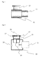
- Fig. 1 is a schematic diagram of external appearance of a reciprocating compressor
- Fig. 2 shows a schematic diagram of a configuration of a conventional compressor
- Fig. 3 shows a schematic diagram of a configuration of a compressor of an example of an embodiment of the present invention
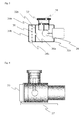
- Fig. 4 shows a schematic diagram of external appearance of a compressor
- Fig. 5 shows a schematic diagram of a configuration of an intake muffling function part
- Fig. 6 shows a schematic diagram of configuration of a compressor of an example of another embodiment of the present invention.
- a reciprocating compressor shown in Fig. 1 comprising one piston-cylinder is a device that converts a rotational motion of a motor 11 into a reciprocating motion of a piston in a cylinder 13 via a crank part housed in a casing 12, and introduces outside air into the cylinder, and supplies the same as compressed air.
- the compressor of the present invention is provided with a small chamber at an intake port side of a casing as shown in Fig. 3 .
- the small chamber is provided at an end of a cylindrical crank case 32a and is composed of a first lid part 39a provided with a conventional first intake port 36a, a second lid part 39b provided with a second intake port 36b which takes in outside air, and an extended cylindrical casing 32b and provided with a filter 30 inside.
- Such a filter 30 plays a role of a dust-proof filter and by installing, for example, a nonwoven filter in such a small chamber, there can be prevented intrusion of foreign matter into the compressor. Furthermore, this works favorably for downsizing of the device as a whole. For example, installation of a separate intake filter in the intake piping, as has been the case in the past, becomes unnecessary.
- a dust-proof filter cannot be expected to exhibit a muffling effect and, when a fine-meshed sound absorbing material such as one having a muffling effect is installed, there are caused demerits such as a increase in an intake pressure and the like.
- openings of the first intake port 36a and the second intake port 36b are not arranged in a straight position but are arranged so that air flow has an angle of 90°.
- the second intake port 36b is disposed on the side of the cylindrical part 32b.
- a compressor casing itself such that it possesses a small chamber comprising the first lid part and the second lid part shown in Fig. 3 .
- a structure such as shown in Fig. 5 , where a cap structure having a filter installed inside is fitted at the end of a casing.
- a material of the structure body may be made of a metal such as aluminum and the like, as well as one made of a heat-resistant resin such as ABS and the like.
- the compressor is configured by a first cap 51 having a first intake port 53 disposed at a center, a nonwoven filter 55, and a second cap 52 having a second intake port 54 provided on a side, which connects to an suction nozzle 57.
- the first cap 51 is provided with a lip to hold the filter 55 at a center and with a ring-shaped seal material 56.
- Raw material air taken in from the suction nozzle 57 can be introduced from the second cap 52 and, while maintaining a dust-free filter function by the filter 55, supplied into a compressor case from the first intake port 53 of the first cap 51.
- the first cap is provided with an O-ring on the outer surface and, by fitting the first cap at the end of the cylindrical compressor case, the cap can be sealed at the end of the compressor casing.
- the compressor of the present invention exhibits a noise level of 55 dBA
- the compressor of the present invention shown in Fig. 3 exhibits a noise level of 50 dBA, corresponding to a noise reduction effect of 10%
- the compressor shown in Fig. 4 equipped further with a 100 mm-long suction nozzle exhibits a noise level of 47 dBA, indicating a further noise reducing effect.
- the compressor of the present invention can be applied to a pressure swing adsorption-type oxygen concentration device.
- the oxygen concentration device comprises a compressor which supplies compressed air, an adsorption cylinder packed with an adsorbent which selectively adsorbs nitrogen rather than oxygen, and a flow path switching means which switches a sequence of an adsorption step, a desorption step, a pressure equalizing step, and the like.
- An oxygen-concentrated gas generated by separation from the compressed air in the adsorption cylinder is, after being stored in a product tank for a while, adjusted to prescribed pressure and a prescribed flow rate by a pressure control valve and a flow rate control valve, and thereafter supplied from an oxygen outlet port to a user by means of a nasal cannula.
- Raw material air brought into the device from outside contains about 21 % oxygen, about 77% nitrogen, 0.8% argon, and 1.2% other gases such as carbon dioxide and the like.
- Such oxygen concentration device enriches only oxygen, which is essential for respiration, and extracts it.
- the raw material air compressed by the compressor is supplied to an adsorption cylinder packed with an adsorbent formed of zeolite and the like, which selectively adsorbs nitrogen molecules rather than oxygen molecules, while switching the target adsorption cylinder sequentially by operating the supply and exhaust valves, and by selectively removing a nitrogen gas contained in the raw material air in the adsorption cylinder at a concentration of about 77%.
- an adsorbent there can be used molecular sieve zeolite such as Type 5A, Type 13X, Type Li-X, and the like.
- a reciprocating compressor such as a single head type shown in Fig. 4 provided with one piston-cylinder, or a double head type shown in Fig. 6 provided with two piston-cylinders.
- a compressor of the present invention possesses an intake muffling function and an intake filtering function by itself and, as a compressor that is light-weighted and downsized while maintaining reduced noise, can be used in medical devices such as a portable oxygen concentration device.
Landscapes
- Engineering & Computer Science (AREA)
- Health & Medical Sciences (AREA)
- General Engineering & Computer Science (AREA)
- Mechanical Engineering (AREA)
- Emergency Medicine (AREA)
- General Health & Medical Sciences (AREA)
- Veterinary Medicine (AREA)
- Hematology (AREA)
- Life Sciences & Earth Sciences (AREA)
- Animal Behavior & Ethology (AREA)
- Biomedical Technology (AREA)
- Public Health (AREA)
- Heart & Thoracic Surgery (AREA)
- Anesthesiology (AREA)
- Pulmonology (AREA)
- Compressor (AREA)
- Separation Of Gases By Adsorption (AREA)
- Compressors, Vaccum Pumps And Other Relevant Systems (AREA)
- Applications Or Details Of Rotary Compressors (AREA)
- Oxygen, Ozone, And Oxides In General (AREA)
Abstract
Description
- The present invention relates to a muffling function and a dust-proof filtering function of a compressor, especially to a medical oxygen concentration device providing users such as patients having respiratory disease with oxygen-enriched air, and to a device used for realizing the reduction of the particularly problematic compressor noise during operation of the device.
- In recent years, an increasing number of patients is suffering from respiratory diseases such as asthma, pulmonary emphysema, chronic bronchitis, etc. One of the most effective therapies for these diseases is oxygen inhalation therapy. Such oxygen inhalation therapy makes the patient inhale oxygen gas or oxygen-enriched air. An oxygen concentration device, liquid oxygen, an oxygen gas cylinder, etc. are known as the supply source, among which the oxygen concentration device is mainly used for home oxygen therapy due to its convenience in using and easiness in maintenance.
- The oxygen concentration device concentrates oxygen present in the air at about 21% and supplies an oxygen-enriched gas. The oxygen concentration device includes a membrane-type oxygen concentration device utilizing a membrane which selectively permeates oxygen and a pressure-swing adsorption type oxygen concentration device utilizing an adsorbent which is capable of preferentially adsorb nitrogen or oxygen. The latter is mainly used because of the advantage that high-concentration oxygen of 90% or more can be obtained.
- The pressure-swing adsorption type oxygen concentration device can continuously generate high-concentration oxygen-enriched gas by alternately repeating a pressurization/adsorption step to obtain an unadsorbed oxygen-enriched gas, wherein nitrogen is adsorbed on an adsorbent in an adsorbent cylinder filled with molecular sieve zeolite such as 5A type, 13X type, Li-X type, etc. as the adsorbent which preferentially adsorbs nitrogen over oxygen under a pressurized condition by supplying air compressed using a compressor, and a depressurization/desorption step in which the adsorbent is regenerated by reducing the pressure in the adsorbent cylinder to atmospheric pressure or lower and purging nitrogen adsorbed on the adsorbent.
- Such an oxygen concentration device is mostly intended to be placed relatively close to the patient and is used continuously throughout the day by the patient regardless of dining or bedtime. Therefore, a noise generated from the oxygen concentration device is directly heard by the patient or patient's family, etc. and may give unpleasant feeling to them. There is concern that the noise has a significant influence particularly during sleep and the like by preventing the patient or the family from sleeping and thus negatively affecting their mental health. Sources of the noise generated by a pressure-swing absorption type oxygen concentration device include a structure-borne sound from a compressor for pressure variation, a suction sound and an exhaust sound from the compressor, an operating noise from a motor for driving the compressor, a purge gas flow noise of an adsorbent cylinder, and an operating noise from a cooling fan for the interior of the device housing. Among them, noises originated from the compressor such as the structure-borne sound radiation by the compressor, suction sound and exhaust sound of the compressor account for a large proportion of the whole device.
- As described above, muffling the noise sources of the compressor is vital for the oxygen concentration device. A sound muffler called a cavity type or an expansion-chamber type has been used to reduce gas flow sounds such as the suction sound of the compressor and the like in a conventional oxygen concentration device. In addition to this, the sound muffler also needs to be miniaturized to realize a strong market demand of downsizing and weight reduction of the oxygen concentration device. For example, in a sound muffler described in Japanese Unexamined Patent Application Publication No.
H10-245203 - However, the expansion-chamber muffler described above has such a feature that, as the ratio of the spatial cross-sectional area increases, the attenuation rate of the emitted sound increases, and the length of the cavity is related to the frequency of the sound desired to be reduced. Therefore, the physical size of the cavity is determined by the frequency band and the attenuation rate of the noise desired to be reduced, which is one of the obstacles for downsizing and weight reduction of the body of a low-noise oxygen concentration device.
- In order to perform downsizing and weight reduction, while increasing the sound reducing effect of the sound muffler, Japanese Unexamined Patent Application Publication No.
2003-235982 - As a sound muffler for attenuating a noise in high frequency band and low frequency band based on different principles, such technique as described in Japanese Unexamined Patent Application Publication No.
2005-6731 -
- Japanese Unexamined Patent Application Publication No.
H10-245203 - Japanese Unexamined Patent Application Publication No.
2003-235982 - Japanese Unexamined Patent Application Publication No.
2005-6731 - Recent oxygen concentration devices are required to satisfy improved noise reduction performance, and there is also a strong demand for downsizing and weight reduction for a portable application. In order to realize these, it is essential to improve performance of the sound muffler itself as well as to downsize the same. Under a circumstance where installation of an intake sound muffler is indispensable for reducing intake noise that is the largest noise source of the compressor, development of various sound mufflers is under way, but to separately install an intake sound muffler for noise reduction is a technical problem contradictory to downsizing of the oxygen concentration device.
- The present invention provides a technology to realize noise reduction of the compressor itself, instead of installing a sound muffler, to suppress the intake noise generated by the compressor mounted on the oxygen concentration device.
- The present inventors have found the following inventions related to a compressor as a method to solve such problems.
- 1. A compressor comprising a small chamber provided at an end part of a casing thereof, the small chamber comprising:
- a first lid part provided with a small hole forming an intake port for raw material air for the compressor, the first lid part constituting a portion of the casing of the compressor;
- a cylindrical part and;
- a second lid part forming the small chamber together with the first lid part and the cylindrical part,
- wherein an suction nozzle for introducing air into the small chamber is provided.
- 2. The compressor according to paragraph 1, wherein a filter is installed in the small chamber to divide the chamber into a compressor intake port side and the suction nozzle side.
- 3. The compressor according to paragraph 1, wherein the suction nozzle has a length of 100 mm or more.
- 4. The compressor according to paragraph 1, wherein the compressor is a reciprocating compressor and the casing is the cylindrical crank case.
- 5. An oxygen concentration device comprising:
- an adsorption cylinder packed with an adsorbent which selectively adsorbs nitrogen rather than oxygen,
- a compressor which supplies compressed air to the adsorption cylinder, and
- a flow path switching valve which switches a flow path between the compressor, adsorption cylinder, and a discharge pipe in order to repeat at a fixed timing a sequence of an adsorption step where the adsorption cylinder is pressurized, and adsorbs nitrogen in the compressed air and generates un-adsorbed oxygen; and a desorption step where the adsorption cylinder is evacuated to regenerate the adsorbent,
- wherein the compressor according to paragraph 1 is provided as the compressor.
- According to the present invention, it is possible to provide a compressor that can maintain muffling performance, and can be downsized and light-weighted.
-
Fig. 1 is a schematic diagram of external appearance of a reciprocating compressor, andFig. 2 shows a schematic diagram of a configuration of a conventional compressor.Fig. 3 shows a schematic diagram of a configuration of a compressor of an example of an embodiment of the present invention,Fig. 4 shows a schematic diagram of external appearance of a compressor, andFig. 5 shows a schematic diagram of a configuration of an intake muffling function part.Fig. 6 shows a schematic diagram of configuration of a compressor of an example of another embodiment of the present invention. - The compressor of the present invention will be described in the following using drawings. In addition, the present invention is not restricted to such examples of embodiments.
- A reciprocating compressor shown in
Fig. 1 comprising one piston-cylinder is a device that converts a rotational motion of amotor 11 into a reciprocating motion of a piston in acylinder 13 via a crank part housed in acasing 12, and introduces outside air into the cylinder, and supplies the same as compressed air. - As shown by a cross-sectional schematic diagram of
Fig. 2 , outside air taken in from anintake port 26 provided on a crankcase 22 is transported as raw material air into acylinder 23 via anintake valve 27 provided on apiston 25, compressed by a vertical motion of thepiston 25, and supplied as compressed air from anexhaust valve 28 provided on an upper part of the cylinder. Even though most of noise generated by reciprocating motions of a crankpart 24 which converts a rotational motion of themotor 21 into a reciprocating motion of the piston, and thepiston 25 in the cylinder and, further by movements of intake and exhaust valves is confined in the case, a portion of the noise leaks outside from the intake port for introducing the raw material air, thus causing a problem of compressor noise. - The compressor of the present invention is provided with a small chamber at an intake port side of a casing as shown in
Fig. 3 . Specifically, the small chamber is provided at an end of a cylindrical crankcase 32a and is composed of afirst lid part 39a provided with a conventionalfirst intake port 36a, asecond lid part 39b provided with asecond intake port 36b which takes in outside air, and an extendedcylindrical casing 32b and provided with afilter 30 inside. - Such a
filter 30 plays a role of a dust-proof filter and by installing, for example, a nonwoven filter in such a small chamber, there can be prevented intrusion of foreign matter into the compressor. Furthermore, this works favorably for downsizing of the device as a whole. For example, installation of a separate intake filter in the intake piping, as has been the case in the past, becomes unnecessary. Such a dust-proof filter cannot be expected to exhibit a muffling effect and, when a fine-meshed sound absorbing material such as one having a muffling effect is installed, there are caused demerits such as a increase in an intake pressure and the like. - In order to enhance the muffling effect, openings of the
first intake port 36a and thesecond intake port 36b are not arranged in a straight position but are arranged so that air flow has an angle of 90°. Thus, when thefirst intake port 36a is disposed at a center of thefirst lib part 39a, thesecond intake port 36b is disposed on the side of thecylindrical part 32b. Furthermore, by making a diameter of the small chamber 5 times or more, more preferably 10 times or more of a diameter of each intake port, there is exhibited an expansion-chamber type muffling effect. - When outside air is taken in directly from the
second intake port 36b, the compressor noise cannot be suppressed sufficiently. As shown inFig. 4 , it is important to install ansuction nozzle 57 having a length of at least 100 mm. The longer the suction nozzle, the better the noise reduction effect is exhibited. However, when the nozzle is too long, an intake pressure increases, causing a decrease in an intake-air quantity. From the point of view of a balance between securing of a necessary quantity of intake-air and the noise reduction effect, it is preferable to use a nozzle length of 100 mm to 150 mm. - It is costly to fabricate a compressor casing itself such that it possesses a small chamber comprising the first lid part and the second lid part shown in
Fig. 3 . In the present invention, it is preferable to employ a structure such as shown inFig. 5 , where a cap structure having a filter installed inside is fitted at the end of a casing. A material of the structure body may be made of a metal such as aluminum and the like, as well as one made of a heat-resistant resin such as ABS and the like. - Specifically, as
Fig. 5 shows constituent members, the compressor is configured by afirst cap 51 having afirst intake port 53 disposed at a center, anonwoven filter 55, and asecond cap 52 having asecond intake port 54 provided on a side, which connects to ansuction nozzle 57. Thefirst cap 51 is provided with a lip to hold thefilter 55 at a center and with a ring-shapedseal material 56. Raw material air taken in from thesuction nozzle 57 can be introduced from thesecond cap 52 and, while maintaining a dust-free filter function by thefilter 55, supplied into a compressor case from thefirst intake port 53 of thefirst cap 51. - The first cap is provided with an O-ring on the outer surface and, by fitting the first cap at the end of the cylindrical compressor case, the cap can be sealed at the end of the compressor casing. Thus, there can be produced simply and economically the compressor of the present invention having a small chamber provided with a muffling function and a dust-proof function.
- In addition, even though the present invention has so far been described with a reciprocating compressor having one piston-cylinder as an example, the present invention can be applied along the same way of thinking to crank case parts of a reciprocating compressor provided with two piston-cylinders as described in
Fig. 6 . - When the noise reduction effects of the compressors of the present invention are compared, while the conventional reciprocating compressor shown in
Fig. 2 provided with one piston-cylinder exhibits a noise level of 55 dBA, the compressor of the present invention shown inFig. 3 exhibits a noise level of 50 dBA, corresponding to a noise reduction effect of 10%, and furthermore, the compressor shown inFig. 4 equipped further with a 100 mm-long suction nozzle exhibits a noise level of 47 dBA, indicating a further noise reducing effect. - The compressor of the present invention can be applied to a pressure swing adsorption-type oxygen concentration device. The oxygen concentration device comprises a compressor which supplies compressed air, an adsorption cylinder packed with an adsorbent which selectively adsorbs nitrogen rather than oxygen, and a flow path switching means which switches a sequence of an adsorption step, a desorption step, a pressure equalizing step, and the like. An oxygen-concentrated gas generated by separation from the compressed air in the adsorption cylinder is, after being stored in a product tank for a while, adjusted to prescribed pressure and a prescribed flow rate by a pressure control valve and a flow rate control valve, and thereafter supplied from an oxygen outlet port to a user by means of a nasal cannula.
- Raw material air brought into the device from outside contains about 21 % oxygen, about 77% nitrogen, 0.8% argon, and 1.2% other gases such as carbon dioxide and the like. Such oxygen concentration device enriches only oxygen, which is essential for respiration, and extracts it.
- To extract the oxygen-concentrated gas, the raw material air compressed by the compressor is supplied to an adsorption cylinder packed with an adsorbent formed of zeolite and the like, which selectively adsorbs nitrogen molecules rather than oxygen molecules, while switching the target adsorption cylinder sequentially by operating the supply and exhaust valves, and by selectively removing a nitrogen gas contained in the raw material air in the adsorption cylinder at a concentration of about 77%. As such an adsorbent, there can be used molecular sieve zeolite such as Type 5A, Type 13X, Type Li-X, and the like.
- As such a compressor, there is used a reciprocating compressor such as a single head type shown in
Fig. 4 provided with one piston-cylinder, or a double head type shown inFig. 6 provided with two piston-cylinders. By so doing, a downsized and low-noise oxygen concentration device can be constituted without separately installing an intake sound muffler. - A compressor of the present invention possesses an intake muffling function and an intake filtering function by itself and, as a compressor that is light-weighted and downsized while maintaining reduced noise, can be used in medical devices such as a portable oxygen concentration device.
Claims (5)
- A compressor comprising:a first lid part provided with a small hole which forms an intake port of the compressor, the lid part constituting a portion of a cylindrical casing of the compressor;a cylindrical part; anda second lid part which forms a small chamber together with the first lid part,wherein the second lid part is provided with a suction nozzle for sucking air into the small chamber.
- The compressor according to claim 1, wherein a filter is installed in the small chamber to divide the chamber into a compressor intake port side and the suction nozzle side.
- The compressor according to claim 1, wherein the suction nozzle has a length of 100 mm or more.
- The compressor according to claim 1, wherein the compressor is a reciprocating compressor and the casing is a cylindrical crank case.
- An oxygen concentration device comprising:an adsorption cylinder packed with an adsorbent which selectively adsorbs nitrogen rather than oxygen,a compressor which supplies compressed air to the adsorption cylinder, anda flow path switching valve which switches a flow path between the compressor, adsorption cylinder, and a discharge pipe in order to repeat at a fixed timing a sequence of an adsorption step where the adsorption cylinder is pressurized, and adsorbs nitrogen in the compressed air and generates un-adsorbed oxygen; and a desorption step where the adsorption cylinder is evacuated to regenerate the adsorbent,wherein the compressor is the compressor according to claim 1.
Applications Claiming Priority (2)
| Application Number | Priority Date | Filing Date | Title |
|---|---|---|---|
| JP2012212481 | 2012-09-26 | ||
| PCT/JP2013/076169 WO2014051016A1 (en) | 2012-09-26 | 2013-09-19 | Compressor |
Publications (3)
| Publication Number | Publication Date |
|---|---|
| EP2902627A1 true EP2902627A1 (en) | 2015-08-05 |
| EP2902627A4 EP2902627A4 (en) | 2015-12-16 |
| EP2902627B1 EP2902627B1 (en) | 2019-06-05 |
Family
ID=50388410
Family Applications (1)
| Application Number | Title | Priority Date | Filing Date |
|---|---|---|---|
| EP13841246.5A Active EP2902627B1 (en) | 2012-09-26 | 2013-09-19 | Compressor |
Country Status (11)
| Country | Link |
|---|---|
| US (1) | US10087919B2 (en) |
| EP (1) | EP2902627B1 (en) |
| JP (1) | JP6092886B2 (en) |
| KR (1) | KR102139839B1 (en) |
| CN (1) | CN104641113A (en) |
| BR (1) | BR112015006395A2 (en) |
| ES (1) | ES2733239T3 (en) |
| HK (2) | HK1211650A1 (en) |
| SG (1) | SG11201502356YA (en) |
| TW (1) | TW201425728A (en) |
| WO (1) | WO2014051016A1 (en) |
Families Citing this family (4)
| Publication number | Priority date | Publication date | Assignee | Title |
|---|---|---|---|---|
| CN107218200B (en) * | 2017-05-24 | 2019-01-01 | 安徽寅时压缩机制造有限公司 | A kind of split-compressor with roll-over type filtering plate |
| CN111522414B (en) * | 2020-04-27 | 2022-03-18 | 齐鲁工业大学 | Computer thing networking installing support |
| EP4112931A1 (en) * | 2021-06-30 | 2023-01-04 | KNORR-BREMSE Systeme für Nutzfahrzeuge GmbH | Noise reduction of a compressor |
| KR20260020283A (en) * | 2024-08-01 | 2026-02-11 | 주식회사 제우스 | Pump device for semiconductor cleaning |
Family Cites Families (33)
| Publication number | Priority date | Publication date | Assignee | Title |
|---|---|---|---|---|
| US4124091A (en) * | 1975-12-24 | 1978-11-07 | Toyota Jidosha Kogyo Kabushiki Kaisha | Silencer for an internal combustion engine |
| JPS59105979A (en) * | 1982-12-09 | 1984-06-19 | Toshiba Corp | Manufacture of muffler for compressor |
| JPS59174380U (en) * | 1983-05-07 | 1984-11-21 | 日立工機株式会社 | compressor |
| JPS63176677A (en) * | 1987-01-14 | 1988-07-20 | Sanyo Electric Co Ltd | Muffler for compressor |
| JPH0787884B2 (en) * | 1989-07-17 | 1995-09-27 | 富士通株式会社 | Air filter for pump |
| US5059221A (en) * | 1989-08-15 | 1991-10-22 | Siemens-Bendix Automotive Electronics Limited | Integrated air cleaner assembly |
| JPH06117375A (en) * | 1992-10-02 | 1994-04-26 | Matsushita Refrig Co Ltd | Sealed compressor for hfc-134a refrigerant and ester refrigerator oil |
| JP2976769B2 (en) * | 1993-09-24 | 1999-11-10 | 凸版印刷株式会社 | Vegetables freshness packaging method |
| BR9603046A (en) * | 1996-07-01 | 1997-05-20 | Westaflex Tubos Flexiveis Ltda | Shaped acoustic tubular device and internally attachable to the clean air tube of the vehicle engine intake manifold |
| JPH10245203A (en) | 1997-03-04 | 1998-09-14 | Teijin Ltd | Oxygen concentrator |
| KR100269951B1 (en) * | 1997-11-05 | 2000-10-16 | 배길성 | Sucking muffler of a compressor |
| US5996734A (en) * | 1998-03-11 | 1999-12-07 | Outboard Marine Corporation | Air intake silencer for a two-stroke engine |
| JP2000179458A (en) * | 1998-12-15 | 2000-06-27 | Sanden Corp | Reciprocating compressor |
| JP2000320458A (en) | 1999-05-12 | 2000-11-21 | Kofu Meidensha:Kk | Compression mechanism |
| US6524080B2 (en) * | 2000-04-11 | 2003-02-25 | R. K. Dewan & Co. | Hermetically sealed compressors |
| JP3677447B2 (en) * | 2000-11-27 | 2005-08-03 | 松下冷機株式会社 | Hermetic compressor |
| US7263995B2 (en) * | 2001-02-28 | 2007-09-04 | Hyperbaric Technology, Inc. | Hyperbaric oxygen therapy system controls |
| KR100414122B1 (en) | 2001-12-22 | 2004-01-07 | 엘지전자 주식회사 | Noise decrease case for compressor |
| JP2003235982A (en) | 2002-02-18 | 2003-08-26 | Teijin Ltd | Medical pressure fluctuation adsorption type oxygen concentrator |
| WO2003074113A1 (en) | 2002-03-05 | 2003-09-12 | Teijin Limited | Oxygen enricher |
| US6648612B2 (en) | 2002-03-25 | 2003-11-18 | I-Min Hsiao | Oil-free air compressor |
| JP2004261223A (en) | 2003-02-14 | 2004-09-24 | Teijin Ltd | Medical oxygen concentrator |
| JP2005006731A (en) | 2003-06-17 | 2005-01-13 | Teijin Ltd | Oxygen concentrator |
| CN100353072C (en) * | 2004-04-29 | 2007-12-05 | 李玉斌 | Rotary compressor of centralized air-breathing and exhaust |
| US20060045768A1 (en) * | 2004-08-24 | 2006-03-02 | Fei-Tyh Chuang | Oil-less air compressor |
| JPWO2006121139A1 (en) | 2005-05-06 | 2008-12-18 | 帝人ファーマ株式会社 | Silencer and oxygen concentrator equipped with the silencer |
| JP2007032339A (en) * | 2005-07-25 | 2007-02-08 | Mitsubishi Electric Corp | Engine intake system |
| EP1890037A1 (en) * | 2006-08-07 | 2008-02-20 | Dürr Dental GmbH & Co. KG | Compressor |
| US7383810B1 (en) * | 2007-02-22 | 2008-06-10 | Automotive Components Holdings, Llc | Air induction system having an integrated resonator |
| AU2010280388A1 (en) * | 2009-08-03 | 2012-03-29 | Koninklijke Philips Electronics N.V. | Low restriction resonator with adjustable frequency characteristics for use in compressor nebulizer systems |
| JP5495766B2 (en) * | 2009-12-18 | 2014-05-21 | 株式会社医器研 | Oxygen concentrator |
| CN101737296A (en) * | 2010-01-08 | 2010-06-16 | 浙江鸿友压缩机制造有限公司 | Low-noise structural oilless air compressor |
| US10436188B2 (en) * | 2014-04-30 | 2019-10-08 | Mat Industries, Llc | Compressor shroud having integral muffler and inertial filter |
-
2013
- 2013-09-19 BR BR112015006395A patent/BR112015006395A2/en not_active Application Discontinuation
- 2013-09-19 CN CN201380050423.8A patent/CN104641113A/en active Pending
- 2013-09-19 WO PCT/JP2013/076169 patent/WO2014051016A1/en not_active Ceased
- 2013-09-19 EP EP13841246.5A patent/EP2902627B1/en active Active
- 2013-09-19 SG SG11201502356YA patent/SG11201502356YA/en unknown
- 2013-09-19 KR KR1020157008381A patent/KR102139839B1/en active Active
- 2013-09-19 US US14/423,725 patent/US10087919B2/en active Active
- 2013-09-19 ES ES13841246T patent/ES2733239T3/en active Active
- 2013-09-19 HK HK15112492.1A patent/HK1211650A1/en unknown
- 2013-09-19 JP JP2014538608A patent/JP6092886B2/en active Active
- 2013-09-19 HK HK15107067.6A patent/HK1206410A1/en unknown
- 2013-09-25 TW TW102134550A patent/TW201425728A/en unknown
Also Published As
| Publication number | Publication date |
|---|---|
| EP2902627B1 (en) | 2019-06-05 |
| JP6092886B2 (en) | 2017-03-08 |
| JPWO2014051016A1 (en) | 2016-08-22 |
| US20150204318A1 (en) | 2015-07-23 |
| HK1206410A1 (en) | 2016-01-08 |
| HK1211650A1 (en) | 2016-05-27 |
| KR20150063406A (en) | 2015-06-09 |
| US10087919B2 (en) | 2018-10-02 |
| ES2733239T3 (en) | 2019-11-28 |
| BR112015006395A2 (en) | 2017-07-04 |
| SG11201502356YA (en) | 2015-05-28 |
| WO2014051016A1 (en) | 2014-04-03 |
| KR102139839B1 (en) | 2020-07-30 |
| TW201425728A (en) | 2014-07-01 |
| EP2902627A4 (en) | 2015-12-16 |
| CN104641113A (en) | 2015-05-20 |
Similar Documents
| Publication | Publication Date | Title |
|---|---|---|
| JPWO2006121139A1 (en) | Silencer and oxygen concentrator equipped with the silencer | |
| US10087919B2 (en) | Air compressor with improved noise reduction performance | |
| US10029064B2 (en) | Sound muffler and oxygen concentration device comprising the same | |
| JP2023521979A (en) | Methods and apparatus for providing concentrated therapeutic gas for respiratory disorders | |
| JP5275677B2 (en) | Oxygen concentrator | |
| JPH10245203A (en) | Oxygen concentrator | |
| JP2005006732A (en) | Oxygen concentrator | |
| JP2005066150A (en) | Oxygen concentrator | |
| JP2003235982A (en) | Medical pressure fluctuation adsorption type oxygen concentrator | |
| JP2005006731A (en) | Oxygen concentrator | |
| HK1204588B (en) | Sound damper and oxygen concentration device comprising same | |
| JP2005198804A (en) | Oxygen concentrator | |
| JP5242928B2 (en) | Oxygen concentrator | |
| JP2005143863A (en) | Oxygen enricher | |
| HK1117085A (en) | Silencer and oxygen concentration device using the same | |
| HK1117086A (en) | Silencer and oxygen concentration device using the same | |
| HK1200748B (en) | Sound damper and oxygen concentration device comprising same |
Legal Events
| Date | Code | Title | Description |
|---|---|---|---|
| PUAI | Public reference made under article 153(3) epc to a published international application that has entered the european phase |
Free format text: ORIGINAL CODE: 0009012 |
|
| 17P | Request for examination filed |
Effective date: 20150316 |
|
| AK | Designated contracting states |
Kind code of ref document: A1 Designated state(s): AL AT BE BG CH CY CZ DE DK EE ES FI FR GB GR HR HU IE IS IT LI LT LU LV MC MK MT NL NO PL PT RO RS SE SI SK SM TR |
|
| AX | Request for extension of the european patent |
Extension state: BA ME |
|
| RA4 | Supplementary search report drawn up and despatched (corrected) |
Effective date: 20151113 |
|
| RIC1 | Information provided on ipc code assigned before grant |
Ipc: A61M 16/10 20060101ALI20151109BHEP Ipc: F04B 39/16 20060101ALI20151109BHEP Ipc: F04B 39/00 20060101AFI20151109BHEP |
|
| DAX | Request for extension of the european patent (deleted) | ||
| REG | Reference to a national code |
Ref country code: HK Ref legal event code: DE Ref document number: 1211650 Country of ref document: HK |
|
| GRAP | Despatch of communication of intention to grant a patent |
Free format text: ORIGINAL CODE: EPIDOSNIGR1 |
|
| STAA | Information on the status of an ep patent application or granted ep patent |
Free format text: STATUS: GRANT OF PATENT IS INTENDED |
|
| INTG | Intention to grant announced |
Effective date: 20190128 |
|
| GRAS | Grant fee paid |
Free format text: ORIGINAL CODE: EPIDOSNIGR3 |
|
| GRAA | (expected) grant |
Free format text: ORIGINAL CODE: 0009210 |
|
| STAA | Information on the status of an ep patent application or granted ep patent |
Free format text: STATUS: THE PATENT HAS BEEN GRANTED |
|
| AK | Designated contracting states |
Kind code of ref document: B1 Designated state(s): AL AT BE BG CH CY CZ DE DK EE ES FI FR GB GR HR HU IE IS IT LI LT LU LV MC MK MT NL NO PL PT RO RS SE SI SK SM TR |
|
| REG | Reference to a national code |
Ref country code: GB Ref legal event code: FG4D |
|
| REG | Reference to a national code |
Ref country code: CH Ref legal event code: EP |
|
| REG | Reference to a national code |
Ref country code: AT Ref legal event code: REF Ref document number: 1140256 Country of ref document: AT Kind code of ref document: T Effective date: 20190615 |
|
| REG | Reference to a national code |
Ref country code: IE Ref legal event code: FG4D |
|
| REG | Reference to a national code |
Ref country code: DE Ref legal event code: R096 Ref document number: 602013056319 Country of ref document: DE |
|
| REG | Reference to a national code |
Ref country code: NL Ref legal event code: MP Effective date: 20190605 |
|
| REG | Reference to a national code |
Ref country code: LT Ref legal event code: MG4D |
|
| PG25 | Lapsed in a contracting state [announced via postgrant information from national office to epo] |
Ref country code: AL Free format text: LAPSE BECAUSE OF FAILURE TO SUBMIT A TRANSLATION OF THE DESCRIPTION OR TO PAY THE FEE WITHIN THE PRESCRIBED TIME-LIMIT Effective date: 20190605 Ref country code: NO Free format text: LAPSE BECAUSE OF FAILURE TO SUBMIT A TRANSLATION OF THE DESCRIPTION OR TO PAY THE FEE WITHIN THE PRESCRIBED TIME-LIMIT Effective date: 20190905 Ref country code: FI Free format text: LAPSE BECAUSE OF FAILURE TO SUBMIT A TRANSLATION OF THE DESCRIPTION OR TO PAY THE FEE WITHIN THE PRESCRIBED TIME-LIMIT Effective date: 20190605 Ref country code: SE Free format text: LAPSE BECAUSE OF FAILURE TO SUBMIT A TRANSLATION OF THE DESCRIPTION OR TO PAY THE FEE WITHIN THE PRESCRIBED TIME-LIMIT Effective date: 20190605 Ref country code: HR Free format text: LAPSE BECAUSE OF FAILURE TO SUBMIT A TRANSLATION OF THE DESCRIPTION OR TO PAY THE FEE WITHIN THE PRESCRIBED TIME-LIMIT Effective date: 20190605 Ref country code: LT Free format text: LAPSE BECAUSE OF FAILURE TO SUBMIT A TRANSLATION OF THE DESCRIPTION OR TO PAY THE FEE WITHIN THE PRESCRIBED TIME-LIMIT Effective date: 20190605 |
|
| REG | Reference to a national code |
Ref country code: ES Ref legal event code: FG2A Ref document number: 2733239 Country of ref document: ES Kind code of ref document: T3 Effective date: 20191128 |
|
| PG25 | Lapsed in a contracting state [announced via postgrant information from national office to epo] |
Ref country code: RS Free format text: LAPSE BECAUSE OF FAILURE TO SUBMIT A TRANSLATION OF THE DESCRIPTION OR TO PAY THE FEE WITHIN THE PRESCRIBED TIME-LIMIT Effective date: 20190605 Ref country code: BG Free format text: LAPSE BECAUSE OF FAILURE TO SUBMIT A TRANSLATION OF THE DESCRIPTION OR TO PAY THE FEE WITHIN THE PRESCRIBED TIME-LIMIT Effective date: 20190905 Ref country code: LV Free format text: LAPSE BECAUSE OF FAILURE TO SUBMIT A TRANSLATION OF THE DESCRIPTION OR TO PAY THE FEE WITHIN THE PRESCRIBED TIME-LIMIT Effective date: 20190605 Ref country code: GR Free format text: LAPSE BECAUSE OF FAILURE TO SUBMIT A TRANSLATION OF THE DESCRIPTION OR TO PAY THE FEE WITHIN THE PRESCRIBED TIME-LIMIT Effective date: 20190906 |
|
| REG | Reference to a national code |
Ref country code: AT Ref legal event code: MK05 Ref document number: 1140256 Country of ref document: AT Kind code of ref document: T Effective date: 20190605 |
|
| PG25 | Lapsed in a contracting state [announced via postgrant information from national office to epo] |
Ref country code: CZ Free format text: LAPSE BECAUSE OF FAILURE TO SUBMIT A TRANSLATION OF THE DESCRIPTION OR TO PAY THE FEE WITHIN THE PRESCRIBED TIME-LIMIT Effective date: 20190605 Ref country code: RO Free format text: LAPSE BECAUSE OF FAILURE TO SUBMIT A TRANSLATION OF THE DESCRIPTION OR TO PAY THE FEE WITHIN THE PRESCRIBED TIME-LIMIT Effective date: 20190605 Ref country code: AT Free format text: LAPSE BECAUSE OF FAILURE TO SUBMIT A TRANSLATION OF THE DESCRIPTION OR TO PAY THE FEE WITHIN THE PRESCRIBED TIME-LIMIT Effective date: 20190605 Ref country code: EE Free format text: LAPSE BECAUSE OF FAILURE TO SUBMIT A TRANSLATION OF THE DESCRIPTION OR TO PAY THE FEE WITHIN THE PRESCRIBED TIME-LIMIT Effective date: 20190605 Ref country code: NL Free format text: LAPSE BECAUSE OF FAILURE TO SUBMIT A TRANSLATION OF THE DESCRIPTION OR TO PAY THE FEE WITHIN THE PRESCRIBED TIME-LIMIT Effective date: 20190605 Ref country code: SK Free format text: LAPSE BECAUSE OF FAILURE TO SUBMIT A TRANSLATION OF THE DESCRIPTION OR TO PAY THE FEE WITHIN THE PRESCRIBED TIME-LIMIT Effective date: 20190605 Ref country code: PT Free format text: LAPSE BECAUSE OF FAILURE TO SUBMIT A TRANSLATION OF THE DESCRIPTION OR TO PAY THE FEE WITHIN THE PRESCRIBED TIME-LIMIT Effective date: 20191007 |
|
| PG25 | Lapsed in a contracting state [announced via postgrant information from national office to epo] |
Ref country code: IS Free format text: LAPSE BECAUSE OF FAILURE TO SUBMIT A TRANSLATION OF THE DESCRIPTION OR TO PAY THE FEE WITHIN THE PRESCRIBED TIME-LIMIT Effective date: 20191005 Ref country code: SM Free format text: LAPSE BECAUSE OF FAILURE TO SUBMIT A TRANSLATION OF THE DESCRIPTION OR TO PAY THE FEE WITHIN THE PRESCRIBED TIME-LIMIT Effective date: 20190605 |
|
| REG | Reference to a national code |
Ref country code: DE Ref legal event code: R097 Ref document number: 602013056319 Country of ref document: DE |
|
| PG25 | Lapsed in a contracting state [announced via postgrant information from national office to epo] |
Ref country code: TR Free format text: LAPSE BECAUSE OF FAILURE TO SUBMIT A TRANSLATION OF THE DESCRIPTION OR TO PAY THE FEE WITHIN THE PRESCRIBED TIME-LIMIT Effective date: 20190605 |
|
| PLBE | No opposition filed within time limit |
Free format text: ORIGINAL CODE: 0009261 |
|
| STAA | Information on the status of an ep patent application or granted ep patent |
Free format text: STATUS: NO OPPOSITION FILED WITHIN TIME LIMIT |
|
| PG25 | Lapsed in a contracting state [announced via postgrant information from national office to epo] |
Ref country code: PL Free format text: LAPSE BECAUSE OF FAILURE TO SUBMIT A TRANSLATION OF THE DESCRIPTION OR TO PAY THE FEE WITHIN THE PRESCRIBED TIME-LIMIT Effective date: 20190605 Ref country code: DK Free format text: LAPSE BECAUSE OF FAILURE TO SUBMIT A TRANSLATION OF THE DESCRIPTION OR TO PAY THE FEE WITHIN THE PRESCRIBED TIME-LIMIT Effective date: 20190605 |
|
| 26N | No opposition filed |
Effective date: 20200306 |
|
| PG25 | Lapsed in a contracting state [announced via postgrant information from national office to epo] |
Ref country code: SI Free format text: LAPSE BECAUSE OF FAILURE TO SUBMIT A TRANSLATION OF THE DESCRIPTION OR TO PAY THE FEE WITHIN THE PRESCRIBED TIME-LIMIT Effective date: 20190605 Ref country code: MC Free format text: LAPSE BECAUSE OF FAILURE TO SUBMIT A TRANSLATION OF THE DESCRIPTION OR TO PAY THE FEE WITHIN THE PRESCRIBED TIME-LIMIT Effective date: 20190605 |
|
| REG | Reference to a national code |
Ref country code: CH Ref legal event code: PL |
|
| PG25 | Lapsed in a contracting state [announced via postgrant information from national office to epo] |
Ref country code: LI Free format text: LAPSE BECAUSE OF NON-PAYMENT OF DUE FEES Effective date: 20190930 Ref country code: LU Free format text: LAPSE BECAUSE OF NON-PAYMENT OF DUE FEES Effective date: 20190919 Ref country code: CH Free format text: LAPSE BECAUSE OF NON-PAYMENT OF DUE FEES Effective date: 20190930 Ref country code: IE Free format text: LAPSE BECAUSE OF NON-PAYMENT OF DUE FEES Effective date: 20190919 |
|
| REG | Reference to a national code |
Ref country code: BE Ref legal event code: MM Effective date: 20190930 |
|
| PG25 | Lapsed in a contracting state [announced via postgrant information from national office to epo] |
Ref country code: BE Free format text: LAPSE BECAUSE OF NON-PAYMENT OF DUE FEES Effective date: 20190930 |
|
| GBPC | Gb: european patent ceased through non-payment of renewal fee |
Effective date: 20190919 |
|
| PG25 | Lapsed in a contracting state [announced via postgrant information from national office to epo] |
Ref country code: GB Free format text: LAPSE BECAUSE OF NON-PAYMENT OF DUE FEES Effective date: 20190919 |
|
| PG25 | Lapsed in a contracting state [announced via postgrant information from national office to epo] |
Ref country code: CY Free format text: LAPSE BECAUSE OF FAILURE TO SUBMIT A TRANSLATION OF THE DESCRIPTION OR TO PAY THE FEE WITHIN THE PRESCRIBED TIME-LIMIT Effective date: 20190605 |
|
| PG25 | Lapsed in a contracting state [announced via postgrant information from national office to epo] |
Ref country code: HU Free format text: LAPSE BECAUSE OF FAILURE TO SUBMIT A TRANSLATION OF THE DESCRIPTION OR TO PAY THE FEE WITHIN THE PRESCRIBED TIME-LIMIT; INVALID AB INITIO Effective date: 20130919 Ref country code: MT Free format text: LAPSE BECAUSE OF FAILURE TO SUBMIT A TRANSLATION OF THE DESCRIPTION OR TO PAY THE FEE WITHIN THE PRESCRIBED TIME-LIMIT Effective date: 20190605 |
|
| REG | Reference to a national code |
Ref country code: HK Ref legal event code: WD Ref document number: 1211650 Country of ref document: HK |
|
| PG25 | Lapsed in a contracting state [announced via postgrant information from national office to epo] |
Ref country code: MK Free format text: LAPSE BECAUSE OF FAILURE TO SUBMIT A TRANSLATION OF THE DESCRIPTION OR TO PAY THE FEE WITHIN THE PRESCRIBED TIME-LIMIT Effective date: 20190605 |
|
| REG | Reference to a national code |
Ref country code: ES Ref legal event code: PC2A Owner name: TEIJIN LIMITED Effective date: 20220927 |
|
| REG | Reference to a national code |
Ref country code: DE Ref legal event code: R081 Ref document number: 602013056319 Country of ref document: DE Owner name: TEIJIN LIMITED, OSAKA-SHI, JP Free format text: FORMER OWNER: TEIJIN PHARMA LIMITED, TOKYO, JP |
|
| PGFP | Annual fee paid to national office [announced via postgrant information from national office to epo] |
Ref country code: DE Payment date: 20250919 Year of fee payment: 13 |
|
| PGFP | Annual fee paid to national office [announced via postgrant information from national office to epo] |
Ref country code: IT Payment date: 20250923 Year of fee payment: 13 |
|
| PGFP | Annual fee paid to national office [announced via postgrant information from national office to epo] |
Ref country code: FR Payment date: 20250922 Year of fee payment: 13 |
|
| PGFP | Annual fee paid to national office [announced via postgrant information from national office to epo] |
Ref country code: ES Payment date: 20251028 Year of fee payment: 13 |