EP2902587B1 - Variable positioner - Google Patents
Variable positioner Download PDFInfo
- Publication number
- EP2902587B1 EP2902587B1 EP15153494.8A EP15153494A EP2902587B1 EP 2902587 B1 EP2902587 B1 EP 2902587B1 EP 15153494 A EP15153494 A EP 15153494A EP 2902587 B1 EP2902587 B1 EP 2902587B1
- Authority
- EP
- European Patent Office
- Prior art keywords
- shaft
- rotor
- variable positioner
- section
- variable
- Prior art date
- Legal status (The legal status is an assumption and is not a legal conclusion. Google has not performed a legal analysis and makes no representation as to the accuracy of the status listed.)
- Active
Links
- 238000012546 transfer Methods 0.000 claims description 7
- 238000000034 method Methods 0.000 claims description 6
- 230000003068 static effect Effects 0.000 claims description 6
- 238000004891 communication Methods 0.000 claims description 2
- 239000012530 fluid Substances 0.000 claims description 2
- 125000006850 spacer group Chemical group 0.000 description 6
- 230000004323 axial length Effects 0.000 description 2
- 238000013461 design Methods 0.000 description 2
- 230000004075 alteration Effects 0.000 description 1
- 230000000295 complement effect Effects 0.000 description 1
- 238000010276 construction Methods 0.000 description 1
- 230000000694 effects Effects 0.000 description 1
- 239000000446 fuel Substances 0.000 description 1
- 238000003801 milling Methods 0.000 description 1
- 238000012986 modification Methods 0.000 description 1
- 230000004048 modification Effects 0.000 description 1
- 238000011144 upstream manufacturing Methods 0.000 description 1
Images


Classifications
-
- F—MECHANICAL ENGINEERING; LIGHTING; HEATING; WEAPONS; BLASTING
- F01—MACHINES OR ENGINES IN GENERAL; ENGINE PLANTS IN GENERAL; STEAM ENGINES
- F01D—NON-POSITIVE DISPLACEMENT MACHINES OR ENGINES, e.g. STEAM TURBINES
- F01D25/00—Component parts, details, or accessories, not provided for in, or of interest apart from, other groups
- F01D25/16—Arrangement of bearings; Supporting or mounting bearings in casings
-
- F—MECHANICAL ENGINEERING; LIGHTING; HEATING; WEAPONS; BLASTING
- F01—MACHINES OR ENGINES IN GENERAL; ENGINE PLANTS IN GENERAL; STEAM ENGINES
- F01D—NON-POSITIVE DISPLACEMENT MACHINES OR ENGINES, e.g. STEAM TURBINES
- F01D5/00—Blades; Blade-carrying members; Heating, heat-insulating, cooling or antivibration means on the blades or the members
- F01D5/02—Blade-carrying members, e.g. rotors
- F01D5/025—Fixing blade carrying members on shafts
-
- F—MECHANICAL ENGINEERING; LIGHTING; HEATING; WEAPONS; BLASTING
- F01—MACHINES OR ENGINES IN GENERAL; ENGINE PLANTS IN GENERAL; STEAM ENGINES
- F01D—NON-POSITIVE DISPLACEMENT MACHINES OR ENGINES, e.g. STEAM TURBINES
- F01D5/00—Blades; Blade-carrying members; Heating, heat-insulating, cooling or antivibration means on the blades or the members
- F01D5/02—Blade-carrying members, e.g. rotors
- F01D5/026—Shaft to shaft connections
-
- F—MECHANICAL ENGINEERING; LIGHTING; HEATING; WEAPONS; BLASTING
- F02—COMBUSTION ENGINES; HOT-GAS OR COMBUSTION-PRODUCT ENGINE PLANTS
- F02C—GAS-TURBINE PLANTS; AIR INTAKES FOR JET-PROPULSION PLANTS; CONTROLLING FUEL SUPPLY IN AIR-BREATHING JET-PROPULSION PLANTS
- F02C3/00—Gas-turbine plants characterised by the use of combustion products as the working fluid
- F02C3/04—Gas-turbine plants characterised by the use of combustion products as the working fluid having a turbine driving a compressor
- F02C3/107—Gas-turbine plants characterised by the use of combustion products as the working fluid having a turbine driving a compressor with two or more rotors connected by power transmission
-
- F—MECHANICAL ENGINEERING; LIGHTING; HEATING; WEAPONS; BLASTING
- F02—COMBUSTION ENGINES; HOT-GAS OR COMBUSTION-PRODUCT ENGINE PLANTS
- F02C—GAS-TURBINE PLANTS; AIR INTAKES FOR JET-PROPULSION PLANTS; CONTROLLING FUEL SUPPLY IN AIR-BREATHING JET-PROPULSION PLANTS
- F02C7/00—Features, components parts, details or accessories, not provided for in, or of interest apart form groups F02C1/00 - F02C6/00; Air intakes for jet-propulsion plants
- F02C7/36—Power transmission arrangements between the different shafts of the gas turbine plant, or between the gas-turbine plant and the power user
-
- F—MECHANICAL ENGINEERING; LIGHTING; HEATING; WEAPONS; BLASTING
- F05—INDEXING SCHEMES RELATING TO ENGINES OR PUMPS IN VARIOUS SUBCLASSES OF CLASSES F01-F04
- F05D—INDEXING SCHEME FOR ASPECTS RELATING TO NON-POSITIVE-DISPLACEMENT MACHINES OR ENGINES, GAS-TURBINES OR JET-PROPULSION PLANTS
- F05D2240/00—Components
- F05D2240/50—Bearings
- F05D2240/52—Axial thrust bearings
-
- Y—GENERAL TAGGING OF NEW TECHNOLOGICAL DEVELOPMENTS; GENERAL TAGGING OF CROSS-SECTIONAL TECHNOLOGIES SPANNING OVER SEVERAL SECTIONS OF THE IPC; TECHNICAL SUBJECTS COVERED BY FORMER USPC CROSS-REFERENCE ART COLLECTIONS [XRACs] AND DIGESTS
- Y02—TECHNOLOGIES OR APPLICATIONS FOR MITIGATION OR ADAPTATION AGAINST CLIMATE CHANGE
- Y02T—CLIMATE CHANGE MITIGATION TECHNOLOGIES RELATED TO TRANSPORTATION
- Y02T50/00—Aeronautics or air transport
- Y02T50/60—Efficient propulsion technologies, e.g. for aircraft
-
- Y—GENERAL TAGGING OF NEW TECHNOLOGICAL DEVELOPMENTS; GENERAL TAGGING OF CROSS-SECTIONAL TECHNOLOGIES SPANNING OVER SEVERAL SECTIONS OF THE IPC; TECHNICAL SUBJECTS COVERED BY FORMER USPC CROSS-REFERENCE ART COLLECTIONS [XRACs] AND DIGESTS
- Y10—TECHNICAL SUBJECTS COVERED BY FORMER USPC
- Y10T—TECHNICAL SUBJECTS COVERED BY FORMER US CLASSIFICATION
- Y10T29/00—Metal working
- Y10T29/49—Method of mechanical manufacture
- Y10T29/49229—Prime mover or fluid pump making
- Y10T29/49236—Fluid pump or compressor making
- Y10T29/49238—Repairing, converting, servicing or salvaging
Definitions
- the present disclosure relates generally to a variable positioner for positioning a rotor relative to a shaft.
- Gas turbine engines such as those used on commercial and military aircraft, utilize multiple shafts to drive multiple compressor sections. Each of the shafts is connected to, and driven by, a turbine section.
- some gas turbine engines include a high pressure turbine section that is connected to, and drives, a high pressure compressor section via a shaft and a low pressure turbine section that is connected to, and drives, a low pressure compressor section, a helicopter rotor, or another rotating component via another shaft.
- Alternate gas turbine engines can utilize additional compressor and turbine sections and an additional shaft.
- the shafts are nested to form a single multi-shaft assembly that runs through the core of the gas turbine engine.
- This assembly is alternately referred to as a multi-spool assembly.
- Turbine rotors and compressor rotors corresponding to each shaft are attached to the shaft via a feature such as a spline which transfers torque between the rotors and the shaft.
- the rotors are maintained in axial position relative to the shaft via a spacer that interfaces with an axial load bearing feature on the shaft and with a shoulder of the rotor.
- gas turbine engine size and weight constraints reduce the possible size of the radially protruding shoulder. In such a case, the shoulder/spacer arrangement described above can be insufficient to maintain the rotor position relative to the static hardware forward and aft of the rotor.
- US 3,997,962 describes a method and tool for removing a turbine from a twin spool gas turbine engine which has a pair of coaxially mounted shafts, the shafts being spaced apart to form an annular groove.
- the tool has retractable means adapted to be inserted in the annular groove.
- a gas turbine engine according to claim 1, is provided.
- At least one of the first and second axial end surface of the variable positioner is an interface shoulder, and the interface shoulder interfaces with an interface surface of a rotating component, thereby maintaining the rotating component in position axially, relative to at least one static hardware component of the gas turbine engine.
- the at least one anti-rotation slot is loose fit with the at least one anti-rotation feature such that torque is transferred between the rotor and the second shaft at a spline instead of at the anti-rotation feature.
- variable positioner includes at least one anti-rotation slot and the rotor includes at least one corresponding anti-rotation feature, and the at least one anti-rotation slot and the at least one corresponding anti-rotation feature are interfaced to form an anti-rotation assembly.
- a clearance between an outer diameter of the second shaft and an inner diameter of the first shaft defines an outer diameter clearance to the second shaft.
- the radially protruding threading portion has a radial height, and the radial height is less than the outer diameter clearance of the second shaft.
- a further embodiment of the foregoing gas turbine engine includes a power turbine section in fluid communication with the second turbine section and an output shaft, the power turbine section is connected to the output shaft via a third shaft, and the third shaft is disposed at least partially within the second shaft.
- a method of maintaining an axial position of a rotor, relative to at least one static engine component in a gas turbine engine, according to claim 8 is provided.
- a further embodiment of the foregoing method includes interfacing a rotor spline portion with a shaft spline portion, thereby facilitating transfer of torque between the rotor and the shaft at a spline without incurring a transfer of torque between the rotor and the shaft at the variable positioner.
- FIG. 1 schematically illustrates a gas turbine engine 20.
- the gas turbine engine 20 is disclosed herein as a variable cycle three-spool turbine that generally includes a low pressure compressor fan section 26, a high pressure compressor section 28, a combustor section 30, a high pressure turbine section 32, an low pressure turbine section 34, a power turbine section 36, a bypass duct section 38 and a nozzle section 40.
- the power turbine section 36 drives a helicopter rotor 37.
- Additional sections may include an augmentor section 38A among other systems or features such as a geared architecture which may be located in various other engine sections than that shown such as, for example, aft of the low pressure turbine section 34.
- the sections are defined along a central longitudinal engine axis A.
- the engine 20 generally includes a power turbine spool 42, a low pressure turbine spool 44 and a high pressure turbine spool 46 which rotate about the engine central longitudinal axis A relative to an engine case structure 48. It should be appreciated that other architectures, such as a two-spool architecture, will also benefit therefrom.
- the low pressure compressor section 26 communicates low pressure compressor flow into the core flow path 60.
- the high pressure compressor section 28, the combustor section 30, the high pressure turbine section 32, the low pressure turbine section 34, and the power turbine section 36 are in the core flow path 60.
- the core airflow is compressed by the low pressure compressor section 26, the high pressure compressor section 28, mixed and burned with fuel in the combustor section 30, then expanded over the high pressure turbine section 32, the low pressure turbine section 34, and the power turbine section 36.
- the turbines 32, 34, 36 rotationally drive the high pressure turbine spool 46, the low pressure turbine spool 44, and the power turbine spool 42 in response to the expansion.
- the power turbine section 36 is coupled to a power turbine shaft 66.
- the power turbine shaft 66 is coupled to a helicopter rotor and provides a rotational input to the helicopter rotor.
- the power turbine shaft 66 is an output shaft that provides rotation to another system, such as an electrical generator.
- a second stream bypass duct 54 is defined by an outer case structure 50 and the inner case structure 54.
- the core flow path 60 is generally defined by the inner case structure 54.
- the low pressure compressor section 26 and the low pressure turbine section 34 are coupled by a low pressure turbine shaft 74 to define the low pressure turbine spool 44.
- the low pressure compressor section 26 includes a low pressure compressor variable inlet guide vane 76, a low pressure compressor rotor 78, and a low pressure compressor stator 80. It should be understood that other gas turbine engine architectures may alternatively or additionally be provided such as various combinations of a fixed or variable low pressure compressor, variable inlet guide vane 76, and a fixed or variable low pressure compressor stator.
- the high pressure compressor section 28 and the high pressure turbine section 32 are coupled by a high shaft 82 to define the high pressure turbine spool 46.
- the high pressure compressor section 28 upstream of the combustor section 30 includes multiple of stages, each with a rotor 84 and vane 86.
- the high pressure compressor section 28 may alternatively, or additionally, include other compressor section architectures that include additional or fewer stages each with or without various combinations of variable or fixed guide vanes.
- each of the turbine sections 32, 34, 36 may alternatively or additionally include other turbine architectures which, for example, include additional or fewer stages each with or without various combinations of variable or fixed guide vanes.
- the high pressure turbine section 32 in the example of Figure 1 includes multiple stages with variable high pressure turbine guide vanes (high pressure turbine vanes) 88 between a first stage high pressure turbine rotor 90 and a second stage high pressure turbine rotor 92.
- the power turbine spool 42 is contained within the low pressure turbine spool 44, and the low pressure turbine spool 44 is contained within the high power turbine spool 46.
- This arrangement of shafts 66, 74, 82 is referred to herein as a nesting arrangement.
- the core is constructed first, and turbine shafts 66, 74 are installed.
- the low pressure turbine 34 is installed after low pressure shaft 74 and before the power turbine shaft 66 is installed.
- the low pressure turbine shaft 74 has a maximum outer diameter boundary defined by an internal radius of the high pressure turbine shaft 82.
- the low pressure turbine shaft 74 has a minimum internal radius defined by the features of the power turbine shaft 66 that passes through the low pressure turbine shaft 74.
- the low pressure turbine shaft 74 is connected to the rotors 96 in the low pressure turbine section 34 via a spline.
- the shaft 74 includes a shoulder that extends radially outward from the shaft and defines an axial positioning surface.
- the axial positioning surface of the shoulder interfaces with a spacer component that is disposed about the shaft 74.
- the spacer component in turn interfaces with a feature of the low pressure turbine rotor to maintain the rotor in position axially.
- Existing spacer components come in classified sizes and are machined to particular tolerances once the specific spacing needed for a given engine is determined.
- the maximum possible radial height of the outer diameter shoulder can be too small to sufficiently prevent axial motion of the low pressure turbine section rotor 96 without damage occurring to the shoulder. Therefore, the typical design cannot maintain the required axial position of the low pressure turbine rotor 96 when the engine 20 is under strict height/weight constraints.
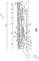
- FIG 2 is a partial schematic side view of a low pressure turbine shaft 100 that can be used as the low pressure turbine spool 44 for the gas turbine engine 20 of Figure 1 .
- the low pressure shaft 100 includes a shaft body 110 that can be cylindrical in nature and is aligned with the axis A.
- the shaft body 110 includes an internal opening 130 for receiving a power turbine shaft (not pictured).
- a high power turbine shaft 180 surrounds the low pressure turbine shaft 100 and defines an outer diameter clearance 182 that any radially protruding features of the low pressure turbine shaft 100 must be able to pass through. As a result of the narrow outer diameter clearance 182, there is insufficient radial clearance for a shoulder/spacer arrangement such as the one described above.
- the shaft body 110 includes a radially protruding threading section 120 with a radial height shorter than the outer diameter clearance 182. Disposed about the shaft body 110, is a variable positioner 140.
- the variable positioner 140 includes a section of radially inward facing threads 142.
- the radially inward facing threads 142 of the variable positioner 140 and the radially outward facing threads 120 of the shaft body 110 interface with each other.
- the axial position of the variable positioner 140 relative to the shaft body 110 can be adjusted via rotating the variable positioner 140 circumferentially about axis A, thereby causing the variable positioner 140 to shift axially via the threading interface.
- variable positioner 140 further includes one or more anti-rotation slots 146 on a radially exterior surface 147 of the variable positioner 140.
- the variable positioner 140 further includes a shoulder surface 148 that interfaces with a facing shoulder surface 172 of the rotor 170.
- the contact between the facing shoulder surface 172 and the shoulder surface 148 of the variable positioner 140 maintains the rotor 170 assembly in the correct axial position relative to the static hardware forward and aft of the rotor 170.
- the axial position of the variable positioner 140 can be adjusted, relative to the shaft body 110, by rotation of the variable positioner 140. In this way, the specific position of the rotor 170 can be adjusted to compensate for tolerances of the specific engine without requiring milling or other alterations to a stock variable positioner 140.
- a shaft spline interface 160 is also protruding radially outward from the shaft body 110.
- the shaft spline interface 160 interfaces with a rotor spline interface of a rotor arm 150 of the rotor 170 and allows for the transference of torque from the shaft body 110 to the rotor 170, or vice-versa.
- the anti-rotation slots 146 is a loose fit with the rotor 170, thereby allowing the anti-rotation slots 146 to prevent the variable positioner 140 from rotating, without imparting a torque transfer between the shaft body 110 and the rotor 170 at the anti-rotation slots 146.
- the shaft body 110 can include additional radially protruding features (not pictured).
- Each of the additional radially protruding features has a radial height less than the inner diameter bound 182, where the radial height is defined as the radial distance that the feature extends away from an outer surface 112 of the shaft body 110.
- Figure 3A illustrates a cross sectional view of a variable positioner 240.
- Figure 3B illustrates an axial end view of the variable positioner 240 of Figure 3A .
- the variable positioner 240 includes a cylindrical primary body section 296, with a first axial end surface 248 and a second axial end surface 290 opposite the first axial end surface 248 and a through hole protruding through the variable positioner 240.
- the through hole is axially aligned with the axis defined by the variable positioner.
- the first axial end surface 248 is positioned aft ward, relative to a corresponding shaft and serves as the contact surface for a corresponding rotor (such as the rotor 170 of Figure 2 ).
- the threading 242 is complementary to a threading feature of a corresponding shaft (such as the low turbine shaft 74 of Figure 1 ), and allows the variable positioner to be moved axially along the shaft when rotated relative to the shaft body. Similarly, the threading 242 prevents the variable positioner from shifting axially relative to the shaft body when the variable positioner 240 is not being rotated.
- a radially outward surface 292 of the variable positioner 240 includes multiple intrusions 293.
- Each of the intrusions 293 forms a slot that is operable to receive an anti-rotation feature of a rotor positioned axially by the variable positioner 240.
- the intrusions 293 extend a partial axial length of the variable positioner. In alternate examples, the intrusions 293 can extend the full axial length.
- the example variable positioner 240 includes four anti-rotation slots 293 disposed evenly about the exterior surface 292 of the variable positioner 240. Alternate examples can use more or fewer anti-rotation slots 293 depending on the particular needs of a given engine.
- the illustrated example variable positioner 240 includes a radially inward contact surface 294 that nearly contacts the shaft about which the variable positioner is disposed, thereby centering the variable positioner, and increasing the radial height of the shoulder surface 248 that interfaces with the corresponding rotor.
- Alternate example variable positioners can have the opening defined by the surface 294 be radially larger than the outer diameter of the shaft, thereby allowing the variable positioner 240 to be easily disposed about the shaft.
- variable positioner 240 of Figures 3A and 3B is illustrated as a cylindrical ring, it is understood that other three dimensional shapes including a basic cylindrical body can be utilized to the same effect.
Description
- The present disclosure relates generally to a variable positioner for positioning a rotor relative to a shaft.
- Gas turbine engines, such as those used on commercial and military aircraft, utilize multiple shafts to drive multiple compressor sections. Each of the shafts is connected to, and driven by, a turbine section. By way of example, some gas turbine engines include a high pressure turbine section that is connected to, and drives, a high pressure compressor section via a shaft and a low pressure turbine section that is connected to, and drives, a low pressure compressor section, a helicopter rotor, or another rotating component via another shaft. Alternate gas turbine engines can utilize additional compressor and turbine sections and an additional shaft.
- In a typical gas turbine engine construction, the shafts are nested to form a single multi-shaft assembly that runs through the core of the gas turbine engine. This assembly is alternately referred to as a multi-spool assembly. Turbine rotors and compressor rotors corresponding to each shaft are attached to the shaft via a feature such as a spline which transfers torque between the rotors and the shaft. The rotors are maintained in axial position relative to the shaft via a spacer that interfaces with an axial load bearing feature on the shaft and with a shoulder of the rotor.
In some examples, gas turbine engine size and weight constraints reduce the possible size of the radially protruding shoulder. In such a case, the shoulder/spacer arrangement described above can be insufficient to maintain the rotor position relative to the static hardware forward and aft of the rotor. -
US 3,997,962 describes a method and tool for removing a turbine from a twin spool gas turbine engine which has a pair of coaxially mounted shafts, the shafts being spaced apart to form an annular groove. The tool has retractable means adapted to be inserted in the annular groove. - A gas turbine engine, according to claim 1, is provided.
- In a further embodiment of the foregoing gas turbine engine, at least one of the first and second axial end surface of the variable positioner is an interface shoulder, and the interface shoulder interfaces with an interface surface of a rotating component, thereby maintaining the rotating component in position axially, relative to at least one static hardware component of the gas turbine engine.
- In a further embodiment of the foregoing gas turbine engine, the at least one anti-rotation slot is loose fit with the at least one anti-rotation feature such that torque is transferred between the rotor and the second shaft at a spline instead of at the anti-rotation feature.
- In a further embodiment of the foregoing gas turbine engine, the variable positioner includes at least one anti-rotation slot and the rotor includes at least one corresponding anti-rotation feature, and the at least one anti-rotation slot and the at least one corresponding anti-rotation feature are interfaced to form an anti-rotation assembly.
- In a further embodiment of the foregoing gas turbine engine, a clearance between an outer diameter of the second shaft and an inner diameter of the first shaft defines an outer diameter clearance to the second shaft.
- In a further embodiment of the foregoing gas turbine engine, the radially protruding threading portion has a radial height, and the radial height is less than the outer diameter clearance of the second shaft.
- A further embodiment of the foregoing gas turbine engine includes a power turbine section in fluid communication with the second turbine section and an output shaft, the power turbine section is connected to the output shaft via a third shaft, and the third shaft is disposed at least partially within the second shaft.
- A method of maintaining an axial position of a rotor, relative to at least one static engine component in a gas turbine engine, according to claim 8 is provided.
- In a further embodiment of the foregoing method, includes interfacing a rotor spline portion with a shaft spline portion, thereby facilitating transfer of torque between the rotor and the shaft at a spline without incurring a transfer of torque between the rotor and the shaft at the variable positioner.
- The foregoing features and elements may be combined in any combination without exclusivity, unless expressly indicated otherwise.
These and other features of the present invention can be best understood from the following specification and drawings, the following of which is a brief description. -
-
Figure 1 schematically illustrates a gas turbine engine. -
Figure 2 is a partial schematic side view of a shaft for the gas turbine engine ofFigure 1 . -
Figure 3A is a cross sectional side view of a variable positioner. -
Figure 3B is an axial end view of the variable positioner ofFigure 3A . -
Figure 1 schematically illustrates agas turbine engine 20. Thegas turbine engine 20 is disclosed herein as a variable cycle three-spool turbine that generally includes a low pressurecompressor fan section 26, a highpressure compressor section 28, acombustor section 30, a highpressure turbine section 32, an lowpressure turbine section 34, apower turbine section 36, abypass duct section 38 and anozzle section 40. Thepower turbine section 36 drives ahelicopter rotor 37. Additional sections may include anaugmentor section 38A among other systems or features such as a geared architecture which may be located in various other engine sections than that shown such as, for example, aft of the lowpressure turbine section 34. The sections are defined along a central longitudinal engine axis A. - The
engine 20 generally includes apower turbine spool 42, a lowpressure turbine spool 44 and a highpressure turbine spool 46 which rotate about the engine central longitudinal axis A relative to anengine case structure 48. It should be appreciated that other architectures, such as a two-spool architecture, will also benefit therefrom. - It should further be understood that various structures individual or collectively within the engine may define a
case structures 50 to define an exoskeleton that supports thespools - The low
pressure compressor section 26 communicates low pressure compressor flow into thecore flow path 60. The highpressure compressor section 28, thecombustor section 30, the highpressure turbine section 32, the lowpressure turbine section 34, and thepower turbine section 36 are in thecore flow path 60. - The core airflow is compressed by the low
pressure compressor section 26, the highpressure compressor section 28, mixed and burned with fuel in thecombustor section 30, then expanded over the highpressure turbine section 32, the lowpressure turbine section 34, and thepower turbine section 36. Theturbines pressure turbine spool 46, the lowpressure turbine spool 44, and the power turbine spool 42 in response to the expansion. Thepower turbine section 36 is coupled to apower turbine shaft 66. In one example, thepower turbine shaft 66 is coupled to a helicopter rotor and provides a rotational input to the helicopter rotor. In alternate examples, thepower turbine shaft 66 is an output shaft that provides rotation to another system, such as an electrical generator. - In some instances a second
stream bypass duct 54 is defined by anouter case structure 50 and theinner case structure 54. Thecore flow path 60 is generally defined by theinner case structure 54. - The low
pressure compressor section 26 and the lowpressure turbine section 34 are coupled by a low pressure turbine shaft 74 to define the lowpressure turbine spool 44. In the example ofFigure 1 , the lowpressure compressor section 26 includes a low pressure compressor variableinlet guide vane 76, a lowpressure compressor rotor 78, and a lowpressure compressor stator 80. It should be understood that other gas turbine engine architectures may alternatively or additionally be provided such as various combinations of a fixed or variable low pressure compressor, variableinlet guide vane 76, and a fixed or variable low pressure compressor stator. - The high
pressure compressor section 28 and the highpressure turbine section 32 are coupled by ahigh shaft 82 to define the highpressure turbine spool 46. In the example ofFigure 1 , the highpressure compressor section 28 upstream of thecombustor section 30 includes multiple of stages, each with arotor 84 andvane 86. - The high
pressure compressor section 28 may alternatively, or additionally, include other compressor section architectures that include additional or fewer stages each with or without various combinations of variable or fixed guide vanes. Furthermore, each of theturbine sections pressure turbine section 32 in the example ofFigure 1 , includes multiple stages with variable high pressure turbine guide vanes (high pressure turbine vanes) 88 between a first stage high pressure turbine rotor 90 and a second stage high pressure turbine rotor 92. - Essentially all flow from the low
pressure compressor section 26 is communicated into thecore flow path 60. - Due to the multi-shaft arrangement of the
gas turbine engine 20, thepower turbine spool 42 is contained within the lowpressure turbine spool 44, and the lowpressure turbine spool 44 is contained within the highpower turbine spool 46. This arrangement ofshafts - During assembly of the
gas turbine engine 20, the core is constructed first, andturbine shafts 66, 74 are installed. In one example, thelow pressure turbine 34 is installed after low pressure shaft 74 and before thepower turbine shaft 66 is installed. As a result of this assembly procedure, the low pressure turbine shaft 74 has a maximum outer diameter boundary defined by an internal radius of the highpressure turbine shaft 82. Similarly, the low pressure turbine shaft 74 has a minimum internal radius defined by the features of thepower turbine shaft 66 that passes through the low pressure turbine shaft 74. - In a typical gas turbine engine, the low pressure turbine shaft 74 is connected to the
rotors 96 in the lowpressure turbine section 34 via a spline. The shaft 74 includes a shoulder that extends radially outward from the shaft and defines an axial positioning surface. The axial positioning surface of the shoulder interfaces with a spacer component that is disposed about the shaft 74. The spacer component in turn interfaces with a feature of the low pressure turbine rotor to maintain the rotor in position axially. Existing spacer components come in classified sizes and are machined to particular tolerances once the specific spacing needed for a given engine is determined. - In an
engine 20 where the outer diameter bound of the low pressure turbine shaft 74 is small due to height and/or weight constraints, the maximum possible radial height of the outer diameter shoulder can be too small to sufficiently prevent axial motion of the low pressureturbine section rotor 96 without damage occurring to the shoulder. Therefore, the typical design cannot maintain the required axial position of the lowpressure turbine rotor 96 when theengine 20 is under strict height/weight constraints. -
Figure 2 is a partial schematic side view of a lowpressure turbine shaft 100 that can be used as the lowpressure turbine spool 44 for thegas turbine engine 20 ofFigure 1 . Thelow pressure shaft 100 includes ashaft body 110 that can be cylindrical in nature and is aligned with the axis A. Theshaft body 110 includes aninternal opening 130 for receiving a power turbine shaft (not pictured). A highpower turbine shaft 180 surrounds the lowpressure turbine shaft 100 and defines anouter diameter clearance 182 that any radially protruding features of the lowpressure turbine shaft 100 must be able to pass through. As a result of the narrowouter diameter clearance 182, there is insufficient radial clearance for a shoulder/spacer arrangement such as the one described above. - The
shaft body 110 includes a radially protrudingthreading section 120 with a radial height shorter than theouter diameter clearance 182. Disposed about theshaft body 110, is avariable positioner 140. Thevariable positioner 140 includes a section of radially inward facingthreads 142. The radially inward facingthreads 142 of thevariable positioner 140 and the radially outward facingthreads 120 of theshaft body 110 interface with each other. The axial position of thevariable positioner 140 relative to theshaft body 110 can be adjusted via rotating thevariable positioner 140 circumferentially about axis A, thereby causing thevariable positioner 140 to shift axially via the threading interface. - The
variable positioner 140 further includes one or moreanti-rotation slots 146 on a radiallyexterior surface 147 of thevariable positioner 140. - The
variable positioner 140 further includes a shoulder surface 148 that interfaces with a facing shoulder surface 172 of therotor 170. The contact between the facing shoulder surface 172 and the shoulder surface 148 of thevariable positioner 140 maintains therotor 170 assembly in the correct axial position relative to the static hardware forward and aft of therotor 170. As described above, the axial position of thevariable positioner 140 can be adjusted, relative to theshaft body 110, by rotation of thevariable positioner 140. In this way, the specific position of therotor 170 can be adjusted to compensate for tolerances of the specific engine without requiring milling or other alterations to astock variable positioner 140. - Also protruding radially outward from the
shaft body 110 is ashaft spline interface 160. Theshaft spline interface 160 interfaces with a rotor spline interface of arotor arm 150 of therotor 170 and allows for the transference of torque from theshaft body 110 to therotor 170, or vice-versa. In some examples, theanti-rotation slots 146 is a loose fit with therotor 170, thereby allowing theanti-rotation slots 146 to prevent thevariable positioner 140 from rotating, without imparting a torque transfer between theshaft body 110 and therotor 170 at theanti-rotation slots 146. - Furthermore, the
shaft body 110 can include additional radially protruding features (not pictured). Each of the additional radially protruding features has a radial height less than the inner diameter bound 182, where the radial height is defined as the radial distance that the feature extends away from anouter surface 112 of theshaft body 110. -
Figure 3A illustrates a cross sectional view of avariable positioner 240. Similarly,Figure 3B illustrates an axial end view of thevariable positioner 240 ofFigure 3A . In the illustrated examples, thevariable positioner 240 includes a cylindricalprimary body section 296, with a firstaxial end surface 248 and a secondaxial end surface 290 opposite the firstaxial end surface 248 and a through hole protruding through thevariable positioner 240. The through hole is axially aligned with the axis defined by the variable positioner. In a typical example, the firstaxial end surface 248 is positioned aft ward, relative to a corresponding shaft and serves as the contact surface for a corresponding rotor (such as therotor 170 ofFigure 2 ). - Protruding radially inward from the
primary body 296 of thevariable positioner 240 is a threading 242. The threading 242 is complementary to a threading feature of a corresponding shaft (such as the low turbine shaft 74 ofFigure 1 ), and allows the variable positioner to be moved axially along the shaft when rotated relative to the shaft body. Similarly, the threading 242 prevents the variable positioner from shifting axially relative to the shaft body when thevariable positioner 240 is not being rotated. - A radially
outward surface 292 of thevariable positioner 240, includesmultiple intrusions 293. Each of theintrusions 293 forms a slot that is operable to receive an anti-rotation feature of a rotor positioned axially by thevariable positioner 240. In the illustrated example, theintrusions 293 extend a partial axial length of the variable positioner. In alternate examples, theintrusions 293 can extend the full axial length. As seen inFigure 3B , theexample variable positioner 240 includes fouranti-rotation slots 293 disposed evenly about theexterior surface 292 of thevariable positioner 240. Alternate examples can use more or feweranti-rotation slots 293 depending on the particular needs of a given engine. - The illustrated example
variable positioner 240 includes a radiallyinward contact surface 294 that nearly contacts the shaft about which the variable positioner is disposed, thereby centering the variable positioner, and increasing the radial height of theshoulder surface 248 that interfaces with the corresponding rotor. Alternate example variable positioners can have the opening defined by thesurface 294 be radially larger than the outer diameter of the shaft, thereby allowing thevariable positioner 240 to be easily disposed about the shaft. - While the
example variable positioner 240 ofFigures 3A and 3B is illustrated as a cylindrical ring, it is understood that other three dimensional shapes including a basic cylindrical body can be utilized to the same effect. - While the above description is written towards a three-spool gas turbine engine architecture, it will be understood by one of skill in the art that the illustrated shaft design and variable positioner can be adapted to any machine, including two-spool turbo machines, and still fall within the above disclosure.
- It is further understood that any of the above described concepts can be used alone or in combination with any or all of the other above described concepts. Although an embodiment of this invention has been disclosed, a worker of ordinary skill in this art would recognize that certain modifications would come within the scope of this invention. For that reason, the following claims should be studied to determine the true scope and content of this invention.
Claims (9)
- A gas turbine engine (20) comprising:a compressor section having at least a first compressor portion (28) and a second compressor portion (26);a combustor (30) fluidly connected to the compressor section;a turbine section fluidly connected to the combustor section, the turbine section having at least a first turbine portion (32) and a second turbine portion (34);a first shaft (46) connecting the first compressor section (28) and the first turbine section (32);a second shaft (100) connecting the second compressor section (26) and the second turbine section (34), wherein the second shaft (100) is at least partially disposed within the first shaft (46), and wherein the second shaft (100) includes a radially protruding threading portion (120); and
a variable positioner (140; 240) disposed about said second shaft (100), the variable positioner (140; 240) being a cylindrical component defining a radially outward facing surface (147; 292) and a first and second axial end surface (148; 248, 290), wherein the variable positioner (140; 240) includes a radially inward facing threading section (142; 242), and wherein said radially inward facing threading section (142; 242) of said variable positioner (100; 240) interfaces with said radially protruding threading portion (120) of said second shaft (100), wherein said variable positioner (240) further comprises at least one anti-rotation slot (146; 293) positioned on said radially outward facing surface (147; 292), the anti-rotation slot interfacing with an interface surface of a rotating component; wherein said at least one anti-rotation slot (146; 293) interfaces with an anti-rotation feature of said rotor, thereby preventing rotation of the variable positioner relative to the second shaft,
a rotor (170) having an interface surface (172) contacting a surface (148; 248) of said variable positioner (140; 240). - The gas turbine engine of claim 1, wherein at least one (148; 248) of the first and second axial end surface of the variable positioner is an interface shoulder, and wherein the interface shoulder (148; 248) interfaces with an interface surface (172) of said rotor (170), thereby maintaining said rotor in position axially, relative to at least one static hardware component of the gas turbine engine.
- The gas turbine engine of claim 1, wherein said at least one anti-rotation slot (146; 293) is loose fit with said at least one anti-rotation feature such that torque is transferred between said rotor and said second shaft (100) at a spline instead of at said anti-rotation feature.
- The gas turbine engine of any preceding claim, wherein;
said rotor (170) further includes a rotor spline;
the second shaft (100) includes a shaft spline (160); and
the rotor spline and the shaft spline (160) are interfaced together allowing the transfer of torque between the shaft (100) and the rotor (170). - The gas turbine engine of any preceding claim, wherein a clearance (182) between an outer diameter of said second shaft (100) and an inner diameter of said first shaft (46) defines an outer diameter clearance to the second shaft (100).
- The gas turbine engine of claim 5, wherein said radially protruding threading portion (120) has a radial height, and wherein said radial height (120) is less than said outer diameter clearance of the second shaft (100).
- The gas turbine engine of any preceding claim, further comprising a power turbine section (36) in fluid communication with the second turbine section (34) and an output shaft (66), wherein the power turbine section (36) is connected to the output shaft (66) via a third shaft (42), and wherein the third shaft (42) is disposed at least partially within the second shaft (100).
- A method of maintaining an axial position of a rotor, relative to at least one static engine component, in a gas turbine engine comprising:disposing a variable positioner (140; 240) about a shaft (100), such that a radially inward facing threading (142; 242) of said variable positioner (140; 240) interfaces with a radially outward facing threading (120) of said shaft (100);rotating said variable positioner (140; 240), thereby shifting the variable positioner (140; 240) axially along said shaft (100), until an interface surface (148; 248) of said variable positioner (140; 240) is in a desired position; andinterfacing a rotor (170) with said interface surface (148; 248) of said variable positioner (140; 240), thereby maintaining said rotor (70) in an axial position relative to said shaft (100) and interfacing an anti-rotation feature of said rotor with an anti-rotation slot (146, 293) of said variable positioner (140, 240), thereby preventing rotation of said variable positioner (140, 240) relative to said shaft (100), wherein the anti-rotation slot is located on a radially outward facing surface of said variable positioner;interfacing an anti-rotation feature of said rotor with an anti-rotation slot (146; 293) of said variable positioner (140; 240), thereby preventing rotation of said variable positioner (140; 240) relative to said shaft (100).
- The method of claim 8,
further comprising interfacing a rotor spline portion with a shaft spline portion (160), thereby facilitating transfer of torque between the rotor (170) and the shaft (100) at a spline without incurring a transfer of torque between the rotor (170) and the shaft (100) at the variable positioner (140; 240).
Applications Claiming Priority (1)
| Application Number | Priority Date | Filing Date | Title |
|---|---|---|---|
| US201461934871P | 2014-02-03 | 2014-02-03 |
Publications (2)
| Publication Number | Publication Date |
|---|---|
| EP2902587A1 EP2902587A1 (en) | 2015-08-05 |
| EP2902587B1 true EP2902587B1 (en) | 2018-12-12 |
Family
ID=52465206
Family Applications (1)
| Application Number | Title | Priority Date | Filing Date |
|---|---|---|---|
| EP15153494.8A Active EP2902587B1 (en) | 2014-02-03 | 2015-02-02 | Variable positioner |
Country Status (2)
| Country | Link |
|---|---|
| US (1) | US10428690B2 (en) |
| EP (1) | EP2902587B1 (en) |
Families Citing this family (4)
| Publication number | Priority date | Publication date | Assignee | Title |
|---|---|---|---|---|
| US10267152B2 (en) * | 2013-09-16 | 2019-04-23 | United Technologies Corporation | Piloted nut |
| US10753281B2 (en) * | 2017-11-21 | 2020-08-25 | Raytheon Technologies Corporation | Ablatable shaft feature in a gas turbine engine |
| FR3087820B1 (en) * | 2018-10-26 | 2020-10-16 | Safran Aircraft Engines | AIRCRAFT TURBOMACHINE EQUIPPED WITH AN ELECTRIC MACHINE |
| US11629596B1 (en) | 2021-10-08 | 2023-04-18 | Pratt & Whitney Canada Corp. | Rotor assembly for a gas turbine engine and method for assembling same |
Family Cites Families (12)
| Publication number | Priority date | Publication date | Assignee | Title |
|---|---|---|---|---|
| US1570002A (en) * | 1925-04-23 | 1926-01-19 | Joseph M Perry | Nut lock |
| US3188807A (en) | 1962-10-05 | 1965-06-15 | Bendix Corp | Variable torque transmitting mechanism for a re-expansion gas turbine |
| GB1092516A (en) * | 1965-09-29 | 1967-11-29 | Rolls Royce | Apparatus for locking two members |
| US3730640A (en) * | 1971-06-28 | 1973-05-01 | United Aircraft Corp | Seal ring for gas turbine |
| US3892500A (en) | 1974-07-10 | 1975-07-01 | Westinghouse Electric Corp | Adjustable axial positioning device |
| US3997962A (en) * | 1975-06-06 | 1976-12-21 | United Technologies Corporation | Method and tool for removing turbine from gas turbine twin spool engine |
| GB2057631B (en) * | 1979-08-31 | 1983-03-16 | Rolls Royce | Shaft coupling |
| GB8706905D0 (en) | 1987-03-24 | 1987-04-29 | Schlumberger Electronics Uk | Shaft monitoring system |
| GB0002257D0 (en) * | 2000-02-02 | 2000-03-22 | Rolls Royce Plc | Rotary apparatus for a gas turbine engine |
| DE10225958B3 (en) | 2002-06-12 | 2004-03-04 | Bruker Biospin Ag | Apparatus for positioning an elongate sample tube filled with a measurement substance relative to a NMR receiver coil system |
| US8287242B2 (en) | 2008-11-17 | 2012-10-16 | United Technologies Corporation | Turbine engine rotor hub |
| US8408082B2 (en) | 2009-11-18 | 2013-04-02 | General Electric Company | Apparatus to measure fluids in a conduit |
-
2015
- 2015-02-02 EP EP15153494.8A patent/EP2902587B1/en active Active
- 2015-02-02 US US14/611,369 patent/US10428690B2/en active Active
Non-Patent Citations (1)
| Title |
|---|
| None * |
Also Published As
| Publication number | Publication date |
|---|---|
| EP2902587A1 (en) | 2015-08-05 |
| US20150218965A1 (en) | 2015-08-06 |
| US10428690B2 (en) | 2019-10-01 |
Similar Documents
| Publication | Publication Date | Title |
|---|---|---|
| US10487747B2 (en) | Modular assembly for a turbine engine | |
| EP3029358A1 (en) | Lightweight and compliant journal pin | |
| EP2817490B1 (en) | Vane assembly for a gas turbine engine | |
| EP3594454A1 (en) | Non-contact seal with removal features | |
| US10077660B2 (en) | Turbine engine assembly and method of manufacturing | |
| EP2902587B1 (en) | Variable positioner | |
| EP2855893B1 (en) | Geared architecture carrier torque frame assembly | |
| US20140069100A1 (en) | Compact double grounded mechanical carbon seal | |
| US11230942B2 (en) | Gas turbine engine electrical generator | |
| EP2587020B1 (en) | Journal pin for gear system | |
| EP3670860B1 (en) | Fan and low pressure compressor geared to a low speed spool of a gas turbine engine | |
| EP2917508B1 (en) | Gas turbine engine with a compressor bleed air slot | |
| EP2880282B1 (en) | Compressor assembly with stator anti-rotation lug | |
| EP2906807B1 (en) | Geared turbofan engine with inter-shaft deflection feature | |
| EP3078815B1 (en) | Active clearance control for axial rotor systems | |
| EP3246517B1 (en) | Fastener openings for stress distribution | |
| EP2971697B1 (en) | Distributed engine accessory drive | |
| US11118535B2 (en) | Reversing gear assembly for a turbo machine | |
| EP3401562B1 (en) | Bearing with non-uniform cage clearance | |
| EP3054090B1 (en) | Gas turbine engines with internally stretched tie shafts | |
| EP3112634B1 (en) | Advanced distributed engine architecture-design alternative | |
| EP3578781B1 (en) | Multiple mounting surface gearbox | |
| EP3626935B1 (en) | A speed change mechanism for a gas turbine engine | |
| EP3404215A1 (en) | Seal anti-rotation |
Legal Events
| Date | Code | Title | Description |
|---|---|---|---|
| PUAI | Public reference made under article 153(3) epc to a published international application that has entered the european phase |
Free format text: ORIGINAL CODE: 0009012 |
|
| 17P | Request for examination filed |
Effective date: 20150202 |
|
| AK | Designated contracting states |
Kind code of ref document: A1 Designated state(s): AL AT BE BG CH CY CZ DE DK EE ES FI FR GB GR HR HU IE IS IT LI LT LU LV MC MK MT NL NO PL PT RO RS SE SI SK SM TR |
|
| AX | Request for extension of the european patent |
Extension state: BA ME |
|
| 17P | Request for examination filed |
Effective date: 20160202 |
|
| RBV | Designated contracting states (corrected) |
Designated state(s): AL AT BE BG CH CY CZ DE DK EE ES FI FR GB GR HR HU IE IS IT LI LT LU LV MC MK MT NL NO PL PT RO RS SE SI SK SM TR |
|
| RAP1 | Party data changed (applicant data changed or rights of an application transferred) |
Owner name: UNITED TECHNOLOGIES CORPORATION |
|
| STAA | Information on the status of an ep patent application or granted ep patent |
Free format text: STATUS: EXAMINATION IS IN PROGRESS |
|
| 17Q | First examination report despatched |
Effective date: 20171212 |
|
| RIC1 | Information provided on ipc code assigned before grant |
Ipc: F02C 7/36 20060101ALI20180531BHEP Ipc: F01D 5/02 20060101AFI20180531BHEP Ipc: F02C 3/107 20060101ALI20180531BHEP |
|
| GRAP | Despatch of communication of intention to grant a patent |
Free format text: ORIGINAL CODE: EPIDOSNIGR1 |
|
| STAA | Information on the status of an ep patent application or granted ep patent |
Free format text: STATUS: GRANT OF PATENT IS INTENDED |
|
| INTG | Intention to grant announced |
Effective date: 20180710 |
|
| GRAS | Grant fee paid |
Free format text: ORIGINAL CODE: EPIDOSNIGR3 |
|
| GRAA | (expected) grant |
Free format text: ORIGINAL CODE: 0009210 |
|
| STAA | Information on the status of an ep patent application or granted ep patent |
Free format text: STATUS: THE PATENT HAS BEEN GRANTED |
|
| AK | Designated contracting states |
Kind code of ref document: B1 Designated state(s): AL AT BE BG CH CY CZ DE DK EE ES FI FR GB GR HR HU IE IS IT LI LT LU LV MC MK MT NL NO PL PT RO RS SE SI SK SM TR |
|
| REG | Reference to a national code |
Ref country code: GB Ref legal event code: FG4D |
|
| REG | Reference to a national code |
Ref country code: CH Ref legal event code: EP |
|
| REG | Reference to a national code |
Ref country code: AT Ref legal event code: REF Ref document number: 1076241 Country of ref document: AT Kind code of ref document: T Effective date: 20181215 |
|
| REG | Reference to a national code |
Ref country code: DE Ref legal event code: R096 Ref document number: 602015021129 Country of ref document: DE |
|
| REG | Reference to a national code |
Ref country code: IE Ref legal event code: FG4D |
|
| REG | Reference to a national code |
Ref country code: NL Ref legal event code: MP Effective date: 20181212 |
|
| REG | Reference to a national code |
Ref country code: LT Ref legal event code: MG4D |
|
| PG25 | Lapsed in a contracting state [announced via postgrant information from national office to epo] |
Ref country code: FI Free format text: LAPSE BECAUSE OF FAILURE TO SUBMIT A TRANSLATION OF THE DESCRIPTION OR TO PAY THE FEE WITHIN THE PRESCRIBED TIME-LIMIT Effective date: 20181212 Ref country code: LT Free format text: LAPSE BECAUSE OF FAILURE TO SUBMIT A TRANSLATION OF THE DESCRIPTION OR TO PAY THE FEE WITHIN THE PRESCRIBED TIME-LIMIT Effective date: 20181212 Ref country code: BG Free format text: LAPSE BECAUSE OF FAILURE TO SUBMIT A TRANSLATION OF THE DESCRIPTION OR TO PAY THE FEE WITHIN THE PRESCRIBED TIME-LIMIT Effective date: 20190312 Ref country code: HR Free format text: LAPSE BECAUSE OF FAILURE TO SUBMIT A TRANSLATION OF THE DESCRIPTION OR TO PAY THE FEE WITHIN THE PRESCRIBED TIME-LIMIT Effective date: 20181212 Ref country code: LV Free format text: LAPSE BECAUSE OF FAILURE TO SUBMIT A TRANSLATION OF THE DESCRIPTION OR TO PAY THE FEE WITHIN THE PRESCRIBED TIME-LIMIT Effective date: 20181212 Ref country code: ES Free format text: LAPSE BECAUSE OF FAILURE TO SUBMIT A TRANSLATION OF THE DESCRIPTION OR TO PAY THE FEE WITHIN THE PRESCRIBED TIME-LIMIT Effective date: 20181212 Ref country code: NO Free format text: LAPSE BECAUSE OF FAILURE TO SUBMIT A TRANSLATION OF THE DESCRIPTION OR TO PAY THE FEE WITHIN THE PRESCRIBED TIME-LIMIT Effective date: 20190312 |
|
| REG | Reference to a national code |
Ref country code: AT Ref legal event code: MK05 Ref document number: 1076241 Country of ref document: AT Kind code of ref document: T Effective date: 20181212 |
|
| PG25 | Lapsed in a contracting state [announced via postgrant information from national office to epo] |
Ref country code: GR Free format text: LAPSE BECAUSE OF FAILURE TO SUBMIT A TRANSLATION OF THE DESCRIPTION OR TO PAY THE FEE WITHIN THE PRESCRIBED TIME-LIMIT Effective date: 20190313 Ref country code: RS Free format text: LAPSE BECAUSE OF FAILURE TO SUBMIT A TRANSLATION OF THE DESCRIPTION OR TO PAY THE FEE WITHIN THE PRESCRIBED TIME-LIMIT Effective date: 20181212 Ref country code: AL Free format text: LAPSE BECAUSE OF FAILURE TO SUBMIT A TRANSLATION OF THE DESCRIPTION OR TO PAY THE FEE WITHIN THE PRESCRIBED TIME-LIMIT Effective date: 20181212 Ref country code: SE Free format text: LAPSE BECAUSE OF FAILURE TO SUBMIT A TRANSLATION OF THE DESCRIPTION OR TO PAY THE FEE WITHIN THE PRESCRIBED TIME-LIMIT Effective date: 20181212 |
|
| PG25 | Lapsed in a contracting state [announced via postgrant information from national office to epo] |
Ref country code: NL Free format text: LAPSE BECAUSE OF FAILURE TO SUBMIT A TRANSLATION OF THE DESCRIPTION OR TO PAY THE FEE WITHIN THE PRESCRIBED TIME-LIMIT Effective date: 20181212 |
|
| PG25 | Lapsed in a contracting state [announced via postgrant information from national office to epo] |
Ref country code: IT Free format text: LAPSE BECAUSE OF FAILURE TO SUBMIT A TRANSLATION OF THE DESCRIPTION OR TO PAY THE FEE WITHIN THE PRESCRIBED TIME-LIMIT Effective date: 20181212 Ref country code: CZ Free format text: LAPSE BECAUSE OF FAILURE TO SUBMIT A TRANSLATION OF THE DESCRIPTION OR TO PAY THE FEE WITHIN THE PRESCRIBED TIME-LIMIT Effective date: 20181212 Ref country code: PT Free format text: LAPSE BECAUSE OF FAILURE TO SUBMIT A TRANSLATION OF THE DESCRIPTION OR TO PAY THE FEE WITHIN THE PRESCRIBED TIME-LIMIT Effective date: 20190412 Ref country code: PL Free format text: LAPSE BECAUSE OF FAILURE TO SUBMIT A TRANSLATION OF THE DESCRIPTION OR TO PAY THE FEE WITHIN THE PRESCRIBED TIME-LIMIT Effective date: 20181212 |
|
| PG25 | Lapsed in a contracting state [announced via postgrant information from national office to epo] |
Ref country code: SK Free format text: LAPSE BECAUSE OF FAILURE TO SUBMIT A TRANSLATION OF THE DESCRIPTION OR TO PAY THE FEE WITHIN THE PRESCRIBED TIME-LIMIT Effective date: 20181212 Ref country code: EE Free format text: LAPSE BECAUSE OF FAILURE TO SUBMIT A TRANSLATION OF THE DESCRIPTION OR TO PAY THE FEE WITHIN THE PRESCRIBED TIME-LIMIT Effective date: 20181212 Ref country code: SM Free format text: LAPSE BECAUSE OF FAILURE TO SUBMIT A TRANSLATION OF THE DESCRIPTION OR TO PAY THE FEE WITHIN THE PRESCRIBED TIME-LIMIT Effective date: 20181212 Ref country code: IS Free format text: LAPSE BECAUSE OF FAILURE TO SUBMIT A TRANSLATION OF THE DESCRIPTION OR TO PAY THE FEE WITHIN THE PRESCRIBED TIME-LIMIT Effective date: 20190412 Ref country code: RO Free format text: LAPSE BECAUSE OF FAILURE TO SUBMIT A TRANSLATION OF THE DESCRIPTION OR TO PAY THE FEE WITHIN THE PRESCRIBED TIME-LIMIT Effective date: 20181212 |
|
| REG | Reference to a national code |
Ref country code: DE Ref legal event code: R097 Ref document number: 602015021129 Country of ref document: DE |
|
| REG | Reference to a national code |
Ref country code: CH Ref legal event code: PL |
|
| PLBE | No opposition filed within time limit |
Free format text: ORIGINAL CODE: 0009261 |
|
| STAA | Information on the status of an ep patent application or granted ep patent |
Free format text: STATUS: NO OPPOSITION FILED WITHIN TIME LIMIT |
|
| PG25 | Lapsed in a contracting state [announced via postgrant information from national office to epo] |
Ref country code: AT Free format text: LAPSE BECAUSE OF FAILURE TO SUBMIT A TRANSLATION OF THE DESCRIPTION OR TO PAY THE FEE WITHIN THE PRESCRIBED TIME-LIMIT Effective date: 20181212 Ref country code: MC Free format text: LAPSE BECAUSE OF FAILURE TO SUBMIT A TRANSLATION OF THE DESCRIPTION OR TO PAY THE FEE WITHIN THE PRESCRIBED TIME-LIMIT Effective date: 20181212 Ref country code: LU Free format text: LAPSE BECAUSE OF NON-PAYMENT OF DUE FEES Effective date: 20190202 Ref country code: SI Free format text: LAPSE BECAUSE OF FAILURE TO SUBMIT A TRANSLATION OF THE DESCRIPTION OR TO PAY THE FEE WITHIN THE PRESCRIBED TIME-LIMIT Effective date: 20181212 Ref country code: DK Free format text: LAPSE BECAUSE OF FAILURE TO SUBMIT A TRANSLATION OF THE DESCRIPTION OR TO PAY THE FEE WITHIN THE PRESCRIBED TIME-LIMIT Effective date: 20181212 |
|
| 26N | No opposition filed |
Effective date: 20190913 |
|
| REG | Reference to a national code |
Ref country code: BE Ref legal event code: MM Effective date: 20190228 |
|
| REG | Reference to a national code |
Ref country code: IE Ref legal event code: MM4A |
|
| PG25 | Lapsed in a contracting state [announced via postgrant information from national office to epo] |
Ref country code: CH Free format text: LAPSE BECAUSE OF NON-PAYMENT OF DUE FEES Effective date: 20190228 Ref country code: LI Free format text: LAPSE BECAUSE OF NON-PAYMENT OF DUE FEES Effective date: 20190228 |
|
| PG25 | Lapsed in a contracting state [announced via postgrant information from national office to epo] |
Ref country code: IE Free format text: LAPSE BECAUSE OF NON-PAYMENT OF DUE FEES Effective date: 20190202 |
|
| PG25 | Lapsed in a contracting state [announced via postgrant information from national office to epo] |
Ref country code: BE Free format text: LAPSE BECAUSE OF NON-PAYMENT OF DUE FEES Effective date: 20190228 |
|
| PG25 | Lapsed in a contracting state [announced via postgrant information from national office to epo] |
Ref country code: TR Free format text: LAPSE BECAUSE OF FAILURE TO SUBMIT A TRANSLATION OF THE DESCRIPTION OR TO PAY THE FEE WITHIN THE PRESCRIBED TIME-LIMIT Effective date: 20181212 |
|
| PG25 | Lapsed in a contracting state [announced via postgrant information from national office to epo] |
Ref country code: MT Free format text: LAPSE BECAUSE OF NON-PAYMENT OF DUE FEES Effective date: 20190202 |
|
| PG25 | Lapsed in a contracting state [announced via postgrant information from national office to epo] |
Ref country code: CY Free format text: LAPSE BECAUSE OF FAILURE TO SUBMIT A TRANSLATION OF THE DESCRIPTION OR TO PAY THE FEE WITHIN THE PRESCRIBED TIME-LIMIT Effective date: 20181212 |
|
| PG25 | Lapsed in a contracting state [announced via postgrant information from national office to epo] |
Ref country code: HU Free format text: LAPSE BECAUSE OF FAILURE TO SUBMIT A TRANSLATION OF THE DESCRIPTION OR TO PAY THE FEE WITHIN THE PRESCRIBED TIME-LIMIT; INVALID AB INITIO Effective date: 20150202 |
|
| PG25 | Lapsed in a contracting state [announced via postgrant information from national office to epo] |
Ref country code: MK Free format text: LAPSE BECAUSE OF FAILURE TO SUBMIT A TRANSLATION OF THE DESCRIPTION OR TO PAY THE FEE WITHIN THE PRESCRIBED TIME-LIMIT Effective date: 20181212 |
|
| REG | Reference to a national code |
Ref country code: DE Ref legal event code: R081 Ref document number: 602015021129 Country of ref document: DE Owner name: RAYTHEON TECHNOLOGIES CORPORATION (N.D.GES.D.S, US Free format text: FORMER OWNER: UNITED TECHNOLOGIES CORPORATION, FARMINGTON, CONN., US |
|
| PGFP | Annual fee paid to national office [announced via postgrant information from national office to epo] |
Ref country code: FR Payment date: 20230119 Year of fee payment: 9 |
|
| PGFP | Annual fee paid to national office [announced via postgrant information from national office to epo] |
Ref country code: GB Payment date: 20230121 Year of fee payment: 9 Ref country code: DE Payment date: 20230119 Year of fee payment: 9 |
|
| P01 | Opt-out of the competence of the unified patent court (upc) registered |
Effective date: 20230520 |