EP2902377A1 - Piezoelectric ceramic, method for manufacturing the same, piezoelectric element, and electronic apparatus - Google Patents
Piezoelectric ceramic, method for manufacturing the same, piezoelectric element, and electronic apparatus Download PDFInfo
- Publication number
- EP2902377A1 EP2902377A1 EP15000064.4A EP15000064A EP2902377A1 EP 2902377 A1 EP2902377 A1 EP 2902377A1 EP 15000064 A EP15000064 A EP 15000064A EP 2902377 A1 EP2902377 A1 EP 2902377A1
- Authority
- EP
- European Patent Office
- Prior art keywords
- piezoelectric ceramic
- piezoelectric
- ceramic
- piezoelectric element
- set forth
- Prior art date
- Legal status (The legal status is an assumption and is not a legal conclusion. Google has not performed a legal analysis and makes no representation as to the accuracy of the status listed.)
- Granted
Links
- 239000000919 ceramic Substances 0.000 title claims abstract description 281
- 238000000034 method Methods 0.000 title claims description 35
- 238000004519 manufacturing process Methods 0.000 title claims description 13
- 230000010287 polarization Effects 0.000 claims abstract description 68
- 229910044991 metal oxide Inorganic materials 0.000 claims abstract description 28
- 150000004706 metal oxides Chemical class 0.000 claims abstract description 28
- 229910002113 barium titanate Inorganic materials 0.000 claims abstract description 27
- JRPBQTZRNDNNOP-UHFFFAOYSA-N barium titanate Chemical compound [Ba+2].[Ba+2].[O-][Ti]([O-])([O-])[O-] JRPBQTZRNDNNOP-UHFFFAOYSA-N 0.000 claims abstract description 26
- 238000002441 X-ray diffraction Methods 0.000 claims abstract description 16
- 239000007788 liquid Substances 0.000 claims description 77
- 238000005259 measurement Methods 0.000 claims description 64
- 239000000428 dust Substances 0.000 claims description 45
- 239000000463 material Substances 0.000 claims description 41
- 230000008878 coupling Effects 0.000 claims description 37
- 238000010168 coupling process Methods 0.000 claims description 37
- 238000005859 coupling reaction Methods 0.000 claims description 37
- 230000003287 optical effect Effects 0.000 claims description 34
- 239000000843 powder Substances 0.000 claims description 34
- 239000002994 raw material Substances 0.000 claims description 15
- 238000001816 cooling Methods 0.000 claims description 12
- 229910052751 metal Inorganic materials 0.000 claims description 10
- 239000002184 metal Substances 0.000 claims description 10
- 238000010438 heat treatment Methods 0.000 claims description 9
- 238000005245 sintering Methods 0.000 claims description 8
- 238000012546 transfer Methods 0.000 claims description 6
- 230000000052 comparative effect Effects 0.000 description 59
- 239000013078 crystal Substances 0.000 description 39
- 239000011575 calcium Substances 0.000 description 26
- 239000011572 manganese Substances 0.000 description 22
- 239000010936 titanium Substances 0.000 description 22
- 150000001875 compounds Chemical class 0.000 description 19
- 239000000203 mixture Substances 0.000 description 18
- 230000005684 electric field Effects 0.000 description 16
- 229910052719 titanium Inorganic materials 0.000 description 13
- 238000011156 evaluation Methods 0.000 description 11
- 238000002360 preparation method Methods 0.000 description 11
- 229910052788 barium Inorganic materials 0.000 description 10
- 229910052791 calcium Inorganic materials 0.000 description 9
- 239000000470 constituent Substances 0.000 description 9
- 230000007423 decrease Effects 0.000 description 9
- 239000010931 gold Substances 0.000 description 9
- 239000011230 binding agent Substances 0.000 description 8
- 238000006073 displacement reaction Methods 0.000 description 8
- 239000010410 layer Substances 0.000 description 8
- 230000005855 radiation Effects 0.000 description 8
- 229910052726 zirconium Inorganic materials 0.000 description 8
- 238000004458 analytical method Methods 0.000 description 7
- 239000000126 substance Substances 0.000 description 7
- RKTYLMNFRDHKIL-UHFFFAOYSA-N copper;5,10,15,20-tetraphenylporphyrin-22,24-diide Chemical compound [Cu+2].C1=CC(C(=C2C=CC([N-]2)=C(C=2C=CC=CC=2)C=2C=CC(N=2)=C(C=2C=CC=CC=2)C2=CC=C3[N-]2)C=2C=CC=CC=2)=NC1=C3C1=CC=CC=C1 RKTYLMNFRDHKIL-UHFFFAOYSA-N 0.000 description 6
- 229910052748 manganese Inorganic materials 0.000 description 6
- 239000012071 phase Substances 0.000 description 6
- 230000011514 reflex Effects 0.000 description 6
- 230000002269 spontaneous effect Effects 0.000 description 6
- 239000004372 Polyvinyl alcohol Substances 0.000 description 5
- 239000000853 adhesive Substances 0.000 description 5
- 230000001070 adhesive effect Effects 0.000 description 5
- 238000004993 emission spectroscopy Methods 0.000 description 5
- 229910052737 gold Inorganic materials 0.000 description 5
- 238000005469 granulation Methods 0.000 description 5
- 230000003179 granulation Effects 0.000 description 5
- 229920002451 polyvinyl alcohol Polymers 0.000 description 5
- 238000009774 resonance method Methods 0.000 description 5
- 238000004544 sputter deposition Methods 0.000 description 5
- 230000003746 surface roughness Effects 0.000 description 5
- 238000004876 x-ray fluorescence Methods 0.000 description 5
- VTYYLEPIZMXCLO-UHFFFAOYSA-L Calcium carbonate Chemical compound [Ca+2].[O-]C([O-])=O VTYYLEPIZMXCLO-UHFFFAOYSA-L 0.000 description 4
- VYPSYNLAJGMNEJ-UHFFFAOYSA-N Silicium dioxide Chemical compound O=[Si]=O VYPSYNLAJGMNEJ-UHFFFAOYSA-N 0.000 description 4
- 229910010252 TiO3 Inorganic materials 0.000 description 4
- AYJRCSIUFZENHW-UHFFFAOYSA-L barium carbonate Chemical compound [Ba+2].[O-]C([O-])=O AYJRCSIUFZENHW-UHFFFAOYSA-L 0.000 description 4
- 230000015572 biosynthetic process Effects 0.000 description 4
- 238000001514 detection method Methods 0.000 description 4
- 230000000694 effects Effects 0.000 description 4
- 239000013013 elastic material Substances 0.000 description 4
- PCHJSUWPFVWCPO-UHFFFAOYSA-N gold Chemical compound [Au] PCHJSUWPFVWCPO-UHFFFAOYSA-N 0.000 description 4
- 229910052451 lead zirconate titanate Inorganic materials 0.000 description 4
- 239000002245 particle Substances 0.000 description 4
- 230000008569 process Effects 0.000 description 4
- 238000005070 sampling Methods 0.000 description 4
- 239000007921 spray Substances 0.000 description 4
- DJOYTAUERRJRAT-UHFFFAOYSA-N 2-(n-methyl-4-nitroanilino)acetonitrile Chemical compound N#CCN(C)C1=CC=C([N+]([O-])=O)C=C1 DJOYTAUERRJRAT-UHFFFAOYSA-N 0.000 description 3
- 239000003513 alkali Substances 0.000 description 3
- XWUPANOEJRYEPL-UHFFFAOYSA-N barium(2+);oxygen(2-);titanium(4+);zirconium(4+) Chemical compound [O-2].[O-2].[O-2].[O-2].[O-2].[Ti+4].[Zr+4].[Ba+2] XWUPANOEJRYEPL-UHFFFAOYSA-N 0.000 description 3
- AOWKSNWVBZGMTJ-UHFFFAOYSA-N calcium titanate Chemical compound [Ca+2].[O-][Ti]([O-])=O AOWKSNWVBZGMTJ-UHFFFAOYSA-N 0.000 description 3
- 239000008119 colloidal silica Substances 0.000 description 3
- 230000007547 defect Effects 0.000 description 3
- 239000011656 manganese carbonate Substances 0.000 description 3
- 229940093474 manganese carbonate Drugs 0.000 description 3
- 235000006748 manganese carbonate Nutrition 0.000 description 3
- 229910000016 manganese(II) carbonate Inorganic materials 0.000 description 3
- XMWCXZJXESXBBY-UHFFFAOYSA-L manganese(ii) carbonate Chemical compound [Mn+2].[O-]C([O-])=O XMWCXZJXESXBBY-UHFFFAOYSA-L 0.000 description 3
- 150000002739 metals Chemical class 0.000 description 3
- 229910052760 oxygen Inorganic materials 0.000 description 3
- 239000001301 oxygen Substances 0.000 description 3
- 238000010897 surface acoustic wave method Methods 0.000 description 3
- 229910001374 Invar Inorganic materials 0.000 description 2
- 229910009650 Ti1-yZry Inorganic materials 0.000 description 2
- GWEVSGVZZGPLCZ-UHFFFAOYSA-N Titan oxide Chemical compound O=[Ti]=O GWEVSGVZZGPLCZ-UHFFFAOYSA-N 0.000 description 2
- RTAQQCXQSZGOHL-UHFFFAOYSA-N Titanium Chemical compound [Ti] RTAQQCXQSZGOHL-UHFFFAOYSA-N 0.000 description 2
- QVGXLLKOCUKJST-UHFFFAOYSA-N atomic oxygen Chemical compound [O] QVGXLLKOCUKJST-UHFFFAOYSA-N 0.000 description 2
- IWOUKMZUPDVPGQ-UHFFFAOYSA-N barium nitrate Chemical compound [Ba+2].[O-][N+]([O-])=O.[O-][N+]([O-])=O IWOUKMZUPDVPGQ-UHFFFAOYSA-N 0.000 description 2
- QVQLCTNNEUAWMS-UHFFFAOYSA-N barium oxide Chemical compound [Ba]=O QVQLCTNNEUAWMS-UHFFFAOYSA-N 0.000 description 2
- 229910021523 barium zirconate Inorganic materials 0.000 description 2
- DQBAOWPVHRWLJC-UHFFFAOYSA-N barium(2+);dioxido(oxo)zirconium Chemical compound [Ba+2].[O-][Zr]([O-])=O DQBAOWPVHRWLJC-UHFFFAOYSA-N 0.000 description 2
- 239000011324 bead Substances 0.000 description 2
- 229910000416 bismuth oxide Inorganic materials 0.000 description 2
- 229910000019 calcium carbonate Inorganic materials 0.000 description 2
- 239000002131 composite material Substances 0.000 description 2
- 230000008602 contraction Effects 0.000 description 2
- 238000007796 conventional method Methods 0.000 description 2
- 238000005520 cutting process Methods 0.000 description 2
- TYIXMATWDRGMPF-UHFFFAOYSA-N dibismuth;oxygen(2-) Chemical compound [O-2].[O-2].[O-2].[Bi+3].[Bi+3] TYIXMATWDRGMPF-UHFFFAOYSA-N 0.000 description 2
- 230000001747 exhibiting effect Effects 0.000 description 2
- 239000007789 gas Substances 0.000 description 2
- 229910052742 iron Inorganic materials 0.000 description 2
- NUJOXMJBOLGQSY-UHFFFAOYSA-N manganese dioxide Chemical compound O=[Mn]=O NUJOXMJBOLGQSY-UHFFFAOYSA-N 0.000 description 2
- AMWRITDGCCNYAT-UHFFFAOYSA-L manganese oxide Inorganic materials [Mn].O[Mn]=O.O[Mn]=O AMWRITDGCCNYAT-UHFFFAOYSA-L 0.000 description 2
- KVGMATYUUPJFQL-UHFFFAOYSA-N manganese(2+) oxygen(2-) Chemical compound [O--].[O--].[O--].[O--].[Mn++].[Mn++].[Mn++] KVGMATYUUPJFQL-UHFFFAOYSA-N 0.000 description 2
- 229920003023 plastic Polymers 0.000 description 2
- 229920002037 poly(vinyl butyral) polymer Polymers 0.000 description 2
- 238000003825 pressing Methods 0.000 description 2
- 229920002545 silicone oil Polymers 0.000 description 2
- 239000007787 solid Substances 0.000 description 2
- 229910001220 stainless steel Inorganic materials 0.000 description 2
- 239000010935 stainless steel Substances 0.000 description 2
- OGIDPMRJRNCKJF-UHFFFAOYSA-N titanium oxide Inorganic materials [Ti]=O OGIDPMRJRNCKJF-UHFFFAOYSA-N 0.000 description 2
- 239000012780 transparent material Substances 0.000 description 2
- 239000004925 Acrylic resin Substances 0.000 description 1
- 229920000178 Acrylic resin Polymers 0.000 description 1
- ZOXJGFHDIHLPTG-UHFFFAOYSA-N Boron Chemical compound [B] ZOXJGFHDIHLPTG-UHFFFAOYSA-N 0.000 description 1
- 239000004593 Epoxy Substances 0.000 description 1
- 101710156645 Peptide deformylase 2 Proteins 0.000 description 1
- OAICVXFJPJFONN-UHFFFAOYSA-N Phosphorus Chemical compound [P] OAICVXFJPJFONN-UHFFFAOYSA-N 0.000 description 1
- 239000004830 Super Glue Substances 0.000 description 1
- 229910052783 alkali metal Inorganic materials 0.000 description 1
- 150000001340 alkali metals Chemical class 0.000 description 1
- 229910052782 aluminium Inorganic materials 0.000 description 1
- 238000001479 atomic absorption spectroscopy Methods 0.000 description 1
- ITHZDDVSAWDQPZ-UHFFFAOYSA-L barium acetate Chemical compound [Ba+2].CC([O-])=O.CC([O-])=O ITHZDDVSAWDQPZ-UHFFFAOYSA-L 0.000 description 1
- GXUARMXARIJAFV-UHFFFAOYSA-L barium oxalate Chemical compound [Ba+2].[O-]C(=O)C([O-])=O GXUARMXARIJAFV-UHFFFAOYSA-L 0.000 description 1
- 229940094800 barium oxalate Drugs 0.000 description 1
- AYJRCSIUFZENHW-DEQYMQKBSA-L barium(2+);oxomethanediolate Chemical compound [Ba+2].[O-][14C]([O-])=O AYJRCSIUFZENHW-DEQYMQKBSA-L 0.000 description 1
- 229910052796 boron Inorganic materials 0.000 description 1
- VSGNNIFQASZAOI-UHFFFAOYSA-L calcium acetate Chemical compound [Ca+2].CC([O-])=O.CC([O-])=O VSGNNIFQASZAOI-UHFFFAOYSA-L 0.000 description 1
- 229960005147 calcium acetate Drugs 0.000 description 1
- 239000001639 calcium acetate Substances 0.000 description 1
- 235000011092 calcium acetate Nutrition 0.000 description 1
- QXDMQSPYEZFLGF-UHFFFAOYSA-L calcium oxalate Chemical compound [Ca+2].[O-]C(=O)C([O-])=O QXDMQSPYEZFLGF-UHFFFAOYSA-L 0.000 description 1
- BRPQOXSCLDDYGP-UHFFFAOYSA-N calcium oxide Chemical compound [O-2].[Ca+2] BRPQOXSCLDDYGP-UHFFFAOYSA-N 0.000 description 1
- 239000000292 calcium oxide Substances 0.000 description 1
- ODINCKMPIJJUCX-UHFFFAOYSA-N calcium oxide Inorganic materials [Ca]=O ODINCKMPIJJUCX-UHFFFAOYSA-N 0.000 description 1
- 238000004364 calculation method Methods 0.000 description 1
- 150000004649 carbonic acid derivatives Chemical class 0.000 description 1
- 238000005266 casting Methods 0.000 description 1
- 230000001413 cellular effect Effects 0.000 description 1
- 229910052804 chromium Inorganic materials 0.000 description 1
- 238000009694 cold isostatic pressing Methods 0.000 description 1
- 238000004891 communication Methods 0.000 description 1
- 238000010411 cooking Methods 0.000 description 1
- 229910052802 copper Inorganic materials 0.000 description 1
- 238000002447 crystallographic data Methods 0.000 description 1
- 238000001035 drying Methods 0.000 description 1
- 239000007772 electrode material Substances 0.000 description 1
- 238000002003 electron diffraction Methods 0.000 description 1
- 238000005516 engineering process Methods 0.000 description 1
- 230000007613 environmental effect Effects 0.000 description 1
- FGBJXOREULPLGL-UHFFFAOYSA-N ethyl cyanoacrylate Chemical group CCOC(=O)C(=C)C#N FGBJXOREULPLGL-UHFFFAOYSA-N 0.000 description 1
- 238000001125 extrusion Methods 0.000 description 1
- 239000011521 glass Substances 0.000 description 1
- 238000000227 grinding Methods 0.000 description 1
- 238000001027 hydrothermal synthesis Methods 0.000 description 1
- 238000002847 impedance measurement Methods 0.000 description 1
- 229910052738 indium Inorganic materials 0.000 description 1
- 150000002500 ions Chemical class 0.000 description 1
- 229910052741 iridium Inorganic materials 0.000 description 1
- HFGPZNIAWCZYJU-UHFFFAOYSA-N lead zirconate titanate Chemical compound [O-2].[O-2].[O-2].[O-2].[O-2].[Ti+4].[Zr+4].[Pb+2] HFGPZNIAWCZYJU-UHFFFAOYSA-N 0.000 description 1
- 229940071125 manganese acetate Drugs 0.000 description 1
- 229940099594 manganese dioxide Drugs 0.000 description 1
- UOGMEBQRZBEZQT-UHFFFAOYSA-L manganese(2+);diacetate Chemical compound [Mn+2].CC([O-])=O.CC([O-])=O UOGMEBQRZBEZQT-UHFFFAOYSA-L 0.000 description 1
- 230000007246 mechanism Effects 0.000 description 1
- 150000002736 metal compounds Chemical class 0.000 description 1
- 238000012986 modification Methods 0.000 description 1
- 230000004048 modification Effects 0.000 description 1
- 229910052759 nickel Inorganic materials 0.000 description 1
- 150000002823 nitrates Chemical class 0.000 description 1
- 150000003891 oxalate salts Chemical class 0.000 description 1
- -1 oxygen ions Chemical class 0.000 description 1
- RVTZCBVAJQQJTK-UHFFFAOYSA-N oxygen(2-);zirconium(4+) Chemical compound [O-2].[O-2].[Zr+4] RVTZCBVAJQQJTK-UHFFFAOYSA-N 0.000 description 1
- 229910052763 palladium Inorganic materials 0.000 description 1
- 238000005192 partition Methods 0.000 description 1
- 230000002093 peripheral effect Effects 0.000 description 1
- 229910052698 phosphorus Inorganic materials 0.000 description 1
- 239000011574 phosphorus Substances 0.000 description 1
- 229910052697 platinum Inorganic materials 0.000 description 1
- 238000005498 polishing Methods 0.000 description 1
- 239000011148 porous material Substances 0.000 description 1
- 238000007639 printing Methods 0.000 description 1
- 238000012545 processing Methods 0.000 description 1
- KCTAWXVAICEBSD-UHFFFAOYSA-N prop-2-enoyloxy prop-2-eneperoxoate Chemical group C=CC(=O)OOOC(=O)C=C KCTAWXVAICEBSD-UHFFFAOYSA-N 0.000 description 1
- 239000010453 quartz Substances 0.000 description 1
- 229910052709 silver Inorganic materials 0.000 description 1
- 239000002356 single layer Substances 0.000 description 1
- 239000011343 solid material Substances 0.000 description 1
- 239000007790 solid phase Substances 0.000 description 1
- 238000001228 spectrum Methods 0.000 description 1
- 229910052712 strontium Inorganic materials 0.000 description 1
- 229910052715 tantalum Inorganic materials 0.000 description 1
- 229910052718 tin Inorganic materials 0.000 description 1
- 238000003826 uniaxial pressing Methods 0.000 description 1
- 238000007740 vapor deposition Methods 0.000 description 1
- 229910001928 zirconium oxide Inorganic materials 0.000 description 1
Images


Classifications
-
- B—PERFORMING OPERATIONS; TRANSPORTING
- B06—GENERATING OR TRANSMITTING MECHANICAL VIBRATIONS IN GENERAL
- B06B—METHODS OR APPARATUS FOR GENERATING OR TRANSMITTING MECHANICAL VIBRATIONS OF INFRASONIC, SONIC, OR ULTRASONIC FREQUENCY, e.g. FOR PERFORMING MECHANICAL WORK IN GENERAL
- B06B1/00—Methods or apparatus for generating mechanical vibrations of infrasonic, sonic, or ultrasonic frequency
- B06B1/02—Methods or apparatus for generating mechanical vibrations of infrasonic, sonic, or ultrasonic frequency making use of electrical energy
- B06B1/06—Methods or apparatus for generating mechanical vibrations of infrasonic, sonic, or ultrasonic frequency making use of electrical energy operating with piezoelectric effect or with electrostriction
- B06B1/0644—Methods or apparatus for generating mechanical vibrations of infrasonic, sonic, or ultrasonic frequency making use of electrical energy operating with piezoelectric effect or with electrostriction using a single piezoelectric element
-
- B—PERFORMING OPERATIONS; TRANSPORTING
- B41—PRINTING; LINING MACHINES; TYPEWRITERS; STAMPS
- B41J—TYPEWRITERS; SELECTIVE PRINTING MECHANISMS, i.e. MECHANISMS PRINTING OTHERWISE THAN FROM A FORME; CORRECTION OF TYPOGRAPHICAL ERRORS
- B41J2/00—Typewriters or selective printing mechanisms characterised by the printing or marking process for which they are designed
- B41J2/005—Typewriters or selective printing mechanisms characterised by the printing or marking process for which they are designed characterised by bringing liquid or particles selectively into contact with a printing material
- B41J2/01—Ink jet
- B41J2/135—Nozzles
- B41J2/14—Structure thereof only for on-demand ink jet heads
- B41J2/14201—Structure of print heads with piezoelectric elements
-
- C—CHEMISTRY; METALLURGY
- C04—CEMENTS; CONCRETE; ARTIFICIAL STONE; CERAMICS; REFRACTORIES
- C04B—LIME, MAGNESIA; SLAG; CEMENTS; COMPOSITIONS THEREOF, e.g. MORTARS, CONCRETE OR LIKE BUILDING MATERIALS; ARTIFICIAL STONE; CERAMICS; REFRACTORIES; TREATMENT OF NATURAL STONE
- C04B35/00—Shaped ceramic products characterised by their composition; Ceramics compositions; Processing powders of inorganic compounds preparatory to the manufacturing of ceramic products
- C04B35/01—Shaped ceramic products characterised by their composition; Ceramics compositions; Processing powders of inorganic compounds preparatory to the manufacturing of ceramic products based on oxide ceramics
- C04B35/46—Shaped ceramic products characterised by their composition; Ceramics compositions; Processing powders of inorganic compounds preparatory to the manufacturing of ceramic products based on oxide ceramics based on titanium oxides or titanates
- C04B35/462—Shaped ceramic products characterised by their composition; Ceramics compositions; Processing powders of inorganic compounds preparatory to the manufacturing of ceramic products based on oxide ceramics based on titanium oxides or titanates based on titanates
- C04B35/465—Shaped ceramic products characterised by their composition; Ceramics compositions; Processing powders of inorganic compounds preparatory to the manufacturing of ceramic products based on oxide ceramics based on titanium oxides or titanates based on titanates based on alkaline earth metal titanates
- C04B35/468—Shaped ceramic products characterised by their composition; Ceramics compositions; Processing powders of inorganic compounds preparatory to the manufacturing of ceramic products based on oxide ceramics based on titanium oxides or titanates based on titanates based on alkaline earth metal titanates based on barium titanates
- C04B35/4682—Shaped ceramic products characterised by their composition; Ceramics compositions; Processing powders of inorganic compounds preparatory to the manufacturing of ceramic products based on oxide ceramics based on titanium oxides or titanates based on titanates based on alkaline earth metal titanates based on barium titanates based on BaTiO3 perovskite phase
-
- C—CHEMISTRY; METALLURGY
- C04—CEMENTS; CONCRETE; ARTIFICIAL STONE; CERAMICS; REFRACTORIES
- C04B—LIME, MAGNESIA; SLAG; CEMENTS; COMPOSITIONS THEREOF, e.g. MORTARS, CONCRETE OR LIKE BUILDING MATERIALS; ARTIFICIAL STONE; CERAMICS; REFRACTORIES; TREATMENT OF NATURAL STONE
- C04B35/00—Shaped ceramic products characterised by their composition; Ceramics compositions; Processing powders of inorganic compounds preparatory to the manufacturing of ceramic products
- C04B35/622—Forming processes; Processing powders of inorganic compounds preparatory to the manufacturing of ceramic products
- C04B35/626—Preparing or treating the powders individually or as batches ; preparing or treating macroscopic reinforcing agents for ceramic products, e.g. fibres; mechanical aspects section B
- C04B35/62605—Treating the starting powders individually or as mixtures
- C04B35/6261—Milling
-
- C—CHEMISTRY; METALLURGY
- C04—CEMENTS; CONCRETE; ARTIFICIAL STONE; CERAMICS; REFRACTORIES
- C04B—LIME, MAGNESIA; SLAG; CEMENTS; COMPOSITIONS THEREOF, e.g. MORTARS, CONCRETE OR LIKE BUILDING MATERIALS; ARTIFICIAL STONE; CERAMICS; REFRACTORIES; TREATMENT OF NATURAL STONE
- C04B35/00—Shaped ceramic products characterised by their composition; Ceramics compositions; Processing powders of inorganic compounds preparatory to the manufacturing of ceramic products
- C04B35/622—Forming processes; Processing powders of inorganic compounds preparatory to the manufacturing of ceramic products
- C04B35/626—Preparing or treating the powders individually or as batches ; preparing or treating macroscopic reinforcing agents for ceramic products, e.g. fibres; mechanical aspects section B
- C04B35/62605—Treating the starting powders individually or as mixtures
- C04B35/62645—Thermal treatment of powders or mixtures thereof other than sintering
- C04B35/62655—Drying, e.g. freeze-drying, spray-drying, microwave or supercritical drying
-
- C—CHEMISTRY; METALLURGY
- C04—CEMENTS; CONCRETE; ARTIFICIAL STONE; CERAMICS; REFRACTORIES
- C04B—LIME, MAGNESIA; SLAG; CEMENTS; COMPOSITIONS THEREOF, e.g. MORTARS, CONCRETE OR LIKE BUILDING MATERIALS; ARTIFICIAL STONE; CERAMICS; REFRACTORIES; TREATMENT OF NATURAL STONE
- C04B35/00—Shaped ceramic products characterised by their composition; Ceramics compositions; Processing powders of inorganic compounds preparatory to the manufacturing of ceramic products
- C04B35/622—Forming processes; Processing powders of inorganic compounds preparatory to the manufacturing of ceramic products
- C04B35/626—Preparing or treating the powders individually or as batches ; preparing or treating macroscopic reinforcing agents for ceramic products, e.g. fibres; mechanical aspects section B
- C04B35/62605—Treating the starting powders individually or as mixtures
- C04B35/62695—Granulation or pelletising
-
- C—CHEMISTRY; METALLURGY
- C04—CEMENTS; CONCRETE; ARTIFICIAL STONE; CERAMICS; REFRACTORIES
- C04B—LIME, MAGNESIA; SLAG; CEMENTS; COMPOSITIONS THEREOF, e.g. MORTARS, CONCRETE OR LIKE BUILDING MATERIALS; ARTIFICIAL STONE; CERAMICS; REFRACTORIES; TREATMENT OF NATURAL STONE
- C04B35/00—Shaped ceramic products characterised by their composition; Ceramics compositions; Processing powders of inorganic compounds preparatory to the manufacturing of ceramic products
- C04B35/622—Forming processes; Processing powders of inorganic compounds preparatory to the manufacturing of ceramic products
- C04B35/64—Burning or sintering processes
-
- G—PHYSICS
- G02—OPTICS
- G02B—OPTICAL ELEMENTS, SYSTEMS OR APPARATUS
- G02B27/00—Optical systems or apparatus not provided for by any of the groups G02B1/00 - G02B26/00, G02B30/00
- G02B27/0006—Optical systems or apparatus not provided for by any of the groups G02B1/00 - G02B26/00, G02B30/00 with means to keep optical surfaces clean, e.g. by preventing or removing dirt, stains, contamination, condensation
-
- H—ELECTRICITY
- H02—GENERATION; CONVERSION OR DISTRIBUTION OF ELECTRIC POWER
- H02N—ELECTRIC MACHINES NOT OTHERWISE PROVIDED FOR
- H02N2/00—Electric machines in general using piezoelectric effect, electrostriction or magnetostriction
- H02N2/10—Electric machines in general using piezoelectric effect, electrostriction or magnetostriction producing rotary motion, e.g. rotary motors
- H02N2/16—Electric machines in general using piezoelectric effect, electrostriction or magnetostriction producing rotary motion, e.g. rotary motors using travelling waves, i.e. Rayleigh surface waves
- H02N2/163—Motors with ring stator
-
- H—ELECTRICITY
- H10—SEMICONDUCTOR DEVICES; ELECTRIC SOLID-STATE DEVICES NOT OTHERWISE PROVIDED FOR
- H10N—ELECTRIC SOLID-STATE DEVICES NOT OTHERWISE PROVIDED FOR
- H10N30/00—Piezoelectric or electrostrictive devices
- H10N30/01—Manufacture or treatment
- H10N30/04—Treatments to modify a piezoelectric or electrostrictive property, e.g. polarisation characteristics, vibration characteristics or mode tuning
- H10N30/045—Treatments to modify a piezoelectric or electrostrictive property, e.g. polarisation characteristics, vibration characteristics or mode tuning by polarising
-
- H—ELECTRICITY
- H10—SEMICONDUCTOR DEVICES; ELECTRIC SOLID-STATE DEVICES NOT OTHERWISE PROVIDED FOR
- H10N—ELECTRIC SOLID-STATE DEVICES NOT OTHERWISE PROVIDED FOR
- H10N30/00—Piezoelectric or electrostrictive devices
- H10N30/01—Manufacture or treatment
- H10N30/09—Forming piezoelectric or electrostrictive materials
- H10N30/093—Forming inorganic materials
- H10N30/097—Forming inorganic materials by sintering
-
- H—ELECTRICITY
- H10—SEMICONDUCTOR DEVICES; ELECTRIC SOLID-STATE DEVICES NOT OTHERWISE PROVIDED FOR
- H10N—ELECTRIC SOLID-STATE DEVICES NOT OTHERWISE PROVIDED FOR
- H10N30/00—Piezoelectric or electrostrictive devices
- H10N30/20—Piezoelectric or electrostrictive devices with electrical input and mechanical output, e.g. functioning as actuators or vibrators
- H10N30/204—Piezoelectric or electrostrictive devices with electrical input and mechanical output, e.g. functioning as actuators or vibrators using bending displacement, e.g. unimorph, bimorph or multimorph cantilever or membrane benders
- H10N30/2047—Membrane type
-
- H—ELECTRICITY
- H10—SEMICONDUCTOR DEVICES; ELECTRIC SOLID-STATE DEVICES NOT OTHERWISE PROVIDED FOR
- H10N—ELECTRIC SOLID-STATE DEVICES NOT OTHERWISE PROVIDED FOR
- H10N30/00—Piezoelectric or electrostrictive devices
- H10N30/80—Constructional details
- H10N30/85—Piezoelectric or electrostrictive active materials
- H10N30/853—Ceramic compositions
- H10N30/8536—Alkaline earth metal based oxides, e.g. barium titanates
-
- C—CHEMISTRY; METALLURGY
- C04—CEMENTS; CONCRETE; ARTIFICIAL STONE; CERAMICS; REFRACTORIES
- C04B—LIME, MAGNESIA; SLAG; CEMENTS; COMPOSITIONS THEREOF, e.g. MORTARS, CONCRETE OR LIKE BUILDING MATERIALS; ARTIFICIAL STONE; CERAMICS; REFRACTORIES; TREATMENT OF NATURAL STONE
- C04B2235/00—Aspects relating to ceramic starting mixtures or sintered ceramic products
- C04B2235/02—Composition of constituents of the starting material or of secondary phases of the final product
- C04B2235/30—Constituents and secondary phases not being of a fibrous nature
- C04B2235/32—Metal oxides, mixed metal oxides, or oxide-forming salts thereof, e.g. carbonates, nitrates, (oxy)hydroxides, chlorides
- C04B2235/3205—Alkaline earth oxides or oxide forming salts thereof, e.g. beryllium oxide
- C04B2235/3208—Calcium oxide or oxide-forming salts thereof, e.g. lime
-
- C—CHEMISTRY; METALLURGY
- C04—CEMENTS; CONCRETE; ARTIFICIAL STONE; CERAMICS; REFRACTORIES
- C04B—LIME, MAGNESIA; SLAG; CEMENTS; COMPOSITIONS THEREOF, e.g. MORTARS, CONCRETE OR LIKE BUILDING MATERIALS; ARTIFICIAL STONE; CERAMICS; REFRACTORIES; TREATMENT OF NATURAL STONE
- C04B2235/00—Aspects relating to ceramic starting mixtures or sintered ceramic products
- C04B2235/02—Composition of constituents of the starting material or of secondary phases of the final product
- C04B2235/30—Constituents and secondary phases not being of a fibrous nature
- C04B2235/32—Metal oxides, mixed metal oxides, or oxide-forming salts thereof, e.g. carbonates, nitrates, (oxy)hydroxides, chlorides
- C04B2235/3231—Refractory metal oxides, their mixed metal oxides, or oxide-forming salts thereof
- C04B2235/3244—Zirconium oxides, zirconates, hafnium oxides, hafnates, or oxide-forming salts thereof
-
- C—CHEMISTRY; METALLURGY
- C04—CEMENTS; CONCRETE; ARTIFICIAL STONE; CERAMICS; REFRACTORIES
- C04B—LIME, MAGNESIA; SLAG; CEMENTS; COMPOSITIONS THEREOF, e.g. MORTARS, CONCRETE OR LIKE BUILDING MATERIALS; ARTIFICIAL STONE; CERAMICS; REFRACTORIES; TREATMENT OF NATURAL STONE
- C04B2235/00—Aspects relating to ceramic starting mixtures or sintered ceramic products
- C04B2235/02—Composition of constituents of the starting material or of secondary phases of the final product
- C04B2235/30—Constituents and secondary phases not being of a fibrous nature
- C04B2235/32—Metal oxides, mixed metal oxides, or oxide-forming salts thereof, e.g. carbonates, nitrates, (oxy)hydroxides, chlorides
- C04B2235/3262—Manganese oxides, manganates, rhenium oxides or oxide-forming salts thereof, e.g. MnO
- C04B2235/3263—Mn3O4
-
- C—CHEMISTRY; METALLURGY
- C04—CEMENTS; CONCRETE; ARTIFICIAL STONE; CERAMICS; REFRACTORIES
- C04B—LIME, MAGNESIA; SLAG; CEMENTS; COMPOSITIONS THEREOF, e.g. MORTARS, CONCRETE OR LIKE BUILDING MATERIALS; ARTIFICIAL STONE; CERAMICS; REFRACTORIES; TREATMENT OF NATURAL STONE
- C04B2235/00—Aspects relating to ceramic starting mixtures or sintered ceramic products
- C04B2235/02—Composition of constituents of the starting material or of secondary phases of the final product
- C04B2235/30—Constituents and secondary phases not being of a fibrous nature
- C04B2235/32—Metal oxides, mixed metal oxides, or oxide-forming salts thereof, e.g. carbonates, nitrates, (oxy)hydroxides, chlorides
- C04B2235/3298—Bismuth oxides, bismuthates or oxide forming salts thereof, e.g. zinc bismuthate
-
- C—CHEMISTRY; METALLURGY
- C04—CEMENTS; CONCRETE; ARTIFICIAL STONE; CERAMICS; REFRACTORIES
- C04B—LIME, MAGNESIA; SLAG; CEMENTS; COMPOSITIONS THEREOF, e.g. MORTARS, CONCRETE OR LIKE BUILDING MATERIALS; ARTIFICIAL STONE; CERAMICS; REFRACTORIES; TREATMENT OF NATURAL STONE
- C04B2235/00—Aspects relating to ceramic starting mixtures or sintered ceramic products
- C04B2235/60—Aspects relating to the preparation, properties or mechanical treatment of green bodies or pre-forms
- C04B2235/604—Pressing at temperatures other than sintering temperatures
-
- C—CHEMISTRY; METALLURGY
- C04—CEMENTS; CONCRETE; ARTIFICIAL STONE; CERAMICS; REFRACTORIES
- C04B—LIME, MAGNESIA; SLAG; CEMENTS; COMPOSITIONS THEREOF, e.g. MORTARS, CONCRETE OR LIKE BUILDING MATERIALS; ARTIFICIAL STONE; CERAMICS; REFRACTORIES; TREATMENT OF NATURAL STONE
- C04B2235/00—Aspects relating to ceramic starting mixtures or sintered ceramic products
- C04B2235/65—Aspects relating to heat treatments of ceramic bodies such as green ceramics or pre-sintered ceramics, e.g. burning, sintering or melting processes
- C04B2235/656—Aspects relating to heat treatments of ceramic bodies such as green ceramics or pre-sintered ceramics, e.g. burning, sintering or melting processes characterised by specific heating conditions during heat treatment
- C04B2235/6565—Cooling rate
-
- C—CHEMISTRY; METALLURGY
- C04—CEMENTS; CONCRETE; ARTIFICIAL STONE; CERAMICS; REFRACTORIES
- C04B—LIME, MAGNESIA; SLAG; CEMENTS; COMPOSITIONS THEREOF, e.g. MORTARS, CONCRETE OR LIKE BUILDING MATERIALS; ARTIFICIAL STONE; CERAMICS; REFRACTORIES; TREATMENT OF NATURAL STONE
- C04B2235/00—Aspects relating to ceramic starting mixtures or sintered ceramic products
- C04B2235/70—Aspects relating to sintered or melt-casted ceramic products
- C04B2235/74—Physical characteristics
- C04B2235/77—Density
-
- C—CHEMISTRY; METALLURGY
- C04—CEMENTS; CONCRETE; ARTIFICIAL STONE; CERAMICS; REFRACTORIES
- C04B—LIME, MAGNESIA; SLAG; CEMENTS; COMPOSITIONS THEREOF, e.g. MORTARS, CONCRETE OR LIKE BUILDING MATERIALS; ARTIFICIAL STONE; CERAMICS; REFRACTORIES; TREATMENT OF NATURAL STONE
- C04B2235/00—Aspects relating to ceramic starting mixtures or sintered ceramic products
- C04B2235/70—Aspects relating to sintered or melt-casted ceramic products
- C04B2235/74—Physical characteristics
- C04B2235/78—Grain sizes and shapes, product microstructures, e.g. acicular grains, equiaxed grains, platelet-structures
- C04B2235/786—Micrometer sized grains, i.e. from 1 to 100 micron
-
- C—CHEMISTRY; METALLURGY
- C04—CEMENTS; CONCRETE; ARTIFICIAL STONE; CERAMICS; REFRACTORIES
- C04B—LIME, MAGNESIA; SLAG; CEMENTS; COMPOSITIONS THEREOF, e.g. MORTARS, CONCRETE OR LIKE BUILDING MATERIALS; ARTIFICIAL STONE; CERAMICS; REFRACTORIES; TREATMENT OF NATURAL STONE
- C04B2235/00—Aspects relating to ceramic starting mixtures or sintered ceramic products
- C04B2235/70—Aspects relating to sintered or melt-casted ceramic products
- C04B2235/74—Physical characteristics
- C04B2235/78—Grain sizes and shapes, product microstructures, e.g. acicular grains, equiaxed grains, platelet-structures
- C04B2235/787—Oriented grains
-
- C—CHEMISTRY; METALLURGY
- C04—CEMENTS; CONCRETE; ARTIFICIAL STONE; CERAMICS; REFRACTORIES
- C04B—LIME, MAGNESIA; SLAG; CEMENTS; COMPOSITIONS THEREOF, e.g. MORTARS, CONCRETE OR LIKE BUILDING MATERIALS; ARTIFICIAL STONE; CERAMICS; REFRACTORIES; TREATMENT OF NATURAL STONE
- C04B2235/00—Aspects relating to ceramic starting mixtures or sintered ceramic products
- C04B2235/70—Aspects relating to sintered or melt-casted ceramic products
- C04B2235/74—Physical characteristics
- C04B2235/79—Non-stoichiometric products, e.g. perovskites (ABO3) with an A/B-ratio other than 1
-
- Y—GENERAL TAGGING OF NEW TECHNOLOGICAL DEVELOPMENTS; GENERAL TAGGING OF CROSS-SECTIONAL TECHNOLOGIES SPANNING OVER SEVERAL SECTIONS OF THE IPC; TECHNICAL SUBJECTS COVERED BY FORMER USPC CROSS-REFERENCE ART COLLECTIONS [XRACs] AND DIGESTS
- Y10—TECHNICAL SUBJECTS COVERED BY FORMER USPC
- Y10T—TECHNICAL SUBJECTS COVERED BY FORMER US CLASSIFICATION
- Y10T29/00—Metal working
- Y10T29/42—Piezoelectric device making
Landscapes
- Engineering & Computer Science (AREA)
- Chemical & Material Sciences (AREA)
- Ceramic Engineering (AREA)
- Manufacturing & Machinery (AREA)
- Materials Engineering (AREA)
- Structural Engineering (AREA)
- Organic Chemistry (AREA)
- Inorganic Chemistry (AREA)
- Physics & Mathematics (AREA)
- Thermal Sciences (AREA)
- Mechanical Engineering (AREA)
- General Physics & Mathematics (AREA)
- Optics & Photonics (AREA)
- Compositions Of Oxide Ceramics (AREA)
- General Electrical Machinery Utilizing Piezoelectricity, Electrostriction Or Magnetostriction (AREA)
- Piezo-Electric Transducers For Audible Bands (AREA)
- Apparatuses For Generation Of Mechanical Vibrations (AREA)
- Particle Formation And Scattering Control In Inkjet Printers (AREA)
- Details Of Cameras Including Film Mechanisms (AREA)
- Lens Barrels (AREA)
- Camera Bodies And Camera Details Or Accessories (AREA)
Abstract
Description
- The present application relates to a lead- and alkali metal-free piezoelectric ceramic and a method for manufacturing the same. The present application also relates to a piezoelectric element, a vibration device, a liquid ejecting head, a liquid ejecting apparatus, an ultrasonic motor, an optical apparatus, a vibration unit, a dust removing unit, an image sensing apparatus and an electronic apparatus, each using the piezoelectric ceramic.
- Piezoelectric ceramics are typically metal oxides having a perovskite structure, such as lead zirconate titanate (hereinafter referred to as PZT). PZT however contains lead, which impacts on environment. This is an issue. Accordingly, lead-free piezoelectric ceramics are desired.
- Barium titanate has been known as a lead-free piezoelectric ceramic. Also, in order to improve the characteristics of the lead-free piezoelectric ceramic, barium titanate-based materials have been being developed.
- Japanese Patent Laid-Open No.
2009-215111 - Japanese Journal of Applied Physics, 2010, vol. 49, 09MD03-1 to 09MD03-4, discloses barium titanate-based materials containing Ca substituted for part of the A site of barium titanate and further containing Mn and Fe, or Cu. Such a material is superior to barium titanate in terms of mechanical quality factor, but the electromechanical coupling factor k31 thereof is as low as 0.119.
- The piezoelectric ceramics in the known art do not satisfy both the demands for mechanical quality factor and electromechanical coupling factor, and piezoelectric elements using such a piezoelectric ceramic undesirably consume large power.
- The present application provides a lead- and alkali metal-free piezoelectric ceramic having a high mechanical quality factor and exhibiting low power consumption, and a method for manufacturing the piezoelectric ceramic. The present application also provides a piezoelectric element, a vibration device, a liquid ejecting head, a liquid ejecting apparatus, an ultrasonic motor, an optical apparatus, a vibration unit, a dust removing unit, an image sensing device and an electronic apparatus, each using the piezoelectric ceramic.
- The present invention in its first aspect provides a piezoelectric ceramic as specified in
claims 1 to 8. - The present invention in its second aspect provides a method for manufacturing a piezoelectric ceramic as specified in
claim 9. - The present invention in its third aspect provides a piezoelectric element as specified in
claim 10. - The present invention in its fourth aspect provides a method for manufacturing a piezoelectric element as specified in
claims - The present invention in its fifth aspect provides a vibration device as specified in claims 13 and 14.
- The present invention in its sixth aspect provides a liquid ejecting head as specified in claim 15.
- The present invention in its seventh aspect provides a liquid ejecting head as specified in claim 16.
- The present invention in its eighth aspect provides a liquid ejecting apparatus as specified in claim 17.
- The present invention in its ninth aspect provides an ultrasonic motor as specified in claim 18.
- The present invention in its tenth aspect provides an optical apparatus as specified in claim 19.
- The present invention in its eleventh aspect provides a vibration unit as specified in
claim 20. - The present invention in its twelfth aspect provides a vibration unit as specified in claim 21.
- The present invention in its thirteenth aspect provides a dust removing unit as specified in claim 22.
- The present invention in its fourteenth aspect provides an image sensing apparatus as specified in claim 23.
- The present invention in its fifteenth aspect provides an electronic apparatus as specified in claim 24.
- Further features of the present invention will become apparent from the following description of exemplary embodiments with reference to the attached drawings.
-
-
Fig. 1 is a sectional view of a piezoelectric ceramic according to an embodiment of the present application. -
Fig. 2 is a schematic representation illustrating how to determine the direction of the remanent polarization of a piezoelectric ceramic of an embodiment. -
Fig. 3 is a conceptual representation illustrating the a domain and c domain of the crystal grains in the piezoelectric ceramic of an embodiment. -
Fig. 4 is a schematic representation illustrating X-ray diffraction analysis of the piezoelectric ceramic of an embodiment. -
Fig. 5 is a sectional view of a piezoelectric element according to an embodiment of the present application. -
Fig. 6 is a schematic view of a vibration device according to an embodiment of the present application. -
Figs. 7A and 7B are schematic views of a liquid ejecting head according to an embodiment of the present application. -
Fig. 8 is a schematic view of a liquid ejecting apparatus according to an embodiment of the present application. -
Fig. 9 is a schematic view of a liquid ejecting apparatus according to an embodiment of the present application. -
Fig. 10 is a schematic view of an ultrasonic motor according to an embodiment of the present application. -
Figs. 11A and 11B are schematic views of an optical apparatus according to an embodiment of the present application. -
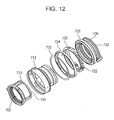
Fig. 12 is a schematic view of an optical apparatus according to an embodiment of the present application. -
Figs. 13A and 13B are a vibration unit according to an embodiment of the present application, used as a dust removing unit. -
Figs. 14A to 14C are schematic views of the piezoelectric element used in a dust removing unit. -
Figs. 15A and 15B are schematic representations illustrating the principle of the vibration of the dust removing unit. -
Fig. 16 is a schematic view of an image sensing apparatus according to an embodiment of the present application. -
Fig. 17 is a schematic view of an image sensing apparatus according to an embodiment of the present application. -
Fig. 18 is a schematic view of an electronic apparatus according to an embodiment of the present application. - Some embodiments of the application will now be described.
- A piezoelectric ceramic according to an embodiment has a remanent polarization and contains a perovskite-type metal oxide containing barium titanate, and Mn. When a surface thereof along the direction of the remanent polarization is subjected to X-ray diffraction analysis at room temperature, the ratio of the diffraction intensity of the (002) plane to the diffraction intensity of the (200) plane (hereinafter referred to as (002)/(200) diffraction intensity ratio) is 1.0 or more, the diffraction peak of the (002) plane has a half width of 1.2° or less, and the lattice constant c of the c-axis thereof and the lattice constant a of the a-axis thereof satisfy the relationship 1.004 ≤ c/a ≤ 1.010.
- In the present embodiment, a lead- and alkali metal-free piezoelectric ceramic having a high mechanical quality factor and exhibiting low power consumption is provided by controlling the crystal structure of a barium titanate-based ceramic.
- The piezoelectric ceramic of the present embodiment contains a perovskite-type metal oxide containing barium titanate, and Mn.
- The perovskite structure of a perovskite-type metal oxide used in the present embodiment refers to that ideally having a cubic system structure as described in Iwanami Dictionary of Physics and Chemistry, 5th edition (in Japanese, Iwanami Shoten Publishers, 1998). Metal oxides having the perovskite structure is generally expressed a formula ABO3. The elements A and B in the perovskite structure are present in the form of ions in the A site and the B site respectively. For example, in the case of a unit cell of a cubic system, element A lies at the vertexes of a cube and element B lies at the center of the cube. Element O lie at the centers of the faces of the cube in the form of negative oxygen ions. The perovskite-type metal oxide containing barium titanate is expressed by the chemical formula BaTiO3. It can be confirmed by crystal structure analysis by, for example, X-ray diffraction or electron diffraction that the piezoelectric ceramic has a perovskite structure. If elements A and B and the oxygen element are each displaced in terms of coordinate from the corresponding positions of the unit cell, the unit cell of the perovskite structure is distorted into, for example, tetragonal, rhombohedral or orthorhombic crystal. From the viewpoint of obtaining a piezoelectric ceramic having a good electromechanical coupling factor, it is advantageous that the perovskite-type metal oxide has a tetragonal crystal structure at room temperature.
- The piezoelectric ceramic of the present embodiment contains Mn. This increases the mechanical quality factor Qm at room temperature. The term mechanical quality factor Qm of a piezoelectric ceramic refers to a coefficient representing the elastic loss by vibration when the piezoelectric ceramic is evaluated as a piezoelectric oscillator. The magnitude of the mechanical quality factor Qm is defined by the sharpness of the resonance curve in impedance measurement. Hence, the mechanical quality factor is a constant representing the sharpness of the resonance of a piezoelectric oscillator. When a piezoelectric element using the piezoelectric ceramic is operated around the resonant frequency, the element is displaced in proportion to the magnitude of the mechanical quality factor Qm.
- The Mn content in terms of metal may be in the range of 0.04 parts by weight to 0.50 parts by weight relative to 100 parts by weight of the perovskite-type metal oxide. In the description herein, the content of an accessory component such as Mn in terms of metal is the proportion of the weight of the accessory component to 100 parts by weight of the metal oxide that is the main constituent of the piezoelectric ceramic, converted from the total weight of the elements constituting the metal oxide measured by X-ray fluorescence analysis (XRF), ICP emission spectroscopy, atomic absorption spectrometry or the like.
- When the Mn content is in the above range, the piezoelectric ceramic can provide satisfactory displacement. If the Mn content is less than 0.04 parts by weight, the mechanical quality factor Qm at room temperature can be reduced to less than 400. A piezoelectric ceramic having a mechanical quality factor Qm of less than 400 at room temperature cannot provide sufficient displacement even around the resonant frequency, and consequently requires a larger input voltage to drive the piezoelectric ceramic. Thus the power consumption (driving electric power) of the piezoelectric ceramic can be increased. On the other hand, if the Mn content is higher than 0.50 parts by weight, the electromechanical coupling factor k31 of the piezoelectric ceramic decreases to increase the input voltage required to drive the piezoelectric ceramic. This can undesirably increase the power consumption. Desirably, the mechanical quality factor Qm is 800 or more. When it is 800 or more, power consumption is not increased. More desirably, the mechanical quality factor Qm is 1200 or more.
- The power consumption used herein refers to the power consumed by the piezoelectric ceramic and is represented by the sum of the power consumed by driving the piezoelectric ceramic and the power consumed in proportion to the capacitance of the piezoelectric ceramic. The power consumed by driving the piezoelectric ceramic is hereinafter referred to as driving electric power, and the power consumed in proportion to the capacitance of the piezoelectric ceramic is referred to as capacitance electric power. The driving electric power of a piezoelectric ceramic tends to decrease when the piezoelectric ceramic has a high electromechanical coupling factor k31 or a high mechanical quality factor Qm. On the other hand, the capacitance electric power tends to decrease when the piezoelectric ceramic has a low relative dielectric constant εr and a high electromechanical coupling factor k31.
- The power consumption of the piezoelectric ceramic of the present embodiment can be measured using electrodes attached thereto with a power meter. The capacitance electric power (CW) is proportional to the product of the capacitance (C) and driving frequency (f) of the piezoelectric ceramic and applied voltage (V), multiplied by 2π. The driving electric power can be determined by subtracting the capacitance electric power from the reading on a power meter.
- The relative dielectric constant εr of the piezoelectric ceramic can be calculated using the capacitance measured with an impedance analyzer or an LCR meter.
- The electromechanical coupling factor k31 and mechanical quality factor Qm of the piezoelectric ceramic can be determined by calculation using the measurements of resonant frequency and anti-resonant frequency measured with an impedance analyzer in accordance with a standard (JEITA EM-4501) of Japan Electronics and Information Technology Industries Association. This method is called resonance-anti-resonance method.
- The piezoelectric ceramic of the present embodiment has a remanent polarization.
- The term remanent polarization refers to the polarization remaining in the piezoelectric ceramic when external electric field is not applied thereto. The spontaneous polarization of a piezoelectric ceramic is oriented in a certain direction by polarizing the piezoelectric ceramic, thereby producing remanent polarization. It can be known whether or not the piezoelectric ceramic has a remanent polarization, by applying a voltage to the piezoelectric ceramic and measuring the relationship between the applied electric field E and the amount P of polarization (P-E hysteresis curve).
- When the surface of the piezoelectric ceramic of the present embodiment along the remanent polarization direction (hereinafter referred to as the measurement surface) is subjected to X-ray diffraction analysis at room temperature, the ratio of the diffraction intensity of the (002) plane to the diffraction intensity of the (200) plane is 1.0 or more. Advantageously, it is 1.06 or more.
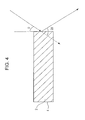
-
Fig. 1 , which is a sectional view of a piezoelectric ceramic according to an embodiment, shows a rectangularpiezoelectric ceramic 8. In the figure, arrow A indicates the remanent polarization direction, and thesurface 4 along the remanent polarization direction of thepiezoelectric ceramic 8 is the measurement surface subjected to X-ray diffraction analysis. The shape of thepiezoelectric ceramic 8 is not limited to rectangular parallelepiped, and may be in circular or polyhedral shape. - The remanent polarization direction can be determined by the following method.
Fig. 2 illustrates the method, in which arrow A designates the remanent polarization direction. First, a polarized piezoelectric ceramic is cut out at an angle β (a multiple of 10, satisfying 0° ≤ β < 360°). The cut surfaces 5 are provided with electrodes thereon, and the piezoelectric constant is measured using the electrodes. This measurement is repeated for different P values for examining the β dependence of the piezoelectric constant. The remanent polarization direction is parallel to an angle (β + 90°) of the sum of 90° and an angle β at which the piezoelectric constant comes to the largest. The β at which the piezoelectric constant comes to the largest may contain an error of ±10° in view of cutting dimension error and measurement error. The use of a d33 meter facilitates the measurement of the piezoelectric constant. - In the piezoelectric ceramic of the present embodiment, when the measurement surface is subjected to X-ray diffraction analysis, the ratio of the diffraction intensity of (002) plane to the diffraction intensity of the (200) plane (hereinafter referred to as the (002)/(200) diffraction intensity ratio) is 1.0 or more. In this measurement, the diffraction intensities of the (002) and (200) planes are the maximum intensities of the diffraction peaks corresponding to the (002) and (200) planes in pseudo-cubic notation, respectively, measured by the 2θ-θ method. The positions of the diffraction peaks of the (002) and (200) planes can be determined by comparing the X-ray diffraction spectrum of the piezoelectric ceramic and known data of barium titanate (for example, ICDD (the International Centre for Diffraction Data, PDF-2 No. 05-0626). In an X-ray diffraction analysis of the measurement surface of a rectangular piezoelectric element prepared by providing the piezoelectric ceramic shown in
Fig. 1 with electrodes on surfaces thereof intersecting the polarization direction, the fact that the (002)/(200) diffraction intensity ratio is 1.0 or more suggests that the piezoelectric ceramic at the measurement surface contains more c-domains than a-domains when observed from the measurement surface. In this state, the piezoelectric ceramic of the present embodiment has a satisfactory mechanical quality factor Qm in a direction perpendicular to the direction of electric field application. Accordingly, the driving electric power of a piezoelectric element using the piezoelectric ceramic of an embodiment of the present application can be reduced by driving the element in a direction perpendicular to the direction of electric field application. On the other hand, if the (002)/(200) diffraction intensity ratio is less than 1.0 when the measurement surface is subjected to X-ray diffraction analysis at room temperature, that is, if the piezoelectric ceramic at the measurement surface contains more a-domains than c-domains when observed from the measurement surface, the mechanical quality factor Qm in a direction perpendicular to the direction of electric field application decreases. The term domain refers to a region in which the direction of spontaneous polarization is aligned. Room temperature is generally is 25°C. In the description herein, however, room temperature refers to temperatures in the range of 20°C to 30°C, in which the piezoelectric ceramic has substantially the same properties and effects as at 25°C. -
Fig. 3 is a schematic view illustrating the a-domain and c-domain of the crystal grains in the piezoelectric ceramic of the present embodiment.Fig. 3 shows the concepts of the a-domain and c-domain of a tetragonal piezoelectric ceramic, wherein arrows B and C designate spontaneous polarization directions. The a-domain refers to a domain in a tetragonal system in which spontaneous polarization is oriented in the [h00] or [0k0] direction and a direction reverse thereto. The c-domain refers to a domain in which spontaneous polarization is oriented in the [001] direction and the direction reverse thereto. The spontaneous polarization in tetragonal barium titanate is oriented in the c-axis. When there are more c-domains than a-domains in observation from an electrode surface, the piezoelectric ceramic of the present embodiment has a satisfactory electromechanical coupling factor k31 as a whole. It is therefore advantageous for the piezoelectric ceramic of the present embodiment that the (002)/(200) diffraction intensity ratio be 1.0 or more when the surface intersecting the remanent polarization direction is subjected to X-ray diffraction analysis at room temperature. - Desirably, the crystal structure of the surface intersecting the remanent polarization direction is estimated by a method not affected by work strain. This is because the piezoelectric ceramic of the present embodiment mainly made of a perovskite-type metal oxide containing barium titanate having a higher Young's modulus than PZT and is accordingly likely to undergo work strain (may be referred to as dislocation) around the surface to be worked, by, for example, polishing, grinding, shaving, or cutting off. It is therefore advantageous to perform finishing by buffing using colloidal silica. Such buffing can lead to a smooth surface having a surface roughness of 200 nm or less. In this operation, the surface worked is desirably removed at a depth of 10 µm or more. The surface roughness can be measured with a stylus surface roughness tester in accordance with JIS B 0651-2001. The surface roughness mentioned herein refers to center line average surface roughness Ra.
- The conditions for X-ray diffraction analysis are not particularly limited, and it may be performed by a 2θ-θ method using a parallel beam, or any other conventional method. X-ray diffraction analysis is typically performed as below.
- A Cu-Kα tube is used as the radiation source. By setting the scattering angle 2θ in the range of 20° to 50°, information of (002) and (200) planes can be obtained. The desired spot diameter of the incident beam depends on the area of the measurement surface, but is desirably such that the entire area of the measurement surface can be irradiated with the incident beam. Also, the scanning speed may be set in the range of 0.10 degree/min to 1.00 degree/min from the viewpoint of ensuring a satisfactory intensity, and the sampling intervals are set in the range of 0.001 degree to 0.020 degree from the viewpoint of obtaining high reproducibility of measurement results.
Fig. 4 is a schematic representation illustrating X-ray diffraction analysis of the piezoelectric ceramic of the present embodiment, showing the relationship between θ and 2θ. If a multi-axis diffractometer is used, the angle Ψ between themeasurement surface 4 and the normal to incident beam is set to 0°. - The ratio of the lattice constant c of the c-axis of the piezoelectric ceramic of the present embodiment at room temperature to the lattice constant a of the a-axis thereof satisfy the relationship 1.004 ≤ c/a ≤ 1.010 (c > a). When the c/a ratio is in this range, the piezoelectric ceramic has a satisfactory electromechanical coupling factor k31. Accordingly, the driving electric power of a piezoelectric element using the piezoelectric ceramic of the present embodiment can be reduced. On the other hand, if the c/a ratio is less than 1.004, the crystal structure of the piezoelectric element comes close to a cubic system, so that the electromechanical coupling factor k31 decreases at room temperature. Consequently, the input voltage required to drive the piezoelectric element increases; hence the driving electric power increases undesirably. Also, if the c/a ratio is larger than 1.010, the voltage required for polarization increases undesirably.
- The lattice constants a and c of the piezoelectric ceramic can be determined using the plane intervals obtained from diffraction peaks observed by the 2θ-θ method. The interval d(200) of (200) planes, the interval d(002) of (002) planes are expressed by the following equations, and also the lattice constants a and c are expressed by the following equations, wherein θ200 and θ002 represent the angles at which the diffraction peaks of the (200) plane and (002) plane are maximum, respectively. These crystal planes are represented by pseudo cubic notation.


- From the viewpoint of obtaining a satisfactory electromechanical coupling factor k31, it is advantageous that the piezoelectric ceramic has a tetragonal crystal structure at room temperature.
- In the present embodiment, the diffraction peak of the (002) plane of the measurement surface of the piezoelectric ceramic may have a half-width of 1.2° or less at room temperature. Advantageously, it is 0.5° or less. The term half-width refers to the difference between the angles θ1 and θ2 (θ2 > θ1) at which the peak intensity is half (P/2) of the maximum peak intensity P on the diffraction peak curve. Half-width may be referred to as full width at half maximum. For calculating the magnitude of maximum intensity, the diffraction intensity based on the background must be subtracted.
- If the diffraction peak of the (002) plane has a half-width of 1.2° or less at room temperature, the piezoelectric ceramic has a satisfactory mechanical quality factor Qm. On the other hand, if the half-width of the diffraction peak of the (002) plane is larger than 1.2°, the ceramic cannot have crystallinity sufficient to exhibit good mechanical quality factor Qm.
- The piezoelectric ceramic of the present embodiment may further contain Bi. The presence of Bi in the piezoelectric ceramic increases the relative density of the ceramic. The Bi content may be in the range of 0.04 parts by weight to 0.80 parts by weight relative to 100 parts by weight of the perovskite-type metal oxide.
- If the Bi content is less than 0.04 parts by weight, the relative density of the piezoelectric ceramic is unlikely to increase in comparison with ceramic not containing Bi. On the other hand, if the Bi content is higher than 0.80 parts by weight, the electromechanical coupling factor k31 decreases to increase the input voltage required to drive the piezoelectric ceramic. This can undesirably increase the driving electric power.
- The perovskite-type metal oxide of the piezoelectric ceramic of the present embodiment may be expressed by the following general formula (1):

- In general formula (1), x represents a numeral satisfying 0.125 ≤ x ≤ 0.300, y represents a numeral satisfying 0.041 ≤ y ≤ 0.074, and q represents a numeral satisfying 0.986 ≤ q ≤ 1.020.
- When x, y and q are in those ranges, the piezoelectric ceramic exhibits a higher mechanical quality factor Qm and a satisfactory electromechanical coupling factor k31 at room temperature.
- General formula (1) of the perovskite-type metal oxide represents that Ba and Ca are present in the A site, while Ti and Zr are present in the B site. Part of Ba or Ca, however, may be present in the B site. Similarly, part of Ti or Zr may be present in the A site. In general formula (1), the mole ratio of the elements in the B site to the oxygen (O) element is 1 to 3. Even if this ratio is slightly varied, the metal oxide is within the scope of the application as long as the main phase of the metal oxide has the perovskite structure.
- In the present embodiment, the molar fraction x of the Ca in the A site of the piezoelectric ceramic desirably satisfies 0.125 ≤ x ≤ 0.300. If x is less than 0.125, the relative dielectric constant εr at room temperature can be increased to increase the capacitance electric power. In contrast, if x is larger than 0.300, the mechanical quality factor Qm decreases to increase the input voltage required to drive the piezoelectric ceramic. This can undesirably increase the driving electric power. More desirably, x satisfies 0.125 ≤ x ≤ 0.190.
- In the present embodiment, the molar fraction y of the Zr in the B site of the piezoelectric ceramic may satisfy 0.041 ≤ y ≤ 0.074. If y is larger than 0.074, the relative dielectric constant εr at room temperature increases. This can undesirably increase the capacitance electric power. In contrast, if y is less than 0.041, the electromechanical coupling factor k31 decreases to increase the input voltage required to drive the piezoelectric ceramic. This can undesirably increase the driving electric power. More desirably, y satisfies 0.050 ≤ y ≤ 0.074.
- In the piezoelectric ceramic of the present embodiment, the ratio q of the moles of Ba and Ca in the A site to the moles of Ti and Zr in the B site desirably satisfies 0.986 ≤ q ≤ 1.020. If q is less than 0.986, the crystal grains of the piezoelectric ceramic can grow abnormally and result in reduced mechanical strength. In contrast, if q is larger than 1.020, the temperature required to grow crystal grains increases excessively. This can make it difficult to sinter the ceramic in an ordinary furnace. "Make it difficult to sinter" implies that the resulting ceramic has pores or defects therein or does not have a sufficient density. Desirably, q satisfies 0.998 ≤ q ≤ 1.016. The ratio of the total moles A1 of Ba and Ca to the total moles B1 of Ti, Zr and Mn may satisfy 0.993 ≤ A1/B1 ≤ 0.998. When the ratio A1/B1 is in this range, the piezoelectric ceramic of the present embodiment exhibits satisfactory electromechanical coupling factor k31 and mechanical quality factor. This implies that the piezoelectric element can be driven with a low power consumption.
- Desirably, the electromechanical coupling factor k31 of the piezoelectric ceramic is 0.200 or more at room temperature.
- When the electromechanical coupling factor k31 is 0.200 or more at room temperature, the input power required to drive the piezoelectric element can be reduced to reduce the driving electric power. In contrast, if the electromechanical coupling factor k31 is less than 0.200, the input voltage required to drive the piezoelectric ceramic can increase. This increases the driving electric power.
- Desirably, the relative dielectric constant εr of the piezoelectric ceramic is 2500 or less at room temperature. If the relative dielectric constant exceeds 2500, the capacitance electric power of the piezoelectric element can increase.
- In the present embodiment, the crystal grains of the piezoelectric ceramic may have an average equivalent circular diameter in the range of 0.5 µm to 10 µm. The term average equivalent circular diameter refers to the average of the equivalent circular diameters of a plurality of crystal grains. When the average equivalent circular diameter of the crystal grains is in this range, the piezoelectric ceramic can exhibit satisfactory mechanical quality factor and mechanical strength. If the average equivalent circular diameter is less than 0.5 µm, the piezoelectric properties of the piezoelectric ceramic can be poor. In contrast, if it is larger than 10 µm, the mechanical strength can decrease undesirably. Advantageously, the average equivalent circular diameter is in the range of 1.9 µm to 9.0 µm.
- The term "equivalent circular diameter" used herein refers to "projected area-equivalent circular diameter", which is the diameter of a circle with an area equivalent to the projected area of a grain when measured through a microscope. In the present embodiment, the equivalent circular diameter may be measured by any method without particular limitation. For the measurement, for example, the surface of the piezoelectric ceramic may be photographed through a polarizing microscope or an electron microscope, and the image of the photograph is processed. An optical microscope and an electron microscope may be selectively used depending on the grain size.
- In the present embodiment, the relative density of the piezoelectric ceramic may be in the range of 93% to 100%. The relative density is the ratio of the measured density of a piezoelectric ceramic to the theoretical density calculated using the lattice constant of the piezoelectric ceramic and the atomic weights of the elements in the ceramic. The lattice constant can be estimated by, for example, X-ray diffraction analysis. Density can be measured by, for example, Archimedian method.
- A relative density of less than 93% can lead to an unsatisfactory electromechanical coupling factor k31 or mechanical quality factor Qm, or a reduced mechanical strength. Desirably, the relative density of the piezoelectric ceramic is in the range of 95% to 100%, more desirably in the range of 97% to 100%.
- A method for manufacturing the piezoelectric ceramic will now be described, but is not limited to the disclosed method. The method for manufacturing the piezoelectric ceramic includes the steps of forming a compact from raw materials, and sintering the compact.
- The step of forming a compact from raw materials is not particularly limited. For example, the compact may be formed using solid powders of oxides, carbonates, nitrates, oxalates or the like containing the constituent elements. Then the compact may be sintered by a conventional method under normal pressure. The raw materials include metal compounds such as a Ba compound, a Ca compound, a Ti compound, a Zr compound, a Mn compound, and a Bi compound.
- Ba compounds used as the raw material include barium oxide, barium carbonate, barium oxalate, barium acetate, barium nitrate, barium titanate, barium zirconate, and barium titanate zirconate.
- Ca compounds used as the raw material include calcium oxide, calcium carbonate, calcium oxalate, calcium acetate, calcium titanate, and calcium zirconate.
- Ti compounds used as the raw material include titanium oxide, barium titanate, barium titanate zirconate, and calcium titanate.
- Zr compounds used as the raw material include zirconium oxide, barium zirconate, barium titanate zirconate, and calcium zirconate.
- Mn compounds used as the raw material include manganese carbonate, manganese dioxide, manganese acetate, and trimanganese tetraoxide.
- An exemplary Bi compound may be bismuth oxide.
- The material added to control the ratio q of the moles of Ba and Ca in the A site to the moles of Ti and Zr in the B site is not particularly limited. Any compound of Ba compounds, Ca compounds, Ti compounds and Zr compounds can produce the same effect.
- The compact is a solid material formed by compacting solid powders. For compacting the powders, uniaxial pressing, cold isostatic pressing, hot isostatic processing, casting, or extrusion may be applied. For forming the compact, granulated powder is advantageously used. When a compact of granulated powder is sintered, the sintered compact tends to have a uniform grain size.
- Although the granulation of the raw material powders is not particularly limited, a spray dry process is advantageous for forming granulated powder having a uniform particle size.
- A binder, such as polyvinyl alcohol (PVA), polyvinyl butyral (PVB), or acrylic resin, may be used for granulation. The binder may be added in a proportion of 1 part by weight to 10 parts by weight relative to 100 parts by weight of the raw material powders. From the viewpoint of increasing the density of the compact, the proportion of the binder may be in in the range of 2 parts by weight to 5 parts by weight.
- The compact may be sintered in any process without particular limitation. For example, the compact may be sintered in an electric furnace or a gas furnace, or by being energized for heating, using microwaves or millimeter waves, hot isostatic press (HIP), or any other technique. Sintering in an electric furnace or a gas furnace may be performed in a continuous or batch furnace.
- The sintering is desirably performed at, but not limited to, a temperature at which compounds react to sufficiently grow crystals. For example, the sintering temperature may be in the range of 1100°C to 1400°C, such as 1100°C to 1350°C, from the viewpoint of controlling the grain size in the range of 1.5 µm to 10 µm. In order to stabilize the properties of the sintered piezoelectric material with high repeatability, the sintering is performed at a constant temperature in the above range for 2 to 48 hours. In addition, it is advantageous to rapidly cool the compact when it is cooled from the maximum temperature. Rapid cooling helps internal stress remain in the piezoelectric ceramic. Consequently, a larger number of c-domains are observed at the measurement surface in the piezoelectric ceramic. Accordingly, the mechanical quality factor increases. The cooling rate may be 50°C/hour or more.
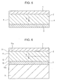
- A piezoelectric element according to an embodiment includes a
first electrode 1, apiezoelectric material portion 2, and asecond electrode 3. Thepiezoelectric material portion 2 is made of the piezoelectric ceramic of an embodiment of the present application. The first and the second electrode intersect the remanent polarization direction of the piezoelectric ceramic.Fig. 5 , which is a sectional view of the piezoelectric element of the present embodiment, shows the structure of the piezoelectric element including a rectangularpiezoelectric material portion 2 provided with a first and a secondrectangular electrode first electrode 1 and thesecond electrode 3 are disposed on opposing surfaces of thepiezoelectric material portion 2. The shape of thepiezoelectric material portion 2 is not limited to rectangular parallelepiped, and may be in circular or polyhedral shape. The shape and arrangement of the first andsecond electrodes - When the
first electrode 1 and thesecond electrode 3 intersect the remanent polarization direction of the piezoelectric ceramic, the piezoelectric element has a satisfactory electromechanical coupling factor k31 and mechanical quality factor Qm in a direction perpendicular to the direction of voltage application. The first andsecond electrodes second electrodes first electrode 1 and thesecond electrode 3 may be made of different materials from each other. From the viewpoint of mass production and cost efficiency, it is advantageous that the electrodes be made of Ag. Ag electrodes may have a thickness of 1 µm to 10 µm. - The method for forming the first and
second electrodes second electrodes piezoelectric material portion 2, and the piezoelectric ceramic and the Ag paste are baked by being heated at one time at temperatures up to a maximum temperature of 700°C to 900°C for about 5 minutes. Still more advantageously, after being baked, the composite of the electrodes and the piezoelectric ceramic is cooled at a rate of 100°C/hour or more. By baking the Ag paste under such conditions, the Ag electrodes exhibit satisfactory, stable conductivity. In addition, this baking applies heat treatment to the dielectric ceramic of thepiezoelectric material portion 2 to release residual stress. Consequently, the (002)/(200) diffraction intensity ratio of the surface intersecting the remanent polarization direction can be easily controlled to 1.0 or more. It is however not undesirable to heat-treat the piezoelectric ceramic at 1000°C or more. Such heat treatment can vary the composition of the piezoelectric ceramic. - Polarization of the piezoelectric ceramic may be performed by any technique without particular limitation. For example, polarization may be performed in the air or in silicone oil. From the viewpoint of mass production, polarization in the air is advantageous. Advantageously, the polarization is performed by applying an electric field of 5 kV/cm to 14 kV/cm for about 10 minutes to 30 minutes at temperatures up to a maximum temperature of 90°C to 150°C. Also, while the ceramic is being cooled from the maximum temperature, it is advantageous to keep applying the electric field. By keeping applying the electric field, the (002)/(200) diffraction intensity ratio of the surface intersecting the remanent polarization direction can be easily controlled to 1.0 or more. Desirably, the piezoelectric ceramic has been heat-treated at a temperature of 700°C to 900°C from the viewpoint of reducing the electric field applied for polarization. The piezoelectric ceramic subjected to such heat treatment can be easily polarized even at an electric field of 8 kV/cm or less. From the viewpoint of increasing the mechanical quality factor Qm, the cooling may be performed at a rate of 100°C/h or more.
-
Fig. 6 is a schematic view of a vibration device according to an embodiment of the present application. - The vibration device includes the piezoelectric element and a
diaphragm 9 on which the piezoelectric element is disposed. When the surface of thepiezoelectric material portion 2 closer to thediaphragm 9 is the bottom surface thereof and the surface of thepiezoelectric material portion 2 opposite the bottom surface is the front surface, the (002)/(200) diffraction intensity ratio A of themeasurement surface 4 at the bottom surface (at a position 10) and the (002)/(200) diffraction intensity ratio B of themeasurement surface 4 at the front surface (at a position 11) satisfy the relationship A > B at room temperature. - The
diaphragm 9 is made of an elastic material. The elastic material may be, but is not limited to, stainless steel such as SUS or invar, Si, ceramic, glass, or quartz. Theposition 10 of the measurement surface at the bottom surface of thepiezoelectric material portion 2 is an arbitrary point lying in the region of themeasurement surface 4 from thebottom surface 10a of the piezoelectric material portion 2 (piezoelectric ceramic) to themidpoint 12 of themeasurement surface 4. Theposition 11 of the measurement surface at the front surface of thepiezoelectric material portion 2 is an arbitrary point lying in the region of themeasurement surface 4 from thefront surface 11a of the piezoelectric material portion 2 (piezoelectric ceramic) to themidpoint 12 of themeasurement surface 4. Theposition 10 of themeasurement surface 4 is desirably in the region of 50% in length from thebottom surface 10a relative to the length from thebottom surface 10a to themidpoint 12, more desirably in the region of 20% in length from the bottom surface. Similarly, theposition 11 of themeasurement surface 4 is desirably in the region of 50% in length from thefront surface 11a relative to the length from thefront surface 11a to themidpoint 12, more desirably in the region of 20% in length from thefront surface 11a. - When the above-described diffraction intensity ratio is larger than the diffraction intensity ratio B, the vibration device exhibits a satisfactory mechanical quality factor Qm. This is probably because the piezoelectric ceramic bonded to the diaphragm receives a tensile stress from the diaphragm. For measuring the (002)/(200) diffraction intensity ratio A of
position 10 at the bottom surface of thepiezoelectric material portion 2, the spot diameter of incident beam is set so that the measurement surface from the midpoint to the front surface is not irradiated with X-ray radiation. For measuring the (002)/(200) diffraction intensity ratio B ofposition 11 at the front surface of thepiezoelectric material portion 2, the spot diameter of incident beam is set so that the measurement surface from the midpoint to the bottom surface is not irradiated with X-ray radiation. In the present embodiment, the spot diameter is desirably 100 µm or less. Since the measurement of diffraction intensity requires high accuracy, the same region is measured at least 10 times, and the average of the measurements is used for calculating the diffraction intensity ratio. - Desirably, the thermal expansion coefficient α1 at room temperature of the piezoelectric ceramic of the
piezoelectric material portion 2 and the thermal expansion coefficient α2 of thediaphragm 9 at room temperature satisfy the relationship α1 < α2. When this relationship holds true, the piezoelectric ceramic receives a tensile stress from the diaphragm, so that c-domains tend to increase in number when observed from the measurement surface. Consequently, the mechanical quality factor Qm of the vibration device increases further. The increase in the mechanical quality factor Qm of the vibration device increases an efficiency of a device including the vibration device. This efficiency refers to the ratio of output power to input power. Hence, when input power is constant, the magnitude of power consumption is an indicator of the efficiency. In an ultrasonic motor that will be described later, the efficiency refers to the ratio of the product of torque and rotation speed to input power. - The thermal expansion coefficient of the piezoelectric ceramic used in the present embodiment is desirably 7 × 10⁻⁶ K-1 to 8 × 10⁻⁶ K-1 at room temperature. The thermal expansion coefficient of the
diaphragm 9 is desirably higher than 8 × 10⁻⁶ K-1. Accordingly, for a stainless steel diaphragm, SUS, particularly SUS 420, is advantageously used as the material. - The vibration device may be produced by any process without particular limitation. A polarized piezoelectric element may be bonded to a diaphragm, or a piezoelectric element previously bonded to a diaphragm may be polarized. In view of productivity, it is advantageous to bond a polarized piezoelectric element to a diaphragm. The number of steps can be reduced.
- Since the piezoelectric ceramic of the present embodiment mainly contains barium titanate, the piezoelectric property thereof can be lost by being heated at a temperature of 130°C or more. Accordingly, an adhesive capable of adhering at 100°C or less is desirably used for bonding the piezoelectric element.
- A liquid ejecting head according to an embodiment will now be described.
- A liquid ejecting head according to an embodiment of the application includes a liquid chamber including a vibration portion provided with the above-described piezoelectric element, and a portion defining an ejection opening communicating with the liquid chamber. A liquid ejecting head according to another embodiment includes a liquid chamber including a vibration portion provided with the above-described vibration device, and a portion defining an ejection opening communicating with the liquid chamber.
-
Figs. 7A and 7B are schematic views of a liquid ejecting head according to an embodiment. As shown inFigs. 7A and 7B , the liquid ejecting head includespiezoelectric elements 101. Each of thepiezoelectric elements 101 includes afirst electrode 1011, a piezoelectricceramic portion 1012 made of a piezoelectric ceramic, and asecond electrode 1013. The piezoelectricceramic portion 1012 is formed in a pattern as needed, as shown inFig. 7B . -
Fig. 7B schematically shows the liquid ejecting head. The liquid ejecting head hasejection openings 105, discreteliquid chambers 102, communication holes 106 communicating between the discreteliquid chambers 102 and thecorresponding ejection openings 105,liquid chamber partitions 104, acommon liquid chamber 107, adiaphragm 103, and thepiezoelectric elements 101. Although the shape of thepiezoelectric element 101 shown inFig. 7B is rectangular, thepiezoelectric element 101 may have any shape, such as oval, circle or parallelogram. In general, the piezoelectricceramic portion 1012 has a shape corresponding to the shape of the discreteliquid chamber 102. - The
piezoelectric element 101 and vicinity thereof of the liquid ejecting head will now be described with reference toFig. 7A. Fig. 7A is a sectional view of the piezoelectric element shown inFig. 7B taken in the width direction thereof. Although thepiezoelectric element 101 shown inFig. 7A has a rectangular section, the section may be of trapezoid or inverted trapezoid. - In
Fig. 7A , thefirst electrode 1011 is the lower electrode, and thesecond electrode 1013 is the upper electrode. However, the arrangement of the first andsecond electrodes first electrode 1011 may be used as the lower electrode or the upper electrode. Similarly, thesecond electrode 1013 may be used as the upper electrode or the lower electrode. Abuffer layer 108 may be provided between thediaphragm 103 and the lower electrode. These components are named depending on the manufacturing process of the device. The piezoelectric element produces the same effect irrespective of what the components are called. - The
diaphragm 103 is vertically displaced by the expansion and contraction of the piezoelectricceramic portion 1012, thereby applying a pressure to a liquid in the corresponding discreteliquid chamber 102. Consequently, the liquid is ejected through theejection opening 105. The liquid ejecting head of the present embodiment can be used in a printer or for manufacturing electronic devices. - The
diaphragm 103 has a thickness in the range of 1.0 µm to 15 µm, such as in the range of 1.5 µm to 8 µm. Thediaphragm 103 may be made of any material, and may be made of Si from the viewpoint of workability. The Si of thediaphragm 103 may be doped with boron or phosphorus. The buffer layer or electrode on thediaphragm 103 may act as a part of thediaphragm 103. Thebuffer layer 108 has a thickness in the range of 5 nm to 300 nm, such as in the range of 10 nm to 200 nm. Theejection opening 105 has an equivalent circle diameter in the range of 5 µm to 40 µm. The shape of the ejection opening 105 may be circular, star-like or triangular. - A liquid ejecting apparatus according to an embodiment will now be described. A liquid ejecting apparatus according to an embodiment of the present application includes a portion on which a transfer medium is placed, and the above-described liquid ejecting head.
- The liquid ejecting apparatus may be an ink jet recording apparatus as shown in
Figs. 8 and9. Fig. 9 shows the liquid ejecting apparatus (ink jet recording apparatus) 881 shown inFig. 8 in a state where theexternal members 882 to 885 and 887 are removed therefrom. The inkjet recording apparatus 881 includes anautomatic feeding section 897 that feeds recording paper, which is a transfer medium, into thebody 896 thereof. The inkjet recording apparatus 881 further includes three sections that guide the recording paper fed from theautomatic feeding section 897 to a predetermined recording position and then to anejection port 898 from the recording position. More specifically, the ink jet recording apparatus has the following three sections: a conveyingsection 899 on which the transfer medium is placed; arecording section 891 where recording is performed on the recording paper conveyed to the recording position; and a recoveringsection 890 that recovers therecording section 891. Therecording section 891 contains a liquid ejecting head of an embodiment of the application, and is provided therein with acarriage 892 that reciprocally moves on a rail. - In this ink jet recording apparatus, the
carriage 892 is moved on the rail according to electrical signals transmitted from a computer, and the piezoelectric ceramic portion is displaced by applying a driving voltage to the electrodes between which the piezoelectric ceramic portion is disposed. The displacement of the piezoelectric ceramic portion applies a pressure to the discreteliquid chamber 102 via thediaphragm 103 shown inFig. 7B , thereby ejecting the ink through the ejection opening 105 for printing. - The liquid ejecting apparatus of the present embodiment can evenly eject liquid at high speed and can be downsized.
- Although the present embodiment illustrates a printer, the liquid ejecting apparatus may be used as a facsimile or multifunctional machine, a copy machine or any other ink jet recording apparatus, or an industrial liquid ejecting apparatus.
- Also, the user can select a transfer medium suitable for use. The liquid ejecting apparatus may have the structure in which the liquid ejecting head moves relative to a transfer medium on a stage.
- An ultrasonic motor of an embodiment of the present application will now be described. An ultrasonic motor according to an embodiment includes a vibration device, and a moving device in contact with the vibration device. Desirably, the vibration device is that of an embodiment of the present application.
-
Fig. 10 is a schematic view of an ultrasonic motor according to an embodiment of the present application. The ultrasonic motor includes a piezoelectric element including a single-layer piezoelectric material portion made of a piezoelectric ceramic. The ultrasonic motor includes anoscillator 201, arotor 202 in contact with a sliding surface of theoscillator 201 with a pressure applied by a pressure spring (not shown), and anoutput shaft 203 integrated with therotor 202. Theoscillator 201 includes a metalelastic ring 2011, apiezoelectric element 2012 according to an embodiment of the present application, and an organic adhesive 2013 (for example, epoxy or cyanoacrylate adhesive) bonding thepiezoelectric element 2012 to theelastic ring 2011. Thepiezoelectric element 2012 includes a first and a second electrode (not shown) and a piezoelectric material portion made of a piezoelectric ceramic between the first and second electrodes. InFig. 10 , theoscillator 201 acts as the vibration device, and therotor 202 acts as the moving device. - When a two-phase alternating voltage having phases different by an odd multiple of π/2 is applied to the piezoelectric element, the
oscillator 201 generates flexural traveling waves, and each point on the sliding surface of theoscillator 201 moves elliptically. If therotor 202 is in contact with the sliding surface of theoscillator 201 with pressure applied, therotor 202 is rotated in the direction opposite to the direction of the flexural traveling waves by receiving a frictional force from theoscillator 201. A driven body (not shown) joined to theoutput shaft 203 is driven by the rotation of therotor 202. - When a voltage is applied to the piezoelectric ceramic of the piezoelectric material portion, the piezoelectric ceramic is expanded and contracted by the piezoelectric effect. If the piezoelectric material portion is in contact with a metal or any other elastic material, the elastic material is bent by the expansion and contraction of the piezoelectric ceramic. The ultrasonic motor of the present embodiment is based on this principle.
- The ultrasonic motor of the present embodiment, which includes the above-described vibration device, can operate more efficiently.
- An optical apparatus according to an embodiment will now be described. The optical apparatus includes a driving portion provided with the above-described ultrasonic motor.
-
Figs. 11A and 11B show sectional views of the main portion of an interchangeable lens barrel of a single-lens reflex camera as an exemplary optical apparatus.Fig. 12 shows an exploded perspective view of the interchangeable lens barrel of the single-lens reflex camera as an exemplary optical apparatus. A fixingbarrel 712, alinear guide barrel 713 and a frontgroup lens barrel 714 are fixed to amount 711 at which the lens barrel is attached to or removed from the camera. These are fixing members for the interchangeable lens barrel. - The
linear guide barrel 713 has alinear guide groove 713a for linearly guiding afocus lens 702 in an optical axis direction.Cam rollers axis screw 718 to a reargroup lens barrel 716 holding thefocus lens 702. Thecom roller 717a is fitted in thelinear guide groove 713a. - A
cam ring 715 is rotatably fitted on the inner periphery of thelinear guide barrel 713. The relative movement of thelinear guide barrel 713 and thecam ring 715 in the optical axis direction is restricted by fitting aroller 719 fixed to thecam ring 715 in aperipheral groove 713b of thelinear guide barrel 713. Thecam ring 715 is provided with acam groove 715a therein for thefocus lens 702. Thecam roller 717b is also fitted in thecam groove 715a. - A
rotation transmitting ring 720 is disposed at the outer periphery of the fixingbarrel 712. Therotation transmitting ring 720 is held with aball race 727 for rotation at a fixed position relative to the fixingbarrel 712. Therotation transmitting ring 720 rotatably holdsrollers 722 onaxes 720f radially extending from therotation transmitting ring 720. Theportion 722a of eachroller 722 having the larger diameter is in contact with theend 724b, in the direction of the mount, of a manual focusing ring 724 (hereinafter thisend 724b is referred to as mount-side end). Theportion 722b of the roller 22 having the smaller diameter is in contact with a bindingmember 729. Sixrollers 722 are arranged at regular intervals on the outer periphery of therotation transmitting ring 720, each in the same manner as described above. - A low friction sheet (washer member) 733 is disposed on the inner diameter portion of the manual focusing
ring 724. The low friction sheet is pinched between the mount-side end 712a of the fixingbarrel 712 and thefront end 724a of the manual focusingring 724. The outer diameter surface of thelow friction sheet 733 is in a shape of ring and is fitted on theinner surface 724c defining the inner diameter of the manual focusingring 724. Also, theinner surface 724c of the manual focusingring 724 is fitted on theouter diameter portion 712b of the fixingbarrel 712. Thelow friction sheet 733 serves to reduce the friction of the rotation ring mechanism for rotating the manual focusingring 724 on the optical axis relative to the fixingbarrel 712. - The
larger diameter portion 722a of theroller 722 and the mount-side end 724b of the manual focusingring 724 are in contact with each other with a pressure applied by the force of awave washer 726 pressing anultrasonic motor 725 in a forward direction of the lens. Similarly, thesmaller diameter portion 722b of theroller 722 and the bindingmember 729 are in contact with each other with an appropriate pressure applied by the force of thewave washer 726 pressing theultrasonic motor 725 in a forward direction of the lens. The movement of thewave washer 726 toward the mount is restricted by awasher 732 bayonet-coupled to the fixingbarrel 712. The spring force (urging force) generated by thewave washer 726 is transmitted to theultrasonic motor 725 and further to theroller 722, and presses the manual focusingring 724 on the mount-side end 712a of the fixingbarrel 712. Hence, the manual focusingring 724 is incorporated in a state where it is pressed on the mount-side end 712a of the fixingbarrel 712 with thelow friction sheet 733 therebetween. - When the
ultrasonic motor 725 is driven for rotation relative to the fixingbarrel 712 by a controller (not shown), theroller 722 is rotated on theaxis 720f because of the frictional contact between the bindingmember 729 and thesmaller diameter portion 722b of theroller 722. The rotation of theroller 722 on theaxis 720f causes therotation transmitting ring 720 to rotate on the optical axis (autofocusing operation). - If a force for rotation on the optical axis is applied to the manual focusing
ring 724 from a manual operation input portion (not shown), the following operation occurs. Since the mount-side end 724b of the manual focusingring 724 is in pressure contact with thelarger diameter portion 722a of theroller 722, theroller 722 is rotated on theaxis 720f by friction. The rotation of thelarger diameter portion 722a of theroller 722 on theaxis 720f causes therotation transmitting ring 720 to rotate on the optical axis. At this time, the friction retaining force of therotor 725c and thestator 725b prevents theultrasonic motor 725 from rotating (manual focusing operation). - Two
focus keys 728 are attached to therotation transmitting ring 720 so as to oppose each other, and are fitted in anotch 715b formed in an end of acam ring 715. Thus the rotation of therotation transmitting ring 720 on the optical axis by autofocusing operation or manual focusing operation is transmitted to thecam ring 715 with thefocus keys 728 therebetween. When the cam ring is rotated on the optical axis, the reargroup lens barrel 716 whose rotation is restricted by thecam roller 717a and thelinear guide groove 713a is reciprocally moved along thecam groove 715a in thecam ring 715 by thecam roller 717b. Thus, thefocus lens 702 is driven for focusing. - Although the present embodiment has illustrated an interchangeable lens barrel of a single-lens reflex camera as an optical apparatus, the optical apparatus may be a compact camera, an electronic still camera, and any other camera including an ultrasonic motor in the driving section.
- Vibration units for delivering and removing particles, powder, or liquid are widely used in electronic apparatuses. A dust removing unit including the piezoelectric element according to an embodiment of the present application will now be described as an exemplary vibration unit.
- A vibration unit according to an embodiment of the present application includes a vibration device including the above-described piezoelectric element and a diaphragm on which the piezoelectric element is disposed, and functions to remove dust on the surface of the diaphragm. Desirably, the vibration device is that of an embodiment of the present application. A dust removing unit according to an embodiment of the present application includes a vibrating portion provided with the above-described vibration unit.
-
Figs. 13A and 13B are schematic views of a dust removing unit according to an embodiment of the present application. Thedust removing unit 310 includes platelikepiezoelectric elements 330 and adiaphragm 320. Thediaphragm 320 may be made of any material without particular limitation. For example, if thedust removing unit 310 is used for optical devices, an optically transparent material or an optically reflective material is used in thediaphragm 320, and dust is removed from the portion of the optically transparent material or optically reflective material. -
Figs. 14A to 14C are schematic views of thepiezoelectric element 330 shown inFigs. 13A and 13B .Figs. 14A and 14C show the front and the rear of thepiezoelectric element 330, andFig. 14B shows a side of thepiezoelectric element 330. As shown inFigs. 13A and 13B , thepiezoelectric element 330 includes apiezoelectric material portion 331 made of a piezoelectric ceramic, afirst electrode 332 and asecond electrode 333. Thefirst electrode 332 and thesecond electrode 333 oppose the plate surface of thepiezoelectric material portion 331. The surface of thepiezoelectric element 330 provided with thefirst electrode 332 viewed inFig. 14C is referred to as afirst electrode surface 336. The surface of thepiezoelectric element 330 provided with thesecond electrode 333 viewed inFig. 14A is referred to as asecond electrode surface 337. - The electrode surfaces are each the surface of the piezoelectric element provided with an electrode. For example, as shown in
Figs. 14A to 14C , thefirst electrode 332 may round and extend to the second electrode surface. - The
piezoelectric elements 330 are fixed to thediaphragm 320 in such a manner that the first electrode surfaces 336 of thepiezoelectric elements 330 are bonded to a plate surface of thediaphragm 320, as shown inFigs. 13A and 13B . When thepiezoelectric element 330 operates, a stress occurs between thepiezoelectric element 330 and thediaphragm 320, and thediaphragm 320 generates out-of-plane vibration. In thedust removing unit 310 of the present embodiment, dust on the surface of thediaphragm 320 is removed by the out-of-plane vibration of thediaphragm 320. The term out-of-plane vibration refers to an elastic vibration that displaces the diaphragm in the direction of the optical axis, that is, in the thickness direction of the diaphragm. -
Figs. 15A and 15B are schematic representations illustrating the principle of the vibration of thedust removing unit 310.Fig. 15A shows a state where out-of-plane vibration is generated in thediaphragm 320 by applying an in-phase alternating electric field to a pair ofpiezoelectric elements 330 opposing in a side-to-side direction. The piezoelectric ceramic of eachpiezoelectric element 330 is polarized in the same direction as the thickness direction of thepiezoelectric element 330, and thedust removing unit 310 is operated in a seventh-order vibration mode.Fig. 15B shows a state where out-of-plane vibration is generated in thediaphragm 320 by applying a reverse phase alternating electric field with a phase difference of 180° to the pair ofpiezoelectric elements 330. In this instance, thedust removing unit 310 operates in a sixth-order vibration mode. By operating thedust removing unit 310 in at least two vibration modes depending on cases, dust on the surface of the diaphragm can be removed effectively. - An image sensing apparatus according to an embodiment will now be described. The image sensing apparatus includes an image sensing element unit having a light receiving face, and the above-described dust removing unit on the light receiving face of the image sensing element unit.
Figs. 16 and17 show a digital single-lens reflex camera as an exemplary image sensing apparatus according to an embodiment of the present application. -
Fig. 16 is a front perspective view of thebody 601 of the camera viewed from the object, showing a state where the photographing lens unit is removed.Fig. 17 is an exploded perspective view of the general structure of the camera, for illustrating the structure around the dust removing unit and theimage sensing apparatus 400. - The
camera body 601 shown inFig. 16 is provided therein with amirror box 605 to which a photographing light beam having passed through the photographing lens is guided. Themirror box 605 contains a main mirror (quick return mirror) 606. Themain mirror 606 can take a position kept at an angle of 45° with respect to the photographing optical axis so as to conduct the photographing light beam to a penta roof mirror (not shown), and a position retracted from the photographing light beam so as to conduct the light beam to an image sensing element (not shown). - In the embodiment shown in
Fig. 17 , the camera body includes achassis 300 acting as the frame of the camera body, and the chassis is provided with themirror box 605 and ashutter unit 200 in that order from the direction of the object toward thechassis 300. Also, animage sensing unit 400 is disposed at the photographer side of thechassis 300. Theimage sensing unit 400 includes the diaphragm of a dust removing unit and an image sensing element unit. The diaphragm of the dust removing unit is coaxially aligned with the light receiving face of the image sensing element unit. Theimage sensing unit 400 is to be set on the mounting face of the mounting portion 602 (Fig. 16 ) with respect to which the photographing lens unit is mounted, and is adjusted so that the image sensing face of the image sensing element unit becomes parallel to the photographing lens unit with a predetermined distance therebetween. - A digital single-lens reflex camera has been described as the image sensing apparatus of an embodiment of the present application, the image sensing apparatus may be a photographing lens-interchangeable camera such as a mirrorless digital single-lens reflex camera not including a
mirror box 605. The image sensing apparatus of the present embodiment may be applied to image sensing apparatuses such as photographing lens unit-interchangeable video cameras, copy machines, facsimiles, and scanners, and electronic apparatuses including such an image sensing apparatus and required to remove dust from the surface of the optical component. - An electronic apparatus according to an embodiment will now be described. An electronic apparatus of the present embodiment includes a piezoelectric acoustic component including the above-described piezoelectric element. Examples of the piezoelectric acoustic component include a loud-speaker, a beeper, a microphone, and a surface acoustic wave (SAW) element.
-
Fig. 18 shows a perspective view of a digital camera as an exemplary electronic apparatus, viewed from in front of thebody 931. Thebody 931 is provided with anoptical device 901, amicrophone 914, an electronicflash emitting portion 909 and anauxiliary light portion 916 at the front face thereof. Themicrophone 914 is embedded in the body, being indicated by a dashed line. Themicrophone 914 has a hole in front thereof for picking up sounds from the outside. - The
body 931 is also provided with apower button 933, aloudspeaker 912, azoom lever 932, and arelease button 908 for focusing operation on the upper face thereof. Theloudspeaker 912 is embedded in thebody 931, being indicated by a dashed line. A hole is formed in front of theloudspeaker 912 and through which sounds are transmitted to the outside. - The piezoelectric acoustic component of an embodiment is used in at least one of a
microphone 914, aloudspeaker 912, or a surface acoustic wave element. - Although a digital camera has been described as an exemplary embodiment of the electronic apparatus of the present application, the electronic apparatus may be any electronic apparatus including a piezoelectric acoustic component, such as a sound reproduction apparatus; a sound recorder, a cellular phone, or an information terminal.
- As described above, the piezoelectric element according to an embodiment of the present application is suitable for liquid ejecting heads, liquid ejecting apparatuses, ultrasonic motors, optical apparatuses, vibration units, dust removing units, image sensing apparatuses, and electronic apparatuses.
- The use of the piezoelectric element and vibration device according to an embodiment of the present application can provide a liquid ejecting head that can exhibit a power consumption lower than or equal to that of liquid ejecting heads including a lead-containing piezoelectric element, and an efficiency, a nozzle density and an ejection speed, each higher than or equal to those of liquid ejecting heads including a lead-containing piezoelectric element.
- Also, the use of the liquid ejecting head according to an embodiment of the present application can provide a liquid ejecting apparatus that can exhibit a power consumption lower than or equal to that of liquid ejecting apparatuses including a lead-containing piezoelectric element, and an efficiency, a nozzle density and an ejection speed, each higher than or equal to those of liquid ejecting apparatuses including a lead-containing piezoelectric element.
- The use of the piezoelectric element and vibration device according to an embodiment of the present application can provide an ultrasonic motor that can exhibit a power consumption lower than or equal to that in the case of using a lead-containing piezoelectric element, and an efficiency, a driving force and a durability, each higher than or equal to those in the case of using a lead-containing piezoelectric element.
- Also, the use of the ultrasonic motor according to an embodiment of the present application can provide an optical apparatus that can exhibit a power consumption lower than or equal to that in the case of using a lead-containing piezoelectric element, and an efficiency, a durability and operation accuracy, each higher than or equal to those in the case of using a lead-containing piezoelectric element.
- The use of the piezoelectric element and vibration device according to an embodiment of the present application can provide an ultrasonic motor that can exhibit a power consumption lower than or equal to that in the case of using a lead-containing piezoelectric element, and an efficiency, a vibrating ability and a durability, each higher than or equal to those in the case of using a lead-containing piezoelectric element.
- The use of the vibration unit according to an embodiment of the present application provides a dust removing unit that can exhibit a power consumption lower than or equal to that in the case of using a lead-containing piezoelectric element, and an efficiency, a dust-removing ability and a durability, each higher than or equal to those in the case of using a lead-containing piezoelectric element.
- The use of the dust removing unit according to an embodiment of the present application provides an image sensing apparatus that can exhibit a power consumption lower than or equal to that in the case of using a lead-containing piezoelectric element, and an efficiency and a dust-removing ability, each higher than or equal to those in the case of using a lead-containing piezoelectric element.
- Also, the use of a piezoelectric acoustic component including a piezoelectric element of an embodiment of the present application can provide an electronic apparatus that can exhibit a power consumption lower than or equal to that in the case of using a lead-containing piezoelectric element, and an efficiency and a sound generation, each higher than or equal to those in the case of using a lead-containing piezoelectric element.
- The piezoelectric element and vibration device of an embodiment of the present application can be used in devices as described above, and, in addition, in piezoelectric actuators such as ultrasonic oscillators.
- The piezoelectric ceramic of the disclosed embodiment will be further described with reference to the following Examples. However, the invention is not limited to the Examples.
-

- Raw material powders for the composition (Ba0.84Ca0.16)1.006 (Ti0.94Zr0.06)O3, which is a composition of general formula (1) (Ba1-xCax)q(Ti1-yZry)O3 in which x = 0.16, y = 0.06 and q = 1.006, were weighed out as below.
- A perovskite-type metal oxide powder containing barium titanate, having a particle size of 300 nm produced by a solid phase process, and calcium titanate powder, calcium zirconate powder and barium carbonate powder were weighed so as to satisfy the molar fractions of the above chemical formula.
- Relative to 100 parts by weight of the metal oxide expressed by (Ba0.84Ca0.16)1.006 (Ti0.94Zr0.06)O3, trimanganese tetraoxide was weight in a proportion of 0.24 parts by weight in terms of Mn. All the powders weighed out were mixed in a dry manner in a ball mill for 24 hours. A PVA binder in a proportion of 3 parts by weight to the total weight of the mixture of the powders was applied to the surfaces of the powder for granulation, using a spray dryer.
- The granulated powder was compacted into a disk-shaped compact with a press forming machine at a pressure of 200 MPa.
- The compact was placed in an electric furnace in an air atmosphere. The furnace was first heated to 600°C and held at this temperature for 3 hours. Then, the compact was further heated up to a maximum temperature of 1340°C and held for 5 hours, followed by cooking to 300°C from 1340°C at a rate of 100°C/h, thereby yielding a piezoelectric ceramic.
- The resulting ceramic was subjected to measurements for the average equivalent circular diameter of the crystal grains and the relative density of the ceramic. The average equivalent circular diameter was 5.7 µm, and the relative density was 96.2%. For the observation of the crystal grains, a polarizing microscope was used. The photographic image taken through the polarizing microscope was processed for calculating the average equivalent circular diameter. For estimating the relative density, Archimedian method was used.
- Subsequently, the composition of the ceramic was estimated by X-ray fluorescence analysis and ICP emission spectroscopy. It was thus found that the ceramic contained 0.24 parts by weight of Mn relative to 100 parts by weight of the metal oxide mainly containing barium titanate expressed by the chemical formula:
(Ba0.84Ca0.16)1.006 (Ti0.94Zr0.06)O3. This implies that the composition of the sintered ceramic corresponds to the proportions of the constituents weighed out. The contents of elements other than Ba, Ca, Ti, Zr and Mn were less than 0.001 parts by weight, lower than the detection limit. Formation of Electrodes - The resulting ceramic was polished to a thickness of 0.5 mm, and then an Ag paste was applied to both sides of the ceramic and baked to form 3 µm thick electrodes. For baking, the Ag paste was heated to 800°C at a rate of 5°C/min and held at 800°C for 5 minutes. Then, the temperature was reduced to 40°C at a cooling rate of 350°C/h, and the ceramic with the electrodes was taken out from the electric furnace.
- The resulting ceramic with the electrodes was cut into a strip of 10 mm × 2.5 mm × 0.5 mm in dimensions. The strip of the ceramic with the electrodes was placed on a hot plate heated to 140°C, and an electric field of 0.6 kV/mm was applied between the electrodes on both sides of the ceramic for 30 minutes. Then, the hot plate was cooled at a rate of 200°C/h. After the hot plate was cooled to 40°C, voltage application was stopped. Thus a piezoelectric element including a portion of a piezoelectric ceramic was completed.
- For estimating the remanent polarization of the resulting piezoelectric ceramic, the strip of the polarized piezoelectric element was cut out at an angle β (0°≤ β < 360°) as shown in
Fig. 2 . A first and a second Au electrode were formed by sputtering on the polarized ceramic, and the piezoelectric constant was measured with a d33 meter. When P = 180°, the piezoelectric constant was the highest. This result shows that the remanent polarization direction of the piezoelectric ceramic of the piezoelectric element was perpendicular to the surfaces of the Ag electrodes. - Subsequently, the crystal structure of the piezoelectric ceramic of the strip-shaped piezoelectric element was estimated. For the estimation, the measurement surface (of 2.5 mm × 0.5 mm in dimensions) of the piezoelectric element along the remanent polarization direction was irradiated with X-ray radiation. The surface was measured with XRD (D8 ADVANCE manufactured by Bruker AXS) by the 2θ-θ method. More specifically, a Cu-Kα tube was used as the radiation source, and 2θ was set in the range of 20° to 50°. The scanning speed was set at 0.50°/min, and sampling was performed at intervals of 0.02°. The spot diameter of incident beam was 50 µm. The (002)/(200) diffraction intensity ratio of the measurement surface was 1.46; c/a was 1.007; the half-width of the (002) diffraction peak of the measurement surface was 0.36°. The room temperature at this time was 25°C.
- Furthermore, the crystal structure of the surface (of 10 mm × 2.5 mm in dimensions) of the piezoelectric ceramic intersecting the remanent polarization direction was estimated. First, the Ag electrodes were polished with an abrasive of #2000 in grit size to remove the Ag electrodes. The polished surfaces were buffed with colloidal silica. The crystal structure of the surface of the polished ceramic intersecting the remanent polarization direction was estimated under the same conditions as the crystal structure of the measurement surface. The (002)/(200) diffraction intensity ratio of the surface intersecting the remanent polarization direction was 1.21. The room temperature at this time was 25°C.
- The strip-shaped piezoelectric element was measured for relative dielectric constant εr, electromechanical coupling factor k31 and mechanical quality factor Qm with an impedance analyzer. The room temperature at this time was 25°C. The impedance analyzer was set to an application voltage of 0.05 Vpp. The relative dielectric constant εr was 1780; the electromechanical coupling factor k31 was 0.219; and the mechanical quality factor Qm was 1700. For measuring the electromechanical coupling factor k31 and the mechanical quality factor Qm, a resonance-anti-resonance method was applied.
- The power consumption of the strip-shaped piezoelectric element was measured. The power consumption was measured with a power meter when an alternating voltage applied to the piezoelectric element was adjusted by varying the magnitude and frequency of the voltage so that the displacement of the piezoelectric element could be 1.0 µm. The displacement was measured with a laser Doppler vibrometer. The power consumption was 16 mW.
- Ceramics of Examples 2 to 10 were prepared in the same manner as in Example 1, except that bismuth oxide was used as the raw material powder. The proportions of the constituents weighed out were as shown in Table 1. In Table 1, A1/B1 represents the ratio of the sum (A1) of the moles of Ba and Ca to the sum (B1) of the moles of Ti, Zr and Mn. Then, the average equivalent circular diameter and the relative density were estimated in the same manner as in Example 1. The results are shown in the Table 2. As a result of composition analysis performed in the same manner as in Example 1, the composition of the sintered ceramic corresponds to the proportions of the constituents weighed out in any sample.
- Subsequently, piezoelectric elements were prepared in the same manner as in Example 1, and the remanent polarization direction, crystal structure, relative dielectric constant εr, electromechanical coupling factor k31, mechanical quality factor Qm and power consumption of the piezoelectric ceramic of the piezoelectric element were measured. The room temperature at this time was 25°C. The results are shown in Tables 3 and 4.
- Raw material powders for the composition (Ba0.90Ca0.10)1.000TiO3, which is a composition of the general formula (Ba1-xCax)q(Ti1-yZry)O3 in which x = 0.10, y = 0 and q = 1.000, were weighed out as below.
- Calcium carbonate powder, barium carbonate powder, titanium oxide powder, and manganese carbonate powder, each having a purity of 99.9% were weighed so as to satisfy the molar fractions of the above chemical formula.
- Relative to 100 parts by weight of the metal oxide expressed by (Ba0.90Ca0.10)1.00TiO3, manganese carbonate was weight in a proportion of 0.24 parts by weight in terms of Mn. All the powders weighed out were mixed in a wet manner in a ball mill for 16 hours. The resulting mixture was calcined at 1000°C for 2 hours. After the calcined powder was pulverized for 8 hours in a wet process, 3 parts by weight of PVA binder relative to the calcined powder was applied to attach the binder to the surfaces of the powder for granulation, using a spray dryer.
- The granulated powder was compacted into a disk-shaped compact with a press forming machine at a pressure of 200 MPa.
- The compact was sintered in an air atmosphere in an electric furnace over a period of 48 hours in total, including being held at temperatures up to a maximum temperature of 1300°C for 10 hours, thus yielding the ceramic of Comparative Example 1. For cooling the compact, the furnace was cooled from the maximum temperature.
- The resulting ceramic was subjected to measurements for the average equivalent circular diameter of the crystal grains and the relative density of the ceramic. The average equivalent circular diameter was 12.5 µm, and the relative density was 92.0%. For the observation of the crystal grains, a polarizing microscope was used. The photographic image taken through the polarizing microscope was processed for calculating the average equivalent circular diameter. For estimating the relative density, Archimedian method was used.
- Subsequently, the composition of the ceramic was estimated by X-ray fluorescence analysis and ICP emission spectroscopy. It was thus found that the ceramic contained 0.24 parts by weight of Mn relative to 100 parts by weight of the metal oxide expressed by the chemical formula:
(Ba0.90Ca0.10)1.000TiO3. This implies that the composition of the sintered ceramic corresponds to the proportions of the constituents weighed out. The contents of elements other than Ba, Ca, Ti and Mn were less than 0.001 parts by weight, lower than the detection limit. - The resulting ceramic was polished to a thickness of 0.5 mm, and then an Ag paste was applied to both sides of the ceramic and baked to form 3 µm thick electrodes. For baking, the Ag paste was heated to 600°C at a rate of 5°C/min and held at 600°C for 2 minutes. The heating was then stopped. Then, the temperature was reduced to 40°C at a cooling rate of 50°C/h, and the ceramic was taken out from the electric furnace.
- The resulting ceramic with the electrodes was cut into a strip of 10 mm × 2.5 mm × 0.5 mm in dimensions. The strip-shaped ceramic with the electrodes was placed in a silicone oil bath heated to 70°C, and an electric field of 1.0 kV/mm was applied between the electrodes on both sides of the ceramic for 30 minutes. Then, after the ceramic was cooled at a rate of 50°C/h, voltage application was stopped. Thus a piezoelectric element including a portion of the piezoelectric ceramic of Comparative Example 1 was completed.
- For estimating the remanent polarization of the resulting piezoelectric ceramic, the strip-shaped polarized piezoelectric element was cut out at an angle β (0° ≤ β < 360°) as shown in
Fig. 2 . A first and a second Au electrode were formed by sputtering on the polarized ceramic, and the piezoelectric constant was measured with a d33 meter. When β = 180°, the piezoelectric constant was the highest. This result shows that the remanent polarization direction of the piezoelectric ceramic of the piezoelectric element was perpendicular to the surfaces of the Ag electrodes. - Subsequently, the crystal structure of the piezoelectric ceramic of the strip-shaped piezoelectric element was estimated. For the estimation, the measurement surface (of 2.5 mm × 0.5 mm in dimensions) of the piezoelectric element along the remanent polarization direction was irradiated with X-ray radiation. The surface was measured with XRD (D8 ADVANCE manufactured by Bruker AXS) by the 2θ-θ method. More specifically, a Cu-Kα tube was used as the radiation source, and 2θ was set in the range of 20° to 50°. The scanning speed was set at 0.50°/min, and sampling was performed at intervals of 0.02°. The spot diameter of incident beam was 50 µm. The (002)/(200) diffraction intensity ratio of the measurement surface was 0.91; c/a was 1.009; the half-width of the (002) diffraction peak of the measurement surface was 0.38°. The room temperature at this time was 25°C.
- Furthermore, the crystal structure of the surface (of 10 mm × 2.5 mm in dimensions) of the piezoelectric ceramic intersecting the remanent polarization direction was estimated. First, the Ag electrodes were polished with an abrasive of #2000 in grit size to remove the Ag electrodes. The polished surfaces were buffed with colloidal silica. The crystal structure of the surface of the polished ceramic intersecting the remanent polarization direction was estimated under the same conditions as the crystal structure of the measurement surface. The room temperature at this time was 25°C. The (002)/(200) diffraction intensity ratio of the surface intersecting the remanent polarization direction was 0.91.
- The strip-shaped piezoelectric element was measured for relative dielectric constant εr, electromechanical coupling factor k31 and mechanical quality factor Qm by an impedance analyzer. The room temperature at this time was 25°C. The impedance analyzer was set to an application voltage of 0.05 Vpp. The relative dielectric constant εr was 880; the electromechanical coupling factor k31 was 0.119; and the mechanical quality factor Qm was 1700. For measuring the electromechanical coupling factor k31 and the mechanical quality factor Qm, a resonance-anti-resonance method was applied.
- The power consumption of the strip-shaped piezoelectric element was measured. The power consumption was measured with a power meter when an alternating voltage applied to the piezoelectric element was adjusted by varying the magnitude and frequency of the voltage so that the displacement of the piezoelectric element could be 1.0 µm. The displacement was measured with a laser Doppler vibrometer. The power consumption was 35 mW.
- To a perovskite-type metal oxide powder of 100 nm in particle size containing barium titanate produced by hydrothermal synthesis, 3 parts by weight of PVA binder was applied to attach the binder to the surfaces of the barium titanate powder for granulation, using a spray dryer.
- The granulated powder was compacted into a disk-shaped compact with a press forming machine at a pressure of 200 MPa.
- The compact was sintered to yield a ceramic in an electric furnace using the profile of first being heating to 1390°C at a rate of 15°C/min, held at 1390°C for 1 minute, cooled to 1190°C at a rate of 30°C/min, held at 1190°C for 4 hours, and further cooling to room temperature at a rate of 60°C/h.
- The resulting ceramic was subjected to measurements for the average equivalent circular diameter of the crystal grains and the relative density of the ceramic. The average equivalent circular diameter was 8.1 µm, and the relative density was 94.9%. For the observation of the crystal grains, a polarizing microscope was used. The photographic image taken through the polarizing microscope was processed for calculating the average equivalent circular diameter. For estimating the relative density, Archimedian method was used.
- Subsequently, the composition of the ceramic was estimated by X-ray fluorescence analysis and ICP emission spectroscopy. As a result, it was found that the ceramic was expressed by the chemical formula Ba1.000TiO3. This implies that the composition of the sintered ceramic corresponds to the proportions of the constituents weighed out. The contents of elements other than Ba and Ti were less than 0.001 parts by weight, lower than the detection limit.
- The resulting ceramic was polished to a thickness of 0.5 mm, and then 400 nm thick gold electrodes were formed on both sides of the ceramic sheet by DC sputtering. In this instance, 30 nm thick adhesion layers were formed of titanium between the electrodes and the ceramic. The adhesion layers were formed without being heated. Also, the resulting gold electrodes were not heat-treated after being formed.
- The resulting ceramic with the electrodes was cut into a strip of 10 mm × 2.5 mm × 0.5 mm in dimensions. The strip of the ceramic with the electrodes was placed on a hot plate heated to 100°C, and an electric field of 1.0 kV/mm was applied between the electrodes on both sides of the ceramic for 30 minutes. Then, after the ceramic was cooled at a rate of 50°C/h, voltage application was stopped. Thus a piezoelectric element including a portion of the piezoelectric ceramic of Comparative Example 2 was completed.
- The remanent polarization direction of the resulting piezoelectric ceramic was estimated in the same manner as in Comparative Example 1. When β = 180°, the piezoelectric constant was the highest. This result shows that the remanent polarization direction of the piezoelectric ceramic of the piezoelectric element was perpendicular to the surfaces of the Au electrodes. Estimation of Crystal Structure
- Subsequently, the crystal structure of the piezoelectric ceramic of the strip-shaped piezoelectric element of Comparative Example 2 was estimated in the same manner as in Comparative Example 1. The room temperature at this time was 25°C. The (002)/(200) diffraction intensity ratio of the measurement surface was 0.97; c/a was 1.009; the half-width of the (002) diffraction peak of the measurement surface was 0.13°. The (002)/(200) diffraction intensity ratio of the surface intersecting the remanent polarization direction was 0.96.
- Subsequently, the relative dielectric constant εr, the electromechanical coupling factor k31, the mechanical quality factor Qm and the power consumption were measured in the same manner as in Comparative Example 1. The room temperature at this time was 25°C. The relative dielectric constant εr was 3650; the electromechanical coupling factor k31 was 0.188; the mechanical quality factor Qm was 280; and the power consumption was 72 mW.
- A compact was formed for producing a ceramic in the same manner as in Examples 1 to 10. The proportions of the constituents weighed out were as shown in Table 1.
- The compact was sintered in an air atmosphere in an electric furnace over a period of 24 hours in total, including being held at temperatures up to a maximum temperature of 1440°C for 5 hours, thus yielding a ceramic. For cooling the compact, the furnace was cooled from the maximum temperature.
- The resulting ceramic was subjected to measurements for the average equivalent circular diameter and the relative density in the same manner as in Comparative Example 2. The results are shown in the Table 2.
- Subsequently, the composition of the ceramic was estimated by X-ray fluorescence analysis and ICP emission spectroscopy. It was thus found that the ceramic contained 0.40 parts by weight of Mn relative to 100 parts by weight of the metal oxide expressed by the chemical formula: (Ba0.84Ca0.16)1.014 (Ti0.90Zr0.10)O3. This implies that the composition of the sintered ceramic corresponds to the proportions of the constituents weighed out. The contents of elements other than Ba, Ca, Ti, Zr and Mn were less than 0.001 parts by weight, lower than the detection limit.
- The resulting ceramic was polished to a thickness of 0.5 mm, and then 400 nm thick gold electrodes were formed on both sides of the ceramic sheet by DC sputtering. In this instance, 30 nm thick adhesion layers were formed of titanium between the electrodes and the ceramic. The adhesion layers were formed without being heated. Also, the resulting gold electrodes were not heat-treated after being formed.
- The resulting ceramic with the electrodes was cut into a strip of 10 mm × 2.5 mm × 0.5 mm in dimensions. The strip of the ceramic with the electrodes was placed on a hot plate heated to 100°C, and an electric field of 1.0 kV/mm was applied between the electrodes on both sides of the ceramic for 30 minutes. Then, after the ceramic was cooled at a rate of 50°C/h, voltage application was stopped. Thus a piezoelectric element including a portion of the piezoelectric ceramic of Comparative Example 3 was completed.
- The remanent polarization direction of the resulting piezoelectric ceramic was estimated in the same manner as in Comparative Example 1. When β = 180°, the piezoelectric constant was the highest. This result shows that the remanent polarization direction of the piezoelectric ceramic of the piezoelectric element was perpendicular to the surfaces of the Au electrodes. Estimation of Crystal Structure
- Subsequently, the crystal structure of the piezoelectric ceramic of the strip-shaped piezoelectric element of Comparative Example 3 was estimated in the same manner as in Comparative Example 1. The room temperature at this time was 25°C. The (002)/(200) diffraction intensity ratio of the measurement surface was 1.19; c/a was 1.001; the half-width of the (002) diffraction peak of the measurement surface was 0.45°. The (002)/(200) diffraction intensity ratio of the surface intersecting the remanent polarization direction was 1.09.
- Subsequently, the relative dielectric constant εr, the electromechanical coupling factor k31, the mechanical quality factor Qm and the power consumption were measured in the same manner as in Comparative Example 1. The room temperature at this time was 25°C. The relative dielectric constant εr was 2520; the electromechanical coupling factor k31 was 0.188; the mechanical quality factor Qm was 1810; and the power consumption was 31 mW.
Table 1 x y q Mn (parts by weight) Bi (parts by weight) A1/B1 Example 1 0.160 0.060 1.006 0.24 0.00 0.997 Example 2 0.140 0.070 1.002 0.16 0.03 0.996 Example 3 0.125 0.060 0.998 0.04 0.28 0.996 Example 4 0.140 0.074 1.012 0.36 0.44 0.997 Example 5 0.300 0.045 1.002 0.12 0.00 0.998 Example 6 0.180 0.041 1.004 0.14 0.60 0.998 Example 7 0.160 0.060 1.016 0.50 0.15 0.996 Example 8 0.160 0.060 1.003 0.12 0.80 0.998 Example 9 0.000 0.000 1.002 0.10 0.00 0.998 Example 10 0.100 0.000 1.000 0.24 0.00 0.990 Comparative Example 1 0.100 0.000 1.000 0.24 0.00 0.990 Comparative Example 2 0.000 0.000 1.000 0.00 0.00 1.000 Comparative Example 3 0.160 0.100 1.016 0.40 0.00 1.000 Table 2 Relative density (%) Average grain size (µm) Example 1 96.2 5.7 Example 2 95.8 6.4 Example 3 93.1 1.9 Example 4 94.8 2.7 Example 5 93.5 4.1 Example 6 93.2 8.2 Example 7 96.1 2.9 Example 8 94.8 3.7 Example 9 95.9 8.7 Example 10 92.0 12.1 Comparative Example 1 92.0 12.5 Comparative Example 2 94.9 8.1 Comparative Example 3 92.1 7.3 Table 3 (002)/(200) Diffraction intensity ratio of measurement surface c/a of measurement surface (002) Half-width (°) of measurement surface (002)/(200) Diffraction intensity ratio of surface intersecting remanent polarization direction Remanent polarization direction k31@25°C εr@25°C Qm@25°C Example 1 1.46 1.007 0.36 1.21 Perpendicular to electrodes 0.219 1780 1700 Example 2 1.52 1.004 0.47 1.31 Perpendicular to electrodes 0.248 2080 1520 Example 3 1.43 1.006 0.33 1.24 Perpendicular to electrodes 0.229 1850 490 Example 4 1.42 1.005 0.31 1.26 Perpendicular to electrodes 0.245 2060 1810 Example 5 1.37 1.008 0.33 1.16 Perpendicular to electrodes 0.214 1380 830 Example 6 1.31 1.009 0.28 1.14 Perpendicular to electrodes 0.211 1460 860 Example 7 1.24 1.007 0.26 1.03 Perpendicular to electrodes 0.202 1600 2170 Example 8 1.42 1.007 0.25 1.25 Perpendicular to electrodes 0.244 1750 1320 Example 9 1.18 1.010 0.33 1.08 Perpendicular to electrodes 0.201 2400 1620 Example 10 1.06 1.009 0.34 1.04 Perpendicular to electrodes 0.131 920 2480 Comparative Example 1 0.91 1.009 0.38 0.91 Perpendicular to electrodes 0.119 880 1700 Comparative Example 2 0.93 1.009 0.13 0.96 Perpendicular to electrodes 0.188 3650 280 Comparative Example 3 1.19 1.001 0.45 1.09 Perpendicular to electrodes 0.188 2520 1810 Table 4 Power consumption (mW) Example 1 16 Example 2 12 Example 3 21 Example 4 12 Example 5 21 Example 6 22 Example 7 16 Example 8 14 Example 9 25 Example 10 25 Comparative Example 1 35 Comparative Example 2 72 Comparative Example 3 31 - The results shown in Tables 1 to 4 will now be discussed. In comparison of electromechanical coupling factors k31 among Examples 1 to 9 and Comparative Examples 1 to 3, the electromechanical coupling factors k31 of the Examples are 0.201 or less. Accordingly, these Examples exhibited power consumptions of 25 mW or less, lower than the Comparative Examples.
- In comparison among Examples 1 to 9, the power consumptions of Examples 1, 2, 4, 7, 8 and 9 were as low as 25 mW or less. This is probably because the mechanical quality factors Qm of these Examples were 1320 or more and higher than the other Examples.
- In comparison between Example 10 and Comparative Example 1, the power consumption of Example 10 was lower than that of Comparative Example 1. Although the piezoelectric ceramics of Example 10 and Comparative Example 1 have the same composition, the (002)/(200) diffraction intensity ratio of the measurement surface was different from each other, and that of Comparative Example 1 was less than 1.0. Accordingly, the electromechanical coupling factor k31 and the mechanical quality factor Qm were also different. In Comparative Example 1, since the electromechanical coupling factor k31 was lower than that of Example 10, the voltage required for a displacement of 1.0 µm was increased. Accordingly, the capacitance electric power increases to increase the power consumption.
- In Comparative Example 2 as well, the (002)/(200) diffraction intensity ratio at the measurement surface was less than 1.0, and accordingly the electromechanical coupling factor k31 came to less than 0.200. Also, Comparative Example 2 exhibited a power consumption of 72 mW, larger than Comparative Example 1. This is probably because in Comparative Example 2, the mechanical quality factor was much lower than that of Comparative Example 1 and, accordingly, the driving electric power was increased to increase the power consumption.
- Comparative Example 3 exhibited a c/a of less than 1.004. Also, Comparative Example 3 exhibited a power consumption of 31 mW larger than Examples 1 to 10. This is probably because the high relative dielectric constant of Comparative Example 3 increased the capacitance electric power thereof.
- A piezoelectric element was prepared by forming electrodes on the piezoelectric ceramic (thermal expansion coefficient: 8 × 10⁻⁶ K-1) of Example 1 and polarizing the ceramic, in the same manner as in Example 1. An invar diaphragm (thermal expansion coefficient: 1 × 10⁻⁶ K-1) of 10 mm × 2.5 mm × 2.5 mm in dimensions was bonded to the resulting piezoelectric element in a shape of strip of 10 mm × 2.5 mm × 0.5 mm in dimensions with an adhesive curable at room temperature. Thus a vibration device shown in
Fig. 6 was prepared. - Subsequently, the crystal structure of the piezoelectric ceramic of the resulting vibration device was estimated. For the estimation, the measurement surface (of 2.5 mm × 0.5 mm in dimensions) of the piezoelectric ceramic was measured at two points at the front surface and the bottom surface. The surface was measured with XRD (D8 ADVANCE manufactured by Bruker AXS) by the 2θ-θ method. More specifically, a Cu-Kα tube was used as the radiation source, and 2θ was set in the range of 20° to 50°. The scanning speed was set at 0.50°/min, and sampling was performed at intervals of 0.02°. The spot diameter of incident beam was 50 µm. The measurement was repeated 10 times, and measured (002)/(200) diffraction intensity ratios were averaged for estimation. The (002)/(200) diffraction intensity ratio B at the front surface was 1.37, and the (002)/(200) diffraction intensity ratio A at the bottom surface was 1.41. The room temperature at this time was 25°C.
- The mechanical quality factor Qm of the vibration device, which was measured by a resonance-anti-resonance method, was 2200. Furthermore, the voltage at which the vibration speed could be 0.5 m/s was measured by applying an alternating voltage having a frequency around the resonance frequency. As a result, a voltage of 14 Vpp was used until reaching 0.5 m/s.
- A piezoelectric element was prepared by forming electrodes on the piezoelectric ceramic (thermal expansion coefficient: 8 × 10⁻⁶ K-1) of Example 1 and polarizing the ceramic, in the same manner as in Example 1. A SUS 420 diaphragm (thermal expansion coefficient: 9 × 10⁻⁶ K-1) of 10 mm × 2.5 mm × 2.5 mm in dimensions was bonded to the resulting piezoelectric element in a shape of strip of 10 mm × 2.5 mm × 0.5 mm in dimensions with an adhesive curable at room temperature to yield a vibration device shown in
Fig. 6 . - Subsequently, the crystal structure of the piezoelectric ceramic of the resulting vibration device was estimated in the same manner as in Example 11. The (002)/(200) diffraction intensity ratio B at the front surface was 1.37, and the (002)/(200) diffraction intensity ratio A at the bottom surface was 1.43. The room temperature at this time was 25°C.
- The mechanical quality factor Qm of the vibration device, which was measured by a resonance-anti-resonance method, was 2300.
- Furthermore, the voltage at which the vibration speed could be 0.5 m/s was measured by applying an alternating voltage having a frequency around the resonance frequency to the vibration device. As a result, a voltage of 12.5 Vpp was used until reaching 0.5 m/s.
- A piezoelectric element was prepared by forming electrodes on the piezoelectric ceramic (thermal expansion coefficient: 7.8 × 10⁻⁶ K-1) of Comparative Example 2 and polarizing the ceramic, in the same manner as in Example 1. A SUS 420 diaphragm (thermal expansion coefficient: 9 × 10⁻⁶ K-1) of 10 mm × 2.5 mm × 2.5 mm in dimensions was bonded to the resulting piezoelectric element in a shape of strip of 10 mm × 2.5 mm × 0.5 mm in dimensions with an adhesive curable at room temperature to yield a vibration device shown in
Fig. 6 . - Furthermore, the voltage at which the vibration speed could be 0.5 m/s was measured by applying an alternating voltage having a frequency around the resonance frequency to the vibration device. Although voltages up to 20 Vpp were applied, the vibration speed did not reach 0.5 m/s.
- In comparison between Examples 11 and 12, the vibration speed of the vibration device using the SUS 420 diaphragm reached 0.5 m/s at lower voltage. Probably, this results from the difference in mechanical quality factor Qm between the vibration devices. This suggests that when the thermal expansion coefficient of the diaphragm is higher than that of the piezoelectric ceramic, the vibration device exhibits high driving efficiency.
- A liquid ejecting head having the structure shown in
Fig. 7B was prepared using the piezoelectric ceramic of Example 1. The liquid ejecting head ejected ink according to the electrical signal input. - A liquid ejecting head having the structure shown in
Fig. 7B was prepared using the piezoelectric ceramic of Comparative Example 3. The liquid ejecting head ejected ink according to the electrical signal input. The power consumption at this time was twice that of Example 13. Preparation and Evaluation of Liquid Ejecting Apparatus - A liquid ejecting apparatus having the structure shown in
Fig. 8 was prepared using the liquid ejecting head of Example 13. The liquid ejecting apparatus ejected ink on a recording medium according to the electrical signal input - A liquid ejecting apparatus having the structure shown in
Fig. 8 was prepared using the liquid ejecting head of Comparative Example 5. The liquid ejecting apparatus ejected ink on a recording medium according to the electrical signal input. The power consumption at this time was twice that of Example 14. - An ultrasonic motor having the structure shown in
Fig. 10 was prepared using the vibration device of the same material as in Example 11. The input voltage was controlled by applying a load of 150 g·cm so that the rotational speed could come to 100 rpm, and the efficiency at this time was measured. As a result, the efficiency was 11.1%. - An ultrasonic motor having the structure shown in
Fig. 10 was prepared using the vibration device of the same material as in Example 12. The input voltage was controlled by applying a load of 150 g·cm so that the rotational speed could come to 100 rpm, and the efficiency at this time was measured. As a result, the efficiency was 12.7%. - An ultrasonic motor having the structure shown in
Fig. 10 was prepared using the vibration device of the same material as in Comparative Example 4. For setting the rotational speed to 100 ppm, the input voltage was controlled by applying a load of 150 g·cm. The rotational speed however did not reach 100 rpm. - In comparison between Examples 15 and 16, the ultrasonic motor using the SUS 420 vibration device exhibited higher efficiency. Probably, this results from the difference in mechanical quality factor Qm between the vibration devices. This suggests that when the thermal expansion coefficient of the diaphragm is higher than that of the piezoelectric ceramic, the ultrasonic motor exhibits high driving efficiency.
- An optical apparatus having the structure shown in
Fig. 11 was prepared using the ultrasonic motor of Example 16. The optical apparatus exhibited autofocus operation according to the alternating voltage applied. - An optical apparatus having the structure shown in
Fig. 11 was prepared using the ultrasonic motor of Comparative Example 7. The optical apparatus exhibited autofocus operation according to the alternating voltage applied. The power consumption at this time was 2.5 times that of Example 17. - A dust removing unit having the structure shown in
Fig. 13 was prepared using the piezoelectric ceramic of Example 1. Plastic beads were scattered and an alternating voltage was applied. The dust removing unit exhibited good dust removal. - A dust removing unit having the structure shown in
Fig. 13 was prepared using the piezoelectric ceramic of Comparative Example 3. Plastic beads were scattered and an alternating voltage was applied to remove dust. The power consumption at this time was twice that of Example 18. Preparation and Evaluation of Image Sensing Apparatus - An image sensing apparatus having the structure shown in
Fig. 16 was prepared using the dust removing unit of Example 18. When the image sensing apparatus was operated, the dust on the surface of the image sensing unit was satisfactorily removed and images without defects resulting from dust were formed. - An image sensing apparatus having the structure shown in
Fig. 16 was prepared using the dust removing unit of Comparative Example 9. When the image sensing apparatus was operated, the dust on the surface of the image sensing unit was satisfactorily removed and images without defects resulting from dust were formed. The power consumption at this time was however twice that of Example 19. Preparation and Evaluation of Electronic Apparatus - An electronic apparatus having the structure shown in
Fig. 18 was prepared using the piezoelectric ceramic of Example 1. The electronic apparatus performed loudspeaking operation according to the alternating voltage applied. - An electronic apparatus having the structure shown in
Fig. 18 was prepared using the piezoelectric ceramic of Comparative Example 3. The electronic apparatus performed loudspeaking operation according to the alternating voltage applied. The power consumption at this time was twice that of Example 20. - The piezoelectric ceramic of an embodiment of the present application has a high mechanical quality factor, and accordingly piezoelectric elements using the piezoelectric ceramic can operate with low power consumption and high efficiency. In addition, the piezoelectric ceramic does not contain lead or alkali metals, having low environmental load. The piezoelectric ceramic of an embodiment of the present application can therefore be efficiently used for various apparatuses or devices including piezoelectric elements, such as liquid ejecting heads, ultrasonic motors, and dust removing units.
- While the present invention has been described with reference to exemplary embodiments, it is to be understood that the invention is not limited to the disclosed exemplary embodiments. The scope of the following claims is to be accorded the broadest interpretation so as to encompass all such modifications and equivalent structures and functions.
Claims (24)
- A piezoelectric ceramic having a remanent polarization, comprising:a perovskite-type metal oxide containing barium titanate; and Mn,wherein when a surface thereof along the direction of the remanent polarization is a measurement surface (4) subjected to X-ray diffraction analysis at room temperature, the ratio of the diffraction intensity of the (002) plane of the measurement surface to the diffraction intensity of the (200) plane of the measurement surface is 1.0 or more, the diffraction peak of the (002) plane has a half width of 1.2° or less, and the lattice constant c of the c-axis thereof and the lattice constant a of the a-axis thereof satisfy the relationship 1.004 ≤ c/a ≤ 1.010.
- The piezoelectric ceramic according to Claim 1, wherein the perovskite-type metal oxide is expressed by:

- The piezoelectric ceramic according to Claim 1 or 2, wherein the content of the Mn in terms of metal is in the range of 0.04 parts by weight to 0.50 parts by weight relative to 100 parts by weight of the perovskite-type metal oxide.
- The piezoelectric ceramic according to any one of Claims 1 to 3, further comprising Bi.
- The piezoelectric ceramic according to Claim 4, wherein the content of the Bi in terms of metal is in the range of 0.04 parts by weight to 0.80 parts by weight relative to 100 parts by weight of the perovskite-type metal oxide.
- The piezoelectric ceramic according to any one of Claims 1 to 5, wherein the piezoelectric ceramic has an electromechanical coupling factor of 0.200 or more.
- The piezoelectric ceramic according to any one of Claims 1 to 6, wherein the piezoelectric ceramic has a mechanical quality factor of 400 or more.
- The piezoelectric ceramic according to any one of Claims 1 to 7, wherein the piezoelectric ceramic has a relative dielectric constant of 2500 or less at room temperature.
- A method for manufacturing the piezoelectric ceramic as set forth in any one of Claims 1 to 8, the method comprising:forming a compact of a raw material powder; andsintering the compact to yield the piezoelectric ceramic,wherein the sintering of the compact includes heating the compact at temperatures up to a maximum temperature of 1100°C to 1400°C, and cooling the compact at a cooling rate of 50°C/h or more.
- A piezoelectric element comprising:a first electrode (1);a piezoelectric material portion (2) made of the piezoelectric ceramic as set forth in any one of Claims 1 to 8; anda second electrode (3),wherein the first and the second electrode intersect the direction of the remanent polarization.
- A method for manufacturing the piezoelectric element as set forth in Claim 10, the method comprising:forming a compact of a raw material powder;sintering the compact to yield a piezoelectric ceramic;forming a first and a second electrode (1, 3) on the piezoelectric ceramic; andpolarizing the piezoelectric ceramic,wherein the forming of the first and the second electrode includes heating the piezoelectric ceramic and the first and second electrodes at temperatures up to a maximum temperature of 700°C to 900°C, and cooling the piezoelectric ceramic and the first and second electrodes at a rate of 100°C/h or more.
- The method according to Claim 11, wherein the polarizing of the piezoelectric ceramic includes heating the piezoelectric ceramic, applying a direct voltage to the piezoelectric ceramic, and then cooling the piezoelectric ceramic at a rate of 100°C/h or more while keeping applying the voltage.
- A vibration device comprising:the piezoelectric element as set forth in Claim 10; anda diaphragm (9) on which the piezoelectric element is disposed,wherein when the surface of the piezoelectric ceramic of the piezoelectric material portion (2) closer to the diaphragm is the bottom surface thereof and the surface of the piezoelectric ceramic opposite the bottom surface is the front surface thereof, the (002)/(200) diffraction intensity ratio A of the measurement surface in the vicinity of the bottom surface and the (002)/(200) diffraction intensity ratio B of the measurement surface in the vicinity of the front surface satisfy the relationship A > B at room temperature.
- The vibration device according to Claim 13, wherein the piezoelectric ceramic of the piezoelectric material portion and the diaphragm satisfy the relationship: α1 < α2, wherein α1 represents the thermal expansion coefficient of the piezoelectric ceramic at room temperature and α2 represents the thermal expansion coefficient of the diaphragm at room temperature.
- A liquid ejecting head comprising:a liquid chamber (102) including a vibration portion provided with the piezoelectric element (101) as set forth in Claim 10; anda portion defining an ejection opening communicating with the liquid chamber.
- A liquid ejecting head comprising:a liquid chamber (102) including a vibration portion provided with the vibration device as set forth in Claim 13 or 14; anda portion defining an ejection opening (105) communicating with the liquid chamber.
- A liquid ejecting apparatus comprising:a portion on which a transfer medium is placed; andthe liquid ejecting head as set forth in Claim 15 or 16.
- An ultrasonic motor comprising:the vibration device as set forth in Claim 13 or 14; anda moving device in contact with the vibration device.
- An optical apparatus comprising:a driving portion provided with the ultrasonic motor as set forth in Claim 18.
- A vibration unit comprising:a vibration device including the piezoelectric element as set forth in Claim 10 and a diaphragm on which the piezoelectric element is disposed.
- A vibration unit comprising the vibration device as set forth in Claim 13 or 14.
- A dust removing unit comprising a vibration portion including the vibration unit as set forth in Claim 20 or 21.
- An image sensing apparatus comprising:a dust removing unit as set forth in Claim 22; andan image sensing element unit having a light-receiving face,wherein the dust removing unit is disposed at the light-receiving face.
- An electronic apparatus comprising a piezoelectric acoustic component including the piezoelectric element as set forth in Claim 10.
Applications Claiming Priority (1)
| Application Number | Priority Date | Filing Date | Title |
|---|---|---|---|
| JP2014014470 | 2014-01-29 |
Publications (2)
| Publication Number | Publication Date |
|---|---|
| EP2902377A1 true EP2902377A1 (en) | 2015-08-05 |
| EP2902377B1 EP2902377B1 (en) | 2018-11-14 |
Family
ID=52432634
Family Applications (1)
| Application Number | Title | Priority Date | Filing Date |
|---|---|---|---|
| EP15000064.4A Active EP2902377B1 (en) | 2014-01-29 | 2015-01-13 | Piezoelectric ceramic, method for manufacturing the same, piezoelectric element, and electronic apparatus |
Country Status (5)
| Country | Link |
|---|---|
| US (1) | US9871188B2 (en) |
| EP (1) | EP2902377B1 (en) |
| JP (1) | JP5980354B2 (en) |
| KR (1) | KR101761993B1 (en) |
| CN (2) | CN108610043A (en) |
Families Citing this family (9)
| Publication number | Priority date | Publication date | Assignee | Title |
|---|---|---|---|---|
| DE102015218701A1 (en) * | 2015-09-29 | 2016-12-01 | Continental Automotive Gmbh | Electroceramic component, in particular multilayer piezoelectric actuator |
| US11201571B2 (en) | 2016-03-25 | 2021-12-14 | Canon Kabushiki Kaisha | Method of manufacturing an oscillator |
| CN108336218B (en) * | 2018-01-29 | 2021-12-07 | 长安大学 | Piezoelectric composite material for road and preparation method thereof |
| CN110965136B (en) * | 2019-11-08 | 2022-01-28 | 北京科技大学 | Preparation method of flexible piezoelectric nano-generator based on perovskite polymer composite material |
| KR102385814B1 (en) | 2020-03-03 | 2022-04-13 | 창원대학교 산학협력단 | Lead-free piezoceramics with good mechanical quality factor and high curie temperature and manufacturing method thereof |
| KR102380196B1 (en) | 2020-03-11 | 2022-03-30 | 창원대학교 산학협력단 | BiFeO3-BaTiO3 BASED ENVIRONMENT FRIENDLY LEAD-FREE PIEZOCERAMICS WITH PHYSICAL PROPERTIES AND MANUFACTURING METHOD THEREOF |
| KR102621718B1 (en) | 2021-02-19 | 2024-01-08 | 창원대학교 산학협력단 | Lead-free piezoceramics with improved piezoelectric and ferroelectric properties and manufacturing method thereof |
| CN114605146A (en) * | 2022-03-21 | 2022-06-10 | 哈尔滨理工大学 | BaTiO with large room-temperature electrostrictive strain3Base leadless piezoelectric ceramic and preparation method thereof |
| CN115259838B (en) * | 2022-08-19 | 2023-10-20 | 中船重工海声科技有限公司 | Torsional vibration crystal ring and manufacturing method thereof |
Citations (4)
| Publication number | Priority date | Publication date | Assignee | Title |
|---|---|---|---|---|
| JP2009215111A (en) | 2008-03-11 | 2009-09-24 | National Institute For Materials Science | Non-lead-based piezoelectric material |
| EP2141752A1 (en) * | 2008-06-30 | 2010-01-06 | Hitachi Metals, Ltd. | Ceramic sintered compact and piezoelectric element field |
| WO2013005701A1 (en) * | 2011-07-05 | 2013-01-10 | Canon Kabushiki Kaisha | Piezoelectric element, multilayered piezoelectric element, liquid discharge head, liquid discharge apparatus, ultrasonic motor, optical apparatus, and electronic apparatus |
| WO2013005702A1 (en) * | 2011-07-05 | 2013-01-10 | Canon Kabushiki Kaisha | Piezoelectric material |
Family Cites Families (11)
| Publication number | Priority date | Publication date | Assignee | Title |
|---|---|---|---|---|
| JPH03150880A (en) * | 1989-11-08 | 1991-06-27 | Toyota Motor Corp | Manufacture of piezoelectric ceramics |
| JP3320184B2 (en) | 1993-12-29 | 2002-09-03 | ティーディーケイ株式会社 | Manufacturing method of piezoelectric ceramics |
| JP4020454B2 (en) | 1997-03-31 | 2007-12-12 | Tdk株式会社 | Method for manufacturing piezoelectric ceramics |
| JP3936870B2 (en) | 2002-01-22 | 2007-06-27 | Tdk株式会社 | Piezoelectric vibrator and manufacturing method thereof |
| US20050253510A1 (en) * | 2004-05-11 | 2005-11-17 | Shogo Nasu | Light-emitting device and display device |
| JP4091641B2 (en) | 2006-04-07 | 2008-05-28 | 富士フイルム株式会社 | Piezoelectric element, manufacturing method thereof, and ink jet recording head |
| EP2328193B1 (en) | 2009-11-30 | 2015-03-11 | Canon Kabushiki Kaisha | Piezoelectric ceramic, method for making the same, piezoelectric element, liquid discharge head, and ultrasonic motor |
| JP6080397B2 (en) | 2011-07-05 | 2017-02-15 | キヤノン株式会社 | Piezoelectric materials, piezoelectric elements, laminated piezoelectric elements, liquid ejection heads, liquid ejection devices, ultrasonic motors, optical equipment, piezoelectric acoustic components, and electronic equipment |
| CN107755365B (en) | 2012-03-16 | 2021-06-22 | 佳能株式会社 | Piezoelectric material, piezoelectric element, and electronic device |
| JP5914081B2 (en) | 2012-03-23 | 2016-05-11 | Fdk株式会社 | Piezoelectric material and method for manufacturing piezoelectric material |
| US9136460B2 (en) * | 2014-01-29 | 2015-09-15 | Canon Kabushiki Kaisha | Piezoelectric element, method for manufacturing piezoelectric element, and electronic apparatus |
-
2015
- 2015-01-13 EP EP15000064.4A patent/EP2902377B1/en active Active
- 2015-01-27 US US14/606,401 patent/US9871188B2/en active Active
- 2015-01-28 JP JP2015014497A patent/JP5980354B2/en active Active
- 2015-01-28 KR KR1020150013467A patent/KR101761993B1/en active IP Right Grant
- 2015-01-29 CN CN201810497740.9A patent/CN108610043A/en active Pending
- 2015-01-29 CN CN201510044767.9A patent/CN104803676A/en active Pending
Patent Citations (4)
| Publication number | Priority date | Publication date | Assignee | Title |
|---|---|---|---|---|
| JP2009215111A (en) | 2008-03-11 | 2009-09-24 | National Institute For Materials Science | Non-lead-based piezoelectric material |
| EP2141752A1 (en) * | 2008-06-30 | 2010-01-06 | Hitachi Metals, Ltd. | Ceramic sintered compact and piezoelectric element field |
| WO2013005701A1 (en) * | 2011-07-05 | 2013-01-10 | Canon Kabushiki Kaisha | Piezoelectric element, multilayered piezoelectric element, liquid discharge head, liquid discharge apparatus, ultrasonic motor, optical apparatus, and electronic apparatus |
| WO2013005702A1 (en) * | 2011-07-05 | 2013-01-10 | Canon Kabushiki Kaisha | Piezoelectric material |
Non-Patent Citations (2)
| Title |
|---|
| "Iwanami Dictionary of Physics and Chemistry", 1998, IWANAMI SHOTEN PUBLISHERS |
| JAPANESE JOURNAL OF APPLIED PHYSICS, vol. 49, 2010, pages 09MD03 - 1,09MD03-4 |
Also Published As
| Publication number | Publication date |
|---|---|
| US20150214469A1 (en) | 2015-07-30 |
| US9871188B2 (en) | 2018-01-16 |
| KR101761993B1 (en) | 2017-07-26 |
| KR20150090853A (en) | 2015-08-06 |
| CN108610043A (en) | 2018-10-02 |
| JP5980354B2 (en) | 2016-08-31 |
| JP2015163577A (en) | 2015-09-10 |
| EP2902377B1 (en) | 2018-11-14 |
| CN104803676A (en) | 2015-07-29 |
Similar Documents
| Publication | Publication Date | Title |
|---|---|---|
| EP2902377B1 (en) | Piezoelectric ceramic, method for manufacturing the same, piezoelectric element, and electronic apparatus | |
| US9136460B2 (en) | Piezoelectric element, method for manufacturing piezoelectric element, and electronic apparatus | |
| EP2824093B1 (en) | Piezoelectric material, piezoelectric element, and electronic device | |
| EP2749550B1 (en) | Piezoelectric material, piezoelectric element, and electronic apparatus | |
| EP2824091B1 (en) | Piezoelectric material, piezoelectric element, and electronic equipment | |
| US9680085B2 (en) | Ceramic powder, piezoelectric ceramic, piezoelectric element, and electronic equipment | |
| EP2812293B1 (en) | Piezoelectric ceramic, method for manufacturing piezoelectric ceramic, piezoelectric element, and electronic device | |
| EP2941787B1 (en) | Piezoelectric material, piezoelectric element, and electronic equipment | |
| EP3090452B1 (en) | Piezoelectric material, piezoelectric element, and electronic apparatus | |
| EP2824092B1 (en) | Piezoelectric material, piezoelectric element, and electronic device | |
| EP2953177B1 (en) | Piezoelectric material, piezoelectric element, and electronic device | |
| EP2946418A1 (en) | Piezoelectric material, piezoelectric device, and electronic apparatus |
Legal Events
| Date | Code | Title | Description |
|---|---|---|---|
| PUAI | Public reference made under article 153(3) epc to a published international application that has entered the european phase |
Free format text: ORIGINAL CODE: 0009012 |
|
| 17P | Request for examination filed |
Effective date: 20150113 |
|
| AK | Designated contracting states |
Kind code of ref document: A1 Designated state(s): AL AT BE BG CH CY CZ DE DK EE ES FI FR GB GR HR HU IE IS IT LI LT LU LV MC MK MT NL NO PL PT RO RS SE SI SK SM TR |
|
| AX | Request for extension of the european patent |
Extension state: BA ME |
|
| 17P | Request for examination filed |
Effective date: 20160205 |
|
| RBV | Designated contracting states (corrected) |
Designated state(s): AL AT BE BG CH CY CZ DE DK EE ES FI FR GB GR HR HU IE IS IT LI LT LU LV MC MK MT NL NO PL PT RO RS SE SI SK SM TR |
|
| GRAP | Despatch of communication of intention to grant a patent |
Free format text: ORIGINAL CODE: EPIDOSNIGR1 |
|
| STAA | Information on the status of an ep patent application or granted ep patent |
Free format text: STATUS: GRANT OF PATENT IS INTENDED |
|
| INTG | Intention to grant announced |
Effective date: 20180419 |
|
| GRAS | Grant fee paid |
Free format text: ORIGINAL CODE: EPIDOSNIGR3 |
|
| GRAJ | Information related to disapproval of communication of intention to grant by the applicant or resumption of examination proceedings by the epo deleted |
Free format text: ORIGINAL CODE: EPIDOSDIGR1 |
|
| GRAL | Information related to payment of fee for publishing/printing deleted |
Free format text: ORIGINAL CODE: EPIDOSDIGR3 |
|
| STAA | Information on the status of an ep patent application or granted ep patent |
Free format text: STATUS: REQUEST FOR EXAMINATION WAS MADE |
|
| RAP1 | Party data changed (applicant data changed or rights of an application transferred) |
Owner name: CANON KABUSHIKI KAISHA |
|
| INTC | Intention to grant announced (deleted) | ||
| GRAR | Information related to intention to grant a patent recorded |
Free format text: ORIGINAL CODE: EPIDOSNIGR71 |
|
| STAA | Information on the status of an ep patent application or granted ep patent |
Free format text: STATUS: GRANT OF PATENT IS INTENDED |
|
| GRAA | (expected) grant |
Free format text: ORIGINAL CODE: 0009210 |
|
| STAA | Information on the status of an ep patent application or granted ep patent |
Free format text: STATUS: THE PATENT HAS BEEN GRANTED |
|
| AK | Designated contracting states |
Kind code of ref document: B1 Designated state(s): AL AT BE BG CH CY CZ DE DK EE ES FI FR GB GR HR HU IE IS IT LI LT LU LV MC MK MT NL NO PL PT RO RS SE SI SK SM TR |
|
| INTG | Intention to grant announced |
Effective date: 20181008 |
|
| REG | Reference to a national code |
Ref country code: CH Ref legal event code: EP Ref country code: AT Ref legal event code: REF Ref document number: 1064603 Country of ref document: AT Kind code of ref document: T Effective date: 20181115 |
|
| REG | Reference to a national code |
Ref country code: DE Ref legal event code: R096 Ref document number: 602015019682 Country of ref document: DE |
|
| REG | Reference to a national code |
Ref country code: IE Ref legal event code: FG4D |
|
| REG | Reference to a national code |
Ref country code: NL Ref legal event code: MP Effective date: 20181114 |
|
| REG | Reference to a national code |
Ref country code: LT Ref legal event code: MG4D |
|
| REG | Reference to a national code |
Ref country code: AT Ref legal event code: MK05 Ref document number: 1064603 Country of ref document: AT Kind code of ref document: T Effective date: 20181114 |
|
| PG25 | Lapsed in a contracting state [announced via postgrant information from national office to epo] |
Ref country code: IS Free format text: LAPSE BECAUSE OF FAILURE TO SUBMIT A TRANSLATION OF THE DESCRIPTION OR TO PAY THE FEE WITHIN THE PRESCRIBED TIME-LIMIT Effective date: 20190314 Ref country code: FI Free format text: LAPSE BECAUSE OF FAILURE TO SUBMIT A TRANSLATION OF THE DESCRIPTION OR TO PAY THE FEE WITHIN THE PRESCRIBED TIME-LIMIT Effective date: 20181114 Ref country code: NO Free format text: LAPSE BECAUSE OF FAILURE TO SUBMIT A TRANSLATION OF THE DESCRIPTION OR TO PAY THE FEE WITHIN THE PRESCRIBED TIME-LIMIT Effective date: 20190214 Ref country code: LT Free format text: LAPSE BECAUSE OF FAILURE TO SUBMIT A TRANSLATION OF THE DESCRIPTION OR TO PAY THE FEE WITHIN THE PRESCRIBED TIME-LIMIT Effective date: 20181114 Ref country code: HR Free format text: LAPSE BECAUSE OF FAILURE TO SUBMIT A TRANSLATION OF THE DESCRIPTION OR TO PAY THE FEE WITHIN THE PRESCRIBED TIME-LIMIT Effective date: 20181114 Ref country code: BG Free format text: LAPSE BECAUSE OF FAILURE TO SUBMIT A TRANSLATION OF THE DESCRIPTION OR TO PAY THE FEE WITHIN THE PRESCRIBED TIME-LIMIT Effective date: 20190214 Ref country code: ES Free format text: LAPSE BECAUSE OF FAILURE TO SUBMIT A TRANSLATION OF THE DESCRIPTION OR TO PAY THE FEE WITHIN THE PRESCRIBED TIME-LIMIT Effective date: 20181114 Ref country code: LV Free format text: LAPSE BECAUSE OF FAILURE TO SUBMIT A TRANSLATION OF THE DESCRIPTION OR TO PAY THE FEE WITHIN THE PRESCRIBED TIME-LIMIT Effective date: 20181114 Ref country code: AT Free format text: LAPSE BECAUSE OF FAILURE TO SUBMIT A TRANSLATION OF THE DESCRIPTION OR TO PAY THE FEE WITHIN THE PRESCRIBED TIME-LIMIT Effective date: 20181114 |
|
| PG25 | Lapsed in a contracting state [announced via postgrant information from national office to epo] |
Ref country code: AL Free format text: LAPSE BECAUSE OF FAILURE TO SUBMIT A TRANSLATION OF THE DESCRIPTION OR TO PAY THE FEE WITHIN THE PRESCRIBED TIME-LIMIT Effective date: 20181114 Ref country code: PT Free format text: LAPSE BECAUSE OF FAILURE TO SUBMIT A TRANSLATION OF THE DESCRIPTION OR TO PAY THE FEE WITHIN THE PRESCRIBED TIME-LIMIT Effective date: 20190314 Ref country code: RS Free format text: LAPSE BECAUSE OF FAILURE TO SUBMIT A TRANSLATION OF THE DESCRIPTION OR TO PAY THE FEE WITHIN THE PRESCRIBED TIME-LIMIT Effective date: 20181114 Ref country code: NL Free format text: LAPSE BECAUSE OF FAILURE TO SUBMIT A TRANSLATION OF THE DESCRIPTION OR TO PAY THE FEE WITHIN THE PRESCRIBED TIME-LIMIT Effective date: 20181114 Ref country code: SE Free format text: LAPSE BECAUSE OF FAILURE TO SUBMIT A TRANSLATION OF THE DESCRIPTION OR TO PAY THE FEE WITHIN THE PRESCRIBED TIME-LIMIT Effective date: 20181114 Ref country code: GR Free format text: LAPSE BECAUSE OF FAILURE TO SUBMIT A TRANSLATION OF THE DESCRIPTION OR TO PAY THE FEE WITHIN THE PRESCRIBED TIME-LIMIT Effective date: 20190215 |
|
| PG25 | Lapsed in a contracting state [announced via postgrant information from national office to epo] |
Ref country code: IT Free format text: LAPSE BECAUSE OF FAILURE TO SUBMIT A TRANSLATION OF THE DESCRIPTION OR TO PAY THE FEE WITHIN THE PRESCRIBED TIME-LIMIT Effective date: 20181114 Ref country code: CZ Free format text: LAPSE BECAUSE OF FAILURE TO SUBMIT A TRANSLATION OF THE DESCRIPTION OR TO PAY THE FEE WITHIN THE PRESCRIBED TIME-LIMIT Effective date: 20181114 Ref country code: DK Free format text: LAPSE BECAUSE OF FAILURE TO SUBMIT A TRANSLATION OF THE DESCRIPTION OR TO PAY THE FEE WITHIN THE PRESCRIBED TIME-LIMIT Effective date: 20181114 Ref country code: PL Free format text: LAPSE BECAUSE OF FAILURE TO SUBMIT A TRANSLATION OF THE DESCRIPTION OR TO PAY THE FEE WITHIN THE PRESCRIBED TIME-LIMIT Effective date: 20181114 |
|
| REG | Reference to a national code |
Ref country code: DE Ref legal event code: R097 Ref document number: 602015019682 Country of ref document: DE |
|
| PG25 | Lapsed in a contracting state [announced via postgrant information from national office to epo] |
Ref country code: MC Free format text: LAPSE BECAUSE OF FAILURE TO SUBMIT A TRANSLATION OF THE DESCRIPTION OR TO PAY THE FEE WITHIN THE PRESCRIBED TIME-LIMIT Effective date: 20181114 Ref country code: SK Free format text: LAPSE BECAUSE OF FAILURE TO SUBMIT A TRANSLATION OF THE DESCRIPTION OR TO PAY THE FEE WITHIN THE PRESCRIBED TIME-LIMIT Effective date: 20181114 Ref country code: RO Free format text: LAPSE BECAUSE OF FAILURE TO SUBMIT A TRANSLATION OF THE DESCRIPTION OR TO PAY THE FEE WITHIN THE PRESCRIBED TIME-LIMIT Effective date: 20181114 Ref country code: SM Free format text: LAPSE BECAUSE OF FAILURE TO SUBMIT A TRANSLATION OF THE DESCRIPTION OR TO PAY THE FEE WITHIN THE PRESCRIBED TIME-LIMIT Effective date: 20181114 Ref country code: EE Free format text: LAPSE BECAUSE OF FAILURE TO SUBMIT A TRANSLATION OF THE DESCRIPTION OR TO PAY THE FEE WITHIN THE PRESCRIBED TIME-LIMIT Effective date: 20181114 |
|
| REG | Reference to a national code |
Ref country code: CH Ref legal event code: PL |
|
| PLBE | No opposition filed within time limit |
Free format text: ORIGINAL CODE: 0009261 |
|
| STAA | Information on the status of an ep patent application or granted ep patent |
Free format text: STATUS: NO OPPOSITION FILED WITHIN TIME LIMIT |
|
| PG25 | Lapsed in a contracting state [announced via postgrant information from national office to epo] |
Ref country code: LU Free format text: LAPSE BECAUSE OF NON-PAYMENT OF DUE FEES Effective date: 20190113 |
|
| REG | Reference to a national code |
Ref country code: BE Ref legal event code: MM Effective date: 20190131 |
|
| 26N | No opposition filed |
Effective date: 20190815 |
|
| GBPC | Gb: european patent ceased through non-payment of renewal fee |
Effective date: 20190214 |
|
| REG | Reference to a national code |
Ref country code: IE Ref legal event code: MM4A |
|
| PG25 | Lapsed in a contracting state [announced via postgrant information from national office to epo] |
Ref country code: SI Free format text: LAPSE BECAUSE OF FAILURE TO SUBMIT A TRANSLATION OF THE DESCRIPTION OR TO PAY THE FEE WITHIN THE PRESCRIBED TIME-LIMIT Effective date: 20181114 Ref country code: FR Free format text: LAPSE BECAUSE OF NON-PAYMENT OF DUE FEES Effective date: 20190114 |
|
| PG25 | Lapsed in a contracting state [announced via postgrant information from national office to epo] |
Ref country code: BE Free format text: LAPSE BECAUSE OF NON-PAYMENT OF DUE FEES Effective date: 20190131 |
|
| PG25 | Lapsed in a contracting state [announced via postgrant information from national office to epo] |
Ref country code: LI Free format text: LAPSE BECAUSE OF NON-PAYMENT OF DUE FEES Effective date: 20190131 Ref country code: CH Free format text: LAPSE BECAUSE OF NON-PAYMENT OF DUE FEES Effective date: 20190131 |
|
| PG25 | Lapsed in a contracting state [announced via postgrant information from national office to epo] |
Ref country code: GB Free format text: LAPSE BECAUSE OF NON-PAYMENT OF DUE FEES Effective date: 20190214 Ref country code: IE Free format text: LAPSE BECAUSE OF NON-PAYMENT OF DUE FEES Effective date: 20190113 |
|
| PG25 | Lapsed in a contracting state [announced via postgrant information from national office to epo] |
Ref country code: TR Free format text: LAPSE BECAUSE OF FAILURE TO SUBMIT A TRANSLATION OF THE DESCRIPTION OR TO PAY THE FEE WITHIN THE PRESCRIBED TIME-LIMIT Effective date: 20181114 |
|
| PG25 | Lapsed in a contracting state [announced via postgrant information from national office to epo] |
Ref country code: MT Free format text: LAPSE BECAUSE OF NON-PAYMENT OF DUE FEES Effective date: 20190113 |
|
| PG25 | Lapsed in a contracting state [announced via postgrant information from national office to epo] |
Ref country code: CY Free format text: LAPSE BECAUSE OF FAILURE TO SUBMIT A TRANSLATION OF THE DESCRIPTION OR TO PAY THE FEE WITHIN THE PRESCRIBED TIME-LIMIT Effective date: 20181114 |
|
| PG25 | Lapsed in a contracting state [announced via postgrant information from national office to epo] |
Ref country code: HU Free format text: LAPSE BECAUSE OF FAILURE TO SUBMIT A TRANSLATION OF THE DESCRIPTION OR TO PAY THE FEE WITHIN THE PRESCRIBED TIME-LIMIT; INVALID AB INITIO Effective date: 20150113 |
|
| PG25 | Lapsed in a contracting state [announced via postgrant information from national office to epo] |
Ref country code: MK Free format text: LAPSE BECAUSE OF FAILURE TO SUBMIT A TRANSLATION OF THE DESCRIPTION OR TO PAY THE FEE WITHIN THE PRESCRIBED TIME-LIMIT Effective date: 20181114 |
|
| PGFP | Annual fee paid to national office [announced via postgrant information from national office to epo] |
Ref country code: DE Payment date: 20221220 Year of fee payment: 9 |
|
| PGFP | Annual fee paid to national office [announced via postgrant information from national office to epo] |
Ref country code: DE Payment date: 20231219 Year of fee payment: 10 |