EP2902298A1 - Railway vehicle - Google Patents
Railway vehicle Download PDFInfo
- Publication number
- EP2902298A1 EP2902298A1 EP13841037.8A EP13841037A EP2902298A1 EP 2902298 A1 EP2902298 A1 EP 2902298A1 EP 13841037 A EP13841037 A EP 13841037A EP 2902298 A1 EP2902298 A1 EP 2902298A1
- Authority
- EP
- European Patent Office
- Prior art keywords
- compartment
- equipment
- air
- vehicle
- duct
- Prior art date
- Legal status (The legal status is an assumption and is not a legal conclusion. Google has not performed a legal analysis and makes no representation as to the accuracy of the status listed.)
- Granted
Links
Images





Classifications
-
- B—PERFORMING OPERATIONS; TRANSPORTING
- B61—RAILWAYS
- B61D—BODY DETAILS OR KINDS OF RAILWAY VEHICLES
- B61D27/00—Heating, cooling, ventilating, or air-conditioning
- B61D27/0018—Air-conditioning means, i.e. combining at least two of the following ways of treating or supplying air, namely heating, cooling or ventilating
-
- B—PERFORMING OPERATIONS; TRANSPORTING
- B61—RAILWAYS
- B61C—LOCOMOTIVES; MOTOR RAILCARS
- B61C17/00—Arrangement or disposition of parts; Details or accessories not otherwise provided for; Use of control gear and control systems
- B61C17/04—Arrangement or disposition of driving cabins, footplates or engine rooms; Ventilation thereof
-
- Y—GENERAL TAGGING OF NEW TECHNOLOGICAL DEVELOPMENTS; GENERAL TAGGING OF CROSS-SECTIONAL TECHNOLOGIES SPANNING OVER SEVERAL SECTIONS OF THE IPC; TECHNICAL SUBJECTS COVERED BY FORMER USPC CROSS-REFERENCE ART COLLECTIONS [XRACs] AND DIGESTS
- Y02—TECHNOLOGIES OR APPLICATIONS FOR MITIGATION OR ADAPTATION AGAINST CLIMATE CHANGE
- Y02T—CLIMATE CHANGE MITIGATION TECHNOLOGIES RELATED TO TRANSPORTATION
- Y02T30/00—Transportation of goods or passengers via railways, e.g. energy recovery or reducing air resistance
Definitions
- Rail vehicles are previously known in which a main conversion device or power conversion device or the like is cooled by air (air or the atmosphere).
- An example of such a rail vehicle is disclosed in Laid-open Japanese Patent Application Number Tokkai 2010-69919 (hereinafter referred to as Patent Reference).
- a rail vehicle comprises: equipment, an air conditioner and a duct.
- a plurality of items of equipment are provided within a compartment.
- the air-conditioner conditions the air that is flowing within the items of equipment or within a housing in which the equipment is accommodated.
- the duct feeds air between the air-conditioner and the equipment and comprises a portion that extends along the forward/rearward direction of the vehicle in a position adjacent to the wall of the compartment, within this compartment.
- FR represents forwards in the forward/rearward direction of the vehicle
- LH represents the left-hand side in the width direction of the vehicle (i.e. rightwards towards the direction of forward travel of the vehicle)
- UP represents the upwards direction of the vehicle. It should be noted that forwards and rearwards may be interchanged, depending on the direction of forward travel.
- a plurality of compartments 2A to 2C are provided in the car body 2 of a rail vehicle 1 (which could be a locomotive or an electric vehicle).
- the compartment 2A is provided at the end on one side in the forward/rearward direction of the vehicle (in this embodiment, by way of example, on the front side), and the compartment 2C is provided at the end on the other side in the forward/rearward direction of the vehicle (in this embodiment, by way of example, on the rear side).
- the compartment 2B is positioned between the compartment 2A and the compartment 2C.
- the compartment 2B is longer (wider) in the forward/rearward direction of the vehicle than the compartments 2A and 2C.
- the compartments 2A to 2C are respectively divided by walls 2a (partitions).
- the walls 2a are positioned on both sides of the compartment 2B in the forward/rearward direction of the vehicle.
- the walls 2a extend in the vehicle width direction and in the vertical direction.
- the walls 2a are substantially flat rectangular-shaped and plate-shaped. Also, irregularities, apertures, doors and reinforcing members and the like are provided in the wall 2a.
- the compartments 2A, 2C are crew rooms (operation room, control room, driver room, conductor room) occupied by the operator (crew) etc.
- the compartment 2B is an equipment room (machinery room) where equipment 3, 30 etc is provided.
- the equipment 3 provided in the compartment 2B comprises for example a special high-voltage equipment frame 3A or main converter 3B, an auxiliary power source device 3C, an auxiliary frame 3D, a main blower 3E, brake control equipment 3F, and a safety device 3G.
- a control unit 3H (equipment 30) of this main converter 3B.
- a control unit 3I (equipment 30) of the auxiliary power source device 3C is accommodated within the housing 3c of this auxiliary power source device 3C.
- a vehicle control device 3J (equipment 30) is accommodated within the housing 3c of the auxiliary frame 3D.
- the air-conditioner 4A conditions (regulates) the air within the compartment 2A.
- the air conditioner 4B conditions the air within the compartment 2C.
- the air conditioner 4A conditions the air which is delivered to the equipment 3 and that flows in the space 3b (see FIG. 2 ) within the housing 3c of this equipment 3.
- the air-conditioner 4A is shared for conditioning the air within the compartment 2A (second compartment) and for conditioning (conditioning of the environment surrounding the equipment 30) of the air which is delivered to the equipment 3 in the compartment 2B and that flows in the space 3b within the housing 3c of this equipment 3.
- the temperature regulation sections (such as for example a cooling section or heating section, not shown) for the compartment 2A and for the items of equipment 3, 30 are shared, no mixture of air takes place there.
- the route taken by the air directed into the compartment 2A and the route taken by the air directed to the equipment items 3, 30 are isolated from each other.
- the equipment 3 is not restricted to that described above.
- the equipment 3 may include various types of device, such as for example electrical equipment or electronic equipment, a prime mover (internal combustion engine), a motor, and a storage battery (secondary battery).
- the temperature of the components in the housing 3c (electrical components, electronic components, heating portions) and equipment 30 accommodated in the housing 3c is regulated by means of the conditioned air flowing in the housing 3c of the equipment 3.
- the equipment 30 provided in the housing 3c of the equipment 3 apart from the control units 3H, 3J (control circuit boards) described above and vehicle control device 3J, there may be provided for example other control units (control circuit boards, units, electronic circuits) or circuit board assemblies, circuit boards, relays, switches, contactors, inverters, converters, power conversion units, capacitors, storage batteries (secondary batteries), electrical components and electronic components. It should be noted that there is no need to construct individual housings 3c corresponding to individual items of equipment 30.
- a shared housing 3c is constituted for the arrangement of this plurality of items of equipment 30 within the housing 3c; air is introduced into the interior of this housing 3c; and conditioned air is blown into the this plurality of items of equipment 30.
- conditioned air is blown onto some of the items of equipment 30, of the plurality of items of equipment 30 accommodated in this housing 3c, but conditioned air is not blown onto other items of equipment 30.
- it could be arranged to introduce conditioned air into part of the housing 3c (i.e. to restrict the region in the housing 3c to which conditioned air is supplied), to condition the flow of air within the housing 3c, or to provide a construction or shape of the example the wall 3d or other portions within the housing 3c to achieve this effect.
- the items of equipment 3, 30 may be items of equipment that require temperature regulation.
- the air conditioned in the air-conditioner 4A is fed to the items of equipment 3, 30 through a delivery duct 51 (delivery portion, duct 5, see FIG. 2 ) .
- the air that is allowed to flow within the equipment 3 (housing 3c) is returned to the air conditioner 4A through a return duct 52 (return portion, duct 5).
- the air for the items of equipment 3, 30 is unlikely to become contaminated, since it is circulated through exclusive-use ducts 5.
- FIG. 2 is a diagrammatic cross-sectional view along the line II-II of FIG. 1 .
- the wall 2b is positioned below the compartment 2B.
- the wall 2b extends along the vehicle forward/rearward direction and along the vehicle width direction.
- the wall 2b is substantially flat rectangular-shaped and plate-shaped.
- the walls 2c are positioned on both sides of the compartment 2B in the vehicle width direction.
- the walls 2c extend along the vehicle forward/rearward direction and the vertical direction.
- the walls 2c are substantially flat rectangular-shaped and plate-shaped.
- the wall 2d has a central section 2d1 and two end sections 2d2.
- the central section 2d1 is positioned on the upper side of the compartment 2B and in the central section thereof in the vehicle width direction.
- the central section 2d1 extends in the vehicle forward/rearward direction and the vehicle width direction.
- the central section 2d1 is substantially flat rectangular-shaped and plate-shaped.
- the end section 2d2 is positioned on the upper side of the compartment 2B and between the central section 2d1 and the walls 2c at both ends in the vehicle width direction.
- the end section 2d2 extends in the forward/rearward direction of the vehicle.
- the end section 2d2 is substantially flat rectangular-shaped and plate-shaped. In the walls 2b, 2c and 2d, there are able to be provided for example irregularities or apertures, doors and reinforcing members.
- the walls 2b, 2c and 2d can be constructed in a suitably divided fashion and the divisions of the walls 2b, 2c and 2d can be suitably altered.
- a frame 2e that functions as for example pillars or beams or a skeleton.
- the frame 2e is provided extending along the forward/rearward direction of the vehicle, the vertical direction and the vehicle width direction.
- the frame 2e may have a hollow (closed cross-section) or solid ("solid", in contrast to "hollow” means that the central portion is not hollowed out) cross-sectional shape.
- items of equipment 3 are installed, by means of mounting fittings 31 or the like, on the wall 2b.
- the items of equipment 3 are arranged closer to (in the vicinity of or adjacent to) the wall 2c, of the two sides in the vehicle width direction; in this way, a space S is provided between one item of equipment 3 (housing 3c) and another item of equipment 3 (housing 3c); this space S constitutes a working space or a passage whereby workers (operators) or crew etc can pass.
- the duct 5 comprises: a first portion 5a (extension, first extension), and a second portion 5b (extension, second extension) and a third portion 5c (intermediate portion).
- the first portion 5a extends along the forward/rearward direction of the vehicle on one side in the vehicle width direction of the compartment 2B (in the case of this embodiment, as one example, the left-hand side).
- the first portion 5a is positioned adjacent to the wall 2c at the end in the width direction on the upper side from the central region M in the vertical direction of the compartment 2B (or upper side from the central region in the vertical direction of the wall 2c) i.e.
- the first portion 5a extends along the upper edge of the wall 2c.
- the second portion 5b extends along the forward/rearwards direction of the vehicle on the other side in the vehicle width direction of the compartment 2B (in this embodiment, as one example, the right-hand side).
- the second portion 5b is positioned adjacent to the wall 2c at the end in the vehicle width direction on the upper side from the central region M in the vertical direction of the compartment 2B (or on the upper side from the central region in the vertical direction of the wall 2c) i.e. at the upper side of the compartment 2B and in the corner on the other side in the vehicle width direction.
- the second portion 5b extends along the edge on the upper side of the wall 2c.
- the third portion 5c extends along the vehicle width direction on one side (in this embodiment, as one example, the front side) of the compartment 2B in the forward/rearwards direction of the vehicle. Also, although not shown, the third portion 5c is positioned on the upper side from the central region M in the vertical direction of the compartment 2B (or the upper side from the central region in the vertical direction of the wall 2a).
- the third portion 5c bridges the first portion 5a and the second portion 5b. Also, the third portion 5c links the first portion 5a and the second portion 5b.
- the delivery duct 51 and the return duct 52 are respectively provided with a first portion 5a, a second portion 5b and a third portion 5c.
- the delivery duct 51 and return duct 52 communicate through the interior of the air conditioner 4A or the interior of the equipment 3 (housings 3c), but are not in direct communication.
- the heat insulating properties (heat shielding ability) of the duct 5 are improved by for example constructing the duct of material of high heat insulating properties, provision of a heat insulating layer, provision of an air layer, or by heat insulation treatment.
- the duct 5 has a substantially rectangular-shaped closed cross-sectional shape, but could have another closed cross-sectional shape (such as for example a circular shape).
- the return duct 52 is positioned above the delivery duct 51. Also, although not shown, even in the case of the third portion 5c along the wall 2a, the return duct 52 is positioned above the delivery duct 51.
- the temperature of the air of the return duct 52 is often higher than the temperature of the air of the delivery duct 51, since the air of the return duct 52 is heated by the items of equipment 3 and 30.
- the delivery duct 51 is unlikely to be affected by the heat of the return duct 52 i.e. is unlikely to be heated thereby. Also, when the air in the space 3b within the equipment 3 (housings 3c) is heated, this heated air can easily escape to the return duct 52 that is positioned above the items of equipment 3.
- At least part of the equipment 3 (housing 3c) is provided adjacent to the duct 5, and an aperture portion 3a provided in the equipment 3 and an aperture portion 5d (aperture) provided in the duct 5 are mutually opposite and superimposed in the vehicle width direction. Leakage of gases or permeation of liquids etc between the aperture portion 3a and the aperture portion 5d is suppressed by sealing by means of a sealing member 32 (such as for example an O-ring or packing or a gasket).
- a sealing member 32 such as for example an O-ring or packing or a gasket
- sealing by the sealing member 32 is improved by clamping of the sealing member 32 between the equipment 3 and the duct 5 by mounting the equipment 3 on the car body 2 (wall 2b) closer to the side of the duct 5 (i.e. the side of the wall 2c), thereby raising the face pressure of this sealing member 32.
- sealing performance between the equipment 3 and the duct 5 can easily be improved by a comparatively straightforward construction and comparatively easy mounting operation.
- FIG. 3 is a partial, diagrammatic cross-sectional view at a position different from that of FIG. 2 .
- a connecting duct 6 is interposed between the duct 5 and the item of equipment 3.
- the connecting duct 6 is fixed to the duct 5 by fixing using a fixing element (such as for example a screw) or coupling (for example welding deposition, bonding or welding).
- the aperture portion 6a on one side of the connecting duct 6 and the aperture portion 5d of the duct 5 are superimposed, and the aperture portion 6b on the other side of the duct 6 and the aperture portion 3a of the equipment 3 are superimposed.
- the connecting portions of the connecting duct 6 and the equipment 3 are sealed by the sealing member 32 or the like.
- sealing by the sealing member 32 is improved by clamping of the sealing member 32 between the equipment 3 and the duct 6 by mounting the equipment 3 on the car body 2 (wall 2b) closer to the side of the duct 5, thereby raising the face pressure of this sealing member 32.
- sealing performance between the equipment 3 and the duct 6 can easily be improved by a comparatively straightforward construction and comparatively easy mounting operation.
- the connecting duct 6 could be employed even in the case where the aperture portion 3a of the equipment 3 and the aperture portion 5d of the duct 5 are offset in the forward/rearward direction of the vehicle.
- FIG. 4 is a partial diagrammatic cross-sectional view at a position different from that of FIG. 2 and FIG. 3 .
- a plurality of mounting elements 7 are arranged with a separation in the forward/rearward direction of the vehicle.
- the construction of FIG. 4 merely represents one example, and the duct 5 could be fixed by means of fixing elements (such as for example screws) to the walls 2a to 2d etc.
- a heat insulating member may be interposed between the duct 5 and walls 2a to 2d or frame 2e.
- FIG. 5 is a side face view seen from inside the compartment, of part of a duct that is employed in one example of a rail vehicle according to the first embodiment.
- an aperture-forming-capable portion 8 there are provided a plurality (in this embodiment, by way of example, four) of recesses 8a (recessed grooves) of arcuate shape along a circle.
- the thickness of the portion where the recesses 8a are provided is less than the thickness of other portions (ordinary portions).
- the region 8b enclosed by the plurality of recesses 8a constitutes one example of a weakened portion (thin portion).
- the plurality of aperture-forming-capable portions 8 are provided with a fixed separation along the longitudinal direction of the duct 5. Specifically, in this embodiment, as one example, even if the position of arrangement of the items of equipment 3 (housing 3c) is changed, a path for the air between the duct 5 and the item of equipment 3 can easily be constituted by providing the plurality of aperture-forming-capable portions 8 in a dispersed manner from the front side to the rear side in the forward/rearward direction of the vehicle. In other words, in this embodiment, as one example, the degrees of freedom of the layout of the items of equipment 3 can easily be increased.
- a rail vehicle 1 comprises a duct 5 within the compartment 2, having a first portion 5a and second portion 5b that feeds air between the air-conditioner 4A and the items of equipment 3, 30 and that extends along the forward/rearward direction of the vehicle in a position close to the wall 2c of the compartment 2 in question.
- air that is conditioned by the air conditioner 4A can be applied to the various items of equipment 3, 30 by utilizing the first portion 5a and the second portion 5b of the duct 5.
- more efficient regulation of temperature or humidity etc within the items of equipment 3 can be achieved irrespective of the position in which these are respectively installed (position in the forward/rearward direction of the vehicle) .
- the degrees of freedom of the layout of the items of equipment 3 within the compartment 2B can be easily raised, irrespective of the amount of heat etc generated by these items of equipment 3.
- the duct 5 can easily be installed within the compartment 2B by utilizing the walls 2c and/or the frame 2e or the like. In this way, with this embodiment, as one example, a rail vehicle 1 can easily be constituted as a standardized vehicle.
- the air-conditioner 4A in a high-temperature environment the air-conditioner 4A is operated so that the ambient temperature of the items of equipment 3, 30 is lowered by utilizing this air-conditioner 4A: in this way, these items of equipment 3, 30 can be more rapidly brought into a condition in which they can easily be operated. Also, in a low-temperature environment, the ambient temperature of the items of equipment 3, 30 is raised by utilizing the air-conditioner 4A, so that these items of equipment 3, 30 can be more rapidly brought into a condition in which they can easily be operated.
- the time or cost involved in use of components of high heat-withstanding ability, or of taking countermeasures to withstand heat, or of performing heat-insulation measures can be easily reduced.
- first portion 5a (extension) and second portion 5b (extension) are positioned at the ends in the vehicle width direction above the central region M in the vertical direction of the compartment 2B. Consequently, in this embodiment, as one example, arrangement of the duct 5 (first portion 5a and/or second portion 5b) can easily be achieved by utilizing the region of the compartment 2B at the ends thereof in the vehicle width direction and above the central region M thereof in the vertical direction, which tends to constitute a space (dead space) within the compartment 2B which is comparatively free.
- interference between the duct 5 and the equipment 3 (housing 3c) and/or components etc can easily be suppressed and installation of the duct 5 can easily be effected in a condition in which there are fewer difficulties (inconveniences) within the compartment 2B.
- the efficiency of utilization of the space within the compartment 2B can easily be raised.
- the degrees of freedom of the layout of the items of equipment 3 (housing 3c) in the vehicle width direction can be easily raised, as a result of the fact that air can be introduced into the equipment 3 (housing 3c) from either of the first portion 5a or second portion 5b.
- the duct 5 comprises a first portion 5a (first extension) extending along the forward/rearward direction of the vehicle on one side in the vehicle width direction of the compartment 2B and a second portion 5b (second extension) extending along the forward/rearward direction of the vehicle on the other side in the vehicle width direction of the compartment 2B;
- the items of equipment 3 (housing 3c) are positioned closer to one side or the other side wall 2c in the vehicle width direction of the compartment 2B and the space S between the item of equipment 3 (housing 3c) that is positioned closest to the wall 2c on one side in the vehicle width direction and the item of equipment 3 (housing 3c) that is positioned closest to the wall 2c on the other side in the vehicle width direction extends along the forward/rearwards direction of the vehicle.
- the space S can be utilized as a passage or operating space for passage of workers (operators) or crew etc.
- workers (operators) can have access to items of equipment 3 on both sides in the vehicle width direction from the space S.
- a layout whereby conditioned air can flow into the space 3b within the plurality of items of equipment 3 arranged in the forward/rearward direction of the vehicle can be more efficiently and more easily obtained.
- the duct 5 comprises: a delivery duct 51 (delivery portion) that delivers air from the air-conditioner 4A to the equipment 3, 30 (housing 3c) and that is provided closer to the wall 2c on one side in the vehicle width direction of the compartment 2B and that extends along the forward/rearward direction of the vehicle; and a return duct 52 (return portion) that returns air from the equipment 3, 30 (housing 3c) to the air conditioner 4A and that is provided closer to the wall 2c on one side in the vehicle width direction and that is positioned above the delivery duct 51 and that extends along the forward/rearward direction of the vehicle.
- a delivery duct 51 delivery portion
- the equipment 3c that is provided closer to the wall 2c on one side in the vehicle width direction of the compartment 2B and that extends along the forward/rearward direction of the vehicle
- a return duct 52 return portion
- the delivery duct 51 is unlikely to be affected by heat from the return duct 52 i.e. is unlikely to be heated up. Also, as one example, when the air in the space 3b within the equipment 3 (housing 3c) is heated, such heated air is easily expelled from the equipment 3 (housing 3c) to the return duct 52 which is positioned thereabove.
- the duct 5 comprises a first portion 5a (first extension) extending along the forward/rearward direction of the vehicle on one side in the vehicle width direction of the compartment 2B; a second portion 5b (second extension) extending along the forward/rearward direction of the vehicle on the other side in the vehicle width direction of the compartment 2B; and a third portion 5c (intermediate portion) that bridges the first portion 5a and the second portion 5b and that links the first portion 5a and the second portion 5b.
- first portion 5a first extension
- second portion 5b second extension
- third portion 5c intermediate portion
- conditioned air can be supplied from a single air conditioner 4A to a first portion 5a and second portion 5b that extend along the forward/rearwards direction of the vehicle respectively on both sides in the vehicle width direction within the compartment 2B, and in this way can be supplied to respective items of equipment 3, 30 that are connected with the first portion 5a and second portion 5b.
- the air-conditioner 4A is shared by the compartment 2B and a compartment 2A (second compartment) divided from this compartment 2B and that is provided in front of or behind (in this embodiment, as one example, in front) the aforementioned compartment 2B.
- the layout of the rail vehicle 1 can be simplified and the energy efficiency can be more easily raised.
- a plurality of aperture-forming-capable portions 8 that are capable of forming air aperture portions 5d (apertures) by excising a portion thereof at recesses 8a (weakened portion).
- an operator can comparatively easily form an aperture portion 5d linking with an aperture portion 3a of the item of equipment 3 (housing 3c), by selecting an aperture-forming-capable portion 8.
- the degrees of freedom of the layout of the equipment 3, 30 (housing 3c) in the compartment 2B can easily be increased.
- a rail vehicle 1A according to the present embodiment shown in FIG. 7 comprises the same construction as in the case of the embodiment described above. Consequently, in this embodiment also, the same action and effects (benefits) are obtained, based on the same construction as aforementioned. It should be noted that, in FIG. 7 , illustration of the items of equipment 3, 30 (housing 3c) etc. is dispensed with.
- the construction of the air-conditioners 4A, 4B and/or the duct 5 etc are different from in the embodiment described above.
- the first portion 5a and the second portion 5b of the duct 5 are mutually isolated and are not linked.
- Air is delivered from the air conditioner 4B to (the delivery duct 51, not shown in FIG. 7 , of) the second portion 5b and the air is returned from (the return duct 52 of) the second portion 5b of the air conditioner 4B.
- the temperature and/or humidity etc of the space 3b in the equipment 3 (housing 3c) can be more efficiently regulated by using two air-conditioners 4A, 4B.
- the air conditioner 4B could also condition the air of the compartment 2C (second compartment).
- FIG. 9 is a diagrammatic cross-sectional view along the line IX-IX of FIG. 8 of an example of a rail vehicle according to the third embodiment.
- FIG. 8 and FIG. 9 illustration of the equipment 3, 30 (housing 3c) etc. is dispensed with.
- the construction of the duct 5 is different from that of the above embodiments. Specifically, in this embodiment, as one example, portions 5f, 5f constituting the delivery duct 51 and return duct 52 of the duct 5 are arranged in a parallel fashion at the top of the compartment 2B and at the middle thereof in the vehicle width direction, and extend along the forward/rearward (backward) direction of the vehicle.
- a frame 2f (rafter) bridging the two frames 2e is provided along the wall 2d on the upper side of the compartment 2B.
- the duct 5 is fixed to the frame 2f by means of a mounting element 7.
- the equipment 3 housing 3c
- conditioned air is easily supplied to the equipment 3, 30.
- a rail vehicle 1C according to this embodiment illustrated in FIG. 10 and FIG. 11 comprises the same construction as the embodiments described above. Consequently, with this embodiment also, the same actions and results (beneficial effects) are obtained as in the case of the aforementioned identical construction.
- FIG. 10 illustration of the equipment 3, 30 (housing 3c) etc. is dispensed with.
- the construction of the duct 5 is different from that of the above embodiments. Specifically, in this embodiment, as one example, portions 5g, 5h constituting the return duct 52 of the duct 5 are fixed to the edge 2d2 of the wall 2d by means of a mounting element 7, at the top of the compartment 2B and on both sides in the vehicle width direction.
- the portions 5g, 5h extend along the forward/rearward direction of the vehicle in a position close to (adjacent, flanking) the edge 2d2.
- the connecting duct 6 is fixed to the return duct 52 (portions 5g, 5h) by fixing using a fixing element (such as for example a screw), or by coupling (for example welding deposition, bonding or welding etc).
- the connecting duct 6 that is fixed to the return duct 52 is pressed from above onto the equipment 3 (housing 3c) .
- An aperture portion 6b of the connecting duct 6 and an aperture portion 3a of the item of equipment 3 are superimposed.
- the connecting portion of the connecting duct 6 and the item of equipment 3 are sealed by for example a sealing member 32.
- the connecting duct 6 that is fixed with the duct 5 to the wall 2d constituting the roof is mounted on the item of equipment 3; the sealing member 32 is thereby clamped between the item of equipment 3 and the connecting duct 6: in this way, the face pressure of this sealing member 32 is increased and a construction is achieved in which sealing performance by the sealing member 32 is improved.
- interference of the return duct 52 and the equipment 3 (housing 3c) and/or components thereof is even easier to suppress, so that the return duct 52 can easily be installed in a condition that presents even less difficulty in the compartment 2B.
- the efficiency of utilization of the space in the compartment 2B can easily be improved even further.
- the delivery duct 51 can be provided along the wall 2d or both the delivery duct 51 and the return duct 52 could be provided along the wall 2d.
- a rail vehicle 1D according to this embodiment illustrated in FIG. 12 comprises the same construction as the embodiments described above. Consequently, with this embodiment also, the same actions and results (beneficial effects) are obtained as in the case of the aforementioned identical construction.
- illustration of the equipment 3, 30 (housing 3c) etc. is dispensed with.
- the construction of the car body 2 and the duct 5 is different from that of the above embodiments.
- the compartment 2C is absent and the air conditioner 4B performs conditioning of the air delivered to the equipment 3 (housing 3c) and flowing in the space 3b within the housing 3c.
- the air-conditioner 4A performs conditioning of the air within the compartment 2A and of the air delivered to the equipment 3, 30 (housing 3c) and flowing in the space 3b within the equipment 3 (housing 3c). Also, the air-conditioner 4A conditions the air within the equipment 3 (housing 3c) of the compartment 2B that is arranged on the front side in the forward/rearward direction of the vehicle, and the air conditioner 4B conditions the air within the equipment 3 (housing 3c) of the compartment 2B that is arranged on the rear side in the forward/rearward direction of the vehicle.
- the duct 5 that is linked with the air-conditioner 4A comprises: a first portion 5a that is positioned on one side in the vehicle width direction (in this embodiment, as one example, the left-hand side) ; a second portion 5b that is positioned on the other side in the vehicle width direction (in this embodiment, as one example, the right-hand side) ; and a third portion 5c extending in the vehicle width direction, that connects the end of the first portion 5a on one side (in this embodiment, as one example, the rear side) in the forward/rearwards direction of the vehicle and the end on one side of the second portion 5b in the forward/rearward direction of the vehicle, thus presenting, overall, a U-shape.
- the duct 5 that is linked with the air-conditioner 4B comprises: a first portion 5a that is positioned on the other side in the vehicle width direction; a second portion 5b that is positioned on the one side in the vehicle width direction; and a third portion 5c extending in the vehicle width direction, that connects the end of the first portion 5a on the other side in the forward/rearwards direction of the vehicle and the end on the other side of the second portion 5b in the forward/rearward direction of the vehicle (in this embodiment, as one example, the front side), thus presenting, overall, a U-shape.
- the temperature and/or humidity etc of the space 3b in the equipment 3 can be more efficiently regulated by using two air-conditioners 4A, 4B.
- the size of the regions wherein the two air-conditioners 4A, 4B can serve the equipment 3, 30 in the compartment 2B is different. Specifically, the region that can be served by the air conditioner 4A (region surrounded by the duct 5 linked with the air-conditioner 4A) is more restricted than the region that can be served by the air conditioner 4B (region surrounded by the duct 5 linked with the air conditioner 4B).
- the air-conditioner 4A performs conditioning of the air in the compartment 2A, so the region in which the air-conditioner 4A serves the equipment 3, 30 in the compartment 2B is more restricted than the region in which the air-conditioner 4B serves the equipment 3, 30 in the compartment 2B. Consequently, in this embodiment, as one example, the two air-conditioners 4A, 4B can be more efficiently employed.
- FIG. 14 is a diagrammatic cross-sectional view along the line XIV-XIV of FIG. 13 .
- FIG. 13 and 14 illustration of the equipment 3, 30 (housing 3c) etc. is dispensed with.
- the construction of the car body 2 and the duct 5 is different from that of the above embodiments.
- the compartment 2C is absent and the air conditioner 4B performs conditioning of the air delivered to the equipment 3 (housing 3c) and flowing in the space 3b within the housing 3c.
- the air-conditioner 4A performs conditioning of the air within the compartment 2A and of the air delivered to the equipment 3, 30 (housing 3c) and flowing in the space 3b within the equipment 3 (housing 3c). Also, the air-conditioner 4A conditions the air within the equipment 3 (housing 3c) of the compartment 2B that is arranged on the front side in the forward/rearward direction of the vehicle, and the air conditioner 4B conditions the air within the equipment 3 (housing 3c) of the compartment 2B that is arranged on the rear side in the forward/rearward direction of the vehicle.
- the duct 5 that is linked with the air-conditioner 4A comprises: a first portion 5a that is positioned on one side in the vehicle width direction (in this embodiment, as one example, the left-hand side); a second portion 5b that is positioned on the other side in the vehicle width direction (in this embodiment, as one example, the right-hand side); and a third portion 5c extending in the vehicle width direction, that connects an intermediate portion of the first portion 5a in the forward/rearward direction of the vehicle and the end of the second portion 5b on one side (in this embodiment, as one example, the rearward side) in the forward/rearward direction of the vehicle: overall, an h shape is thus constituted.
- the duct 5 that is linked with the air-conditioner 4B comprises: a first portion 5a that is positioned on the other side in the vehicle width direction; a second portion 5b that is positioned on one side in the vehicle width direction; and a third portion 5c extending in the vehicle width direction, that connects an intermediate portion of the first portion 5a in the forward/rearward direction of the vehicle and the end of the second portion 5b on the other side (in this embodiment, as one example, the forward side) in the forward/rearward direction of the vehicle: overall, an h shape is thus constituted.
- the temperature and/or humidity etc of the space 3b in the equipment 3 can be more efficiently regulated by using two air-conditioners 4A, 4B.
- the third portion 5c of the delivery duct 51 is positioned on one side (in the forward/rearward direction of the vehicle) in the width direction of the frame 2f (in this embodiment, as one example, the rear side in the forward/rearward direction of the vehicle); and the third portion 5c of the return duct 52 is positioned on the other side in the width direction of the frame 2f.
- the third portion 5c is fixed to the frame 2f through the mounting element 7. In this way, in this embodiment, as one example, the third portion 5c can be arranged more easily or more efficiently.
- a rail vehicle 1F according to this embodiment illustrated in FIG. 15 comprises the same construction as the embodiments described above. Consequently, with this embodiment also, the same actions and results (beneficial effects) are obtained as in the case of the aforementioned identical construction.
- illustration of the equipment 3, 30 (housing 3c) etc. is dispensed with.
- the construction of the car body 2 and the duct 5 is different from that of the above embodiments.
- the (edge 2d2 of the) wall 2d constituting the wall where the portion 5h of the duct 5 is mounted is divided at a plurality of positions P (boundary portions). In this case, the wall 2d is placed from above on the side of the wall 2c.
- U-shaped portions 5i linking mutually adjacent portions 5h.
- Each of the ends 5j (aperture portions) where the portions 5i and portions 5h are connected is open towards the top and each of the ends 5k (aperture portions) where the portions 5i and portions 5h are connected is open towards the bottom.
- the portions 5h and portions 5i that are provided on each wall 2d are put in communication by placing the two walls 2d from above on the wall 2c. Consequently, in this embodiment, as one example, a series of ducts 5 can be more easily constituted with the portions 5h of the ducts 5 provided on a plurality of walls linked in a comparatively easy fashion.
- a construction can easily be obtained in which overlapping connecting portions of the ends 5j, 5k are sealed (for example using O-rings, not shown). Also, in this embodiment, as one example, if frames 2f are provided corresponding to the positions P bridging the top of the compartment 2B in the vehicle width direction, a construction can easily be obtained in which interference of the ducts 5 and frames 2f is suppressed by enabling the ducts 5 to bypass the frames 2f.
- a rail vehicle 1G according to this embodiment illustrated in FIG. 16 comprises the same construction as the embodiments described above. Consequently, with this embodiment also, the same actions and results (beneficial effects) are obtained as in the case of the aforementioned identical construction.
- the construction of the air conditioner 4A and the duct 5 is different from that of the above embodiments.
- the air-conditioner 4A comprises for example: a cooling section 4A1 (cooling device) and heating section 4A2 (heating device) and a changeover section 9 (damper).
- the changeover unit 9 can change over between a condition in which the cooling unit 4A1 is in communication with the duct 5 and a condition in which the heating section 4A2 is in communication with the duct 5.
- the air-conditioner 4A can be utilized as a cooling section or can be utilized as a heating section.
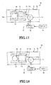
- a rail vehicle 1H according to this embodiment illustrated in FIG. 17 and 18 comprises the same construction as the embodiments described above. Consequently, with this embodiment also, the same actions and results (beneficial effects) are obtained as in the case of the aforementioned identical construction.
- This embodiment differs from the embodiments described above in that the aperture condition of the aperture portion 5d can be set in a variable fashion.
- a flow rate control section 10 comprises for example a movable section 11 or guide section 12, drive section 13, control circuit 14 and sensor 15.
- the movable section 11 is guided in the guide section 12 and is capable of movement between a position (position shown in FIG. 17 ) in which it covers (blocks) the aperture 5d and a position (position shown in FIG.
- the movable section 11 comprises a cover 11a and an arm 11b (rack section).
- the guide section 12 is constituted as a rail that guides the movable section 11 (in this embodiment, as one example, the cover 11a).
- the drive section 13 can be constituted as a motor having a pinion 13a.
- the pinion 13a meshes with a rack (not shown) are provided on the arm 11b. In this way, the drive section 13 can alter the position of the cover 11a of the movable section 11 i.e. the aperture area of the aperture portion 5d, by means of the rotational position of the pinion 13a.
- the control circuit 14 controls rotation of the drive section 13.
- the sensor 15 is constituted for example as a temperature sensor that detects the temperature within the equipment 3 (housing 3c) .
- the control circuit 14 can for example increase the flow rate of cooled air that is introduced into the equipment 3 (housing 3c) through the aperture portion 5d by increasing the aperture area of the aperture portion 5d, in cases where the temperature of the items of equipment 3, 30 is high. Also, the control circuit 14 can for example decrease the flow rate of cooled air introduced into the equipment 3 (housing 3c) through the aperture portion 5d by decreasing the aperture area of the aperture portion 5d in cases where the temperature within the equipment 3, 30 is low. In this way, with this embodiment, as one example, the temperature and/or humidity within the equipment 3 (housing 3c) can be independently regulated. Also, the temperature and/or humidity within the equipment 3 (housing 3c) can be more finely regulated.
- the present invention may be employed in a rail vehicle that accommodates various items of electrical equipment and the like, in which temperature regulation of these items of equipment and the like is carried out.
Landscapes
- Engineering & Computer Science (AREA)
- Mechanical Engineering (AREA)
- Automation & Control Theory (AREA)
- Transportation (AREA)
- Air-Conditioning For Vehicles (AREA)
- Cooling Or The Like Of Electrical Apparatus (AREA)
- Electric Propulsion And Braking For Vehicles (AREA)
Abstract
Description
- Rail vehicles are previously known in which a main conversion device or power conversion device or the like is cooled by air (air or the atmosphere). An example of such a rail vehicle is disclosed in Laid-open Japanese Patent Application Number
Tokkai 2010-69919 - In conventional rail vehicles, the layout of temperature control (temperature regulation) was often altered in accordance with the shape and disposition of the various items of equipment such as the main converters carried in each rail vehicle as a whole.
- Thus it would be desirable to be able to achieve temperature regulation of the various items of equipment or the equipment provided in the housing irrespective of the position in which the plurality of items of equipment are installed in the rail vehicle.
- A rail vehicle according to an embodiment of the present invention comprises: equipment, an air conditioner and a duct. A plurality of items of equipment are provided within a compartment. The air-conditioner conditions the air that is flowing within the items of equipment or within a housing in which the equipment is accommodated. The duct feeds air between the air-conditioner and the equipment and comprises a portion that extends along the forward/rearward direction of the vehicle in a position adjacent to the wall of the compartment, within this compartment.
-
-
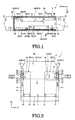
FIG. 1 is a diagrammatic plan view showing an example of the internal layout of a rail vehicle according to a first embodiment; -
FIG. 2 FIG. 2 is a diagrammatic cross-sectional view along the line II-II ofFIG. 1 of an example of a rail vehicle according to the first embodiment; -
FIG. 3 is a partial diagrammatic cross-sectional view of an example of a rail vehicle according to the first embodiment, at a position different from that ofFIG. 2 ; -
FIG. 4 is a partial diagrammatic cross-sectional view of a rail vehicle according to the first embodiment, at a position different from that ofFIG. 2 andFIG. 3 ; -
FIG. 5 is a side view, seen from inside the compartment, of part of a duct employed in an example of a rail vehicle according to the first embodiment; -
FIG. 6 is a view showing the condition in which an aperture portion is formed in one of sections where aperture formation in the duct ofFIG. 5 is possible; -
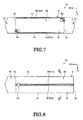
FIG. 7 is a diagrammatic plan view showing the arrangement of the air-conditioner and duct in an example of a rail vehicle according to a second embodiment; -
FIG. 8 is a diagrammatic plan view showing the arrangement of the air-conditioner and duct in an example of a rail vehicle according to a third embodiment; -
FIG. 9 is a diagrammatic cross-sectional view along the line IX-IX ofFIG. 8 of an example of a rail vehicle according to the third embodiment; -
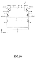
FIG. 10 is a diagrammatic cross-sectional view of an example of a rail vehicle according to a fourth embodiment; -
FIG. 11 is a diagrammatic cross-sectional view of the example of a rail vehicle according to a fourth embodiment at a position different from that ofFIG. 10 ; -
FIG. 12 is a diagrammatic cross-sectional view showing the arrangement of the air conditioner and duct of an example of a rail vehicle according to a fifth embodiment; -
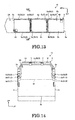
FIG. 13 is a diagrammatic plan view showing the arrangement of the air-conditioner and duct of an example of a rail vehicle according to a sixth embodiment; -
FIG. 14 is a diagrammatic cross-sectional view along the line XIV-XIV ofFIG. 13 , showing an example of a rail vehicle according to a sixth embodiment; -
FIG. 15 is a side view seen from inside a compartment, showing part of a duct employed in an example of a rail vehicle according to a seventh embodiment; -
FIG. 16 is a layout diagram of an air conditioning system of equipment employed in an example of a rail vehicle according to an eighth embodiment; -
FIG. 17 is a diagram of an aperture portion whose aperture area is changed, provided in a duct employed in an example of a rail vehicle according to a ninth embodiment, showing the condition in which the aperture is closed; and -
FIG. 18 is a diagram of an aperture portion whose aperture area is changed, provided in a duct employed in an example of a rail vehicle according to the ninth embodiment, showing the condition in which the aperture is open. - Similar structural elements are included in a plurality of embodiments, which are described by way of example below. Accordingly, these similar structural elements are given the same reference symbols in order to avoid repeated description. Also, for convenience, in the various Figures, arrows are attached to indicate direction. FR represents forwards in the forward/rearward direction of the vehicle; LH represents the left-hand side in the width direction of the vehicle (i.e. rightwards towards the direction of forward travel of the vehicle) ; and UP represents the upwards direction of the vehicle. It should be noted that forwards and rearwards may be interchanged, depending on the direction of forward travel.
- In the present embodiment shown in
FIG. 1 to 5 , as one example shown inFIG. 1 , a plurality ofcompartments 2A to 2C (in this embodiment, by way of example, three compartments) are provided in thecar body 2 of a rail vehicle 1 (which could be a locomotive or an electric vehicle). Thecompartment 2A is provided at the end on one side in the forward/rearward direction of the vehicle (in this embodiment, by way of example, on the front side), and the compartment 2C is provided at the end on the other side in the forward/rearward direction of the vehicle (in this embodiment, by way of example, on the rear side). Thecompartment 2B is positioned between thecompartment 2A and the compartment 2C. Thecompartment 2B is longer (wider) in the forward/rearward direction of the vehicle than thecompartments 2A and 2C. Also, thecompartments 2A to 2C are respectively divided bywalls 2a (partitions). Thewalls 2a are positioned on both sides of thecompartment 2B in the forward/rearward direction of the vehicle. Thewalls 2a extend in the vehicle width direction and in the vertical direction. Thewalls 2a are substantially flat rectangular-shaped and plate-shaped. Also, irregularities, apertures, doors and reinforcing members and the like are provided in thewall 2a. Thecompartments 2A, 2C are crew rooms (operation room, control room, driver room, conductor room) occupied by the operator (crew) etc. Thecompartment 2B is an equipment room (machinery room) whereequipment - Also, in this embodiment, as one example, as shown in
FIG. 1 , theequipment 3 provided in thecompartment 2B comprises for example a special high-voltage equipment frame 3A ormain converter 3B, an auxiliarypower source device 3C, anauxiliary frame 3D, amain blower 3E,brake control equipment 3F, and asafety device 3G. - Also, within the
housing 3c (casing, accommodating section, box, frame, space, seeFIG. 2 ) of themain converter 3B, there is accommodated acontrol unit 3H (equipment 30) of thismain converter 3B. A control unit 3I (equipment 30) of the auxiliarypower source device 3C is accommodated within thehousing 3c of this auxiliarypower source device 3C. - Also, a
vehicle control device 3J (equipment 30) is accommodated within thehousing 3c of theauxiliary frame 3D. The air-conditioner 4A conditions (regulates) the air within thecompartment 2A. Theair conditioner 4B conditions the air within the compartment 2C. Also, theair conditioner 4A conditions the air which is delivered to theequipment 3 and that flows in thespace 3b (seeFIG. 2 ) within thehousing 3c of thisequipment 3. In other words, the air-conditioner 4A is shared for conditioning the air within thecompartment 2A (second compartment) and for conditioning (conditioning of the environment surrounding the equipment 30) of the air which is delivered to theequipment 3 in thecompartment 2B and that flows in thespace 3b within thehousing 3c of thisequipment 3. It should be noted that, although, within the air-conditioner 4A, the temperature regulation sections (such as for example a cooling section or heating section, not shown) for thecompartment 2A and for the items ofequipment conditioner 4A, the route taken by the air directed into thecompartment 2A and the route taken by the air directed to theequipment items equipment 3 is not restricted to that described above. Theequipment 3 may include various types of device, such as for example electrical equipment or electronic equipment, a prime mover (internal combustion engine), a motor, and a storage battery (secondary battery). - Also, the temperature of the components in the
housing 3c (electrical components, electronic components, heating portions) andequipment 30 accommodated in thehousing 3c is regulated by means of the conditioned air flowing in thehousing 3c of theequipment 3. As theequipment 30 provided in thehousing 3c of theequipment 3, apart from thecontrol units vehicle control device 3J, there may be provided for example other control units (control circuit boards, units, electronic circuits) or circuit board assemblies, circuit boards, relays, switches, contactors, inverters, converters, power conversion units, capacitors, storage batteries (secondary batteries), electrical components and electronic components. It should be noted that there is no need to constructindividual housings 3c corresponding to individual items ofequipment 30. Although not shown, an arrangement could be adopted in which, corresponding to the plurality of items ofequipment 30, a sharedhousing 3c is constituted for the arrangement of this plurality of items ofequipment 30 within thehousing 3c; air is introduced into the interior of thishousing 3c; and conditioned air is blown into the this plurality of items ofequipment 30. - Also, an arrangement could be adopted in which conditioned air is blown onto some of the items of
equipment 30, of the plurality of items ofequipment 30 accommodated in thishousing 3c, but conditioned air is not blown onto other items ofequipment 30. Also, as shown inFIG. 2 , it could be arranged to introduce conditioned air into part of thehousing 3c (i.e. to restrict the region in thehousing 3c to which conditioned air is supplied), to condition the flow of air within thehousing 3c, or to provide a construction or shape of the example the wall 3d or other portions within thehousing 3c to achieve this effect. The items ofequipment conditioner 4A is fed to the items ofequipment duct 5, seeFIG. 2 ) . Also, the air that is allowed to flow within the equipment 3 (housing 3c) is returned to theair conditioner 4A through a return duct 52 (return portion, duct 5). Specifically, in this embodiment, as one example, the air for the items ofequipment 3, 30 (within thehousing 3c) is unlikely to become contaminated, since it is circulated through exclusive-use ducts 5. - Also, in this embodiment, as one example, as shown in
FIG. 1 and FIG. 2 , thecompartment 2B is enclosed by awall 2b (bottom wall, floor wall, lower wall), twowalls 2c (sidewalls) and awall 2d (ceiling wall, top wall).FIG. 2 is a diagrammatic cross-sectional view along the line II-II ofFIG. 1 . - The
wall 2b is positioned below thecompartment 2B. Thewall 2b extends along the vehicle forward/rearward direction and along the vehicle width direction. Also, thewall 2b is substantially flat rectangular-shaped and plate-shaped. Thewalls 2c are positioned on both sides of thecompartment 2B in the vehicle width direction. Thewalls 2c extend along the vehicle forward/rearward direction and the vertical direction. Also, thewalls 2c are substantially flat rectangular-shaped and plate-shaped. Thewall 2d has a central section 2d1 and two end sections 2d2. The central section 2d1 is positioned on the upper side of thecompartment 2B and in the central section thereof in the vehicle width direction. The central section 2d1 extends in the vehicle forward/rearward direction and the vehicle width direction. The central section 2d1 is substantially flat rectangular-shaped and plate-shaped. The end section 2d2 is positioned on the upper side of thecompartment 2B and between the central section 2d1 and thewalls 2c at both ends in the vehicle width direction. The end section 2d2 extends in the forward/rearward direction of the vehicle. The end section 2d2, whenFIG. 2 is viewed in front elevation, extends in an inclined upwards direction towards the inside in the vehicle width direction, going upwardly. Also, the end section 2d2 is substantially flat rectangular-shaped and plate-shaped. In thewalls walls walls compartment 2B, there is provided aframe 2e that functions as for example pillars or beams or a skeleton. Theframe 2e is provided extending along the forward/rearward direction of the vehicle, the vertical direction and the vehicle width direction. Theframe 2e may have a hollow (closed cross-section) or solid ("solid", in contrast to "hollow" means that the central portion is not hollowed out) cross-sectional shape. - Also, in this embodiment, as one example, as shown in
FIG. 2 , items of equipment 3 (housings 3c) are installed, by means of mountingfittings 31 or the like, on thewall 2b. Also, as shown inFIG. 1 and FIG. 2 , the items of equipment 3 (housings 3c) are arranged closer to (in the vicinity of or adjacent to) thewall 2c, of the two sides in the vehicle width direction; in this way, a space S is provided between one item of equipment 3 (housing 3c) and another item of equipment 3 (housing 3c); this space S constitutes a working space or a passage whereby workers (operators) or crew etc can pass. - Also, in this embodiment, as one example, as shown in
FIG. 1 and FIG. 2 , theduct 5 comprises: afirst portion 5a (extension, first extension), and asecond portion 5b (extension, second extension) and athird portion 5c (intermediate portion). Thefirst portion 5a extends along the forward/rearward direction of the vehicle on one side in the vehicle width direction of thecompartment 2B (in the case of this embodiment, as one example, the left-hand side). Thefirst portion 5a is positioned adjacent to thewall 2c at the end in the width direction on the upper side from the central region M in the vertical direction of thecompartment 2B (or upper side from the central region in the vertical direction of thewall 2c) i.e. at the upper side of thecompartment 2B and at the corner on one side in the vehicle width direction. Also, thefirst portion 5a extends along the upper edge of thewall 2c. Thesecond portion 5b extends along the forward/rearwards direction of the vehicle on the other side in the vehicle width direction of thecompartment 2B (in this embodiment, as one example, the right-hand side). Thesecond portion 5b is positioned adjacent to thewall 2c at the end in the vehicle width direction on the upper side from the central region M in the vertical direction of thecompartment 2B (or on the upper side from the central region in the vertical direction of thewall 2c) i.e. at the upper side of thecompartment 2B and in the corner on the other side in the vehicle width direction. Also, thesecond portion 5b extends along the edge on the upper side of thewall 2c. Thethird portion 5c extends along the vehicle width direction on one side (in this embodiment, as one example, the front side) of thecompartment 2B in the forward/rearwards direction of the vehicle. Also, although not shown, thethird portion 5c is positioned on the upper side from the central region M in the vertical direction of thecompartment 2B (or the upper side from the central region in the vertical direction of thewall 2a). Thethird portion 5c bridges thefirst portion 5a and thesecond portion 5b. Also, thethird portion 5c links thefirst portion 5a and thesecond portion 5b. It should be noted that, while, inFIG. 1 , only thereturn duct 52 is shown, thedelivery duct 51 and thereturn duct 52 are respectively provided with afirst portion 5a, asecond portion 5b and athird portion 5c. Also, in this embodiment, as one example, thedelivery duct 51 and returnduct 52 communicate through the interior of theair conditioner 4A or the interior of the equipment 3 (housings 3c), but are not in direct communication. Also, the heat insulating properties (heat shielding ability) of theduct 5 are improved by for example constructing the duct of material of high heat insulating properties, provision of a heat insulating layer, provision of an air layer, or by heat insulation treatment. Also, in this embodiment, as one example, theduct 5 has a substantially rectangular-shaped closed cross-sectional shape, but could have another closed cross-sectional shape (such as for example a circular shape). - Also, in this embodiment, as one example, as shown in
FIG. 2 , in the case of thefirst portion 5a andsecond portion 5b thereof, respectively extending along thewall 2c, thereturn duct 52 is positioned above thedelivery duct 51. Also, although not shown, even in the case of thethird portion 5c along thewall 2a, thereturn duct 52 is positioned above thedelivery duct 51. The temperature of the air of thereturn duct 52 is often higher than the temperature of the air of thedelivery duct 51, since the air of thereturn duct 52 is heated by the items ofequipment return duct 52 is positioned above thedelivery duct 51, thedelivery duct 51 is unlikely to be affected by the heat of thereturn duct 52 i.e. is unlikely to be heated thereby. Also, when the air in thespace 3b within the equipment 3 (housings 3c) is heated, this heated air can easily escape to thereturn duct 52 that is positioned above the items ofequipment 3. - Also, in this embodiment, as one example, as shown in
FIG. 2 , at least part of the equipment 3 (housing 3c) is provided adjacent to theduct 5, and anaperture portion 3a provided in theequipment 3 and anaperture portion 5d (aperture) provided in theduct 5 are mutually opposite and superimposed in the vehicle width direction. Leakage of gases or permeation of liquids etc between theaperture portion 3a and theaperture portion 5d is suppressed by sealing by means of a sealing member 32 (such as for example an O-ring or packing or a gasket). In this embodiment, as one example, a construction is adopted such that sealing by the sealingmember 32 is improved by clamping of the sealingmember 32 between theequipment 3 and theduct 5 by mounting theequipment 3 on the car body 2 (wall 2b) closer to the side of the duct 5 (i.e. the side of thewall 2c), thereby raising the face pressure of this sealingmember 32. In this way, in this embodiment, as one example, sealing performance between theequipment 3 and theduct 5 can easily be improved by a comparatively straightforward construction and comparatively easy mounting operation. - Also, in this embodiment, as one example, as shown in
FIG. 3 , the height of at least part of the item of equipment 3 (thehousing 3c) is lower than the position of theduct 5.FIG. 3 is a partial, diagrammatic cross-sectional view at a position different from that ofFIG. 2 . - In this case, a connecting
duct 6 is interposed between theduct 5 and the item ofequipment 3. The connectingduct 6 is fixed to theduct 5 by fixing using a fixing element (such as for example a screw) or coupling (for example welding deposition, bonding or welding). Theaperture portion 6a on one side of the connectingduct 6 and theaperture portion 5d of theduct 5 are superimposed, and theaperture portion 6b on the other side of theduct 6 and theaperture portion 3a of theequipment 3 are superimposed. The connecting portions of the connectingduct 6 and theequipment 3 are sealed by the sealingmember 32 or the like. Thus, in the construction ofFIG. 3 , in the same way as in the construction ofFIG. 2 , sealing by the sealingmember 32 is improved by clamping of the sealingmember 32 between theequipment 3 and theduct 6 by mounting theequipment 3 on the car body 2 (wall 2b) closer to the side of theduct 5, thereby raising the face pressure of this sealingmember 32. In this way, in this embodiment, as one example, sealing performance between theequipment 3 and theduct 6 can easily be improved by a comparatively straightforward construction and comparatively easy mounting operation. It should be noted that the connectingduct 6 could be employed even in the case where theaperture portion 3a of theequipment 3 and theaperture portion 5d of theduct 5 are offset in the forward/rearward direction of the vehicle. - Also, in this embodiment, as one example, as shown in
FIG. 4 , theduct 5 could be mounted by means of a mountingelement 7 on thewall 2c (orwall 2a orwall 2b orwall 2d).FIG. 4 is a partial diagrammatic cross-sectional view at a position different from that ofFIG. 2 andFIG. 3 . - A plurality of mounting
elements 7 are arranged with a separation in the forward/rearward direction of the vehicle. It should be noted that the construction ofFIG. 4 merely represents one example, and theduct 5 could be fixed by means of fixing elements (such as for example screws) to thewalls 2a to 2d etc. Also, a heat insulating member may be interposed between theduct 5 andwalls 2a to 2d orframe 2e. - Also, in this embodiment, as one example, as shown in
FIG. 5 , a plurality of aperture-forming-capable portions 8 may be provided in thewall section 5e of thecompartment 2B on the inside of theduct 5.FIG. 5 is a side face view seen from inside the compartment, of part of a duct that is employed in one example of a rail vehicle according to the first embodiment. - In an aperture-forming-capable portion 8, there are provided a plurality (in this embodiment, by way of example, four) of
recesses 8a (recessed grooves) of arcuate shape along a circle. The thickness of the portion where therecesses 8a are provided is less than the thickness of other portions (ordinary portions). By pressing the plurality ofrecesses 8a or the inside of the plurality ofrecesses 8a with the fingers or a tool, the operator excises aregion 8b (part of the cover section orwall section 5e) on the inside of theserecesses 8a and can thereby form anair aperture portion 5d of prescribed shape (size) as shown inFIG. 6 . Theregion 8b enclosed by the plurality ofrecesses 8a constitutes one example of a weakened portion (thin portion). The plurality of aperture-forming-capable portions 8 are provided with a fixed separation along the longitudinal direction of theduct 5. Specifically, in this embodiment, as one example, even if the position of arrangement of the items of equipment 3 (housing 3c) is changed, a path for the air between theduct 5 and the item ofequipment 3 can easily be constituted by providing the plurality of aperture-forming-capable portions 8 in a dispersed manner from the front side to the rear side in the forward/rearward direction of the vehicle. In other words, in this embodiment, as one example, the degrees of freedom of the layout of the items ofequipment 3 can easily be increased. - As described above, with this embodiment, as one example, a rail vehicle 1 comprises a
duct 5 within thecompartment 2, having afirst portion 5a andsecond portion 5b that feeds air between the air-conditioner 4A and the items ofequipment wall 2c of thecompartment 2 in question. In this way, in this embodiment, as one example, irrespective of the position of the items ofequipment compartment 2B in the forward/rearward direction of the vehicle, air that is conditioned by theair conditioner 4A can be applied to the various items ofequipment first portion 5a and thesecond portion 5b of theduct 5. Also, in this embodiment, as one example, more efficient regulation of temperature or humidity etc within the items ofequipment 3 can be achieved irrespective of the position in which these are respectively installed (position in the forward/rearward direction of the vehicle) . In this way, as one example, the degrees of freedom of the layout of the items ofequipment 3 within thecompartment 2B can be easily raised, irrespective of the amount of heat etc generated by these items ofequipment 3. Also, in this embodiment, as one example, theduct 5 can easily be installed within thecompartment 2B by utilizing thewalls 2c and/or theframe 2e or the like. In this way, with this embodiment, as one example, a rail vehicle 1 can easily be constituted as a standardized vehicle. Also, in this embodiment, as one example, in regard toequipment 3 whereequipment 30 is accommodated within thehousing 3c, replacement (ventilation or scavenging) of air within thehousing 3c (space 3b) by conditioned air, or regulation of temperature or humidity within thehousing 3c and regulation etc of the temperature of theequipment 30 can be performed. In addition, in some cases theequipment conditioner 4A can operate in a high-temperature environment. Accordingly, in this embodiment, as one example, in a high-temperature environment the air-conditioner 4A is operated so that the ambient temperature of the items ofequipment conditioner 4A: in this way, these items ofequipment equipment conditioner 4A, so that these items ofequipment equipment 3 or the items ofequipment 30, the time or cost involved in use of components of high heat-withstanding ability, or of taking countermeasures to withstand heat, or of performing heat-insulation measures can be easily reduced. - Also, in this embodiment, as one example, the
first portion 5a (extension) andsecond portion 5b (extension) are positioned at the ends in the vehicle width direction above the central region M in the vertical direction of thecompartment 2B. Consequently, in this embodiment, as one example, arrangement of the duct 5 (first portion 5a and/orsecond portion 5b) can easily be achieved by utilizing the region of thecompartment 2B at the ends thereof in the vehicle width direction and above the central region M thereof in the vertical direction, which tends to constitute a space (dead space) within thecompartment 2B which is comparatively free. Consequently, in this embodiment, as one example, interference between theduct 5 and the equipment 3 (housing 3c) and/or components etc can easily be suppressed and installation of theduct 5 can easily be effected in a condition in which there are fewer difficulties (inconveniences) within thecompartment 2B. Also, in this embodiment, as one example, the efficiency of utilization of the space within thecompartment 2B can easily be raised. Furthermore, in this embodiment, as one example, the degrees of freedom of the layout of the items of equipment 3 (housing 3c) in the vehicle width direction can be easily raised, as a result of the fact that air can be introduced into the equipment 3 (housing 3c) from either of thefirst portion 5a orsecond portion 5b. - Also, in this embodiment, as one example, the
duct 5 comprises afirst portion 5a (first extension) extending along the forward/rearward direction of the vehicle on one side in the vehicle width direction of thecompartment 2B and asecond portion 5b (second extension) extending along the forward/rearward direction of the vehicle on the other side in the vehicle width direction of thecompartment 2B; the items of equipment 3 (housing 3c) are positioned closer to one side or theother side wall 2c in the vehicle width direction of thecompartment 2B and the space S between the item of equipment 3 (housing 3c) that is positioned closest to thewall 2c on one side in the vehicle width direction and the item of equipment 3 (housing 3c) that is positioned closest to thewall 2c on the other side in the vehicle width direction extends along the forward/rearwards direction of the vehicle. Consequently, in this embodiment, as one example, the space S can be utilized as a passage or operating space for passage of workers (operators) or crew etc. Also, as one example, workers (operators) can have access to items ofequipment 3 on both sides in the vehicle width direction from the space S. Furthermore, as one example, in a rail vehicle 1 having an arrangement in which the space S is guaranteed in the central region in the vehicle width direction of thecompartment 2B, a layout whereby conditioned air can flow into thespace 3b within the plurality of items ofequipment 3 arranged in the forward/rearward direction of the vehicle can be more efficiently and more easily obtained. - Also, in this embodiment, as one example, the
duct 5 comprises: a delivery duct 51 (delivery portion) that delivers air from the air-conditioner 4A to theequipment 3, 30 (housing 3c) and that is provided closer to thewall 2c on one side in the vehicle width direction of thecompartment 2B and that extends along the forward/rearward direction of the vehicle; and a return duct 52 (return portion) that returns air from theequipment 3, 30 (housing 3c) to theair conditioner 4A and that is provided closer to thewall 2c on one side in the vehicle width direction and that is positioned above thedelivery duct 51 and that extends along the forward/rearward direction of the vehicle. In this way, with this embodiment, as one example, thedelivery duct 51 is unlikely to be affected by heat from thereturn duct 52 i.e. is unlikely to be heated up. Also, as one example, when the air in thespace 3b within the equipment 3 (housing 3c) is heated, such heated air is easily expelled from the equipment 3 (housing 3c) to thereturn duct 52 which is positioned thereabove. - Also, with this embodiment, as one example, the
duct 5 comprises afirst portion 5a (first extension) extending along the forward/rearward direction of the vehicle on one side in the vehicle width direction of thecompartment 2B; asecond portion 5b (second extension) extending along the forward/rearward direction of the vehicle on the other side in the vehicle width direction of thecompartment 2B; and athird portion 5c (intermediate portion) that bridges thefirst portion 5a and thesecond portion 5b and that links thefirst portion 5a and thesecond portion 5b. In this way, with this embodiment, as one example, a construction in which thefirst portion 5a and thesecond portion 5b are linked can be obtained by a comparatively straightforward construction. In this way, as one example, conditioned air can be supplied from asingle air conditioner 4A to afirst portion 5a andsecond portion 5b that extend along the forward/rearwards direction of the vehicle respectively on both sides in the vehicle width direction within thecompartment 2B, and in this way can be supplied to respective items ofequipment first portion 5a andsecond portion 5b. - Also, in this embodiment, as one example, the air-
conditioner 4A is shared by thecompartment 2B and acompartment 2A (second compartment) divided from thiscompartment 2B and that is provided in front of or behind (in this embodiment, as one example, in front) theaforementioned compartment 2B. In this way, in this embodiment, as one example, compared with the case where the air-conditioner is provided in each of thecompartments - Also, in this embodiment, as one example, in the
duct 5, there are provided a plurality of aperture-forming-capable portions 8 that are capable of formingair aperture portions 5d (apertures) by excising a portion thereof atrecesses 8a (weakened portion). In this way, with this embodiment, as one example, an operator can comparatively easily form anaperture portion 5d linking with anaperture portion 3a of the item of equipment 3 (housing 3c), by selecting an aperture-forming-capable portion 8. In this way, as an example, the degrees of freedom of the layout of theequipment 3, 30 (housing 3c) in thecompartment 2B can easily be increased. - A
rail vehicle 1A according to the present embodiment shown inFIG. 7 comprises the same construction as in the case of the embodiment described above. Consequently, in this embodiment also, the same action and effects (benefits) are obtained, based on the same construction as aforementioned. It should be noted that, inFIG. 7 , illustration of the items ofequipment 3, 30 (housing 3c) etc. is dispensed with. - In this embodiment, the construction of the air-
conditioners duct 5 etc are different from in the embodiment described above. Specifically, in this embodiment, as one example, thefirst portion 5a and thesecond portion 5b of theduct 5 are mutually isolated and are not linked. Air is delivered from theair conditioner 4B to (thedelivery duct 51, not shown inFIG. 7 , of) thesecond portion 5b and the air is returned from (thereturn duct 52 of) thesecond portion 5b of theair conditioner 4B. With this embodiment, as one example, the temperature and/or humidity etc of thespace 3b in the equipment 3 (housing 3c) can be more efficiently regulated by using two air-conditioners air conditioner 4B could also condition the air of the compartment 2C (second compartment). - A
rail vehicle 1B according to this embodiment illustrated inFIG. 9 andFIG. 10 comprises the same construction as the embodiments described above.FIG. 9 is a diagrammatic cross-sectional view along the line IX-IX ofFIG. 8 of an example of a rail vehicle according to the third embodiment. - Consequently, with this embodiment also, the same actions and results (beneficial effects) are obtained as in the case of the aforementioned identical construction. In
FIG. 8 andFIG. 9 , illustration of theequipment 3, 30 (housing 3c) etc. is dispensed with. In this embodiment, the construction of theduct 5 is different from that of the above embodiments. Specifically, in this embodiment, as one example, portions 5f, 5f constituting thedelivery duct 51 and returnduct 52 of theduct 5 are arranged in a parallel fashion at the top of thecompartment 2B and at the middle thereof in the vehicle width direction, and extend along the forward/rearward (backward) direction of the vehicle. Also, in this embodiment, as one example, aframe 2f (rafter) bridging the twoframes 2e is provided along thewall 2d on the upper side of thecompartment 2B. Theduct 5 is fixed to theframe 2f by means of a mountingelement 7. In this embodiment, as one example, when the equipment 3 (housing 3c) is positioned in the middle of thecompartment 2, conditioned air is easily supplied to theequipment - A
rail vehicle 1C according to this embodiment illustrated inFIG. 10 andFIG. 11 comprises the same construction as the embodiments described above. Consequently, with this embodiment also, the same actions and results (beneficial effects) are obtained as in the case of the aforementioned identical construction. InFIG. 10 , illustration of theequipment 3, 30 (housing 3c) etc. is dispensed with. In this embodiment, the construction of theduct 5 is different from that of the above embodiments. Specifically, in this embodiment, as one example,portions return duct 52 of theduct 5 are fixed to the edge 2d2 of thewall 2d by means of a mountingelement 7, at the top of thecompartment 2B and on both sides in the vehicle width direction. Theportions duct 6 is fixed to the return duct 52 (portions duct 6 that is fixed to thereturn duct 52 is pressed from above onto the equipment 3 (housing 3c) . Anaperture portion 6b of the connectingduct 6 and anaperture portion 3a of the item ofequipment 3 are superimposed. The connecting portion of the connectingduct 6 and the item ofequipment 3 are sealed by for example a sealingmember 32. In this embodiment, as one example, the connectingduct 6 that is fixed with theduct 5 to thewall 2d constituting the roof is mounted on the item ofequipment 3; the sealingmember 32 is thereby clamped between the item ofequipment 3 and the connecting duct 6: in this way, the face pressure of this sealingmember 32 is increased and a construction is achieved in which sealing performance by the sealingmember 32 is improved. With this embodiment, as one example, interference of thereturn duct 52 and the equipment 3 (housing 3c) and/or components thereof is even easier to suppress, so that thereturn duct 52 can easily be installed in a condition that presents even less difficulty in thecompartment 2B. Also, with this embodiment, as an example, the efficiency of utilization of the space in thecompartment 2B can easily be improved even further. It should be noted that thedelivery duct 51 can be provided along thewall 2d or both thedelivery duct 51 and thereturn duct 52 could be provided along thewall 2d. - A
rail vehicle 1D according to this embodiment illustrated inFIG. 12 comprises the same construction as the embodiments described above. Consequently, with this embodiment also, the same actions and results (beneficial effects) are obtained as in the case of the aforementioned identical construction. InFIG. 12 , illustration of theequipment 3, 30 (housing 3c) etc. is dispensed with. In this embodiment, the construction of thecar body 2 and theduct 5 is different from that of the above embodiments. Specifically, in this embodiment, as one example, the compartment 2C is absent and theair conditioner 4B performs conditioning of the air delivered to the equipment 3 (housing 3c) and flowing in thespace 3b within thehousing 3c. The air-conditioner 4A performs conditioning of the air within thecompartment 2A and of the air delivered to theequipment 3, 30 (housing 3c) and flowing in thespace 3b within the equipment 3 (housing 3c). Also, the air-conditioner 4A conditions the air within the equipment 3 (housing 3c) of thecompartment 2B that is arranged on the front side in the forward/rearward direction of the vehicle, and theair conditioner 4B conditions the air within the equipment 3 (housing 3c) of thecompartment 2B that is arranged on the rear side in the forward/rearward direction of the vehicle. Theduct 5 that is linked with the air-conditioner 4A comprises: afirst portion 5a that is positioned on one side in the vehicle width direction (in this embodiment, as one example, the left-hand side) ; asecond portion 5b that is positioned on the other side in the vehicle width direction (in this embodiment, as one example, the right-hand side) ; and athird portion 5c extending in the vehicle width direction, that connects the end of thefirst portion 5a on one side (in this embodiment, as one example, the rear side) in the forward/rearwards direction of the vehicle and the end on one side of thesecond portion 5b in the forward/rearward direction of the vehicle, thus presenting, overall, a U-shape. Also, theduct 5 that is linked with the air-conditioner 4B comprises: afirst portion 5a that is positioned on the other side in the vehicle width direction; asecond portion 5b that is positioned on the one side in the vehicle width direction; and athird portion 5c extending in the vehicle width direction, that connects the end of thefirst portion 5a on the other side in the forward/rearwards direction of the vehicle and the end on the other side of thesecond portion 5b in the forward/rearward direction of the vehicle (in this embodiment, as one example, the front side), thus presenting, overall, a U-shape. With this embodiment, as one example, the temperature and/or humidity etc of thespace 3b in the equipment 3 (housing 3c) can be more efficiently regulated by using two air-conditioners conditioners equipment compartment 2B is different. Specifically, the region that can be served by theair conditioner 4A (region surrounded by theduct 5 linked with the air-conditioner 4A) is more restricted than the region that can be served by theair conditioner 4B (region surrounded by theduct 5 linked with theair conditioner 4B). In this embodiment, the air-conditioner 4A performs conditioning of the air in thecompartment 2A, so the region in which the air-conditioner 4A serves theequipment compartment 2B is more restricted than the region in which the air-conditioner 4B serves theequipment compartment 2B. Consequently, in this embodiment, as one example, the two air-conditioners - A
rail vehicle 1E according to this embodiment illustrated inFIG. 13 and 14 comprises the same construction as the embodiments described above. It may be noted thatFIG. 14 is a diagrammatic cross-sectional view along the line XIV-XIV ofFIG. 13 . - Consequently, with this embodiment also, the same actions and results (beneficial effects) are obtained as in the case of the aforementioned identical construction. In
FIG. 13 and 14 , illustration of theequipment 3, 30 (housing 3c) etc. is dispensed with. In this embodiment, the construction of thecar body 2 and theduct 5 is different from that of the above embodiments. Specifically, in this embodiment, as one example, the compartment 2C is absent and theair conditioner 4B performs conditioning of the air delivered to the equipment 3 (housing 3c) and flowing in thespace 3b within thehousing 3c. The air-conditioner 4A performs conditioning of the air within thecompartment 2A and of the air delivered to theequipment 3, 30 (housing 3c) and flowing in thespace 3b within the equipment 3 (housing 3c). Also, the air-conditioner 4A conditions the air within the equipment 3 (housing 3c) of thecompartment 2B that is arranged on the front side in the forward/rearward direction of the vehicle, and theair conditioner 4B conditions the air within the equipment 3 (housing 3c) of thecompartment 2B that is arranged on the rear side in the forward/rearward direction of the vehicle. Theduct 5 that is linked with the air-conditioner 4A comprises: afirst portion 5a that is positioned on one side in the vehicle width direction (in this embodiment, as one example, the left-hand side); asecond portion 5b that is positioned on the other side in the vehicle width direction (in this embodiment, as one example, the right-hand side); and athird portion 5c extending in the vehicle width direction, that connects an intermediate portion of thefirst portion 5a in the forward/rearward direction of the vehicle and the end of thesecond portion 5b on one side (in this embodiment, as one example, the rearward side) in the forward/rearward direction of the vehicle: overall, an h shape is thus constituted. Also, theduct 5 that is linked with the air-conditioner 4B comprises: afirst portion 5a that is positioned on the other side in the vehicle width direction; asecond portion 5b that is positioned on one side in the vehicle width direction; and athird portion 5c extending in the vehicle width direction, that connects an intermediate portion of thefirst portion 5a in the forward/rearward direction of the vehicle and the end of thesecond portion 5b on the other side (in this embodiment, as one example, the forward side) in the forward/rearward direction of the vehicle: overall, an h shape is thus constituted. With this embodiment, as one example, the temperature and/or humidity etc of thespace 3b in the equipment 3 (housing 3c) can be more efficiently regulated by using two air-conditioners third portion 5c of thedelivery duct 51 is positioned on one side (in the forward/rearward direction of the vehicle) in the width direction of theframe 2f (in this embodiment, as one example, the rear side in the forward/rearward direction of the vehicle); and thethird portion 5c of thereturn duct 52 is positioned on the other side in the width direction of theframe 2f. Thethird portion 5c is fixed to theframe 2f through the mountingelement 7. In this way, in this embodiment, as one example, thethird portion 5c can be arranged more easily or more efficiently. - A
rail vehicle 1F according to this embodiment illustrated inFIG. 15 comprises the same construction as the embodiments described above. Consequently, with this embodiment also, the same actions and results (beneficial effects) are obtained as in the case of the aforementioned identical construction. InFIG. 15 , illustration of theequipment 3, 30 (housing 3c) etc. is dispensed with. In this embodiment, the construction of thecar body 2 and theduct 5 is different from that of the above embodiments. Specifically, in this embodiment, as one example, the (edge 2d2 of the)wall 2d constituting the wall where theportion 5h of theduct 5 is mounted is divided at a plurality of positions P (boundary portions). In this case, thewall 2d is placed from above on the side of thewall 2c. On thewall 2c, there are providedU-shaped portions 5i (connecting sections) linking mutuallyadjacent portions 5h. Each of theends 5j (aperture portions) where theportions 5i andportions 5h are connected is open towards the top and each of the ends 5k (aperture portions) where theportions 5i andportions 5h are connected is open towards the bottom. In this way, theportions 5h andportions 5i that are provided on eachwall 2d are put in communication by placing the twowalls 2d from above on thewall 2c. Consequently, in this embodiment, as one example, a series ofducts 5 can be more easily constituted with theportions 5h of theducts 5 provided on a plurality of walls linked in a comparatively easy fashion. Also, in this embodiment, as one example, a construction can easily be obtained in which overlapping connecting portions of theends 5j, 5k are sealed (for example using O-rings, not shown). Also, in this embodiment, as one example, ifframes 2f are provided corresponding to the positions P bridging the top of thecompartment 2B in the vehicle width direction, a construction can easily be obtained in which interference of theducts 5 andframes 2f is suppressed by enabling theducts 5 to bypass theframes 2f. - A
rail vehicle 1G according to this embodiment illustrated inFIG. 16 comprises the same construction as the embodiments described above. Consequently, with this embodiment also, the same actions and results (beneficial effects) are obtained as in the case of the aforementioned identical construction. In this embodiment, the construction of theair conditioner 4A and theduct 5 is different from that of the above embodiments. Specifically, in this embodiment, as one example, the air-conditioner 4A comprises for example: a cooling section 4A1 (cooling device) and heating section 4A2 (heating device) and a changeover section 9 (damper). Thechangeover unit 9 can change over between a condition in which the cooling unit 4A1 is in communication with theduct 5 and a condition in which the heating section 4A2 is in communication with theduct 5. In this way, in this embodiment, as one example, by changing over thechangeover section 9, the air-conditioner 4A can be utilized as a cooling section or can be utilized as a heating section. - A
rail vehicle 1H according to this embodiment illustrated inFIG. 17 and 18 comprises the same construction as the embodiments described above. Consequently, with this embodiment also, the same actions and results (beneficial effects) are obtained as in the case of the aforementioned identical construction. This embodiment differs from the embodiments described above in that the aperture condition of theaperture portion 5d can be set in a variable fashion. Specifically, in this embodiment, as one example, a flowrate control section 10 comprises for example amovable section 11 orguide section 12,drive section 13,control circuit 14 andsensor 15. Themovable section 11 is guided in theguide section 12 and is capable of movement between a position (position shown inFIG. 17 ) in which it covers (blocks) theaperture 5d and a position (position shown inFIG. 18 ) in which it opens theaperture portion 5d. Themovable section 11 comprises acover 11a and anarm 11b (rack section). Theguide section 12 is constituted as a rail that guides the movable section 11 (in this embodiment, as one example, thecover 11a). Thedrive section 13 can be constituted as a motor having apinion 13a. Thepinion 13a meshes with a rack (not shown) are provided on thearm 11b. In this way, thedrive section 13 can alter the position of thecover 11a of themovable section 11 i.e. the aperture area of theaperture portion 5d, by means of the rotational position of thepinion 13a. Thecontrol circuit 14 controls rotation of thedrive section 13. Thesensor 15 is constituted for example as a temperature sensor that detects the temperature within the equipment 3 (housing 3c) . Thecontrol circuit 14 can for example increase the flow rate of cooled air that is introduced into the equipment 3 (housing 3c) through theaperture portion 5d by increasing the aperture area of theaperture portion 5d, in cases where the temperature of the items ofequipment control circuit 14 can for example decrease the flow rate of cooled air introduced into the equipment 3 (housing 3c) through theaperture portion 5d by decreasing the aperture area of theaperture portion 5d in cases where the temperature within theequipment housing 3c) can be independently regulated. Also, the temperature and/or humidity within the equipment 3 (housing 3c) can be more finely regulated. - While embodiments of the invention have been described above, these merely represent examples thereof and are not intended to restrict the scope of the invention. These embodiments may be put into practice in various other modes and various deletions, substitutions, combinations or modifications may be performed without departing from the gist of the invention. Such embodiments or modifications thereof are included within the scope or gist of the invention and are included in the invention set out in the patent claims and equivalents thereof. Also, the specification of the various structural elements (such as their construction, type, direction, shape, size, length, width, thickness, height, number, arrangement, position and material) may be suitably altered when these embodiments are put into practice. For example, the present invention may be applied to a compartment in the bonnet portion of a bonnet-type locomotive.
- The present invention may be employed in a rail vehicle that accommodates various items of electrical equipment and the like, in which temperature regulation of these items of equipment and the like is carried out.
Claims (7)
- A rail vehicle comprising:a plurality of items of equipment provided within a compartment;an air-conditioner that conditions an air flowing within said item of equipment or within a housing that accommodates said item of equipment; anda duct that delivers air between said air conditioner and said item of equipment and having a portion extending within said compartment in a forward/rearward direction of a vehicle, in a position close to a wall of said compartment.
- The rail vehicle according to claim 1,
wherein a portion extending along said forward/rearward direction of said vehicle in a position close to said wall of said compartment within said compartment is positioned at an end in a vehicle width direction above a central portion of said compartment in a vertical direction. - The rail vehicle according to claim 1 or 2,
wherein said duct comprises:a first extension that extends along said forward/rearward direction of said vehicle, positioned on one side in said vehicle width direction of said compartment; anda second extension that extends along said forward/rearward direction of said vehicle, positioned on another side in said vehicle width direction of said compartment,wherein said items of equipment are positioned closer to said wall on one side or another side in said vehicle width direction of said compartment, and a space between said item of equipment that is positioned closer to said wall on one side in said vehicle width direction and said item of equipment that is positioned closer to said wall on another side in said vehicle width direction extends along said forward/rearward direction of said vehicle. - The rail vehicle according to claim 1 or 2,
wherein said duct comprises, as portions extending along said forward/rearward direction of said vehicle in positions closer to said wall of said compartment, within said compartment:a delivery portion that delivers air to said item of equipment, provided closer to said wall on one side of said compartment in said vehicle width direction; anda return portion that returns air to said air conditioner from said item of equipment, arranged closer to said wall on one side in said vehicle width direction, above said delivery portion. - The rail vehicle according to claim 1 or 2,
wherein said duct comprises:a first extension extending along said forward/rearward direction of said vehicle positioned on one side in said vehicle width direction of said compartment;a second extension extending along said forward/rearward direction of said vehicle positioned on another side in said vehicle width direction of said compartment; andan intermediate section that bridges said first extension and said second extension and links said first extension and second extension. - The rail vehicle according to claim 1 or 2,
wherein said air conditioner is shared by a first compartment with a second compartment that is provided in front of or to a rear of said first compartment, and that is divided from said first compartment. - The rail vehicle according to claim 1 or 2,
wherein said duct is provided with a plurality of aperture-forming-capable sections capable of forming air apertures by excision of a portion of a weakened section.
Applications Claiming Priority (2)
| Application Number | Priority Date | Filing Date | Title |
|---|---|---|---|
| JP2012212478A JP5897442B2 (en) | 2012-09-26 | 2012-09-26 | Railway vehicle |
| PCT/JP2013/001585 WO2014049895A1 (en) | 2012-09-26 | 2013-03-12 | Railway vehicle |
Publications (3)
| Publication Number | Publication Date |
|---|---|
| EP2902298A1 true EP2902298A1 (en) | 2015-08-05 |
| EP2902298A4 EP2902298A4 (en) | 2016-05-18 |
| EP2902298B1 EP2902298B1 (en) | 2019-11-20 |
Family
ID=50387351
Family Applications (1)
| Application Number | Title | Priority Date | Filing Date |
|---|---|---|---|
| EP13841037.8A Active EP2902298B1 (en) | 2012-09-26 | 2013-03-12 | Railway vehicle |
Country Status (7)
| Country | Link |
|---|---|
| US (1) | US10112626B2 (en) |
| EP (1) | EP2902298B1 (en) |
| JP (1) | JP5897442B2 (en) |
| CN (1) | CN104619570B (en) |
| IN (1) | IN2015DN01666A (en) |
| WO (1) | WO2014049895A1 (en) |
| ZA (1) | ZA201501401B (en) |
Families Citing this family (5)
| Publication number | Priority date | Publication date | Assignee | Title |
|---|---|---|---|---|
| CN105083311B (en) * | 2015-06-04 | 2018-08-31 | 山东朗进科技股份有限公司 | A kind of air-conditioner set and the suspension type hanger rail vehicle for being equipped with the air-conditioner set |
| DE102018220741B3 (en) * | 2018-11-30 | 2020-04-23 | Siemens Mobility GmbH | Heat dissipation device for a rail vehicle and rail vehicle |
| JP7249843B2 (en) * | 2018-12-28 | 2023-03-31 | 株式会社東芝 | bolster module |
| FR3106556B1 (en) * | 2020-01-23 | 2022-02-11 | Speedinnov | Railway engine with device for fixing technical equipment |
| JP7433547B2 (en) * | 2021-09-29 | 2024-02-19 | 三菱電機株式会社 | In-vehicle equipment |
Family Cites Families (24)
| Publication number | Priority date | Publication date | Assignee | Title |
|---|---|---|---|---|
| US2709967A (en) * | 1949-08-13 | 1955-06-07 | Gen Motors Corp | Cooling and ventilating system for generating electric locomotives |
| US3862549A (en) * | 1972-11-29 | 1975-01-28 | United Aircraft Prod | Modular environmental control system |
| JPS51127514U (en) * | 1975-04-11 | 1976-10-15 | ||
| JPS55125863U (en) * | 1979-03-02 | 1980-09-05 | ||
| JPS60255570A (en) * | 1984-06-01 | 1985-12-17 | 株式会社日立製作所 | Vehicle air supply system |
| FR2600607B1 (en) * | 1986-06-27 | 1990-04-13 | Alsthom | HEATING AND VENTILATION DEVICE FOR A RAILWAY CAR CONSISTING OF TWO SINGLE-STOREY END COMPARTMENTS AND A TWO-STOREY CENTRAL COMPARTMENT |
| JPS6389874U (en) * | 1986-12-03 | 1988-06-10 | ||
| JP2732487B2 (en) * | 1991-04-23 | 1998-03-30 | 川崎重工業株式会社 | Vehicle ventilation system |
| AU641327B1 (en) * | 1992-10-27 | 1993-09-16 | Kawasaki Jukogyo Kabushiki Kaisha | Ventilating apparatus for conveyance |
| EP0625456B1 (en) * | 1993-05-21 | 1998-09-23 | SLM Schweizerische Lokomotiv- und Maschinenfabrik AG | Device for ventilating at least one traction motor and/or one cooling system of a railway traction unit and railway traction unit provided with such a device |
| US6238282B1 (en) * | 1999-11-30 | 2001-05-29 | General Electric Company | Locomotive cabin ventilation apparatus and method |
| DE102005057541A1 (en) * | 2005-12-01 | 2007-06-14 | Siemens Ag | Installation of a cooling system in a rail vehicle, in particular a railcar train |
| US20100006261A1 (en) * | 2006-09-19 | 2010-01-14 | Mitsubishi Electric Corporation | Moving Body Cooling Apparatus |
| CN200977914Y (en) * | 2006-11-08 | 2007-11-21 | 中国南车集团资阳机车有限公司 | Dry-type cooling system for diesel locomotive |
| US8511237B2 (en) * | 2007-07-19 | 2013-08-20 | Mitsubishi Heavy Industries, Ltd. | Guideway electric vehicle mounted with batteries |
| JP2009234310A (en) * | 2008-03-26 | 2009-10-15 | Hitachi Ltd | Rail vehicle |
| JP5178278B2 (en) * | 2008-03-28 | 2013-04-10 | 株式会社東芝 | Railway vehicle cooling device and railway vehicle equipped with the same |
| CN201214411Y (en) * | 2008-04-23 | 2009-04-01 | 中国北车集团大同电力机车有限责任公司 | Ventilation apparatus for vehicle makeup air |
| DE102008025540A1 (en) * | 2008-05-27 | 2009-12-17 | Siemens Aktiengesellschaft | locomotive |
| JP2010069919A (en) | 2008-09-16 | 2010-04-02 | Toshiba Corp | Railroad vehicle |
| DE102009031237A1 (en) * | 2009-06-26 | 2011-01-05 | Siemens Aktiengesellschaft | Energy-optimized air conditioning system for locomotives |
| DE102010062647A1 (en) * | 2010-12-08 | 2012-06-14 | Bombardier Transportation Gmbh | Rail vehicle having air conditioning system provided for cooling electrical device and method for cooling electrical devices in rail vehicle |
| DE102010062660A1 (en) * | 2010-12-08 | 2012-06-14 | Bombardier Transportation Gmbh | Rail vehicle with a machine room and at least one driver's compartment and method for generating an overpressure in the engine room in conjunction with an air conditioning at least one driver's compartment |
| US9180891B2 (en) * | 2012-03-30 | 2015-11-10 | Electro-Motive Diesel, Inc. | HVAC system for heating and cooling a mobile machine cabin |
-
2012
- 2012-09-26 JP JP2012212478A patent/JP5897442B2/en not_active Expired - Fee Related
-
2013
- 2013-03-12 CN CN201380046298.3A patent/CN104619570B/en not_active Expired - Fee Related
- 2013-03-12 WO PCT/JP2013/001585 patent/WO2014049895A1/en not_active Ceased
- 2013-03-12 EP EP13841037.8A patent/EP2902298B1/en active Active
-
2015
- 2015-02-26 US US14/632,873 patent/US10112626B2/en active Active
- 2015-02-27 IN IN1666DEN2015 patent/IN2015DN01666A/en unknown
- 2015-03-02 ZA ZA2015/01401A patent/ZA201501401B/en unknown
Also Published As
| Publication number | Publication date |
|---|---|
| EP2902298A4 (en) | 2016-05-18 |
| JP2014065413A (en) | 2014-04-17 |
| US10112626B2 (en) | 2018-10-30 |
| CN104619570B (en) | 2017-03-08 |
| US20150166082A1 (en) | 2015-06-18 |
| IN2015DN01666A (en) | 2015-07-03 |
| CN104619570A (en) | 2015-05-13 |
| ZA201501401B (en) | 2016-10-26 |
| EP2902298B1 (en) | 2019-11-20 |
| JP5897442B2 (en) | 2016-03-30 |
| WO2014049895A1 (en) | 2014-04-03 |
Similar Documents
| Publication | Publication Date | Title |
|---|---|---|
| US10112626B2 (en) | Rail vehicle | |
| US11223080B2 (en) | Battery device for an at least partially electrically operated motor vehicle | |
| KR101397216B1 (en) | Work vehicle | |
| US9564664B2 (en) | Battery pack temperature control structure for electric vehicles | |
| US7819215B2 (en) | Battery pack loading structure | |
| US10220670B2 (en) | Vehicle | |
| EP1864844B1 (en) | Cooling structure of secondary battery | |
| US9742043B2 (en) | Battery pack temperature control structure for electric vehicles | |
| US10583714B2 (en) | Vehicle | |
| EP1864845A1 (en) | Cooling structure for secondary battery | |
| US10150429B2 (en) | Vehicle | |
| CN104024012B (en) | Vehicle | |
| US10864925B2 (en) | Power car for high-speed train | |
| US20170267057A1 (en) | Vehicle | |
| US20170256922A1 (en) | Switchgear enclosure with interconnected exhaust system | |
| US9511780B2 (en) | Electrical enclosure for locomotive | |
| JPH09300982A (en) | Battery frame structure of electric vehicle | |
| JP2015195103A (en) | Storage battery unit and railway vehicle | |
| CN215553170U (en) | Subway air conditioner | |
| CN103587419A (en) | Engineering machinery and instrument desk device thereof | |
| JP5178278B2 (en) | Railway vehicle cooling device and railway vehicle equipped with the same | |
| CN215419158U (en) | Power supply box of subway engineering vehicle | |
| KR102728098B1 (en) | Power transformer module and power supply include the same | |
| CN118205387A (en) | Automobile | |
| CN113771897A (en) | Subway air conditioner |
Legal Events
| Date | Code | Title | Description |
|---|---|---|---|
| PUAI | Public reference made under article 153(3) epc to a published international application that has entered the european phase |
Free format text: ORIGINAL CODE: 0009012 |
|
| 17P | Request for examination filed |
Effective date: 20150225 |
|
| AK | Designated contracting states |
Kind code of ref document: A1 Designated state(s): AL AT BE BG CH CY CZ DE DK EE ES FI FR GB GR HR HU IE IS IT LI LT LU LV MC MK MT NL NO PL PT RO RS SE SI SK SM TR |
|
| AX | Request for extension of the european patent |
Extension state: BA ME |
|
| DAX | Request for extension of the european patent (deleted) | ||
| RA4 | Supplementary search report drawn up and despatched (corrected) |
Effective date: 20160419 |
|
| RIC1 | Information provided on ipc code assigned before grant |
Ipc: B61C 17/00 20060101AFI20160413BHEP Ipc: B61D 27/00 20060101ALI20160413BHEP Ipc: B61C 17/04 20060101ALI20160413BHEP |
|
| GRAP | Despatch of communication of intention to grant a patent |
Free format text: ORIGINAL CODE: EPIDOSNIGR1 |
|
| STAA | Information on the status of an ep patent application or granted ep patent |
Free format text: STATUS: GRANT OF PATENT IS INTENDED |
|
| INTG | Intention to grant announced |
Effective date: 20190621 |
|
| GRAS | Grant fee paid |
Free format text: ORIGINAL CODE: EPIDOSNIGR3 |
|
| GRAA | (expected) grant |
Free format text: ORIGINAL CODE: 0009210 |
|
| STAA | Information on the status of an ep patent application or granted ep patent |
Free format text: STATUS: THE PATENT HAS BEEN GRANTED |
|
| AK | Designated contracting states |
Kind code of ref document: B1 Designated state(s): AL AT BE BG CH CY CZ DE DK EE ES FI FR GB GR HR HU IE IS IT LI LT LU LV MC MK MT NL NO PL PT RO RS SE SI SK SM TR |
|
| REG | Reference to a national code |
Ref country code: GB Ref legal event code: FG4D |
|
| REG | Reference to a national code |
Ref country code: CH Ref legal event code: EP |
|
| REG | Reference to a national code |
Ref country code: IE Ref legal event code: FG4D |
|
| REG | Reference to a national code |
Ref country code: DE Ref legal event code: R096 Ref document number: 602013063195 Country of ref document: DE |
|
| REG | Reference to a national code |
Ref country code: AT Ref legal event code: REF Ref document number: 1203852 Country of ref document: AT Kind code of ref document: T Effective date: 20191215 |
|
| REG | Reference to a national code |
Ref country code: NL Ref legal event code: MP Effective date: 20191120 |
|
| REG | Reference to a national code |
Ref country code: LT Ref legal event code: MG4D |
|
| PG25 | Lapsed in a contracting state [announced via postgrant information from national office to epo] |
Ref country code: SE Free format text: LAPSE BECAUSE OF FAILURE TO SUBMIT A TRANSLATION OF THE DESCRIPTION OR TO PAY THE FEE WITHIN THE PRESCRIBED TIME-LIMIT Effective date: 20191120 Ref country code: LV Free format text: LAPSE BECAUSE OF FAILURE TO SUBMIT A TRANSLATION OF THE DESCRIPTION OR TO PAY THE FEE WITHIN THE PRESCRIBED TIME-LIMIT Effective date: 20191120 Ref country code: LT Free format text: LAPSE BECAUSE OF FAILURE TO SUBMIT A TRANSLATION OF THE DESCRIPTION OR TO PAY THE FEE WITHIN THE PRESCRIBED TIME-LIMIT Effective date: 20191120 Ref country code: NL Free format text: LAPSE BECAUSE OF FAILURE TO SUBMIT A TRANSLATION OF THE DESCRIPTION OR TO PAY THE FEE WITHIN THE PRESCRIBED TIME-LIMIT Effective date: 20191120 Ref country code: GR Free format text: LAPSE BECAUSE OF FAILURE TO SUBMIT A TRANSLATION OF THE DESCRIPTION OR TO PAY THE FEE WITHIN THE PRESCRIBED TIME-LIMIT Effective date: 20200221 Ref country code: NO Free format text: LAPSE BECAUSE OF FAILURE TO SUBMIT A TRANSLATION OF THE DESCRIPTION OR TO PAY THE FEE WITHIN THE PRESCRIBED TIME-LIMIT Effective date: 20200220 Ref country code: BG Free format text: LAPSE BECAUSE OF FAILURE TO SUBMIT A TRANSLATION OF THE DESCRIPTION OR TO PAY THE FEE WITHIN THE PRESCRIBED TIME-LIMIT Effective date: 20200220 Ref country code: FI Free format text: LAPSE BECAUSE OF FAILURE TO SUBMIT A TRANSLATION OF THE DESCRIPTION OR TO PAY THE FEE WITHIN THE PRESCRIBED TIME-LIMIT Effective date: 20191120 |
|
| PG25 | Lapsed in a contracting state [announced via postgrant information from national office to epo] |
Ref country code: HR Free format text: LAPSE BECAUSE OF FAILURE TO SUBMIT A TRANSLATION OF THE DESCRIPTION OR TO PAY THE FEE WITHIN THE PRESCRIBED TIME-LIMIT Effective date: 20191120 Ref country code: RS Free format text: LAPSE BECAUSE OF FAILURE TO SUBMIT A TRANSLATION OF THE DESCRIPTION OR TO PAY THE FEE WITHIN THE PRESCRIBED TIME-LIMIT Effective date: 20191120 Ref country code: IS Free format text: LAPSE BECAUSE OF FAILURE TO SUBMIT A TRANSLATION OF THE DESCRIPTION OR TO PAY THE FEE WITHIN THE PRESCRIBED TIME-LIMIT Effective date: 20200320 |
|
| PG25 | Lapsed in a contracting state [announced via postgrant information from national office to epo] |
Ref country code: AL Free format text: LAPSE BECAUSE OF FAILURE TO SUBMIT A TRANSLATION OF THE DESCRIPTION OR TO PAY THE FEE WITHIN THE PRESCRIBED TIME-LIMIT Effective date: 20191120 |
|
| PG25 | Lapsed in a contracting state [announced via postgrant information from national office to epo] |
Ref country code: EE Free format text: LAPSE BECAUSE OF FAILURE TO SUBMIT A TRANSLATION OF THE DESCRIPTION OR TO PAY THE FEE WITHIN THE PRESCRIBED TIME-LIMIT Effective date: 20191120 Ref country code: PT Free format text: LAPSE BECAUSE OF FAILURE TO SUBMIT A TRANSLATION OF THE DESCRIPTION OR TO PAY THE FEE WITHIN THE PRESCRIBED TIME-LIMIT Effective date: 20200412 Ref country code: CZ Free format text: LAPSE BECAUSE OF FAILURE TO SUBMIT A TRANSLATION OF THE DESCRIPTION OR TO PAY THE FEE WITHIN THE PRESCRIBED TIME-LIMIT Effective date: 20191120 Ref country code: RO Free format text: LAPSE BECAUSE OF FAILURE TO SUBMIT A TRANSLATION OF THE DESCRIPTION OR TO PAY THE FEE WITHIN THE PRESCRIBED TIME-LIMIT Effective date: 20191120 Ref country code: ES Free format text: LAPSE BECAUSE OF FAILURE TO SUBMIT A TRANSLATION OF THE DESCRIPTION OR TO PAY THE FEE WITHIN THE PRESCRIBED TIME-LIMIT Effective date: 20191120 Ref country code: DK Free format text: LAPSE BECAUSE OF FAILURE TO SUBMIT A TRANSLATION OF THE DESCRIPTION OR TO PAY THE FEE WITHIN THE PRESCRIBED TIME-LIMIT Effective date: 20191120 |
|
| REG | Reference to a national code |
Ref country code: AT Ref legal event code: MK05 Ref document number: 1203852 Country of ref document: AT Kind code of ref document: T Effective date: 20191120 |
|
| REG | Reference to a national code |
Ref country code: DE Ref legal event code: R097 Ref document number: 602013063195 Country of ref document: DE |
|
| PG25 | Lapsed in a contracting state [announced via postgrant information from national office to epo] |
Ref country code: SM Free format text: LAPSE BECAUSE OF FAILURE TO SUBMIT A TRANSLATION OF THE DESCRIPTION OR TO PAY THE FEE WITHIN THE PRESCRIBED TIME-LIMIT Effective date: 20191120 Ref country code: SK Free format text: LAPSE BECAUSE OF FAILURE TO SUBMIT A TRANSLATION OF THE DESCRIPTION OR TO PAY THE FEE WITHIN THE PRESCRIBED TIME-LIMIT Effective date: 20191120 |
|
| PLBE | No opposition filed within time limit |
Free format text: ORIGINAL CODE: 0009261 |
|
| STAA | Information on the status of an ep patent application or granted ep patent |
Free format text: STATUS: NO OPPOSITION FILED WITHIN TIME LIMIT |
|
| 26N | No opposition filed |
Effective date: 20200821 |
|
| PG25 | Lapsed in a contracting state [announced via postgrant information from national office to epo] |
Ref country code: MC Free format text: LAPSE BECAUSE OF FAILURE TO SUBMIT A TRANSLATION OF THE DESCRIPTION OR TO PAY THE FEE WITHIN THE PRESCRIBED TIME-LIMIT Effective date: 20191120 |
|
| REG | Reference to a national code |
Ref country code: CH Ref legal event code: PL |
|
| PG25 | Lapsed in a contracting state [announced via postgrant information from national office to epo] |
Ref country code: SI Free format text: LAPSE BECAUSE OF FAILURE TO SUBMIT A TRANSLATION OF THE DESCRIPTION OR TO PAY THE FEE WITHIN THE PRESCRIBED TIME-LIMIT Effective date: 20191120 Ref country code: AT Free format text: LAPSE BECAUSE OF FAILURE TO SUBMIT A TRANSLATION OF THE DESCRIPTION OR TO PAY THE FEE WITHIN THE PRESCRIBED TIME-LIMIT Effective date: 20191120 Ref country code: PL Free format text: LAPSE BECAUSE OF FAILURE TO SUBMIT A TRANSLATION OF THE DESCRIPTION OR TO PAY THE FEE WITHIN THE PRESCRIBED TIME-LIMIT Effective date: 20191120 |
|
| REG | Reference to a national code |
Ref country code: BE Ref legal event code: MM Effective date: 20200331 |
|
| PG25 | Lapsed in a contracting state [announced via postgrant information from national office to epo] |
Ref country code: LU Free format text: LAPSE BECAUSE OF NON-PAYMENT OF DUE FEES Effective date: 20200312 |
|
| PG25 | Lapsed in a contracting state [announced via postgrant information from national office to epo] |
Ref country code: IT Free format text: LAPSE BECAUSE OF FAILURE TO SUBMIT A TRANSLATION OF THE DESCRIPTION OR TO PAY THE FEE WITHIN THE PRESCRIBED TIME-LIMIT Effective date: 20191120 Ref country code: CH Free format text: LAPSE BECAUSE OF NON-PAYMENT OF DUE FEES Effective date: 20200331 Ref country code: IE Free format text: LAPSE BECAUSE OF NON-PAYMENT OF DUE FEES Effective date: 20200312 Ref country code: LI Free format text: LAPSE BECAUSE OF NON-PAYMENT OF DUE FEES Effective date: 20200331 |
|
| PG25 | Lapsed in a contracting state [announced via postgrant information from national office to epo] |
Ref country code: BE Free format text: LAPSE BECAUSE OF NON-PAYMENT OF DUE FEES Effective date: 20200331 |
|
| GBPC | Gb: european patent ceased through non-payment of renewal fee |
Effective date: 20200312 |
|
| PG25 | Lapsed in a contracting state [announced via postgrant information from national office to epo] |
Ref country code: GB Free format text: LAPSE BECAUSE OF NON-PAYMENT OF DUE FEES Effective date: 20200312 |
|
| PGFP | Annual fee paid to national office [announced via postgrant information from national office to epo] |
Ref country code: DE Payment date: 20220118 Year of fee payment: 10 |
|
| PG25 | Lapsed in a contracting state [announced via postgrant information from national office to epo] |
Ref country code: TR Free format text: LAPSE BECAUSE OF FAILURE TO SUBMIT A TRANSLATION OF THE DESCRIPTION OR TO PAY THE FEE WITHIN THE PRESCRIBED TIME-LIMIT Effective date: 20191120 Ref country code: MT Free format text: LAPSE BECAUSE OF FAILURE TO SUBMIT A TRANSLATION OF THE DESCRIPTION OR TO PAY THE FEE WITHIN THE PRESCRIBED TIME-LIMIT Effective date: 20191120 Ref country code: CY Free format text: LAPSE BECAUSE OF FAILURE TO SUBMIT A TRANSLATION OF THE DESCRIPTION OR TO PAY THE FEE WITHIN THE PRESCRIBED TIME-LIMIT Effective date: 20191120 |
|
| PGFP | Annual fee paid to national office [announced via postgrant information from national office to epo] |
Ref country code: FR Payment date: 20220118 Year of fee payment: 10 |
|
| PG25 | Lapsed in a contracting state [announced via postgrant information from national office to epo] |
Ref country code: MK Free format text: LAPSE BECAUSE OF FAILURE TO SUBMIT A TRANSLATION OF THE DESCRIPTION OR TO PAY THE FEE WITHIN THE PRESCRIBED TIME-LIMIT Effective date: 20191120 |
|
| REG | Reference to a national code |
Ref country code: DE Ref legal event code: R119 Ref document number: 602013063195 Country of ref document: DE |
|
| PG25 | Lapsed in a contracting state [announced via postgrant information from national office to epo] |
Ref country code: FR Free format text: LAPSE BECAUSE OF NON-PAYMENT OF DUE FEES Effective date: 20230331 Ref country code: DE Free format text: LAPSE BECAUSE OF NON-PAYMENT OF DUE FEES Effective date: 20231003 |