EP2902282A1 - Hidden hydraulic structure of bike disc brake - Google Patents
Hidden hydraulic structure of bike disc brake Download PDFInfo
- Publication number
- EP2902282A1 EP2902282A1 EP15152578.9A EP15152578A EP2902282A1 EP 2902282 A1 EP2902282 A1 EP 2902282A1 EP 15152578 A EP15152578 A EP 15152578A EP 2902282 A1 EP2902282 A1 EP 2902282A1
- Authority
- EP
- European Patent Office
- Prior art keywords
- bike
- base
- tube
- disc brake
- hydraulic structure
- Prior art date
- Legal status (The legal status is an assumption and is not a legal conclusion. Google has not performed a legal analysis and makes no representation as to the accuracy of the status listed.)
- Granted
Links
Images


Classifications
-
- B—PERFORMING OPERATIONS; TRANSPORTING
- B62—LAND VEHICLES FOR TRAVELLING OTHERWISE THAN ON RAILS
- B62L—BRAKES SPECIALLY ADAPTED FOR CYCLES
- B62L3/00—Brake-actuating mechanisms; Arrangements thereof
- B62L3/02—Brake-actuating mechanisms; Arrangements thereof for control by a hand lever
- B62L3/023—Brake-actuating mechanisms; Arrangements thereof for control by a hand lever acting on fluid pressure systems
-
- B—PERFORMING OPERATIONS; TRANSPORTING
- B60—VEHICLES IN GENERAL
- B60T—VEHICLE BRAKE CONTROL SYSTEMS OR PARTS THEREOF; BRAKE CONTROL SYSTEMS OR PARTS THEREOF, IN GENERAL; ARRANGEMENT OF BRAKING ELEMENTS ON VEHICLES IN GENERAL; PORTABLE DEVICES FOR PREVENTING UNWANTED MOVEMENT OF VEHICLES; VEHICLE MODIFICATIONS TO FACILITATE COOLING OF BRAKES
- B60T17/00—Component parts, details, or accessories of power brake systems not covered by groups B60T8/00, B60T13/00 or B60T15/00, or presenting other characteristic features
- B60T17/04—Arrangements of piping, valves in the piping, e.g. cut-off valves, couplings or air hoses
- B60T17/046—Devices for pipe guiding and fixing
Definitions
- the present disclosure relates to a hydraulic structure of a vehicle. More particularly, the present disclosure relates to a hidden hydraulic structure of a bike disc brake.
- the hydraulic bike disc brake has two types: full- hydraulic bike disc brake and half-hydraulic bike disc brake.
- half-hydraulic bike disc brake When the half-hydraulic bike disc brake is disposed on the bike, in addition to that a disc brake and a hydraulic clamp must be disposed in the wheel; another set of hydraulic structure must be firmly disposed to the bike body.
- brake cables must be connected to the piston in the hydraulic structure, and then a pressure from the hydraulic structure can be transmitted to the hydraulic clamp to produce a brake effect.
- This type of hydraulic structure of bike disc brake is commonly protruded from the bike body, thereby inducing a large windage, a heavy weight and an obtrusive appearance of the bike.
- the full-hydraulic bike disc brake is commonly used in a bike having flat handlebar. If the full-hydraulic bike disc brake is intended to be disposed in a bike having curve handlebar, issues will occur. For example, a hydraulic shift lever is very expensive and few kinds of hydraulic shift levers are available nowadays. For this reason, most of the shift lever uses a mechanical disc brake clamp. If the hydraulic bike disc brake is used, the hydraulic structure having piston must be disposed under a stem tube, thus a larger windage is produced.
- a hidden hydraulic structure of a bike disc brake is provided.
- the hidden hydraulic structure of the bike disc brake is connected with a bike body tube.
- the hidden hydraulic structure of bike disc brake includes a base, a piston and a linking member.
- the base includes an oil circuit.
- the piston is disposed in the base for controlling a pressure of the oil circuit.
- the piston is connected to the linking member and is actuated by the linking member.
- a shape of the base is corresponded to a shape of the bike body tube, and the base is connected with the bike body tube to form a portion of the bike body tube, thereby increasing strength of the bike body tube.
- the bike body tube can include an accommodating space, and the base can be detachably disposed in the accommodating space.
- the accommodating space can be close or open.
- the hidden hydraulic structure of the bike disc brake can further include a controlling handle for connecting and controlling the linking member.
- the bike body tube has an accommodating space.
- the base is connected to the bike body tube, wherein the base includes at least one positioning portion, and the positioning portion of the base is positioned in the accommodating space.
- the base can fully fill a surface of the accommodating space for increasing strength of the bike body tube.
- the accommodating space can be close or open.
- the accommodating space can have a screw base, the positioning portion can have a lock hole, and a screw is passed through the lock hole and is screwed to the screw base.
- the bike body tube can be a head tube, a handlebar tube, a bar end tube, a stem tube, a top tube, a middle tube, a down tube, a front fork tube or a rear stay tube.
- the hidden hydraulic structure of bike disc brake can include two oil circuits, two positions, two linking members, two oil tubes and two disc braking units.
- the two oil circuits are disposed in the base.
- the two pistons are disposed in the base for controlling the pressures of the two oil circuits respectively.
- the two linking members can be directly connected to the two pistons, and the two linking members actuate the two pistons respectively.
- the two oil tubes are connected to the two oil circuits respectively and the two disc braking units are connected to the two oil tubes respectively, and the two disc braking units are for braking a front wheel and a rear wheel respectively.
- the two bike body tubes can have two opposite openings, and two accommodating spaces are located in the two opening respectively; and the base is connected between the two openings.
- the base is connected to the bike body tube, and the base includes at least one positioning portion, and the positioning portion of the base is positioned in the accommodating space.
- the base can fully fill a surface of the accommodating space for increasing strength of the bike body tube.
- the piston is disposed in the base for controlling a pressure of the oil circuit.
- the linking member connects to the piston, and the linking member actuates the piston.
- the hidden hydraulic structure of a bike disc brake can further include a controlling handle for connecting and controlling the linking member.
- the accommodating space can be close or open.
- the accommodating space can have a screw base, the positioning portion can have a lock hole, and a screw is passed through the lock hole and is screwed to the screw base.
- the hidden hydraulic structure of bike disc brake can include two oil circuits, two positions, two linking members, two oil tubes and two disc braking units.
- the two oil circuits are disposed in the base; the two pistons are disposed in the base for controlling the pressures of the two oil circuits respectively; the two linking member are directly connected to the two pistons, and the two linking members actuate the two pistons respectively; the two oil tubes are connected to the two oil circuits respectively; the two disc braking units are connected to the two oil tubes respectively, and the two disc braking units are for braking a front wheel and a rear wheel of respectively.
- the present disclosure provides a hidden hydraulic structure of bike disc brake.
- Parts of the hidden hydraulic structure of bike disc brake can be hidden in a bike body tube, therefore the windage can be eliminated, the weight of the bike can be reduced, and the obtrusive appearance of the bike can be reduced.
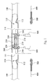
- Fig. 1 is a sectional view showing a hidden hydraulic structure of bike disc brake according to one embodiment of the present disclosure.
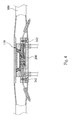
- Fig. 2 is a sectional view showing that the hidden hydraulic structure of bike disc brake of Fig. 1 being assembled.
- a hidden hydraulic structure of bike disc brake includes two bike body tubes 100, a base 200, two pistons 300, two linking members 400, two oil tubes 500 and two disc braking units 600.
- the two bike body tubes 100 are handlebar tubes.
- An accommodating space 110 is openly formed on two opposite sides of the two bike body tubes 100.
- the accommodating space 110 includes an opening 111 and a through hole 112.
- the opening 111 is opened outward.
- the through hole 112 is inclined outward.
- the two openings 111 are disposed oppositely and have the same shapes. It should be mentioned that the shapes of the two openings 111 can be different. For example, one of the openings 111 can be a square and the other of the openings 111 can be a circle.
- the shape of the base 200 is corresponded to the two bike body tubes 100, and the base 200 is connected with the bike body tubes 100.
- Two oil circuits 210, one oil tank 220 and two piston channels 230 are disposed in the base 200.
- Two positioning portions 240 are disposed in two ends of the base 200 respectively, and the shapes of the two positioning portions 240 are corresponded to the two openings 111.
- the base 200 is positioned and is firmly connected in the two openings 111 of the bike body tube 100, thus the base 200 is partially hidden in the accommodating space 110.
- Two pistons 300 are slidably disposed in the two piston channels 230 in the base 200 respectively.
- the two pistons 300 are used for controlling pressures of the two oil circuits 210 respectively.
- each of the linking members 400 passed through the through hole 112 and is dived into the bike body tube 100.
- the two linking members 400 are connected to the two pistons 300, and the two linking members 400 actuate the two pistons 300 to slide.
- the other end of each of the linking members 400 is stretched out from the bike body tube 100 (here connecting the linking member 400 to a controlling handle to form a brake is a known art, there is no repeated herein again).
- each of the two oil tubes 500 is assembled to the base 200, and the two oil tubes 500 are connected to the two oil circuits 210 respectively.
- Two disc braking unit 600 are connected to the other end of the oil tubes 500 respectively.
- One of the disc braking units 600 is disposed in a front wheel of the bike, and the other of the disc braking units 600 is disposed in a rear wheel of the bike.
- the brake of the disc braking units 600 are controlled by the pressures of the two oil tubes 500.
- a controlling handle (not shown) is used to control each of the linking members 400 in order to change the pressure of the oil tube 500.
- the shape and the appearance of the base 200 is corresponded to the two bike body tubes 100, and the base 200 is positioned in the two openings 111 of the bike body tubes 100 by the two positioning portions 240, thus the base 200 is partially hidden in the accommodating space 110. Furthermore, the through hole 112 is for dividing the two linking members 400 into the two bike body tubes 100. Therefore, the base 200 can be firmly positioned in the accommodating space 110, and the accommodating space 110 hiding the base 200 and the two linking members 400 in the middle of the two bike body tubes 100 (the shape or the appearance is not protruded). Compared with the conventional protruded hydraulic structure of bike disc brake, the base 200 and the two linking members 400 of the present discourse can be hidden totally. Therefore, the windage can be eliminated, and the influences on the appearance and the weight of the bike can also be reduced.
- Fig. 3A is a sectional view showing a hidden hydraulic structure of bike disc brake according to another embodiment of the present disclosure.
- Fig 3B is a sectional view showing another sample of the hidden hydraulic structure of bike disc brake of Fig. 3A .
- Fig. 4 is a sectional view showing that the hidden hydraulic structure of bike disc brake of Fig. 3A being assembled.
- a hidden hydraulic structure of bike disc brake includes a bike body tube 100, a base 200, two pistons 300, two linking members 400, two oil tubes 500 and two disc braking units (not shown).
- the integrated bike body tube 100 in this embodiment is a handlebar tube.
- An accommodating space 110 is openly formed in the middle portion of the bike body tube 100.
- the accommodating space 110 includes an opening 111 and two through holes 112.
- the opening 111 is opened outward.
- the two through holes 112 are formed in two inner-sides of the accommodating space 110 and are inclined outward.
- Two screw bases 113 are formed in the opening 111 of the bike body tube 100.
- the appearance and the shape of the base 200 are corresponded to the surfaces of the two bike body tubes 100, and the base 200 is connected with the bike body tubes 100.
- Two positioning portions 240 are disposed in two ends of the base 200 respectively, and the shapes of the base 200 are corresponded to the two openings 111.
- Each of the two positioning portions 240 has a lock hole 241 respectively.
- the base 200 is screwed to the two screw bases 113 by two screws 242. Therefore, the base 200 is positioned in the opening 111 of the bike body tube 100, thus the base 200 can be hidden in the accommodating space 110.
- the oil circuit, oil tank, piston channel, piston 300, linking member 400, oil tube 500 and disc braking unit are similar to the aforementioned embodiment, there is no repeated herein again.
- an integrated bike body tube 100 is cooperated with screwing technology to hide the base 200 into the accommodating space 110. Therefore, the windage can be eliminated, and the appearance of the whole bike will not be influenced. Furthermore, the base 200 can be modularized, thereby achieving easy assembling, disassembling, or replacing. Furthermore, in one example, as shown in Fig. 3B , the linking member 400 can be totally hidden in the bike body tube, therefore it is convenient for installing, and the linking member 400 will not be exposed out.
- Fig. 5 is a sectional view showing that the hidden hydraulic structure of bike disc brake being disposed in a head tube according to one embodiment of the present disclosure
- Fig. 6 is a perspective view showing that the hidden hydraulic structure of bike disc brake being disposed in a bar end tube according to one embodiment of the present disclosure
- Fig. 7 is a perspective view showing that the hidden hydraulic structure of bike disc brake being disposed in a bar end tube in a handlebar tube according to one embodiment of the present disclosure
- Fig. 8 is a perspective view showing that the hidden hydraulic structure of bike disc brake being disposed in a front fork tube according to one embodiment of the present disclosure
- Fig. 9 is a perspective view showing that the hidden hydraulic structure of bike disc brake being disposed in a down tube and a top tube according to one embodiment of the present disclosure.
- a base 200 is screwed in a head tube 710 of the bike.
- one base 200 is corresponded to one piston 300. That is, another base 200 is required and is disposed in another part of the bike, and the disc barking unit in the front wheel and the rear wheel can be controlled by the two bases 200 respectively. It should be mentioned that if one base 200 having two pistons (now shown), and only one base 200 is required for controlling the disc braking units in the front wheel and the rear wheel of the bike.
- the base 200 can be disposed in a bar end tube 720 or the bar end seat 721. Therefore, the base 200 can be disposed in the aforementioned two positions for controlling the disc braking units in the front wheel and the rear wheel respectively.
- one base 200 is also corresponded to one piston, and two bases 200 are disposed in a curve handlebar 730 respectively.
- two bases 200 are disposed in a front fork 740 of the bike for controlling the disc braking units in the front wheel and the rear wheel respectively.
- one base 200 is disposed in a down tube 750 of the bike, and another base 200 is disposed in a top tube 760 of the bike.
- the two bases 200 are disposed closely to the front wheel and the rear wheel respectively, thereby being capable of easily controlling the disc braking units in the front wheel and the rear wheel.
- the base 200 can also be disposed in another bike body tubes, such as a rear tray tube (can be a chain stay tube or a rear stay tube) or a stem tube, etc.
- a rear tray tube can be a chain stay tube or a rear stay tube
- a stem tube etc.
- the hidden hydraulic structure of bike disc brake of the present disclosure can be integrated with the bike body tube in various types.
- the hidden hydraulic structure of bike disc brake can be connected with the bike body tube to form a portion of the bike body tube, the hidden hydraulic structure of bike disc brake can be hidden in the bike body tube, or the members of the hidden hydraulic structure of bike disc brake can be disposed in different bike body tubes. Accordingly, some parts or the total structure of the hidden hydraulic structure of bike disc brake can be hiddenly disposed in the bike body tube, and the hidden hydraulic structure of bike disc brake is not protruded out from the bike. Therefore, the windage can be eliminated, and the hidden hydraulic structure of bike disc brake of the present disclosure can be prevented from being broken or contaminated.
- the linking member can directly connect to the piston, and also directly actuates the piston; therefore, the installing process of the parts can be simplified, and the manufacturing cost can be reduced.
- the base can fully fill a surface of the accommodating space, thus the hidden hydraulic structure of bike disc brake can be fully integrated with the bike body tube, thereby increasing strength of the bike body tube.
Landscapes
- Engineering & Computer Science (AREA)
- Mechanical Engineering (AREA)
- Physics & Mathematics (AREA)
- Fluid Mechanics (AREA)
- Transportation (AREA)
- Transmission Of Braking Force In Braking Systems (AREA)
- Motorcycle And Bicycle Frame (AREA)
- Steering Devices For Bicycles And Motorcycles (AREA)
Abstract
Description
- The present disclosure relates to a hydraulic structure of a vehicle. More particularly, the present disclosure relates to a hidden hydraulic structure of a bike disc brake.
- Bike has been a popular energy-smart product worldwide. The market of the bike has been wide expanded due to bike's advantages on sporty, energy conservation and functionalities on walk-substituting. In this situation, hydraulic bike disc brake having better braking effect has been reached to the market. Compared with the conventional mechanical bike disc brake, the hydraulic bike disc brake has advantages on stable braking power and high power transmitting efficiency, etc. Therefore, the hydraulic bike disc brake has been a representative of the high-end bikes.
- Conventionally, the hydraulic bike disc brake has two types: full- hydraulic bike disc brake and half-hydraulic bike disc brake. When the half-hydraulic bike disc brake is disposed on the bike, in addition to that a disc brake and a hydraulic clamp must be disposed in the wheel; another set of hydraulic structure must be firmly disposed to the bike body. Moreover, brake cables must be connected to the piston in the hydraulic structure, and then a pressure from the hydraulic structure can be transmitted to the hydraulic clamp to produce a brake effect. This type of hydraulic structure of bike disc brake is commonly protruded from the bike body, thereby inducing a large windage, a heavy weight and an obtrusive appearance of the bike.
- The full-hydraulic bike disc brake is commonly used in a bike having flat handlebar. If the full-hydraulic bike disc brake is intended to be disposed in a bike having curve handlebar, issues will occur. For example, a hydraulic shift lever is very expensive and few kinds of hydraulic shift levers are available nowadays. For this reason, most of the shift lever uses a mechanical disc brake clamp. If the hydraulic bike disc brake is used, the hydraulic structure having piston must be disposed under a stem tube, thus a larger windage is produced.
- According to one embodiment of the present disclosure, a hidden hydraulic structure of a bike disc brake is provided. The hidden hydraulic structure of the bike disc brake is connected with a bike body tube. The hidden hydraulic structure of bike disc brake includes a base, a piston and a linking member. The base includes an oil circuit. The piston is disposed in the base for controlling a pressure of the oil circuit. The piston is connected to the linking member and is actuated by the linking member. Wherein a shape of the base is corresponded to a shape of the bike body tube, and the base is connected with the bike body tube to form a portion of the bike body tube, thereby increasing strength of the bike body tube.
- In the aforementioned embodiment, the bike body tube can include an accommodating space, and the base can be detachably disposed in the accommodating space. The accommodating space can be close or open. The hidden hydraulic structure of the bike disc brake can further include a controlling handle for connecting and controlling the linking member.
- According to one embodiment, the bike body tube has an accommodating space. The base is connected to the bike body tube, wherein the base includes at least one positioning portion, and the positioning portion of the base is positioned in the accommodating space. The base can fully fill a surface of the accommodating space for increasing strength of the bike body tube.
- In the aforementioned embodiment, the accommodating space can be close or open. The accommodating space can have a screw base, the positioning portion can have a lock hole, and a screw is passed through the lock hole and is screwed to the screw base. The bike body tube can be a head tube, a handlebar tube, a bar end tube, a stem tube, a top tube, a middle tube, a down tube, a front fork tube or a rear stay tube.
- In the aforementioned embodiment, the hidden hydraulic structure of bike disc brake can include two oil circuits, two positions, two linking members, two oil tubes and two disc braking units. The two oil circuits are disposed in the base. The two pistons are disposed in the base for controlling the pressures of the two oil circuits respectively. The two linking members can be directly connected to the two pistons, and the two linking members actuate the two pistons respectively. The two oil tubes are connected to the two oil circuits respectively and the two disc braking units are connected to the two oil tubes respectively, and the two disc braking units are for braking a front wheel and a rear wheel respectively.
- In the aforementioned example, the two bike body tubes can have two opposite openings, and two accommodating spaces are located in the two opening respectively; and the base is connected between the two openings.
- According to one embodiment, the base is connected to the bike body tube, and the base includes at least one positioning portion, and the positioning portion of the base is positioned in the accommodating space. The base can fully fill a surface of the accommodating space for increasing strength of the bike body tube. The piston is disposed in the base for controlling a pressure of the oil circuit. The linking member connects to the piston, and the linking member actuates the piston. The hidden hydraulic structure of a bike disc brake can further include a controlling handle for connecting and controlling the linking member.
- In the aforementioned embodiment, the accommodating space can be close or open. The accommodating space can have a screw base, the positioning portion can have a lock hole, and a screw is passed through the lock hole and is screwed to the screw base.
- In the aforementioned embodiment, the hidden hydraulic structure of bike disc brake can include two oil circuits, two positions, two linking members, two oil tubes and two disc braking units. The two oil circuits are disposed in the base; the two pistons are disposed in the base for controlling the pressures of the two oil circuits respectively; the two linking member are directly connected to the two pistons, and the two linking members actuate the two pistons respectively; the two oil tubes are connected to the two oil circuits respectively; the two disc braking units are connected to the two oil tubes respectively, and the two disc braking units are for braking a front wheel and a rear wheel of respectively.
- The present disclosure can be more fully understood by reading the following detailed description of the embodiment, with reference made to the accompanying drawings as follows:
-
Fig. 1 is a sectional view showing a hidden hydraulic structure of bike disc brake according to one embodiment of the present disclosure; -
Fig. 2 is a sectional view showing that the hidden hydraulic structure of bike disc brake ofFig. 1 being assembled; -
Fig. 3A is a sectional view showing a hidden hydraulic structure of bike disc brake according to another embodiment of the present disclosure; -
Fig 3B is a sectional view showing another sample of the hidden hydraulic structure of bike disc brake ofFig. 3A ; -
Fig. 4 is a sectional view showing that the hidden hydraulic structure of bike disc brake ofFig. 3A being assembled; -
Fig. 5 is a sectional view showing that the hidden hydraulic structure of bike disc brake being disposed in a head tube according to one embodiment of the present disclosure; -
Fig. 6 is a perspective view showing that the hidden hydraulic structure of bike disc brake being disposed in a bar end tube according to one embodiment of the present disclosure; -
Fig. 7 is a perspective view showing that the hidden hydraulic structure of bike disc brake being disposed in a bar end tube in a handlebar tube according to one embodiment of the present disclosure; -
Fig. 8 is a perspective view showing that the hidden hydraulic structure of bike disc brake being disposed in a front fork tube according to one embodiment of the present disclosure; and -
Fig. 9 is a perspective view showing that the hidden hydraulic structure of bike disc brake being disposed in a down tube and a top tube according to one embodiment of the present disclosure. - Reference will now be made in detail to the present embodiments of the disclosure, examples of which are illustrated in the accompanying drawings. Wherever possible, the same reference numbers are used in the drawings and the description to refer to the same or like parts.
- The present disclosure provides a hidden hydraulic structure of bike disc brake. Parts of the hidden hydraulic structure of bike disc brake can be hidden in a bike body tube, therefore the windage can be eliminated, the weight of the bike can be reduced, and the obtrusive appearance of the bike can be reduced.
-
Fig. 1 is a sectional view showing a hidden hydraulic structure of bike disc brake according to one embodiment of the present disclosure.Fig. 2 is a sectional view showing that the hidden hydraulic structure of bike disc brake ofFig. 1 being assembled. A hidden hydraulic structure of bike disc brake includes twobike body tubes 100, abase 200, twopistons 300, two linkingmembers 400, twooil tubes 500 and twodisc braking units 600. - In
Fig. 1 , the twobike body tubes 100 are handlebar tubes. Anaccommodating space 110 is openly formed on two opposite sides of the twobike body tubes 100. Theaccommodating space 110 includes anopening 111 and a throughhole 112. Theopening 111 is opened outward. The throughhole 112 is inclined outward. The twoopenings 111 are disposed oppositely and have the same shapes. It should be mentioned that the shapes of the twoopenings 111 can be different. For example, one of theopenings 111 can be a square and the other of theopenings 111 can be a circle. - The shape of the
base 200 is corresponded to the twobike body tubes 100, and thebase 200 is connected with thebike body tubes 100. Twooil circuits 210, oneoil tank 220 and twopiston channels 230 are disposed in thebase 200. Two positioningportions 240 are disposed in two ends of the base 200 respectively, and the shapes of the twopositioning portions 240 are corresponded to the twoopenings 111. Thebase 200 is positioned and is firmly connected in the twoopenings 111 of thebike body tube 100, thus thebase 200 is partially hidden in theaccommodating space 110. - Two
pistons 300 are slidably disposed in the twopiston channels 230 in the base 200 respectively. The twopistons 300 are used for controlling pressures of the twooil circuits 210 respectively. - One end of each of the linking
members 400 passed through the throughhole 112 and is dived into thebike body tube 100. The two linkingmembers 400 are connected to the twopistons 300, and the two linkingmembers 400 actuate the twopistons 300 to slide. The other end of each of the linkingmembers 400 is stretched out from the bike body tube 100 (here connecting the linkingmember 400 to a controlling handle to form a brake is a known art, there is no repeated herein again). - One end of each of the two
oil tubes 500 is assembled to thebase 200, and the twooil tubes 500 are connected to the twooil circuits 210 respectively. - Two
disc braking unit 600 are connected to the other end of theoil tubes 500 respectively. One of thedisc braking units 600 is disposed in a front wheel of the bike, and the other of thedisc braking units 600 is disposed in a rear wheel of the bike. The brake of thedisc braking units 600 are controlled by the pressures of the twooil tubes 500. A controlling handle (not shown) is used to control each of the linkingmembers 400 in order to change the pressure of theoil tube 500. - In the aforementioned embodiment, the shape and the appearance of the
base 200 is corresponded to the twobike body tubes 100, and thebase 200 is positioned in the twoopenings 111 of thebike body tubes 100 by the twopositioning portions 240, thus thebase 200 is partially hidden in theaccommodating space 110. Furthermore, the throughhole 112 is for dividing the two linkingmembers 400 into the twobike body tubes 100. Therefore, the base 200 can be firmly positioned in theaccommodating space 110, and theaccommodating space 110 hiding thebase 200 and the two linkingmembers 400 in the middle of the two bike body tubes 100 (the shape or the appearance is not protruded). Compared with the conventional protruded hydraulic structure of bike disc brake, thebase 200 and the two linkingmembers 400 of the present discourse can be hidden totally. Therefore, the windage can be eliminated, and the influences on the appearance and the weight of the bike can also be reduced. -
Fig. 3A is a sectional view showing a hidden hydraulic structure of bike disc brake according to another embodiment of the present disclosure.Fig 3B is a sectional view showing another sample of the hidden hydraulic structure of bike disc brake ofFig. 3A .Fig. 4 is a sectional view showing that the hidden hydraulic structure of bike disc brake ofFig. 3A being assembled. In the embodiment, a hidden hydraulic structure of bike disc brake includes abike body tube 100, abase 200, twopistons 300, two linkingmembers 400, twooil tubes 500 and two disc braking units (not shown). - The integrated
bike body tube 100 in this embodiment is a handlebar tube. Anaccommodating space 110 is openly formed in the middle portion of thebike body tube 100. Theaccommodating space 110 includes anopening 111 and two throughholes 112. Theopening 111 is opened outward. The two throughholes 112 are formed in two inner-sides of theaccommodating space 110 and are inclined outward. Twoscrew bases 113 are formed in theopening 111 of thebike body tube 100. - The appearance and the shape of the base 200 are corresponded to the surfaces of the two
bike body tubes 100, and thebase 200 is connected with thebike body tubes 100. Two positioningportions 240 are disposed in two ends of the base 200 respectively, and the shapes of the base 200 are corresponded to the twoopenings 111. Each of the twopositioning portions 240 has alock hole 241 respectively. Thebase 200 is screwed to the twoscrew bases 113 by twoscrews 242. Therefore, thebase 200 is positioned in theopening 111 of thebike body tube 100, thus the base 200 can be hidden in theaccommodating space 110. In the embodiment, the oil circuit, oil tank, piston channel,piston 300, linkingmember 400,oil tube 500 and disc braking unit are similar to the aforementioned embodiment, there is no repeated herein again. - In this embodiment, an integrated
bike body tube 100 is cooperated with screwing technology to hide the base 200 into theaccommodating space 110. Therefore, the windage can be eliminated, and the appearance of the whole bike will not be influenced. Furthermore, the base 200 can be modularized, thereby achieving easy assembling, disassembling, or replacing. Furthermore, in one example, as shown inFig. 3B , the linkingmember 400 can be totally hidden in the bike body tube, therefore it is convenient for installing, and the linkingmember 400 will not be exposed out. - In the followed embodiments, examples for assembling the base 200 into another part of the bike are shown. Referring to
Figs. 5-9 ,Fig. 5 is a sectional view showing that the hidden hydraulic structure of bike disc brake being disposed in a head tube according to one embodiment of the present disclosure;Fig. 6 is a perspective view showing that the hidden hydraulic structure of bike disc brake being disposed in a bar end tube according to one embodiment of the present disclosure;Fig. 7 is a perspective view showing that the hidden hydraulic structure of bike disc brake being disposed in a bar end tube in a handlebar tube according to one embodiment of the present disclosure;Fig. 8 is a perspective view showing that the hidden hydraulic structure of bike disc brake being disposed in a front fork tube according to one embodiment of the present disclosure; andFig. 9 is a perspective view showing that the hidden hydraulic structure of bike disc brake being disposed in a down tube and a top tube according to one embodiment of the present disclosure. - In
Fig. 5 , abase 200 is screwed in ahead tube 710 of the bike. InFig. 5 , onebase 200 is corresponded to onepiston 300. That is, anotherbase 200 is required and is disposed in another part of the bike, and the disc barking unit in the front wheel and the rear wheel can be controlled by the twobases 200 respectively. It should be mentioned that if onebase 200 having two pistons (now shown), and only onebase 200 is required for controlling the disc braking units in the front wheel and the rear wheel of the bike. - In
Fig. 6 , the base 200 can be disposed in abar end tube 720 or thebar end seat 721. Therefore, the base 200 can be disposed in the aforementioned two positions for controlling the disc braking units in the front wheel and the rear wheel respectively. - In
Fig. 7 , onebase 200 is also corresponded to one piston, and twobases 200 are disposed in acurve handlebar 730 respectively. - In
Fig. 8 , twobases 200 are disposed in afront fork 740 of the bike for controlling the disc braking units in the front wheel and the rear wheel respectively. - In
Fig. 9 , onebase 200 is disposed in adown tube 750 of the bike, and anotherbase 200 is disposed in atop tube 760 of the bike. InFig. 9 , the twobases 200 are disposed closely to the front wheel and the rear wheel respectively, thereby being capable of easily controlling the disc braking units in the front wheel and the rear wheel. - It should be mentioned that the base 200 can also be disposed in another bike body tubes, such as a rear tray tube (can be a chain stay tube or a rear stay tube) or a stem tube, etc.
- In sum up, the hidden hydraulic structure of bike disc brake of the present disclosure can be integrated with the bike body tube in various types. For example, the hidden hydraulic structure of bike disc brake can be connected with the bike body tube to form a portion of the bike body tube, the hidden hydraulic structure of bike disc brake can be hidden in the bike body tube, or the members of the hidden hydraulic structure of bike disc brake can be disposed in different bike body tubes. Accordingly, some parts or the total structure of the hidden hydraulic structure of bike disc brake can be hiddenly disposed in the bike body tube, and the hidden hydraulic structure of bike disc brake is not protruded out from the bike. Therefore, the windage can be eliminated, and the hidden hydraulic structure of bike disc brake of the present disclosure can be prevented from being broken or contaminated. Furthermore, the linking member can directly connect to the piston, and also directly actuates the piston; therefore, the installing process of the parts can be simplified, and the manufacturing cost can be reduced. The base can fully fill a surface of the accommodating space, thus the hidden hydraulic structure of bike disc brake can be fully integrated with the bike body tube, thereby increasing strength of the bike body tube.
- Although the present disclosure has been described in considerable detail with reference to certain embodiments thereof, other embodiments are possible. Therefore, the spirit and scope of the appended claims should not be limited to the description of the embodiments contained herein.
- It will be apparent to those skilled in the art that various modifications and variations can be made to the structure of the present disclosure without departing from the scope or spirit of the disclosure. In view of the foregoing, it is intended that the present disclosure cover modifications and variations of this disclosure provided they fall within the scope of the following claims.
Claims (15)
- A hidden hydraulic structure of a bike disc brake connected with a bike body tube (100), the hidden hydraulic structure of the bike disc brake comprising a base (200), a piston (300) and a linking member (400); wherein the base (200) comprises an oil circuit (210), the piston (300) is disposed in the base (200) for controlling a pressure of the oil circuit (210), the piston (300) is connected to the linking member (400) and actuated by the linking member (400);
wherein a shape of the base (200) is corresponded to a shape of the bike body tube (100), and the base (200) is connected with the bike body tube (100) to form a portion of the bike body tube (100), thereby increasing strength of the bike body tube (100). - The hidden hydraulic structure of the bike disc brake of claim 1, wherein the bike body tube (100) comprises an accommodating space (110), and the base (200) is detachably disposed in the accommodating space (110); and the liking member (400) directly connects to the piston (300) and actuates the piston (300).
- The hidden hydraulic structure of the bike disc brake of claim 2, wherein the accommodating space (110) is close or open.
- The hidden hydraulic structure of the bike disc brake of claim 1, wherein the bike body tube (100) is a head tube (710), a handlebar tube, a bar end tube, a stem tube, a top tube, a middle tube, a down tube, a front fork tube or a rear stay tube.
- The hidden hydraulic structure of the bike disc brake of claim 1, further comprising a controlling handle connecting and controlling the linking member (400).
- The hidden hydraulic structure of the bike disc brake of claim 1, wherein:the bike body tube (100) has an accommodating space (110);the base (200) is connected to the bike body tube (100), wherein the base (200) comprises at least one positioning portion (240), and the positioning portion (240) of the base (200) is positioned in the accommodating space (110), and the base (200) fully fills a surface of the accommodating space (110) for increasing strength of the bike body tube (100).
- The hidden hydraulic structure of the bike disc brake of claim 6, wherein the accommodating space (110) is close or open.
- The hidden hydraulic structure of the bike disc brake of claim 6, wherein the accommodating space (110) has a screw base (113), the positioning portion (240) has a lock hole (241), and a screw (242) is passed through the lock hole (241) and is screwed to the screw base (113).
- The hidden hydraulic structure of the bike disc brake of claim 6, wherein the bike body tube (100) is a head tube (710), a handlebar tube, a bar end tube, a stem tube, a top tube, a middle tube, a down tube, a front fork tube or a rear stay tube.
- The hidden hydraulic structure of the bike disc brake of claim 6, wherein,
two oil circuits (210) are disposed in the base (200);
two pistons (300) are disposed in the base (200) for controlling the pressures of the two oil circuits (210) respectively;
two linking members (400) are directly connected to the two pistons (300), and the two linking members (400) actuate the two pistons (300) respectively;
two oil tubes (500) are connected to the two oil circuits (210) respectively; and two disc braking units (600) are connected to the two oil tubes (500) respectively, and the two disc braking units (600) are for braking a front wheel and a rear wheel respectively. - The hidden hydraulic structure of the bike disc brake of claim 6, wherein,
two bike body tubes (100) have two opposite openings (111), and two accommodating spaces (110) are located in the two openings (111) respectively; and
the base (200) is connected between the two openings (111). - The hidden hydraulic structure of the bike disc brake of claim 1, wherein:the bike body tube (100) has an accommodating space (110);the base (200) is connected to the bike body tube (100), wherein the base (200) comprises at least one positioning portion (240), and the positioning portion (240) of the base is positioned in the accommodating space (110), the base (200) fully fills a surface of the accommodating space (110) for increasing strength of the bike body tube (100); and a controlling handle connecting and controlling the linking member (400).
- The hidden hydraulic structure of the bike disc brake of claim 12, wherein the accommodating space (110) is close or open.
- The hidden hydraulic structure of the bike disc brake of claim 12, wherein the accommodating space (110) has a screw base (113), the positioning portion (240) has a lock hole (241), and a screw (242) is passed through the lock hole (241) and is screwed to the screw base (113).
- The hidden hydraulic structure of the bike disc brake of claim 12, wherein,
two oil circuits (210) are disposed in the base (200);
two pistons (300) are disposed in the base (200) for controlling the pressures of the two oil circuits (210) respectively;
two linking members (400) are directly connected to the two pistons (300), and the two linking members (400) actuate the two pistons (300) respectively;
two oil tubes (500) are connected to the two oil circuits (210) respectively; and two disc braking units (600) are connected to the two oil tubes (500) respectively, and the two disc braking units (600) are for braking a front wheel and a rear wheel of respectively.
Applications Claiming Priority (1)
| Application Number | Priority Date | Filing Date | Title |
|---|---|---|---|
| TW103202074U TWM485200U (en) | 2014-01-29 | 2014-01-29 | Bicycle hydraulic disc hidden hydraulic mechanism |
Publications (2)
| Publication Number | Publication Date |
|---|---|
| EP2902282A1 true EP2902282A1 (en) | 2015-08-05 |
| EP2902282B1 EP2902282B1 (en) | 2026-04-08 |
Family
ID=51943954
Family Applications (1)
| Application Number | Title | Priority Date | Filing Date |
|---|---|---|---|
| EP15152578.9A Active EP2902282B1 (en) | 2014-01-29 | 2015-01-27 | Structure set including hidden hydraulic structure of bike disc brake and handlebar tubes |
Country Status (7)
| Country | Link |
|---|---|
| US (1) | US9573650B2 (en) |
| EP (1) | EP2902282B1 (en) |
| JP (1) | JP6077575B2 (en) |
| CN (1) | CN204623736U (en) |
| AU (1) | AU2015100088A4 (en) |
| CA (1) | CA2880698C (en) |
| TW (1) | TWM485200U (en) |
Families Citing this family (13)
| Publication number | Priority date | Publication date | Assignee | Title |
|---|---|---|---|---|
| US9937977B2 (en) * | 2014-04-09 | 2018-04-10 | Shimano Inc. | Bicycle operating system, take-up device, and bicycle operating apparatus |
| CN105882859A (en) * | 2015-01-19 | 2016-08-24 | 张小红 | Closed type adjustable oil brake upper pump |
| TWI565619B (en) * | 2015-03-19 | 2017-01-11 | 彥豪金屬工業股份有限公司 | A front fork structure for a bicycle |
| TWM522177U (en) * | 2015-11-13 | 2016-05-21 | 巨大機械工業股份有限公司 | Bicycle hydraulic pressure plate device |
| ITUB20156263A1 (en) | 2015-12-03 | 2017-06-03 | Campagnolo Srl | Hub for a bicycle wheel |
| ITUB20156265A1 (en) * | 2015-12-04 | 2017-06-04 | Campagnolo Srl | Method of mounting a hydraulic brake system on a bicycle, hydraulic braking system and assembly tool |
| ITUA20161804A1 (en) * | 2016-03-18 | 2017-09-18 | Campagnolo Srl | Caliper assembly of a bicycle disc brake and method for mounting a caliper assembly on a bicycle carrier |
| CN106005210B (en) * | 2016-07-18 | 2019-01-04 | 宁波彰星车辆有限公司 | A kind of bicycle brake safety governor |
| DE102017211793A1 (en) | 2017-07-10 | 2019-01-10 | Gustav Magenwirth Gmbh & Co. Kg | Hydraulic line connection for a hydraulic brake handlebar guided vehicles, hydraulic line connection and hydraulic component fixing device for a hydraulic actuator handlebar guided vehicles, handlebar assembly for a handlebar-guided vehicle and hydraulic brake for a handlebar-guided vehicle |
| CN110857133A (en) * | 2018-08-22 | 2020-03-03 | 彦豪金属工业股份有限公司 | Headset assembly with anti-brake locking device |
| TWI728739B (en) * | 2020-03-11 | 2021-05-21 | 彥豪金屬工業股份有限公司 | Bicycle brake system, bicycle handlebar assembly, and connector thereof |
| GB2630949A (en) * | 2023-06-13 | 2024-12-18 | Karbon Kinetics Ltd | Bicycle handlebar with inboard master cylinder |
| WO2025157236A1 (en) * | 2024-01-25 | 2025-07-31 | 兰溪市捷克运动器材制造有限公司 | Cable-driven hydraulic conversion pump, handlebar and two-wheeled vehicle |
Citations (4)
| Publication number | Priority date | Publication date | Assignee | Title |
|---|---|---|---|---|
| US20070209885A1 (en) * | 2003-02-20 | 2007-09-13 | Formula S.R.L. | Apparatus for the control of brakes in bicycles and the like |
| CN101468705A (en) * | 2007-12-27 | 2009-07-01 | 彦豪金属工业股份有限公司 | Concealed oil pumping device for bicycle hydraulic brake |
| CN201999156U (en) * | 2011-03-09 | 2011-10-05 | 彦豪金属工业股份有限公司 | Hidden hydraulic cylinder brake device |
| US20130240313A1 (en) * | 2010-10-19 | 2013-09-19 | Wayne-Ian Moore | Hydraulic brake system |
Family Cites Families (6)
| Publication number | Priority date | Publication date | Assignee | Title |
|---|---|---|---|---|
| JP3147178B2 (en) * | 1991-04-25 | 2001-03-19 | 富士電機株式会社 | Circuit breaker |
| IT1291293B1 (en) | 1997-04-30 | 1999-01-07 | Riva Calzoni Spa | HYDRAULIC UNIT FOR ACTUATING BRAKES/CLUTCHES OR SIMILAR INSIDE THE HANDLEBAR OF A MOTORCYCLE OR SIMILAR |
| US5950772A (en) * | 1997-08-29 | 1999-09-14 | Hayes Brake, Inc. | Bicycle brake system having a flexible disk |
| JP3147178U (en) | 2008-10-07 | 2008-12-18 | 彦豪金属工業股▲分▼有限公司 | Bicycle hydraulic disc brake clip structure |
| TWI381974B (en) | 2010-01-06 | 2013-01-11 | Ashima Ltd | A device that can be equipped with a hydraulic brake |
| US20120241261A1 (en) * | 2011-03-24 | 2012-09-27 | Tektro Technology Corporation | Semi-hydraulic bake for bicycle |
-
2014
- 2014-01-29 TW TW103202074U patent/TWM485200U/en not_active IP Right Cessation
-
2015
- 2015-01-26 CN CN201520052773.4U patent/CN204623736U/en not_active Expired - Lifetime
- 2015-01-26 US US14/605,984 patent/US9573650B2/en active Active
- 2015-01-27 JP JP2015013444A patent/JP6077575B2/en active Active
- 2015-01-27 AU AU2015100088A patent/AU2015100088A4/en not_active Expired
- 2015-01-27 CA CA2880698A patent/CA2880698C/en active Active
- 2015-01-27 EP EP15152578.9A patent/EP2902282B1/en active Active
Patent Citations (4)
| Publication number | Priority date | Publication date | Assignee | Title |
|---|---|---|---|---|
| US20070209885A1 (en) * | 2003-02-20 | 2007-09-13 | Formula S.R.L. | Apparatus for the control of brakes in bicycles and the like |
| CN101468705A (en) * | 2007-12-27 | 2009-07-01 | 彦豪金属工业股份有限公司 | Concealed oil pumping device for bicycle hydraulic brake |
| US20130240313A1 (en) * | 2010-10-19 | 2013-09-19 | Wayne-Ian Moore | Hydraulic brake system |
| CN201999156U (en) * | 2011-03-09 | 2011-10-05 | 彦豪金属工业股份有限公司 | Hidden hydraulic cylinder brake device |
Also Published As
| Publication number | Publication date |
|---|---|
| CA2880698A1 (en) | 2015-04-02 |
| CN204623736U (en) | 2015-09-09 |
| CA2880698C (en) | 2017-11-28 |
| US20150210347A1 (en) | 2015-07-30 |
| JP2015140180A (en) | 2015-08-03 |
| TWM485200U (en) | 2014-09-01 |
| US9573650B2 (en) | 2017-02-21 |
| JP6077575B2 (en) | 2017-02-08 |
| AU2015100088A4 (en) | 2015-02-26 |
| EP2902282B1 (en) | 2026-04-08 |
Similar Documents
| Publication | Publication Date | Title |
|---|---|---|
| EP2902282A1 (en) | Hidden hydraulic structure of bike disc brake | |
| CN103359246B (en) | Bicycle hydraulic part handling apparatus | |
| CN105584575B (en) | Control device for hydraulic brake for bicycle handle bar | |
| CN209904972U (en) | Brake handle of bicycle | |
| US9415831B2 (en) | Bicycle hydraulic operating device | |
| US10589819B2 (en) | Bicycle operating device | |
| US7578375B2 (en) | Hydraulic brake lever | |
| US20130277162A1 (en) | Bicycle hydraulic operating device | |
| US20170036734A1 (en) | Hydraulic Brake Mechanism | |
| US20150284047A1 (en) | Bicycle component fixing structure | |
| US9896150B2 (en) | Bicycle operating device | |
| TWI704076B (en) | Bar-end device assembly for tube member of bicycle | |
| CN104512508A (en) | Bicycle clamp structure and bicycle operating device | |
| US20160272269A1 (en) | Bicycle front fork assembly | |
| CN108082382A (en) | Bicycle hydraulic operating system | |
| US20100218640A1 (en) | Detachable brake lever assembly for a bicycle | |
| CN107878659B (en) | Hydraulic operating device for bicycle | |
| US8888066B2 (en) | Adjustable holder of a hydraulic brake device for a bicycle | |
| US20130139635A1 (en) | Gear-Shifting Mechanism for Vehicles | |
| US10384741B2 (en) | Bicycle hydraulic operating device |
Legal Events
| Date | Code | Title | Description |
|---|---|---|---|
| PUAI | Public reference made under article 153(3) epc to a published international application that has entered the european phase |
Free format text: ORIGINAL CODE: 0009012 |
|
| 17P | Request for examination filed |
Effective date: 20150413 |
|
| AK | Designated contracting states |
Kind code of ref document: A1 Designated state(s): AL AT BE BG CH CY CZ DE DK EE ES FI FR GB GR HR HU IE IS IT LI LT LU LV MC MK MT NL NO PL PT RO RS SE SI SK SM TR |
|
| AX | Request for extension of the european patent |
Extension state: BA ME |
|
| STAA | Information on the status of an ep patent application or granted ep patent |
Free format text: STATUS: EXAMINATION IS IN PROGRESS |
|
| 17Q | First examination report despatched |
Effective date: 20180131 |
|
| GRAP | Despatch of communication of intention to grant a patent |
Free format text: ORIGINAL CODE: EPIDOSNIGR1 |
|
| STAA | Information on the status of an ep patent application or granted ep patent |
Free format text: STATUS: GRANT OF PATENT IS INTENDED |
|
| INTG | Intention to grant announced |
Effective date: 20250918 |
|
| GRAS | Grant fee paid |
Free format text: ORIGINAL CODE: EPIDOSNIGR3 |
|
| GRAJ | Information related to disapproval of communication of intention to grant by the applicant or resumption of examination proceedings by the epo deleted |
Free format text: ORIGINAL CODE: EPIDOSDIGR1 |
|
| GRAL | Information related to payment of fee for publishing/printing deleted |
Free format text: ORIGINAL CODE: EPIDOSDIGR3 |
|
| STAA | Information on the status of an ep patent application or granted ep patent |
Free format text: STATUS: EXAMINATION IS IN PROGRESS |
|
| STAA | Information on the status of an ep patent application or granted ep patent |
Free format text: STATUS: GRANT OF PATENT IS INTENDED |
|
| INTC | Intention to grant announced (deleted) | ||
| GRAA | (expected) grant |
Free format text: ORIGINAL CODE: 0009210 |
|
| STAA | Information on the status of an ep patent application or granted ep patent |
Free format text: STATUS: THE PATENT HAS BEEN GRANTED |
|
| AK | Designated contracting states |
Kind code of ref document: B1 Designated state(s): AL AT BE BG CH CY CZ DE DK EE ES FI FR GB GR HR HU IE IS IT LI LT LU LV MC MK MT NL NO PL PT RO RS SE SI SK SM TR |
|
| REG | Reference to a national code |
Ref country code: CH Ref legal event code: F10 Free format text: ST27 STATUS EVENT CODE: U-0-0-F10-F00 (AS PROVIDED BY THE NATIONAL OFFICE) Effective date: 20260408 Ref country code: GB Ref legal event code: FG4D |
|
| REG | Reference to a national code |
Ref country code: DE Ref legal event code: R096 Ref document number: 602015093221 Country of ref document: DE |