EP2901913A1 - Endoscope device having cleaning mechanism - Google Patents
Endoscope device having cleaning mechanism Download PDFInfo
- Publication number
- EP2901913A1 EP2901913A1 EP13842411.4A EP13842411A EP2901913A1 EP 2901913 A1 EP2901913 A1 EP 2901913A1 EP 13842411 A EP13842411 A EP 13842411A EP 2901913 A1 EP2901913 A1 EP 2901913A1
- Authority
- EP
- European Patent Office
- Prior art keywords
- observation port
- lens
- viewing observation
- cleaning liquid
- viewing
- Prior art date
- Legal status (The legal status is an assumption and is not a legal conclusion. Google has not performed a legal analysis and makes no representation as to the accuracy of the status listed.)
- Withdrawn
Links
Images




Classifications
-
- A—HUMAN NECESSITIES
- A61—MEDICAL OR VETERINARY SCIENCE; HYGIENE
- A61B—DIAGNOSIS; SURGERY; IDENTIFICATION
- A61B1/00—Instruments for performing medical examinations of the interior of cavities or tubes of the body by visual or photographical inspection, e.g. endoscopes; Illuminating arrangements therefor
- A61B1/12—Instruments for performing medical examinations of the interior of cavities or tubes of the body by visual or photographical inspection, e.g. endoscopes; Illuminating arrangements therefor with cooling or rinsing arrangements
- A61B1/126—Instruments for performing medical examinations of the interior of cavities or tubes of the body by visual or photographical inspection, e.g. endoscopes; Illuminating arrangements therefor with cooling or rinsing arrangements provided with means for cleaning in-use
-
- A—HUMAN NECESSITIES
- A61—MEDICAL OR VETERINARY SCIENCE; HYGIENE
- A61B—DIAGNOSIS; SURGERY; IDENTIFICATION
- A61B1/00—Instruments for performing medical examinations of the interior of cavities or tubes of the body by visual or photographical inspection, e.g. endoscopes; Illuminating arrangements therefor
- A61B1/00064—Constructional details of the endoscope body
- A61B1/00071—Insertion part of the endoscope body
- A61B1/0008—Insertion part of the endoscope body characterised by distal tip features
- A61B1/00089—Hoods
-
- A—HUMAN NECESSITIES
- A61—MEDICAL OR VETERINARY SCIENCE; HYGIENE
- A61B—DIAGNOSIS; SURGERY; IDENTIFICATION
- A61B1/00—Instruments for performing medical examinations of the interior of cavities or tubes of the body by visual or photographical inspection, e.g. endoscopes; Illuminating arrangements therefor
- A61B1/00064—Constructional details of the endoscope body
- A61B1/00071—Insertion part of the endoscope body
- A61B1/0008—Insertion part of the endoscope body characterised by distal tip features
- A61B1/00091—Nozzles
-
- A—HUMAN NECESSITIES
- A61—MEDICAL OR VETERINARY SCIENCE; HYGIENE
- A61B—DIAGNOSIS; SURGERY; IDENTIFICATION
- A61B1/00—Instruments for performing medical examinations of the interior of cavities or tubes of the body by visual or photographical inspection, e.g. endoscopes; Illuminating arrangements therefor
- A61B1/00064—Constructional details of the endoscope body
- A61B1/00071—Insertion part of the endoscope body
- A61B1/0008—Insertion part of the endoscope body characterised by distal tip features
- A61B1/00096—Optical elements
-
- A—HUMAN NECESSITIES
- A61—MEDICAL OR VETERINARY SCIENCE; HYGIENE
- A61B—DIAGNOSIS; SURGERY; IDENTIFICATION
- A61B1/00—Instruments for performing medical examinations of the interior of cavities or tubes of the body by visual or photographical inspection, e.g. endoscopes; Illuminating arrangements therefor
- A61B1/00163—Optical arrangements
- A61B1/00174—Optical arrangements characterised by the viewing angles
- A61B1/00177—Optical arrangements characterised by the viewing angles for 90 degrees side-viewing
-
- A—HUMAN NECESSITIES
- A61—MEDICAL OR VETERINARY SCIENCE; HYGIENE
- A61B—DIAGNOSIS; SURGERY; IDENTIFICATION
- A61B1/00—Instruments for performing medical examinations of the interior of cavities or tubes of the body by visual or photographical inspection, e.g. endoscopes; Illuminating arrangements therefor
- A61B1/00163—Optical arrangements
- A61B1/00174—Optical arrangements characterised by the viewing angles
- A61B1/00181—Optical arrangements characterised by the viewing angles for multiple fixed viewing angles
-
- A—HUMAN NECESSITIES
- A61—MEDICAL OR VETERINARY SCIENCE; HYGIENE
- A61B—DIAGNOSIS; SURGERY; IDENTIFICATION
- A61B1/00—Instruments for performing medical examinations of the interior of cavities or tubes of the body by visual or photographical inspection, e.g. endoscopes; Illuminating arrangements therefor
- A61B1/012—Instruments for performing medical examinations of the interior of cavities or tubes of the body by visual or photographical inspection, e.g. endoscopes; Illuminating arrangements therefor characterised by internal passages or accessories therefor
- A61B1/015—Control of fluid supply or evacuation
-
- A—HUMAN NECESSITIES
- A61—MEDICAL OR VETERINARY SCIENCE; HYGIENE
- A61B—DIAGNOSIS; SURGERY; IDENTIFICATION
- A61B1/00—Instruments for performing medical examinations of the interior of cavities or tubes of the body by visual or photographical inspection, e.g. endoscopes; Illuminating arrangements therefor
- A61B1/06—Instruments for performing medical examinations of the interior of cavities or tubes of the body by visual or photographical inspection, e.g. endoscopes; Illuminating arrangements therefor with illuminating arrangements
- A61B1/0625—Instruments for performing medical examinations of the interior of cavities or tubes of the body by visual or photographical inspection, e.g. endoscopes; Illuminating arrangements therefor with illuminating arrangements for multiple fixed illumination angles
-
- G—PHYSICS
- G02—OPTICS
- G02B—OPTICAL ELEMENTS, SYSTEMS OR APPARATUS
- G02B23/00—Telescopes, e.g. binoculars; Periscopes; Instruments for viewing the inside of hollow bodies; Viewfinders; Optical aiming or sighting devices
- G02B23/24—Instruments or systems for viewing the inside of hollow bodies, e.g. fibrescopes
- G02B23/2476—Non-optical details, e.g. housings, mountings, supports
-
- G—PHYSICS
- G02—OPTICS
- G02B—OPTICAL ELEMENTS, SYSTEMS OR APPARATUS
- G02B27/00—Optical systems or apparatus not provided for by any of the groups G02B1/00 - G02B26/00, G02B30/00
- G02B27/0006—Optical systems or apparatus not provided for by any of the groups G02B1/00 - G02B26/00, G02B30/00 with means to keep optical surfaces clean, e.g. by preventing or removing dirt, stains, contamination, condensation
Definitions
- the present invention relates to an endoscopic device including a direct-viewing observation port used to directly view the front, and a side-viewing observation port used to observe the lateral circumference by using a cylindrical lens which are provided at a tip of an insertion part, and provided with a cleaning mechanism configured to clean the observation ports.
- a direct-viewing observation port used to carry out imaging in the insertion direction (axial direction) in a predetermined visual field region, illumination port through which illuminating light for observation is applied, forceps hole used to extend forceps or the like, and so on are arranged on the tip face of an insertion section.
- a large intestine which is the observation object has many folds, and there is the possibility of an oversight occurring unless observations are made carefully by turning the bending part.
- a side-viewing observation port it is possible to make the visual field region wider, and more securely prevent an oversight from occurring.
- an endoscopic device provided with a direct-viewing observation port configured to make direct-viewing observations, and side-viewing observation port configured to make side-viewing observations of the lateral circumference as shown in patent literature 2 is proposed.
- the insertion section of the endoscope is inserted into the body cavity of a patient, and hence a foreign substance remaining in the body cavity adheres to the observation port provided at the tip thereof. Adhesion of the foreign substance to the observation port hinders the observations, and hence as proposed in, for example, patent literature 3, a nozzle is arranged in the vicinity of the observation port, and a gaseous body and/or a liquid body is gushed as the need arises, whereby the foreign substance is removed, and the observation port is cleaned.
- a cylindrical lens structure is conceivable in which a side-viewing observation port is arranged on the tip face in the axial direction, and a direct-viewing observation port is arranged on the front side of the side-viewing observation port to overlay it.
- a nozzle used to wash the direct-viewing observation port is required, and hence a structure configured to arrange a nozzle at a position reaching the height of the direct-viewing observation port should be formed. Furthermore, it is also necessary to arrange a nozzle used to wash the side-viewing observation port.
- the present invention provides an endoscopic device including a direct-viewing observation port, and side-viewing observation port which are provided on a tip face of an insertion section, and provided with a cleaning mechanism configured to clean the observation ports.
- an endoscopic device including a cleaning mechanism characterized by comprising: a cylindrical lens arranged at a tip of an insertion section of an endoscope as an optical member for observation with a face thereof laterally circumferential with respect to an axial direction which is an insertion direction exposed to the outside; a pedestal section two lateral faces of which obliquely and straightly extending toward the central side of the cylindrical lens are joined to the laterally circumferential face, and inside which a liquid-sending route configured to send a cleaning liquid, and a gas-sending route configured to send a gaseous body are internally provided; and two wash nozzles each of which is provided on each of the two lateral faces, and is configured to selectively gush a fluid current obtained by mixing the cleaning liquid, and the gaseous body, only the liquid or only the gaseous body, an angle which gushing directions of the cleaning liquid straightly gushed from the two wash nozzles toward the laterally circumferential faces form with each other is an acute
- an endoscopic device in which a direct-viewing observation port, and side-viewing observation port are provided on the tip face of the insertion section, and which includes a cleaning mechanism configured to clean each of the observation ports.
- FIG. 1 is a view showing the external configuration of an endoscopic device provided with a cleaning mechanism configured to clean an imaging unit including a direct-viewing observation port, and side-viewing observation port according to a first embodiment.
- the endoscopic device of this embodiment is roughly constituted of an endoscope main body 1, and endoscopic apparatus 7 mounted on a movable trolley 2.
- endoscopic apparatus 7 mounted on a movable trolley 2.
- the endoscope main body 1 is constituted of an insertion section (flexible tube) 4 to be inserted into a body cavity which is an observation object, bending section 5 which is provided on the tip side of the insertion section 4, and to which a lens unit to be described later is provided at the tip thereof, and operation section 3 configured to make the bending section 5 carry out a bending operation.
- the bending section 5 side is referred to as the tip side
- the operation section 3 side is referred to as the proximal end side
- the insertion section 4 is regarded as the center.
- the endoscopic apparatus 7 include a light-source unit configured to create illumination light used to illuminate the observation object part, video processor configured to subject an image signal acquired by imaging to predetermined image processing, monitor configured to display an image signal as an observation image, keyboard serving as an input section, and the like.
- a bottle 8 used to retain a liquid (cleaning liquid: for example, a liquid mainly constituted of water such as physiological sodium chloride solution or the like) used for cleaning or the like is detachably attached to a supporting column of the trolley 2. Further, inside the endoscopic apparatus 7, a gas-sending pump unit 34 (see FIG. 3 ) is arranged. Furthermore, on a shelf of the trolley 2, a suction unit 10 configured to suck a liquid or gas gushed into the body cavity from a wash nozzle to be described later in the body cavity is provided.
- a liquid cleaning liquid: for example, a liquid mainly constituted of water such as physiological sodium chloride solution or the like
- the endoscope main body 1, and the light-source unit are connector-connected to each other with a universal cable 6.
- the universal cable 6 includes, in addition to a light guide constituted of an optical fiber, a plurality of signal lines configured to transmit an image signal, and the like, and supply routes (gas-sending/liquid-sending channels) and exhaust routes of a gaseous body and liquid body constituted of tubes.
- a connector of the universal cable 6 configured to connect the cable 6 to the endoscopic apparatus 7 side branches the cable 6 into the signal lines, tubes, and light guide, and connects these branched members to their corresponding configuration parts.
- FIG. 2A is a view showing the external configuration of the insertion section tip.
- FIG. 2B is a view showing the configuration of the insertion section tip viewed from the front.
- FIG. 2C is a view showing a configuration example of a wash nozzle.
- FIG. 3 is a view showing a configuration example of a gas-sending/liquid-sending mechanism of this embodiment.
- FIG. 7 is a view conceptually showing the configuration of the optical system of the imaging section of the endoscope.
- a direction of movement of the insertion section in the body cavity is referred to as an insertion direction or an axial direction
- the face of the insertion section viewed from the axial direction is referred as the front face (tip face)
- the face of the insertion section orthogonality to the axial direction thereof is referred to as a lateral face or a laterally circumferential face.
- pedestal 13 which is a tip structure having a front face flush with the face of the direct-viewing observation port 14 (face having a height identical to the forward-protrusion height of the direct-viewing observation port 14), wash nozzle 16 arranged on the front face side of the pedestal 13 in close proximity to the direct-viewing observation port 14, two wash nozzles 17 arranged on both lateral faces of the pedestal 13, aperture section 19 of a forceps hole used to insert forceps (not shown) or the like, direct-viewing observation port 14 used to carry out imaging in the insertion direction (axial direction) in a predetermined visual field region, and illumination port 18 arranged on the front face of the pedestal 13, and used to apply illumination light for the direct-viewing observation port 14 are arranged.
- the direct-viewing observation port 14 is arranged on the front face when viewed from the axial direction, and the side-viewing observation port 15 is arranged on the rear side (proximal end side) of the port 14.
- the lens unit 11 is a part of the imaging optical system of the endoscope as shown in FIG. 8 , is arranged in front of an imaging element (not shown), and is constituted of a plurality of lenses, and lens groups, and lens frames (12a, 12b) 12 supporting the lenses in order to form a captured image.
- the direct-viewing observation port 14 are constituted of a circular concave lens 41 (first lens), first lens group (42a, 42b) 42, and second lens group (43a, 43b, 43c, 43d, 43e) 43.
- the light flux L1 incident on the direct-viewing observation port 14 passes through the lenses 41, and 42a, is collected at the lens 42b serving as a focal point, then further passes through the second lens group, and is guided to the imaging element (not shown) as a light figure.
- the side-viewing observation port 15 is constituted of a cylindrical lens 42a.
- the cylindrical lens 42a is arranged in such a manner that the lateral face (referred to as a laterally circumferential face) of the circumference thereof is exposed, and is a lens the front side and back side of which are formed into a convex and concave.
- the light flux L2 incident on the laterally circumferential face from the lateral circumference is reflected from the concave, and is directed to the convex side.
- the light flux L2 further reflected from the convex surface passes through the concave, then is collected at the lens 42b serving as a focal point, then passes through the second lens group, and is further guided to the imaging element (not shown) as a light figure.
- the whole or part of the circumferential face corresponding to a place at which the cylindrical lens is exposed to the outside is formed of a light guiding member (translucent member).
- a light guiding member transparent member
- At least part of (not shown) the lens frame 12b guides the illumination light branched from the light guide.
- the guided illumination light is applied as the illumination light in the laterally circumferential direction to illuminate the observation visual field of the side-viewing observation port from each lens frame surface.
- a liquid-sending route, and gas-sending route to be connected to the wash nozzles are formed and, furthermore an optical fiber cable is arranged in order to guide the illumination light to the illumination port 18 arranged on the front face.
- an approximately triangular shape as indicated by alternate long and short dash lines in FIG. 4 is assumed, the part which virtually becomes the base of the triangle becomes the circular arc surface identical to the circumferential surface of the tip of the bending section 5, and the parts which become the oblique sides of the triangle become the two lateral faces directed from both ends of the base to the central part of the direct-viewing observation port 14.
- a perpendicular line vertically passing through the center m of the direct-viewing observation port 14 is assumed, and assuming that the perpendicular line, and the base vertically intersect each other, the virtual intersection point of the two lateral faces is on the perpendicular line. Furthermore, the triangle, and the lens unit 11 overlap each other in such a manner that the crowning part of the triangle including the virtual intersection point of the two lateral faces is positioned within the direct-viewing observation port 14 and, substantially, the pedestal 13 is formed into approximately a fan shape adhering closely to the lens unit 11.
- a wash nozzle 17 is provided on each of the two lateral faces of the pedestal 13.
- a cleaning liquid gushed from the wash nozzle 17 flows in contact with the lateral face of the side-viewing observation port 15, and further flows to go around the top part of the lens unit 11.
- the side-viewing observation port 15 is cleaned by such a liquid current.
- FIG. 2C in each of the wash nozzles 16, and 17, a face thereof facing the observation port is made the aperture face (ejection hole) 20a, and the inside thereof is made hollow.
- an aperture 20b of the gas-sending/liquid-sending route is formed on the pedestal face.
- FIG. 3 is a view showing a configuration example of a gas-sending/liquid-sending mechanism of this embodiment.
- a liquid serving as the cleaning liquid is contained in a bottle 8, and the liquid is sent from the bottle 8 to the endoscope 1 through the tube, connector 9, and universal cable 6.
- a liquid-sending tube (channel) 22, and gas-sending tube 23 are provided, and a confluence section 25 at which these tubes join each other through a cylinder section 24 provided in the operation section 3 is arranged.
- a gas-sending/liquid-sending tube 26 used to send the merged gas-supply/liquid-supply is provided on the tip side of the confluence section 25, and is then branched into at least three paths at a position near the tip section of the bending section, and the branched paths are connected to the wash nozzles 16, and 17.
- a throttle is provided to the aperture 20a or 20b.
- the gas-sending tube 23 connected to the cylinder section 24 is branched at a valve 27 arranged in the operation section 3, and the branched gas-sending tube 23 is inserted into the externally provided bottle 8.
- the gaseous body sent from the gas-sending pump unit 34 inside the endoscopic apparatus 7 can be switched to only the cylinder section 24 side, to only the bottle 8 side or to both the cylinder section 24 side, and the bottle 8 side. These switching operations are carried out in accordance with the operation of the cylinder section 24, and the cleaning liquid mixed with the gaseous body, only the cleaning liquid or only the gaseous body is selected by a button operation, and is gushed from the wash nozzles.
- the gaseous body When air is used as the gaseous body, the gaseous body is sent from the gas-sending pump unit 34 into the inside of the endoscope through the connector 9, and universal cable 6.
- a gas cylinder or the like In the case where a gaseous body other than air is to be employed, a gas cylinder or the like is used.
- FIG. 4 shows the state of the cleaning liquid gushed from the wash nozzle flowing with respect to the pedestal.
- FIG. 5 is a view showing the positional relationship between the wash nozzles, and lens unit 11.
- FIG. 6 is a view showing a relationship between a distance X from a straight line passing through the central axis of the lens, and angle ⁇ between the lens central axis and water-gushing direction.
- FIG. 7 shows the state of the cleaning liquid gushed from the wash nozzles flowing with respect to the pedestal examined previously.
- the observation visual field range covers the entire circumference.
- a pedestal is required to arrange a wash nozzle for each of the direct-viewing observation port 14, and side-viewing observation port 15.
- FIG. 7 an idea of arranging a pedestal beside the lens unit 11 in the shape of a keyhole is conceivable.
- wash nozzles 31 are to be arranged on the lateral faces parallel to each other. Each of the wash nozzles 31 on the parallel lateral faces is to gush the cleaning liquid 21 not in the direction to the center (position identical to the center of the direct-viewing observation port 14 in FIG. 4 ) of the side-viewing observation port 14, but in the tangential direction of the circumferential face of the observation port.
- a wash nozzle is arranged at the constricted part, it is difficult to arrange a liquid-sending route or a gas-sending route at the constricted part.
- auxiliary member such as a rectification board or the like upstream from the constricted part, when such an auxiliary member is provided at the tip part of the insertion section to be inserted into the body cavity, a situation in which a foreign subject gets jammed in the constricted part to thereby hinder the flow of the cleaning liquid is also conceivable. Thus, arranging such an auxiliary member is not desirable.
- the pedestal is formed into such a shape that the cleaning liquid gushed from the wash nozzle is immediately passed through the constricted part, and is then directed toward the circumferential face of the side-viewing observation port 15 by forming the lateral face on which the wash nozzle is to be arranged in an oblique direction, i.e., in a direction to the center of the side-viewing observation port 15.
- the gushing angle, and the gushing position of the wash nozzle that make the gushed cleaning liquid flow along the circumferential face of the side-viewing observation port 15 become important.
- FIG. 5 it is assumed that the diameter 2R of the cylindrical lens of the side-viewing observation port 15 is ⁇ 6.2 mm, and the amount of the cleaning liquid to be gushed is 37.5 mL. Further, FIG. 5 is shown by assuming that the lens diameter 2R of the side-viewing observation port 15 is identical to the diameter of the lens frame 12. As the angle ⁇ becomes larger, the size of the pedestal 13 becomes larger, and hence the visual field from the side-viewing observation port 15 is largely interrupted. For this reason, the angle ⁇ is made smaller than or equal to 45°. When the angle ⁇ exceeds 45°, the cleaning liquid 21 begins not to flow uniformly along the circumferential face of the lens.
- the cleaning liquid 21 can sufficiently go around via the top n. That is, the cleaning liquid can travel along the entire circumferential face of the lens.
- FIG. 6 The result of the experiment carried out in this examination example is shown in FIG. 6 .
- the X-axis indicates the angle ⁇ shown in FIG. 5
- the Y-axis indicates the distance X shown in FIG. 5 .
- the angle ⁇ is greater than or equal to 5°, and smaller than or equal to 45°, and desirably smaller than or equal to 30°.
- the distance X from an oblique line passing through the central point of the lens having an angle of ⁇ to the lateral face is 1mm to 3mm, and desirably 1.5mm to 3mm. That is, a result indicating that a distance corresponding to 1 to 1/2 of the radius R of the lens is desirable has been obtained. It goes without saying that in this examination example, in the detailed part, a somewhat different result is conceivable depending on the lens diameter, and the amount of the liquid to be sent, and hence it is desirable that each of the detailed matters be verified at the time of design.
- FIG. 9A is a view showing the external configuration of an insertion section tip of an endoscopic device according to the second embodiment
- FIG. 9B is a view showing the configuration of the insertion section tip viewed from the front.
- a lens unit 51 of this embodiment has a shape of a circular truncated cone, whereas the lens unit 11 in the first embodiment is cylindrical.
- the lens unit 51 is constituted by laying a lens frame 52a, truncated cone lens 53, and lens frame 52b one on top of the other, and is formed into a shape of a circular truncated cone smoothly tapered off.
- a direct-viewing observation port 14 is arranged on the tip face which is the top face of the circular truncated cone.
- a pedestal section 54 is joined to the lens unit 51 in such a manner that the joint part between the pedestal section 54, and lens unit 51 forms oblique lines directed toward the direct-viewing observation port 14 side. Further, as in the first embodiment, in both of or one of the lens frames 52a, and 52b, the whole or part of the circumferential face corresponding to a place at which the lens is exposed to the outside is formed of a translucent member.
- the lens frames 52a, and 52b guide the illumination light branched from the light guide, and applies the illumination light in the laterally circumferential direction from the lens frame surfaces.
- the joint part between the side-viewing observation port 53, and pedestal section 54 is in an oblique direction with respect to the direction in which the cleaning liquid or the gaseous body is gushed, and hence when the insertion section is moved, a foreign substance adhering to the insertion section moves in flux, and becomes hardly sticky. Furthermore, the gushed cleaning liquid or gaseous body continuously flows along the joint part in the oblique direction toward the tip side or the rear end side, and hence cleaning can be carried out by removing the dirt or the like more thoroughly.
- 1...endoscope main body 2...trolley, 3...operation section, 4...insertion section (flexible tube), 5...bending section, 6...universal cable, 7...endoscopic apparatus, 8...bottle, 9...connector, 10...suction unit, 11...lens unit, 12, 12a, 12b, 52, 52a, 52b...lens frame, 13, 54...pedestal, 14...direct-viewing observation port, 15, 53...side-viewing observation port, 16, 17, 21...wash nozzle, 18...illumination port, 19...aperture section, 20a...nozzle aperture face, 20b, 20c...aperture, 34...gas-sending pump unit, 41...circular concave lens (cylindrical lens), 42, 42a, 42b...first lens group, 43, 43a, 43b, 43c, 43d, 43e...second lens group.
Landscapes
- Health & Medical Sciences (AREA)
- Life Sciences & Earth Sciences (AREA)
- Surgery (AREA)
- Physics & Mathematics (AREA)
- Optics & Photonics (AREA)
- Biomedical Technology (AREA)
- Animal Behavior & Ethology (AREA)
- Radiology & Medical Imaging (AREA)
- Nuclear Medicine, Radiotherapy & Molecular Imaging (AREA)
- Engineering & Computer Science (AREA)
- Biophysics (AREA)
- Heart & Thoracic Surgery (AREA)
- Medical Informatics (AREA)
- Molecular Biology (AREA)
- Pathology (AREA)
- General Health & Medical Sciences (AREA)
- Public Health (AREA)
- Veterinary Medicine (AREA)
- General Physics & Mathematics (AREA)
- Astronomy & Astrophysics (AREA)
- Endoscopes (AREA)
- Instruments For Viewing The Inside Of Hollow Bodies (AREA)
Abstract
Description
- The present invention relates to an endoscopic device including a direct-viewing observation port used to directly view the front, and a side-viewing observation port used to observe the lateral circumference by using a cylindrical lens which are provided at a tip of an insertion part, and provided with a cleaning mechanism configured to clean the observation ports.
- In an endoscopic device generally used, a direct-viewing observation port used to carry out imaging in the insertion direction (axial direction) in a predetermined visual field region, illumination port through which illuminating light for observation is applied, forceps hole used to extend forceps or the like, and so on are arranged on the tip face of an insertion section.
- Further, in, for example,
patent literature 1, an endoscopic device provided with a side-viewing observation port employing a cylindrical optical element configured to form an image of an observation object in the lateral circumference (surroundings around the axis) orthogonality to the axial direction is proposed. - For example, in the observation based on a large intestine endoscopic device, a large intestine which is the observation object has many folds, and there is the possibility of an oversight occurring unless observations are made carefully by turning the bending part. Thus, by providing a side-viewing observation port, it is possible to make the visual field region wider, and more securely prevent an oversight from occurring. Furthermore, an endoscopic device provided with a direct-viewing observation port configured to make direct-viewing observations, and side-viewing observation port configured to make side-viewing observations of the lateral circumference as shown in
patent literature 2 is proposed. - Further, normally, the insertion section of the endoscope is inserted into the body cavity of a patient, and hence a foreign substance remaining in the body cavity adheres to the observation port provided at the tip thereof. Adhesion of the foreign substance to the observation port hinders the observations, and hence as proposed in, for example,
patent literature 3, a nozzle is arranged in the vicinity of the observation port, and a gaseous body and/or a liquid body is gushed as the need arises, whereby the foreign substance is removed, and the observation port is cleaned. -
- Patent Literature 1: Jpn. Pat. Appln. KOKAI Publication No.
2010-169792 - Patent Literature 2: Jpn. Pat. Appln. KOKAI Publication No.
2009-15252 - Patent Literature 3: Jpn. Pat. Appln. KOKAI Publication No.
05-103752 - When the aforementioned direct-viewing observation port, and the side-viewing observation port are to be provided on the tip face of the insertion section, if the configuration for producing an image based on direct-viewing, and side-viewing utilizing the same imaging element is employed, a cylindrical lens structure is conceivable in which a side-viewing observation port is arranged on the tip face in the axial direction, and a direct-viewing observation port is arranged on the front side of the side-viewing observation port to overlay it. Further, a nozzle used to wash the direct-viewing observation port is required, and hence a structure configured to arrange a nozzle at a position reaching the height of the direct-viewing observation port should be formed. Furthermore, it is also necessary to arrange a nozzle used to wash the side-viewing observation port.
- The present invention provides an endoscopic device including a direct-viewing observation port, and side-viewing observation port which are provided on a tip face of an insertion section, and provided with a cleaning mechanism configured to clean the observation ports.
- According to an embodiment of the present invention, there is provided an endoscopic device including a cleaning mechanism characterized by comprising: a cylindrical lens arranged at a tip of an insertion section of an endoscope as an optical member for observation with a face thereof laterally circumferential with respect to an axial direction which is an insertion direction exposed to the outside; a pedestal section two lateral faces of which obliquely and straightly extending toward the central side of the cylindrical lens are joined to the laterally circumferential face, and inside which a liquid-sending route configured to send a cleaning liquid, and a gas-sending route configured to send a gaseous body are internally provided; and two wash nozzles each of which is provided on each of the two lateral faces, and is configured to selectively gush a fluid current obtained by mixing the cleaning liquid, and the gaseous body, only the liquid or only the gaseous body, an angle which gushing directions of the cleaning liquid straightly gushed from the two wash nozzles toward the laterally circumferential faces form with each other is an acute angle, the gushing directions intersecting each other, the cleaning liquid flows along the laterally circumferential face via the joint part between the pedestal section, and the laterally circumferential face.
- According to the present invention, it is possible to provide an endoscopic device in which a direct-viewing observation port, and side-viewing observation port are provided on the tip face of the insertion section, and which includes a cleaning mechanism configured to clean each of the observation ports.
-
-
FIG. 1 is a view showing the external configuration of an endoscopic device provided with a cleaning mechanism configured to clean an imaging unit including a direct-viewing observation port, and side-viewing observation port according to a first embodiment. -
FIG. 2A is a view showing the external configuration of an insertion section tip. -
FIG. 2B is a view showing the configuration of the insertion section tip viewed from the front. -
FIG. 2C is a view showing a configuration example of a wash nozzle. -
FIG. 3 is a view showing a configuration example of gas-sending/water-sending pathways incorporated in the endoscopic device. -
FIG. 4 is a view used to explain cleaning at a lens unit and cleaning mechanism of the embodiment based on a cleaning liquid gushed from the wash nozzles. -
FIG. 5 is a view showing a configuration example of a gas-sending/liquid-sending mechanism of the embodiment. -
FIG. 6 is a view showing a relationship between a distance X from a straight line passing through the lens along the central axis thereof, and angle β between the lens central axis and water-gushing direction. -
FIG. 7 is a view used to explain cleaning at a generally conceivable lens unit, and cleaning mechanism based on a cleaning liquid gushed from a wash nozzle. -
FIG. 8 is a view conceptually showing the configuration of an optical system of an imaging section. -
FIG. 9A is a view showing the external configuration of an insertion section tip of an endoscopic device according to a second embodiment. -
FIG. 9B is a view showing the configuration of the insertion section tip viewed from the front. - Hereinafter, embodiments of the present invention will be described below in detail with reference to the drawings.
-
FIG. 1 is a view showing the external configuration of an endoscopic device provided with a cleaning mechanism configured to clean an imaging unit including a direct-viewing observation port, and side-viewing observation port according to a first embodiment. - The endoscopic device of this embodiment is roughly constituted of an endoscope
main body 1, andendoscopic apparatus 7 mounted on amovable trolley 2. In the following description, although a description will be given by taking a flexible scope as an example, a rigid scope can also be provided. - The endoscope
main body 1 is constituted of an insertion section (flexible tube) 4 to be inserted into a body cavity which is an observation object,bending section 5 which is provided on the tip side of theinsertion section 4, and to which a lens unit to be described later is provided at the tip thereof, andoperation section 3 configured to make thebending section 5 carry out a bending operation. In the following description, thebending section 5 side is referred to as the tip side, and theoperation section 3 side is referred to as the proximal end side, while theinsertion section 4 is regarded as the center. - The
endoscopic apparatus 7 include a light-source unit configured to create illumination light used to illuminate the observation object part, video processor configured to subject an image signal acquired by imaging to predetermined image processing, monitor configured to display an image signal as an observation image, keyboard serving as an input section, and the like. - Furthermore, a
bottle 8 used to retain a liquid (cleaning liquid: for example, a liquid mainly constituted of water such as physiological sodium chloride solution or the like) used for cleaning or the like is detachably attached to a supporting column of thetrolley 2. Further, inside theendoscopic apparatus 7, a gas-sending pump unit 34 (seeFIG. 3 ) is arranged. Furthermore, on a shelf of thetrolley 2, asuction unit 10 configured to suck a liquid or gas gushed into the body cavity from a wash nozzle to be described later in the body cavity is provided. - The endoscope
main body 1, and the light-source unit are connector-connected to each other with auniversal cable 6. Theuniversal cable 6 includes, in addition to a light guide constituted of an optical fiber, a plurality of signal lines configured to transmit an image signal, and the like, and supply routes (gas-sending/liquid-sending channels) and exhaust routes of a gaseous body and liquid body constituted of tubes. A connector of theuniversal cable 6 configured to connect thecable 6 to theendoscopic apparatus 7 side branches thecable 6 into the signal lines, tubes, and light guide, and connects these branched members to their corresponding configuration parts. -
FIG. 2A is a view showing the external configuration of the insertion section tip.FIG. 2B is a view showing the configuration of the insertion section tip viewed from the front.FIG. 2C is a view showing a configuration example of a wash nozzle.FIG. 3 is a view showing a configuration example of a gas-sending/liquid-sending mechanism of this embodiment.FIG. 7 is a view conceptually showing the configuration of the optical system of the imaging section of the endoscope. In the following description, a direction of movement of the insertion section in the body cavity is referred to as an insertion direction or an axial direction, the face of the insertion section viewed from the axial direction is referred as the front face (tip face), and the face of the insertion section orthogonality to the axial direction thereof is referred to as a lateral face or a laterally circumferential face. - On the tip face of the
bending section 5 of the insertion section, alens unit 11 constituted of a direct-viewing observation port 14, and side-viewing observation port 15 to be described later,pedestal 13 which is a tip structure having a front face flush with the face of the direct-viewing observation port 14 (face having a height identical to the forward-protrusion height of the direct-viewing observation port 14), washnozzle 16 arranged on the front face side of thepedestal 13 in close proximity to the direct-viewing observation port 14, twowash nozzles 17 arranged on both lateral faces of thepedestal 13,aperture section 19 of a forceps hole used to insert forceps (not shown) or the like, direct-viewing observation port 14 used to carry out imaging in the insertion direction (axial direction) in a predetermined visual field region, andillumination port 18 arranged on the front face of thepedestal 13, and used to apply illumination light for the direct-viewing observation port 14 are arranged. - In the
lens unit 11, the direct-viewing observation port 14 is arranged on the front face when viewed from the axial direction, and the side-viewing observation port 15 is arranged on the rear side (proximal end side) of theport 14. Thelens unit 11 is a part of the imaging optical system of the endoscope as shown inFIG. 8 , is arranged in front of an imaging element (not shown), and is constituted of a plurality of lenses, and lens groups, and lens frames (12a, 12b) 12 supporting the lenses in order to form a captured image. - In this example, the direct-
viewing observation port 14 are constituted of a circular concave lens 41 (first lens), first lens group (42a, 42b) 42, and second lens group (43a, 43b, 43c, 43d, 43e) 43. The light flux L1 incident on the direct-viewing observation port 14 passes through thelenses lens 42b serving as a focal point, then further passes through the second lens group, and is guided to the imaging element (not shown) as a light figure. - Further, the side-
viewing observation port 15 is constituted of acylindrical lens 42a. Thecylindrical lens 42a is arranged in such a manner that the lateral face (referred to as a laterally circumferential face) of the circumference thereof is exposed, and is a lens the front side and back side of which are formed into a convex and concave. The light flux L2 incident on the laterally circumferential face from the lateral circumference is reflected from the concave, and is directed to the convex side. The light flux L2 further reflected from the convex surface passes through the concave, then is collected at thelens 42b serving as a focal point, then passes through the second lens group, and is further guided to the imaging element (not shown) as a light figure. By the lens configuration described above, an image or a constructed image based on each of direct viewing, and side viewing is created by utilizing the same imaging element. - Further, regarding both of or one of the
cylindrical lens frames lens frame 12b guides the illumination light branched from the light guide. The guided illumination light is applied as the illumination light in the laterally circumferential direction to illuminate the observation visual field of the side-viewing observation port from each lens frame surface. - Inside the
pedestal 13, a liquid-sending route, and gas-sending route to be connected to the wash nozzles are formed and, furthermore an optical fiber cable is arranged in order to guide the illumination light to theillumination port 18 arranged on the front face. As the shape of thepedestal 13, an approximately triangular shape as indicated by alternate long and short dash lines inFIG. 4 is assumed, the part which virtually becomes the base of the triangle becomes the circular arc surface identical to the circumferential surface of the tip of thebending section 5, and the parts which become the oblique sides of the triangle become the two lateral faces directed from both ends of the base to the central part of the direct-viewing observation port 14. At this central part, more specifically, a perpendicular line vertically passing through the center m of the direct-viewing observation port 14 is assumed, and assuming that the perpendicular line, and the base vertically intersect each other, the virtual intersection point of the two lateral faces is on the perpendicular line. Furthermore, the triangle, and thelens unit 11 overlap each other in such a manner that the crowning part of the triangle including the virtual intersection point of the two lateral faces is positioned within the direct-viewing observation port 14 and, substantially, thepedestal 13 is formed into approximately a fan shape adhering closely to thelens unit 11. - On each of the two lateral faces of the
pedestal 13, awash nozzle 17 is provided. A cleaning liquid gushed from thewash nozzle 17 flows in contact with the lateral face of the side-viewing observation port 15, and further flows to go around the top part of thelens unit 11. The side-viewing observation port 15 is cleaned by such a liquid current. As shown inFIG. 2C , in each of thewash nozzles wash nozzle aperture 20b of the gas-sending/liquid-sending route is formed on the pedestal face. When cleaning is carried out, a cleaning liquid or a gaseous body gushed from the gas-sending/liquid-sendingaperture 20b is gushed from thenozzle aperture face 20a, and is blown against each observation port. -
FIG. 3 is a view showing a configuration example of a gas-sending/liquid-sending mechanism of this embodiment. - As shown in
FIG. 1 , andFIG. 3 , in the gas-sending/liquid-sendingmechanism 21, a liquid serving as the cleaning liquid is contained in abottle 8, and the liquid is sent from thebottle 8 to theendoscope 1 through the tube,connector 9, anduniversal cable 6. Inside the insertion section of theendoscope 1, a liquid-sending tube (channel) 22, and gas-sendingtube 23 are provided, and aconfluence section 25 at which these tubes join each other through acylinder section 24 provided in theoperation section 3 is arranged. Furthermore, a gas-sending/liquid-sendingtube 26 used to send the merged gas-supply/liquid-supply is provided on the tip side of theconfluence section 25, and is then branched into at least three paths at a position near the tip section of the bending section, and the branched paths are connected to thewash nozzles aperture 20b obtained by mixing the cleaning liquid, and gaseous body or of only the liquid or of only the gaseous body as the need arises, a throttle is provided to theaperture - Further, the gas-sending
tube 23 connected to thecylinder section 24 is branched at avalve 27 arranged in theoperation section 3, and the branched gas-sendingtube 23 is inserted into the externally providedbottle 8. The gaseous body sent from the gas-sendingpump unit 34 inside theendoscopic apparatus 7 can be switched to only thecylinder section 24 side, to only thebottle 8 side or to both thecylinder section 24 side, and thebottle 8 side. These switching operations are carried out in accordance with the operation of thecylinder section 24, and the cleaning liquid mixed with the gaseous body, only the cleaning liquid or only the gaseous body is selected by a button operation, and is gushed from the wash nozzles. - When air is used as the gaseous body, the gaseous body is sent from the gas-sending
pump unit 34 into the inside of the endoscope through theconnector 9, anduniversal cable 6. In the case where a gaseous body other than air is to be employed, a gas cylinder or the like is used. - The shape of the pedestal on which the wash nozzles used to clean the
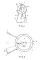
lens unit 11 are arranged will be described below with reference toFIGS. 4 to 7 .FIG. 4 shows the state of the cleaning liquid gushed from the wash nozzle flowing with respect to the pedestal.FIG. 5 is a view showing the positional relationship between the wash nozzles, andlens unit 11.FIG. 6 is a view showing a relationship between a distance X from a straight line passing through the central axis of the lens, and angle β between the lens central axis and water-gushing direction.FIG. 7 shows the state of the cleaning liquid gushed from the wash nozzles flowing with respect to the pedestal examined previously. - First, cleaning of the observation port using a cleaning liquid or a gaseous body will be described below.
- It is ideal that in the side-
viewing observation port 15 of thelens unit 11, the observation visual field range covers the entire circumference. However, as described previously, a pedestal is required to arrange a wash nozzle for each of the direct-viewing observation port 14, and side-viewing observation port 15. Thus, as shown inFIG. 7 , an idea of arranging a pedestal beside thelens unit 11 in the shape of a keyhole is conceivable. - In this arrangement, when the
rectangular pedestal 32 is made to abut on the side-viewing observation port 15, an idea of forming the keyhole shape in a constricted style by obliquely removing the corner of the part at which thepedestal 32 abuts on the side-viewing observation port 15 is conceivable in order to secure the observation visual field of the side-viewing observation port 15. In the case of a shape having such "constriction", washnozzles 31 are to be arranged on the lateral faces parallel to each other. Each of the wash nozzles 31 on the parallel lateral faces is to gush the cleaningliquid 21 not in the direction to the center (position identical to the center of the direct-viewing observation port 14 inFIG. 4 ) of the side-viewing observation port 14, but in the tangential direction of the circumferential face of the observation port. - Accordingly, as shown in
FIG. 7 , although part of the flow of the cleaningliquid 33 gushed from each of thewash nozzles 31 flows into the inside of the constricted part, the branched flow cannot thereafter join the flow of the cleaningliquid 33 which is the mainstream, and a situation in which the part of the flow is retained at the constricted part occurs. That is, it is conceivable that a foreign substance adhering to the constricted part will become hardly removable. In general, it is known that dirt is liable to collect at a constricted part, and it is difficult to remove the collected dirt. - Although it is sufficient if a wash nozzle is arranged at the constricted part, it is difficult to arrange a liquid-sending route or a gas-sending route at the constricted part. Further, although it is also possible to make the flow of the cleaning liquid go around via the constricted part by providing an auxiliary member such as a rectification board or the like upstream from the constricted part, when such an auxiliary member is provided at the tip part of the insertion section to be inserted into the body cavity, a situation in which a foreign subject gets jammed in the constricted part to thereby hinder the flow of the cleaning liquid is also conceivable. Thus, arranging such an auxiliary member is not desirable.
- In this embodiment, as shown in
FIG. 4 , the pedestal is formed into such a shape that the cleaning liquid gushed from the wash nozzle is immediately passed through the constricted part, and is then directed toward the circumferential face of the side-viewing observation port 15 by forming the lateral face on which the wash nozzle is to be arranged in an oblique direction, i.e., in a direction to the center of the side-viewing observation port 15. Here, the gushing angle, and the gushing position of the wash nozzle that make the gushed cleaning liquid flow along the circumferential face of the side-viewing observation port 15 become important. - Thus, as an examination example shown in
FIG. 5 , it is assumed that the diameter 2R of the cylindrical lens of the side-viewing observation port 15 is ϕ6.2 mm, and the amount of the cleaning liquid to be gushed is 37.5 mL. Further,FIG. 5 is shown by assuming that the lens diameter 2R of the side-viewing observation port 15 is identical to the diameter of thelens frame 12. As the angle β becomes larger, the size of thepedestal 13 becomes larger, and hence the visual field from the side-viewing observation port 15 is largely interrupted. For this reason, the angle β is made smaller than or equal to 45°. When the angle β exceeds 45°, the cleaningliquid 21 begins not to flow uniformly along the circumferential face of the lens. Further, when the angle α is greater than or equal to 180°, the cleaningliquid 21 can sufficiently go around via the top n. That is, the cleaning liquid can travel along the entire circumferential face of the lens. The result of the experiment carried out in this examination example is shown inFIG. 6 . Here, the X-axis indicates the angle β shown inFIG. 5 , and the Y-axis indicates the distance X shown inFIG. 5 . By this examination, the following result has been obtained. The angle β is greater than or equal to 5°, and smaller than or equal to 45°, and desirably smaller than or equal to 30°. The distance X from an oblique line passing through the central point of the lens having an angle of β to the lateral face is 1mm to 3mm, and desirably 1.5mm to 3mm. That is, a result indicating that a distance corresponding to 1 to 1/2 of the radius R of the lens is desirable has been obtained. It goes without saying that in this examination example, in the detailed part, a somewhat different result is conceivable depending on the lens diameter, and the amount of the liquid to be sent, and hence it is desirable that each of the detailed matters be verified at the time of design. - Hereinafter, items which provide results and tendencies that are universal to all the cases even when different lens diameters and amounts of the cleaning liquid to be sent are employed will be described below.
- a. The lateral faces are arranged oblique in such a manner that the direction of the cleaning liquid gushed from the aperture face (ejection hole) of each of two wash nozzles forms an acute angle greater than or equal to 5°, and smaller than or equal to 45° with a straight line passing through the center (center m of the side-viewing observation port 15) around which the flow of water is made to go along the circumferential face of the
observation port 15. Accordingly, the angle between the gushing directions of the cleaning liquid gushed from the two wash nozzles intersecting each other is about 10 to 90°. - b. When the lateral face (nozzle arrangement face) of the pedestal has an inclination of, for example, 45° or less, the first straight line along the lateral face, and the second straight line passing through the center m of the lens, and having an inclination identical to the inclination of the lateral face are parallel to each other, and the distance between the first and second straight lines is X, and the radius of the lens is R, the following relationship is obtained. 1/2R≤X<R
- According to this embodiment described above, it is possible to secure a space in which a liquid-sending route, gas-sending route, and various parts are to be arranged, and carry out cleaning in such a manner that a foreign substance adhering to the faces of the observation ports including the joint part between the cylindrical lens serving as the side-viewing observation port, and pedestal is efficiently and completely removed.
- Next, a second embodiment will be described below.
-
FIG. 9A is a view showing the external configuration of an insertion section tip of an endoscopic device according to the second embodiment, andFIG. 9B is a view showing the configuration of the insertion section tip viewed from the front. It should be noted that in the configuration parts of this embodiment, configuration parts identical to the configuration parts of the first embodiment described previously are denoted by identical reference symbols and their detailed description are omitted. - A
lens unit 51 of this embodiment has a shape of a circular truncated cone, whereas thelens unit 11 in the first embodiment is cylindrical. - As shown in
FIG. 9A , thelens unit 51 is constituted by laying alens frame 52a,truncated cone lens 53, andlens frame 52b one on top of the other, and is formed into a shape of a circular truncated cone smoothly tapered off. On the tip face which is the top face of the circular truncated cone, a direct-viewing observation port 14 is arranged. - A
pedestal section 54 is joined to thelens unit 51 in such a manner that the joint part between thepedestal section 54, andlens unit 51 forms oblique lines directed toward the direct-viewing observation port 14 side. Further, as in the first embodiment, in both of or one of thelens frames - The lens frames 52a, and 52b guide the illumination light branched from the light guide, and applies the illumination light in the laterally circumferential direction from the lens frame surfaces.
- According to this embodiment, a function, and advantage identical to the first embodiment are produced. The joint part between the side-
viewing observation port 53, andpedestal section 54 is in an oblique direction with respect to the direction in which the cleaning liquid or the gaseous body is gushed, and hence when the insertion section is moved, a foreign substance adhering to the insertion section moves in flux, and becomes hardly sticky. Furthermore, the gushed cleaning liquid or gaseous body continuously flows along the joint part in the oblique direction toward the tip side or the rear end side, and hence cleaning can be carried out by removing the dirt or the like more thoroughly. - 1...endoscope main body, 2...trolley, 3...operation section, 4...insertion section (flexible tube), 5...bending section, 6...universal cable, 7...endoscopic apparatus, 8...bottle, 9...connector, 10...suction unit, 11...lens unit, 12, 12a, 12b, 52, 52a, 52b...lens frame, 13, 54...pedestal, 14...direct-viewing observation port, 15, 53...side-viewing observation port, 16, 17, 21...wash nozzle, 18...illumination port, 19...aperture section, 20a...nozzle aperture face, 20b, 20c...aperture, 34...gas-sending pump unit, 41...circular concave lens (cylindrical lens), 42, 42a, 42b...first lens group, 43, 43a, 43b, 43c, 43d, 43e...second lens group.
Claims (7)
- An endoscopic device including a cleaning mechanism characterized by comprising:a cylindrical lens arranged at a tip of an insertion section of an endoscope as an optical member for observation with a face thereof laterally circumferential with respect to an axial direction which is an insertion direction exposed to the outside;a pedestal section two lateral faces of which obliquely and straightly extending toward the central side of the cylindrical lens are joined to the laterally circumferential face, and inside which a liquid-sending route configured to send a cleaning liquid, and a gas-sending route configured to send a gaseous body are internally provided; andtwo wash nozzles each of which is provided on each of the two lateral faces, and is configured to selectively gush a fluid current obtained by mixing the cleaning liquid, and the gaseous body, only the liquid or only the gaseous body,an angle which gushing directions of the cleaning liquid straightly gushed from the two wash nozzles toward the laterally circumferential faces form with each other is an acute angle, the gushing directions intersecting each other, the cleaning liquid flows along the laterally circumferential face via the joint part between the pedestal section, and the laterally circumferential face.
- The endoscopic device according to claim 1, characterized in that the wash nozzles are arranged on both the lateral faces in such a manner that the gushing direction of the cleaning liquid straightly gushed from each of the wash nozzles forms an angle greater than or equal to 5°, and smaller than or equal to 30° with a straight line passing through a center of the cylindrical lens in a radial direction.
- The endoscopic device according to claim 1, characterized in that a distance X between a first straight line along one of the lateral faces of the pedestal section, and a second straight line passing through the center of the cylindrical lens with an inclination identical to the inclination of the first straight line, and parallel to the first straight line, and a lens radius R of the cylindrical lens satisfies the following relationship.

- The endoscopic device according to claim 1, characterized in that a lens group including the cylindrical lens provided at the tip of the insertion section constitutes a side-viewing observation port configured to make a light figure of an observation object incident on the laterally circumferential face, and
furthermore, a first lens arranged on the front side of the cylindrical lens at the tip of the insertion section in a superposing manner constitutes a direct-viewing observation port configured to make a light figure of an observation object in the axial direction incident thereon. - The endoscopic device according to claim 4, characterized in that the side-viewing observation port, and the direct-viewing observation port assume an external appearance of a cylindrical shape.
- The endoscopic device according to claim 4, characterized in that the side-viewing observation port, and the direct-viewing observation port assume an external appearance of a circular truncated cone.
- The endoscopic device according to claim 4, characterized in that at least part of a lens frame configured to support the lens group of the side-viewing observation port, and the first lens of the direct-viewing observation port is formed of a light guiding member configured to guide illumination light, and irradiates an observation visual field of the side-viewing observation port with illumination light.
Applications Claiming Priority (2)
| Application Number | Priority Date | Filing Date | Title |
|---|---|---|---|
| JP2012216301 | 2012-09-28 | ||
| PCT/JP2013/067543 WO2014050236A1 (en) | 2012-09-28 | 2013-06-26 | Endoscope device having cleaning mechanism |
Publications (2)
| Publication Number | Publication Date |
|---|---|
| EP2901913A1 true EP2901913A1 (en) | 2015-08-05 |
| EP2901913A4 EP2901913A4 (en) | 2016-08-31 |
Family
ID=50387653
Family Applications (1)
| Application Number | Title | Priority Date | Filing Date |
|---|---|---|---|
| EP13842411.4A Withdrawn EP2901913A4 (en) | 2012-09-28 | 2013-06-26 | Endoscope device having cleaning mechanism |
Country Status (4)
| Country | Link |
|---|---|
| US (1) | US20150073218A1 (en) |
| EP (1) | EP2901913A4 (en) |
| JP (1) | JP5583873B1 (en) |
| WO (1) | WO2014050236A1 (en) |
Cited By (2)
| Publication number | Priority date | Publication date | Assignee | Title |
|---|---|---|---|---|
| CN113798245A (en) * | 2021-09-15 | 2021-12-17 | 中国科学院长春光学精密机械与物理研究所 | Endoscope flushing nozzle and endoscope flushing device |
| US11317784B2 (en) | 2017-08-23 | 2022-05-03 | Olympus Corporation | Endoscope |
Families Citing this family (30)
| Publication number | Priority date | Publication date | Assignee | Title |
|---|---|---|---|---|
| DE10154163A1 (en) | 2001-11-03 | 2003-05-22 | Advanced Med Tech | Device for straightening and stabilizing the spine |
| US8979931B2 (en) | 2006-12-08 | 2015-03-17 | DePuy Synthes Products, LLC | Nucleus replacement device and method |
| US20090088789A1 (en) | 2007-09-28 | 2009-04-02 | O'neil Michael J | Balloon With Shape Control For Spinal Procedures |
| US9387009B2 (en) | 2007-10-05 | 2016-07-12 | DePuy Synthes Products, Inc. | Dilation system and method of using the same |
| US9622779B2 (en) | 2011-10-27 | 2017-04-18 | DePuy Synthes Products, Inc. | Method and devices for a sub-splenius / supra-levator scapulae surgical access technique |
| WO2013067179A2 (en) | 2011-11-01 | 2013-05-10 | Synthes Usa, Llc | Dilation system |
| US9265490B2 (en) | 2012-04-16 | 2016-02-23 | DePuy Synthes Products, Inc. | Detachable dilator blade |
| US9480855B2 (en) | 2012-09-26 | 2016-11-01 | DePuy Synthes Products, Inc. | NIR/red light for lateral neuroprotection |
| US9980737B2 (en) | 2014-08-04 | 2018-05-29 | Medos International Sarl | Flexible transport auger |
| US10111712B2 (en) | 2014-09-09 | 2018-10-30 | Medos International Sarl | Proximal-end securement of a minimally invasive working channel |
| US9924979B2 (en) | 2014-09-09 | 2018-03-27 | Medos International Sarl | Proximal-end securement of a minimally invasive working channel |
| US10264959B2 (en) | 2014-09-09 | 2019-04-23 | Medos International Sarl | Proximal-end securement of a minimally invasive working channel |
| US10786264B2 (en) | 2015-03-31 | 2020-09-29 | Medos International Sarl | Percutaneous disc clearing device |
| US12150636B2 (en) | 2015-09-04 | 2024-11-26 | Medos International Sárl | Surgical instrument connectors and related methods |
| US11672562B2 (en) | 2015-09-04 | 2023-06-13 | Medos International Sarl | Multi-shield spinal access system |
| CN113143355A (en) | 2015-09-04 | 2021-07-23 | 美多斯国际有限公司 | Multi-shield spinal access system |
| US11439380B2 (en) | 2015-09-04 | 2022-09-13 | Medos International Sarl | Surgical instrument connectors and related methods |
| US11744447B2 (en) | 2015-09-04 | 2023-09-05 | Medos International | Surgical visualization systems and related methods |
| US10987129B2 (en) | 2015-09-04 | 2021-04-27 | Medos International Sarl | Multi-shield spinal access system |
| WO2017126196A1 (en) * | 2016-01-18 | 2017-07-27 | オリンパス株式会社 | Endoscope |
| US10299838B2 (en) | 2016-02-05 | 2019-05-28 | Medos International Sarl | Method and instruments for interbody fusion and posterior fixation through a single incision |
| WO2017217269A1 (en) * | 2016-06-14 | 2017-12-21 | オリンパス株式会社 | Endoscope |
| JP6564752B2 (en) * | 2016-09-26 | 2019-08-21 | 富士フイルム株式会社 | Endoscope |
| JP7092633B2 (en) | 2018-10-11 | 2022-06-28 | 富士フイルム株式会社 | Endoscope system |
| CN111437496A (en) * | 2019-01-16 | 2020-07-24 | 沈伟 | A liquid medicine spraying device in an endoscope forceps channel |
| US11013530B2 (en) | 2019-03-08 | 2021-05-25 | Medos International Sarl | Surface features for device retention |
| US11241252B2 (en) | 2019-03-22 | 2022-02-08 | Medos International Sarl | Skin foundation access portal |
| US11129727B2 (en) | 2019-03-29 | 2021-09-28 | Medos International Sari | Inflatable non-distracting intervertebral implants and related methods |
| US11813026B2 (en) | 2019-04-05 | 2023-11-14 | Medos International Sarl | Systems, devices, and methods for providing surgical trajectory guidance |
| US11771517B2 (en) | 2021-03-12 | 2023-10-03 | Medos International Sarl | Camera position indication systems and methods |
Family Cites Families (12)
| Publication number | Priority date | Publication date | Assignee | Title |
|---|---|---|---|---|
| DE4035146A1 (en) * | 1990-11-06 | 1992-05-07 | Riek Siegfried | INSTRUMENT FOR PENETRATING BODY TISSUE |
| US5207213A (en) * | 1991-02-01 | 1993-05-04 | Circon Corporation | Laparoscope having means for removing image impeding material from a distal lens |
| US5386817A (en) * | 1991-06-10 | 1995-02-07 | Endomedical Technologies, Inc. | Endoscope sheath and valve system |
| JPH05103752A (en) | 1991-10-16 | 1993-04-27 | Olympus Optical Co Ltd | Endoscope |
| JP3526531B2 (en) * | 1998-06-19 | 2004-05-17 | 富士写真光機株式会社 | Advanced structure of stereoscopic endoscope |
| JP3785908B2 (en) * | 2000-08-17 | 2006-06-14 | フジノン株式会社 | Endoscope observation window cleaning device |
| JP5074114B2 (en) | 2007-07-09 | 2012-11-14 | オリンパス株式会社 | Optical element, optical system including the same, and endoscope using the same |
| JP5289987B2 (en) | 2009-01-21 | 2013-09-11 | オリンパス株式会社 | Optical element and optical unit using the same |
| JP4782900B2 (en) * | 2009-11-06 | 2011-09-28 | オリンパスメディカルシステムズ株式会社 | Endoscope |
| JP4850315B2 (en) * | 2009-11-06 | 2012-01-11 | オリンパスメディカルシステムズ株式会社 | Endoscope apparatus and endoscope |
| JP5554153B2 (en) * | 2010-06-11 | 2014-07-23 | 富士フイルム株式会社 | Endoscope |
| CN102665529B (en) * | 2010-07-08 | 2015-04-15 | 奥林巴斯医疗株式会社 | Endoscope |
-
2013
- 2013-06-26 JP JP2014508638A patent/JP5583873B1/en active Active
- 2013-06-26 EP EP13842411.4A patent/EP2901913A4/en not_active Withdrawn
- 2013-06-26 WO PCT/JP2013/067543 patent/WO2014050236A1/en not_active Ceased
-
2014
- 2014-11-12 US US14/539,379 patent/US20150073218A1/en not_active Abandoned
Cited By (3)
| Publication number | Priority date | Publication date | Assignee | Title |
|---|---|---|---|---|
| US11317784B2 (en) | 2017-08-23 | 2022-05-03 | Olympus Corporation | Endoscope |
| CN113798245A (en) * | 2021-09-15 | 2021-12-17 | 中国科学院长春光学精密机械与物理研究所 | Endoscope flushing nozzle and endoscope flushing device |
| CN113798245B (en) * | 2021-09-15 | 2022-07-19 | 中国科学院长春光学精密机械与物理研究所 | Chamber mirror washing nozzle and chamber mirror washing unit |
Also Published As
| Publication number | Publication date |
|---|---|
| EP2901913A4 (en) | 2016-08-31 |
| US20150073218A1 (en) | 2015-03-12 |
| JP5583873B1 (en) | 2014-09-03 |
| JPWO2014050236A1 (en) | 2016-08-22 |
| WO2014050236A1 (en) | 2014-04-03 |
Similar Documents
| Publication | Publication Date | Title |
|---|---|---|
| EP2901913A1 (en) | Endoscope device having cleaning mechanism | |
| CN103491854B (en) | Multicomponent cover for many cameras endoscope | |
| JP6054874B2 (en) | Flexible electronic circuit board for multi-camera endoscope | |
| JP2014524819A (en) | Multi-camera endoscope | |
| JP2015533300A (en) | Multi-camera endoscope | |
| US20150313451A1 (en) | Elevator for Directing Medical Tool | |
| JP6728480B2 (en) | Endoscope | |
| JP2013123647A (en) | Endoscope with removable distal end | |
| JP5583880B1 (en) | Stereoscopic endoscope | |
| JPWO2018179792A1 (en) | Endoscope | |
| CN101703415B (en) | Hard ultrasonic gallbladder endoscope system | |
| US11042020B2 (en) | Endoscope having observation window with circumferential side surface and cleaning nozzles directed to circumferential side surface | |
| CN100518620C (en) | Endoscope-use insertion unit | |
| US20160192822A1 (en) | Tubed Manifold of a Multiple Viewing Elements Endoscope | |
| US20150359421A1 (en) | Gas supply and liquid supply apparatus | |
| EP3424435A1 (en) | Ultrasonic endoscope | |
| US8936547B2 (en) | Endoscope gas feed system, endoscope, and endoscope system | |
| US10799103B2 (en) | Endoscope having image acquisition windows and corresponding cleaning nozzles on front and circumferential surfaces | |
| JP6439081B2 (en) | Endoscope | |
| JP6165396B1 (en) | Endoscope | |
| CN101098656A (en) | Insertion part for endoscope | |
| JPH08545A (en) | Cover type endoscope | |
| JP4844963B2 (en) | Endoscope | |
| JP2023132682A (en) | Rigid endoscope cover and endoscope unit | |
| JP6523062B2 (en) | Endoscope device |
Legal Events
| Date | Code | Title | Description |
|---|---|---|---|
| PUAI | Public reference made under article 153(3) epc to a published international application that has entered the european phase |
Free format text: ORIGINAL CODE: 0009012 |
|
| 17P | Request for examination filed |
Effective date: 20150420 |
|
| AK | Designated contracting states |
Kind code of ref document: A1 Designated state(s): AL AT BE BG CH CY CZ DE DK EE ES FI FR GB GR HR HU IE IS IT LI LT LU LV MC MK MT NL NO PL PT RO RS SE SI SK SM TR |
|
| AX | Request for extension of the european patent |
Extension state: BA ME |
|
| RAP1 | Party data changed (applicant data changed or rights of an application transferred) |
Owner name: OLYMPUS CORPORATION |
|
| DAX | Request for extension of the european patent (deleted) | ||
| RA4 | Supplementary search report drawn up and despatched (corrected) |
Effective date: 20160728 |
|
| RIC1 | Information provided on ipc code assigned before grant |
Ipc: G02B 23/24 20060101ALI20160722BHEP Ipc: A61B 1/015 20060101ALI20160722BHEP Ipc: A61B 1/00 20060101AFI20160722BHEP |
|
| RAP1 | Party data changed (applicant data changed or rights of an application transferred) |
Owner name: OLYMPUS CORPORATION |
|
| STAA | Information on the status of an ep patent application or granted ep patent |
Free format text: STATUS: REQUEST FOR EXAMINATION WAS MADE |
|
| STAA | Information on the status of an ep patent application or granted ep patent |
Free format text: STATUS: THE APPLICATION IS DEEMED TO BE WITHDRAWN |
|
| 18D | Application deemed to be withdrawn |
Effective date: 20190103 |