EP2901861A1 - Skinning apparatus - Google Patents
Skinning apparatus Download PDFInfo
- Publication number
- EP2901861A1 EP2901861A1 EP15152997.1A EP15152997A EP2901861A1 EP 2901861 A1 EP2901861 A1 EP 2901861A1 EP 15152997 A EP15152997 A EP 15152997A EP 2901861 A1 EP2901861 A1 EP 2901861A1
- Authority
- EP
- European Patent Office
- Prior art keywords
- skin
- clamping
- clamping device
- jaw
- freed
- Prior art date
- Legal status (The legal status is an assumption and is not a legal conclusion. Google has not performed a legal analysis and makes no representation as to the accuracy of the status listed.)
- Granted
Links
Images


Classifications
-
- A—HUMAN NECESSITIES
- A22—BUTCHERING; MEAT TREATMENT; PROCESSING POULTRY OR FISH
- A22B—SLAUGHTERING
- A22B5/00—Accessories for use during or after slaughtering
- A22B5/16—Skinning instruments or knives
- A22B5/161—Methods or means for pulling the hide from carcasses
Definitions
- the present invention relates to a skinning apparatus for skinning fur animals, especially minks, which have been cut open along and between the legs, and from which skin has been loosened and freed from the rear portion of the body and the rear legs and the tail, said apparatus comprising:
- Skinning apparatuses of the above stated type are known from DK 176 580 B1 and DK 165 768 B having a moving means formed by a swivel arm.
- the body portion initially freed from the skin is clamped in the upper clamping device with the back of the animal facing forwards, while the swivel arm is positioned in a downwardly pivoted position thereof.
- the operator draws additional skin from the body in order to provide a larger portion of freed skin.
- the swivel arm is then pivoted upwards into its upper position.
- the mentioned apparatuses are arranged in such a way that the skin-clamping device passes by the body clamped in the body-clamping device when the skin-clamping device is moved into its skin-clamping position which allows for clamping the back of the freed skin.
- the swivel arm is pivoted downwardly and into its end position, and the skin is thereby fully removed from the body. Pulling off additional skin from the body is a demanding, hard and time-consuming job for the operator of the apparatus. Additionally, it is time consuming to move the swivel arm from the lower end position to the upper clamping position of the skin-clamping device after clamping the body portion in the body-clamping device.
- the object of the present invention is to eliminate or reduce the drawbacks of the above known apparatuses.
- the skin-clamping device In the skin-clamping position, the skin-clamping device is positioned in close proximity to the body-clamping device allowing the animal to be arranged in said clamping device with the back thereof facing outwardly, i.e. the legs to be arranged in the body clamping device, the rear portion of the body freed from skin to be arranged in the cavity of the upper jaw through the opening thereof, the freed skin portion to be arranged between the upper and lower jaw, and the body portion not freed from skin to be arranged in the cavity of the lower jaw through the opening thereof.
- the legs are clamped in the body-clamping device.
- the lower displaceable jaw of the skin-clamping jaw is then displaced towards the fixed jaw, and the freed skin portion is thereby clamped in the skin-clamping device.
- At least the lateral areas of the initially freed skin portion are clamped in the skin-clamping device.
- the skin-clamping device is moved downwardly by means of the skin moving means in order to carry out the skinning.
- the legs of the animal can be placed and clamped in the body-clamping device, and the freed skin portion can be placed and clamped in the skin-clamping device in the start position of the clamping devices, there is no need for the operator to carry out the demanding, hard and time-consuming work of drawing additional skin from the body before clamping the skin in the skin-clamping device.
- the apparatus according to the invention allows for skinning animals without the need of carrying out a manual extension of the initially freed skin portion. Further, the apparatus according to the invention allows for skinning animals having a considerable shorter initially free skin portion than the above-mentioned known apparatuses.
- the skin-moving means comprises a swivel arm, the skin-clamping device being arranged at a first end of the swivel arm, a second end of the swivel arm being pivotally connected to the frame, said skin-clamping device being by means of the arm pivotal between the upper start and skin-clamping position and lower position, and the upper fixed jaw being connected to the swivel arm and the lower displaceable jaw being displaceably connected to the swivel arm.
- the skin moving means comprises a conveyer, chain drive and/or a track to which the skin-clamping device is connected.
- the cavity of the lower displaceable jaw is shaped and dimensioned so that the inner surface thereof engages at least opposite lateral portions of the body not freed from skin when the body is received in the cavity. As a result thereof, the not yet skinned portions of the animal is positioned correctly in the skin-clamping device.
- the cavity of the fixed jaw is shaped and dimensioned so that the inner surface thereof engages at least lateral portions of the body freed from skin when the body is received in the cavity, thereby ensuring that the body portion freed from skin is positioned correctly in the skin-clamping device.
- the arms of the lower displaceable jaw of the skin-clamping device are elongated arms providing an elongated inner surface, as seen in the displacement direction thereof, said inner surface providing a support face for a body received in the cavity defined by the elongated arms.
- the lower displaceable jaw has a length providing a support face for the animal, it is more convenient for the operator to arrange the animal in the clamping devices.
- the support face of the elongated displaceable jaw is in the start and clamping position of the skin-clamping device preferably sloping slightly forwardly and downwardly as seen from the upper fixed jaw.
- the slope angle can be 5-35°, preferably 5-25°.
- the elongated arms and thereby the support face thereof can have a length of at least 5 cm, 10 cm, 15 cm or 20 cm.
- the lower displaceable jaw can have a cross section essentially corresponding to that of a trough, such as an essentially U-shaped or V-shaped cross-section.
- the upper fixed jaw can have a cross section essentially corresponding to that of a trough, such as a U-shaped or V-shaped cross section.
- the apparatus optionally the skin-clamping device thereof, is provided with a tail clamp for clamping the freed skin of the tail of a body received in the skin-clamping device, the tail clamp being arranged movably between a tail-clamping position in which the tail is clamped between jaws of the tail clamp and a rest position or inactive position in which the tail clamp is positioned laterally outside a vertical area defined by the openings of the skin-clamping device.
- the tail clamp in its rest or inactive position is laterally outside a vertical area defined by the openings of the jaws of the skin-clamping device, it does not interfere when the legs are clamped in the body-clamping device and the rest of the animal is arranged in the skin-clamping device, as the tail clamp is not moved into the clamping position and the tail is not clamped until after the animal has been arranged in the clamping devices.
- the tail clamp is arranged at a first end of a tail clamp arm, a second end of the tail clamp arm being arranged pivotally relative to the skin-clamping device, the tail clamp being, by means of the tail clamp arm, pivotal between the inactive or rest position and the clamping position.
- the second end of the tail clamp arm can be connected pivotally to the swivel arm at the first end thereof.
- the tail-clamping position is essentially defined by the lower clamping face of the upper fixed jaw of the skin-clamping device and the tail clamp arranged to clamp the tail in said plane and preferably in a position essentially directly in front of the opening of the upper jaw of the skin-clamping device.
- the apparatus comprises a body movement means cooperating with or being a part of the body-clamping device for providing an upwardly and rearward movement of the body clamped therein between the clamping and start position thereof to a discharge position where the completely freed skin is discharged.
- the body movement means may comprise an upwardly and rearward extending conveyer, chain drive and/ or track to which the body-clamping device is connected.
- the body movement means can be one or more pairs of oppositely arranged rollers or oppositely arranged conveyers such as belt conveyers provided with engagement means, such as spikes, engaging the body as disclosed in DK 176580 B1 .
- the body movement means is arranged to move the body-clamping device with at least two different speeds from the clamping position to the discharge position, comprising a first speed and a second speed, the first speed being higher than the second speed.
- the first high speed is used during the skinning af the animal from the rear portion thereof and up to about the shoulder of the front legs of the animal, whereupon the second low speed is used.
- the movement means is provided with stop means slowing down, and/or interrupting or stopping the movement of the body-clamping device at one or more adjustable intermediate positions between the clamping positions and the discharge position.
- the clamping may continue the movement from said stop position to a discharge position where the body freed for the skin is discharged
- the skin moving means is arranged to move the skin-clamping device with at least two different speeds comprising a first predefined speed and a second predefined speed, the first predefined speed being higher than the second predefined speed.
- the first predefined speed is used from the beginning of the skinning and up to the skinning of the shoulder at the front legs of the body, whereafter the second lower speed is used.
- the speed is preferable reduced to a low speed optionally a speed about zero in order to be able to free the skin from the head.
- the skin moving means is provided with stop means for slowing down and/or interrupting or stopping the movement of the skin-clamping device at one or more adjustable positions between the upper start and skin clamping position and the lower end position.
- the apparatus can have a transverse skin-supporting member, such as a roller, provided between the body-clamping device and the skin-clamping device, said transverse skin-supporting member being arranged to support the body being freed from skin during the skinning.
- the apparatus may comprise an additional clamping device for clamping the body freed from the skin in the area of the shoulder area of the front legs during skinning of the head portion of the animal.
- the additional clamping device can comprise a shoulder clamp arranged at an forward end of a bar connected moveably to the frame between a retracted inactive rest position and a forwardly projecting clamping position clamping the shoulder area of the front legs.
- the additional clamping device may comprise two cooperating jaws cooperating to clamp said shoulder area.
- the embodiment of the skinning apparatus shown in the drawings is arranged for skinning minks which have been cut open along the legs and from which the skin has been loosened and freed from the rear portion of the body, the rear legs and the tail.
- the apparatus comprises a frame 1 having a front 2, rear 3 a bottom 4 and a top 5, and additionally a body-clamping device 6 for clamping the legs 7 and/or rear portion of the body of the mink and a skin-clamping device 8 for clamping the skin portion 9 freed from the body.
- the body-clamping device 6 is accessible from the front in a clamping and start position thereof shown in Figs. 1 , 3 , 5 and 6 and arranged in an upper portion of the apparatus.
- the body-clamping device comprises a lower body-clamping jaw 10 and an upper moveable body-clamping jaw 11 movable between an open position shown in Figs. 1 , 3 and 4 and a closed position shown in Fig. 6 , and where it appears that the legs 7 have been clamped.
- the body-clamping device is arranged movably between the start position shown in Figs. 1 , 3 , 4 and 6 and an end position shown in Figs. 2 and 4 in which the body freed from the skin is discharged.
- the body-clamping device is moveable along a linear track 12 comprising a linear guide and a chain drive extending upwardly and rearward. A lower chain wheel 13 of the chain drive is visible in Figs. 3 , 4 and 7 .
- An upper chain wheel is driven by a motor 14.
- the body clamping device 6 and the linear track 12 is covered by a downwardly open screen 16 allowing the skinned body be to discharged to a conveyer belt 17 arranged beneath the linear track 12 when the skinned body is released from the body-clamping device 6 in the end position thereof shown in Figs. 2 and 4 or another position between the start position and the end position.
- the chain drive including the motor is arranged for stopping the body-clamping device 6 at any preselected position between the start and the end position.
- the chain drive is arranged to move the body-clamping device 6 with at least two different speeds from the lower body clamping position and the upper discharge position, comprising a first speed and a second speed, the first speed being higher than the second speed and being preferably used during the first part of the skinning, the second speed being preferably used during the last more difficult part of the skinning.
- the skin-clamping device 8 for clamping the skin freed from the body is arranged at a first outer end 18 of a swivel arm 19, a second end 20 thereof being pivotally connected to the frame 1.
- the skin-clamping device 8 is pivotal between a clamping and start position shown in Figs. 1 , 3 , 5 and 6 in which it is accessible at the front 2 and positioned in close proximity to the body-clamping device 6 and an end position shown in Figs. 2 and 4 and in which the skin has been completely separated from the body.
- a drive for driving the swivel arm 19 is provided with stop means for stopping the pivotal movement of the arm at adjustable positions between the start and clamping position and the end position.
- the drive of the swivel arm is arranged for pivoting the arm with at least two different speeds from the start position to the end position or an intermediate position comprising a first speed and a second speed, the first speed being higher than the second speed and being preferably used during the first part of the skinning, the second lower speed being preferably used during last more difficult skinning of the shoulder and head area of the animal.
- the skin-clamping device 8 comprises an upper fixed jaw 21 connected to the swivel arm and a lower displaceable jaw 22 being displaceably connected to the swivel arm.
- the displaceable jaw 22 is linear displaceable away from and toward towards the fixed jaw 21 between an open position and a closed clamping position. In the open position, the spacing between the upper and lower jaw allows the previously loosened and freed skin portion to be inserted between the jaws and subsequently clamped between the jaws.
- the upper fixed jaw 21 is a forwardly open jaw comprising a pair of arms 23a, 23b being shaped to define a forwardly open cavity 24 with a forwardly facing opening 25 and having a lower clamping face 26.
- the inner cavity is defined by an inner surface 27 and shaped and dimensioned to receive the body portion being freed from skin through the opening 25.
- the cavity 24 of the upper fixed jaw 21 is preferably dimensioned so that the inner surface thereof engages at least lateral portions of the body when the body is received in the cavity.
- the upper fixed jaw is essentially V-shaped as most clearly shown in Figs. 3 , 4 and 7 .
- the lower displaceable jaw 22 is a forwardly open jaw comprising a pair of arms 28a, 28b being shaped to define a forwardly open cavity 29 with a forwardly facing opening 30 and having an upper clamping face 31.
- the cavity 29 of the lower jaw 22 is defined by an inner surface 32 and shaped and dimensioned to receive the body portion not being freed from skin through the opening.
- the cavity 29 of the lower jaw 22 is dimensioned so that the inner surface 32 thereof engages at least lateral portions of the not skinned body when the body is received in the cavity 29.
- the lower jaw 23 has an essentially V-shaped cross section and the inner surface 32 thereof formed by the arms thereof is elongated as seen in the displacement direction of the lower jaw. The inner surface thereby forms a support face for a body received in the cavity 29.
- the skin-clamping device 8 and thereby also the lower jaw 22 is sloping upwardly and rearward towards the body-clamping device 6. Additionally, it can be seen from Fig. 1 that a horizontal roller 33 for supporting the body during the skinning is connected with the frame between the start position of the body-clamping device 6 and the start position of the skin-clamping device 8.
- a tail clamp 34 for clamping the tail skin freed from the body is pivotally connected to the first outer end 18 of the swivel arm 19 by means of a tail clamp arm 35.
- the tail clamp 34 is pivotal between a tail-clamping position in which the tail skin is clamped between clamp jaws 36, 37 of the tail clamp, as shown in Fig. 6 , and a rest position or inactive position in which the tail clamp is positioned laterally outside a vertical area defined by the openings of the jaws of the skin-clamping device, as shown in Figs. 3 and 5 .
- the tail clamps 36, 37 are an upper fixed jaw 36 having a lower clamp face 38 and a lower moveable jaw 37 having an upper clamp face 39 and being moveable between an open and a closed position.
- the lower clamp face 38 of the upper clamp jaw 36 is positioned in a plane formed by the lower clamping face 26 of the upper fixes jaw 21 of the skin-clamping device 8.
- the pivotal connection of the tail clamp arm to the swivel is preferably arranged to move the lower clamp face 38 in the plane defined by the lower clamping face 26 of the upper fixed jaw 21 of the skin-clamping device.
- tail clamp 34 is positioned essentially directly in front of opening of the upper jaw 21 of the skin-clamping device.
- the apparatus comprises an additional device 40 arranged at a level between the body-clamping device 6 and the skin clamping device 8 in the start positions thereof.
- the additional clamping device comprises two clamping jaws 41, 42 movable between an open position shown in Figs. 3 , 5 and 6 , in which they do not interfere with the positioning or skinning of a mink to be skinned and a closed position in which the jaws clamp the body of the mink being skinned at the shoulder area of the front legs during skinning of the head region of the mink.
- the clamping position is shown in Figs. 4 and 7 , however, the skinned body and the skin not being shown.
- the apparatus operates as follows:
- the mink is arranged in the said devices with the back facing forwardly.
- the legs 7 are clamped in the body-clamping device as illustrated in Figs. 5 and 6 .
- the body portion freed from skin is arranged in the cavity of the upper jaw of the skin-clamping device 8, the freed skin portion is arranged in the opening between the jaws 21, 22 of the skin-clamping device 8 and the portion of the mink not freed from skin is arranged in the cavity of the lower jaw 22 of the skin-clamping device 8 as shown in Fig. 3 .
- the tail clamp 34 is now pivoted into its tail-clamping position and the tail skin 43 is arranged between the jaws 36,37 thereof. Subsequently, the skin-clamping device 8 and the tail clamp 34 are closed as shown in Fig. 6 . In this position, the body clamp 6 is moved upwardly along the track 12 and the swivel arm, and thereby the skin-clamping device is pivoted downwards. As a result of the above mentioned movement, the distance between the body-clamping device and the skin-clamping device is gradually increased and the mink thereby gradually skinned. When the skin has been drawn off to the point adjacent the head, the additional clamping device is activated and the shoulder area of the body clamped whereupon the reminder portion of the mink is skinned.
- the first portion of the skinning advantageously takes place at a higher speed than the last part.
- the skinned body is dislodged onto the conveyer belt 17, the separated skin released from the skin-clamping device 8 and the tail clamp. Thereupon the different clamping devices are moved into the start positions thereof. The apparatus is then ready for skinning an additional mink.
Landscapes
- Life Sciences & Earth Sciences (AREA)
- Engineering & Computer Science (AREA)
- Food Science & Technology (AREA)
- Processing Of Meat And Fish (AREA)
- Apparatuses For Bulk Treatment Of Fruits And Vegetables And Apparatuses For Preparing Feeds (AREA)
Abstract
Description
- The present invention relates to a skinning apparatus for skinning fur animals, especially minks, which have been cut open along and between the legs, and from which skin has been loosened and freed from the rear portion of the body and the rear legs and the tail, said apparatus comprising:
- a frame having a front, a rear, a top and a bottom
- a body-clamping device for clamping said legs and/or rear portion of the body freed for the skin in a start and body-clamping position and being accessible at the front,
- a skin clamping device for clamping the skin freed from the body and being by means of a moving means arranged for a downwardly and rearwardly movement between an upper start and skin-clamping position and a lower position at a distance from the upper skin-clamping position and in which the skin has been completely separated from the body,
- the skin-clamping device being in the upper skin-clamping position positioned adjacent to the body-clamping device and being accessible at the front.
- Skinning apparatuses of the above stated type are known from
DK 176 580 B1 DK 165 768 B - The object of the present invention is to eliminate or reduce the drawbacks of the above known apparatuses.
- The above problems are solved by an apparatus according to the invention being characterised in that
- the skin-clamping device comprises an upper fixed jaw and a lower displaceable jaw being displaceable away from and towards the fixed jaw between an open position and a closed clamping position.
- the upper fixed jaw is a forwardly open jaw comprising a pair of optionally mutually connected arms shaped to define a forwardly open cavity with a forwardly facing opening and having a lower clamping face and an inner surface defining the forwardly open cavity shaped and dimensioned to receive the body portion freed from skin.
- the lower displaceable jaw is a forwardly open jaw comprising a pair of optionally mutually connected arms shaped to define a forwardly open cavity with a forwardly facing opening and having an upper clamping face and an inner surface defining the forwardly open cavity shaped and dimensioned to receive the body portion not being freed from skin.
- the upper clamping surface of the lower displaceable jaw is in the open position thereof spaced from the lower clamping surface to receive the freed skin portion between said clamping faces.
- In the skin-clamping position, the skin-clamping device is positioned in close proximity to the body-clamping device allowing the animal to be arranged in said clamping device with the back thereof facing outwardly, i.e. the legs to be arranged in the body clamping device, the rear portion of the body freed from skin to be arranged in the cavity of the upper jaw through the opening thereof, the freed skin portion to be arranged between the upper and lower jaw, and the body portion not freed from skin to be arranged in the cavity of the lower jaw through the opening thereof.
- Initially, the legs are clamped in the body-clamping device. The lower displaceable jaw of the skin-clamping jaw is then displaced towards the fixed jaw, and the freed skin portion is thereby clamped in the skin-clamping device.
- At least the lateral areas of the initially freed skin portion are clamped in the skin-clamping device.
- Finally, the skin-clamping device is moved downwardly by means of the skin moving means in order to carry out the skinning. As the legs of the animal can be placed and clamped in the body-clamping device, and the freed skin portion can be placed and clamped in the skin-clamping device in the start position of the clamping devices, there is no need for the operator to carry out the demanding, hard and time-consuming work of drawing additional skin from the body before clamping the skin in the skin-clamping device.
- In other words, the apparatus according to the invention allows for skinning animals without the need of carrying out a manual extension of the initially freed skin portion. Further, the apparatus according to the invention allows for skinning animals having a considerable shorter initially free skin portion than the above-mentioned known apparatuses.
- According to an embodiment, the skin-moving means comprises a swivel arm, the skin-clamping device being arranged at a first end of the swivel arm, a second end of the swivel arm being pivotally connected to the frame, said skin-clamping device being by means of the arm pivotal between the upper start and skin-clamping position and lower position, and the upper fixed jaw being connected to the swivel arm and the lower displaceable jaw being displaceably connected to the swivel arm.
- In an embodiment, the skin moving means comprises a conveyer, chain drive and/or a track to which the skin-clamping device is connected.
- According to an embodiment of the invention, the cavity of the lower displaceable jaw is shaped and dimensioned so that the inner surface thereof engages at least opposite lateral portions of the body not freed from skin when the body is received in the cavity. As a result thereof, the not yet skinned portions of the animal is positioned correctly in the skin-clamping device.
- According to an additional embodiment, the cavity of the fixed jaw is shaped and dimensioned so that the inner surface thereof engages at least lateral portions of the body freed from skin when the body is received in the cavity, thereby ensuring that the body portion freed from skin is positioned correctly in the skin-clamping device.
- In a further embodiment according to the invention, the arms of the lower displaceable jaw of the skin-clamping device are elongated arms providing an elongated inner surface, as seen in the displacement direction thereof, said inner surface providing a support face for a body received in the cavity defined by the elongated arms.
- When the lower displaceable jaw has a length providing a support face for the animal, it is more convenient for the operator to arrange the animal in the clamping devices.
- The support face of the elongated displaceable jaw is in the start and clamping position of the skin-clamping device preferably sloping slightly forwardly and downwardly as seen from the upper fixed jaw.
- The slope angle can be 5-35°, preferably 5-25°.
- The elongated arms and thereby the support face thereof can have a length of at least 5 cm, 10 cm, 15 cm or 20 cm.
- The lower displaceable jaw can have a cross section essentially corresponding to that of a trough, such as an essentially U-shaped or V-shaped cross-section.
- The upper fixed jaw can have a cross section essentially corresponding to that of a trough, such as a U-shaped or V-shaped cross section.
- In an advantageous embodiment, the apparatus, optionally the skin-clamping device thereof, is provided with a tail clamp for clamping the freed skin of the tail of a body received in the skin-clamping device, the tail clamp being arranged movably between a tail-clamping position in which the tail is clamped between jaws of the tail clamp and a rest position or inactive position in which the tail clamp is positioned laterally outside a vertical area defined by the openings of the skin-clamping device.
- As the tail clamp in its rest or inactive position is laterally outside a vertical area defined by the openings of the jaws of the skin-clamping device, it does not interfere when the legs are clamped in the body-clamping device and the rest of the animal is arranged in the skin-clamping device, as the tail clamp is not moved into the clamping position and the tail is not clamped until after the animal has been arranged in the clamping devices.
- According to an embodiment, the tail clamp is arranged at a first end of a tail clamp arm, a second end of the tail clamp arm being arranged pivotally relative to the skin-clamping device, the tail clamp being, by means of the tail clamp arm, pivotal between the inactive or rest position and the clamping position.
- When the skin-movement means is a swivel arm, the second end of the tail clamp arm can be connected pivotally to the swivel arm at the first end thereof.
- In an additional embodiment, the tail-clamping position is essentially defined by the lower clamping face of the upper fixed jaw of the skin-clamping device and the tail clamp arranged to clamp the tail in said plane and preferably in a position essentially directly in front of the opening of the upper jaw of the skin-clamping device. As a result thereof, the skin-clamping device and the tail clamp pull the skin off the body essentially simultaneously when the skin-clamping device is moved downwardly from the start position.
- In a further embodiment, the apparatus comprises a body movement means cooperating with or being a part of the body-clamping device for providing an upwardly and rearward movement of the body clamped therein between the clamping and start position thereof to a discharge position where the completely freed skin is discharged.
- The body movement means may comprise an upwardly and rearward extending conveyer, chain drive and/ or track to which the body-clamping device is connected. Alternatively, the body movement means can be one or more pairs of oppositely arranged rollers or oppositely arranged conveyers such as belt conveyers provided with engagement means, such as spikes, engaging the body as disclosed in
DK 176580 B1 - In an embodiment, the body movement means is arranged to move the body-clamping device with at least two different speeds from the clamping position to the discharge position, comprising a first speed and a second speed, the first speed being higher than the second speed.
- The first high speed is used during the skinning af the animal from the rear portion thereof and up to about the shoulder of the front legs of the animal, whereupon the second low speed is used.
- In an additional embodiment, the movement means is provided with stop means slowing down, and/or interrupting or stopping the movement of the body-clamping device at one or more adjustable intermediate positions between the clamping positions and the discharge position.
- It is thereby possible to adjust the length of movement of the movement of the body-clamping device away from its start and clamping position in dependency of the length of the animal to be skinned. Additionally, the clamping may continue the movement from said stop position to a discharge position where the body freed for the skin is discharged
- According to a further embodiment of the invention, the skin moving means is arranged to move the skin-clamping device with at least two different speeds comprising a first predefined speed and a second predefined speed, the first predefined speed being higher than the second predefined speed.
- The first predefined speed is used from the beginning of the skinning and up to the skinning of the shoulder at the front legs of the body, whereafter the second lower speed is used. When skinning the area at the head, the speed is preferable reduced to a low speed optionally a speed about zero in order to be able to free the skin from the head.
- In an embodiment, the skin moving means is provided with stop means for slowing down and/or interrupting or stopping the movement of the skin-clamping device at one or more adjustable positions between the upper start and skin clamping position and the lower end position.
- The apparatus can have a transverse skin-supporting member, such as a roller, provided between the body-clamping device and the skin-clamping device, said transverse skin-supporting member being arranged to support the body being freed from skin during the skinning.The apparatus may comprise an additional clamping device for clamping the body freed from the skin in the area of the shoulder area of the front legs during skinning of the head portion of the animal.
- The additional clamping device can comprise a shoulder clamp arranged at an forward end of a bar connected moveably to the frame between a retracted inactive rest position and a forwardly projecting clamping position clamping the shoulder area of the front legs. The additional clamping device may comprise two cooperating jaws cooperating to clamp said shoulder area.
- Embodiments of the invention will be described in more detail in the following with regard to the accompanying figures. The figures show one way of implementing the present invention and are not to be construed as being limiting to other possible embodiments falling within the scope of the attached claim set.
-
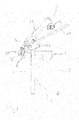
Fig. 1 is a diagrammatical lateral view of an embodiment of an apparatus according to the invention in a start position thereof -
Fig. 2 is a lateral view corresponding to that ofFig. 1 in an end position in which the animal has been fully skinned -
Fig. 3 is a front view of the apparatus shown inFig. 1 -
Fig. 4 is a front view of the apparatus shown inFig. 2 -
Fig. 5 is a perspective view of a section of the apparatus with a body-clamping device and a skin-clamping device in the start position thereof ready to clamp respective portions of an animal to be skinned -
Fig. 6 is a view corresponding to that inFig. 5 with portions of the animal clamped in the respective clamping devices, and -
Fig. 7 is a view corresponding to that inFig. 6 just prior to the finishing of the skinning, the skinned body and the removed skin not being shown. - The embodiment of the skinning apparatus shown in the drawings is arranged for skinning minks which have been cut open along the legs and from which the skin has been loosened and freed from the rear portion of the body, the rear legs and the tail.
- The apparatus comprises a frame 1 having a
front 2, rear 3 a bottom 4 and a top 5, and additionally a body-clampingdevice 6 for clamping thelegs 7 and/or rear portion of the body of the mink and a skin-clampingdevice 8 for clamping the skin portion 9 freed from the body. - The body-clamping
device 6 is accessible from the front in a clamping and start position thereof shown inFigs. 1 ,3 ,5 and6 and arranged in an upper portion of the apparatus. The body-clamping device comprises a lower body-clamping jaw 10 and an upper moveable body-clamping jaw 11 movable between an open position shown inFigs. 1 ,3 and4 and a closed position shown inFig. 6 , and where it appears that thelegs 7 have been clamped. The body-clamping device is arranged movably between the start position shown inFigs. 1 ,3 ,4 and6 and an end position shown inFigs. 2 and4 in which the body freed from the skin is discharged. The body-clamping device is moveable along alinear track 12 comprising a linear guide and a chain drive extending upwardly and rearward. Alower chain wheel 13 of the chain drive is visible inFigs. 3 ,4 and7 . - An upper chain wheel is driven by a
motor 14. Thebody clamping device 6 and thelinear track 12 is covered by a downwardly open screen 16 allowing the skinned body be to discharged to aconveyer belt 17 arranged beneath thelinear track 12 when the skinned body is released from the body-clampingdevice 6 in the end position thereof shown inFigs. 2 and4 or another position between the start position and the end position. The chain drive including the motor is arranged for stopping the body-clampingdevice 6 at any preselected position between the start and the end position. Additionally the chain drive is arranged to move the body-clampingdevice 6 with at least two different speeds from the lower body clamping position and the upper discharge position, comprising a first speed and a second speed, the first speed being higher than the second speed and being preferably used during the first part of the skinning, the second speed being preferably used during the last more difficult part of the skinning. - The skin-clamping
device 8 for clamping the skin freed from the body is arranged at a firstouter end 18 of aswivel arm 19, asecond end 20 thereof being pivotally connected to the frame 1. - By means of the
swivel arm 19, the skin-clampingdevice 8 is pivotal between a clamping and start position shown inFigs. 1 ,3 ,5 and6 in which it is accessible at thefront 2 and positioned in close proximity to the body-clampingdevice 6 and an end position shown inFigs. 2 and4 and in which the skin has been completely separated from the body. A drive for driving theswivel arm 19 is provided with stop means for stopping the pivotal movement of the arm at adjustable positions between the start and clamping position and the end position. Additionally, the drive of the swivel arm is arranged for pivoting the arm with at least two different speeds from the start position to the end position or an intermediate position comprising a first speed and a second speed, the first speed being higher than the second speed and being preferably used during the first part of the skinning, the second lower speed being preferably used during last more difficult skinning of the shoulder and head area of the animal. - The skin-clamping
device 8 comprises an upper fixedjaw 21 connected to the swivel arm and a lowerdisplaceable jaw 22 being displaceably connected to the swivel arm. Thedisplaceable jaw 22 is linear displaceable away from and toward towards the fixedjaw 21 between an open position and a closed clamping position. In the open position, the spacing between the upper and lower jaw allows the previously loosened and freed skin portion to be inserted between the jaws and subsequently clamped between the jaws. - The upper fixed
jaw 21 is a forwardly open jaw comprising a pair of arms 23a, 23b being shaped to define a forwardly open cavity 24 with a forwardly facing opening 25 and having alower clamping face 26. The inner cavity is defined by aninner surface 27 and shaped and dimensioned to receive the body portion being freed from skin through the opening 25. The cavity 24 of the upper fixedjaw 21 is preferably dimensioned so that the inner surface thereof engages at least lateral portions of the body when the body is received in the cavity. In the embodiment shown, the upper fixed jaw is essentially V-shaped as most clearly shown inFigs. 3 ,4 and7 . - The lower
displaceable jaw 22 is a forwardly open jaw comprising a pair of arms 28a, 28b being shaped to define a forwardly open cavity 29 with a forwardly facingopening 30 and having anupper clamping face 31. The cavity 29 of thelower jaw 22 is defined by aninner surface 32 and shaped and dimensioned to receive the body portion not being freed from skin through the opening. Preferably and in the embodiment shown, the cavity 29 of thelower jaw 22 is dimensioned so that theinner surface 32 thereof engages at least lateral portions of the not skinned body when the body is received in the cavity 29. In the embodiment shown, the lower jaw 23 has an essentially V-shaped cross section and theinner surface 32 thereof formed by the arms thereof is elongated as seen in the displacement direction of the lower jaw. The inner surface thereby forms a support face for a body received in the cavity 29. - As clearly seen in
Fig. 1 , the skin-clampingdevice 8 and thereby also thelower jaw 22 is sloping upwardly and rearward towards the body-clampingdevice 6. Additionally, it can be seen fromFig. 1 that ahorizontal roller 33 for supporting the body during the skinning is connected with the frame between the start position of the body-clampingdevice 6 and the start position of the skin-clampingdevice 8. - Reference is made to
Figs. 1 ,3 ,5 and6 . As it appears, atail clamp 34 for clamping the tail skin freed from the body is pivotally connected to the firstouter end 18 of theswivel arm 19 by means of atail clamp arm 35. By means of thetail clamp arm 35, thetail clamp 34 is pivotal between a tail-clamping position in which the tail skin is clamped between clamp jaws 36, 37 of the tail clamp, as shown inFig. 6 , and a rest position or inactive position in which the tail clamp is positioned laterally outside a vertical area defined by the openings of the jaws of the skin-clamping device, as shown inFigs. 3 and5 . The tail clamps 36, 37 are an upper fixed jaw 36 having a lower clamp face 38 and a lower moveable jaw 37 having anupper clamp face 39 and being moveable between an open and a closed position. In the clamping position of the tail clamp, the lower clamp face 38 of the upper clamp jaw 36 is positioned in a plane formed by thelower clamping face 26 of theupper fixes jaw 21 of the skin-clampingdevice 8. The pivotal connection of the tail clamp arm to the swivel is preferably arranged to move the lower clamp face 38 in the plane defined by thelower clamping face 26 of the upper fixedjaw 21 of the skin-clamping device. Further, in the clamping position,tail clamp 34 is positioned essentially directly in front of opening of theupper jaw 21 of the skin-clamping device. - Further and as especially shown in
Figs. 2 ,3 ,4 , and7 , the apparatus comprises anadditional device 40 arranged at a level between the body-clampingdevice 6 and theskin clamping device 8 in the start positions thereof. The additional clamping device comprises two clampingjaws Figs. 3 ,5 and6 , in which they do not interfere with the positioning or skinning of a mink to be skinned and a closed position in which the jaws clamp the body of the mink being skinned at the shoulder area of the front legs during skinning of the head region of the mink. The clamping position is shown inFigs. 4 and7 , however, the skinned body and the skin not being shown. - The apparatus operates as follows:
- A mink is provided which has been cut open and from which the skin portion has been loosened and freed from the rear portion of the body and the rear legs and the tail.
- In the start positions of the body-clamping
device 6 and the skin-clampingdevice 8 shown inFigs. 1 ,3 and5 , the mink is arranged in the said devices with the back facing forwardly. Thelegs 7 are clamped in the body-clamping device as illustrated inFigs. 5 and6 . - Then, the body portion freed from skin is arranged in the cavity of the upper jaw of the skin-clamping
device 8, the freed skin portion is arranged in the opening between thejaws device 8 and the portion of the mink not freed from skin is arranged in the cavity of thelower jaw 22 of the skin-clampingdevice 8 as shown inFig. 3 . - Additionally, the
tail clamp 34 is now pivoted into its tail-clamping position and the tail skin 43 is arranged between the jaws 36,37 thereof. Subsequently, the skin-clampingdevice 8 and thetail clamp 34 are closed as shown inFig. 6 . In this position, thebody clamp 6 is moved upwardly along thetrack 12 and the swivel arm, and thereby the skin-clamping device is pivoted downwards. As a result of the above mentioned movement, the distance between the body-clamping device and the skin-clamping device is gradually increased and the mink thereby gradually skinned. When the skin has been drawn off to the point adjacent the head, the additional clamping device is activated and the shoulder area of the body clamped whereupon the reminder portion of the mink is skinned. - The first portion of the skinning advantageously takes place at a higher speed than the last part.
- After skinning, the skinned body is dislodged onto the
conveyer belt 17, the separated skin released from the skin-clampingdevice 8 and the tail clamp. Thereupon the different clamping devices are moved into the start positions thereof. The apparatus is then ready for skinning an additional mink. -
- 1
- frame
- 2
- front
- 3
- rear
- 4
- bottom
- 5
- top
- 6
- body-clamping device
- 7
- legs
- 8
- skin-clamping device
- 9
- freed skin portion
- 10
- lower body-clamping jaw
- 11
- upper moveable body-clamping jaw
- 12
- linear track
- 13
- lower chain wheel
- 14
- drive motor
- 16
- screen
- 17
- belt conveyer
- 18
- first outer end
- 19
- swivel arm
- 20
- second end
- 21
- upper fixed jaw
- 22
- lower displaceable jaw
- 23a,23b
- arm of fixed jaw
- 24
- cavity of fixed jaw
- 25
- opening of fixed jaw
- 26
- lower clamping face
- 27
- inner surface of fixed jaw
- 28a, 28b
- arms of lower jaw
- 29
- cavity of lower jaw
- 30
- opening of lower jaw
- 31
- upper clamping face
- 32
- inner surface of lower jaw
- 33
- horizontal roller
- 34
- tail clamp
- 35
- tail clamp arm
- 36
- clamp jaw
- 37
- clamp jaw
- 38
- lower clamp face
- 39
- upper clamp face
- 40
- additional clamping device
- 41
- clamping jaw
- 42
- clamping jaw
- 43
- tail skin
Claims (14)
- A skinning apparatus for skinning fur animals, especially minks, which have been cut open along and between the legs and from which the skin has been loosened and freed from the rear portion of the body and the rear legs and the tail, said apparatus comprising- a frame (1) having a front (2), a rear (3), a top( 5) and a bottom (4)- a body-clamping device (6) for clamping said legs (7) and/or rear portion of the body freed for the skin in a start and body-clamping position and being accessible at the front,- a skin clamping device (8) for clamping the skin freed from the body and being by means of a skin moving means arranged for a downwardly and rearwardly movement of the skin-clamping device (8) between an upper start and skin-clamping position and a lower position at a distance from the upper skin-clamping position and in which the skin has been completely separated from the body,- the skin-clamping device (8) being in the upper skin-clamping position positioned adjacent to the body-clamping device (6) and being accessible at the front,characterised in that- the skin-clamping device (8) comprises an upper fixed jaw (21) and a lower displaceable jaw (22) being displaceable away from and towards the fixed jaw (21) between an open position and a closed clamping position- the upper fixed jaw (21) is a forwardly open jaw comprising a pair of optionally mutually connected arms (23a,23b) shaped to define a forwardly open cavity (24) with a forwardly facing opening (25) and having a lower clamping face (26) and an inner surface (27) defining the forwardly open cavity shaped and dimensioned to receive the body portion freed from skin- the lower displaceable jaw (22) is a forwardly open jaw comprising a pair of optionally mutually connected arms (28a,28b) shaped to define a forwardly open cavity (29) with a forwardly facing opening (30) and having an upper clamping face (31) and an inner surface (32) defining the forwardly open cavity shaped and dimensioned to receive the body portion not being freed from skin- the upper clamping surface (31) of the lower displaceable jaw(22) is in the open position thereof spaced from the lower clamping surface (26) of the upper fixed jaw (21) to receive the freed skin portion between said clamping faces.
- Apparatus according to claim 1, wherein the skin moving means comprises a swivel arm (19), the skin-clamping device (8) being arranged at a first end (18) of the swivel arm (19), a second end (20) of the swivel arm being pivotally connected to the frame (1), said skin-clamping device (8) being by means of the swivel arm pivotal between the upper start and skin-clamping position and the lower position, and the upper fixed jaw (21) being connected to the swivel arm (19) and the lower displaceable arm (22) being displaceably connected to the swivel arm.
- Apparatus according to claim 1, wherein the skin moving means comprises a conveyer, a chain drive and/or a track to which the skin-clamping device is connected.
- Apparatus according to any of the preceding claims, wherein the cavity of the lower displaceable jaw (22) is shaped and dimensioned so that the inner surface (32) thereof engages at least opposite lateral portions of the body not freed from skin when the body is received in the cavity.
- Apparatus according to any of the preceding claims, wherein the cavity (24) of the fixed jaw (21) is shaped and dimensioned so that the inner surface (27) thereof engages at least lateral portions of the body when the body is received in the cavity.
- Apparatus according to any of the preceding claims, wherein the arms (28a,28b) of the lower displaceable jaw (22) of the skin-clamping device (8) are elongated arms providing an elongated inner surface (32) as seen in the displacement direction thereof, said inner surface providing a support face for a body received in the cavity defined by the elongated arms.
- Apparatus according to any of the preceding claims, wherein the apparatus, optionally the skin-clamping device thereof, is provided with a tail clamp (34) for clamping the freed skin of the tail (43) of a body received in the skin clamping device (8), the tail clamp being arranged movably between a tail-clamping position in which the tail is clamped between the jaws of the tail clamp and a rest position or inactive position in which the tail clamp (34) is positioned laterally outside a vertical area defined by the openings (25;30) of the skin clamping device (8).
- Apparatus according to claim 7, wherein the tail clamp (34) is arranged at a first end of an tail clamp arm (35), a second end of the tail clamp arm being arranged pivotally relative to the skin-clamping device (8), the tail clamp (34) being, by means of the tail clamp arm (35), pivotal between the inactive or rest position and the tail-clamping position.
- Apparatus according to any of the claims 7 and 8, wherein the tail-clamping position is in a plane essentially defined by the lower clamping face (26) of the upper fixed jaw (21) of the skin-clamping device (8) and the tail clamp (34) arranged to clamp the tail (43) in said plane and preferably in a position essentially directly in front of the opening (25) of the upper jaw (21) of the skin clamping device (8).
- Apparatus according to any of the preceding claims, wherein the apparatus comprises a body movement means (12,13,14) cooperating with or being a part of the body-clamping device (6) for providing an upwardly and rearwardly movement of the body clamped therein between the clamping position and a discharge position where the completely freed skin is discharged.
- Apparatus according to claim 10, wherein the body movement means is arranged to move the body-clamping device with at least two different speeds from the clamping position to the discharge position, comprising a first speed and a second speed, the first speed being higher than the second speed.
- Apparatus according to any of the claims 10 and 11, wherein the body movement means comprises stop means for slowing down, and/or interrupting or stopping the movement of the body-clamping device (6) at one or more adjustable positions between the clamping position and the discharge position.
- Apparatus according to any of the preceding claims, wherein the skin moving means is arranged to move the skin-clamping device (8) with at least two different speeds from the upper start position to the lower end position comprising a first predefined speed and a second predefined speed, the first predefined speed being higher than the second predefined speed.
- Apparatus according to any of the preceding claims, wherein the skin moving means is provided with stop means for slowing down and/or interrupting or stopping the movement of the skin-clamping device at one or more adjustable positions between the upper start and skin clamping position and the lower end position.
Priority Applications (1)
| Application Number | Priority Date | Filing Date | Title |
|---|---|---|---|
| PL15152997T PL2901861T3 (en) | 2014-02-03 | 2015-01-29 | Skinning apparatus |
Applications Claiming Priority (1)
| Application Number | Priority Date | Filing Date | Title |
|---|---|---|---|
| DK201400059A DK178204B1 (en) | 2014-02-03 | 2014-02-03 | Skinning apparatus |
Publications (2)
| Publication Number | Publication Date |
|---|---|
| EP2901861A1 true EP2901861A1 (en) | 2015-08-05 |
| EP2901861B1 EP2901861B1 (en) | 2017-08-02 |
Family
ID=52395012
Family Applications (1)
| Application Number | Title | Priority Date | Filing Date |
|---|---|---|---|
| EP15152997.1A Active EP2901861B1 (en) | 2014-02-03 | 2015-01-29 | Skinning apparatus |
Country Status (3)
| Country | Link |
|---|---|
| EP (1) | EP2901861B1 (en) |
| DK (2) | DK178204B1 (en) |
| PL (1) | PL2901861T3 (en) |
Cited By (2)
| Publication number | Priority date | Publication date | Assignee | Title |
|---|---|---|---|---|
| WO2017032455A1 (en) * | 2015-08-27 | 2017-03-02 | Eikon Technologies Holding S.À.R.L. | Apparatus for skinning bodies of furred animals |
| WO2018011084A1 (en) * | 2016-07-15 | 2018-01-18 | Eikon Technologies Holding S.À.R.L. | Apparatus and method for releasing the skin from an animal body of a furred animal |
Families Citing this family (1)
| Publication number | Priority date | Publication date | Assignee | Title |
|---|---|---|---|---|
| DK179135B1 (en) * | 2016-07-15 | 2017-11-27 | Eikon Tech Holding S À R L | Apparatus and method for releasing the skin from an animal body of a furred animal |
Citations (4)
| Publication number | Priority date | Publication date | Assignee | Title |
|---|---|---|---|---|
| US3046597A (en) * | 1959-05-28 | 1962-07-31 | Hormel & Co Geo A | Machine for removing hides from slaughter animals and the like |
| US3443275A (en) * | 1966-11-29 | 1969-05-13 | Dennis L Radtke | Mink skinning machine |
| EP0894437A1 (en) * | 1997-07-25 | 1999-02-03 | Peis Maskinfabrik A/S | Apparatus for skinning fur-bearing animals |
| US20080081548A1 (en) * | 2004-09-29 | 2008-04-03 | Millers Mechanical (Nz) Limited | Apparatus and Method for Mechanical Removal of Pelt from an Animal Carcass |
Family Cites Families (5)
| Publication number | Priority date | Publication date | Assignee | Title |
|---|---|---|---|---|
| DK165768C (en) * | 1989-02-17 | 1993-06-14 | Soeren Daniel Soerensen | APPARATUS FOR FELTING OF FUR ANIMALS, EX. MINK AND RAEVE |
| DK174847B1 (en) * | 1998-12-04 | 2003-12-22 | Gjoel Pelsningsredskaber As | Method and apparatus for removing skin from pelt animal body where skin is freed from rear legs and involves skinned part of body inserted between pair of belt or chain conveyors whilst freed skin edge is drawn in opposite direction |
| DK175689B1 (en) * | 2003-03-24 | 2005-01-17 | 4M Globe Man Ltd | Apparatus for removal of pelt from pelt animal comprises frame with work surface on which is installed a movable clamping device together with a holding device |
| DK176580B1 (en) * | 2007-02-21 | 2008-10-06 | 4M Globe Man Ltd | Apparatus for fur coat, in particular mink |
| FI121524B (en) * | 2009-04-30 | 2010-12-31 | Norcar Bsb Ab Oy | Pelting Machine |
-
2014
- 2014-02-03 DK DK201400059A patent/DK178204B1/en not_active IP Right Cessation
-
2015
- 2015-01-29 PL PL15152997T patent/PL2901861T3/en unknown
- 2015-01-29 EP EP15152997.1A patent/EP2901861B1/en active Active
- 2015-01-29 DK DK15152997.1T patent/DK2901861T3/en active
Patent Citations (4)
| Publication number | Priority date | Publication date | Assignee | Title |
|---|---|---|---|---|
| US3046597A (en) * | 1959-05-28 | 1962-07-31 | Hormel & Co Geo A | Machine for removing hides from slaughter animals and the like |
| US3443275A (en) * | 1966-11-29 | 1969-05-13 | Dennis L Radtke | Mink skinning machine |
| EP0894437A1 (en) * | 1997-07-25 | 1999-02-03 | Peis Maskinfabrik A/S | Apparatus for skinning fur-bearing animals |
| US20080081548A1 (en) * | 2004-09-29 | 2008-04-03 | Millers Mechanical (Nz) Limited | Apparatus and Method for Mechanical Removal of Pelt from an Animal Carcass |
Cited By (3)
| Publication number | Priority date | Publication date | Assignee | Title |
|---|---|---|---|---|
| WO2017032455A1 (en) * | 2015-08-27 | 2017-03-02 | Eikon Technologies Holding S.À.R.L. | Apparatus for skinning bodies of furred animals |
| PL424627A1 (en) * | 2015-08-27 | 2019-08-26 | Eikon Technologies Holding S.A.R.L. | Device for skinning fur animal bodies |
| WO2018011084A1 (en) * | 2016-07-15 | 2018-01-18 | Eikon Technologies Holding S.À.R.L. | Apparatus and method for releasing the skin from an animal body of a furred animal |
Also Published As
| Publication number | Publication date |
|---|---|
| PL2901861T3 (en) | 2018-01-31 |
| DK2901861T3 (en) | 2017-11-13 |
| DK201400059A1 (en) | 2015-08-10 |
| EP2901861B1 (en) | 2017-08-02 |
| DK178204B1 (en) | 2015-08-17 |
Similar Documents
| Publication | Publication Date | Title |
|---|---|---|
| EP2901861B1 (en) | Skinning apparatus | |
| EP1491096A1 (en) | Apparatus for automatically removing a tail from poultry | |
| WO2009139032A1 (en) | Deboning method and deboning device of arm part or leg part | |
| CA2864989C (en) | Device and method for separating a fatty structure connected to an intestine from the intestine by means of cutting | |
| EP3051955B1 (en) | A skinning device for removing skin from an animal carcass part when conveyed by a conveyor means | |
| AU2007334749B2 (en) | Puller for use in animal carcass boning or cutting | |
| CN103153071B (en) | The method that the device of the cube meat that automation processing transmits continuously and this device are implemented | |
| JPWO2007129409A1 (en) | Method and apparatus for peeling skinned partial meat, and cutter apparatus | |
| CA2994037C (en) | System and method for automatically loosening or removing shoulder blades from shoulder of carcasses | |
| JPH01312962A (en) | Boner | |
| NO135850B (en) | ||
| US3995350A (en) | Method and an apparatus for cleaving slaughtered carcasses | |
| US20220408740A1 (en) | A slaughtered pig part processing plant with a pig part deskinner, and a slaughtered pig part deskinner unit | |
| AU2010229463B2 (en) | A method and device for automatic removal of animal carcass knuckle tips | |
| US3553767A (en) | Hide peeler | |
| CA2449868C (en) | Method and apparatus for use in removal of internal bones in a fore-end | |
| KR20150058700A (en) | Gizzard Cutter for Chichen | |
| DK176580B1 (en) | Apparatus for fur coat, in particular mink | |
| CA2742218C (en) | Apparatus and method for automated cutting of the wings from poultry bodies | |
| JP2019149953A (en) | Lobster extending tool and lobster extending device | |
| US20230371533A1 (en) | Crustacean butchering apparatus | |
| DK178858B1 (en) | Apparatus for skinning bodies of furred animals | |
| KR20220120194A (en) | Device for Removing Eyes of Squid | |
| NZ552206A (en) | Puller for use in animal carcass boning or cutting constrained for substantially downwards movement | |
| TH167502A (en) | Poultry Tenderloin Puller Tool |
Legal Events
| Date | Code | Title | Description |
|---|---|---|---|
| PUAI | Public reference made under article 153(3) epc to a published international application that has entered the european phase |
Free format text: ORIGINAL CODE: 0009012 |
|
| 17P | Request for examination filed |
Effective date: 20150129 |
|
| AK | Designated contracting states |
Kind code of ref document: A1 Designated state(s): AL AT BE BG CH CY CZ DE DK EE ES FI FR GB GR HR HU IE IS IT LI LT LU LV MC MK MT NL NO PL PT RO RS SE SI SK SM TR |
|
| AX | Request for extension of the european patent |
Extension state: BA ME |
|
| 17P | Request for examination filed |
Effective date: 20160203 |
|
| RBV | Designated contracting states (corrected) |
Designated state(s): AL AT BE BG CH CY CZ DE DK EE ES FI FR GB GR HR HU IE IS IT LI LT LU LV MC MK MT NL NO PL PT RO RS SE SI SK SM TR |
|
| GRAP | Despatch of communication of intention to grant a patent |
Free format text: ORIGINAL CODE: EPIDOSNIGR1 |
|
| RIC1 | Information provided on ipc code assigned before grant |
Ipc: A22B 5/16 20060101AFI20170217BHEP |
|
| INTG | Intention to grant announced |
Effective date: 20170313 |
|
| GRAS | Grant fee paid |
Free format text: ORIGINAL CODE: EPIDOSNIGR3 |
|
| GRAA | (expected) grant |
Free format text: ORIGINAL CODE: 0009210 |
|
| AK | Designated contracting states |
Kind code of ref document: B1 Designated state(s): AL AT BE BG CH CY CZ DE DK EE ES FI FR GB GR HR HU IE IS IT LI LT LU LV MC MK MT NL NO PL PT RO RS SE SI SK SM TR |
|
| REG | Reference to a national code |
Ref country code: CH Ref legal event code: EP Ref country code: AT Ref legal event code: REF Ref document number: 913444 Country of ref document: AT Kind code of ref document: T Effective date: 20170815 |
|
| REG | Reference to a national code |
Ref country code: IE Ref legal event code: FG4D |
|
| REG | Reference to a national code |
Ref country code: DE Ref legal event code: R096 Ref document number: 602015003792 Country of ref document: DE |
|
| REG | Reference to a national code |
Ref country code: DK Ref legal event code: T3 Effective date: 20171108 |
|
| REG | Reference to a national code |
Ref country code: NL Ref legal event code: MP Effective date: 20170802 |
|
| REG | Reference to a national code |
Ref country code: AT Ref legal event code: MK05 Ref document number: 913444 Country of ref document: AT Kind code of ref document: T Effective date: 20170802 |
|
| REG | Reference to a national code |
Ref country code: LT Ref legal event code: MG4D |
|
| PG25 | Lapsed in a contracting state [announced via postgrant information from national office to epo] |
Ref country code: AT Free format text: LAPSE BECAUSE OF FAILURE TO SUBMIT A TRANSLATION OF THE DESCRIPTION OR TO PAY THE FEE WITHIN THE PRESCRIBED TIME-LIMIT Effective date: 20170802 Ref country code: SE Free format text: LAPSE BECAUSE OF FAILURE TO SUBMIT A TRANSLATION OF THE DESCRIPTION OR TO PAY THE FEE WITHIN THE PRESCRIBED TIME-LIMIT Effective date: 20170802 Ref country code: FI Free format text: LAPSE BECAUSE OF FAILURE TO SUBMIT A TRANSLATION OF THE DESCRIPTION OR TO PAY THE FEE WITHIN THE PRESCRIBED TIME-LIMIT Effective date: 20170802 Ref country code: HR Free format text: LAPSE BECAUSE OF FAILURE TO SUBMIT A TRANSLATION OF THE DESCRIPTION OR TO PAY THE FEE WITHIN THE PRESCRIBED TIME-LIMIT Effective date: 20170802 Ref country code: NO Free format text: LAPSE BECAUSE OF FAILURE TO SUBMIT A TRANSLATION OF THE DESCRIPTION OR TO PAY THE FEE WITHIN THE PRESCRIBED TIME-LIMIT Effective date: 20171102 Ref country code: LT Free format text: LAPSE BECAUSE OF FAILURE TO SUBMIT A TRANSLATION OF THE DESCRIPTION OR TO PAY THE FEE WITHIN THE PRESCRIBED TIME-LIMIT Effective date: 20170802 Ref country code: NL Free format text: LAPSE BECAUSE OF FAILURE TO SUBMIT A TRANSLATION OF THE DESCRIPTION OR TO PAY THE FEE WITHIN THE PRESCRIBED TIME-LIMIT Effective date: 20170802 |
|
| PG25 | Lapsed in a contracting state [announced via postgrant information from national office to epo] |
Ref country code: RS Free format text: LAPSE BECAUSE OF FAILURE TO SUBMIT A TRANSLATION OF THE DESCRIPTION OR TO PAY THE FEE WITHIN THE PRESCRIBED TIME-LIMIT Effective date: 20170802 Ref country code: LV Free format text: LAPSE BECAUSE OF FAILURE TO SUBMIT A TRANSLATION OF THE DESCRIPTION OR TO PAY THE FEE WITHIN THE PRESCRIBED TIME-LIMIT Effective date: 20170802 Ref country code: BG Free format text: LAPSE BECAUSE OF FAILURE TO SUBMIT A TRANSLATION OF THE DESCRIPTION OR TO PAY THE FEE WITHIN THE PRESCRIBED TIME-LIMIT Effective date: 20171102 Ref country code: ES Free format text: LAPSE BECAUSE OF FAILURE TO SUBMIT A TRANSLATION OF THE DESCRIPTION OR TO PAY THE FEE WITHIN THE PRESCRIBED TIME-LIMIT Effective date: 20170802 Ref country code: IS Free format text: LAPSE BECAUSE OF FAILURE TO SUBMIT A TRANSLATION OF THE DESCRIPTION OR TO PAY THE FEE WITHIN THE PRESCRIBED TIME-LIMIT Effective date: 20171202 Ref country code: GR Free format text: LAPSE BECAUSE OF FAILURE TO SUBMIT A TRANSLATION OF THE DESCRIPTION OR TO PAY THE FEE WITHIN THE PRESCRIBED TIME-LIMIT Effective date: 20171103 |
|
| PG25 | Lapsed in a contracting state [announced via postgrant information from national office to epo] |
Ref country code: CZ Free format text: LAPSE BECAUSE OF FAILURE TO SUBMIT A TRANSLATION OF THE DESCRIPTION OR TO PAY THE FEE WITHIN THE PRESCRIBED TIME-LIMIT Effective date: 20170802 Ref country code: RO Free format text: LAPSE BECAUSE OF FAILURE TO SUBMIT A TRANSLATION OF THE DESCRIPTION OR TO PAY THE FEE WITHIN THE PRESCRIBED TIME-LIMIT Effective date: 20170802 |
|
| REG | Reference to a national code |
Ref country code: DE Ref legal event code: R097 Ref document number: 602015003792 Country of ref document: DE |
|
| PG25 | Lapsed in a contracting state [announced via postgrant information from national office to epo] |
Ref country code: SM Free format text: LAPSE BECAUSE OF FAILURE TO SUBMIT A TRANSLATION OF THE DESCRIPTION OR TO PAY THE FEE WITHIN THE PRESCRIBED TIME-LIMIT Effective date: 20170802 Ref country code: EE Free format text: LAPSE BECAUSE OF FAILURE TO SUBMIT A TRANSLATION OF THE DESCRIPTION OR TO PAY THE FEE WITHIN THE PRESCRIBED TIME-LIMIT Effective date: 20170802 Ref country code: SK Free format text: LAPSE BECAUSE OF FAILURE TO SUBMIT A TRANSLATION OF THE DESCRIPTION OR TO PAY THE FEE WITHIN THE PRESCRIBED TIME-LIMIT Effective date: 20170802 Ref country code: IT Free format text: LAPSE BECAUSE OF FAILURE TO SUBMIT A TRANSLATION OF THE DESCRIPTION OR TO PAY THE FEE WITHIN THE PRESCRIBED TIME-LIMIT Effective date: 20170802 |
|
| PLBE | No opposition filed within time limit |
Free format text: ORIGINAL CODE: 0009261 |
|
| STAA | Information on the status of an ep patent application or granted ep patent |
Free format text: STATUS: NO OPPOSITION FILED WITHIN TIME LIMIT |
|
| 26N | No opposition filed |
Effective date: 20180503 |
|
| REG | Reference to a national code |
Ref country code: DE Ref legal event code: R119 Ref document number: 602015003792 Country of ref document: DE |
|
| PG25 | Lapsed in a contracting state [announced via postgrant information from national office to epo] |
Ref country code: SI Free format text: LAPSE BECAUSE OF FAILURE TO SUBMIT A TRANSLATION OF THE DESCRIPTION OR TO PAY THE FEE WITHIN THE PRESCRIBED TIME-LIMIT Effective date: 20170802 |
|
| REG | Reference to a national code |
Ref country code: CH Ref legal event code: PL |
|
| PG25 | Lapsed in a contracting state [announced via postgrant information from national office to epo] |
Ref country code: DE Free format text: LAPSE BECAUSE OF NON-PAYMENT OF DUE FEES Effective date: 20180801 Ref country code: FR Free format text: LAPSE BECAUSE OF NON-PAYMENT OF DUE FEES Effective date: 20180131 Ref country code: LU Free format text: LAPSE BECAUSE OF NON-PAYMENT OF DUE FEES Effective date: 20180129 |
|
| REG | Reference to a national code |
Ref country code: IE Ref legal event code: MM4A |
|
| REG | Reference to a national code |
Ref country code: FR Ref legal event code: ST Effective date: 20180928 |
|
| REG | Reference to a national code |
Ref country code: BE Ref legal event code: MM Effective date: 20180131 |
|
| PG25 | Lapsed in a contracting state [announced via postgrant information from national office to epo] |
Ref country code: BE Free format text: LAPSE BECAUSE OF NON-PAYMENT OF DUE FEES Effective date: 20180131 Ref country code: LI Free format text: LAPSE BECAUSE OF NON-PAYMENT OF DUE FEES Effective date: 20180131 Ref country code: CH Free format text: LAPSE BECAUSE OF NON-PAYMENT OF DUE FEES Effective date: 20180131 |
|
| PG25 | Lapsed in a contracting state [announced via postgrant information from national office to epo] |
Ref country code: IE Free format text: LAPSE BECAUSE OF NON-PAYMENT OF DUE FEES Effective date: 20180129 |
|
| PG25 | Lapsed in a contracting state [announced via postgrant information from national office to epo] |
Ref country code: MC Free format text: LAPSE BECAUSE OF FAILURE TO SUBMIT A TRANSLATION OF THE DESCRIPTION OR TO PAY THE FEE WITHIN THE PRESCRIBED TIME-LIMIT Effective date: 20170802 |
|
| GBPC | Gb: european patent ceased through non-payment of renewal fee |
Effective date: 20190129 |
|
| PG25 | Lapsed in a contracting state [announced via postgrant information from national office to epo] |
Ref country code: GB Free format text: LAPSE BECAUSE OF NON-PAYMENT OF DUE FEES Effective date: 20190129 |
|
| PG25 | Lapsed in a contracting state [announced via postgrant information from national office to epo] |
Ref country code: MT Free format text: LAPSE BECAUSE OF NON-PAYMENT OF DUE FEES Effective date: 20180129 |
|
| PG25 | Lapsed in a contracting state [announced via postgrant information from national office to epo] |
Ref country code: TR Free format text: LAPSE BECAUSE OF FAILURE TO SUBMIT A TRANSLATION OF THE DESCRIPTION OR TO PAY THE FEE WITHIN THE PRESCRIBED TIME-LIMIT Effective date: 20170802 |
|
| PG25 | Lapsed in a contracting state [announced via postgrant information from national office to epo] |
Ref country code: PT Free format text: LAPSE BECAUSE OF FAILURE TO SUBMIT A TRANSLATION OF THE DESCRIPTION OR TO PAY THE FEE WITHIN THE PRESCRIBED TIME-LIMIT Effective date: 20170802 |
|
| PG25 | Lapsed in a contracting state [announced via postgrant information from national office to epo] |
Ref country code: HU Free format text: LAPSE BECAUSE OF FAILURE TO SUBMIT A TRANSLATION OF THE DESCRIPTION OR TO PAY THE FEE WITHIN THE PRESCRIBED TIME-LIMIT; INVALID AB INITIO Effective date: 20150129 Ref country code: CY Free format text: LAPSE BECAUSE OF FAILURE TO SUBMIT A TRANSLATION OF THE DESCRIPTION OR TO PAY THE FEE WITHIN THE PRESCRIBED TIME-LIMIT Effective date: 20170802 Ref country code: MK Free format text: LAPSE BECAUSE OF NON-PAYMENT OF DUE FEES Effective date: 20170802 |
|
| PG25 | Lapsed in a contracting state [announced via postgrant information from national office to epo] |
Ref country code: AL Free format text: LAPSE BECAUSE OF FAILURE TO SUBMIT A TRANSLATION OF THE DESCRIPTION OR TO PAY THE FEE WITHIN THE PRESCRIBED TIME-LIMIT Effective date: 20170802 |
|
| PGFP | Annual fee paid to national office [announced via postgrant information from national office to epo] |
Ref country code: DK Payment date: 20221213 Year of fee payment: 9 |
|
| PGFP | Annual fee paid to national office [announced via postgrant information from national office to epo] |
Ref country code: PL Payment date: 20230103 Year of fee payment: 9 |