EP2901624B1 - Adjustment of the bandwidth of a data stream in a shared xdsl virtual channel - Google Patents
Adjustment of the bandwidth of a data stream in a shared xdsl virtual channel Download PDFInfo
- Publication number
- EP2901624B1 EP2901624B1 EP13779262.8A EP13779262A EP2901624B1 EP 2901624 B1 EP2901624 B1 EP 2901624B1 EP 13779262 A EP13779262 A EP 13779262A EP 2901624 B1 EP2901624 B1 EP 2901624B1
- Authority
- EP
- European Patent Office
- Prior art keywords
- network
- gateway
- service
- access
- xdsl
- Prior art date
- Legal status (The legal status is an assumption and is not a legal conclusion. Google has not performed a legal analysis and makes no representation as to the accuracy of the status listed.)
- Active
Links
- 238000000034 method Methods 0.000 claims description 20
- 238000004590 computer program Methods 0.000 claims description 11
- 238000004891 communication Methods 0.000 claims description 10
- 238000011144 upstream manufacturing Methods 0.000 claims description 10
- 238000013500 data storage Methods 0.000 claims 1
- 101150012579 ADSL gene Proteins 0.000 description 23
- 102100020775 Adenylosuccinate lyase Human genes 0.000 description 23
- 108700040193 Adenylosuccinate lyases Proteins 0.000 description 23
- 238000005516 engineering process Methods 0.000 description 15
- 230000006870 function Effects 0.000 description 6
- 238000012360 testing method Methods 0.000 description 6
- 230000008901 benefit Effects 0.000 description 5
- 238000012546 transfer Methods 0.000 description 4
- 238000004458 analytical method Methods 0.000 description 3
- 230000009467 reduction Effects 0.000 description 3
- 230000004044 response Effects 0.000 description 3
- 230000001360 synchronised effect Effects 0.000 description 3
- 230000005540 biological transmission Effects 0.000 description 2
- 238000006243 chemical reaction Methods 0.000 description 2
- 230000001276 controlling effect Effects 0.000 description 2
- 238000011156 evaluation Methods 0.000 description 2
- 230000007246 mechanism Effects 0.000 description 2
- 230000003287 optical effect Effects 0.000 description 2
- 230000003213 activating effect Effects 0.000 description 1
- 230000004913 activation Effects 0.000 description 1
- 238000004422 calculation algorithm Methods 0.000 description 1
- 230000001143 conditioned effect Effects 0.000 description 1
- 238000013461 design Methods 0.000 description 1
- 239000000284 extract Substances 0.000 description 1
- 230000004907 flux Effects 0.000 description 1
- 238000004377 microelectronic Methods 0.000 description 1
- 238000011176 pooling Methods 0.000 description 1
- 238000012545 processing Methods 0.000 description 1
- 230000001105 regulatory effect Effects 0.000 description 1
- 230000011664 signaling Effects 0.000 description 1
- 238000001228 spectrum Methods 0.000 description 1
Images


Classifications
-
- H—ELECTRICITY
- H04—ELECTRIC COMMUNICATION TECHNIQUE
- H04M—TELEPHONIC COMMUNICATION
- H04M11/00—Telephonic communication systems specially adapted for combination with other electrical systems
- H04M11/06—Simultaneous speech and data transmission, e.g. telegraphic transmission over the same conductors
- H04M11/062—Simultaneous speech and data transmission, e.g. telegraphic transmission over the same conductors using different frequency bands for speech and other data
-
- H—ELECTRICITY
- H04—ELECTRIC COMMUNICATION TECHNIQUE
- H04L—TRANSMISSION OF DIGITAL INFORMATION, e.g. TELEGRAPHIC COMMUNICATION
- H04L47/00—Traffic control in data switching networks
- H04L47/70—Admission control; Resource allocation
- H04L47/80—Actions related to the user profile or the type of traffic
- H04L47/805—QOS or priority aware
Definitions
- the present invention relates to xDSL networks using ATM technology. More particularly, the present invention relates to a method and a device for adjusting the bandwidth of a data stream within a virtual channel pooling several data streams associated with different services.
- Asynchronous Transfer Mode is a frame switching network protocol (called "cells"), which makes it possible to multiplex on the same link different time division multiplexing (TDM) data streams, offering several levels of Quality of Service (“ Quality of Service " or QoS).
- TDM time division multiplexing
- ATM technology has been designed to provide a unified network standard that could carry both synchronous data traffic and traffic using packets (eg, IP type). More precisely, ATM is an asynchronous protocol, usually based on a synchronous transport layer: ATM cells are sent asynchronously, depending on the data to be transmitted, but are inserted into the synchronous data stream. a lower level protocol for their transport.
- ATM cells are fixed-size data segments of 53 bytes (48 bytes of payload and 5 bytes of header), unlike variable length packets used for example in IP type protocols ("Internet Protocol ”) or Ethernet.
- Cell switching combines the simplicity of circuit switching with the flexibility of packet switching.
- a virtual circuit is established either by configuration of the equipment or by signaling, and the successive cells are switched on this virtual circuit by switching labels.
- the path used in the network by these cells does not vary during the communication since it is determined during the establishment of the virtual circuit.
- ATM is a fairly complex technology, but its functionality applies to both large telecommunications networks and Local Area Networks (LANs), which are smaller in size.
- LANs Local Area Networks
- ATM is useful and widely deployed as a multiplexing layer in xDSL networks, where its compromises are well suited to the needs of these networks.
- ADSL initials of English words Asymmetrical Digital Subscriber Line ( " Asymmetric Digital Subscriber Line ") is a technology that uses the conventional telephone lines of the Public Switched Telephone Network (PTC) to convey data at a high speed. debit.
- ADSL technology was initially defined in the International Telecommunication Union (ITU) standard G.992.1 and in the American National Standards Institute (ANSI) standard T1.413. It has been extended to a set of technologies collectively called "xDSL" (such as ADSL, ADSL2, ADSL2 +, SDSL, VDSL and VDSL2), all of which are encompassed by the present invention.
- ITU International Telecommunication Union
- ANSI American National Standards Institute
- ADSL technology takes advantage of frequency bands not used by the RTC. Thus, while the voice is transported over a frequency band ranging from 300 to 3400 Hz, the ADSL signal is transmitted over high (inaudible) frequency ranges from about 26 kHz to about 2 MHz. The use of this very wide band makes it possible to transport data at rates up to 8 Mbit / s in reception, and 768 kbit / s in transmission; In this respect, it should be noted that Internet communications are generally very asymmetrical: for example, a consumer-user connected to the Internet needs a considerable amount of data in reception, whereas in transmission, a low data rate is generally sufficient. . ADSL technology is adapted to these needs, since it offers both high and asymmetrical throughput.
- a filter separates in the residence of the user, among the received signals, those which correspond to the telephone communications of the high frequency signals.
- the conversion of digital data into analog signals in ADSL uses Frequency Division Multiplexing (FDM).
- FDM Frequency Division Multiplexing
- DMT Frequency Division Multiplexing
- the most commonly used standard is called DMT (initials of the words “ Discrete Multi Tone “ meaning “ Discrete Multi-Tones ”) and is defined in the aforementioned G.992.1 standard.
- the available frequency range is divided into a predetermined number (256 or 512) of subchannels (also called “tones”).
- DMT implements a large number of "virtual modems", which are responsible for controlling each subchannel; these virtual modems collaborate to carry digital data at high speeds.
- a modem (modulator / demodulator) performs the digital-to-analog conversion mentioned above, and conversely, data from the ADSL line.
- This modem is often integrated in a residential gateway 1, which manages a local network of devices belonging to a subscriber within a domestic residence, or a company.
- a residential gateway 1 which manages a local network of devices belonging to a subscriber within a domestic residence, or a company.
- VoIP Voice over IP
- a core network equipment called “configuration server” 5 allows the ADSL operator to configure the gateway 1, that is to say, to set operating parameters of the local network and the ADSL line.
- the gateway 1 is connected to a DSLAM (initials of the words “Digital Subscriber Line Access Multiplexer “ meaning “Digital Subscriber Line Access Multiplexer ”) 4: it is a device located at the central office and collecting ADSL data traffic that travels over a number of telephone lines.
- DSLAM digital Subscriber Line Access Multiplexer
- the link establishment phase between the gateway 1 and the DSLAM 4 is called “synchronization”. and “sync rate” the data rate between these two units.
- the synchronization rate is conventionally set according to a protocol that will be described below (it is said that the synchronization rate is "negotiated" between the gateway 1 and the DSLAM 4 ").
- the DSLAM 4 filters this signal.
- the "analog voice” part is sent by a filter card to the RTC, and the ADSL part to a modem card.
- the upper part of the frequency spectrum is demodulated: we are at this point with the ATM signal as it was before being modulated in ADSL subscriber.
- the ATM virtual channels restored by the DSLAM 4 modem card are multiplexed, by means of a network card, to form access paths. virtual ( "virtual Path” or VP in English) or to the Internet service providers ( “Service providers", or SP, in English).
- the figure 1b represents a particular case of conventional ADSL network.
- This network is similar to that of the figure 1a , except that each VP started in DSLAM 4 is routed over the ATM path to a node in the network called " Broadband Access Server " (BAS). , which performs IP routing, subscriber authentication and evaluation of data traffic volumes.
- BAS 7 is a point of concentration of the flows exchanged between the subscriber, and the Internet or service platforms; VPs are terminated in BAS 7, and each VC is individually processed to allow connection to a service platform; BAS 7 hosts “virtual routers", which direct subscriber data flows to an IP network that provides access to service platforms.
- the BAS 7 is therefore an equipment of the ADSL network which interfaces the ATM collection network with the network of interconnection (" Backbone Network " in English) and IP collection; it should be noted however that the BAS 7 does not know a priori which bit rate has been negotiated between the gateway 1 and the DSLAM 4, in particular in the case of so-called "free-flow" offers in which the bandwidth offered to the customer is the maximum bandwidth that could be negotiated on the ADSL link.
- Wi-Fi is a wireless communication technology defined by the IEEE 802.11 standard. Electric and Electronics Engineers).
- This service consists of offering xDSL subscribers the opportunity to allow other subscribers of the same operator to access their residential hotspot .
- the xDSL subscriber who agrees to participate in this system will in return receive a free Internet connectivity service while on the move, via the ability to connect to the community Wi-Fi network created by all participating hotspots. .
- QoS Quality of Service
- the common solution to solve this bandwidth guarantee problem is to use different virtual channels for each service, by defining specific service classes assigned to each VC, such as CBR ( Constant Bit Rate ), VBR ( Variable Bit Rate). ), UBR ( Unspecified Bite Rate ) or ABR ( Available Bit Rate ).
- CBR Constant Bit Rate
- VBR Variable Bit Rate
- UBR Unspecified Bite Rate
- ABR Available Bit Rate
- interface is meant here the place of termination of a connection, seen from said access gateway, for example a certain IP address, or a certain couple IP address / VLAN (initials of the words " Virtual Local Area Network” Meaning “Virtual Local Network”).
- the present invention proposes to limit, as a function of a synchronization rate on the xDSL line associated with an access gateway (and, optionally, according to additional criteria), the flow of a data stream from a service platform and intended for this gateway, during the passage of this data stream through a device according to the invention, called "hub node", preferably located in the heart of said IP network.
- Said value of the synchronization rate may conventionally be negotiated between the access gateway and the xDSL network.
- the access gateway targeted by the invention may be a residential gateway used in the context of a home or business, or another type of gateway giving access to an xDSL network.
- the invention is simple to implement, and does not require to have complex functionalities on said hub node.
- said service targeted by said access request is a non-priority service with respect to a predetermined service, called priority service, said priority service being associated with data streams passing through the same virtual channel as those of the service. non-priority service, but not passing through said hub node.
- the invention can convey the Internet connectivity service of a visitor on the Internet VC of the priority subscriber, while ensuring to this priority subscriber that the activation of a "public hotspot " function on its residential gateway will not disturb the bandwidth reserved for it by more than a certain percentage (the said percentage being to be fixed contractually between the subscriber priority and its xDSL provider).
- a terminal sends an access request to a gateway in response to an announcement signal, called " beacon ", issued by the gateway; thus, by activating, or not, on this gateway a beacon signal corresponding to the community Wi-Fi service, it is possible to control the possibility for non-priority subscribers to present a request for access to the network via this gateway; this control can for example be useful in the case where it is found that the synchronization rate is so low that it is not even enough to accommodate the target bandwidth of the priority subscriber: in this case, we obviously do not want allow non-priority subscribers to use the gateway, and therefore will not broadcast this beacon signal .
- non-priority service can, as in the example of community Wi-Fi, concern another subscriber than the priority service, it can equally well concern the same subscriber as the priority service by being, obviously , assigned a lower priority.
- the invention relates to various devices.
- the gateway may further comprise means for negotiating with the xDSL network said value of the synchronization rate.
- said access gateway further comprises means for determining whether said service targeted by said access request is a predetermined service, called priority service, or another service, called non-priority service, and for not implement the means described briefly above only if it is a non-priority service.
- the invention also relates, secondly, an equipment, said hub node, of an IP network, comprising a plurality of interfaces.
- Said hub node is remarkable in that it further comprises means for receiving, when a given interface of said hub node receives a request for access to a service sent by a user of an xDSL network contained in said IP network, route the traffic, said downstream traffic, for this user through said interface having received the access request, and in that each of these interfaces carries a limiting function to limit the flow of said downstream traffic.
- the invention also relates to an IP network comprising at least one access gateway and a hub node as briefly described above.
- the figure 2a schematically represents an xDSL network according to one embodiment of the invention (network without BAS), and the figure 2b schematically represents an xDSL network according to another embodiment of the invention (network with BAS).
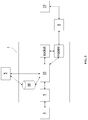
- the figure 3 schematically represents the hardware architecture of a gateway, as well as certain units connected to this gateway, according to one embodiment of the invention.
- the Figures 2a , 2b and 3 show in particular equipment, called “hub node" 10, whose functions will be explained below.
- the residential gateway 1, the telephone 2 and the personal computer 3 belong to a subscriber called “priority subscriber”, and another subscriber of the same operator xDSL or a partner operator, called “non-subscriber”.
- priority presents a request to access remote service platforms by communicating via said gateway 1.
- This access request may for example be sent by the non-priority subscriber from a laptop 8 provided with a Wi-Fi transmitter / receiver.
- HTTP HyperText Transfer Protocol
- DNS Domain Name System
- IPv4 or IPv6 address allocation request according to the Dynamic Host Configuration Protocol (DHCP) or the Neighbor Discovery protocol.
- DHCP Dynamic Host Configuration Protocol
- step E1 the access request is received by a Wi-Fi hotspot 9 (not shown on the Figures 2a and 2b ) contained in Gateway 1, and transmitted to a management unit 20 (not shown on the Figures 2a and 2b ) of the gateway 1.
- step E3 the management unit 20 issues a request for consultation to a database 30 (not shown on the Figures 2a and 2b ) fed by said configuration server 5 and which is preferably contained in the gateway 1.
- This consultation request contains the value of the synchronization rate as well as, optionally, other information such as, in particular, the bit rates for other services using the same xDSL line, carried on other VCs in the line than the VC used by the "non-priority" service and requiring guaranteed bandwidth.
- the management unit 20 receives from the database 30 the identity of a certain corresponding interface of the hub node 10.
- the hub node 10 is provided with a plurality of interfaces, each of these interfaces carrying a predetermined bandwidth limiting function making it possible to limit the outgoing flow of the concentrator node 10 towards the gateway 1.
- 10 interfaces may be provided, and the outgoing traffic from each of the interfaces of the hub node 10 may be conditioned to a specific rate value, which will be between 0.5 Mbps and 5 Mbps (for example 0.5 Mbps, 1 Mbps, 1.5 Mbps, 2 Mbps, ..., 5 Mbps).
- the database 30 contains a correspondence table which has been filled in by the configuration server 5. This table matches respective information comprising at least one synchronization rate value to the identity of a respective interface of the concentrator node 10.
- the data in this table result from a calculation algorithm to determine the value V at which the non-priority stream traffic must be clipped, and hence the appropriate interface on the hub node 10.
- said value V may be taken as x % of the synchronization rate (where the number x , with 0 ⁇ x ⁇ 100, is set by the operator), which will ensure that the non-priority service can only access a bounded proportion of the total bandwidth of the xDSL line; it is also possible to take into account the bandwidth required for the guaranteed rate services using the same xDSL line but carried on the other VCs of the line, which means that the value V will be reduced accordingly.
- step E4 the gateway 1 transmits the access request upstream of the xDSL / IP network, using as the destination address the address of said corresponding interface of the hub node 10 provided by the database 30.
- the gateway 1 includes a " socket " responsible for IP addressing.
- step E5 a routing context is created at the hub node 10 during the upstream passage of the access request, so that (in case of acceptance of the access request by the IP network) the downstream traffic associated with the non-priority subscriber passes through the corresponding interface of the hub node 10.
- the streams transmitted by the portable computer 8 pass through the gateway 1, the VC 6, the DSLAM 4, and the selected interface of the concentrator node 10, before being routed to their destination (Internet or service platform). , while the streams received by the laptop 8 follow the opposite path.
- the flows exchanged also pass through a BAS 7. Note that only the flows of the user (or users) non-priority (s) pass through the hub node 10, while all flows (priority, or not -priorities) go through the same VC 6. If others non-priority subscribers are allowed to access the same VC, their streams will follow the same path as for the first non-priority subscriber.
- the invention proposes that, when passing, in the uplink direction, a request for access to a service accessible via an xDSL network, a routing context is created at the hub node 10 when it is desired that the downstream traffic associated with this access request passes through an appropriate interface of this hub node 10.
- the routing context may contain the external address of the gateway 1 and / or the source address of the access request.
- the access request is inserted in a tunnel to the appropriate interface on the hub node 10.
- the source address of the tunnel is the external address of the gateway 1
- the destination address of the tunnel is the address of the appropriate interface on the hub node 10.
- the hub node 10 extracts the access request from the tunnel, and relays it to the service platform without changing the address Source IP.
- the traffic passes through the hub node 10, it suffices to announce to the part of the IP network connecting the hub node 10 to the service platform the route to the range of addresses of the clients managed by the hub node 10.
- the associated proxies can be connected to the hub node 10 via one or more private networks constructed such that each proxy is reachable from the gateway 1 only by a single interface of the hub node 10; for this purpose, the address of each proxy must be advertised on the IP network between the gateway 1 and the concentration node 10 as being accessible via a particular interface of the concentration node 10; in the downstream direction, the traffic can be routed in this private network from a given proxy to the interface of the hub node 10 to which this proxy is associated, either via a default route, or by l announcing a route to the address range of the gateways or IP clients managed by this interface of the hub node 10 (and, optionally, other hub nodes, which will advantageously make it possible to use several hub nodes); we can advantageously allocate private addresses to the IP clients intended to receive the streams coming from a service platform and passing through a hub node 10 bypassing the NAT device between this hub node 10 and the service platform; it will be noted that in the case of this second arrangement, the management
- a proxy is also used in gateway 1 (in addition to the associated proxies just mentioned).
- the access request is then intercepted by the gateway proxy , which then relays this access request by replacing the destination address with the proxy address associated with the appropriate interface on the hub node 10.
- the source address of the access request may be further replaced by the external address of the gateway 1.
- the invention can be implemented within the nodes of an IP network, for example gateways or hubs, by means of software and / or hardware components.
- the present invention also relates to a computer system.
- This computer system conventionally comprises a central processing unit controlling signals by a memory, as well as an input unit and an output unit.
- this computer system may be used to execute a computer program having instructions for implementing any of the bandwidth adjustment methods of the invention.
- the invention also relates to a downloadable computer program from a communication network comprising instructions for executing the steps of a bandwidth adjustment method according to the invention, when it is executed on a computer.
- This computer program may be stored on a computer readable medium and may be executable by a microprocessor.
- This program can use any programming language, and be in the form of source code, object code, or intermediate code between source code and object code, such as in a partially compiled form, or in any another desirable form.
- the information carrier may be any entity or device capable of storing the program.
- the medium may comprise storage means, such as a ROM, for example a CD ROM or a microelectronic circuit ROM, or a magnetic recording medium, such as a hard disk, or a USB key. (" USB flash drive" in English).
- the information medium may be a transmissible medium such as an electrical or optical signal, which may be conveyed via an electrical or optical cable, by radio or by other means.
- the computer program according to the invention can in particular be downloaded to an Internet type network.
- the information carrier may be an integrated circuit in which the program is embedded, the circuit being adapted to execute or to be used in the performance of any of the bandwidth adjustment methods according to the present invention. invention.
Landscapes
- Engineering & Computer Science (AREA)
- Computer Networks & Wireless Communication (AREA)
- Signal Processing (AREA)
- Data Exchanges In Wide-Area Networks (AREA)
Description
La présente invention concerne les réseaux xDSL utilisant la technologie ATM. Plus particulièrement, la présente invention concerne un procédé et un dispositif pour ajuster la bande passante d'un flux de données au sein d'un canal virtuel mutualisant plusieurs flux de données associés à différents services.The present invention relates to xDSL networks using ATM technology. More particularly, the present invention relates to a method and a device for adjusting the bandwidth of a data stream within a virtual channel pooling several data streams associated with different services.
On rappelle (cf. par exemple le site Internet http://.fr.wikipedia.org/wiki/Asynchronous Transfer Mode) que la technologie ATM (initiales des mots anglais « Asynchronous Transfer Mode » signifiant « Mode de Transfert Asynchrone ») est un protocole réseau à commutation de trames (appelées « cellules »), qui permet de multiplexer sur un même lien différents flots de données par répartition dans le temps (« Time Division Multiplexing », ou TDM en anglais), en offrant plusieurs niveaux de Qualité de Service (« Quality of Service », ou QoS en anglais).It is recalled (see for example the website http: //.fr.wikipedia.org/wiki/Asynchronous Transfer Mode ) that the ATM technology (initials of the words "Asynchronous Transfer Mode" meaning " Asynchronous Transfer Mode ") is a frame switching network protocol (called "cells"), which makes it possible to multiplex on the same link different time division multiplexing (TDM) data streams, offering several levels of Quality of Service (" Quality of Service " or QoS).
La technologie ATM a été conçue pour fournir un standard réseau unifié qui pourrait transporter aussi bien un trafic de données synchrone qu'un trafic utilisant des paquets (par exemple, de type IP). Plus précisément, l'ATM est un protocole asynchrone, s'appuyant habituellement sur une couche de transport synchrone : en effet, les cellules ATM sont envoyées de manière asynchrone, en fonction des données à transmettre, mais sont insérées dans le flux de données synchrones d'un protocole de niveau inférieur pour leur transport.ATM technology has been designed to provide a unified network standard that could carry both synchronous data traffic and traffic using packets (eg, IP type). More precisely, ATM is an asynchronous protocol, usually based on a synchronous transport layer: ATM cells are sent asynchronously, depending on the data to be transmitted, but are inserted into the synchronous data stream. a lower level protocol for their transport.
Les cellules ATM sont des segments de données de taille fixe de 53 octets (48 octets de charge utile et 5 octets d'en-tête), à la différence des paquets de longueur variable utilisés par exemple dans les protocoles de type IP (« Internet Protocol ») ou Ethernet. La commutation des cellules allie la simplicité de la commutation de circuits à la flexibilité de la commutation de paquets. Pour chaque communication, un circuit virtuel (« virtual circuit », ou VC en anglais) est établi soit par configuration des équipements, soit par signalisation, et les cellules successives sont commutées sur ce circuit virtuel par commutation de labels. En particulier, le chemin utilisé dans le réseau par ces cellules ne varie pas au cours de la communication puisqu'il est déterminé lors de l'établissement du circuit virtuel.ATM cells are fixed-size data segments of 53 bytes (48 bytes of payload and 5 bytes of header), unlike variable length packets used for example in IP type protocols ("Internet Protocol ") or Ethernet. Cell switching combines the simplicity of circuit switching with the flexibility of packet switching. For each communication, a virtual circuit (VC) is established either by configuration of the equipment or by signaling, and the successive cells are switched on this virtual circuit by switching labels. In particular, the path used in the network by these cells does not vary during the communication since it is determined during the establishment of the virtual circuit.
L'ATM est une technologie assez complexe, mais dont les fonctionnalités s'appliquent aussi bien aux grands réseaux de télécommunications qu'aux Réseaux Locaux (« Local Area Networks », ou LAN en anglais) de dimensions plus réduites. L'ATM est utile et largement déployé comme couche de multiplexage dans les réseaux xDSL, où ses compromis correspondent bien aux besoins de ces réseaux.ATM is a fairly complex technology, but its functionality applies to both large telecommunications networks and Local Area Networks (LANs), which are smaller in size. ATM is useful and widely deployed as a multiplexing layer in xDSL networks, where its compromises are well suited to the needs of these networks.
On rappelle également (cf. par exemple l'article correspondant sur le site Internet www.kitz.co.uk, ou l'étude présentée par Jean Parrend à la société France Télécom en juin 2004) que l'ADSL (initiales des mots anglais « Asymmetrical Digital Subscriber Line » signifiant « Ligne d'Abonné Numérique Asymétrique ») est une technologie utilisant les lignes téléphoniques classiques du Réseau Téléphonique Commuté (RTC) (« Public Switched Telephone Network, ou PSTN, en anglais) pour véhiculer des données à haut débit. La technologie ADSL a été initialement définie dans la norme G.992.1 de l'Union Internationale des Télécommunications (International Telecommunication Union ou ITU en anglais), ainsi que dans la norme T1.413 de l'ANSI (American National Standards Institute). Elle a été étendue à un ensemble de technologies collectivement appelées « xDSL » (telles que ADSL, ADSL2, ADSL2+, SDSL, VDSL et VDSL2), qui sont toutes visées par la présente invention.It is also recalled (see for example the corresponding article on the website www.kitz.co.uk , or the study presented by Jean Parrend to France Telecom in June 2004) that ADSL (initials of English words Asymmetrical Digital Subscriber Line ( " Asymmetric Digital Subscriber Line ") is a technology that uses the conventional telephone lines of the Public Switched Telephone Network (PTC) to convey data at a high speed. debit. ADSL technology was initially defined in the International Telecommunication Union (ITU) standard G.992.1 and in the American National Standards Institute (ANSI) standard T1.413. It has been extended to a set of technologies collectively called "xDSL" (such as ADSL, ADSL2, ADSL2 +, SDSL, VDSL and VDSL2), all of which are encompassed by the present invention.
La technologie ADSL tire parti des bandes de fréquences non utilisées par le RTC. Ainsi, alors que la voix est transportée sur une bande de fréquences allant de 300 à 3400 Hz, le signal ADSL est transmis sur des plages de fréquences hautes (inaudibles) allant de 26 kHz à 2 MHz environ. L'utilisation de cette bande très large permet de transporter des données à des débits pouvant atteindre au maximum 8 Mbit/s en réception, et 768 kbit/s en émission ; on notera à cet égard que les communications sur Internet sont généralement très asymétriques : par exemple, un utilisateur grand public connecté à l'Internet a besoin d'un débit assez considérable en réception, tandis qu'en émission, un débit faible lui suffit généralement. La technologie ADSL est adaptée à ces besoins, puisqu'elle offre un débit à la fois élevé et asymétrique.ADSL technology takes advantage of frequency bands not used by the RTC. Thus, while the voice is transported over a frequency band ranging from 300 to 3400 Hz, the ADSL signal is transmitted over high (inaudible) frequency ranges from about 26 kHz to about 2 MHz. The use of this very wide band makes it possible to transport data at rates up to 8 Mbit / s in reception, and 768 kbit / s in transmission; In this respect, it should be noted that Internet communications are generally very asymmetrical: for example, a consumer-user connected to the Internet needs a considerable amount of data in reception, whereas in transmission, a low data rate is generally sufficient. . ADSL technology is adapted to these needs, since it offers both high and asymmetrical throughput.
Point intéressant pour l'utilisateur, comme les signaux vocaux et ADSL utilisent des plages de fréquences différentes, la même ligne téléphonique permet, simultanément, de téléphoner et de « surfer » sur Internet avec un débit élevé. Un filtre sépare dans la résidence de l'utilisateur, parmi les signaux reçus, ceux qui correspondent aux communications téléphoniques des signaux de hautes fréquences.Interesting for the user, as voice and ADSL signals use different frequency ranges, the same telephone line allows simultaneous phone calls and "surfing" on the Internet at high speed. A filter separates in the residence of the user, among the received signals, those which correspond to the telephone communications of the high frequency signals.
La conversion de données numériques en signaux analogiques dans l'ADSL utilise un multiplexage par division en fréquence (« Frequency Division Multiplexing », ou FDM en anglais). Il existe différentes méthodes de modulation, mais la norme la plus utilisée est appelée DMT (initiales des mots anglais « Discrete Multi Tone » signifiant « Multi-Tonalités Discrètes ») et est définie dans la norme G.992.1 précitée. Selon la norme DMT, la gamme de fréquences disponibles est divisée en un nombre prédéterminé (256 ou 512) de sous-canaux (également appelés « tonalités »). DMT met en oeuvre un grand nombre de « modems virtuels », qui sont responsables du contrôle de chaque sous-canal ; ces modems virtuels collaborent pour transporter les données numériques à des vitesses élevées.The conversion of digital data into analog signals in ADSL uses Frequency Division Multiplexing (FDM). There are different modulation methods, but the most commonly used standard is called DMT (initials of the words " Discrete Multi Tone " meaning " Discrete Multi-Tones ") and is defined in the aforementioned G.992.1 standard. According to the DMT standard, the available frequency range is divided into a predetermined number (256 or 512) of subchannels (also called "tones"). DMT implements a large number of "virtual modems", which are responsible for controlling each subchannel; these virtual modems collaborate to carry digital data at high speeds.
On va décrire à présent brièvement, en référence à la
Un modem (modulateur/démodulateur) effectue la conversion numérique-vers-analogique mentionnée ci-dessus, et inversement, des données de la ligne ADSL. Ce modem est souvent intégré dans une passerelle résidentielle 1, qui gère un réseau local de dispositifs appartenant à un abonné au sein d'une résidence domestique, ou d'une entreprise. On a représenté ici, à titre d'exemple, un poste téléphonique analogique 2 et un ordinateur personnel 3 connectés à la passerelle 1 ; les signaux vocaux émis par ce téléphone 2 sont transformés en signaux de VoIP (Voix sur IP) par la passerelle 1.A modem (modulator / demodulator) performs the digital-to-analog conversion mentioned above, and conversely, data from the ADSL line. This modem is often integrated in a
Un équipement de coeur de réseau appelé « serveur de configuration » 5 permet à l'opérateur ADSL de configurer la passerelle 1, c'est-à-dire de régler des paramètres de fonctionnement du réseau local et de la ligne ADSL.A core network equipment called "configuration server" 5 allows the ADSL operator to configure the
La passerelle 1 est connectée à un DSLAM (initiales des mots anglais « Digital Subscriber Line Access Multiplexer » signifiant « Multiplexeur d'Accès de Ligne d'Abonné Numérique ») 4 : il s'agit d'un dispositif situé au central téléphonique et collectant le trafic de données ADSL qui transite sur un certain nombre de lignes téléphoniques. Comme expliqué ci-dessus, les communications entre la passerelle 1 et le DSLAM 4 sont contenues dans un ou plusieurs canaux virtuels (VC) 6. On appelle « synchronisation » la phase d'établissement du lien entre la passerelle 1 et le DSLAM 4, et « débit de synchronisation » le débit de données entre ces deux unités. Le débit de synchronisation est classiquement fixé conformément à un protocole que l'on décrira ci-après (on dit alors que le débit de synchronisation est « négocié » entre la passerelle 1 et le DSLAM 4 »).The
Suite à la réception d'un signal provenant de l'abonné, le DSLAM 4 filtre ce signal. La partie « voix analogique » est envoyée par une carte filtre vers le RTC, et la partie ADSL vers une carte modem. Au niveau de la carte modem, la partie haute du spectre de fréquence est démodulée : on se retrouve à ce stade avec le signal ATM tel qu'il était avant d'être modulé en ADSL côté abonné. Dans le cas particulier où le réseau de collecte au-delà du DSLAM repose sur la technologie ATM, les canaux virtuels ATM restitués par la carte modem du DSLAM 4 sont multiplexés, au moyen d'une carte réseau, pour former des chemins d'accès virtuels (« Virtual Path », ou VP en anglais) vers l'Internet ou des fournisseurs de services (« Service Providers », ou SP, en anglais).Following receipt of a signal from the subscriber, the
La
Ce réseau est analogue à celui de la
On rappelle enfin que le Wi-Fi est une technologie de communication sans-fil définie par la norme 802.11 de la IEEE (Institute of Electric and Electronics Engineers). De nos jours, les passerelles résidentielles intègrent souvent une station de base Wi-Fi (« hotspot » en anglais) (non représentée sur les
Il a été proposé récemment de faire usage des réseaux xDSL dans le cadre d'un service appelé « Wi-Fi communautaire ». Ce service consiste à proposer aux abonnés xDSL de permettre à d'autres abonnés du même opérateur d'accéder à leur hotspot résidentiel. L'abonné xDSL qui accepte de participer à ce système bénéficie en retour d'un service de connectivité Internet gratuit lorsqu'il est en mobilité, via la possibilité de se connecter sur le réseau Wi-Fi communautaire créé par l'ensemble des hotspots participants. L'impact sur la QoS (initiales des mots anglais « Quality of Service » signifiant « Qualité de Service ») de la participation au Wi-Fi communautaire pour cet abonné xDSL doit cependant être minimal ; autrement dit, il s'agit de perturber le moins possible son propre usage de sa ligne xDSL quand des visiteurs se connectent sur son hotspot. It has recently been proposed to make use of xDSL networks as part of a service called "Community Wi-Fi". This service consists of offering xDSL subscribers the opportunity to allow other subscribers of the same operator to access their residential hotspot . The xDSL subscriber who agrees to participate in this system will in return receive a free Internet connectivity service while on the move, via the ability to connect to the community Wi-Fi network created by all participating hotspots. . The impact on Quality of Service (QoS) of participating in Community Wi-Fi for this xDSL subscriber must, however, be minimal; in other words, it is to disturb as little as possible its own use of its xDSL line when visitors connect to its hotspot.
On cherche donc, dans le cadre du Wi-Fi communautaire, à transporter au moins deux services sur une même infrastructure, et l'on souhaite garantir que la proportion de la bande passante de la ligne ADSL offerte aux services dits « non-prioritaires » soit bornée, afin de pouvoir garantir une bande passante minimale pour les services dits « prioritaires » (ceux associés au propriétaire du hotspot) (dans le cadre du présent document, on utilisera de manière équivalente l'expression « bande passante » et l'expression « débit de données »). Dans ce cas, un mécanisme de gestion de bande passante est nécessaire, notamment au niveau du goulot d'étranglement de l'infrastructure de transport utilisée pour ces services. En effet, dans le cas de services utilisant un réseau xDSL et transportés par une technologie ATM, il existe un goulot d'étranglement dans le sens descendant au niveau du lien entre le DSLAM 4 et la passerelle 1.We are therefore seeking, in the context of Wi-Fi community, to transport at least two services on the same infrastructure, and we want to ensure that the proportion of the bandwidth of the ADSL line offered to services called "non-priority" limited in order to guarantee a minimum bandwidth for so-called "priority" services (those associated with the owner of the hotspot ) (for the purposes of this document, the expression "bandwidth" and the expression "Data rate"). In this case, a bandwidth management mechanism is needed, especially at the bottleneck of the transport infrastructure used for these services. Indeed, in the case of services using an xDSL network and transported by ATM technology, there is a bottleneck downward throttling at the link between DSLAM 4 and
La solution couramment déployée pour résoudre ce problème de garantie de bande passante consiste à utiliser des canaux virtuels différents pour chaque service, en définissant des classes de services spécifiques attribuées à chaque VC, telles que CBR (Constant Bit Rate), VBR (Variable Bit Rate), UBR (Unspecified Bite Rate) ou encore ABR (Available Bit Rate). Toutefois, pour des raisons techniques, opérationnelles ou réglementaires, il se trouve que l'utilisation d'un VC par service n'est pas toujours possible. Il est donc nécessaire de concevoir une solution pour le cas où deux services au moins sont portés par le même VC, et où l'on souhaite garantir, soit que le service dit « non-prioritaire » ne puisse accéder qu'à une proportion bornée de la bande passante totale de la ligne xDSL, soit que la réduction relative (en pourcentage) de bande passante induite par le service non-prioritaire sur le service prioritaire véhiculé par le même VC soit limitée à une valeur maîtrisée par l'opérateur. Or la technologie ATM ne prévoit pas de mécanisme permettant d'identifier un flux par rapport à un autre au sein d'un VC, et encore moins d'appliquer des profils de QoS différents pour chacun de ces flux.The common solution to solve this bandwidth guarantee problem is to use different virtual channels for each service, by defining specific service classes assigned to each VC, such as CBR ( Constant Bit Rate ), VBR ( Variable Bit Rate). ), UBR ( Unspecified Bite Rate ) or ABR ( Available Bit Rate ). However, for technical, operational or regulatory reasons, it turns out that the use of one VC per service is not always possible. It is therefore necessary to design a solution for the case where at least two services are carried by the same VC , and where it is desired to guarantee that the so-called "non-priority" service can only access a limited proportion the total bandwidth of the xDSL line, ie that the relative reduction (in percentage) of bandwidth induced by the non-priority service on the priority service conveyed by the same VC is limited to a value controlled by the operator. However, ATM technology does not provide a mechanism for identifying one stream with respect to another within a VC, let alone applying different QoS profiles for each of these streams.
Un exemple de l'art antérieur se trouve dans
La présente invention concerne donc un procédé d'ajustement de bande passante d'un flux de données au sein d'un canal virtuel xDSL, comprenant une étape de réception, par une passerelle d'accès à un réseau xDSL contenu dans un réseau IP, d'une requête d'accès à un service accessible via ledit réseau xDSL. Ledit procédé est remarquable en ce qu'il comprend ensuite les étapes suivantes :
- ladite passerelle d'accès obtient la valeur d'un débit de synchronisation entre la passerelle d'accès et le réseau xDSL,
- la passerelle d'accès détermine, en fonction d'un ensemble d'informations prédéterminé comprenant au moins ladite valeur du débit de synchronisation, l'identité d'une interface correspondante parmi une pluralité d'interfaces d'un équipement du réseau IP, dit noeud concentrateur, chacune de ces interfaces portant une fonction de limitation permettant de limiter le débit du trafic, dit trafic descendant, sortant de cette interface en direction de la passerelle, ou l'identité d'un serveur mandataire associé à ladite interface correspondante du noeud concentrateur,
- la passerelle d'accès transmet la requête d'accès vers l'amont du réseau IP, en utilisant comme adresse de destination l'adresse de ladite interface correspondante du noeud concentrateur ou l'adresse dudit serveur mandataire associé à cette interface correspondante du noeud concentrateur, et
- un contexte de routage est créé au niveau du noeud concentrateur lors du passage, dans le sens montant, de la requête d'accès, de sorte que le trafic descendant associé à cette requête d'accès passe par ladite interface correspondante du noeud concentrateur.
- said access gateway obtains the value of a synchronization rate between the access gateway and the xDSL network,
- the access gateway determines, according to a predetermined set of information comprising at least said value of the synchronization rate, the identity of a corresponding interface among a plurality of interfaces of a piece of equipment of the IP network, said concentrator node, each of these interfaces carrying a limitation function for limiting the flow of traffic, said downstream traffic, coming out of this interface towards the gateway, or the identity of a proxy server associated with said corresponding interface of the node concentrator,
- the access gateway transmits the access request upstream of the IP network, using as the destination address the address of said corresponding interface of the concentrator node or the address of said proxy server associated with this corresponding interface of the concentrator node , and
- a routing context is created at the hub node during the upstream passage of the access request, so that the downstream traffic associated with this access request passes through the corresponding interface of the hub node.
Par « interface », on entend ici le lieu de terminaison d'une connexion, vu de ladite passerelle d'accès, par exemple une certaine adresse IP, ou un certain couple adresse IP/VLAN (initiales des mots anglais « Virtual Local Area Network » signifiant « Réseau Local Virtuel »).By "interface" is meant here the place of termination of a connection, seen from said access gateway, for example a certain IP address, or a certain couple IP address / VLAN (initials of the words " Virtual Local Area Network" Meaning "Virtual Local Network").
Ainsi, la présente invention propose de limiter, en fonction d'un débit de synchronisation sur la ligne xDSL associée à une passerelle d'accès (et, optionnellement, en fonction de critères supplémentaires), le débit d'un flux de données issu d'une plateforme de services et destiné à cette passerelle, lors du passage de ce flux de données au travers d'un équipement selon l'invention, appelé « noeud concentrateur », de préférence situé dans le coeur dudit réseau IP.Thus, the present invention proposes to limit, as a function of a synchronization rate on the xDSL line associated with an access gateway (and, optionally, according to additional criteria), the flow of a data stream from a service platform and intended for this gateway, during the passage of this data stream through a device according to the invention, called "hub node", preferably located in the heart of said IP network.
Ladite valeur du débit de synchronisation pourra, de manière classique, avoir été préalablement négociée entre la passerelle d'accès et le réseau xDSL.Said value of the synchronization rate may conventionally be negotiated between the access gateway and the xDSL network.
On notera également que la passerelle d'accès visée par l'invention pourra être une passerelle résidentielle utilisée dans le cadre d'un domicile ou d'une entreprise, ou bien un autre type de passerelle donnant accès à un réseau xDSL.Note also that the access gateway targeted by the invention may be a residential gateway used in the context of a home or business, or another type of gateway giving access to an xDSL network.
Grâce à ces dispositions, il n'est pas nécessaire de mettre en place dans le réseau un protocole de commande supplémentaire, ou un serveur de contrôle (« policy server »). De plus, l'invention est simple à mettre en oeuvre, et ne nécessite pas de disposer de fonctionnalités complexes sur ledit noeud concentrateur.Thanks to these provisions, it is not necessary to set up in the network an additional control protocol, or a control server (" policy server "). In addition, the invention is simple to implement, and does not require to have complex functionalities on said hub node.
Selon des caractéristiques particulières, ledit service visé par ladite requête d'accès est un service non-prioritaire par rapport à un service prédéterminé, dit service prioritaire, ledit service prioritaire étant associé à des flux de données passant par le même canal virtuel que ceux du service non-prioritaire, mais ne passant pas par ledit noeud concentrateur.According to particular features, said service targeted by said access request is a non-priority service with respect to a predetermined service, called priority service, said priority service being associated with data streams passing through the same virtual channel as those of the service. non-priority service, but not passing through said hub node.
Grâce à ces dispositions, on peut adapter le débit des flux non-prioritaires en amont du DSLAM de manière à ce que, avantageusement, chacun de ces flux non-prioritaires parvenant au DSLAM ne consomme qu'une proportion bornée de la bande passante disponible sur la ligne xDSL, et que la bande passante disponible pour les flux prioritaires soit, quant à elle, supérieure à un minimum garanti.Thanks to these provisions, it is possible to adapt the bit rate of the non-priority flows upstream of the DSLAM so that, advantageously, each of these non-priority streams reaching the DSLAM consumes only a limited proportion of the bandwidth available on the DSLAM. the xDSL line, and that the bandwidth available for priority flows is higher than a guaranteed minimum.
Concernant l'application de l'invention au service Wi-Fi communautaire, on peut ainsi véhiculer le service de connectivité Internet d'un visiteur sur le VC Internet de l'abonné prioritaire, tout en garantissant à cet abonné prioritaire que l'activation d'une fonction « hotspot public » sur sa passerelle résidentielle ne perturbera pas la bande passante qui lui est réservée de plus d'un certain pourcentage (ledit pourcentage étant à fixer de manière contractuelle entre l'abonné prioritaire et son fournisseur d'accès xDSL). On notera à cet égard que, selon l'état de l'art, un terminal n'envoie une requête d'accès à une passerelle qu'en réponse à un signal d'annonce, dit « beacon », émis par la passerelle ; ainsi, en activant, ou non, sur cette passerelle un signal beacon correspondant au service Wi-Fi communautaire, on peut contrôler la possibilité pour des abonnés non-prioritaires de présenter une requête d'accès au réseau via cette passerelle ; ce contrôle peut par exemple être utile au cas où l'on constate que le débit de synchronisation est tellement faible qu'il ne suffit même pas à accommoder la bande passante cible de l'abonné prioritaire : dans ce cas, on ne voudra évidemment pas permettre à des abonnés non-prioritaires d'utiliser la passerelle, et l'on s'abstiendra donc de diffuser ce signal beacon. Regarding the application of the invention to the community Wi-Fi service, it can convey the Internet connectivity service of a visitor on the Internet VC of the priority subscriber, while ensuring to this priority subscriber that the activation of a "public hotspot " function on its residential gateway will not disturb the bandwidth reserved for it by more than a certain percentage (the said percentage being to be fixed contractually between the subscriber priority and its xDSL provider). Note in this regard that, according to the state of the art, a terminal sends an access request to a gateway in response to an announcement signal, called " beacon ", issued by the gateway; thus, by activating, or not, on this gateway a beacon signal corresponding to the community Wi-Fi service, it is possible to control the possibility for non-priority subscribers to present a request for access to the network via this gateway; this control can for example be useful in the case where it is found that the synchronization rate is so low that it is not even enough to accommodate the target bandwidth of the priority subscriber: in this case, we obviously do not want allow non-priority subscribers to use the gateway, and therefore will not broadcast this beacon signal .
Mais on notera que, si le service non-prioritaire peut, comme dans l'exemple du Wi-Fi communautaire, concerner un autre abonné que le service prioritaire, il peut tout aussi bien concerner le même abonné que le service prioritaire en étant, évidemment, affecté d'un degré de priorité inférieur.But it will be noted that, if the non-priority service can, as in the example of community Wi-Fi, concern another subscriber than the priority service, it can equally well concern the same subscriber as the priority service by being, obviously , assigned a lower priority.
Corrélativement, l'invention concerne divers dispositifs.Correlatively, the invention relates to various devices.
Elle concerne ainsi, premièrement, une passerelle d'accès à un réseau xDSL contenu dans un réseau IP, comprenant des moyens pour recevoir une requête d'accès à un service accessible via ledit réseau xDSL. Ladite passerelle est remarquable en ce qu'elle comprend en outre des moyens pour :
- obtenir la valeur d'un débit de synchronisation entre ladite passerelle d'accès et ledit réseau xDSL,
- déterminer, en fonction d'un ensemble d'informations prédéterminé comprenant au moins ladite valeur du débit de synchronisation, l'identité d'une interface correspondante située dans ledit réseau IP ou l'identité d'un serveur mandataire associé à ladite interface correspondante, et
- transmettre ladite requête d'accès vers l'amont du réseau IP, en utilisant comme adresse de destination l'adresse de ladite interface correspondante ou l'adresse dudit serveur mandataire associé à cette interface correspondante.
- obtain the value of a synchronization rate between said access gateway and said xDSL network,
- determining, based on a predetermined set of information comprising at least said value of the synchronization rate, the identity of a corresponding interface located in said IP network or the identity of a proxy server associated with said corresponding interface, and
- transmitting said access request upstream of the IP network, using as the destination address the address of said corresponding interface or the address of said proxy server associated with this corresponding interface.
La passerelle pourra en outre comprendre des moyens pour négocier avec le réseau xDSL ladite valeur du débit de synchronisation.The gateway may further comprise means for negotiating with the xDSL network said value of the synchronization rate.
Selon des caractéristiques particulières, ladite passerelle d'accès comprend en outre des moyens pour déterminer si ledit service visé par ladite requête d'accès est un service prédéterminé, dit service prioritaire, ou un autre service, dit service non-prioritaire, et pour ne mettre en oeuvre les moyens décrits succinctement ci-dessus que s'il s'agit d'un service non-prioritaire.According to particular features, said access gateway further comprises means for determining whether said service targeted by said access request is a predetermined service, called priority service, or another service, called non-priority service, and for not implement the means described briefly above only if it is a non-priority service.
L'invention concerne aussi, deuxièmement, un équipement, dit noeud concentrateur, d'un réseau IP, comprenant une pluralité d'interfaces. Ledit noeud concentrateur est remarquable en ce qu'il comprend en outre des moyens pour, lors de la réception par une interface donnée dudit noeud concentrateur d'une requête d'accès à un service émise par un utilisateur d'un réseau xDSL contenu dans ledit réseau IP, router le trafic, dit trafic descendant, destiné à cet utilisateur à travers ladite interface ayant reçu la requête d'accès, et en ce que chacune de ces interfaces porte une fonction de limitation permettant de limiter le débit dudit trafic descendant.The invention also relates, secondly, an equipment, said hub node, of an IP network, comprising a plurality of interfaces. Said hub node is remarkable in that it further comprises means for receiving, when a given interface of said hub node receives a request for access to a service sent by a user of an xDSL network contained in said IP network, route the traffic, said downstream traffic, for this user through said interface having received the access request, and in that each of these interfaces carries a limiting function to limit the flow of said downstream traffic.
L'invention vise également un réseau IP comprenant au moins une passerelle d'accès et un noeud concentrateur tels que décrits succinctement ci-dessus.The invention also relates to an IP network comprising at least one access gateway and a hub node as briefly described above.
Les avantages offerts par ces dispositifs et ce réseau IP sont essentiellement les mêmes que ceux offerts par les procédés corrélatifs succinctement exposés ci-dessus.The advantages offered by these devices and this IP network are essentially the same as those offered by the correlative methods briefly described above.
On notera qu'il est possible de réaliser ces dispositifs dans le contexte d'instructions logicielles et/ou dans le contexte de circuits électroniques.Note that it is possible to realize these devices in the context of software instructions and / or in the context of electronic circuits.
L'invention vise également un programme d'ordinateur téléchargeable depuis un réseau de communication et/ou stocké sur un support lisible par ordinateur et/ou exécutable par un microprocesseur. Ce programme d'ordinateur est remarquable en ce qu'il comprend des instructions pour l'exécution des étapes du procédé d'ajustement de bande passante succinctement exposé ci-dessus, lorsqu'il est exécuté sur un ordinateur.The invention also relates to a computer program downloadable from a communication network and / or stored on a computer readable medium and / or executable by a microprocessor. This computer program is notable in that it includes instructions for performing the steps of the bandwidth adjustment method succinctly set forth above, when run on a computer.
Les avantages offerts par ce programme d'ordinateur sont essentiellement les mêmes que ceux offerts par ledit procédé.The advantages offered by this computer program are essentially the same as those offered by said method.
D'autres aspects et avantages de l'invention apparaîtront à la lecture de la description détaillée ci-dessous de modes de réalisation particuliers, donnés à titre d'exemples non limitatifs. La description se réfère aux figures qui l'accompagnent, dans lesquelles :
- la
figure 1 a , déjà décrite ci-dessus, représente schématiquement un réseau ADSL classique, - la
figure 1 b , déjà décrite ci-dessus, représente schématiquement un réseau ADSL classique comprenant un BAS, - la
figure 2a représente schématiquement un réseau xDSL selon un mode de réalisation de l'invention, - la
figure 2b représente schématiquement un réseau xDSL comprenant un BAS, selon un autre mode de réalisation de l'invention, et - la
figure 3 représente schématiquement l'architecture matérielle d'une passerelle, ainsi que certaines unités connectées à cette passerelle, selon un mode de réalisation de l'invention.
- the
figure 1 a , already described above, schematically represents a conventional ADSL network, - the
figure 1b , already described above, schematically represents a conventional ADSL network comprising a BAS, - the
figure 2a schematically represents an xDSL network according to one embodiment of the invention, - the
figure 2b schematically represents an xDSL network comprising a BAS, according to another embodiment of the invention, and - the
figure 3 schematically represents the hardware architecture of a gateway, as well as certain units connected to this gateway, according to one embodiment of the invention.
On va décrire à présent, en référence aux
La
On se place à présent, à titre d'exemple de réalisation, dans le cadre du Wi-Fi communautaire, décrit brièvement ci-dessus.We now turn, as an example of implementation, in the context of community Wi-Fi, briefly described above.
On suppose donc que la passerelle résidentielle 1, le téléphone 2 et l'ordinateur personnel 3 appartiennent à un abonné dit « abonné prioritaire », et qu'un autre abonné du même opérateur xDSL ou d'un opérateur partenaire, dit « abonné non-prioritaire », présente une requête visant à accéder à des plateformes de services distantes en communiquant via ladite passerelle 1. Cette requête d'accès peut par exemple être envoyée par l'abonné non-prioritaire à partir d'un ordinateur portable 8 muni d'un émetteur/récepteur Wi-Fi. Elle peut par exemple être une requête HTTP (« HyperText Transfert Protocol ») vers un serveur Web, ou une requête DNS (« Domain Name System ») de résolution de nom de machine en adresse IP, ou encore une requête d'allocation d'adresse IPv4 ou IPv6 selon le protocole DHCP (« Dynamic Host Configuration Protocol ») ou le protocole « Neighbor Discovery ».It is therefore assumed that the
A l'étape E1, la requête d'accès est reçue par un hotspot Wi-Fi 9 (non représentée sur les
On suppose, dans le présent exemple de réalisation, qu'un débit de synchronisation a été préalablement négocié entre la passerelle 1 et le DSLAM 4 conformément au protocole de synchronisation classique mentionné ci-dessus, et que l'on va décrire à présent.It is assumed in the present embodiment that a synchronization rate has been previously negotiated between the
Ce protocole de synchronisation classique comprend notamment les étapes suivantes :
- i) établissement de la liaison : la passerelle indique au DSLAM quelle version de la technologie xDSL et quels protocoles doivent être utilisés ; en fonction de ces informations, le nombre de sous-canaux est déterminé conformément à la norme DMT (mentionnée ci-dessus) ; le DSLAM détermine ensuite quels sous-canaux seront effectivement utilisés (certains sous-canaux peuvent être écartés pour des raisons de service) ;
- ii) test du modem : évaluation préliminaire de l'atténuation de boucle, test du flux de données, lecture des niveaux de puissance amont, ajustement (en fait, réduction) du niveau de puissance si nécessaire (en effet, on peut avoir à brider la puissance maximale de certains sous-canaux afin de réduire les risques de diaphonie) ;
- iii) analyse des sous-canaux : en réponse aux tests, on analyse l'état de chaque sous-canal ; on lit le niveau de puissance, et l'on calcule le Rapport Signal sur Bruit (« Signal to Noise Ratio », ou SNR, en anglais) et l'atténuation ; ces valeurs déterminent le débit de données pouvant être véhiculé dans chaque sous-canal ; et
- iv) établissement du débit de synchronisation : celui-ci est déterminé par le débit total véhiculé par tous les sous-canaux ; le DSLAM vérifie que le modem peut effectivement recevoir des données à ce débit ; si le modem le confirme, la synchronisation est achevée ; sinon, la procédure d'initialisation est reprise, jusqu'à ce que la synchronisation soit achevée.
- i) link establishment: the gateway tells the DSLAM which version of the xDSL technology and which protocols should be used; based on this information, the number of subchannels is determined according to the DMT standard (mentioned above); the DSLAM then determines which sub-channels will actually be used (some sub-channels may be discarded for service reasons);
- ii) modem test: preliminary evaluation of the loop attenuation, data flow test, reading of the upstream power levels, adjustment (in fact, reduction) of the power level if necessary (indeed, one may have to clamp down the maximum power of some subchannels to reduce the risk of crosstalk);
- iii) subchannel analysis: in response to the tests, the state of each subchannel is analyzed; read the power level, and calculate the Signal to Noise Ratio (SNR) and attenuation; these values determine the data rate that can be carried in each subchannel; and
- iv) establishment of the synchronization rate: this is determined by the total bit rate conveyed by all the subchannels; the DSLAM verifies that the modem can actually receive data at this rate; if the modem confirms it, the synchronization is complete; otherwise, the initialization procedure is resumed until synchronization is complete.
A l'étape E2, ladite unité de gestion 20 obtient la valeur du débit de synchronisation.In step E2, said
A l'étape E3, l'unité de gestion 20 émet une requête de consultation à l'intention d'une base de données 30 (non représentée sur les
En effet, selon l'invention, on munit le noeud concentrateur 10 d'une pluralité d'interfaces, chacune de ces interfaces portant une fonction de limitation de bande passante prédéterminée permettant de limiter le débit sortant du noeud concentrateur 10 en direction de la passerelle 1. Par exemple, on pourra prévoir 10 interfaces, et conditionner le trafic sortant de chacune des interfaces du noeud concentrateur 10 à une valeur de débit spécifique, qui sera comprise entre 0,5 Mbps et 5 Mbps (par exemple 0,5 Mbps, 1 Mbps, 1,5 Mbps, 2 Mbps, ..., 5Mbps).Indeed, according to the invention, the
La base de données 30 contient une table de correspondance qui a été renseignée par le serveur de configuration 5. Cette table fait correspondre des informations respectives comprenant au moins une valeur de débit de synchronisation à l'identité d'une interface respective du noeud concentrateur 10. Les données de cette table résultent d'un algorithme de calcul permettant de déterminer la valeur V à laquelle le trafic du flux non-prioritaire doit être écrêté, et par suite l'interface adéquate sur le noeud concentrateur 10. Par exemple, ladite valeur V pourra être prise égale à x% du débit de synchronisation (où le nombre x, avec 0 ≤ x ≤ 100, est fixé par l'opérateur), ce qui aura pour effet de garantir que le service non-prioritaire ne pourra accéder qu'à une proportion bornée de la bande passante totale de la ligne xDSL ; on pourra optionnellement prendre également en compte la bande passante requise pour les services à débit garanti utilisant cette même ligne xDSL mais véhiculés sur les autres VCs de la ligne, ce qui signifie que la valeur V sera réduite en conséquence.The
A l'étape E4, la passerelle 1 transmet la requête d'accès vers l'amont du réseau xDSL/IP, en utilisant comme adresse de destination l'adresse de ladite interface correspondante du noeud concentrateur 10 fournie par la base de données 30. On notera à cet égard que, de manière classique, la passerelle 1 comporte un « socket » chargé de l'adressage IP.In step E4, the
A l'étape E5, un contexte de routage est créé au niveau du noeud concentrateur 10 lors du passage, dans le sens montant, de la requête d'accès, afin que (en cas d'acceptation de la requête d'accès par le réseau IP) le trafic descendant associé à l'abonné non-prioritaire passe par ladite interface correspondante du noeud concentrateur 10.In step E5, a routing context is created at the
Ainsi, les flux émis par l'ordinateur portable 8 passent par la passerelle 1, le VC 6, le DSLAM 4, et l'interface sélectionnée du noeud concentrateur 10, avant d'être aiguillés vers leur destination (Internet ou plateforme de services), tandis que les flux reçus par l'ordinateur portable 8 suivent le chemin inverse. Dans le mode de réalisation illustré sur la
On s'assure ainsi que les flux descendants associés à l'utilisateur, ou aux utilisateurs, non-prioritaire(s) n'utiliseront au maximum qu'une partie prédéterminée du débit de synchronisation de la ligne xDSL. On pourra prévoir par exemple que l'abonné prioritaire bénéficie d'un débit minimal garanti pour ses services ; en variante, on pourra prévoir que la réduction relative (en pourcentage) de bande passante induite par le(s) service(s) non-prioritaire(s) sur le(s) service(s) prioritaire(s) soit limitée à une valeur maîtrisée par l'opérateur.This ensures that the downstream flows associated with the user or non-priority user (s) will use at most a predetermined portion of the xDSL line synchronization rate. For example, it may be provided that the priority subscriber has a minimum guaranteed bandwidth for his services; alternatively, it can be provided that the relative reduction (in percentage) of bandwidth induced by the non-priority service (s) on the priority service (s) is limited to a value controlled by the operator.
Comme indiqué ci-dessus, l'invention propose que, lors du passage, dans le sens montant, d'une requête d'accès à un service accessible via un réseau xDSL, on crée un contexte de routage au niveau du noeud concentrateur 10 lorsque l'on souhaite que le trafic descendant associé à cette requête d'accès passe par une interface adéquate de ce noeud concentrateur 10. Pour ce faire, diverses variantes de réalisation sont possibles, dans lesquelles le contexte de routage pourra contenir l'adresse externe de la passerelle 1 et/ou l'adresse source de la requête d'accès.As indicated above, the invention proposes that, when passing, in the uplink direction, a request for access to a service accessible via an xDSL network, a routing context is created at the
Ainsi, selon une première variante, on insère la requête d'accès dans un tunnel à destination de l'interface adéquate sur le noeud concentrateur 10. Dans ce cas, l'adresse source du tunnel est l'adresse externe de la passerelle 1, et l'adresse de destination du tunnel est l'adresse de l'interface adéquate sur le noeud concentrateur 10. Le noeud concentrateur 10 extrait la requête d'accès du tunnel, et la relaie vers la plateforme de services sans en modifier l'adresse IP source. Afin de s'assurer que, dans le sens descendant, le trafic passe bien par le noeud concentrateur 10, il suffit d'annoncer à la partie du réseau IP reliant le noeud concentrateur 10 à la plateforme de services la route vers la plage d'adresses des clients gérés par le noeud concentrateur 10. Cette solution est compatible avec l'utilisation d'un dispositif NAT (initiales des mots anglais « Network Address Translator » signifiant « Traducteur d'Adresse Réseau ») situé entre le noeud concentrateur 10 et la plateforme de services, ce dispositif NAT permettant, de manière classique, d'allouer des adresses privées aux clients IP destinés à recevoir les flux passant par le noeud concentrateur 10.Thus, according to a first variant, the access request is inserted in a tunnel to the appropriate interface on the
Selon une deuxième et une troisième variante, on utilise, pour chaque interface du noeud concentrateur 10, un « proxy » (serveur mandataire) associé à cette interface. Chacun de ces proxys associés relaie les requêtes d'accès aux plateformes de service en mettant à la place de l'adresse source de ces requêtes sa propre adresse, qui est annoncée au réseau IP le reliant aux plateformes de services de sorte que le trafic descendant passera par le même proxy que la requête d'accès. Ces proxys associés peuvent, selon un premier agencement, être intégrés dans le noeud concentrateur 10, de sorte que chaque interface du noeud concentrateur est une interface de proxy. Selon un deuxième agencement, les proxys associés peuvent être raccordés au noeud concentrateur 10 via un ou plusieurs réseaux privés construits de telle sorte que chaque proxy ne soit atteignable à partir de la passerelle 1 que par une unique interface du noeud concentrateur 10 ; à cet effet, l'adresse de chaque proxy doit être annoncée sur le réseau IP entre la passerelle 1 et le noeud de concentration 10 comme étant accessible via une interface particulière du noeud de concentration 10 ; dans le sens descendant, le trafic pourra être aiguillé dans ce réseau privé depuis un proxy donné jusqu'à l'interface du noeud concentrateur 10 à laquelle ce proxy est associé, soit par l'intermédiaire d'une route par défaut, soit par l'annonce d'une route vers la plage d'adresse des passerelles ou des clients IP gérés par cette interface du noeud concentrateur 10 (et, optionnellement, d'autres noeuds concentrateurs, ce qui permettra avantageusement d'utiliser plusieurs noeuds concentrateurs) ; on peut ainsi avantageusement allouer des adresses privées aux clients IP destinés à recevoir les flux provenant d'une plateforme de services et passant par un noeud concentrateur 10 en se passant de dispositif NAT entre ce noeud concentrateur 10 et la plateforme de services ; on notera que dans le cas de ce deuxième agencement, l'unité de gestion 20 reçoit de la part de la base de données 30 non pas l'identité de l'interface adéquate du noeud concentrateur 10, mais l'identité du proxy associé à cette interface.According to a second and a third variant, a "proxy " ( proxy server) associated with this interface is used for each interface of the
Plus précisément, dans ladite deuxième variante, on utilise en outre un proxy dans la passerelle 1 (en plus des proxys associés que l'on vient de mentionner). La requête d'accès est alors interceptée par le proxy de la passerelle, qui relaie ensuite cette requête d'accès en y remplaçant l'adresse de destination par l'adresse du proxy associé à l'interface adéquate sur le noeud concentrateur 10. Optionnellement, l'adresse source de la requête d'accès peut être en outre remplacée par l'adresse externe de la passerelle 1.More precisely, in said second variant, a proxy is also used in gateway 1 (in addition to the associated proxies just mentioned). The access request is then intercepted by the gateway proxy , which then relays this access request by replacing the destination address with the proxy address associated with the appropriate interface on the
Dans ladite troisième variante, enfin, on place un dispositif NAT dans la passerelle 1. La requête d'accès transite par le NAT, qui remplace, d'une part, l'adresse de destination en l'adresse du proxy associé à l'interface adéquate sur le noeud concentrateur 10. Optionnellement, l'adresse source de la requête d'accès peut être en outre remplacée par l'adresse externe de la passerelle 1 ; dans ce dernier cas, le port UDP/TCP source de la requête d'accès peut lui aussi être changé.In said third variant, finally, a NAT device is placed in the
Dans cette deuxième et cette troisième variante, lorsque l'adresse source de la requête d'accès n'est pas modifiée par la passerelle 1, il est nécessaire d'annoncer les adresses des clients IP concernés au réseau IP entre la passerelle 1 et le noeud concentrateur 10 comme étant accessible via la passerelle 1, de sorte que le trafic descendant du noeud concentrateur 10 arrive bien à la passerelle 1. En revanche, lorsque l'adresse source de la requête d'accès est modifiée par la passerelle 1, seule l'adresse de la passerelle 1 doit être annoncée au réseau IP entre la passerelle 1 et le noeud concentrateur 10 ; on notera que cette dernière solution a pour avantage de ne pas lier l'adressage des clients avec la passerelle relayant leur requête d'accès et de ne pas exposer l'adressage de ces clients à de potentiels problèmes de sécurité.In this second and third variant, when the source address of the access request is not modified by the
L'invention peut être mise en oeuvre au sein des noeuds d'un réseau IP, par exemple des passerelles ou des noeuds concentrateurs, au moyen de composants logiciels et/ou matériels.The invention can be implemented within the nodes of an IP network, for example gateways or hubs, by means of software and / or hardware components.
Les composants logiciels pourront être intégrés à un programme d'ordinateur classique de gestion de noeud de réseau. C'est pourquoi, comme indiqué ci-dessus, la présente invention concerne également un système informatique. Ce système informatique comporte de manière classique une unité centrale de traitement commandant par des signaux une mémoire, ainsi qu'une unité d'entrée et une unité de sortie. De plus, ce système informatique peut être utilisé pour exécuter un programme d'ordinateur comportant des instructions pour la mise en oeuvre de l'un quelconque des procédés d'ajustement de bande passante selon l'invention.The software components can be integrated into a typical network node management computer program. Therefore, as indicated above, the present invention also relates to a computer system. This computer system conventionally comprises a central processing unit controlling signals by a memory, as well as an input unit and an output unit. In addition, this computer system may be used to execute a computer program having instructions for implementing any of the bandwidth adjustment methods of the invention.
En effet, l'invention vise aussi un programme d'ordinateur téléchargeable depuis un réseau de communication comprenant des instructions pour l'exécution des étapes d'un procédé d'ajustement de bande passante selon l'invention, lorsqu'il est exécuté sur un ordinateur. Ce programme d'ordinateur peut être stocké sur un support lisible par ordinateur et peut être exécutable par un microprocesseur.Indeed, the invention also relates to a downloadable computer program from a communication network comprising instructions for executing the steps of a bandwidth adjustment method according to the invention, when it is executed on a computer. This computer program may be stored on a computer readable medium and may be executable by a microprocessor.
Ce programme peut utiliser n'importe quel langage de programmation, et se présenter sous la forme de code source, code objet, ou de code intermédiaire entre code source et code objet, tel que dans une forme partiellement compilée, ou dans n'importe quelle autre forme souhaitable.This program can use any programming language, and be in the form of source code, object code, or intermediate code between source code and object code, such as in a partially compiled form, or in any another desirable form.
L'invention vise aussi un support d'informations, inamovible, ou partiellement ou totalement amovible, lisible par un ordinateur, et comportant des instructions d'un programme d'ordinateur tel que mentionné ci-dessus.The invention also relates to an information carrier, irremovable, or partially or totally removable, readable by a computer, and including instructions from a computer program as mentioned above.
Le support d'informations peut être n'importe quelle entité ou dispositif capable de stocker le programme. Par exemple, le support peut comprendre un moyen de stockage, tel qu'une ROM, par exemple un CD ROM ou une ROM de circuit microélectronique, ou un moyen d'enregistrement magnétique, tel qu'un disque dur, ou encore une clé USB (« USB flash drive » en anglais).The information carrier may be any entity or device capable of storing the program. For example, the medium may comprise storage means, such as a ROM, for example a CD ROM or a microelectronic circuit ROM, or a magnetic recording medium, such as a hard disk, or a USB key. (" USB flash drive" in English).
D'autre part, le support d'informations peut être un support transmissible tel qu'un signal électrique ou optique, qui peut être acheminé via un câble électrique ou optique, par radio ou par d'autres moyens. Le programme d'ordinateur selon l'invention peut être en particulier téléchargé sur un réseau de type Internet.On the other hand, the information medium may be a transmissible medium such as an electrical or optical signal, which may be conveyed via an electrical or optical cable, by radio or by other means. The computer program according to the invention can in particular be downloaded to an Internet type network.
En variante, le support d'informations peut être un circuit intégré dans lequel le programme est incorporé, le circuit étant adapté pour exécuter ou pour être utilisé dans l'exécution de l'un quelconque des procédés d'ajustement de bande passante selon l'invention.Alternatively, the information carrier may be an integrated circuit in which the program is embedded, the circuit being adapted to execute or to be used in the performance of any of the bandwidth adjustment methods according to the present invention. invention.
Claims (13)
- Method for adjusting the bandwidth of a data stream within an xDSL virtual channel, comprising a step (E1) of receiving, by a gateway (1) for accessing an xDSL network contained in an IP network, a request to access a service that is accessible via said xDSL network, characterized in that it thereafter comprises the following steps:- said access gateway (1) obtains (E2) the value of a bit rate of synchronization between the access gateway (1) and the xDSL network;- the access gateway (1) determines, according to a predetermined set of information comprising at least said value of the synchronization bit rate, the identity of a corresponding interface out of a plurality of interfaces of a device of the IP network, referred to as a concentrator node (10), each of these interfaces bearing a limitation function making it possible to limit the bit rate of the traffic, referred to as downlink traffic, that exits this interface in the direction of the gateway (1), or the identity of a proxy server that is associated with said corresponding interface of the concentrator node (10);- the access gateway (1) transmits (E4) the access request towards the upstream part of the IP network by using, as the destination address, the address of said corresponding interface of the concentrator node (10) or the address of said proxy server that is associated with this corresponding interface of the concentrator node (10); and- a routing context is created (E5) at the level of the concentrator node (10) during the passage, in the uplink direction, of the access request, so that the downlink traffic associated with this access request passes through said corresponding interface of the concentrator node (10).
- Method for adjusting the bandwidth according to Claim 1, characterized in that said value of the synchronization bit rate has been negotiated beforehand between the access gateway (1) and the xDSL network.
- Method according to Claim 1 or Claim 2, characterized in that said service that is the target of said access request is a non-priority service with respect to a predetermined service, referred to as a priority service, said priority service being associated with data streams passing through the same virtual channel as those of the non-priority service, but not passing through said concentrator node (10).
- Method according to any one of Claims 1 to 3, characterized in that said routing context is created by inserting, at the level of said access gateway (1), said access request into a tunnel leading to said corresponding interface of the concentrator node (10).
- Method according to any one of Claims 1 to 3, characterized in that said routing context is created by using a proxy server in said gateway (1), said access request being intercepted by this proxy server which subsequently relays this access request by replacing therein the destination address with the address of a proxy server that is associated with said corresponding interface of the concentrator node (10).
- Method according to any one of Claims 1 to 3, characterized in that said routing context is created by using, at the level of said access gateway (1), a NAT (Network Address Translator) device through which said access request transits, said NAT changing the destination address of this access request to the address of a proxy server that is associated with said corresponding interface of the concentrator node (10).
- Gateway (1) for accessing an xDSL network contained in an IP network, comprising means for receiving a request to access a service that is accessible via said xDSL network, characterized in that it additionally comprises means for:- obtaining the value of a bit rate of synchronization between said access gateway (1) and said xDSL network;- determining, according to a predetermined set of information comprising at least said value of the synchronization bit rate, the identity of a corresponding interface that is located in said IP network or the identity of a proxy server that is associated with said corresponding interface; and- transmitting said access request towards the upstream part of the IP network by using, as the destination address, the address of said corresponding interface or the address of said proxy server that is associated with this corresponding interface.
- Access gateway (1) according to Claim 7, characterized in that it comprises means for negotiating said value of the synchronization bit rate with the xDSL network.
- Access gateway (1) according to Claim 7 or Claim 8, characterized in that it additionally comprises means for determining whether said service that is the target of said access request is a predetermined service, referred to as a priority service, or another service, referred to as a non-priority service, and for implementing the means of Claim 7 only if it is a non-priority service.
- Device, referred to as a concentrator node (10), of an IP network, comprising a plurality of interfaces, characterized in that it additionally comprises means for, when a service access request issued by a user of an xDSL network that is contained in said IP network is received by a given interface of said concentrator node (10), routing the traffic, referred to as downlink traffic, that is intended for this user through said interface that has received the access request, and in that each of these interfaces bears a limitation function making it possible to limit the bit rate of said downlink traffic.
- IP network, characterized in that it comprises at least one access gateway (1) according to any one of Claims 7 to 9, and a concentrator node (10) according to Claim 10.
- Irremovable, or partially or completely removable data storage means, comprising computer program code instructions for the execution of the steps of a method for adjusting the bandwidth according to any one of Claims 1 to 6.
- Computer program that can be downloaded from a communication network and/or stored on a support that can be read by computer and/or can be executed by a microprocessor, characterized in that it comprises instructions for the execution of the steps of a method for adjusting the bandwidth according to any one of Claims 1 to 6, when it is executed on a computer.
Applications Claiming Priority (2)
| Application Number | Priority Date | Filing Date | Title |
|---|---|---|---|
| FR1259133A FR2996089A1 (en) | 2012-09-27 | 2012-09-27 | BANDWIDTH ADJUSTMENT OF A DATA STREAM WITHIN A XDSL MUTUALIZED VIRTUAL CHANNEL |
| PCT/FR2013/052148 WO2014049229A1 (en) | 2012-09-27 | 2013-09-18 | Adjustment of the bandwidth of a data stream in a shared xdsl virtual channel |
Publications (2)
| Publication Number | Publication Date |
|---|---|
| EP2901624A1 EP2901624A1 (en) | 2015-08-05 |
| EP2901624B1 true EP2901624B1 (en) | 2016-07-20 |
Family
ID=47754625
Family Applications (1)
| Application Number | Title | Priority Date | Filing Date |
|---|---|---|---|
| EP13779262.8A Active EP2901624B1 (en) | 2012-09-27 | 2013-09-18 | Adjustment of the bandwidth of a data stream in a shared xdsl virtual channel |
Country Status (3)
| Country | Link |
|---|---|
| EP (1) | EP2901624B1 (en) |
| FR (1) | FR2996089A1 (en) |
| WO (1) | WO2014049229A1 (en) |
Family Cites Families (2)
| Publication number | Priority date | Publication date | Assignee | Title |
|---|---|---|---|---|
| US7739386B2 (en) * | 2003-05-15 | 2010-06-15 | At&T Intellectual Property I, L.P. | Data architectures for managing quality of service and/or bandwidth allocation in a regional/access network (RAN) |
| EP1911321B1 (en) * | 2005-07-29 | 2018-03-21 | British Telecommunications public limited company | Method of operating apparatus for communicating data over a data network |
-
2012
- 2012-09-27 FR FR1259133A patent/FR2996089A1/en active Pending
-
2013
- 2013-09-18 WO PCT/FR2013/052148 patent/WO2014049229A1/en active Application Filing
- 2013-09-18 EP EP13779262.8A patent/EP2901624B1/en active Active
Also Published As
| Publication number | Publication date |
|---|---|
| FR2996089A1 (en) | 2014-03-28 |
| WO2014049229A1 (en) | 2014-04-03 |
| EP2901624A1 (en) | 2015-08-05 |
Similar Documents
| Publication | Publication Date | Title |
|---|---|---|
| EP0660559B1 (en) | Multicarrier frequency-hopping communication system | |
| US8036237B2 (en) | System and method for transparent virtual routing | |
| US8451833B2 (en) | System and method for transparent virtual routing | |
| US20070124488A1 (en) | Vertical Services Integration Enabled Content Distribution Mechanism | |
| WO2017212162A1 (en) | Method for connecting a user terminal to a network slice | |
| JP5972974B2 (en) | System and method for multi-mode internetworking connectivity | |
| EP3387862A1 (en) | Device and method for wireless communication in an ip network | |
| EP3682600B1 (en) | Management of connection with other residential gateways of a residential gateway implementing link aggregation | |
| EP1552650B1 (en) | Method for the automatic configuration of an ip telephony device and/or data, system and device implementing same | |
| Zier et al. | Ethernet-based public communication services: challenge and opportunity | |
| FR3072529B1 (en) | ROUTING DATA IN A RESIDENTIAL GATEWAY IMPLEMENTING LINK AGGREGATION | |
| EP2901624B1 (en) | Adjustment of the bandwidth of a data stream in a shared xdsl virtual channel | |
| JP2004531987A (en) | Remote service control in ATM / DSL service network | |
| FR2803709A1 (en) | Assymetric digital subscriber line internet network access node high speed connection having demanded high speed transmission setting central equipment coding/decoding high speed and message interchange client equipment. | |
| EP1517478B1 (en) | Method and system of controlling a network access point and recording media, access point and control device for carrying out said method | |
| FR2985402A1 (en) | Method for connecting e.g. access terminal to wireless fidelity network, involves authorizing creation of tunnel between terminal and domestic private local area network, so that terminal accesses resources of private network | |
| KR100462896B1 (en) | Dsl access multiplexor and network system using it | |
| EP2166739B1 (en) | Haushaltsverbindung mit Einspritzung | |
| FR3089732A1 (en) | Terminal which can be connected simultaneously to several access networks, method for differentiating traffic emitted by the terminal, device and method for managing traffic. | |
| WO2020120884A1 (en) | Selecting a network on the basis of real-time network characteristics | |
| FR2851386A1 (en) | Broad-band data network accessing system, has DSL access multiplexer establishing or removing connection between x-DSL port and x-DSL modem based on command from management server and attribution ports communicating with gateway | |
| NZ613472B2 (en) | Apparatus and methods for multimode internetworking connectivity | |
| FR2858511A1 (en) | Mobile terminal roaming management method for IP network, involves detecting new transmission resource for terminal communicating with one access network during roaming, and connecting terminal to other access network |
Legal Events
| Date | Code | Title | Description |
|---|---|---|---|
| PUAI | Public reference made under article 153(3) epc to a published international application that has entered the european phase |
Free format text: ORIGINAL CODE: 0009012 |
|
| 17P | Request for examination filed |
Effective date: 20150422 |
|
| AK | Designated contracting states |
Kind code of ref document: A1 Designated state(s): AL AT BE BG CH CY CZ DE DK EE ES FI FR GB GR HR HU IE IS IT LI LT LU LV MC MK MT NL NO PL PT RO RS SE SI SK SM TR |
|
| AX | Request for extension of the european patent |
Extension state: BA ME |
|
| DAX | Request for extension of the european patent (deleted) | ||
| GRAP | Despatch of communication of intention to grant a patent |
Free format text: ORIGINAL CODE: EPIDOSNIGR1 |
|
| INTG | Intention to grant announced |
Effective date: 20160125 |
|
| GRAS | Grant fee paid |
Free format text: ORIGINAL CODE: EPIDOSNIGR3 |
|
| GRAA | (expected) grant |
Free format text: ORIGINAL CODE: 0009210 |
|
| AK | Designated contracting states |
Kind code of ref document: B1 Designated state(s): AL AT BE BG CH CY CZ DE DK EE ES FI FR GB GR HR HU IE IS IT LI LT LU LV MC MK MT NL NO PL PT RO RS SE SI SK SM TR |
|
| REG | Reference to a national code |
Ref country code: GB Ref legal event code: FG4D Free format text: NOT ENGLISH |
|
| REG | Reference to a national code |
Ref country code: CH Ref legal event code: EP |
|
| REG | Reference to a national code |
Ref country code: IE Ref legal event code: FG4D Free format text: LANGUAGE OF EP DOCUMENT: FRENCH |
|
| REG | Reference to a national code |
Ref country code: AT Ref legal event code: REF Ref document number: 814855 Country of ref document: AT Kind code of ref document: T Effective date: 20160815 |
|
| REG | Reference to a national code |
Ref country code: FR Ref legal event code: PLFP Year of fee payment: 4 |
|
| REG | Reference to a national code |
Ref country code: DE Ref legal event code: R096 Ref document number: 602013009696 Country of ref document: DE |
|
| REG | Reference to a national code |
Ref country code: LT Ref legal event code: MG4D |
|
| REG | Reference to a national code |
Ref country code: NL Ref legal event code: MP Effective date: 20160720 |
|
| REG | Reference to a national code |
Ref country code: AT Ref legal event code: MK05 Ref document number: 814855 Country of ref document: AT Kind code of ref document: T Effective date: 20160720 |
|
| PG25 | Lapsed in a contracting state [announced via postgrant information from national office to epo] |
Ref country code: IT Free format text: LAPSE BECAUSE OF FAILURE TO SUBMIT A TRANSLATION OF THE DESCRIPTION OR TO PAY THE FEE WITHIN THE PRESCRIBED TIME-LIMIT Effective date: 20160720 Ref country code: HR Free format text: LAPSE BECAUSE OF FAILURE TO SUBMIT A TRANSLATION OF THE DESCRIPTION OR TO PAY THE FEE WITHIN THE PRESCRIBED TIME-LIMIT Effective date: 20160720 Ref country code: RS Free format text: LAPSE BECAUSE OF FAILURE TO SUBMIT A TRANSLATION OF THE DESCRIPTION OR TO PAY THE FEE WITHIN THE PRESCRIBED TIME-LIMIT Effective date: 20160720 Ref country code: IS Free format text: LAPSE BECAUSE OF FAILURE TO SUBMIT A TRANSLATION OF THE DESCRIPTION OR TO PAY THE FEE WITHIN THE PRESCRIBED TIME-LIMIT Effective date: 20161120 Ref country code: FI Free format text: LAPSE BECAUSE OF FAILURE TO SUBMIT A TRANSLATION OF THE DESCRIPTION OR TO PAY THE FEE WITHIN THE PRESCRIBED TIME-LIMIT Effective date: 20160720 Ref country code: NO Free format text: LAPSE BECAUSE OF FAILURE TO SUBMIT A TRANSLATION OF THE DESCRIPTION OR TO PAY THE FEE WITHIN THE PRESCRIBED TIME-LIMIT Effective date: 20161020 Ref country code: LT Free format text: LAPSE BECAUSE OF FAILURE TO SUBMIT A TRANSLATION OF THE DESCRIPTION OR TO PAY THE FEE WITHIN THE PRESCRIBED TIME-LIMIT Effective date: 20160720 Ref country code: NL Free format text: LAPSE BECAUSE OF FAILURE TO SUBMIT A TRANSLATION OF THE DESCRIPTION OR TO PAY THE FEE WITHIN THE PRESCRIBED TIME-LIMIT Effective date: 20160720 |
|
| PG25 | Lapsed in a contracting state [announced via postgrant information from national office to epo] |
Ref country code: GR Free format text: LAPSE BECAUSE OF FAILURE TO SUBMIT A TRANSLATION OF THE DESCRIPTION OR TO PAY THE FEE WITHIN THE PRESCRIBED TIME-LIMIT Effective date: 20161021 Ref country code: ES Free format text: LAPSE BECAUSE OF FAILURE TO SUBMIT A TRANSLATION OF THE DESCRIPTION OR TO PAY THE FEE WITHIN THE PRESCRIBED TIME-LIMIT Effective date: 20160720 Ref country code: BE Free format text: LAPSE BECAUSE OF NON-PAYMENT OF DUE FEES Effective date: 20160930 Ref country code: AT Free format text: LAPSE BECAUSE OF FAILURE TO SUBMIT A TRANSLATION OF THE DESCRIPTION OR TO PAY THE FEE WITHIN THE PRESCRIBED TIME-LIMIT Effective date: 20160720 Ref country code: SE Free format text: LAPSE BECAUSE OF FAILURE TO SUBMIT A TRANSLATION OF THE DESCRIPTION OR TO PAY THE FEE WITHIN THE PRESCRIBED TIME-LIMIT Effective date: 20160720 Ref country code: LV Free format text: LAPSE BECAUSE OF FAILURE TO SUBMIT A TRANSLATION OF THE DESCRIPTION OR TO PAY THE FEE WITHIN THE PRESCRIBED TIME-LIMIT Effective date: 20160720 Ref country code: PL Free format text: LAPSE BECAUSE OF FAILURE TO SUBMIT A TRANSLATION OF THE DESCRIPTION OR TO PAY THE FEE WITHIN THE PRESCRIBED TIME-LIMIT Effective date: 20160720 Ref country code: PT Free format text: LAPSE BECAUSE OF FAILURE TO SUBMIT A TRANSLATION OF THE DESCRIPTION OR TO PAY THE FEE WITHIN THE PRESCRIBED TIME-LIMIT Effective date: 20161121 |
|
| REG | Reference to a national code |
Ref country code: DE Ref legal event code: R097 Ref document number: 602013009696 Country of ref document: DE |
|
| PG25 | Lapsed in a contracting state [announced via postgrant information from national office to epo] |
Ref country code: EE Free format text: LAPSE BECAUSE OF FAILURE TO SUBMIT A TRANSLATION OF THE DESCRIPTION OR TO PAY THE FEE WITHIN THE PRESCRIBED TIME-LIMIT Effective date: 20160720 Ref country code: RO Free format text: LAPSE BECAUSE OF FAILURE TO SUBMIT A TRANSLATION OF THE DESCRIPTION OR TO PAY THE FEE WITHIN THE PRESCRIBED TIME-LIMIT Effective date: 20160720 Ref country code: MC Free format text: LAPSE BECAUSE OF FAILURE TO SUBMIT A TRANSLATION OF THE DESCRIPTION OR TO PAY THE FEE WITHIN THE PRESCRIBED TIME-LIMIT Effective date: 20160720 |
|
| REG | Reference to a national code |
Ref country code: CH Ref legal event code: PL |
|
| PLBE | No opposition filed within time limit |
Free format text: ORIGINAL CODE: 0009261 |
|
| STAA | Information on the status of an ep patent application or granted ep patent |
Free format text: STATUS: NO OPPOSITION FILED WITHIN TIME LIMIT |
|
| PG25 | Lapsed in a contracting state [announced via postgrant information from national office to epo] |
Ref country code: SK Free format text: LAPSE BECAUSE OF FAILURE TO SUBMIT A TRANSLATION OF THE DESCRIPTION OR TO PAY THE FEE WITHIN THE PRESCRIBED TIME-LIMIT Effective date: 20160720 Ref country code: SM Free format text: LAPSE BECAUSE OF FAILURE TO SUBMIT A TRANSLATION OF THE DESCRIPTION OR TO PAY THE FEE WITHIN THE PRESCRIBED TIME-LIMIT Effective date: 20160720 Ref country code: BG Free format text: LAPSE BECAUSE OF FAILURE TO SUBMIT A TRANSLATION OF THE DESCRIPTION OR TO PAY THE FEE WITHIN THE PRESCRIBED TIME-LIMIT Effective date: 20161020 Ref country code: CZ Free format text: LAPSE BECAUSE OF FAILURE TO SUBMIT A TRANSLATION OF THE DESCRIPTION OR TO PAY THE FEE WITHIN THE PRESCRIBED TIME-LIMIT Effective date: 20160720 Ref country code: DK Free format text: LAPSE BECAUSE OF FAILURE TO SUBMIT A TRANSLATION OF THE DESCRIPTION OR TO PAY THE FEE WITHIN THE PRESCRIBED TIME-LIMIT Effective date: 20160720 |
|
| 26N | No opposition filed |
Effective date: 20170421 |
|
| REG | Reference to a national code |
Ref country code: IE Ref legal event code: MM4A |
|
| PG25 | Lapsed in a contracting state [announced via postgrant information from national office to epo] |
Ref country code: LI Free format text: LAPSE BECAUSE OF NON-PAYMENT OF DUE FEES Effective date: 20160930 Ref country code: CH Free format text: LAPSE BECAUSE OF NON-PAYMENT OF DUE FEES Effective date: 20160930 Ref country code: IE Free format text: LAPSE BECAUSE OF NON-PAYMENT OF DUE FEES Effective date: 20160918 |
|
| REG | Reference to a national code |
Ref country code: FR Ref legal event code: PLFP Year of fee payment: 5 |
|
| PG25 | Lapsed in a contracting state [announced via postgrant information from national office to epo] |
Ref country code: SI Free format text: LAPSE BECAUSE OF FAILURE TO SUBMIT A TRANSLATION OF THE DESCRIPTION OR TO PAY THE FEE WITHIN THE PRESCRIBED TIME-LIMIT Effective date: 20160720 Ref country code: LU Free format text: LAPSE BECAUSE OF NON-PAYMENT OF DUE FEES Effective date: 20160918 |
|
| REG | Reference to a national code |
Ref country code: BE Ref legal event code: MM Effective date: 20160930 |
|
| PG25 | Lapsed in a contracting state [announced via postgrant information from national office to epo] |
Ref country code: HU Free format text: LAPSE BECAUSE OF FAILURE TO SUBMIT A TRANSLATION OF THE DESCRIPTION OR TO PAY THE FEE WITHIN THE PRESCRIBED TIME-LIMIT; INVALID AB INITIO Effective date: 20130918 |
|
| PG25 | Lapsed in a contracting state [announced via postgrant information from national office to epo] |
Ref country code: MT Free format text: LAPSE BECAUSE OF FAILURE TO SUBMIT A TRANSLATION OF THE DESCRIPTION OR TO PAY THE FEE WITHIN THE PRESCRIBED TIME-LIMIT Effective date: 20160720 Ref country code: CY Free format text: LAPSE BECAUSE OF FAILURE TO SUBMIT A TRANSLATION OF THE DESCRIPTION OR TO PAY THE FEE WITHIN THE PRESCRIBED TIME-LIMIT Effective date: 20160720 Ref country code: MK Free format text: LAPSE BECAUSE OF FAILURE TO SUBMIT A TRANSLATION OF THE DESCRIPTION OR TO PAY THE FEE WITHIN THE PRESCRIBED TIME-LIMIT Effective date: 20160720 |
|
| REG | Reference to a national code |
Ref country code: FR Ref legal event code: PLFP Year of fee payment: 6 |
|
| PG25 | Lapsed in a contracting state [announced via postgrant information from national office to epo] |
Ref country code: TR Free format text: LAPSE BECAUSE OF FAILURE TO SUBMIT A TRANSLATION OF THE DESCRIPTION OR TO PAY THE FEE WITHIN THE PRESCRIBED TIME-LIMIT Effective date: 20160720 Ref country code: AL Free format text: LAPSE BECAUSE OF FAILURE TO SUBMIT A TRANSLATION OF THE DESCRIPTION OR TO PAY THE FEE WITHIN THE PRESCRIBED TIME-LIMIT Effective date: 20160720 |
|
| PGFP | Annual fee paid to national office [announced via postgrant information from national office to epo] |
Ref country code: DE Payment date: 20240820 Year of fee payment: 12 |
|
| PGFP | Annual fee paid to national office [announced via postgrant information from national office to epo] |
Ref country code: GB Payment date: 20240820 Year of fee payment: 12 |
|
| PGFP | Annual fee paid to national office [announced via postgrant information from national office to epo] |
Ref country code: FR Payment date: 20240820 Year of fee payment: 12 |