EP2901547B1 - Method for operating an electric machine - Google Patents
Method for operating an electric machine Download PDFInfo
- Publication number
- EP2901547B1 EP2901547B1 EP13756324.3A EP13756324A EP2901547B1 EP 2901547 B1 EP2901547 B1 EP 2901547B1 EP 13756324 A EP13756324 A EP 13756324A EP 2901547 B1 EP2901547 B1 EP 2901547B1
- Authority
- EP
- European Patent Office
- Prior art keywords
- stator
- winding
- rotor
- frequency
- rotational speed
- Prior art date
- Legal status (The legal status is an assumption and is not a legal conclusion. Google has not performed a legal analysis and makes no representation as to the accuracy of the status listed.)
- Active
Links
Images





Classifications
-
- H—ELECTRICITY
- H02—GENERATION; CONVERSION OR DISTRIBUTION OF ELECTRIC POWER
- H02P—CONTROL OR REGULATION OF ELECTRIC MOTORS, ELECTRIC GENERATORS OR DYNAMO-ELECTRIC CONVERTERS; CONTROLLING TRANSFORMERS, REACTORS OR CHOKE COILS
- H02P9/00—Arrangements for controlling electric generators for the purpose of obtaining a desired output
- H02P9/007—Control circuits for doubly fed generators
-
- H—ELECTRICITY
- H02—GENERATION; CONVERSION OR DISTRIBUTION OF ELECTRIC POWER
- H02P—CONTROL OR REGULATION OF ELECTRIC MOTORS, ELECTRIC GENERATORS OR DYNAMO-ELECTRIC CONVERTERS; CONTROLLING TRANSFORMERS, REACTORS OR CHOKE COILS
- H02P21/00—Arrangements or methods for the control of electric machines by vector control, e.g. by control of field orientation
- H02P21/22—Current control, e.g. using a current control loop
-
- H—ELECTRICITY
- H02—GENERATION; CONVERSION OR DISTRIBUTION OF ELECTRIC POWER
- H02P—CONTROL OR REGULATION OF ELECTRIC MOTORS, ELECTRIC GENERATORS OR DYNAMO-ELECTRIC CONVERTERS; CONTROLLING TRANSFORMERS, REACTORS OR CHOKE COILS
- H02P25/00—Arrangements or methods for the control of AC motors characterised by the kind of AC motor or by structural details
- H02P25/02—Arrangements or methods for the control of AC motors characterised by the kind of AC motor or by structural details characterised by the kind of motor
- H02P25/022—Synchronous motors
- H02P25/024—Synchronous motors controlled by supply frequency
-
- H—ELECTRICITY
- H02—GENERATION; CONVERSION OR DISTRIBUTION OF ELECTRIC POWER
- H02P—CONTROL OR REGULATION OF ELECTRIC MOTORS, ELECTRIC GENERATORS OR DYNAMO-ELECTRIC CONVERTERS; CONTROLLING TRANSFORMERS, REACTORS OR CHOKE COILS
- H02P27/00—Arrangements or methods for the control of AC motors characterised by the kind of supply voltage
- H02P27/04—Arrangements or methods for the control of AC motors characterised by the kind of supply voltage using variable-frequency supply voltage, e.g. inverter or converter supply voltage
- H02P27/05—Arrangements or methods for the control of AC motors characterised by the kind of supply voltage using variable-frequency supply voltage, e.g. inverter or converter supply voltage using AC supply for both the rotor and the stator circuits, the frequency of supply to at least one circuit being variable
-
- H—ELECTRICITY
- H02—GENERATION; CONVERSION OR DISTRIBUTION OF ELECTRIC POWER
- H02P—CONTROL OR REGULATION OF ELECTRIC MOTORS, ELECTRIC GENERATORS OR DYNAMO-ELECTRIC CONVERTERS; CONTROLLING TRANSFORMERS, REACTORS OR CHOKE COILS
- H02P2207/00—Indexing scheme relating to controlling arrangements characterised by the type of motor
- H02P2207/07—Doubly fed machines receiving two supplies both on the stator only wherein the power supply is fed to different sets of stator windings or to rotor and stator windings
-
- H—ELECTRICITY
- H02—GENERATION; CONVERSION OR DISTRIBUTION OF ELECTRIC POWER
- H02P—CONTROL OR REGULATION OF ELECTRIC MOTORS, ELECTRIC GENERATORS OR DYNAMO-ELECTRIC CONVERTERS; CONTROLLING TRANSFORMERS, REACTORS OR CHOKE COILS
- H02P25/00—Arrangements or methods for the control of AC motors characterised by the kind of AC motor or by structural details
- H02P25/16—Arrangements or methods for the control of AC motors characterised by the kind of AC motor or by structural details characterised by the circuit arrangement or by the kind of wiring
- H02P25/24—Variable impedance in stator or rotor circuit
- H02P25/26—Variable impedance in stator or rotor circuit with arrangements for controlling secondary impedance
Definitions
- the invention relates to a method for operating an electric machine and an electric motor.
- the invention is therefore based on the object of developing an electric motor, in particular with high efficiency.
- the object is achieved in the method according to claim 1 and 2 and in the electric motor according to the features specified in claim 11.
- Important features in the method for operating an electric machine which has a relative to a stator relatively movable rotor, in particular rotor, are that the mechanical relative to the stator relative speed of the rotor, in particular rotational speed of the rotor, is detected or estimated, in particular of one control electronics, wherein on the rotor a winding, in particular rotor winding, is arranged, which is designed as a rotating field winding, wherein a stator winding is arranged on the stator, which is also designed as a rotating field winding, wherein each rotating field winding is fed by a respective inverter, in particular thus the rotor or rotor-side rotating field winding of a rotor or rotor-side inverter and the stator-side rotating field winding of a stator-side inverter, wherein an electrical frequency ⁇ S, set point of the voltage fed from the
- the advantage here is that the reduction reduces power losses, especially iron losses.
- Another advantage is that small mechanical speeds or even at standstill of the rotor shaft, the rotor feed frequency and Statorpeisefrequenz not disappear but remain above a minimum value. Because the mechanical speed is determined by the difference of the rotor-side and stator-side supply frequencies. Thus, a small difference can be achieved even with large supply frequencies. From this results The advantage that open, so not feedback integrations can be used in a scheme without diverging takes place.
- respective semiconductor switches of the respective inverter supplied by a control electronics drive signals, wherein the respective control electronics has a control device.
- the rotor side and the stator side, an inverter is arranged with associated control electronics. In this way, a good controllability of the electric machine can be achieved and also a larger adjustment range and greater dynamics in the scheme.
- stator-side control device on a U / f control.
- the rotor-side or rotor-side control device has a field-oriented control.
- the advantage here is that a field-oriented control is easy to assemble, in particular without feedback integrators, and is still applicable at low speeds. Because in the prior art special complex additional measures in the scheme are necessary for field-oriented controls for low speeds and thus supply frequencies to quasi-standstill. By contrast, in the case of the invention, these measures can be dispensed with since the supply frequencies remain above critical minimum values.
- the minimum frequency of the Statorspe isefrequenz 0 Hz.
- the advantage here is that the iron losses in the stator can be reduced or even completely prevented.
- the first speed ⁇ min is selected such that open and / or non-feedback integrations of the field-oriented, in particular time-discretely executed, in particular numerically operating, control do not diverge.
- non-feedback integrations can be used by avoiding low rotor-side and stator-side supply frequencies below the first speed. Rounding errors, especially in time-discrete Controller structures occur, thus leading to no significant deviation in the rotor position determination.
- the first speed ⁇ min is selected such that the electrical rotor-side feed frequency ⁇ r, min does not fall below a minimum value, in particular wherein the minimum value is between 1 Hz and 20 Hz, in particular between 10 Hz and 15 Hz.
- the minimum value is between 1 Hz and 20 Hz, in particular between 10 Hz and 15 Hz.
- the second speed ⁇ 0 is the synchronous speed of a single-side electric machine or the second speed ⁇ 0 equal to half the synchronous speed of the two-sided electric machine when the stator and rotor frequencies are equal and each of a one-sided induction machine correspond.
- the advantage here is that an ironless winding is used on the rotor side and thus no magnetization must be generated on the rotor side. Thus, rotor-side iron losses are avoided.
- the U / f control the deviation of the mechanical detected or estimated speed is supplied to the predetermined speed setpoint a controller member which generates the setpoint value of the rotor-side torque-generating current component as an output signal, the deviation between this desired value and the actual value of the moment-forming rotor-side current component being supplied to a regulator element, in particular integrating element, from the output signal of which a voltage value, in particular the component of the voltage space vector in the direction of the moment-forming current component, is determined; particular summation of the signal e q.
- the advantage here is that the voltage space pointer to be provided, which is provided on the output side of the rotor-side inverter for feeding the rotor-side winding, can be determined in a simple manner from the detected values, in particular from the detected rotational speed and the detected current.
- the field-oriented control arranged on the rotor side has integrators, from whose output signals the field orientation angle is determined, in particular with the summation of a portion of the current space pointer on the space vector represented by the output signals.
- Important features of the invention in the electric motor are that it has a stator and a rotor rotatably mounted relative to the stator, wherein the rotor has an active region, in particular for torque generation upon interaction of the active region with the magnetic field generated by the stator, wherein the active region has electrically energizable conductor tracks of a multilayer printed circuit board, in particular of a multilayer printed circuit board.
- an ironless pancake motor is designed as a rotating field machine, wherein a multi-stranded rotor winding of the electric motor according to the invention as a three-phase winding in the form of an ironless air gap winding is executable, which is executable as printed conductors of a printed circuit board.
- a multi-stranded rotor winding of the electric motor according to the invention as a three-phase winding in the form of an ironless air gap winding is executable, which is executable as printed conductors of a printed circuit board.
- the ironless air gap winding according to the invention there are no preferred magnetic positions over the angle of rotation of the rotor relative to the stator.
- the rotor does not snap, as in ordinary synchronous machines. Therefore, a very uniform concentricity can be achieved.
- iron losses in the rotor of the machine can be avoided.
- the circuit board is rotatably connected to the rotor, in particular wherein the printed circuit board is non-rotatably connected to a shaft section of the rotor, in particular wherein the rotor is mounted via bearings, which are received in a part, in particular housing part, which are fixedly connected to the stator, in particular the stator cores.
- the tracks of the multilayer printed circuit board form a rotating field winding.
- the advantage here is that the layout of the circuit board is executable such that a rotating field winding can be realized.
- stator to permanent magnets, in particular whose magnetization direction are aligned parallel to the axis of rotation of the rotor, in particular axially aligned.
- the stator has a stator winding for generating a rotating field, in particular wherein the stator winding is a rotating field winding.
- the stator winding is a rotating field winding.
- the conductor tracks arranged in the active area extend radially and / or extend radially.
- the advantage here is that the magnetic field generated by the stator may be axially directed to make a high efficiency in the torque generation achievable.
- a deflection region adjoins the active region radially inward and radially outward, in particular wherein the conductor tracks of a respective layer in a deflection region respectively terminate in an axially directed through-connection, in particular axially directed plated-through bore of the printed circuit board, in particular for electrical connection of conductor tracks of different layers.
- the advantage here is that the vias and the deflection are arranged radially outside or inside, ie radially adjacent or spaced from the main field of the magnetic field generated by the stator winding.
- the stator has one or two axially opposed stator cores.
- the advantage here is that a low stray field can be achieved by the tooth-like projections are arranged aligned with each other, so the smallest possible air gap between the respective opposing tooth-like projections is present.
- tooth-like projections are formed on the stator core, which are regularly spaced from one another in the circumferential direction, in particular, and are arranged at the same radial distance, the stator winding having individual windings, in particular being formed from individual windings, wherein each individual winding is mounted plugged on a respective tooth-like projection, in particular, wherein the magnetic field generated from the individual windings is directed substantially axially, in particular, wherein the main field of the magnetic field generated from the individual windings is axially directed.
- the advantage here is that a stator winding can be assembled in a simple manner from plugged single-tooth windings. Thus, mutually equivalent single-tooth windings can be used from a warehouse.
- a loop winding or wave winding can also be executed.
- the respective stator core is pot-shaped, wherein the tooth-like projections are arranged on the pot edge, in particular wherein the stator core is made of SMC material. It is advantageous in this case that the magnetic field, in particular the main field component, can be guided closed in two axially opposed stator mirrors arranged mirror-symmetrically to one another between the two stator cores, with the exception of the air gap between the two stator cores.
- stator can also be made of iron or steel.
- SMC is only used in electrical excitation, as the direction of the magnetic flux changes and in massive steel very large eddy currents, including losses, would occur.
- the circuit board has a circular radial outer edge.
- the advantage here is that no imbalance is caused by the circuit board.
- the conductor tracks made of copper or a copper-containing material and / or the tracks of the inner layers of the circuit board are embedded in an electrically insulating carrier material, in particular wherein the carrier material comprises at least epoxy resin.
- the circuit board is equipped with electronic components of an electronic circuit, in particular at a smaller radial distance than the active area and / or are arranged as the deflection.
- the advantage here is that the torque can be generated at a greater radial distance than the electronic circuit is arranged.
- the increase of the moment of inertia caused by the electronic circuit is also small.
- the assembly of the circuit board is automated executable and thus at low cost a beaunierde arrangement on the rotating part, so rotor, can be arranged.
- the active region, the rotor winding and / or the electronic circuit electrical power via an inductive coupling can be fed, in particular wherein the rotor is connected to a secondary winding which is inductively coupled to a connected to the stator, in particular rotatably connected, primary winding, in particular wherein the secondary winding is axially spaced from the circuit board, in particular wherein the secondary winding and primary winding are designed as ring windings, in particular whose winding axis is aligned parallel to the rotor axis, in particular wherein a medium-frequency current is impressed into the primary winding by an electrical feed, in particular wherein the feed has a gyrator, in particular wherein the gyrator is designed as a quadrupole and at least one such capacitor and at least one such inductance has that the associated resonant frequency of the impressed center frequency is substantially equal, in particular wherein the secondary winding has a capacitance connected in series or in parallel, so that the associated re
- the advantage here is that even with fluctuations in the inductive coupling, a substantially unchanged high efficiency in the inductive energy transfer from the primary winding to the secondary winding can be achieved.
- the gyrator converts an input-side arranged voltage source-like behavior of the source that feeds it into a power source-like behavior arranged on the output side.
- it has an inductance or a series connection of inductances between an input terminal and an output terminal of the quadrupole and a capacitance between a terminal of one or the inductance and the input terminal or output terminal of the quadrupole.
- inductance and capacitance are reversed.
- the dimensioning of the capacitance and inductance is - as mentioned above - designed for resonance, so that an input side applied AC voltage with this resonant frequency generates an output side emerging AC.
- the secondary winding of the transformer is also designed as a board to keep the inertia of the rotor low.
- the active region, the rotor winding and / or the electronic circuit can be supplied with electrical power via an abrasive supply, in particular a multiphase grinding supply.
- an abrasive supply in particular a multiphase grinding supply.
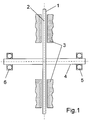
- the drive according to the invention on a bearing 5 and 6 mounted shaft 4, wherein the bearings 5 and 6 are received, for example, in a housing part.
- a circuit board 1, in particular multilayer printed circuit board, is rotatably connected to the shaft 4, wherein the normal direction of the printed circuit board plane is aligned parallel to the shaft axis of the shaft 4.
- stator cores 3 in Wellenachscardi axially in front of and behind the printed circuit board 1.
- the stator cores 3 have single-tooth windings, so that each tooth formed on the respective stator core 3 receives a separate winding.
- Each stator core 3 is pot-shaped and has at its edge of the pot circumferentially spaced apart, axially directed tooth projections with respective single tooth winding on.
- the tooth projections and thus the single tooth windings face each other axially, so that the magnetic field generated by a single tooth winding is for the most part introduced into an opposing tooth projection.
- the stator of an axial flux machine can be formed by the stator formed by means of the stator cores 3 and a rotating field can be generated which interacts with an active region of the printed circuit board 1.
- the single-tooth windings are interconnected as a rotating field winding and thus energized accordingly.
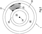
- the active region, that is active region 22, of the printed circuit board 1 is an annular subregion of the printed circuit board in which the winding lines 23 of the winding on the rotor side, run as conductor tracks of the printed circuit board, run radially.
- the annular portion is thus marked by a radial distance range of the circuit board.
- the main field generated by the teeth, ie tooth projections, the stator cores 3 penetrates the region axially covered by the printed circuit board 1.
- the teeth of the stator cores 3 thus cover those radial region which is radially covered by the active region of the printed circuit board 1.
- At a greater radial distance than the active region of the deflection region 21 is arranged, in particular radially outer deflection region, ie winding head region.
- At a smaller radial distance than the active region of the deflection region 26 is arranged, in particular radially inner deflection region, so winding head region.
- the tooth projections are not directly opposite to each other axially. You can also be rotated by half a tooth pitch against each other. Advantageously, then in principle results in twice the usable usable number. The field is then no longer directed purely axially. This is usable for a stator-side two-strand winding structure.
- the radial regions covered by the deflection regions 21 and 26 close radially directly to the radial region covered by the active region 22.
- a region 25 of the printed circuit board 1 equipped with components is arranged.
- an electronic circuit on the connected to the shaft 4 in the connection region 24 printed circuit board 1 can be arranged.
- a rotating field winding is arranged on the circuit board 1, wherein the rotating field winding is designed as a loop winding or wave winding.
- FIG. 3 the tracks of a first layer, ie a first layer
- FIG. 4 the traces of a second layer, so a second layer shows.
- the endpoints of the tracks in FIG. 3 and 4 are designed as plated-through holes, so that the interconnects of different layers, so layers, are electrically connected to each other.
- a grinding transfer is usable for supplying the rotating field winding arranged on the printed circuit board 1, the grinding transfer means 51 being shown for three phases.
- a power stage 52 in particular amplifier, with power semiconductor switches stationary, so rotatably connected to the stator core 3, arranged, wherein the power level of a control electronics 53 with pulse width modulated drive signals for the power semiconductor switch is driven and the multiphase output current of the power stage 52 is supplied to the grinding transmission means 51.
- a secondary winding 61 is rotatably connected to the shaft 4, wherein the arranged on the circuit board 1 electronic circuit is electrically powered via the inductive coupling.
- the inductively coupled to the secondary winding 61 primary winding 62 is rotatably connected to one of the stator cores 3.
- the primary winding 62 is fed by an inverter 63, which is controlled by an electronic control unit 64.
- a medium-frequency current can be imprinted, in particular with a frequency between 10 and 1000 kHz, preferably with a frequency between 100 and 200 kHz.
- the secondary winding 61 is a capacity in series and / or connected in parallel, so that the associated resonant frequency substantially corresponds to the impressed center frequency. In this way, evenly high efficiencies can be achieved despite fluctuations in the inductive coupling strength.
- a power actuator is provided on the circuit board 1 in the area 25.
- the electric power flow from the secondary winding 61 via the power actuator to the active region 22 of the circuit board 1 is controllable.
- an electronic control system is arranged, which has drive signals for the power actuator.
- the power actuator is designed as a power converter. Because of the spatial proximity to the active region 22, the power actuator is very low inductively connected to the active region 22.
- the inductance of the supply of electrical energy from the power actuator to the active region 22 is smaller than the inductance of the active region 22 together with deflection 21 and 26, so the rotor winding. In particular, it is less than one tenth of the inductance of the rotor winding.
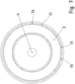
- each of the stator cores 3 has respective single-tooth windings 71. These are equally spaced in the circumferential direction and each arranged at the same radial distance. Each single tooth winding 71 is plugged onto a tooth-like projection of the stator core 3, which thus bundles the main field of the respective single-tooth winding 71 and leads out axially to the respective axially opposite tooth-like projection of the other stator core. 3
- the tooth coils are thus attached as a form of coils on the respective tooth-like projection.
- the stator cores 3 are designed as molded parts, in particular made of ferrite or a ferromagnetic material.
- the magnetic properties of the stator cores are isotropic.
- the material of the stator cores 3 SMC magnetic circuit materials are preferably used, so soft magnetic composite materials.
- stator steel For permanent magnet excitation on the stator steel is alternatively used.
- a rotating field winding is provided on the stator side and a rotary field winding in the active region 22 is likewise configured on the rotor side, there is thus a two-sidedly fed induction machine with an ironless rotor.
- the speed control range is twice as large compared to a single-ended induction machine when the frequency components are both equal and each corresponding to the supply frequency of the single-phase induction machine.
- the circuit board 1 has a circular edge. Thus, it is designed as a disc, in particular perforated disc, wherein the shaft 4 is performed in the centrally located hole.
- the printed circuit board 1 has an electrically insulating carrier material, with epoxy resin preferably being used for this purpose.
- Each of the layers, ie layers, has metallic Conductor tracks, for which purpose preferably copper or a copper-containing alloy is used.
- the rotor is ironless, so without laminated core.
- the carrier material has a specific magnetic permeability substantially comparable to that of air. Since the carrier material has only a small mass, the rotor has a very low moment of inertia overall.
- the plated-through holes are electrical connections of end points of the strip conductors which are spaced from one another in the normal direction of the printed circuit board.
- a borehole is introduced into the printed circuit board whose wall is metallized, that is coated with a metal layer.
- a respective copper profile is used as the conductor track, which is embedded in an electrically insulating base material.
- the copper profile of a stamped and bent part or of a continuous cast profile as stamped and bent part and the base material is epoxy resin.
- the copper profile has a thick cross-section, so that a high current carrying capacity can be achieved.
- a two-sided injectable induction machine such as the above-described electric machine 96, stator provided with a designed as a rotating field winding stator winding, which is powered by an inverter 94, which is arranged on the stator side, and has a laminated core.
- This inverter 94 has controllable power semiconductors, the drive signals of which are generated by control electronics having a regulator. The control of the controller works as U / f control.
- an ironless rotor winding designed as a rotating field winding is provided, which is fed by a further inverter 95, which is arranged on the rotor side.
- This inverter has controllable power semiconductors, whose drive signals are generated by an also arranged on the rotor control electronics having a regulator. In this case, this control arranged on the rotor side works as field-oriented control.
- the rotor-side control electronics together with inverter 95 is electrically powered or electrically powered by grinding transfer, as in the FIGS. 1 to 8 described.
- the supply of both inverters (94, 95) can be executed from a DC link capacitor 93, which can be fed via a rectifier 92 from an AC voltage source 91, in particular a supply network.
- u ⁇ s F u s d + j u s q (applies equally to all space pointers) the component-wise representation from which the control structure can be derived
- e d and e q are decoupling terms to decouple the system of equations and thus enable the simple regulation in the first place.
- the definition of the angle is in FIG. 16 illustrated.
- ⁇ ⁇ r - ⁇ s p .
- ⁇ the mechanical speed
- p the number of pole pairs
- ⁇ s or ⁇ r the stator-side or rotor-side electrical frequency.
- an improved stability in the regulation of the electric machine is achieved by two current regulators operating field-oriented on the rotor side and only one field-oriented magnetization current regulator (controller) on the stator side for i sd ) and a V / f control, which generates the voltage "u sq ", whereby a sensorless control concept is established on the stator side.
- the U / f control is based on the specification of speed-dependent frequency reference values ⁇ s, Soll .
- FIG. 15 is shown from the actual mechanical speed, which is either detected by means of a speed sensor or estimated by modeling in the controller, the frequency setpoint ⁇ s, Soll according to a characteristic which is stored in a look-up table, in particular by means of value pairs to be interpolated.
- This characteristic is in FIG. 12 shown enlarged, where the frequency setpoint ⁇ s, Soll is designated as frequency setpoint ⁇ s .
- the stator iron losses are avoided or at least reduced in this frequency range.
- the synchronous speed ⁇ 0 in the case of the electric machine that can be fed in on two sides is twice as high as the synchronous speed in the case of an electric machine that can be fed in only on one side.
- the frequency setpoint ⁇ s, target is determined by means of the characteristic. As in FIG. 15 is shown, with the ⁇ sd, is multiplied, ie with that component of the actual value of the Statorhneraumze which this has in the direction of the magnetization-forming current component. The component ⁇ sd, thus causes the magnetization.
- a controller with integrating portion is provided here, as a controller, a linear controller, such as PI controller is used.
- a stator voltage space pointer is formed which is provided in the direction of the field orientation angle increased by ⁇ .
- Such a space vector U sU , U sV , U sW ) is then fed to the stator-side field winding, ie the stator winding.
- the rotor frequency is impressed via a direct U / f control, in particular on the voltage component u rq .
- the stator frequency is impressed by the voltage component u sq , as in FIG. 15 shown.
- the rotor frequency results from the fact that the speed controller mechanical Keeps the speed constant and thus sets the necessary rotor frequency according to the speed.
- the difference between the setpoint for the mechanical speed ⁇ and the detected or estimated actual value ⁇ is supplied to the mechanical speed of a controller member, in particular a linear controller element, such as P-controller, PI controller or PID controller.
- a controller member in particular a linear controller element, such as P-controller, PI controller or PID controller.
- Manipulated variable of this regulator member is the desired value i rq, target for the rotor-side torque-generating current component.
- the deviation from the corresponding actual value i rq is supplied to an integrator whose output signal is summed up on the decoupling term e q .
- the setpoint i rd, setpoint for the magnetization-forming current component is set to zero and the deviation from the corresponding actual value is fed to an integrator whose output signal is summed up on the decoupling term e d .
- a controller with integrating portion is also provided here, with a linear controller, such as PI controller, is used as a controller.
- the current component i ra and i rb of the detected current space vector are multiplied by the ohmic resistance of the rotor winding R R, and the difference to the respective current component U ra and U rb is formed.
- the products thus formed are supplied to a respective integrator and the two output signals of the integrators as a complex size, in particular as a two-dimensional space vector represented.
- the complex quantity is multiplied by L S / L h and added to the result value of the current-space vector (i ra + j * i rb ), which is also complex and multiplied by (L h -L S * L r / L h ). That way is Thus, the stator flux determined, ie the field orientation angle ⁇ s and the magnetization forming portion of the magnetic flow space vector.
- a particular advantage of the invention is that the field orientation angle necessary for the control, that is to say the position of the field, can be determined with a rather simple mathematical model. This provision can be carried out in the invention for even small mechanical speeds and even to a standstill, since the electrical frequency, in particular rotor frequency, never falls below a minimum value. By way of example, this minimum value is between 5 Hz and 15 Hz, in particular between 10 Hz and 12 Hz. It is particularly advantageous that the so-called voltage model shown in the figures can be used for the calculation of the field orientation angle.
- the control structure according to the invention has three current regulators and an additional U / f control.
- the magnetization state is determined here by the current component i sd , as in FIG FIG. 15 shown.
- the torque is determined by the current component i rq , as in FIG. 14 shown.
- the characteristic curve used according to the invention makes it possible to determine the voltage u sq to be set from the measured or estimated mechanical rotational speed and to predetermine the machine, as in FIG FIG. 15 shown.
- the abscissa in each case the mechanical speed related to the synchronous speed ⁇ 0 applied to a one-sided fed machine.
- the basic setting range for machines fed on two sides is up to twice the synchronous speed of a single-sided machine.
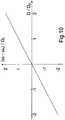
- FIG. 10 the mechanical speed is shown as the difference of the frequencies above the speed related to the synchronous speed.
- an angle bisector is provided here. This illustration is for illustrative purposes in the Figures 11 and 12 following graph. Because the difference of the two graphs gives the course in FIG. 10 ,
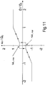
- FIG. 11 the rotor frequency resulting from the stator frequency control is plotted according to the method proposed here.
- FIG. 12 Accordingly, the speed-dependent Statorstellfrequenz is plotted.
- the characteristics presented here provide for a reduction of the stator supply frequency to 0 Hz over a wide speed range, namely the range between ⁇ min / ⁇ 0 and 1, as in FIG. 12 is shown. In this area, no iron losses occur in the stator and the machine is operated similarly to a DC-excited synchronous machine.
- the EMF ie the electromotive force
- the EMF is so low that a determination of the rotor angle position based thereon is no longer useful and therefore an angle sensor or an other mathematical calculation or estimation method, which does not depend on the determination, has to be used the EMK is instructed.
- the potential of the control method according to the invention is on the one hand in the ability to make two-sided fed induction machines down to the lowest speeds and even at standstill controllable. On the other hand, a minimization of the rotor current can be achieved. In addition, an improvement in the performance of transmission systems and the efficiency of the drive can be achieved. Furthermore, the method according to the invention, in particular the lowering of the stator frequency to 0 Hz, is particularly advantageous in machines with an ironless rotor. The efficiency is significantly improved. Because in this area no iron losses occur in the entire machine, because the frequency acted rotor is ironless and the stator is not subjected to frequency.
- the invention instead of on a rotary electric machine, in another embodiment of the invention, the invention also in a linear motor in an analogous manner executable.
- FIG. 7 and 8th also wave or loop windings executed.
Landscapes
- Engineering & Computer Science (AREA)
- Power Engineering (AREA)
- Windings For Motors And Generators (AREA)
- Control Of Ac Motors In General (AREA)
Description
Die Erfindung betrifft ein Verfahren zum Betreiben einer Elektromaschine und einen Elektromotor.The invention relates to a method for operating an electric machine and an electric motor.
Es ist allgemein bekannt, dass ein Gleichstrommotor einen mechanisch betriebenen Kommutator benötigt. Der Rotor weist eine Wicklung auf.It is well known that a DC motor requires a mechanically operated commutator. The rotor has a winding.
Bei Synchronmotoren ist bekannt, auf dem Rotor Dauermagnete vorzusehen, die üblicherweise einen magnetischen Rückschluss aufweisen, also zur Schaffung des Rückschlusses ein Blechpaket am Rotor vorgesehen ist. Der Rotor ist somit nicht eisenlos.In synchronous motors is known to provide permanent magnets on the rotor, which usually have a magnetic return, so is provided to create the conclusion of a laminated core on the rotor. The rotor is thus not iron-free.
Aus der VeröffentlichungFrom the publication
ist bekannt, bei einer zweiseitig eingespeisten und zweiseitig eisenbehafteten Elektromaschine rotorseitig eine U/f-Steuerung vorzusehen und statorseitig eine feldorientierte Regelung. Dabei wird auf die gewünschte mechanische Drehzahl Ω hingeregelt, während die elektrischen Frequenzen, also die elektrischen Drehfrequenzen des rotorseitigen und statorseitigen Drehfeldes eine Minimalfrequenz nicht unterschreiten. Hierzu wird eine hysteresebehaftete Kennlinie verwendet, die jedoch Eisenverluste zur Folge hat. It is known to provide a U / f control on the rotor side in the case of a double-sidedly fed and two-sided iron-coated electric machine, and a field-oriented control on the stator side. In this case, the desired mechanical rotational speed Ω is controlled while the electrical frequencies, that is to say the electrical rotational frequencies of the rotor-side and stator-side rotating field, do not fall below a minimum frequency. For this purpose, a hysteresis characteristic is used, which however results in iron losses.
Aus der
Aus der Veröffentlichung "
Aus der
Aus der
Aus der
Aus der
Aus der
Der Erfindung liegt daher die Aufgabe zugrunde, einen Elektromotor weiterzubilden, insbesondere mit hohem Wirkungsgrad.The invention is therefore based on the object of developing an electric motor, in particular with high efficiency.
Erfindungsgemäß wird die Aufgabe bei den Verfahren nach den in Anspruch 1 und 2 und bei dem Elektromotor nach den in Anspruch 11 angegebenen Merkmalen gelöst. Wichtige Merkmale bei dem Verfahren zum Betreiben einer Elektromaschine, welche einen gegenüber einem Stator relativ bewegbaren Läufer, insbesondere Rotor, aufweist, sind, dass die mechanische, zum Stator relative Geschwindigkeit des Läufers, insbesondere Drehgeschwindigkeit des Rotors, erfasst oder geschätzt wird, insbesondere von einer Steuerelektronik,
wobei am Läufer eine Wicklung, insbesondere Rotorwicklung, angeordnet ist, die als Drehfeldwicklung ausgeführt ist,
wobei am Stator eine Statorwicklung angeordnet ist, die ebenfalls als Drehfeldwicklung ausgeführt ist,
wobei jede Drehfeldwicklung von einem jeweiligen Wechselrichter gespeist wird, insbesondere also die läufer- oder rotorseitige Drehfeldwicklung von einem läufer- oder rotorseitigen Wechselrichter und die statorseitige Drehfeldwicklung von einem statorseitigen Wechselrichter,
wobei aus der mechanischen Geschwindigkeit gemäß einer Kennlinie eine elektrische Frequenz ωS,Soll der vom statorseitigen Wechselrichter an die Statorwicklung gespeisten Spannung, insbesondere die elektrische Frequenz des statorseitig erzeugten Drehfeldes, insbesondere also die Statorspeisefrequenz, bestimmt wird,
insbesondere wobei die Kennlinie einen hysteresebehaftete Abhängigkeit der elektrischen Frequenz ωS,Soll von der mechanischen Geschwindigkeit darstellt,
wobei die Kennlinie derartig ausgeführt ist, dass die Statorspeisefrequenz auf weniger als eine Minimalfrequenz, insbesondere auf Null Hertz, abgesenkt ist in einem Drehzahlbereich zumindest von Ωmin bis Ω0,
wobei Ωmin eine erste Drehzahl ist und
wobei Ω0 eine zweite Drehzahl ist, wobei der Betrag der zweiten Drehzahl Ω0 größer ist als der Betrag der ersten Drehzahl,
insbesondere wobei der von der Hysterese überdeckte Drehzahlbereich betragsmäßig kleiner ist als der Betrag der ersten Drehzahl Ωmin .According to the invention the object is achieved in the method according to
wherein on the rotor a winding, in particular rotor winding, is arranged, which is designed as a rotating field winding,
wherein a stator winding is arranged on the stator, which is also designed as a rotating field winding,
wherein each rotating field winding is fed by a respective inverter, in particular thus the rotor or rotor-side rotating field winding of a rotor or rotor-side inverter and the stator-side rotating field winding of a stator-side inverter,
wherein an electrical frequency ω S, set point of the voltage fed from the stator-side inverter to the stator winding, in particular the electrical frequency of the stator-generated rotating field, in particular the stator supply frequency , is determined from the mechanical velocity in accordance with a characteristic curve,
in particular wherein the characteristic curve represents a hysteresis-dependent dependence of the electrical frequency ω S, desired value of the mechanical speed,
wherein the characteristic curve is embodied such that the stator supply frequency is reduced to less than a minimum frequency, in particular to zero Hertz, in a rotational speed range at least from Ω min to Ω 0 ,
where Ω min is a first speed and
where Ω 0 is a second speed, wherein the amount of the second speed Ω 0 is greater than the amount of the first speed,
in particular wherein the speed range covered by the hysteresis is smaller than the amount of the first rotational speed Ω min .
Von Vorteil ist dabei, dass durch die Absenkung Verlustleistungen verringert werden, insbesondere Eisenverluste. Weiterer Vorteil ist, dass kleine mechanische Drehzahlen oder sogar bei Stillstand der Rotorwelle die Rotorspeisefrequenz und Statorspeisefrequenz nicht verschwinden sondern über einem Minimalwert bleiben. Denn die mechanische Drehzahl wird durch die Differenz der rotorseitigen und statorseitigen Speisefrequenzen bestimmt. Somit ist eine kleine Differenz auch mit großen Speisefrequenzen erreichbar. Hieraus ergibt sich der Vorteil, dass offene, also nicht rückgekoppelte Integrationen in einer Regelung verwendbar sind, ohne dass ein Divergieren stattfindet.The advantage here is that the reduction reduces power losses, especially iron losses. Another advantage is that small mechanical speeds or even at standstill of the rotor shaft, the rotor feed frequency and Statorpeisefrequenz not disappear but remain above a minimum value. Because the mechanical speed is determined by the difference of the rotor-side and stator-side supply frequencies. Thus, a small difference can be achieved even with large supply frequencies. From this results The advantage that open, so not feedback integrations can be used in a scheme without diverging takes place.
Bei einer vorteilhaften Ausgestaltung werden jeweils Halbleiterschaltern des jeweiligen Wechselrichters von einer Steuerelektronik Ansteuersignale zugeführt, wobei die jeweilige Steuerelektronik eine Regelvorrichtung aufweist. Von Vorteil ist dabei, dass rotorseitig und statorseitig jeweils ein Wechselrichter mit zugehöriger Steuerelektronik angeordnet ist. Auf diese Weise ist eine gute Regelbarkeit der Elektromaschine erreichbar und außerdem ein größerer Stellbereich und eine größere Dynamik bei der Regelung.In an advantageous embodiment, respective semiconductor switches of the respective inverter supplied by a control electronics drive signals, wherein the respective control electronics has a control device. The advantage here is that the rotor side and the stator side, an inverter is arranged with associated control electronics. In this way, a good controllability of the electric machine can be achieved and also a larger adjustment range and greater dynamics in the scheme.
Bei einer vorteilhaften Ausgestaltung weist die statorseitige Regelvorrichtung eine U/f-Steuerung auf. Von Vorteil ist dabei, dass ein sensorloses und somit einfaches Reglerkonzept ermöglicht ist.In an advantageous embodiment, the stator-side control device on a U / f control. The advantage here is that a sensorless and thus simple controller concept is possible.
Bei einer vorteilhaften Ausgestaltung weist die läuferseitige oder rotorseitige Regelvorrichtung eine feldorientierte Regelung auf. Von Vorteil ist dabei, dass eine feldorientierte Regelung einfach aufbaubar ist, insbesondere ohne rückgekoppelte Integrierglieder, und trotzdem bei kleinen Drehzahlen anwendbar ist. Denn im Stand der Technik sind bei feldorientierten Regelungen für niedrige Drehzahlen und somit Speisefrequenzen bis zum Quasi-Stillstand besondere aufwendige Zusatzmaßnahmen in der Regelung notwendig. Bei der Erfindung hingegen sind diese Maßnahmen verzichtbar, da die Speisefrequenzen oberhalb kritischer Minimalwerte bleiben.In an advantageous embodiment, the rotor-side or rotor-side control device has a field-oriented control. The advantage here is that a field-oriented control is easy to assemble, in particular without feedback integrators, and is still applicable at low speeds. Because in the prior art special complex additional measures in the scheme are necessary for field-oriented controls for low speeds and thus supply frequencies to quasi-standstill. By contrast, in the case of the invention, these measures can be dispensed with since the supply frequencies remain above critical minimum values.
Bei einer vorteilhaften Ausgestaltung ist die Minimalfrequenz der Statorspeisefrequenz 0 Hz. Von Vorteil ist dabei, dass die Eisenverluste im Stator verminderbar oder sogar gänzlich verhinderbar sind.In an advantageous embodiment, the minimum frequency of the
Bei einer vorteilhaften Ausgestaltung ist die erste Drehzahl Ωmin derart gewählt, dass offene und/oder nicht rückgekoppelte Integrationen der feldorientierten, insbesondere zeitdiskret ausgeführten, insbesondere numerisch arbeitenden, Regelung nicht divergieren. Von Vorteil ist dabei, dass durch die Vermeidung von niedrigen rotorseitigen und statorseitigen Speisefrequenzen unterhalb der ersten Drehzahl nicht rückgekoppelte Integrationen verwendbar sind. Rundungsfehler, die bei insbesondere bei zeitdiskreten Reglerstrukturen auftreten, führen somit zu keiner wesentlichen Abweichung bei der Rotorlagebestimmung. In an advantageous embodiment, the first speed Ω min is selected such that open and / or non-feedback integrations of the field-oriented, in particular time-discretely executed, in particular numerically operating, control do not diverge. The advantage here is that non-feedback integrations can be used by avoiding low rotor-side and stator-side supply frequencies below the first speed. Rounding errors, especially in time-discrete Controller structures occur, thus leading to no significant deviation in the rotor position determination.
Bei einer vorteilhaften Ausgestaltung ist die erste Drehzahl Ωmin derart gewählt, dass die gemäß Kennlinie und Regelung sich einstellende elektrische rotorseitige Speisefrequenz ωr, min einen Minimalwert nicht unterschreitet, insbesondere wobei der Minimalwert zwischen 1 Hz und 20 Hz beträgt, insbesondere zwischen 10 Hz und 15 Hz. Von Vorteil ist dabei, dass die feldorientierte Regelung mit einem recht einfachen Maschinenmodell ausführbar ist, also kein großer Aufwand an mathematischer Modellierung notwendig ist.In an advantageous embodiment, the first speed Ω min is selected such that the electrical rotor-side feed frequency ω r, min does not fall below a minimum value, in particular wherein the minimum value is between 1 Hz and 20 Hz, in particular between 10 Hz and 15 Hz. The advantage here is that the field-oriented control is feasible with a fairly simple machine model, so no great amount of mathematical modeling is necessary.
Bei einer vorteilhaften Ausgestaltung ist die zweite Drehzahl Ω0 die synchrone Drehzahl einer einseitig gespeisten Elektromaschine oder die zweite Drehzahl Ω0 gleicht der Hälfte der synchronen Drehzahl der zweiseitig gespeisten Elektromaschine, wenn die Stator- und Rotorfrequenzen gleich groß sind und jeweils der einer einseitig gespeisten Drehfeldmaschine entsprechen. Von Vorteil ist dabei, dass über einen weiten Drehzahlbereich Eisenverluste verringerbar sind.In an advantageous embodiment, the second speed Ω 0 is the synchronous speed of a single-side electric machine or the second speed Ω 0 equal to half the synchronous speed of the two-sided electric machine when the stator and rotor frequencies are equal and each of a one-sided induction machine correspond. The advantage here is that over a wide speed range iron losses can be reduced.
Bei einer vorteilhaften Ausgestaltung wird als rotorseitig vorgegebener Sollwert für den magnetisierungsbildenden Stromanteil Null vorgegeben, insbesondere zur Reduktion von Verlustleistung. Von Vorteil ist dabei, dass eine eisenlose Wicklung rotorseitig verwendbar ist und somit keine Magnetisierung rotorseitig erzeugt werden muss. Somit sind auch rotorseitige Eisenverluste vermieden.In an advantageous embodiment, set as the rotor side preset value for the magnetizing current component zero, in particular for the reduction of power loss. The advantage here is that an ironless winding is used on the rotor side and thus no magnetization must be generated on the rotor side. Thus, rotor-side iron losses are avoided.
Bei einer vorteilhaften Ausgestaltung wird die U/f-Steuerung die Abweichung der mechanischen erfassten oder geschätzten Drehzahl zum vorgegebenen Drehzahl-Sollwert einem Reglerglied zugeführt, das als Ausgangssignal den Sollwert des rotorseitigen momentbildenden Stromanteils erzeugt,
wobei die Abweichung zwischen diesem Sollwert und dem Istwert des momentbildenden rotorseitigen Stromanteils eine Reglerglied, insbesondere Integrierglied, zugeführt wird, aus dessen Ausgangssignal ein Spannungswert, insbesondere die Komponente des Spannungsraumzeigers in Richtung des momentbildenden Stromanteils, bestimmt wird,
insbesondere unter Aufsummation des eq-Signals. Von Vorteil ist dabei, dass der zu stellende Spannungsraumzeiger, welcher am rotorseitigen Wechselrichter ausgangsseitig bereit gestellt wird zur Speisung der rotorseitigen Wicklung, in einfacher Weise aus den erfassten Werten bestimmbar ist, insbesondere aus der erfassten Drehzahl und dem erfassten Strom.In an advantageous embodiment, the U / f control, the deviation of the mechanical detected or estimated speed is supplied to the predetermined speed setpoint a controller member which generates the setpoint value of the rotor-side torque-generating current component as an output signal,
the deviation between this desired value and the actual value of the moment-forming rotor-side current component being supplied to a regulator element, in particular integrating element, from the output signal of which a voltage value, in particular the component of the voltage space vector in the direction of the moment-forming current component, is determined;
particular summation of the signal e q. The advantage here is that the voltage space pointer to be provided, which is provided on the output side of the rotor-side inverter for feeding the rotor-side winding, can be determined in a simple manner from the detected values, in particular from the detected rotational speed and the detected current.
Bei einer vorteilhaften Ausgestaltung weist die rotorseitig angeordnete feldorientierte Regelung Integrierglieder auf, aus deren Ausgangssignalen der Feldorientierungswinkel bestimmt wird,
insbesondere unter Aufsummation eines Anteils des Stromraumzeigers auf den durch die Ausgangssignale dargestellten Raumzeiger. Von Vorteil ist dabei, dass keine Rückkopplung der Integrierglieder notwendig ist, da die Speisefrequenzen stets hoch genug sind, so dass ein Divergieren der Integrationsergebnisse vermeidbar sind.In an advantageous embodiment, the field-oriented control arranged on the rotor side has integrators, from whose output signals the field orientation angle is determined,
in particular with the summation of a portion of the current space pointer on the space vector represented by the output signals. The advantage here is that no feedback of the integrators is necessary because the supply frequencies are always high enough so that a divergence of the integration results are avoidable.
Wichtige Merkmale der Erfindung bei dem Elektromotor sind, dass er einen Stator und einen relativ zum Stator drehbar angeordneten Rotor aufweist,
wobei der Rotor einen Aktivbereich aufweist, insbesondere zur Drehmomenterzeugung bei Wechselwirkung des Aktivbereichs mit dem vom Stator erzeugten Magnetfeld,
wobei der Aktivbereich elektrisch bestrombare Leiterbahnen einer Multilayer-Leiterplatte, insbesondere also einer mehrlagigen Leiterplatte, aufweist.Important features of the invention in the electric motor are that it has a stator and a rotor rotatably mounted relative to the stator,
wherein the rotor has an active region, in particular for torque generation upon interaction of the active region with the magnetic field generated by the stator,
wherein the active region has electrically energizable conductor tracks of a multilayer printed circuit board, in particular of a multilayer printed circuit board.
Von Vorteil ist dabei, dass ein eisenloser Scheibenläufermotor als Drehfeldmaschine ausführbar ist, wobei eine mehrsträngige Rotorwicklung des erfindungsgemäßen Elektromotors als Drehstromwicklung in Form einer eisenlosen Luftspaltwicklung ausführbar ist, die als Leiterbahnen einer Leiterplatte ausführbar ist. Somit muss bei der Herstellung keine Wicklung gewickelt werden sondern nur eine Leiterplatte mit entsprechenden Leiterbahnen versehen werden. Die aufwendige Herstellung von gewickelten Rotoren entfällt somit. Durch den mehrlagigen Aufbau der Leiterplatte ist auch ein komplexes Wicklungsschema in einfacher Weise realisierbar. Ein mechanischer Kommutator ist verzichtbar. Der Stator ist entweder mittels Dauermagneten permanenterregt oder er weist eine Statorwicklung auf, so dass er elektrisch erregbar ist.The advantage here is that an ironless pancake motor is designed as a rotating field machine, wherein a multi-stranded rotor winding of the electric motor according to the invention as a three-phase winding in the form of an ironless air gap winding is executable, which is executable as printed conductors of a printed circuit board. Thus, no winding must be wound in the production but only a circuit board to be provided with appropriate tracks. The complex production of wound rotors is thus eliminated. Due to the multilayer structure of the circuit board and a complex winding scheme is feasible in a simple manner. A mechanical commutator is dispensable. The stator is permanently excited either by means of permanent magnets or it has a stator winding, so that it is electrically excitable.
Durch die erfindungsgemäße eisenlose Luftspaltwicklung existieren außerdem keine magnetischen Vorzugsstellungen über dem Verdrehwinkel des Rotors relativ zum Stator. Insbesondere rastet der Rotor nicht, wie bei gewöhnlichen Synchronmaschinen. Daher ist ein sehr gleichförmiger Rundlauf erreichbar. Außerdem sind Eisenverluste im Rotor der Maschine vermeidbar.Moreover, due to the ironless air gap winding according to the invention, there are no preferred magnetic positions over the angle of rotation of the rotor relative to the stator. In particular, the rotor does not snap, as in ordinary synchronous machines. Therefore, a very uniform concentricity can be achieved. In addition, iron losses in the rotor of the machine can be avoided.
Bei einer vorteilhaften Ausgestaltung ist die Leiterplatte drehfest mit dem Rotor verbunden,
insbesondere wobei die Leiterplatte drehfest mit einem Wellenabschnitt des Rotors verbunden ist,
insbesondere wobei der Rotor über Lager gelagert ist, die in einem Teil, insbesondere Gehäuseteil, aufgenommen sind, welches fest mit dem Stator, insbesondere den Statorkernen, verbunden sind. Von Vorteil ist dabei, dass zur Herstellung des Rotors nur eine Leiterplatte herzustellen ist, die mit dem Rotor verbunden ist, insbesondere bei der Fertigung beispielsweise aufgesteckt wird.In an advantageous embodiment, the circuit board is rotatably connected to the rotor,
in particular wherein the printed circuit board is non-rotatably connected to a shaft section of the rotor,
in particular wherein the rotor is mounted via bearings, which are received in a part, in particular housing part, which are fixedly connected to the stator, in particular the stator cores. The advantage here is that for the production of the rotor, only a circuit board is to be produced, which is connected to the rotor, in particular, for example, in the production is plugged.
Bei einer vorteilhaften Ausgestaltung bilden die Leiterbahnen der Multilayer-Leiterplatte eine Drehfeldwicklung. Von Vorteil ist dabei, dass das Layout der Leiterplatte derart ausführbar ist, dass eine Drehfeldwicklung realisierbar ist.In an advantageous embodiment, the tracks of the multilayer printed circuit board form a rotating field winding. The advantage here is that the layout of the circuit board is executable such that a rotating field winding can be realized.
Bei einer vorteilhaften Ausgestaltung weist der Stator Dauermagnete auf, insbesondere deren Magnetisierungsrichtung jeweils parallel zur Drehachse des Rotors ausgerichtet sind, insbesondere axial ausgerichtet sind. Von Vorteil ist dabei, dass der Stator ohne großen Aufwand herstellbar und betreibbar ist. Insbesondere ist keine Bestromung des Stators notwendig, da die Dauermagnete ein axial gerichtetes Magnetfeld erzeugen.In an advantageous embodiment, the stator to permanent magnets, in particular whose magnetization direction are aligned parallel to the axis of rotation of the rotor, in particular axially aligned. The advantage here is that the stator can be produced and operated without much effort. In particular, no energization of the stator is necessary because the permanent magnets generate an axially directed magnetic field.
Bei einer vorteilhaften Ausgestaltung weist der Stator eine Statorwicklung auf zur Erzeugung eines Drehfeldes, insbesondere wobei die Statorwicklung eine Drehfeldwicklung ist. Von Vorteil ist dabei, dass durch die geeignete Bestromung der Statorwicklung mit einem Wechselstrom, insbesondere mit einem mehrphasigen Wechselstrom, ein Drehfeld erzeugbar ist.In an advantageous embodiment, the stator has a stator winding for generating a rotating field, in particular wherein the stator winding is a rotating field winding. The advantage here is that by the appropriate energization of the stator winding with a AC, in particular with a multi-phase alternating current, a rotating field is generated.
Bei einer vorteilhaften Ausgestaltung verlaufen die im Aktivbereich angeordneten Leiterbahnen radial und/oder erstrecken sich radial. Von Vorteil ist dabei, dass das vom Stator erzeugte Magnetfeld axial gerichtet sein darf, um einen hohen Wirkungsgrad bei der Drehmomenterzeugung erreichbar zu machen.In an advantageous embodiment, the conductor tracks arranged in the active area extend radially and / or extend radially. The advantage here is that the magnetic field generated by the stator may be axially directed to make a high efficiency in the torque generation achievable.
Bei einer vorteilhaften Ausgestaltung schließt sich an den Aktivbereich radial innen und radial außen jeweils ein Umlenkbereich an,
insbesondere wobei die Leiterbahnen einer jeweiligen Lage in einem Umlenkbereich jeweils enden in einer axial gerichteten Durchkontaktierung, insbesondere axial gerichteten durchkontaktierten Bohrung der Leiterplatte, insbesondere zur elektrischen Verbindung von Leiterbahnen verschiedener Lagen. Von Vorteil ist dabei, dass die Durchkontaktierungen und der Umlenkbereich radial außerhalb oder innerhalb, also radial angrenzend oder beabstandet, von dem Hauptfeld des von der Statorwicklung erzeugten Magnetfeldes angeordnet sind.In an advantageous embodiment, a deflection region adjoins the active region radially inward and radially outward,
in particular wherein the conductor tracks of a respective layer in a deflection region respectively terminate in an axially directed through-connection, in particular axially directed plated-through bore of the printed circuit board, in particular for electrical connection of conductor tracks of different layers. The advantage here is that the vias and the deflection are arranged radially outside or inside, ie radially adjacent or spaced from the main field of the magnetic field generated by the stator winding.
Es ist außerdem möglich auf die Durchkontaktierungen zu verzichten, falls pro Lage nur ein Strang ausgeführt wird.It is also possible to dispense with the vias, if only one strand per layer is performed.
Bei einer vorteilhaften Ausgestaltung weist der Stator einen oder zwei sich axial gegenüber stehende Statorkerne auf. Von Vorteil ist dabei, dass ein geringes Streufeld erreichbar ist, indem die zahnartigen Vorsprünge aufeinander zu ausgerichtet angeordnet sind, also ein möglichst geringer Luftspalt zwischen den jeweils sich gegenüberstehenden zahnartigen Vorsprüngen vorhanden ist.In an advantageous embodiment, the stator has one or two axially opposed stator cores. The advantage here is that a low stray field can be achieved by the tooth-like projections are arranged aligned with each other, so the smallest possible air gap between the respective opposing tooth-like projections is present.
Bei einer vorteilhaften Ausgestaltung sind am Statorkern zahnartige Vorsprünge ausgebildet, die in Umfangsrichtung voneinander regelmäßig beabstandet sind, insbesondere und auf gleichem Radialabstand angeordnet sind,
wobei die Statorwicklung Einzelwicklungen aufweist, insbesondere aus Einzelwicklungen gebildet ist,
wobei jede Einzelwicklung auf einem jeweiligen zahnartigen Vorsprung aufgesteckt angeordnet ist,
insbesondere wobei das aus den Einzelwicklungen erzeugte Magnetfeld im Wesentlichen axial gerichtet ist,
insbesondere wobei das aus den Einzelwicklungen erzeugte Hauptfeld des Magnetfelds axial gerichtet ist. Von Vorteil ist dabei, dass eine Statorwicklung in einfacher Weise aus aufgesteckten Einzelzahnwicklungen zusammensetzbar ist. Somit sind einander sich gleichende Einzelzahnwicklungen aus einem Lager verwendbar.In an advantageous embodiment, tooth-like projections are formed on the stator core, which are regularly spaced from one another in the circumferential direction, in particular, and are arranged at the same radial distance,
the stator winding having individual windings, in particular being formed from individual windings,
wherein each individual winding is mounted plugged on a respective tooth-like projection,
in particular, wherein the magnetic field generated from the individual windings is directed substantially axially,
in particular, wherein the main field of the magnetic field generated from the individual windings is axially directed. The advantage here is that a stator winding can be assembled in a simple manner from plugged single-tooth windings. Thus, mutually equivalent single-tooth windings can be used from a warehouse.
Wenn die Statorhälften verdreht sind ist das Feld nicht rein axial gerichtet und der wirksame Luftspalt wird größer, sowie die Streuung. Dafür ergibt sich der Vorteil der doppelten Nutzzahl.When the stator halves are twisted, the field is not purely axially directed and the effective air gap becomes larger, as well as the scattering. This results in the advantage of twice the payload.
Alternativ zu den Einzelwicklungen ist auch eine Schleifenwicklung oder Wellenwicklung ausführbar.As an alternative to the individual windings, a loop winding or wave winding can also be executed.
Bei einer vorteilhaften Ausgestaltung ist der jeweilige Statorkern topfartig ausgeformt, wobei die zahnartigen Vorsprünge am Topfrand angeordnet sind,
insbesondere wobei der Statorkern jeweils aus SMC Material gefertigt ist. Von Vorteil ist dabei, dass das Magnetfeld, insbesondere der Hauptfeldanteil, geschlossen in zwei sich axial gegenüberstehenden, zueinander spiegelsymmetrisch zu einer zwischen den beiden Statorkernen angeordneten Ebene angeordneten Statorkerne führbar ist mit Ausnahme des Luftspalts zwischen den beiden Statorkernen.In an advantageous embodiment of the respective stator core is pot-shaped, wherein the tooth-like projections are arranged on the pot edge,
in particular wherein the stator core is made of SMC material. It is advantageous in this case that the magnetic field, in particular the main field component, can be guided closed in two axially opposed stator mirrors arranged mirror-symmetrically to one another between the two stator cores, with the exception of the air gap between the two stator cores.
Bei Dauermagneterregung ist die Ausführung des Stators auch aus Eisen oder Stahl möglich. SMC wird nur bei elektrischer Erregung verwendet, da sich die Richtung des magnetischen Flusses ändert und in massivem Stahl sehr große Wirbelströme, also auch Verluste, auftreten würden.In the case of permanent magnet excitation, the stator can also be made of iron or steel. SMC is only used in electrical excitation, as the direction of the magnetic flux changes and in massive steel very large eddy currents, including losses, would occur.
Bei einer vorteilhaften Ausgestaltung weist die Leiterplatte einen kreisförmigen radialen Außenrand auf. Von Vorteil ist dabei, dass keine Unwucht von der Leiterplatte verursacht wird.In an advantageous embodiment, the circuit board has a circular radial outer edge. The advantage here is that no imbalance is caused by the circuit board.
Bei einer vorteilhaften Ausgestaltung sind die Leiterbahnen aus Kupfer oder einem Kupferhaltigem Werkstoff und/oder sind die Leiterbahnen der inneren Lagen der Leiterplatte in einem elektrisch isolierenden Trägermaterial eingebettet, insbesondere wobei das Trägermaterial zumindest Epoxidharz aufweist. Von Vorteil ist dabei, dass eine einfache Fertigung, insbesondere auch eine Massenfertigung, ausführbar ist.In an advantageous embodiment, the conductor tracks made of copper or a copper-containing material and / or the tracks of the inner layers of the circuit board are embedded in an electrically insulating carrier material, in particular wherein the carrier material comprises at least epoxy resin. The advantage here is that a simple production, especially a mass production, is executable.
Bei einer vorteilhaften Ausgestaltung ist die Leiterplatte mit elektronischen Bauteilen einer elektronischen Schaltung bestückt, insbesondere auf kleinerem Radialabstand als der Aktivbereich und/oder als die Umlenkbereiche angeordnet sind. Von Vorteil ist dabei, dass das Drehmoment auf einem größeren Radialabstand erzeugbar ist als die elektronische Schaltung angeordnet ist. Somit ist auch die durch die elektronische Schaltung bewirkte Erhöhung des Trägheitsmoments gering. Vorteilhafterweise ist die Bestückung der Leiterplatte automatisiert ausführbar und somit mit geringem Kostenaufwand eine Leistungsstellende Anordnung auf dem drehenden Teil, also Rotor, anordenbar.In an advantageous embodiment, the circuit board is equipped with electronic components of an electronic circuit, in particular at a smaller radial distance than the active area and / or are arranged as the deflection. The advantage here is that the torque can be generated at a greater radial distance than the electronic circuit is arranged. Thus, the increase of the moment of inertia caused by the electronic circuit is also small. Advantageously, the assembly of the circuit board is automated executable and thus at low cost a Leistungsstellende arrangement on the rotating part, so rotor, can be arranged.
Bei einer vorteilhaften Ausgestaltung ist der Aktivbereich, die Rotorwicklung und/oder die elektronische Schaltung elektrische Leistung über eine induktive Kopplung zuführbar,
insbesondere wobei der Rotor mit einer Sekundärwicklung verbunden ist, die induktiv an eine mit dem Stator verbundene, insbesondere drehfest verbundene, Primärwicklung gekoppelt ist, insbesondere wobei die Sekundärwicklung axial beabstandet ist von der Leiterplatte,
insbesondere wobei Sekundärwicklung und Primärwicklung als Ringwicklungen ausgeführt sind, insbesondere deren Wickelachse parallel zur Rotorachse ausgerichtet ist,
insbesondere wobei in die Primärwicklung von einer elektrischen Einspeisung ein mittelfrequenter Strom eingeprägt wird,
insbesondere wobei die Einspeisung einen Gyrator aufweist, insbesondere wobei der Gyrator als Vierpol ausgeführt ist und zumindest eine derartige Kapazität und mindestens eine derartige Induktivität aufweist, dass die zugehörige Resonanzfrequenz der eingeprägten Mittelfrequenz im Wesentlichen gleicht,
insbesondere wobei der Sekundärwicklung eine Kapazität in Reihe oder parallel zugeschaltet ist, so dass die zugehörige Resonanzfrequenz im Wesentlichen der Mittelfrequenz entspricht. Von Vorteil ist dabei, dass auch bei Schwankungen der induktiven Kopplung ein im Wesentlichen unverändert hoher Wirkungsgrad bei der induktiven Energieübertragung von der Primärwicklung an die Sekundärwicklung erreichbar ist. Der Gyrator wandelt ein eingangsseitig angeordnetes spannungsquellenartiges Verhalten der ihn speisenden Quelle in ein ausgangsseitig an ihm angeordnetes stromquellenartiges Verhalten um. Hierzu weist er eine Induktivität oder eine Reihenschaltung von Induktivitäten zwischen einer Eingangsklemme und einer Ausgangsklemme des Vierpols auf und eine Kapazität zwischen einer Klemme einer oder der Induktivität und der Eingangsklemme oder Ausgangsklemme des Vierpols auf. Alternativ sind auch statt der Induktivität und Kapazität vertauscht. Die Dimensionierung der Kapazität und Induktivität ist dabei - wie oben erwähnt - auf Resonanz ausgelegt, so dass eine eingangsseitig angelegte Wechselspannung mit dieser Resonanzfrequenz einen ausgangsseitig austretenden Wechselstrom erzeugt.
Bei weiteren vorteilhaften Ausgestaltungen ist die Sekundärwicklung des Übertragers ebenfalls als Platine ausgeführt, um die Trägheit des Rotors gering zu halten. Für die somit primärseitigen und/oder statorseitigen Planartransformatorwicklungen wird dann jeweils trotzdem die beschriebene konzentrische Ringwicklung mit magnetischem Rückschluss verwendet.In an advantageous embodiment, the active region, the rotor winding and / or the electronic circuit electrical power via an inductive coupling can be fed,
in particular wherein the rotor is connected to a secondary winding which is inductively coupled to a connected to the stator, in particular rotatably connected, primary winding, in particular wherein the secondary winding is axially spaced from the circuit board,
in particular wherein the secondary winding and primary winding are designed as ring windings, in particular whose winding axis is aligned parallel to the rotor axis,
in particular wherein a medium-frequency current is impressed into the primary winding by an electrical feed,
in particular wherein the feed has a gyrator, in particular wherein the gyrator is designed as a quadrupole and at least one such capacitor and at least one such inductance has that the associated resonant frequency of the impressed center frequency is substantially equal,
in particular wherein the secondary winding has a capacitance connected in series or in parallel, so that the associated resonant frequency substantially corresponds to the center frequency. The advantage here is that even with fluctuations in the inductive coupling, a substantially unchanged high efficiency in the inductive energy transfer from the primary winding to the secondary winding can be achieved. The gyrator converts an input-side arranged voltage source-like behavior of the source that feeds it into a power source-like behavior arranged on the output side. For this purpose, it has an inductance or a series connection of inductances between an input terminal and an output terminal of the quadrupole and a capacitance between a terminal of one or the inductance and the input terminal or output terminal of the quadrupole. Alternatively, instead of inductance and capacitance are reversed. The dimensioning of the capacitance and inductance is - as mentioned above - designed for resonance, so that an input side applied AC voltage with this resonant frequency generates an output side emerging AC.
In further advantageous embodiments, the secondary winding of the transformer is also designed as a board to keep the inertia of the rotor low. For the thus primary-side and / or stator-side planar transformer windings, the described concentric ring winding with magnetic inference is nevertheless used in each case anyway.
Bei einer vorteilhaften Ausgestaltung ist dem Aktivbereich, der Rotorwicklung und/oder der elektronischen Schaltung elektrische Leistung über eine Schleifversorgung, insbesondere eine mehrphasige Schleifversorgung, zuführbar. Von Vorteil ist dabei, dass eine wenig aufwendige Energieübertragung einsetzbar ist, die allerdings verschleißbehaftet ist.In an advantageous embodiment, the active region, the rotor winding and / or the electronic circuit can be supplied with electrical power via an abrasive supply, in particular a multiphase grinding supply. The advantage here is that a little expensive energy transfer can be used, which, however, is subject to wear.
Weitere Vorteile ergeben sich aus den Unteransprüchen. Die Erfindung ist nicht auf die Merkmalskombination der Ansprüche beschränkt. Abwandlungen und Modifikationen sind möglich im Rahmen der angehängten Ansprüche. Die Erfindung wird nun anhand von Abbildungen näher erläutert:
- In
der Figur 1 ist ein schematischer Querschnitt durch einen erfindungsgemäßenAntrieb mit Leiterplatte 1 gezeigt. - In
der Figur 2 ist dieLeiterplatte 1 in schematischer Draufsicht gezeigt. - In
der Figur 3 ist ein erfindungsgemäßes Wickelschema für eine erste Phase U in einer ersten Lage der Multilayer-Leiterplatte dargestellt. - In
der Figur 4 ist ein erfindungsgemäßes Wickelschema für die erste Phase U in einer zweiten Lage der Multilayer-Leiterplatte dargestellt. - In
der Figur 5 ist eine Schleifversorgung der Rotorwicklung gezeigt, wobei ein dreiphasiger Drehstrom übertragen wird. - In
der Figur 6 ist eine einphasige induktive Versorgung der Rotorwicklung gezeigt. - In
der Figur 7 ist eine Draufsicht auf den mit Stator gezeigt, bei dem eine Einzelzahnbewicklung ausgeführt ist. - In der
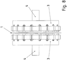
Figur 8 ist eine zurFigur 7 zugehörige Seitenansicht gezeigt. - In der
Figur 9 ist die elektrische Versorgung der zweiseitig speisbaren Elektromaschine, also des Antriebs, schematisch gezeigt. - In der
Figur 10 die Differenz der rotorseitig elektrisch eingespeisten Frequenz ωr und der statorseitig elektrisch eingespeisten Frequenz ωs als Funktion der mechanischen Drehzahl Ω, also als Funktion der mechanischen vorgegebenen Solldrehzahl ΩSoll gezeigt. - In der
Figur 11 ist eine hysteresebehaftete Kennlinie der rotorseitig elektrisch eingespeisten Frequenz ωr als Funktion der mechanischen Drehzahl Ω dargestellt. - In der
Figur 12 ist die zugehörige hysteresebehaftete Kennlinie der statorseitig elektrisch eingespeisten Frequenz ωs als Funktion der mechanischen Drehzahl Ω dargestellt, wobei über einen großen Drehzahlbereich hinweg der Wert ωs=0 vorgesehen ist und somit Eisenverluste reduzierbar sind. Der Drehzahlbereich reicht hierbei von einer der minimalen Rotorfrequenz ωr, min entsprechenden Drehzahl Ω bis zu der synchronen Drehzahl Ω0. - In der
Figur 13 ist die rotorseitige feldorientierte Regelung gezeigt, wobei aus den erfassten Ausgangsströmen und der erfassten Ausgangsspannung der Feldorientierungswinkel ϕS und die Komponente Ψsd bestimmt wird. - In der
Figur 14 ist die rotorseitige Regelstrecke zum Hinregeln der mechanischen Drehzahl Ωist auf den Sollwert Ω hin gezeigt. - In der
Figur 15 ist die statorseitige U/f-Steuerung und der Magnetisierungsstromregler (Regler für isd) dargestellt, wobei in einer Lookup-Table die hysteresebehaftete Kennlinie der statorseitig elektrisch eingespeisten Frequenz ωs als Funktion der mechanischen Drehzahl Ω hinterlegt ist, so dass aus der Drehzahlvorgabe eine Spannungskomponente Usq bestimmbar ist - In
Figur 16
- In the
FIG. 1 is a schematic cross section through a drive according to the invention with printedcircuit board 1 shown. - In the
FIG. 2 thecircuit board 1 is shown in a schematic plan view. - In the
FIG. 3 an inventive winding scheme for a first phase U is shown in a first layer of the multilayer printed circuit board. - In the
FIG. 4 an inventive winding scheme for the first phase U is shown in a second layer of the multilayer printed circuit board. - In the
FIG. 5 is shown an abrasive supply of the rotor winding, wherein a three-phase rotary current is transmitted. - In the
FIG. 6 is shown a single-phase inductive supply of the rotor winding. - In the
FIG. 7 is a plan view of the shown with stator, in which a Einzelzahnbewicklung is executed. - In the
FIG. 8 is one toFIG. 7 shown side view. - In the
FIG. 9 is the electrical supply of the bilaterally fed electric machine, so the drive, shown schematically. - In the
FIG. 10 the difference of the rotor side electrically fed frequency ω r and the stator side electrically fed frequency ω s as a function of the mechanical speed Ω, that is shown as a function of the mechanical predetermined target speed Ω target . - In the
FIG. 11 is a hysteresis characteristic of the rotor side electrically fed frequency ω r shown as a function of the mechanical speed Ω. - In the
FIG. 12 is the associated hysteresis characteristic of the stator side electrically fed frequency ω s represented as a function of mechanical speed Ω, over a large speed range across the value ω s = 0 is provided and thus iron losses can be reduced. The speed range extends from one of the minimum rotor frequency ω r, min corresponding speed Ω up to the synchronous speed Ω 0 . - In the
FIG. 13 the rotor-side field-oriented control is shown, wherein the field orientation angle φ S and the component Ψ sd are determined from the detected output currents and the detected output voltage. - In the
FIG. 14 is the rotor-side controlled system for advancing the mechanical speed Ω is shown to the setpoint Ω out. - In the
FIG. 15 is the stator-side U / f control and the magnetization current controller (controller for i sd ) shown, in a lookup table the hysteresis characteristic of the stator side electrically fed frequency ω s is stored as a function of mechanical speed Ω, so that from the speed specification a Voltage component U sq is determinable - In
FIG. 16 is the definition of angles illustrated.
Wie in
Eine Leiterplatte 1, insbesondere Multilayer-Leiterplatte, ist mit der Welle 4 drehfest verbunden, wobei die Normalenrichtung der Leiterplattenebene parallel zur Wellenachse der Welle 4 ausgerichtet ist.A
Wie auch in
Jeder Statorkern 3 ist topfartig ausgeformt und weist an seinem Topfrand die in Umfangsrichtung voneinander regelmäßig beabstandeten, axial gerichteten Zahnvorsprünge mit jeweiliger Einzelzahnwicklung auf.Each
Die Zahnvorsprünge und somit die Einzelzahnwicklungen stehen sich axial gegenüber, so dass das von einer Einzelzahnwicklung erzeugte Magnetfeld größtenteils in einen gegenüberstehenden Zahnvorsprung eingeleitet wird.The tooth projections and thus the single tooth windings face each other axially, so that the magnetic field generated by a single tooth winding is for the most part introduced into an opposing tooth projection.
Somit ist durch den mittels der Statorkerne 3 gebildeten Stator der Stator einer Axialflussmaschine ausbildbar und ein Drehfeld erzeugbar, das mit einem aktiven Bereich der Leiterplatte 1 zusammenwirkt. Hierzu sind die Einzelzahnwicklungen als Drehfeldwicklung verschaltet und somit entsprechend bestromt.Thus, the stator of an axial flux machine can be formed by the stator formed by means of the
Der aktive Bereich, also Aktivbereich 22, der Leiterplatte 1 ist ein ringförmiger Teilbereich der Leiterplatte, in welchem die als Leiterbahnen der Leiterplatte ausgeführten Wicklungsleitungen 23 der rotorseitig vorgesehenen Wicklung, radial verlaufen. Der ringförmige Teilbereich ist also durch einen Radialabstandsbereich der Leiterplatte kennzeichenbar. Das von den Zähnen, also Zahnvorsprüngen, der Statorkerne 3 erzeugte Hauptfeld durchdringt den von der Leiterplatte 1 axial überdeckten Bereich. Somit überdecken also die Zähne der Statorkerne 3 denjenigen radialen Bereich, der vom aktiven Bereich der Leiterplatte 1 radial überdeckt wird.The active region, that is
Auf größerem Radialabstand als der aktive Bereich ist der Umlenkbereich 21 angeordnet, insbesondere radial äußerer Umlenkbereich, also Wickelkopfbereich. Auf kleinerem Radialabstand als der aktive Bereich ist der Umlenkbereich 26 angeordnet, insbesondere radial innerer Umlenkbereich, also Wickelkopfbereich.At a greater radial distance than the active region of the
Bei weiteren erfindungsgemäßen Ausführungsbeispielen ist stehen sich die Zahnvorsprünge nicht direkt axial gegenüber. Sie können auch um eine halbe Zahnteilung gegeneinander verdreht sein. Vorteiligerweise ergibt sich dann prinzipiell die doppelte nutzbare Nutzzahl. Das Feld ist dann allerdings nicht mehr rein axial gerichtet. Dies ist für einen statorseitigen zweisträngigen Wicklungsaufbau nutzbar. In further embodiments of the invention, the tooth projections are not directly opposite to each other axially. You can also be rotated by half a tooth pitch against each other. Advantageously, then in principle results in twice the usable usable number. The field is then no longer directed purely axially. This is usable for a stator-side two-strand winding structure.
Auf jede der Statorhälften wird dabei ein Strang gewickelt und durch die Verdrehung der Hälften gegeneinander ergibt sich der notwendige geometrische Versatz um einen elektrischen Winkelbetrag von 90°, um ein Drehfeld auszubilden. Die Einzelzahnwicklung am Stator wirkt dann nicht mehr wie eine klassische konzentrierte Wicklung, insbesondere also Bruchlochwicklung, sondern wie eine Ganzlochwicklung. Dies wird in Verbindung mit einer Rotorplatine mit konzentrierten Wicklungen, insbesondere also Bruchlochwicklung, verwendet.On each of the stator halves while a strand is wound and by the rotation of the halves against each other results in the necessary geometric offset by an electrical angle of 90 ° to form a rotating field. The single-tooth winding on the stator then no longer acts like a classic concentrated winding, in particular so Bruchlochwicklung, but like a ganzlochwicklung. This is used in conjunction with a rotor board with concentrated windings, in particular so Bruchlochwicklung.
Wie bei dem erfindungsgemäßen Ausführungsbeispiel in
Radial innerhalb des Aktivbereichs 22, insbesondere radial innerhalb des vom Umlenkbereich 26 überdeckten Radialbereichs ist ein mit Bauelementen bestückter Bereich 25 der Leiterplatte 1 angeordnet. Somit ist eine elektronische Schaltung auf der mit der Welle 4 im Verbindungsbereich 24 verbundenen Leiterplatte 1 anordenbar.Radially within the
Wie in
Wie in
Dabei ist eine Leistungsstufe 52, insbesondere Verstärker, mit Leistungshalbleiterschaltern stationär, also drehfest mit dem Statorkern 3 verbunden, angeordnet, wobei die Leistungsstufe von einer Steuerelektronik 53 mit pulsweitenmodulierten Ansteuersignalen für die Leistungshalbleiterschalter angesteuert wird und der mehrphasige Ausgangsstrom der Leistungsstufe 52 den Schleifübertragungsmitteln 51 zugeführt wird.In this case, a
Als alternatives erfindungsgemäßes Ausführungsbeispiel ist statt der Schleifübertragung eine induktive Übertragung in
Hierfür ist eine Sekundärwicklung 61 drehfest mit der Welle 4 verbunden, wobei die auf der Leiterplatte 1 angeordnete elektronische Schaltung elektrisch versorgbar ist über die induktive Kopplung.For this purpose, a secondary winding 61 is rotatably connected to the
Die induktiv mit der Sekundärwicklung 61 gekoppelte Primärwicklung 62 ist drehfest mit einem der Statorkerne 3 verbunden. Die Primärwicklung 62 wird von einem Wechselrichter 63 gespeist, der von einer Steuerelektronik 64 angesteuert wird.The inductively coupled to the secondary winding 61 primary winding 62 is rotatably connected to one of the
Somit ist in die Primärwicklung 62 ein mittelfrequenter Strom einprägbar, insbesondere mit einer Frequenz zwischen 10 und 1000 kHz, vorzugsweise mit einer Frequenz zwischen 100 und 200 kHz.Thus, in the primary winding 62, a medium-frequency current can be imprinted, in particular with a frequency between 10 and 1000 kHz, preferably with a frequency between 100 and 200 kHz.
Der Sekundärwicklung 61 ist eine Kapazität in Reihe und/oder parallel zuschaltbar, so dass die zugehörige Resonanzfrequenz im Wesentlichen der eingeprägten Mittelfrequenz entspricht. Auf diese Weise sind trotz Schwankungen der induktiven Kopplungsstärke möglichst gleichmäßig hohe Wirkungsgrade erreichbar.The secondary winding 61 is a capacity in series and / or connected in parallel, so that the associated resonant frequency substantially corresponds to the impressed center frequency. In this way, evenly high efficiencies can be achieved despite fluctuations in the inductive coupling strength.
Ein Leistungsstellglied ist auf der Leiterplatte 1 im Bereich 25 vorgesehen. Somit ist der elektrische Leistungsfluss von der Sekundärwicklung 61 über das Leistungsstellglied hin zum aktiven Bereich 22 der Leiterplatte 1 steuerbar. Im Bereich 25 ist außerdem eine Steuerelektronik angeordnet, welche Ansteuersignale für das Leistungsstellglied aufweist. Das Leistungsstellglied ist als Stromrichter ausgeführt. Wegen der räumlichen Nähe zum Aktivbereich 22 ist das Leistungsstellglied sehr niederinduktiv angebunden an den Aktivbereich 22. Die Induktivität der Zuleitung der elektrischen Energie vom Leistungsstellglied zum Aktivbereich 22 ist kleiner als die Induktivität des Aktivbereichs 22 samt Umlenkbereichen 21 und 26, also der Rotorwicklung. Insbesondere ist sie geringer als ein Zehntel der Induktivität der Rotorwicklung.A power actuator is provided on the
Des Weiteren werden Strom, Temperatur und/oder Spannung der Rotorwicklung erfasst und der Steuerelektronik im Bereich 25 der Leiterplatte 1 zugeführt.Furthermore, current, temperature and / or voltage of the rotor winding are detected and supplied to the control electronics in the
Wie in
Die Zahnspulen sind also als Formspulen auf den jeweiligen zahnartigen Vorsprung aufgesteckt. Die Statorkerne 3 sind als Formteile ausgeführt, insbesondere aus Ferrit oder einem ferromagnetischen Werkstoff ausgeführt. Die magnetischen Eigenschaften der Statorkerne sind isotrop. Als Werkstoff der Statorkerne 3 werden bevorzugt SMC-Magnetkreismaterialien eingesetzt, also Soft-Magnetik-Composite-Materialien.The tooth coils are thus attached as a form of coils on the respective tooth-like projection. The
Bei Dauermagneterregung am Stator wird alternativ Stahl eingesetzt.For permanent magnet excitation on the stator steel is alternatively used.
Da somit statorseitig eine Drehfeldwicklung vorgesehen ist und rotorseitig ebenfalls eine Drehfeldwicklung im Aktivbereich 22 ausgeführt ist, liegt somit eine zweiseitig eingespeiste Drehfeldmaschine mit eisenlosem Rotor vor. Der Drehzahlstellbereich ist verglichen mit einer einseitig eingespeisten Drehfeldmaschine doppelt so groß, wenn die Frequenzanteile beide gleich groß sind und jeweils der Speisefrequenz der einseitig gespeisten Drehfeldmaschine entsprechen. Thus, since a rotating field winding is provided on the stator side and a rotary field winding in the
Die Leiterplatte 1 weist einen kreisförmigen Rand auf. Somit ist sie als Scheibe ausgeführt, insbesondere also Lochscheibe, wobei die Welle 4 in dem mittig angeordneten Loch durchgeführt ist.The
Die Leiterplatte 1 weist ein elektrisch isolierendes Trägermaterial auf, wobei hierzu vorzugsweise Epoxidharz verwendet wird. Jede der Lagen, also Layer, weist metallische Leiterbahnen auf, wobei hierzu vorzugsweise Kupfer oder eine Kupfer-haltige Legierung verwendet wird.The printed
Somit ist der Rotor eisenlos ausgeführt, also ohne Blechpaket. Das Trägermaterial weist eine im Wesentlichen mit Luft vergleichbare spezifische magnetische Permeabilität auf. Da das Trägermaterial nur eine geringe Masse aufweist, weist der Rotor insgesamt ein sehr geringes Trägheitsmoment auf.Thus, the rotor is ironless, so without laminated core. The carrier material has a specific magnetic permeability substantially comparable to that of air. Since the carrier material has only a small mass, the rotor has a very low moment of inertia overall.
Die Durchkontaktierungen sind elektrische Verbindungen von in Normalenrichtung der Leiterplatte voneinander beabstandeten Endpunkten der Leiterbahnen. Vorzugsweise wird hierzu ein Bohrloch in die Leiterplatte eingebracht, dessen Wandung metallisiert wird, also mit einer Metallschicht überzogen wird.The plated-through holes are electrical connections of end points of the strip conductors which are spaced from one another in the normal direction of the printed circuit board. Preferably, for this purpose, a borehole is introduced into the printed circuit board whose wall is metallized, that is coated with a metal layer.
Bei weiteren erfindungsgemäßen Ausführungsbeispielen ist als Leiterbahn ein jeweiliges Kupferprofil verwendet, welches in einem elektrisch isolierenden Basismaterial eingebettet ist. Vorzugsweise ist das Kupferprofil aus einem Stanz-Biegeteil oder aus einem Stranggussprofil als Stanz-Biegeteil und das Basismaterial ist Epoxidharz. Das Kupferprofil weist einen dicken Querschnitt auf, so dass eine hohe Stromtragfähigkeit erreichbar ist.In further embodiments of the invention, a respective copper profile is used as the conductor track, which is embedded in an electrically insulating base material. Preferably, the copper profile of a stamped and bent part or of a continuous cast profile as stamped and bent part and the base material is epoxy resin. The copper profile has a thick cross-section, so that a high current carrying capacity can be achieved.
Bei dem erfindungsgemäßen Verfahren wird eine zweiseitig einspeisbare Drehfeldmaschine, wie beispielhaft die oben beschriebene Elektromaschine 96, statorseitig mit einer als Drehfeldwicklung ausgeführten Statorwicklung vorgesehen, die von einem Wechselrichter 94, der statorseitig angeordnet ist, gespeist wird und ein Blechpaket aufweist. Dieser Wechselrichter 94 weist ansteuerbare Leistungshalbleiter auf, deren Ansteuersignale von einer Steuerelektronik erzeugt werden, die einen Regler aufweist. Dabei arbeitet die Regelung des Reglers als U/f-Steuerung.In the method according to the invention, a two-sided injectable induction machine, such as the above-described
Rotorseitig ist eine als Drehfeldwicklung ausgeführte eisenlose Rotorwicklung vorgesehen, die von einem weiteren Wechselrichter 95, der rotorseitig angeordnet ist, gespeist wird. Dieser Wechselrichter weist ansteuerbare Leistungshalbleiter auf, deren Ansteuersignale von einer ebenfalls auf dem Rotor angeordneten Steuerelektronik erzeugt werden, die einen Regler aufweist. Dabei arbeitet diese rotorseitig angeordnete Regelung als feldorientierte Regelung.On the rotor side, an ironless rotor winding designed as a rotating field winding is provided, which is fed by a
Die rotorseitige Steuerelektronik samt Wechselrichter 95 ist induktiv oder mittels Schleifübertragung elektrisch versorgt, wie in den
Die Speisung beider Wechselrichter (94, 95) ist aus einem Zwischenkreiskondensator 93 ausführbar, welcher über einen Gleichrichter 92 aus einer Wechselspannungsquelle 91, insbesondere Versorgungsnetz, speisbar ist.The supply of both inverters (94, 95) can be executed from a
Das Gleichungssystem der Maschine lautet in Raumzeigerdarstellung im allgemeinen Koordinatensystem (hochgestellter Index K): 


Der Zusammenhang für Winkel und Drehzahlen lautet 


The relationship for angles and speeds is
Für die mechanische Drehzahl gilt 
Anstatt nun rotorseitig und statorseitig insgesamt vier Stromregler (ird, isd, irq, isq) zu verwenden, wird erfindungsgemäß eine verbesserte Stabilität bei der Regelung der Elektromaschine erreicht, indem rotorseitig zwei Stromregler feldorientiert arbeiten und statorseitig nur ein feldorientierter Magnetisierungsstromregler (Regler für isd) und eine U/f-Steuerung, die die Spannung "usq" erzeugt, wodurch statorseitig ein sensorloses Regelungskonzept aufgebaut ist.Instead of using rotor-side and stator-side altogether four current regulators (i rd , i sd , i rq , i sq ), according to the invention an improved stability in the regulation of the electric machine is achieved by two current regulators operating field-oriented on the rotor side and only one field-oriented magnetization current regulator (controller) on the stator side for i sd ) and a V / f control, which generates the voltage "u sq ", whereby a sensorless control concept is established on the stator side.
Die U/f-Steuerung basiert dabei auf der Vorgabe von drehzahlabhängigen Frequenzsollwerten ωs, Soll. Wie in
gemäß einer Kennlinie, die in einer Lookup-Table hinterlegt ist, insbesondere mittels zu interpolierender Wertepaare, bestimmt. Diese Kennlinie ist in
according to a characteristic which is stored in a look-up table, in particular by means of value pairs to be interpolated. This characteristic is in
Die synchrone Drehzahl Ω0 bei der erfindungsgemäß zweiseitig einspeisbaren Elektromaschine ist doppelt so groß wie die synchrone Drehzahl bei einer nur einseitig einspeisbaren Elektromaschine.The synchronous speed Ω 0 in the case of the electric machine that can be fed in on two sides is twice as high as the synchronous speed in the case of an electric machine that can be fed in only on one side.
Wie in
Zur Bildung der in Richtung des momentbildenden Stromanteils isq vorgesehenen Komponente Usq der Statorspannung wird der durch die Multiplikation entstandene Ergebniswert um Rs * Isq,ist vermindert.To form the component U sq of the stator voltage provided in the direction of the torque-generating current component i sq , the result value resulting from the multiplication is reduced by R s * I sq .
Zur Bildung der in Richtung des magnetisierungsbildenden Stromanteils isd vorgesehenen Komponente Usd wird die Abweichung zwischen dem Sollwert isd,soll und dem Istwert isd,ist einem Integrierglied zugeführt. Somit ist hier ein Regler mit integrierendem Anteil vorgesehen, wobei als Regler ein linearer Regler, wie PI-Regler, eingesetzt ist.To form the provided in the direction of magnetization forming current component i sd sd U component, the deviation between the target value i sd, is intended and the actual value i sd, is fed to an integrator. Thus, a controller with integrating portion is provided here, as a controller, a linear controller, such as PI controller is used.
Aus den beiden Spannungskomponenten wird ein Statorspannungsraumzeiger gebildet, der in der Richtung des um γ erhöhten Feldorientierungswinkels vorgesehen ist. Ein solcher Raumzeiger (UsU, UsV, UsW) wird dann der statorseitigen Drehfeldwicklung, also der Statorwicklung, zugeführt.From the two voltage components, a stator voltage space pointer is formed which is provided in the direction of the field orientation angle increased by γ. Such a space vector (U sU , U sV , U sW ) is then fed to the stator-side field winding, ie the stator winding.
Wie in
Die Statorfrequenz wird über die Spannungskomponente usq eingeprägt, wie in
Hierzu wird - wie in
Der Sollwert ird,Soll für den magnetisierungsbildenden Stromanteil wird auf Null gesetzt und die Abweichung zum entsprechenden Istwert einem Integrierglied zugeführt, dessen Ausgangssignal auf den Entkoppelterm ed aufsummiert wird. Somit ist auch hier ein Regler mit integrierendem Anteil vorgesehen, wobei als Regler ein linearer Regler, wie PI-Regler, eingesetzt ist.The setpoint i rd, setpoint for the magnetization-forming current component is set to zero and the deviation from the corresponding actual value is fed to an integrator whose output signal is summed up on the decoupling term e d . Thus, a controller with integrating portion is also provided here, with a linear controller, such as PI controller, is used as a controller.
Aus den beiden so gebildeten Spannungskomponenten (Urd, Urq) wird ein in Richtung des Feldorientierungswinkels ausgerichteter Spannungsraumzeiger erzeugt und dieser Spannungsraumzeiger (UrU, UrV, UrW) wird dann der rotorseitigen Drehfeldwicklung, also der Rotorwicklung, zugeführt.From the two voltage components (U rd , U rq ) thus formed, a voltage space vector aligned in the direction of the field orientation angle is generated and this voltage space vector (U rU , U rV , U rW ) is then fed to the rotor-side field winding, ie the rotor winding.
Wie in
Hierzu werden die Stromkomponente ira und irb des erfassten Stromraumzeigers dem Ohmschen Widerstand der Rotorwicklung RR multipliziert und die Differenz zur jeweiligen Stromkomponente Ura und Urb gebildet. Die so gebildeten Produkte werden einem jeweiligen Integrierglied zugeführt und die beiden Ausgangssignale der Integrierglieder als komplexe Größe, insbesondere also als zweidimensionaler Raumzeiger, dargestellt. Die komplexe Größe wird mit LS/Lh multipliziert und zum Ergebniswert der ebenfalls komplex dargestellte, mit (Lh - LS*Lr/Lh) multiplizierte Stromraumzeiger (ira + j * irb) addiert. Auf diese Weise ist somit der Statorfluss bestimmt, also der Feldorientierungswinkel ϕs und der die Magnetisierung bildenden Anteil des magnetischen Flussraumzeigers.For this purpose, the current component i ra and i rb of the detected current space vector are multiplied by the ohmic resistance of the rotor winding R R, and the difference to the respective current component U ra and U rb is formed. The products thus formed are supplied to a respective integrator and the two output signals of the integrators as a complex size, in particular as a two-dimensional space vector represented. The complex quantity is multiplied by L S / L h and added to the result value of the current-space vector (i ra + j * i rb ), which is also complex and multiplied by (L h -L S * L r / L h ). That way is Thus, the stator flux determined, ie the field orientation angle φ s and the magnetization forming portion of the magnetic flow space vector.
Kleine mechanische Drehzahlen sind bei der zweiseitig gespeisten Elektromaschine nicht zwingend mit kleinen elektrischen Frequenzen verbunden im Unterschied zu einseitig eingespeisten Maschinen.Small mechanical speeds are not necessarily associated with small electrical frequencies in the two-sided powered electric machine in contrast to unilaterally fed machines.
Besondere Vorteil der Erfindung liegt darin, dass der für die Regelung notwendige Feldorientierungswinkel, also die Lage des Feldes, mit einem recht einfachen mathematischen Modell bestimmbar ist. Diese Bestimmung ist bei der Erfindung für auch für kleine mechanische Drehzahlen und sogar bis zum Stillstand ausführbar, da die elektrische Frequenz, insbesondere Rotorfrequenz, nie unter einen Minimalwert sinkt. Beispielhaft beträgt dieser Minimalwert zwischen 5 Hz und 15 Hz, insbesondere zwischen 10 Hz und 12 Hz. Besonders vorteilhaft ist, dass das sogenannte, in den Figuren dargestellte Spannungsmodell für die Berechnung des Feldorientierungswinkels verwendbar ist.A particular advantage of the invention is that the field orientation angle necessary for the control, that is to say the position of the field, can be determined with a rather simple mathematical model. This provision can be carried out in the invention for even small mechanical speeds and even to a standstill, since the electrical frequency, in particular rotor frequency, never falls below a minimum value. By way of example, this minimum value is between 5 Hz and 15 Hz, in particular between 10 Hz and 12 Hz. It is particularly advantageous that the so-called voltage model shown in the figures can be used for the calculation of the field orientation angle.
Wie in den
Zwei dieser drei Stromregler erfüllen dabei diejenigen Forderungen, die auch bei einer einseitig gespeisten Maschine notwendig wären. Diese Forderungen umfassen zum Einen einen konstanten Magnetisierungszustand und zum Anderen die Einstellbarkeit des Drehmoments bei konstanter Magnetisierung. Der Magnetisierungszustand wird hier vom Stromanteil isd bestimmt, wie in
Wir in
Die erfindungsgemäß verwendete Kennlinie ermöglicht, dass aus der gemessenen oder geschätzten mechanischen Drehzahl die einzustellende Spannung usq ermittelt wird und der Maschine vorgebbar ist, wie in
Wie in den
In
In
Die hier vorgestellten Kennlinien sehen eine Absenkung der Statorspeisefrequenz auf 0 Hz über einen weiten Drehzahlbereich, nämlich den Bereich zwischen Ωmin / Ω0 und 1, vor, wie in
Diese Absenkung der Frequenz auf 0 Hz beginnt bei geringen Drehzahlbeträgen, die eine definierte Rotorminimalfrequenz ωr, min ermöglichen. Mittels des Einhaltens der Minimalfrequenz ωr, min ist geberlose Berechnung des für die Regelung notwendigen Feldorientierungswinkels mit einem sog. Rotorspannungsmodell ermöglicht, wie in
Bei diesen kleinen Frequenzen ist somit die EMK, also elektromotorische Kraft, derart gering, dass eine darauf basierte Bestimmung der Rotorwinkellage nicht mehr brauchbar ist und somit hierzu eigentlich ein Winkelsensor verwendet werden muss oder ein anderes mathematisches Berechnungs- oder Schätzverfahren, welches nicht auf die Bestimmung der EMK angewiesen ist.At these low frequencies, the EMF, ie the electromotive force, is so low that a determination of the rotor angle position based thereon is no longer useful and therefore an angle sensor or an other mathematical calculation or estimation method, which does not depend on the determination, has to be used the EMK is instructed.
Die im Drehzahlbereich um Null in den
Das Potential des erfindungsgemäßen Regelungsverfahrens liegt zum einen in der Möglichkeit, zweiseitig eingespeiste Drehfeldmaschinen bis hin zu kleinsten Drehzahlen und auch im Stillstand geberlos regelbar zu machen. Zum andern ist eine Minimierung des Rotorstroms erreichbar. Außerdem ist eine Verbesserung der Bauleistung von Übertragungssystemen und der Effizienz des Antriebs erreichbar. Weiterhin wirkt das erfindungsgemäße Verfahren, insbesondere die Absenkung der Statorfrequenz auf 0 Hz, bei Maschinen mit eisenlosem Rotor besonders vorteilhaft. Der Wirkungsgrad wird dadurch deutlich verbessert. Denn in diesem Bereich treten in der gesamten Maschine keinerlei Eisenverluste auf, weil der mit Frequenz beaufschlagte Rotor eisenlos ist und der Stator nicht mit Frequenz beaufschlagt wird.The potential of the control method according to the invention is on the one hand in the ability to make two-sided fed induction machines down to the lowest speeds and even at standstill controllable. On the other hand, a minimization of the rotor current can be achieved. In addition, an improvement in the performance of transmission systems and the efficiency of the drive can be achieved. Furthermore, the method according to the invention, in particular the lowering of the stator frequency to 0 Hz, is particularly advantageous in machines with an ironless rotor. The efficiency is significantly improved. Because in this area no iron losses occur in the entire machine, because the frequency acted rotor is ironless and the stator is not subjected to frequency.
Statt auf einer rotorischen Elektromaschine ist bei einem anderen erfindungsgemäßen Ausführungsbeispiel die Erfindung auch bei einem Linearmotor in analoger Weise ausführbar.Instead of on a rotary electric machine, in another embodiment of the invention, the invention also in a linear motor in an analogous manner executable.
Bei weiteren erfindungsgemäßen Ausführungsbeispielen sind in
- 1 Leiterplatte, insbesondere Multilayer-Leiterplatte1 circuit board, in particular multilayer printed circuit board
- 2 Mittenebene2 middle level
- 3 Statorkern3 stator core
- 4 Welle4 wave
- 5 Lager5 bearings
- 6 Lager6 bearings
- 21 Umlenkbereich, insbesondere radial äußerer Umlenkbereich, Wickelkopfbereich21 deflection, in particular radially outer deflection, winding head
- 22 Aktivbereich22 active area
- 23 Wicklungsleitung23 winding line
-
24 Verbindungsbereich zur Welle 424 connection area to the
shaft 4 - 25 mit Bauelementen bestückter Bereich der Leiterplatte25 equipped with components area of the circuit board
-
26 Umlenkbereich, insbesondere radial innerer Umlenkbereich, Wickelkopfbereich 51 Schleifübertragungsmittel26 deflection region, in particular radially inner deflection region, winding
head region 51 grinding transfer means - 52 Leistungsstufe, insbesondere Verstärker, mit Leistungshalbleiterschaltern52 power stage, in particular amplifier, with power semiconductor switches
- 53 Steuerelektronik mit pulsweitenmodulierten Ansteuersignalen für die Leistungshalbleiterschalter53 Control electronics with pulse width modulated drive signals for the power semiconductor switches
- 61 Sekundärwicklung61 secondary winding
- 62 Primärwicklung62 primary winding
- 63 Wechselrichter63 inverters
- 64 Steuerelektronik64 control electronics
- 71 Einzelzahnwicklung71 single tooth winding
- 91 Wechselspannungsquelle, Versorgungsnetz91 alternating voltage source, supply network
- 92 Gleichrichter92 rectifier
- 93 Zwischenkreiskondensator93 DC link capacitor
- 94 statorseitiger Wechselrichter94 stator-side inverter
- 95 rotorseitiger Wechselrichter95 rotor-side inverter
- 96 Elektromaschine, zweiseitig speisbare96 Electric machine, feedable on two sides
- isd Feldbildende Stromkomponente, die in der Statorwicklung fließt i sd Field-forming current component flowing in the stator winding
- ird Feldbildende Stromkomponente, die in der Rotorwicklung fließt i rd Field-forming current component flowing in the rotor winding
- isq Drehmomentbildende Stromkomponenten, die in der Statorwicklung fließt i sq Torque-forming current components flowing in the stator winding
- irq Drehmomentbildende Stromkomponente, die in der Rotorwicklung fließt i rq Torque- forming current component flowing in the rotor winding
- usd Komponente der Statorspannung, mit der die feldbildende Stromkomponente am Stator eingestellt wird u sd Component of the stator voltage used to set the field-forming current component on the stator
- urd Komponente der Rotorspannung mit der (nach Entkopplung durch ed) die feldbildende Stromkomponente am Rotor eingestellt wird (im Konzept auf Null ausgeregelt wird) u rd component of the rotor voltage with which (after decoupling by e d ) the field-forming current component is set on the rotor (in the concept is adjusted to zero)
- urq Komponente der Rotorspannung mit der (nach Entkopplung durch eq) die drehmomentbildende Komponente des Rotorstroms eingestellt wird. u rq component of the rotor voltage with which (after decoupling by e q ) the torque- forming component of the rotor current is set.
- usq Komponente der Statorspannung mit deren Hilfe die Frequenz über die Lookup-Table eingestellt wird u sq Component of the stator voltage with the aid of which the frequency is set via the lookup table
- Qmin erste DrehzahlQ min first speed
- Ω0 zweite DrehzahlΩ 0 second speed
- ωr, min Rotorminimalfrequenzω r, min rotor minimum frequency
Claims (15)
- Method for operating an electric machine (96) which has a rotating part, in particular a rotor, that is movable relative to a stator,
wherein the mechanical speed of the rotating part relative to the stator, in particular the rotational speed of the rotor, is detected or estimated, in particular by control electronics (53, 64),
wherein a winding, that is to say a rotor winding, is arranged on the rotating part, said rotor winding being designed as a rotating field winding,
wherein a stator winding is arranged on the stator, said stator winding likewise being designed as a rotating field winding,
wherein the rotor has an active region (22), in particular for generating torque when the active region (22) interacts with the magnetic field generated by the stator,
wherein the active region (22) has conductor tracks of a multilayer printed circuit board (1), that is to say of a printed circuit board (1) composed of multiple layers, through which conductor tracks an electric current can flow,
wherein the rotor winding has a lower inductance than the stator winding,
in particular wherein the stator winding has a ferrous coil core and/or a laminated core,
wherein each rotating field winding is fed by a respective inverter (63), that is to say in particular the rotating-part-side and/or rotor-side rotating field winding is fed by a rotating-part-side and/or rotor-side inverter (95) and the stator-side rotating field winding is fed by a stator-side inverter (94),
wherein an electrical frequency ωS,Soll of the voltage fed from the stator-side inverter (63) to the stator winding, in particular the electrical frequency of the rotating field generated on the stator side, that is to say in particular the stator supply frequency, is determined from the mechanical rotational speed Ω according to a characteristic curve,
in particular wherein the characteristic curve represents a hysteresis-affected dependence of the electrical frequency ωS,Soll on the mechanical speed,
wherein the characteristic curve is designed such that, in a rotational speed range at least from Ωmin to Ω0, the magnitude of the stator supply frequency ωS is lowered to less than the magnitude of a minimum frequency ωS,min and/or is lowered to the magnitude of a minimum frequency of zero hertz, in particular wherein the minimum frequency has a constant magnitude in the rotational speed range from Ωmin to Ω0,
and wherein the characteristic curve is designed such that the magnitude of the supply frequency ωS of the stator winding is selected to be greater than the magnitude of the minimum frequency if the mechanical rotational speed Ω exceeds the second rotational speed Ω0,
wherein Ωmin is a first rotational speed, and
wherein Ω0 is a second rotational speed, the magnitude of the second rotational speed Ω0 being greater than the magnitude of the first rotational speed,
in particular wherein the rotational speed range covered by the hysteresis is limited in terms of magnitude by the magnitude of the first rotational speed Ωmin,
wherein the magnitude of the electrical rotor-side supply frequency ωr does not fall below the magnitude of a non-vanishing minimum value ωr,min, in particular in order to ensure an EMF-based rotor position detection,
characterized in that
electrical power can be supplied via an inductive coupling to the active region (22), the rotor winding and/or the electronic circuit comprising electronic components mounted on the printed circuit board (1),
wherein the rotor is connected to a secondary winding (61) which is inductively coupled to a primary winding (62) that is connected to the stator in a rotationally fixed manner, wherein a medium-frequency current, preferably having a frequency between 100 and 200 kHz, is impressed in the primary winding (62) by an electrical feed-in which has a gyrator acting as a current source. - Method for operating an electric machine (96) which has a rotating part, in particular a rotor, that is movable relative to a stator,
wherein the mechanical speed of the rotating part relative to the stator, in particular the rotational speed of the rotor, is detected or estimated, in particular by control electronics (53, 64),
wherein a winding, that is to say a rotor winding, is arranged on the rotating part, said rotor winding being designed as a rotating field winding,
wherein a stator winding is arranged on the stator, said stator winding likewise being designed as a rotating field winding,
wherein the rotor has an active region (22), in particular for generating torque when the active region (22) interacts with the magnetic field generated by the stator,
wherein the active region (22) has conductor tracks of a multilayer printed circuit board (1), that is to say of a printed circuit board (1) composed of multiple layers, through which conductor tracks an electric current can flow,
wherein the rotor winding is referred to as the first winding if it has a higher inductance than the stator winding, and wherein the stator winding is referred to as the first winding if it has a higher inductance than the rotor winding,
wherein each rotating field winding is fed by a respective inverter (63), that is to say in particular the rotating-part-side and/or rotor-side rotating field winding is fed by a rotating-part-side and/or rotor-side inverter (95) and the stator-side rotating field winding is fed by a stator-side inverter (94),
wherein an electrical frequency ωS,Soll of the voltage fed from the stator-side inverter (63) to the stator winding, in particular the electrical frequency of the rotating field generated on the stator side, that is to say in particular the stator supply frequency, is determined from the mechanical rotational speed Ω according to a characteristic curve,
in particular wherein the characteristic curve represents a hysteresis-affected dependence of the electrical frequency ωS,Soll on the mechanical speed,
wherein the characteristic curve is designed such that, in a rotational speed range at least from Ωmin to Ω0, the stator supply frequency is lowered to less than a minimum frequency, wherein the supply frequency of the first winding is lowered to a minimum frequency, in particular a minimum frequency that is constant over time,
wherein the electrical rotor-side supply frequency ωr and the electrical stator-side supply frequency ωS are selected such that the sum of the two supply frequencies corresponds to the desired mechanical rotational speed ΩSoll, that is to say in particular is
that is to say in particular the available degree of freedom of the proportional composition of the summed supply frequencies is used in such a way that the losses are minimized,
wherein Ωmin is a first rotational speed, and
wherein Ω0 is a second rotational speed, the magnitude of the second rotational speed Ω0 being greater than the magnitude of first rotational speed,
and wherein the characteristic curve is designed such that the magnitude of the supply frequency ωs of the first winding is selected to be greater than the magnitude of the minimum frequency if the mechanical rotational speed Ω exceeds the second rotational speed Ω0,
in particular wherein the rotational speed range covered by the hysteresis is smaller in terms of magnitude than the magnitude of the first rotational speed Ωmin,
wherein the electrical rotor-side supply frequency ωr does not fall below a minimum value ωr,min, in particular in order to ensure an EMF-based rotor position detection,
characterized in that
electrical power can be supplied via an inductive coupling to the active region (22), the rotor winding and/or the electronic circuit comprising electronic components mounted on the printed circuit board (1),
wherein the rotor is connected to a secondary winding (61) which is inductively coupled to a primary winding (62) that is connected to the stator in a rotationally fixed manner, wherein a medium-frequency current, preferably having a frequency between 100 and 200 kHz, is impressed in the primary winding (62) by an electrical feed-in which has a gyrator acting as a current source. - Method according to claim 1 or 2,
characterized in that
the detachment from the minimum frequency takes place when leaving the armature adjustment range, in particular the basic adjustment range, of the rotor winding, that is to say in particular when the mechanical rotational speed Ω exceeds the second rotational speed Ω0. - Method according to at least one of the preceding claims,
characterized in that
the required field frequency is realized as far as possible in the rotor winding. - Method according to at least one of the preceding claims,
characterized in that
actuation signals are in each case fed to semiconductor switches of the respective inverter (63) by control electronics (53, 64), the respective control electronics (53, 64) comprising a control device. - Method according to at least one of the preceding claims,
characterized in that
the stator-side control device has a U/f control,
and in that
the rotating-part-side or rotor-side control device has a field-oriented control. - Method according to at least one of the preceding claims,
characterized in that
the minimum frequency is 0 Hz,
and/or in that
the first rotational speed Qmin is selected such that open and/or non-fed-back integrations of the field-oriented, in particular time-discrete, in particular numerically operating, control do not diverge,
and/or in that
the first rotational speed Ωmin is selected such that the electrical rotor-side supply frequency ωr,min being set according to the characteristic curve and the control does not fall below a minimum value, in particular wherein the minimum value is between 1 Hz and 20 Hz, in particular between 10 Hz and 15 Hz,
and/or in that
the second rotational speed Ω0 is the synchronous rotational speed of an electric machine (96) fed from one side,
or in that the second rotational speed Ω0 is equal to half the synchronous rotational speed of the electric machine (96) fed from two sides. - Method according to at least one of the preceding claims,
characterized in that
zero is predefined as the nominal value that is predefined on the rotor side for the magnetization-forming current component, in particular in order to reduce power loss. - Method according to at least one of the preceding claims,
characterized in that
the U/f control, the deviation of the mechanical detected or estimated rotational speed from the predefined rotational speed nominal value is fed to a control element which generates as an output signal the nominal value of the torque-forming current component on the rotor side,
wherein the deviation between this nominal value and the actual value of the torque-forming rotor-side current component is fed to a control element, in particular to an integrator element, from the output signal of which a voltage value is determined, in particular the component of the voltage space vector in the direction of the torque-forming current component, in particular with summing of the eq signal. - Method according to at least one of the preceding claims,
characterized in that
the field-oriented control comprises integrator elements, from the output signals of which the field orientation angle is determined,
in particular with summing of a component of the current space vector to the space vector represented by the output signals. - Electric motor for carrying out a method according to at least one of the preceding claims,
comprising a stator with stator cores (3) and a rotor arranged such as to be able to rotate relative to the stator,
wherein the rotor has an active region (22), in particular for generating torque when the active region (22) interacts with the magnetic field generated by the stator,
wherein the active region (22) has conductor tracks of a multilayer printed circuit board (1), that is to say of a printed circuit board (1) composed of multiple layers, through which conductor tracks an electric current can flow,
wherein an inverter (63) which feeds the active region (22) is arranged on the multilayer printed circuit board (1),
wherein electrical power can be supplied to the inverter (63) from a stator-side primary winding (62) via an inductive coupling,
wherein the conductor tracks of the multilayer printed circuit board (1) form a rotating field winding,
wherein the rotating field winding is designed as a loop winding or wave winding, that is to say in particular not as a concentrated winding,
characterized in that
electrical power can be supplied via an inductive coupling to the active region (22), the rotor winding and/or an electronic circuit comprising electronic components mounted on the printed circuit board (1),
wherein the rotor is connected to a secondary winding (61) which is inductively coupled to a primary winding (62) that is connected to the stator, in particular is connected thereto in a rotationally fixed manner,
wherein a medium-frequency current, preferably having a frequency between 100 and 200 kHz, is impressed in the primary winding (62) by an electrical feed-in which has a gyrator acting as a current source. - Electric motor (96) according to claim 11,
characterized in that
the printed circuit board (1) is connected to the rotor in a rotationally fixed manner,
in particular wherein the printed circuit board (1) is connected to a shaft portion of the rotor in a rotationally fixed manner,
in particular wherein the rotor is mounted via bearings (5, 6) which are accommodated in a part, in particular a housing part, which are fixedly connected to the stator, in particular to the stator cores (3),
and/or in that
the conductor tracks of the multilayer printed circuit board (1) form a rotating field winding,
and/or in that
the stator has permanent magnets, in particular the magnetization direction of which are oriented in each case parallel to the axis of rotation of the rotor, in particular are oriented axially,
and/or in that
the stator has a stator winding for generating a rotating field, in particular wherein the stator winding is a rotating field winding,
and/or in that
the conductor tracks arranged in the active region (22) run radially and/or extend radially. - Electric motor (96) according to claim 11 or 12,
characterized in that
in each case a deflection region (21, 26) adjoins the active region (22) radially on the inside and radially on the outside,
in particular wherein the conductor tracks of a respective layer in a deflection region (21, 26) in each case end in an axially directed through-contacting, in particular an axially directed through-contacted bore of the printed circuit board (1), in particular in order to electrically connect conductor tracks of different layers. - Electric motor (96) according to one of the preceding claims 11 to 13,
characterized in that
the stator has one or two stator cores (3) located axially opposite one another,
in particular wherein the active region (22) is arranged axially between the two stator cores (3),
in particular wherein the two stator cores (3) have with respect to one another a non-vanishing offset angle in the circumferential direction relative to one another,
and/or in that
tooth-like protrusions are formed on the stator core (3), said protrusions being regularly spaced apart from one another in the circumferential direction, in particular being arranged at an equal radial spacing,
wherein the stator winding has individual windings (71), in particular is formed of individual windings (71),
wherein each individual winding (71) is arranged in a manner pushed onto a respective tooth-like protrusion,
in particular wherein the magnetic field generated from the individual windings (71) is directed substantially axially,
in particular wherein the main field of the magnetic field generated from the individual windings (71) is directed axially,
and/or in that
the respective stator core (3) is pot-shaped, the tooth-like protrusions forming the pot edge,
in particular wherein the stator core (3) is in each case made of SMC material,
and/or in that
the printed circuit board (1) has a circular radial outer edge,
and/or in that
the conductor tracks are made of copper or of a copper-containing material and/or the conductor tracks of the inner layers of the printed circuit board (1) are embedded in an electrically insulating carrier material, in particular wherein the carrier material comprises at least epoxy resin, and/or in that
the printed circuit board (1) is equipped with electronic components of an electronic circuit, in particular are arranged at a smaller radial spacing than the active region (22) and/or are arranged as the deflection regions (21, 26). - Electric motor (96) according to one of the preceding claims 11 to 14,
characterized in that
the secondary winding (61) is axially spaced apart from the printed circuit board (1),
in particular wherein the secondary winding (61) and the primary winding (62) are designed as ring windings, the winding axis thereof in particular being oriented parallel to the rotor axis,
in particular wherein the feed-in has a gyrator, in particular wherein the gyrator is designed as a quadrupole and has at least one such capacitance and at least one such inductance that the associated resonant frequency is substantially equal to the impressed medium frequency, wherein, if an alternating voltage source having an alternating voltage that has the resonant frequency is arranged on the input side, then the gyrator represents a current source on the output side,
in particular wherein a capacitance is connected in series or in parallel with the secondary winding (61) so that the associated resonant frequency substantially corresponds to the medium frequency,
and/or in that
electrical power can be supplied to the active region (22), the rotor winding and/or the electronic circuit via a loop power supply, in particular a multi-phase loop power supply.
Applications Claiming Priority (3)
| Application Number | Priority Date | Filing Date | Title |
|---|---|---|---|
| DE102012018889 | 2012-09-26 | ||
| DE102013004191.0A DE102013004191A1 (en) | 2012-09-26 | 2013-03-12 | Method for operating an electric machine |
| PCT/EP2013/002623 WO2014048537A2 (en) | 2012-09-26 | 2013-09-02 | Method for operating an electric machine |
Publications (2)
| Publication Number | Publication Date |
|---|---|
| EP2901547A2 EP2901547A2 (en) | 2015-08-05 |
| EP2901547B1 true EP2901547B1 (en) | 2018-08-08 |
Family
ID=50235329
Family Applications (1)
| Application Number | Title | Priority Date | Filing Date |
|---|---|---|---|
| EP13756324.3A Active EP2901547B1 (en) | 2012-09-26 | 2013-09-02 | Method for operating an electric machine |
Country Status (3)
| Country | Link |
|---|---|
| EP (1) | EP2901547B1 (en) |
| DE (1) | DE102013004191A1 (en) |
| WO (1) | WO2014048537A2 (en) |
Families Citing this family (4)
| Publication number | Priority date | Publication date | Assignee | Title |
|---|---|---|---|---|
| DE102020204716A1 (en) | 2020-04-15 | 2021-10-21 | Zf Friedrichshafen Ag | Electric generator |
| DE102020111444A1 (en) | 2020-04-27 | 2021-10-28 | Technische Universität Dresden, Körperschaft des öffentlichen Rechts | Generator system and method for operating a generator system |
| DE102021126607A1 (en) | 2021-10-14 | 2023-04-20 | Dr. Ing. H.C. F. Porsche Aktiengesellschaft | Electric automotive traction motor |
| CN118501694B (en) * | 2024-07-18 | 2024-10-22 | 潍柴动力股份有限公司 | Method and device for determining iron loss coefficient of motor |
Family Cites Families (6)
| Publication number | Priority date | Publication date | Assignee | Title |
|---|---|---|---|---|
| DE2233848A1 (en) * | 1972-07-10 | 1974-01-24 | Deutsche Automobilgesellsch | METHOD AND DEVICE FOR REGULATING A DRIVE WITH AN ELECTRICAL MACHINE |
| DE19506006A1 (en) * | 1995-02-17 | 1996-08-29 | Siemens Ag | Drive with a three-phase asynchronous motor with slip ring rotor |
| DE19724946B4 (en) * | 1997-06-12 | 2005-09-15 | Siemens Ag | Method and device for speed control of a sensorless, field-oriented operated asynchronous machine |
| DE19751566A1 (en) * | 1997-11-20 | 1999-06-02 | Siemens Ag | Positioning device servo-assisted by an electric motor, in particular power steering for a motor vehicle |
| DE19756955A1 (en) * | 1997-12-20 | 1999-07-01 | Inst Automation Und Kommunikat | Model assisted computing of three-phase asynchronous motor torque |
| JP3189348U (en) * | 2011-01-25 | 2014-03-13 | コリオリス パワー システムズ リミテッド | Axial flux electrical machine |
-
2013
- 2013-03-12 DE DE102013004191.0A patent/DE102013004191A1/en active Pending
- 2013-09-02 EP EP13756324.3A patent/EP2901547B1/en active Active
- 2013-09-02 WO PCT/EP2013/002623 patent/WO2014048537A2/en not_active Ceased
Non-Patent Citations (1)
| Title |
|---|
| None * |
Also Published As
| Publication number | Publication date |
|---|---|
| EP2901547A2 (en) | 2015-08-05 |
| DE102013004191A1 (en) | 2014-03-27 |
| WO2014048537A2 (en) | 2014-04-03 |
| WO2014048537A3 (en) | 2014-08-07 |
Similar Documents
| Publication | Publication Date | Title |
|---|---|---|
| DE60219096T2 (en) | Transport system and dynamoelectric machine | |
| DE69121583T2 (en) | COMMUTED MULTI-PHASE RELUCTIVE MOTOR | |
| DE10120639B4 (en) | Control system for a permanent magnet motor | |
| DE69309800T2 (en) | Control system for an asynchronous motor | |
| DE112018006627T5 (en) | Rotating electric machine | |
| DE112018003744T5 (en) | Rotating electrical machine | |
| DE102015217587B4 (en) | Electric rotating machines | |
| DE102007013576B4 (en) | motor control | |
| DE10230404B4 (en) | Rotating electrical machine | |
| DE102016203311B4 (en) | ELECTRIC MACHINE AND METHOD FOR OPERATING SUCH AN ELECTRIC MACHINE | |
| DE112018006726T5 (en) | Rotating electric machine | |
| DE102015220733A1 (en) | Brushless motor and motor control device | |
| DE102007035234A1 (en) | motor control | |
| DE102017202925B4 (en) | Rotating electrical machine | |
| EP2901547B1 (en) | Method for operating an electric machine | |
| DE102004038882A1 (en) | Traction motor has coolant ring with teeth meshed with coils of stator to cool and absorb reaction torque of axial electric motor | |
| DE112018006717T5 (en) | Rotating electric machine | |
| DE2042343A1 (en) | Vehicle driven by synchronous motors | |
| EP2992589A2 (en) | Rotor for a reluctance motor and its manufacturing process. | |
| EP2183496A2 (en) | Method and arrangement for the sensorless operation of magnetic bearings | |
| WO2022188926A1 (en) | Electric machine, method for controlling an electric machine, computer program product, and control unit | |
| Holtz | The induction motor-a dynamic system | |
| DE69617101T2 (en) | Method and system for controlling a synchronous motor | |
| DE102010014173B4 (en) | Method for operating a separately excited synchronous machine and separately excited synchronous machine | |
| EP2901541B1 (en) | Electric motor |
Legal Events
| Date | Code | Title | Description |
|---|---|---|---|
| PUAI | Public reference made under article 153(3) epc to a published international application that has entered the european phase |
Free format text: ORIGINAL CODE: 0009012 |
|
| 17P | Request for examination filed |
Effective date: 20150428 |
|
| AK | Designated contracting states |
Kind code of ref document: A2 Designated state(s): AL AT BE BG CH CY CZ DE DK EE ES FI FR GB GR HR HU IE IS IT LI LT LU LV MC MK MT NL NO PL PT RO RS SE SI SK SM TR |
|
| AX | Request for extension of the european patent |
Extension state: BA ME |
|
| DAX | Request for extension of the european patent (deleted) | ||
| GRAP | Despatch of communication of intention to grant a patent |
Free format text: ORIGINAL CODE: EPIDOSNIGR1 |
|
| INTG | Intention to grant announced |
Effective date: 20180328 |
|
| GRAS | Grant fee paid |
Free format text: ORIGINAL CODE: EPIDOSNIGR3 |
|
| GRAA | (expected) grant |
Free format text: ORIGINAL CODE: 0009210 |
|
| AK | Designated contracting states |
Kind code of ref document: B1 Designated state(s): AL AT BE BG CH CY CZ DE DK EE ES FI FR GB GR HR HU IE IS IT LI LT LU LV MC MK MT NL NO PL PT RO RS SE SI SK SM TR |
|
| REG | Reference to a national code |
Ref country code: GB Ref legal event code: FG4D Free format text: NOT ENGLISH |
|
| REG | Reference to a national code |
Ref country code: FR Ref legal event code: PLFP Year of fee payment: 6 |
|
| REG | Reference to a national code |
Ref country code: CH Ref legal event code: EP Ref country code: AT Ref legal event code: REF Ref document number: 1028140 Country of ref document: AT Kind code of ref document: T Effective date: 20180815 |
|
| REG | Reference to a national code |
Ref country code: IE Ref legal event code: FG4D Free format text: LANGUAGE OF EP DOCUMENT: GERMAN |
|
| REG | Reference to a national code |
Ref country code: DE Ref legal event code: R096 Ref document number: 502013010809 Country of ref document: DE |
|
| REG | Reference to a national code |
Ref country code: NL Ref legal event code: MP Effective date: 20180808 |
|
| REG | Reference to a national code |
Ref country code: LT Ref legal event code: MG4D |
|
| PG25 | Lapsed in a contracting state [announced via postgrant information from national office to epo] |
Ref country code: NO Free format text: LAPSE BECAUSE OF FAILURE TO SUBMIT A TRANSLATION OF THE DESCRIPTION OR TO PAY THE FEE WITHIN THE PRESCRIBED TIME-LIMIT Effective date: 20181108 Ref country code: GR Free format text: LAPSE BECAUSE OF FAILURE TO SUBMIT A TRANSLATION OF THE DESCRIPTION OR TO PAY THE FEE WITHIN THE PRESCRIBED TIME-LIMIT Effective date: 20181109 Ref country code: PL Free format text: LAPSE BECAUSE OF FAILURE TO SUBMIT A TRANSLATION OF THE DESCRIPTION OR TO PAY THE FEE WITHIN THE PRESCRIBED TIME-LIMIT Effective date: 20180808 Ref country code: LT Free format text: LAPSE BECAUSE OF FAILURE TO SUBMIT A TRANSLATION OF THE DESCRIPTION OR TO PAY THE FEE WITHIN THE PRESCRIBED TIME-LIMIT Effective date: 20180808 Ref country code: BG Free format text: LAPSE BECAUSE OF FAILURE TO SUBMIT A TRANSLATION OF THE DESCRIPTION OR TO PAY THE FEE WITHIN THE PRESCRIBED TIME-LIMIT Effective date: 20181108 Ref country code: NL Free format text: LAPSE BECAUSE OF FAILURE TO SUBMIT A TRANSLATION OF THE DESCRIPTION OR TO PAY THE FEE WITHIN THE PRESCRIBED TIME-LIMIT Effective date: 20180808 Ref country code: FI Free format text: LAPSE BECAUSE OF FAILURE TO SUBMIT A TRANSLATION OF THE DESCRIPTION OR TO PAY THE FEE WITHIN THE PRESCRIBED TIME-LIMIT Effective date: 20180808 Ref country code: IS Free format text: LAPSE BECAUSE OF FAILURE TO SUBMIT A TRANSLATION OF THE DESCRIPTION OR TO PAY THE FEE WITHIN THE PRESCRIBED TIME-LIMIT Effective date: 20181208 Ref country code: RS Free format text: LAPSE BECAUSE OF FAILURE TO SUBMIT A TRANSLATION OF THE DESCRIPTION OR TO PAY THE FEE WITHIN THE PRESCRIBED TIME-LIMIT Effective date: 20180808 Ref country code: SE Free format text: LAPSE BECAUSE OF FAILURE TO SUBMIT A TRANSLATION OF THE DESCRIPTION OR TO PAY THE FEE WITHIN THE PRESCRIBED TIME-LIMIT Effective date: 20180808 |
|
| PG25 | Lapsed in a contracting state [announced via postgrant information from national office to epo] |
Ref country code: AL Free format text: LAPSE BECAUSE OF FAILURE TO SUBMIT A TRANSLATION OF THE DESCRIPTION OR TO PAY THE FEE WITHIN THE PRESCRIBED TIME-LIMIT Effective date: 20180808 Ref country code: HR Free format text: LAPSE BECAUSE OF FAILURE TO SUBMIT A TRANSLATION OF THE DESCRIPTION OR TO PAY THE FEE WITHIN THE PRESCRIBED TIME-LIMIT Effective date: 20180808 Ref country code: LV Free format text: LAPSE BECAUSE OF FAILURE TO SUBMIT A TRANSLATION OF THE DESCRIPTION OR TO PAY THE FEE WITHIN THE PRESCRIBED TIME-LIMIT Effective date: 20180808 |
|
| PG25 | Lapsed in a contracting state [announced via postgrant information from national office to epo] |
Ref country code: EE Free format text: LAPSE BECAUSE OF FAILURE TO SUBMIT A TRANSLATION OF THE DESCRIPTION OR TO PAY THE FEE WITHIN THE PRESCRIBED TIME-LIMIT Effective date: 20180808 Ref country code: IT Free format text: LAPSE BECAUSE OF FAILURE TO SUBMIT A TRANSLATION OF THE DESCRIPTION OR TO PAY THE FEE WITHIN THE PRESCRIBED TIME-LIMIT Effective date: 20180808 Ref country code: CZ Free format text: LAPSE BECAUSE OF FAILURE TO SUBMIT A TRANSLATION OF THE DESCRIPTION OR TO PAY THE FEE WITHIN THE PRESCRIBED TIME-LIMIT Effective date: 20180808 Ref country code: RO Free format text: LAPSE BECAUSE OF FAILURE TO SUBMIT A TRANSLATION OF THE DESCRIPTION OR TO PAY THE FEE WITHIN THE PRESCRIBED TIME-LIMIT Effective date: 20180808 Ref country code: ES Free format text: LAPSE BECAUSE OF FAILURE TO SUBMIT A TRANSLATION OF THE DESCRIPTION OR TO PAY THE FEE WITHIN THE PRESCRIBED TIME-LIMIT Effective date: 20180808 |
|
| REG | Reference to a national code |
Ref country code: CH Ref legal event code: PL |
|
| REG | Reference to a national code |
Ref country code: DE Ref legal event code: R097 Ref document number: 502013010809 Country of ref document: DE |
|
| PG25 | Lapsed in a contracting state [announced via postgrant information from national office to epo] |
Ref country code: SK Free format text: LAPSE BECAUSE OF FAILURE TO SUBMIT A TRANSLATION OF THE DESCRIPTION OR TO PAY THE FEE WITHIN THE PRESCRIBED TIME-LIMIT Effective date: 20180808 Ref country code: DK Free format text: LAPSE BECAUSE OF FAILURE TO SUBMIT A TRANSLATION OF THE DESCRIPTION OR TO PAY THE FEE WITHIN THE PRESCRIBED TIME-LIMIT Effective date: 20180808 Ref country code: SM Free format text: LAPSE BECAUSE OF FAILURE TO SUBMIT A TRANSLATION OF THE DESCRIPTION OR TO PAY THE FEE WITHIN THE PRESCRIBED TIME-LIMIT Effective date: 20180808 |
|
| REG | Reference to a national code |
Ref country code: BE Ref legal event code: MM Effective date: 20180930 |
|
| PLBE | No opposition filed within time limit |
Free format text: ORIGINAL CODE: 0009261 |
|
| STAA | Information on the status of an ep patent application or granted ep patent |
Free format text: STATUS: NO OPPOSITION FILED WITHIN TIME LIMIT |
|
| REG | Reference to a national code |
Ref country code: IE Ref legal event code: MM4A |
|
| PG25 | Lapsed in a contracting state [announced via postgrant information from national office to epo] |
Ref country code: LU Free format text: LAPSE BECAUSE OF NON-PAYMENT OF DUE FEES Effective date: 20180902 Ref country code: MC Free format text: LAPSE BECAUSE OF FAILURE TO SUBMIT A TRANSLATION OF THE DESCRIPTION OR TO PAY THE FEE WITHIN THE PRESCRIBED TIME-LIMIT Effective date: 20180808 |
|
| 26N | No opposition filed |
Effective date: 20190509 |
|
| PG25 | Lapsed in a contracting state [announced via postgrant information from national office to epo] |
Ref country code: IE Free format text: LAPSE BECAUSE OF NON-PAYMENT OF DUE FEES Effective date: 20180902 |
|
| PG25 | Lapsed in a contracting state [announced via postgrant information from national office to epo] |
Ref country code: BE Free format text: LAPSE BECAUSE OF NON-PAYMENT OF DUE FEES Effective date: 20180930 Ref country code: CH Free format text: LAPSE BECAUSE OF NON-PAYMENT OF DUE FEES Effective date: 20180930 Ref country code: LI Free format text: LAPSE BECAUSE OF NON-PAYMENT OF DUE FEES Effective date: 20180930 Ref country code: SI Free format text: LAPSE BECAUSE OF FAILURE TO SUBMIT A TRANSLATION OF THE DESCRIPTION OR TO PAY THE FEE WITHIN THE PRESCRIBED TIME-LIMIT Effective date: 20180808 |
|
| REG | Reference to a national code |
Ref country code: AT Ref legal event code: MM01 Ref document number: 1028140 Country of ref document: AT Kind code of ref document: T Effective date: 20180902 |
|
| PG25 | Lapsed in a contracting state [announced via postgrant information from national office to epo] |
Ref country code: AT Free format text: LAPSE BECAUSE OF NON-PAYMENT OF DUE FEES Effective date: 20180902 Ref country code: MT Free format text: LAPSE BECAUSE OF FAILURE TO SUBMIT A TRANSLATION OF THE DESCRIPTION OR TO PAY THE FEE WITHIN THE PRESCRIBED TIME-LIMIT Effective date: 20180808 |
|
| PG25 | Lapsed in a contracting state [announced via postgrant information from national office to epo] |
Ref country code: TR Free format text: LAPSE BECAUSE OF FAILURE TO SUBMIT A TRANSLATION OF THE DESCRIPTION OR TO PAY THE FEE WITHIN THE PRESCRIBED TIME-LIMIT Effective date: 20180808 |
|
| PG25 | Lapsed in a contracting state [announced via postgrant information from national office to epo] |
Ref country code: PT Free format text: LAPSE BECAUSE OF FAILURE TO SUBMIT A TRANSLATION OF THE DESCRIPTION OR TO PAY THE FEE WITHIN THE PRESCRIBED TIME-LIMIT Effective date: 20180808 |
|
| PG25 | Lapsed in a contracting state [announced via postgrant information from national office to epo] |
Ref country code: CY Free format text: LAPSE BECAUSE OF FAILURE TO SUBMIT A TRANSLATION OF THE DESCRIPTION OR TO PAY THE FEE WITHIN THE PRESCRIBED TIME-LIMIT Effective date: 20180808 Ref country code: HU Free format text: LAPSE BECAUSE OF FAILURE TO SUBMIT A TRANSLATION OF THE DESCRIPTION OR TO PAY THE FEE WITHIN THE PRESCRIBED TIME-LIMIT; INVALID AB INITIO Effective date: 20130902 Ref country code: MK Free format text: LAPSE BECAUSE OF NON-PAYMENT OF DUE FEES Effective date: 20180808 |
|
| PGFP | Annual fee paid to national office [announced via postgrant information from national office to epo] |
Ref country code: DE Payment date: 20250930 Year of fee payment: 13 |
|
| PGFP | Annual fee paid to national office [announced via postgrant information from national office to epo] |
Ref country code: GB Payment date: 20250731 Year of fee payment: 13 |
|
| PGFP | Annual fee paid to national office [announced via postgrant information from national office to epo] |
Ref country code: FR Payment date: 20250808 Year of fee payment: 13 |