EP2901536B1 - Verfahren zum betreiben einer energiespeichereinheit und eines energiespeichersystems - Google Patents
Verfahren zum betreiben einer energiespeichereinheit und eines energiespeichersystems Download PDFInfo
- Publication number
- EP2901536B1 EP2901536B1 EP13783865.2A EP13783865A EP2901536B1 EP 2901536 B1 EP2901536 B1 EP 2901536B1 EP 13783865 A EP13783865 A EP 13783865A EP 2901536 B1 EP2901536 B1 EP 2901536B1
- Authority
- EP
- European Patent Office
- Prior art keywords
- energy storage
- charging
- discharging
- energy
- storage entity
- Prior art date
- Legal status (The legal status is an assumption and is not a legal conclusion. Google has not performed a legal analysis and makes no representation as to the accuracy of the status listed.)
- Active
Links
Images








Classifications
-
- H—ELECTRICITY
- H02—GENERATION; CONVERSION OR DISTRIBUTION OF ELECTRIC POWER
- H02J—ELECTRIC POWER NETWORKS; CIRCUIT ARRANGEMENTS OR SYSTEMS FOR SUPPLYING OR DISTRIBUTING ELECTRIC POWER; SYSTEMS FOR STORING ELECTRIC ENERGY
- H02J3/00—Circuit arrangements for AC mains or AC distribution networks
- H02J3/001—Arrangements for handling faults or abnormalities, e.g. emergencies or contingencies
- H02J3/0014—Arrangements for handling faults or abnormalities, e.g. emergencies or contingencies for preventing or reducing power oscillations in networks
-
- H—ELECTRICITY
- H02—GENERATION; CONVERSION OR DISTRIBUTION OF ELECTRIC POWER
- H02J—ELECTRIC POWER NETWORKS; CIRCUIT ARRANGEMENTS OR SYSTEMS FOR SUPPLYING OR DISTRIBUTING ELECTRIC POWER; SYSTEMS FOR STORING ELECTRIC ENERGY
- H02J3/00—Circuit arrangements for AC mains or AC distribution networks
- H02J3/28—Arrangements for balancing of the load in networks by storage of energy
- H02J3/32—Arrangements for balancing of the load in networks by storage of energy using batteries or super capacitors with converting means
-
- H—ELECTRICITY
- H02—GENERATION; CONVERSION OR DISTRIBUTION OF ELECTRIC POWER
- H02J—ELECTRIC POWER NETWORKS; CIRCUIT ARRANGEMENTS OR SYSTEMS FOR SUPPLYING OR DISTRIBUTING ELECTRIC POWER; SYSTEMS FOR STORING ELECTRIC ENERGY
- H02J3/00—Circuit arrangements for AC mains or AC distribution networks
- H02J3/38—Arrangements for feeding a single network from two or more generators or sources in parallel; Arrangements for feeding already energised networks from additional generators or sources in parallel
- H02J3/381—Dispersed generators
-
- H—ELECTRICITY
- H02—GENERATION; CONVERSION OR DISTRIBUTION OF ELECTRIC POWER
- H02J—ELECTRIC POWER NETWORKS; CIRCUIT ARRANGEMENTS OR SYSTEMS FOR SUPPLYING OR DISTRIBUTING ELECTRIC POWER; SYSTEMS FOR STORING ELECTRIC ENERGY
- H02J2101/00—Supply or distribution of decentralised, dispersed or local electric power generation
- H02J2101/20—Dispersed power generation using renewable energy sources
-
- H—ELECTRICITY
- H02—GENERATION; CONVERSION OR DISTRIBUTION OF ELECTRIC POWER
- H02J—ELECTRIC POWER NETWORKS; CIRCUIT ARRANGEMENTS OR SYSTEMS FOR SUPPLYING OR DISTRIBUTING ELECTRIC POWER; SYSTEMS FOR STORING ELECTRIC ENERGY
- H02J3/00—Circuit arrangements for AC mains or AC distribution networks
- H02J3/008—Circuit arrangements for power supply or distribution technologies responsive to energy trading
-
- H—ELECTRICITY
- H02—GENERATION; CONVERSION OR DISTRIBUTION OF ELECTRIC POWER
- H02J—ELECTRIC POWER NETWORKS; CIRCUIT ARRANGEMENTS OR SYSTEMS FOR SUPPLYING OR DISTRIBUTING ELECTRIC POWER; SYSTEMS FOR STORING ELECTRIC ENERGY
- H02J3/00—Circuit arrangements for AC mains or AC distribution networks
- H02J3/28—Arrangements for balancing of the load in networks by storage of energy
- H02J3/32—Arrangements for balancing of the load in networks by storage of energy using batteries or super capacitors with converting means
- H02J3/322—Arrangements for balancing of the load in networks by storage of energy using batteries or super capacitors with converting means the battery being on-board an electric or hybrid vehicle, e.g. vehicle to grid arrangements [V2G], power aggregation, use of the battery for network load balancing, coordinated or cooperative battery charging
-
- Y—GENERAL TAGGING OF NEW TECHNOLOGICAL DEVELOPMENTS; GENERAL TAGGING OF CROSS-SECTIONAL TECHNOLOGIES SPANNING OVER SEVERAL SECTIONS OF THE IPC; TECHNICAL SUBJECTS COVERED BY FORMER USPC CROSS-REFERENCE ART COLLECTIONS [XRACs] AND DIGESTS
- Y04—INFORMATION OR COMMUNICATION TECHNOLOGIES HAVING AN IMPACT ON OTHER TECHNOLOGY AREAS
- Y04S—SYSTEMS INTEGRATING TECHNOLOGIES RELATED TO POWER NETWORK OPERATION, COMMUNICATION OR INFORMATION TECHNOLOGIES FOR IMPROVING THE ELECTRICAL POWER GENERATION, TRANSMISSION, DISTRIBUTION, MANAGEMENT OR USAGE, i.e. SMART GRIDS
- Y04S50/00—Market activities related to the operation of systems integrating technologies related to power network operation or related to communication or information technologies
- Y04S50/10—Energy trading, including energy flowing from end-user application to grid
Definitions
- the present invention relates to a method for operating an energy storage entity, preferably a battery-based energy storage entity, wherein the energy storage entity is connected to at least one energy load and at least one energy source, wherein energy fluctuations including fluctuations in energy generation of the energy source and/or in energy load and/or disbalances between energy load and energy generation are at least partly balanced by the energy storage entity, wherein for balancing charging and/or discharging power rates of the energy storage entity are controlled according to a control function dependent of at least one operational parameter including the state-of-charge, wherein at least three operational states are provided by the energy storage entity, including a charging oriented state, a discharging oriented state, and a neutral state, wherein the charging oriented state is defined such that the controlled discharging power rate is below the maximum discharging power rate and wherein the controlled charging power rate is equal to the maximum charging power rate, the discharging oriented state is defined such that the controlled charging power rate is below the maximum charging power rate and wherein the controlled discharging power rate is equal to the maximum
- the present invention further relates to an energy storage system, to perform the method according to one of the claims 1-10, with an energy storage entity, preferably a battery-based energy storage entity, wherein the energy storage entity is connected to at least one energy load and at least one energy source, wherein energy fluctuations including fluctuations in energy generation of the energy source and/or in energy load and/or disbalances between energy load and energy generation are at least partly balanced by the energy storage entity, said system comprising controlling means, connected to the energy storage entity, operable to control charging and/or discharging power rates of the energy storage entity according to a control function dependent of at least one operational parameter including the state-of-charge, wherein said energy storage entity is adapted to provide at least three operational states including a charging oriented state, a discharging oriented state, and a neutral state, for balancing and wherein the charging oriented state is defined such that the controlled discharging power rate is below the maximum discharging power rate and wherein the controlled charging power rate is equal to the maximum charging power rate, and wherein the discharging
- Document EP 1642764 A1 discloses the operation of an energy storage in a hybrid car wherein the discharge and charge power of the energy storage is controlled in dependence of the state of charge (SOC) of the energy storage.
- SOC state of charge
- Document US 2012/0223670 A1 discloses a power control device to supply stable power to a load wherein discharging and charging current is determined based on the SOC or the SOH.
- Document US 2011/0291479 A1 discloses a method and a system to control an energy storage based on charging and discharging modes which are dependent on the SOC of the energy storage is therefore an objective of the invention to provide a method for operating an energy storage entity and an energy storage system minimizing stress for an energy storage entity.
- the aforementioned objectives are accomplished by a method of claim 1 and a system of claim 11.
- a method for operating an energy storage entity is defined, preferably a battery-based energy storage entity, wherein the energy storage entity is connected to at least one energy load and at least one energy source, wherein energy fluctuations including fluctuations in energy generation of the energy source and/or in energy load and/or disbalances between energy load and energy generation are at least partly balanced by the energy storage entity, wherein for balancing charging and/or discharging power rates of the energy storage entity are controlled according to a control function dependent of at least one operational parameter including the state-of-charge, wherein at least three operational states are provided by the energy storage entity, including a charging oriented state, a discharging oriented state, and a neutral state, wherein the charging oriented state is defined such that the controlled discharging power rate is below the maximum discharging power rate and wherein the controlled charging power rate is equal to the maximum charging power rate, the discharging oriented state is defined such that the controlled charging power rate is below
- the method is characterized in that the neutral state is represented by a single SOC-turn point, wherein the SOC-turn point is defined as control point at which a power rate changes its behaviour from the maximum power rate to a state of charge function based on a certain energy storage information, wherein the single SOC-turn point is defined such that the controlled discharging power rate equals the maximum discharging power rate and the controlled charging power rate equals the maximum charging power rate, or the neutral state is represented by an overlapping region of the charging oriented state and the discharging oriented state, said overlapping region defined by SOC-turn points of the charging and discharging oriented state, wherein the charging and discharging oriented SOC-turn points are different from each other, and wherein operation periods are defined and the SOC-turn points are selected according to the usage of the energy storage entity during the next operation period, and wherein the energy storage entity is controlled such that the neutral state as operational state for the energy storage entity is preferred.
- an energy storage system to perform the method according to one of the claims 1-12, is defined with an energy storage entity, preferably a battery-based energy storage entity, wherein the energy storage entity is connected to at least one energy load and/or at least one energy source, wherein energy fluctuations including fluctuations in energy generation of the energy source and/or in energy load and/or disbalances between energy load and energy generation are at least partly balanced by the energy storage entity, said system comprising controlling means, connected to the energy storage entity, operable to control charging and/or discharging power rates of the energy storage entity according to a control function dependent of at least one operational parameter including the state-of-charge, wherein said energy storage entity is adapted to provide at least three operational states including a charging oriented state, a discharging oriented state, and a neutral state, for balancing and wherein the charging oriented state is defined such that the controlled discharging power rate is below the maximum discharging power rate and wherein the controlled charging power rate is equal to the maximum charging power rate, and wherein the discharging
- the energy storage system is characterized in that the neutral state is represented by a single SOC-turn point, wherein the SOC-turn point is defined as control point at which a power rate changes its behaviour from the maximum power rate to a state of charge function based on a certain energy storage information, wherein the single SOC-turn point is defined such that the controlled discharging power rate equals the maximum discharging power rate and the controlled charging power rate equals the maximum charging power rate, or is represented by an overlapping region of the charging oriented state and the discharging oriented state, said overlapping region defined by SOC-turn points of the charging and discharging oriented state, and wherein operation periods are defined and the SOC-turn points are selected according to the usage of the energy storage entity during the next operation period, and wherein the energy storage entity is controlled such that the neutral state as operational state for the energy storage entity is preferred.
- the neutral state is represented by a single SOC-turn point
- the SOC-turn point is defined as control point at which a power rate changes its behaviour from the maximum power
- Operational parameters are defined as parameters preferably influencing the control function affecting the efficiency of the energy storage entity. Examples for such parameters are temperature of the energy storage entity, number and periods of fluctuations of load and/or generation, number of charging cycles performed, time, outdoor weather conditions.
- charging and/or discharging of the energy storage entity is performed so that the energy stored in the energy storage entity is equal or greater than a predetermined percentage, preferably 50%, of the maximum storage capacity of the energy storage entity on average.
- a predetermined percentage preferably 50%
- control function is a non-linear function of time and/or of the state-of-charge of the energy storage entity. This enables an even more flexible balancing and use of the energy storage entity based on realistic time dependent power rates during charging and/or discharging.
- At least three operational states are provided by the energy storage entity, including a charging oriented state, a discharging oriented state, and a neutral state, wherein the charging oriented state is defined such that the controlled discharging power rate is below the maximum discharging power rate and wherein the controlled charging power rate is equal to the maximum charging power rate, the discharging oriented state is defined such that the controlled charging power rate is below the maximum charging power rate and wherein the controlled discharging power rate is equal to the maximum discharging power rate and the neutral state is defined such that the controlled discharging power rate equals the maximum discharging power rate and the controlled charging power rate equals the maximum charging power rate.
- the charging oriented state is defined such that the controlled discharging power rate is below the maximum discharging power rate and wherein the controlled charging power rate is equal to the maximum charging power rate
- the discharging oriented state is defined such that the controlled charging power rate is below the maximum charging power rate and wherein the controlled discharging power rate is equal to the maximum discharging power rate
- the neutral state
- the neutral state is represented by a single value of energy storage information or by an overlapping region of the charging oriented state and the discharging oriented state. This enhances further the flexibility for charging and/or discharging of the energy storing entity for balancing.
- a further advantage is that for example when the energy storage entity is battery-based, the lifetime of the battery can be further increased since charging or discharging respectively the ranges of the states can be adapted in such a way that lifetime of the battery can be increased due to an adaption to the specific characteristics of the underlying battery, for example the battery-material like NiMH, etc..
- the controlled discharging power rate increases linearly with the energy storage information, preferably the state-of-charge, in the charging oriented state and/or the controlled charging power rate decreases linearly with the energy storage information, preferably the state-of-charge, in the discharging oriented state.
- the maximum of the charging power rate and the maximum of the discharging power rate are different from each other. This enables to take into account properties in charging and discharging. For example charging may be performed much quicker than discharging by the energy storage entity and thus flexibility is enhanced.
- the maximum of the power rates and/or the controlled charging and/or discharging power rates are adapted according to an actual state-of-health of the energy storage entity. This further enhances the flexibility and provides a more efficient balancing with the energy storage entity.
- power flow constrains of energy sources and/or energy loads are determined and a, preferably time-dependent, cost-function is provided representing the determined power flow constraints. This enables an effective balancing between load and generation of energy with respect to operational costs of the energy sources and/or the energy loads.
- the cost function is determined based on contract data between a grid operator and a segment operator of an energy distribution segment and/or grid with the energy storage entity and/or based on a physical parameter and/or based on operational costs of the respective grids and/or segments. Therefore, for example load balancing within an electrical local power grid segment can be performed more effectively, since costs may be further reduced.
- the cost function can be used by assigning to a certain "cost" certain physical parameters or values so that an overall optimization of charging and/or discharging of the energy storage entity for balancing is provided.
- control function includes as parameters power flow constraints between energy sources and/or energy loads and/or between different segments of a power grid. This enables an even further increase in the efficiency of the energy storage entity when balancing.
- a power flow boundary range preferably time-dependent, is applied for exceeding the power flow constraints on average. This enables to temporarily exceed power flow constraints to provide sufficient energy supply within for example a local power grid segment.
- Fig. 1 shows a system according to a first embodiment of the present invention.
- Fig. 1 an electrical system comprising a power grid segment 1 of a medium or low voltage distribution grid is shown.
- This local power grid segment comprises local generation energy sources, like fluctuating and/or renewable energy generation sources 9, stochastic and/or dynamic loads like electric vehicle charging and parking lots 8, ordinary loads 7, as well as a local energy storage entity 6.
- the local power grid segment 1 is connected via a single point of connection to the main local distribution grid 2, which is controlled by a distribution system operator DSO.
- the grid segment can be a specific network node in a distribution grid and may have multiple links.
- the local power grid segment 1 is controlled by a so-called independent system operator ISO represented by an ISO energy management system 5, which is in charge of serving the local power grid segment 1 with stable energy supply.
- the local power grid segment 1 comprises further load sources, e.g. stochastic residential loads in form of residential households 3, which are also controlled by the independent system operator energy management system 5.
- the independent system operator energy management system 5 has to link the demand request of the local power grid segment 1 to the upper global electrical energy distribution grid 2 respectively to the distribution system operator DSO with the planning of the needed power and balance with its local generation and demand/load pattern.
- a reliable planning may be result in a power flow contract for defined time interval, for example 15 min, 30 min, 1 hour or the like, enabling the distribution system operator DSO to more stable operation of its global electrical energy distribution grid which in turn decreases his operational costs.
- Such a power flow contract may apply cumulatively for all links between the local power grid segment and the upper global electric energy distribution grid 2.
- the power balancing within the power contract between the independent system operator ISO and the distribution system operator DSO is highly dependent of the behavior of the stochastic loads and fluctuating sources which might cause contract violations resulting in higher operation costs for the independent system operator ISO.
- the ISO energy management system independent system operator 5 tries to control all energy resource components to keep the local power grid segment 1 in balance with the established power contract, i.e. or as a more general term power constraint for the load balancing.
- the state-of-charge of the battery 6 is determined.
- the state of charge SOC is preferably a function of time during the operation of the battery 6.
- the battery 6 as an example for an energy storage entity is operated in charging or discharging mode in order to fulfill the contract, i.e. the state of charge is time dependent.
- the independent system operator energy management system 5 tries to maintain the battery 6 partially charged at all times.
- the term "at all times" means that for a short time a temporal violation of this aim may be tolerated, however, on average the battery 6 is always partially charged.
- P P (p_n) t(t)
- a non-linear time dependent function of desirable usage in the charging mode as well as in the discharging mode is used.
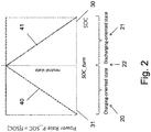
- Fig. 2 shows part of a method according to a second embodiment of the present invention.
- Fig. 2 an example function for a state-of-charge dependent power rate is shown.
- the SOC-turn point is a defined control point, at which the power rate changes its behavior from the maximum power rate to a state-of-charge dependent function, whereby the SOC-turn charging point does not need to be equal to the SOC_turn discharging point.
- SOC_turn the turning point of the state of charge SOC between charging and discharging mode denoted with SOC_turn is fixed in a well defined power rating scheme.
- SOC ⁇ SOC_turn the battery is in a charging-oriented state and within the range SOC > SOC_turn the battery is in a discharging oriented state.
- SOC_turn the battery is neutral.
- the SOC_turn value is denoted with reference sign 22
- the charging-oriented state is denoted with reference sign 20
- the discharging-oriented state is denoted with reference sign 21.
- the power rate P_SOC 31 as the function of the state of charge SOC rate 30 is shown in Fig. 2 .
- a maximum charging power 30 may be applied from a state of charge SOC 30 from 0% till the state of charge turning point SOC_turn and a linearly decreasing maximum charging power from the maximum of the charging power rate to 0 between the state of charge turning point SOC_turn 22 and the 100% state of charge SOC 30.
- This curve is denoted with reference sign 41.
- the linearly decreasing maximum charging power is assigned to the discharging-oriented state 21.
- the maximum discharging power rate 40 is linearly increasing from 0% state of charge SOC 30 until the state of charge turning point SOC_turn 22 up to the maximum discharging power rate. From the state of charge turning point SOC_turn 22 till the 100% state of charge SOC 30 the discharging power rate is applicable at its maximum. This curve is denoted with reference sign 40.
- the power rate equals the maximum charging power rate and has a linearly increasing discharging power rate P ⁇ max ⁇ t wherein in the discharging-oriented state 21 the maximum charging power is linearly decreasing whereas the discharging power rate is the maximum discharging power rate.
- f - and f + may be defined with regard to the underlying system, e.g. the following rules may be applied:
- charging-oriented state neutral state and discharging-oriented state
- neutral state discharging-oriented state
- the energy storage entity 6 When SOC t > SO C turn ⁇ , the energy storage entity 6 is said to have entered discharging oriented state. In this state, the virtual maximum charging rate is less than the physical maximum charging rate, while the virtual maximum discharging rate equals the physical maximum discharging rate. Hence, it is easier to discharge the energy storage entity 6 but harder to charge it when it is in discharging-oriented state.
- the selection of f - and f + may be dependent on an operator's perspectives over the underlying power grid. These two functions may be fixed once an energy storage entity 6 is installed.
- Fig. 3 shows part of a method according to a third embodiment of the present invention.
- Fig. 3 a further example for a state of charge dependent power rate is shown.
- the charging oriented state 20 and the discharging oriented state 21 have an overlapping region 23 in which the discharging power rate 40 and the charging power rate 41 are at their respective maximums.
- the discharging power rate 40 increases linearly from a 0% state of charge SOC until 100% at the discharging turning point SOC_turn_discharging and has the respective maximum power rate between the turning point SOC_turn_discharging and SOC_turn_charging and further from the SOC_turn_charging point to a 100% state of charge SOC.
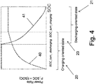
- Fig. 4 shows part of a method according to a fourth embodiment of the present invention.
- FIG. 4 another example for a state of charge dependent power rate function is shown. Similar to Fig. 3 the discharging turning point SOC_turn_discharging and the charging turning point SOC_turn_charging are different from each other.
- the power rate discharging curve 40 increases non-linearly until a maximum reached at the charging turning point SOC_turn_charging. However, this maximum is below the maximum of the charging power rate.
- the power rate discharging curve 40 and the charging power rate 41 have only one point of intersection which is in the overlapping region 23 of the charging-oriented state 20 and the discharging oriented state 21 and which is below the maxima of the charging power rate and of the discharging power rate.
- Fig. 5 shows a diagram representing battery cycles versus battery energy capacity for different power rates of a method according to a fifth embodiment of the present invention.
- Fig. 5 the interplay between power rate at charging and discharging mode and its relation to the available storage capacity of a battery is shown.
- the different curves 51-54 show cumulated battery cycles over a battery energy capacity.
- the curves 51 and 52 are based on a conventional charging and discharging scheme whereas the curves 53 and 54 use a charging/discharging scheme with a SOC_turn value of 50% according to Fig. 2 .
- the curves 51 and 53 have a maximum power rate of 2,5 kW and the curves 52 and 54 are rated at a maximum power rate of 5 kW.
- the curve 53 is below curve 51 and curve 54 is below curve 52. Therefore the respective cumulated battery cycles are higher for the conventional charging/discharging scheme compared with the embodiment according to the present invention.
- Fig. 6 shows a diagram representing battery stress time versus battery energy capacity of a method according to a sixth embodiment of the present invention for different power rates.
- Fig. 6 the cumulated battery stress time in minutes is shown dependent of the battery energy capacity.
- the curves 51-54 correspond to those in Fig. 5 .
- the cumulated battery stress time in minutes is significantly higher for the conventional charging/discharging schemes represented by curves 51 and 52 than those according to the embodiment of the present invention, represented by the curves 53 and 54.
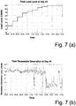
- Fig. 7a-7c show typical diagrams for a load profile, a daytime renewable generation level and contract power over daytime.
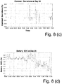
- Fig. 8a-8d show contract deviations and state-of-charge changes for different schemes according to a further embodiment of a method according to the present invention.
- Fig. 7a-c show a load profile, renewable generation levels, and 15-minute contracts for a particular day, for the time interval of 06:00 to 17:00 are shown.
- Fig. 8 shows the contract deviations and the change of the state-of-charge SOC of the energy storage entity 6 using a conventional management scheme and using a dynamic management scheme according to an embodiment of the present invention respectively.
- Fig. 9a-9d show performance comparisons between a conventional method and a method according to an embodiment of the present invention.
- the local power grid segment is managed by the independent service operator ISO who owns the battery 6, the small-scale wind turbine 7, e.g. several solar panels, this ISO serve electricity to a small number of households 3 and a small commercial building via purchasing contract-based electricity from distribution service operators DSO as well as local generations.
- ISO independent service operator
- DSO distribution service operators
- the hourly load level are generated based on California summer residential and commercial load profiles as provided in R.E. Brown and J.G. Koomey, "Electricity use in California: Past trends and present usage patterns", 2002, available: http://enduse.lbl.gov/Projects/CAdata.html .
- the electric vehicle (EV) charging and parking lot shown in Fig. 2 is disregarded in the following.
- the installed solar generation capacity is set to 10 kW and the installed wind generation capacity to 15 kW.
- the per-minute renewable generation data are obtained here from National Renewable Energy Laboratory (NREL), see: http://www.nrel.gov for the entire July of 2012 and then scaled to the underlying system specifications.
- the installed energy storage entity 6 is rated at 0,42 kWh/2,5 kW. Such a rating may be randomly selected but significantly under-provisioned value.
- the ISO renews the electricity contracts with the DSO by the end of every 15 minutes. It is calculated by the predicted total load level minus the predicted total renewable generation for the next 15 minutes. Since the energy storage entity 6 is very small, its effects on the contracts are neglected. In addition it is assumed the predictions on load and renewable generations are always accurate and the loads are constant over each hour.
- P dso (t) is the committed power flow between ISO and DSO to be determined
- P con (t) is the contract power value
- L(t) is the current total ISO load level
- Pren(t) is the total local renewable generation level at ISO
- Pess(t) is the power flow required from the energy storage entity 6 (P ess (t) takes positive values while the energy storage entity 6 is delivering power and negative values while the energy storage entity 6 is absorbing power).
- the energy storage entity 6 may be configured to respond only to contract deviations with magnitude higher than a dead-band value, say, 4%. However, the energy storage entity 6 is to balance every deviation.
- Total energy storage entity 6 stress time ⁇ t s In our simulation the energy storage entity 6 is under stress, when its SOC is greater than 95% or less than 5%. t s is calculated by counting the number of minutes that the energy storage entity 6 is under stress over the total simulation time.
- e oc value defined in the formula measures how much the ISO violates its contracts with DSO by consuming more power than expected. It is worth nothing that e oc is measured instead of total contract deviations over time because the penalty for over-commissions may be significantly higher than the other way round.
- Fig. 9a and Fig. 9b compare the e oc values for the conventional scheme against the dynamic scheme under different energy storage entity 6 characteristics. It can be seen that for either schemes, e oc decreases as the energy storage entity 6 takes higher E act or higher P stor . However, higher power rating has stronger impacts on reducing e oc values than higher storage rating under the system.
- the conventional scheme exhibits stronger effects in reducing the cumulated e oc value, or, in other words, has stronger effects on balancing the renewable generations, than the dynamic scheme.
- the difference slowly converges to zero as we increase the energy storage entity storage and power capacities.
- Fig. 9c and Fig. 9d show that the dynamic scheme generates significantly less ⁇ t s than the conventional scheme. The difference also converges to zero due to the fact that if a large enough energy storage entity 6 is installed, it is possible that the SOC of the energy storage entity 6 never falls outside the "safe boundaries". Besides, it can be observed that ⁇ t s increases as the energy storage entity 6 takes larger power capacities, which makes it easier for the energy storage entity 6 to get depleted or full. Similarly, ⁇ t s decreases as the energy storage entity 6 takes larger storage capacities.
- the present invention enables power rate control for charging and discharging mode with a defined deterministic function of system parameters in time distinct for charging and discharging mode.
- the present invention enables further power rate control as function of the state of charge and time, distinct for charging and discharging modes as well as with a fixed state of charge turn point, distinct for charging and discharging modes, defined by individual, possibly different, parameter pairs of the maximum state of charge power rate and the state of charge turn point for the power rate.
- the present invention increases the lifetime of battery-based energy storages in particular by a reduction of battery cycle numbers and by reduction of operation in battery stress mode.
- the present invention is suitable in particular under the distributed energy generation in the distribution grids, where a local generation penetration is increasing to a comparable level of distributed small-scaled loads and may be considered in isolated as well as grid-connected modes.
- the present invention is in particular applicable respectively can be used in sub-grids of hierarchical energy networks, in micro grids, for building energy systems, preferably home energy systems or in other words the present invention can be used or is applicable as storage system for resource handling on fluctuating resources, e.g. generation/sources, loads and/or a combination of generation and load.
- fluctuating resources e.g. generation/sources, loads and/or a combination of generation and load.
- the present invention enables - depending on the system size and characteristics in load and renewable - preferably a compromise of the battery operation costs against the system overall costs, i.e. for example contract violation costs versus battery size. This might depend on the economic constrains and possible other load balancing schemes in the same local power grid segment.
Landscapes
- Engineering & Computer Science (AREA)
- Power Engineering (AREA)
- Supply And Distribution Of Alternating Current (AREA)
- Charge And Discharge Circuits For Batteries Or The Like (AREA)
Claims (11)
- Ein Verfahren zum Betreiben einer Energiespeicherentität (6), vorzugsweise einer batteriebasierten Energiespeicherentität (6), wobei die Energiespeicherentität (6) verbunden ist mit zumindest einer Energiesenke (7, 8) und zumindest einer Energiequelle (9), wobei Energiefluktuationen Fluktuationen bei der Energieerzeugung der Energiequelle (9) und/oder der Energiesenke umfassen und/oder Ungleichgewichte zwischen Energiesenke (7, 8) und Energieerzeugung (9) zumindest teilweise durch die Energiespeicherentität (6) ausgeglichen werden,
wobei
zum Ausgleichen Lade- und/oder Entladeleistungsraten der Energiespeicherentität (6) gesteuert werden gemäß einer Steuerungsfunktion, die von zumindest einem Betriebsparameter abhängt, umfassend den Ladungszustand (SOC),
wobei zumindest drei Betriebszustände bereitgestellt werden durch die Energiespeicherentität (6), umfassend einen ladungsorientierten Zustand (20), einen entladungsorientierten Zustand (21) und einen neutralen Zustand (22, 23),
wobei
der ladungsorientierte Zustand (20) so definiert ist, dass die kontrollierte Entladeleistungsrate (40) unterhalb der maximalen Entladungsleistungsrate ist und wobei die kontrollierte Ladeleistungsrate (41) gleich der maximalen Ladeleistungsrate ist, der entladungsorientierte Zustand (21) so definiert ist, dass die kontrollierte Ladeleistungsrate (41) unterhalb der maximalen Ladeleistungsrate ist und wobei die kontrollierte Entladeleistungsrate (40) gleich der maximalen Entladeleistungsrate ist, dadurch gekennzeichnet, dass
der neutrale Zustand (22, 23) durch einen einzelnen SOC-Wendepunkt repräsentiert ist, wobei der SOC-Wendepunkt definiert ist als ein Kontrollpunkt, an dem die Leistungsrate ihr Verhalten wechselt von der maximalen Leistungsrate zu einer Ladezustandsfunktion basierend auf einer gewissen Energiespeicherinformation, wobei der einzelne SOC-Wendepunkt so definiert ist, dass die kontrollierte Entladeleistungsrate (40) der maximalen Entladeleistungsrate entspricht und die kontrollierte Ladeleistungsrate (41) der maximalen Ladeleistungsrate entspricht, oder der neutrale Zustand (22, 23) repräsentiert ist durch einen Überlappungsbereich des ladungsorientierten Zustandes und des entladungsorientierten Zustandes, wobei der Überlappungsbereich definiert ist durch SOC-Wendepunkte des ladungs- und entladungsorientierten Zustandes,
wobei die ladungs- und entladungsorientierten SOC-Wendepunkte sich voneinander unterscheiden, Perioden definiert werden und die SOC-Wendepunkte ausgewählt werden gemäß der Nutzung der Energiespeicherentität während der nächsten Betriebsperiode, und wobei die Energiespeicherentität so gesteuert wird, dass der neutrale Zustand als Betriebszustand für die Energiespeichereinheit bevorzugt wird. - Das Verfahren gemäß Anspruch 1, dadurch gekennzeichnet, dass ein Laden und/oder Entladen der Energiespeicherentität (6) so durchgeführt wird, dass die Energie, die in der Energiespeicherentität gespeichert ist, gleich oder größer als eine vorbestimmte Prozentzahl, vorzugsweise 50 %, der maximalen Speicherkapazität der Energiespeicherentität (6) im Mittel ist.
- Das Verfahren gemäß einem der Ansprüche 1-2, dadurch gekennzeichnet, dass die Steuerungsfunktion eine nichtlineare Funktion der Zeit und/oder des Ladungszustandes (SOC) der Energiespeicherentität (6) ist.
- Das Verfahren gemäß einem der Ansprüche 1-2, dadurch gekennzeichnet, dass die kontrollierte Entladeleistungsrate (40) linear ansteigt mit der Energiespeicherinformation, vorzugsweise dem Ladungszustand (SOC), in dem ladungsorientierten Zustand (20) und/oder die kontrollierte Ladeleistungsrate (41) linear abfällt mit der Energiespeicherinformation, vorzugsweise dem Ladungszustand (SOC) in dem entladungsorientierten Zustand (21).
- Das Verfahren gemäß einem der Ansprüche 1-4, dadurch gekennzeichnet, dass das Maximum der Ladeleistungsrate und das Maximum der Entladeleistungsrate sich voneinander unterscheiden.
- Das Verfahren gemäß einem der Ansprüche 1-5, dadurch gekennzeichnet, dass das Maximum der Leistungsraten und/oder der kontrollierten Lade- und/oder Entladeleistungsraten (40, 41) angepasst werden an den aktuellen Gesundheitszustand der Energiespeicherentität (6).
- Das Verfahren gemäß einem der Ansprüche 1-6, dadurch gekennzeichnet, dass die Leistungsflussbeschränkungen repräsentiert werden durch eine vorzugsweise zeitabhängige Kostenfunktion.
- Das Verfahren gemäß Anspruch 7, dadurch gekennzeichnet, dass die Kostenfunktion auf Vertragsdaten zwischen einem Netzbetreiber und einem Segmentbetreiber eines Energieverteilungssegments und/oder Netzes mit der Energiespeicherentität (6) basiert und/oder auf einem physikalischen Parameter basiert und/oder auf Betriebskosten der entsprechenden Netze und/oder Segmente.
- Das Verfahren gemäß einem der Ansprüche 1-8, dadurch gekennzeichnet, dass die Steuerungsfunktion als Parameter Leistungsflussbeschränkungen zwischen Energiequellen (9) und/oder Energiesenken (7, 8) und/oder zwischen verschiedenen Segmenten eines Leistungsnetzes umfasst.
- Das Verfahren gemäß Anspruch 9, dadurch gekennzeichnet, dass ein Leistungsfluss-Grenzbereich, vorzugsweise zeitabhängig, angewendet wird zum Überschreiten der Leistungsflussbeschränkungen im Mittel.
- Ein Energiespeichersystem zur Durchführung des Verfahrens gemäß einem der Ansprüche 1-10, mit einer Energiespeicherentität (6), vorzugsweise einer batteriebasierten Energiespeicherentität (6), wobei die Energiespeicherentität (6) verbunden ist mit zumindest einer Energiesenke (7, 8) und zumindest einer Energiequelle (9), wobei Energiefluktuationen Fluktuationen bei der Energieerzeugung der Energiequelle und/oder der Energiesenke (7, 8) umfassen und/oder Ungleichgewichte zwischen Energiesenke und Energieerzeugung (9) zumindest teilweise durch die Energiespeicherentität (6) ausgeglichen werden, wobei besagtes System Steuermittel (5) umfasst, die mit der Energiespeicherentität (6) verbunden, und die ausgebildet sind zum Kontrollieren von Lade- und/oder Entladeleistungsraten der Energiespeicherentität (6) gemäß einer Steuerungsfunktion, die von zumindest einem Betriebsparameter abhängt, umfassend den Ladungszustand (SOC),
wobei die Energiespeicherentität ausgebildet, um zumindest drei Betriebszustände bereitzustellen, umfassend einen ladungsorientierten Zustand (20), einen entladungsorientierten Zustand (21) und einen neutralen Zustand (22, 23) zum Ausgleichen, und wobei
der ladungsorientierte Zustand (20) so definiert ist, dass die kontrollierte Entladeleistungsrate (40) unterhalb der maximalen Entladeleistungsrate ist und wobei die kontrollierte Ladeleistungsrate (41) gleich der maximalen Ladeleistungsrate ist, und wobei
der entladungsorientierte Zustand (21) so definiert ist, dass die kontrollierte Ladeleistungsrate (41) unterhalb der maximalen Ladeleistungsrate ist und wobei die kontrollierte Entladeleistungsrate (40) gleich der maximalen Entladeleistungsrate ist, dadurch gekennzeichnet, dass
der neutrale Zustand (22, 23) durch einen einzelnen SOC-Wendepunkt repräsentiert ist, wobei der SOC-Wendepunkt definiert ist als ein Kontrollpunkt, an dem die Leistungsrate ihr Verhalten wechselt von der maximalen Leistungsrate zu einer Ladezustandsfunktion basierend auf einer gewissen Energiespeicherinformation, wobei der einzelne SOC-Wendepunkt so definiert ist, dass die kontrollierte Entladeleistungsrate (40) der maximalen Entladeleistungsrate entspricht und die kontrollierte Ladeleistungsrate (41) der maximalen Ladeleistungsrate entspricht,
oder der neutrale Zustand (22, 23) repräsentiert ist durch einen Überlappungsbereich des ladungsorientierten Zustandes und des entladungsorientierten Zustandes, wobei der Überlappungsbereich definiert ist durch SOC-Wendepunkte des ladungs- und entladungsorientierten Zustandes,
und wobei Betriebsperioden definiert werden und die SOC-Wendepunkte ausgewählt werden gemäß der Nutzung der Energiespeicherentität während der nächsten Betriebsperiode, und wobei die Energiespeicherentität so gesteuert wird, dass der neutrale Zustand als Betriebszustand für die Energiespeicherentität bevorzugt wird.
Priority Applications (1)
| Application Number | Priority Date | Filing Date | Title |
|---|---|---|---|
| EP13783865.2A EP2901536B1 (de) | 2012-09-28 | 2013-09-30 | Verfahren zum betreiben einer energiespeichereinheit und eines energiespeichersystems |
Applications Claiming Priority (4)
| Application Number | Priority Date | Filing Date | Title |
|---|---|---|---|
| EP12186642 | 2012-09-28 | ||
| EP12187263 | 2012-10-04 | ||
| PCT/EP2013/070362 WO2014049173A2 (en) | 2012-09-28 | 2013-09-30 | Method for operating an energy storage entity and an energy storage system |
| EP13783865.2A EP2901536B1 (de) | 2012-09-28 | 2013-09-30 | Verfahren zum betreiben einer energiespeichereinheit und eines energiespeichersystems |
Publications (2)
| Publication Number | Publication Date |
|---|---|
| EP2901536A2 EP2901536A2 (de) | 2015-08-05 |
| EP2901536B1 true EP2901536B1 (de) | 2019-01-09 |
Family
ID=49513904
Family Applications (1)
| Application Number | Title | Priority Date | Filing Date |
|---|---|---|---|
| EP13783865.2A Active EP2901536B1 (de) | 2012-09-28 | 2013-09-30 | Verfahren zum betreiben einer energiespeichereinheit und eines energiespeichersystems |
Country Status (2)
| Country | Link |
|---|---|
| EP (1) | EP2901536B1 (de) |
| WO (1) | WO2014049173A2 (de) |
Families Citing this family (10)
| Publication number | Priority date | Publication date | Assignee | Title |
|---|---|---|---|---|
| US20160091912A1 (en) * | 2014-09-30 | 2016-03-31 | Schneider Electric Usa Inc. | Demand-side grid-level load balancing aggregation system |
| CN104658292B (zh) * | 2015-02-15 | 2018-02-23 | 国网山东省电力公司沂南县供电公司 | 智能有序充电与车辆调度管理系统 |
| CN104779630B (zh) * | 2015-05-08 | 2017-07-11 | 武汉大学 | 一种平抑风电输出功率波动的混合储能系统容量配置方法 |
| EP3663723A1 (de) | 2018-12-04 | 2020-06-10 | Renishaw PLC | Codierervorrichtung |
| CN109697534A (zh) * | 2018-12-27 | 2019-04-30 | 国网能源研究院有限公司 | 一种跨国电力互联政策影响分析方法 |
| CN111555320B (zh) * | 2019-02-12 | 2025-12-23 | 周锡卫 | 一种优化配置的安全高效调频电池储能系统 |
| CN110336294B (zh) * | 2019-06-28 | 2021-10-15 | 国网河北省电力有限公司经济技术研究院 | 一种静态无功电源配置方法、终端设备及存储介质 |
| CN114583727B (zh) * | 2022-03-11 | 2026-03-03 | 华北电力大学 | 一种混合储能参与电网调频的充放电控制方法 |
| CN114825561B (zh) * | 2022-06-23 | 2022-09-27 | 中国人民解放军海军工程大学 | 超级电容组串主动均衡控制方法 |
| CN117791667B (zh) * | 2023-11-08 | 2024-09-27 | 国网甘肃省电力公司电力科学研究院 | 一种虚拟电厂的智能聚合协同控制方法 |
Family Cites Families (4)
| Publication number | Priority date | Publication date | Assignee | Title |
|---|---|---|---|---|
| FR2875963B1 (fr) * | 2004-09-29 | 2006-12-15 | Peugeot Citroen Automobiles Sa | Systeme de controle du fonctionnement de moyens de stockage d'energie electrique de moyens de motorisation hybride |
| KR101174891B1 (ko) * | 2010-06-01 | 2012-08-17 | 삼성에스디아이 주식회사 | 전력 저장 시스템 및 그 제어방법 |
| CN102598468A (zh) * | 2010-09-10 | 2012-07-18 | 松下电器产业株式会社 | 电力控制装置、电力控制方法及电力供给系统 |
| US8344550B2 (en) * | 2010-12-21 | 2013-01-01 | General Electric Company | Power conversion control with energy storage |
-
2013
- 2013-09-30 WO PCT/EP2013/070362 patent/WO2014049173A2/en not_active Ceased
- 2013-09-30 EP EP13783865.2A patent/EP2901536B1/de active Active
Non-Patent Citations (1)
| Title |
|---|
| None * |
Also Published As
| Publication number | Publication date |
|---|---|
| EP2901536A2 (de) | 2015-08-05 |
| WO2014049173A3 (en) | 2014-11-27 |
| WO2014049173A2 (en) | 2014-04-03 |
Similar Documents
| Publication | Publication Date | Title |
|---|---|---|
| Dufo-López et al. | Techno-economic analysis of grid-connected battery storage | |
| WO2014049173A2 (en) | Method for operating an energy storage entity and an energy storage system | |
| ur Rehman | RETRACTED: A robust vehicle to grid aggregation framework for electric vehicles charging cost minimization and for smart grid regulation | |
| Ranaweera et al. | Optimization of operational cost for a grid-supporting PV system with battery storage | |
| Saez-de-Ibarra et al. | Second life battery energy storage system for residential demand response service | |
| CN103078340B (zh) | 用于优化微网联络线功率的混合储能容量优化方法 | |
| US20140005852A1 (en) | Reduction of operational cost using energy storage management and demand response | |
| Barnes et al. | Placement of energy storage coordinated with smart PV inverters | |
| Bandpey et al. | Two-stage charging strategy of plug-in electric vehicles based on fuzzy control | |
| Xu et al. | Multi-objective chance-constrained optimal day-ahead scheduling considering BESS degradation | |
| Babacan et al. | Optimal allocation of battery energy storage systems in distribution networks considering high PV penetration | |
| Wang et al. | Active and reactive power support of MV distribution systems using battery energy storage | |
| Zhang et al. | Battery energy storage scheduling for optimal load variance minimization | |
| Fäßler et al. | Decentralized price-driven grid balancing via repurposed electric vehicle batteries | |
| Kim et al. | Field study on operational performance and economics of lithium-polymer and lead-acid battery systems for consumer load management | |
| Chua et al. | Peak reduction for commercial buildings using energy storage | |
| Yamashita et al. | Hierarchical model predictive control to coordinate a vehicle-to-grid system coupled to building microgrids | |
| JP6789020B2 (ja) | 蓄電池運用方法および蓄電池運用装置 | |
| Hazra et al. | Congestion relief using grid scale batteries | |
| Nousdilis et al. | Investigating the impact of decentralized energy storage systems in active low-voltage distribution networks | |
| Hwangbo et al. | Application of economic operation strategy on battery energy storage system at Jeju | |
| Luna et al. | Generation and demand scheduling for a grid-connected hybrid microgrid considering price-based incentives | |
| Sevilla et al. | Limiting transformer overload on distribution systems with high penetration of PV using energy storage systems | |
| Bessler et al. | Using flexibility information for energy demand optimization in the low voltage grid | |
| Sundgren | Optimization of a battery energy storage system: For utilization of peak shaving and fast frequency reserve |
Legal Events
| Date | Code | Title | Description |
|---|---|---|---|
| PUAI | Public reference made under article 153(3) epc to a published international application that has entered the european phase |
Free format text: ORIGINAL CODE: 0009012 |
|
| 17P | Request for examination filed |
Effective date: 20150306 |
|
| AK | Designated contracting states |
Kind code of ref document: A2 Designated state(s): AL AT BE BG CH CY CZ DE DK EE ES FI FR GB GR HR HU IE IS IT LI LT LU LV MC MK MT NL NO PL PT RO RS SE SI SK SM TR |
|
| AX | Request for extension of the european patent |
Extension state: BA ME |
|
| RIN1 | Information on inventor provided before grant (corrected) |
Inventor name: SCHUELKE, ANETT Inventor name: ETINSKI, MAJA Inventor name: WEN, HAOFU Inventor name: BODET, CEDRIC |
|
| DAX | Request for extension of the european patent (deleted) | ||
| STAA | Information on the status of an ep patent application or granted ep patent |
Free format text: STATUS: EXAMINATION IS IN PROGRESS |
|
| 17Q | First examination report despatched |
Effective date: 20171026 |
|
| RAP1 | Party data changed (applicant data changed or rights of an application transferred) |
Owner name: NEC LABORATORIES EUROPE GMBH |
|
| GRAP | Despatch of communication of intention to grant a patent |
Free format text: ORIGINAL CODE: EPIDOSNIGR1 |
|
| STAA | Information on the status of an ep patent application or granted ep patent |
Free format text: STATUS: GRANT OF PATENT IS INTENDED |
|
| RIC1 | Information provided on ipc code assigned before grant |
Ipc: H02J 3/24 20060101ALN20180115BHEP Ipc: H02J 3/00 20060101ALN20180115BHEP Ipc: H02J 3/32 20060101ALI20180115BHEP Ipc: H02J 3/38 20060101AFI20180115BHEP |
|
| INTG | Intention to grant announced |
Effective date: 20180206 |
|
| RIN1 | Information on inventor provided before grant (corrected) |
Inventor name: ETINSKI, MAJA Inventor name: WEN, HAOFU Inventor name: BODET, CEDRIC Inventor name: SCHUELKE, ANETT |
|
| GRAS | Grant fee paid |
Free format text: ORIGINAL CODE: EPIDOSNIGR3 |
|
| GRAJ | Information related to disapproval of communication of intention to grant by the applicant or resumption of examination proceedings by the epo deleted |
Free format text: ORIGINAL CODE: EPIDOSDIGR1 |
|
| GRAL | Information related to payment of fee for publishing/printing deleted |
Free format text: ORIGINAL CODE: EPIDOSDIGR3 |
|
| STAA | Information on the status of an ep patent application or granted ep patent |
Free format text: STATUS: EXAMINATION IS IN PROGRESS |
|
| REG | Reference to a national code |
Ref country code: DE Ref legal event code: R079 Ref document number: 602013049606 Country of ref document: DE Free format text: PREVIOUS MAIN CLASS: H02J0003320000 Ipc: H02J0003380000 |
|
| INTC | Intention to grant announced (deleted) | ||
| RAP1 | Party data changed (applicant data changed or rights of an application transferred) |
Owner name: NEC CORPORATION |
|
| GRAP | Despatch of communication of intention to grant a patent |
Free format text: ORIGINAL CODE: EPIDOSNIGR1 |
|
| STAA | Information on the status of an ep patent application or granted ep patent |
Free format text: STATUS: GRANT OF PATENT IS INTENDED |
|
| RIC1 | Information provided on ipc code assigned before grant |
Ipc: H02J 3/38 20060101AFI20180703BHEP Ipc: H02J 3/00 20060101ALN20180703BHEP Ipc: H02J 3/32 20060101ALI20180703BHEP Ipc: H02J 3/24 20060101ALN20180703BHEP |
|
| INTG | Intention to grant announced |
Effective date: 20180807 |
|
| GRAA | (expected) grant |
Free format text: ORIGINAL CODE: 0009210 |
|
| STAA | Information on the status of an ep patent application or granted ep patent |
Free format text: STATUS: THE PATENT HAS BEEN GRANTED |
|
| AK | Designated contracting states |
Kind code of ref document: B1 Designated state(s): AL AT BE BG CH CY CZ DE DK EE ES FI FR GB GR HR HU IE IS IT LI LT LU LV MC MK MT NL NO PL PT RO RS SE SI SK SM TR |
|
| REG | Reference to a national code |
Ref country code: GB Ref legal event code: FG4D |
|
| REG | Reference to a national code |
Ref country code: CH Ref legal event code: EP Ref country code: AT Ref legal event code: REF Ref document number: 1088534 Country of ref document: AT Kind code of ref document: T Effective date: 20190115 |
|
| REG | Reference to a national code |
Ref country code: IE Ref legal event code: FG4D |
|
| REG | Reference to a national code |
Ref country code: DE Ref legal event code: R096 Ref document number: 602013049606 Country of ref document: DE |
|
| REG | Reference to a national code |
Ref country code: NL Ref legal event code: MP Effective date: 20190109 |
|
| REG | Reference to a national code |
Ref country code: LT Ref legal event code: MG4D |
|
| PG25 | Lapsed in a contracting state [announced via postgrant information from national office to epo] |
Ref country code: NL Free format text: LAPSE BECAUSE OF FAILURE TO SUBMIT A TRANSLATION OF THE DESCRIPTION OR TO PAY THE FEE WITHIN THE PRESCRIBED TIME-LIMIT Effective date: 20190109 |
|
| REG | Reference to a national code |
Ref country code: AT Ref legal event code: MK05 Ref document number: 1088534 Country of ref document: AT Kind code of ref document: T Effective date: 20190109 |
|
| PG25 | Lapsed in a contracting state [announced via postgrant information from national office to epo] |
Ref country code: FI Free format text: LAPSE BECAUSE OF FAILURE TO SUBMIT A TRANSLATION OF THE DESCRIPTION OR TO PAY THE FEE WITHIN THE PRESCRIBED TIME-LIMIT Effective date: 20190109 Ref country code: NO Free format text: LAPSE BECAUSE OF FAILURE TO SUBMIT A TRANSLATION OF THE DESCRIPTION OR TO PAY THE FEE WITHIN THE PRESCRIBED TIME-LIMIT Effective date: 20190409 Ref country code: LT Free format text: LAPSE BECAUSE OF FAILURE TO SUBMIT A TRANSLATION OF THE DESCRIPTION OR TO PAY THE FEE WITHIN THE PRESCRIBED TIME-LIMIT Effective date: 20190109 Ref country code: PL Free format text: LAPSE BECAUSE OF FAILURE TO SUBMIT A TRANSLATION OF THE DESCRIPTION OR TO PAY THE FEE WITHIN THE PRESCRIBED TIME-LIMIT Effective date: 20190109 Ref country code: ES Free format text: LAPSE BECAUSE OF FAILURE TO SUBMIT A TRANSLATION OF THE DESCRIPTION OR TO PAY THE FEE WITHIN THE PRESCRIBED TIME-LIMIT Effective date: 20190109 Ref country code: PT Free format text: LAPSE BECAUSE OF FAILURE TO SUBMIT A TRANSLATION OF THE DESCRIPTION OR TO PAY THE FEE WITHIN THE PRESCRIBED TIME-LIMIT Effective date: 20190509 Ref country code: SE Free format text: LAPSE BECAUSE OF FAILURE TO SUBMIT A TRANSLATION OF THE DESCRIPTION OR TO PAY THE FEE WITHIN THE PRESCRIBED TIME-LIMIT Effective date: 20190109 |
|
| PG25 | Lapsed in a contracting state [announced via postgrant information from national office to epo] |
Ref country code: LV Free format text: LAPSE BECAUSE OF FAILURE TO SUBMIT A TRANSLATION OF THE DESCRIPTION OR TO PAY THE FEE WITHIN THE PRESCRIBED TIME-LIMIT Effective date: 20190109 Ref country code: RS Free format text: LAPSE BECAUSE OF FAILURE TO SUBMIT A TRANSLATION OF THE DESCRIPTION OR TO PAY THE FEE WITHIN THE PRESCRIBED TIME-LIMIT Effective date: 20190109 Ref country code: GR Free format text: LAPSE BECAUSE OF FAILURE TO SUBMIT A TRANSLATION OF THE DESCRIPTION OR TO PAY THE FEE WITHIN THE PRESCRIBED TIME-LIMIT Effective date: 20190410 Ref country code: BG Free format text: LAPSE BECAUSE OF FAILURE TO SUBMIT A TRANSLATION OF THE DESCRIPTION OR TO PAY THE FEE WITHIN THE PRESCRIBED TIME-LIMIT Effective date: 20190409 Ref country code: IS Free format text: LAPSE BECAUSE OF FAILURE TO SUBMIT A TRANSLATION OF THE DESCRIPTION OR TO PAY THE FEE WITHIN THE PRESCRIBED TIME-LIMIT Effective date: 20190509 Ref country code: HR Free format text: LAPSE BECAUSE OF FAILURE TO SUBMIT A TRANSLATION OF THE DESCRIPTION OR TO PAY THE FEE WITHIN THE PRESCRIBED TIME-LIMIT Effective date: 20190109 |
|
| REG | Reference to a national code |
Ref country code: DE Ref legal event code: R097 Ref document number: 602013049606 Country of ref document: DE |
|
| PG25 | Lapsed in a contracting state [announced via postgrant information from national office to epo] |
Ref country code: AT Free format text: LAPSE BECAUSE OF FAILURE TO SUBMIT A TRANSLATION OF THE DESCRIPTION OR TO PAY THE FEE WITHIN THE PRESCRIBED TIME-LIMIT Effective date: 20190109 Ref country code: DK Free format text: LAPSE BECAUSE OF FAILURE TO SUBMIT A TRANSLATION OF THE DESCRIPTION OR TO PAY THE FEE WITHIN THE PRESCRIBED TIME-LIMIT Effective date: 20190109 Ref country code: AL Free format text: LAPSE BECAUSE OF FAILURE TO SUBMIT A TRANSLATION OF THE DESCRIPTION OR TO PAY THE FEE WITHIN THE PRESCRIBED TIME-LIMIT Effective date: 20190109 Ref country code: SK Free format text: LAPSE BECAUSE OF FAILURE TO SUBMIT A TRANSLATION OF THE DESCRIPTION OR TO PAY THE FEE WITHIN THE PRESCRIBED TIME-LIMIT Effective date: 20190109 Ref country code: IT Free format text: LAPSE BECAUSE OF FAILURE TO SUBMIT A TRANSLATION OF THE DESCRIPTION OR TO PAY THE FEE WITHIN THE PRESCRIBED TIME-LIMIT Effective date: 20190109 Ref country code: RO Free format text: LAPSE BECAUSE OF FAILURE TO SUBMIT A TRANSLATION OF THE DESCRIPTION OR TO PAY THE FEE WITHIN THE PRESCRIBED TIME-LIMIT Effective date: 20190109 Ref country code: CZ Free format text: LAPSE BECAUSE OF FAILURE TO SUBMIT A TRANSLATION OF THE DESCRIPTION OR TO PAY THE FEE WITHIN THE PRESCRIBED TIME-LIMIT Effective date: 20190109 Ref country code: EE Free format text: LAPSE BECAUSE OF FAILURE TO SUBMIT A TRANSLATION OF THE DESCRIPTION OR TO PAY THE FEE WITHIN THE PRESCRIBED TIME-LIMIT Effective date: 20190109 |
|
| PLBE | No opposition filed within time limit |
Free format text: ORIGINAL CODE: 0009261 |
|
| STAA | Information on the status of an ep patent application or granted ep patent |
Free format text: STATUS: NO OPPOSITION FILED WITHIN TIME LIMIT |
|
| PG25 | Lapsed in a contracting state [announced via postgrant information from national office to epo] |
Ref country code: SM Free format text: LAPSE BECAUSE OF FAILURE TO SUBMIT A TRANSLATION OF THE DESCRIPTION OR TO PAY THE FEE WITHIN THE PRESCRIBED TIME-LIMIT Effective date: 20190109 |
|
| 26N | No opposition filed |
Effective date: 20191010 |
|
| PG25 | Lapsed in a contracting state [announced via postgrant information from national office to epo] |
Ref country code: SI Free format text: LAPSE BECAUSE OF FAILURE TO SUBMIT A TRANSLATION OF THE DESCRIPTION OR TO PAY THE FEE WITHIN THE PRESCRIBED TIME-LIMIT Effective date: 20190109 |
|
| PG25 | Lapsed in a contracting state [announced via postgrant information from national office to epo] |
Ref country code: TR Free format text: LAPSE BECAUSE OF FAILURE TO SUBMIT A TRANSLATION OF THE DESCRIPTION OR TO PAY THE FEE WITHIN THE PRESCRIBED TIME-LIMIT Effective date: 20190109 |
|
| PG25 | Lapsed in a contracting state [announced via postgrant information from national office to epo] |
Ref country code: MC Free format text: LAPSE BECAUSE OF FAILURE TO SUBMIT A TRANSLATION OF THE DESCRIPTION OR TO PAY THE FEE WITHIN THE PRESCRIBED TIME-LIMIT Effective date: 20190109 |
|
| REG | Reference to a national code |
Ref country code: CH Ref legal event code: PL |
|
| PG25 | Lapsed in a contracting state [announced via postgrant information from national office to epo] |
Ref country code: LU Free format text: LAPSE BECAUSE OF NON-PAYMENT OF DUE FEES Effective date: 20190930 Ref country code: IE Free format text: LAPSE BECAUSE OF NON-PAYMENT OF DUE FEES Effective date: 20190930 Ref country code: CH Free format text: LAPSE BECAUSE OF NON-PAYMENT OF DUE FEES Effective date: 20190930 Ref country code: LI Free format text: LAPSE BECAUSE OF NON-PAYMENT OF DUE FEES Effective date: 20190930 |
|
| REG | Reference to a national code |
Ref country code: BE Ref legal event code: MM Effective date: 20190930 |
|
| PG25 | Lapsed in a contracting state [announced via postgrant information from national office to epo] |
Ref country code: BE Free format text: LAPSE BECAUSE OF NON-PAYMENT OF DUE FEES Effective date: 20190930 |
|
| GBPC | Gb: european patent ceased through non-payment of renewal fee |
Effective date: 20190930 |
|
| PG25 | Lapsed in a contracting state [announced via postgrant information from national office to epo] |
Ref country code: FR Free format text: LAPSE BECAUSE OF NON-PAYMENT OF DUE FEES Effective date: 20190930 Ref country code: GB Free format text: LAPSE BECAUSE OF NON-PAYMENT OF DUE FEES Effective date: 20190930 |
|
| PG25 | Lapsed in a contracting state [announced via postgrant information from national office to epo] |
Ref country code: CY Free format text: LAPSE BECAUSE OF FAILURE TO SUBMIT A TRANSLATION OF THE DESCRIPTION OR TO PAY THE FEE WITHIN THE PRESCRIBED TIME-LIMIT Effective date: 20190109 |
|
| PG25 | Lapsed in a contracting state [announced via postgrant information from national office to epo] |
Ref country code: MT Free format text: LAPSE BECAUSE OF FAILURE TO SUBMIT A TRANSLATION OF THE DESCRIPTION OR TO PAY THE FEE WITHIN THE PRESCRIBED TIME-LIMIT Effective date: 20190109 Ref country code: HU Free format text: LAPSE BECAUSE OF FAILURE TO SUBMIT A TRANSLATION OF THE DESCRIPTION OR TO PAY THE FEE WITHIN THE PRESCRIBED TIME-LIMIT; INVALID AB INITIO Effective date: 20130930 |
|
| PG25 | Lapsed in a contracting state [announced via postgrant information from national office to epo] |
Ref country code: MK Free format text: LAPSE BECAUSE OF FAILURE TO SUBMIT A TRANSLATION OF THE DESCRIPTION OR TO PAY THE FEE WITHIN THE PRESCRIBED TIME-LIMIT Effective date: 20190109 |
|
| PGFP | Annual fee paid to national office [announced via postgrant information from national office to epo] |
Ref country code: DE Payment date: 20250919 Year of fee payment: 13 |