EP2901503B1 - Carrier element and module - Google Patents
Carrier element and module Download PDFInfo
- Publication number
- EP2901503B1 EP2901503B1 EP14711704.8A EP14711704A EP2901503B1 EP 2901503 B1 EP2901503 B1 EP 2901503B1 EP 14711704 A EP14711704 A EP 14711704A EP 2901503 B1 EP2901503 B1 EP 2901503B1
- Authority
- EP
- European Patent Office
- Prior art keywords
- carrier element
- plate
- element according
- heat source
- heat sink
- Prior art date
- Legal status (The legal status is an assumption and is not a legal conclusion. Google has not performed a legal analysis and makes no representation as to the accuracy of the status listed.)
- Not-in-force
Links
Images


Classifications
-
- H—ELECTRICITY
- H10—SEMICONDUCTOR DEVICES; ELECTRIC SOLID-STATE DEVICES NOT OTHERWISE PROVIDED FOR
- H10N—ELECTRIC SOLID-STATE DEVICES NOT OTHERWISE PROVIDED FOR
- H10N10/00—Thermoelectric devices comprising a junction of dissimilar materials, i.e. devices exhibiting Seebeck or Peltier effects
- H10N10/10—Thermoelectric devices comprising a junction of dissimilar materials, i.e. devices exhibiting Seebeck or Peltier effects operating with only the Peltier or Seebeck effects
- H10N10/17—Thermoelectric devices comprising a junction of dissimilar materials, i.e. devices exhibiting Seebeck or Peltier effects operating with only the Peltier or Seebeck effects characterised by the structure or configuration of the cell or thermocouple forming the device
Definitions
- the invention relates to a carrier element comprising a connection to a heat source and a connection to a heat sink as well as a thermoelectric thin-film element arranged on the carrier element between the connection to the heat source and the connection to the heat sink. Moreover, the invention relates to a module with a plurality of carrier elements.
- thermoelectric element operated as a generator. It is preferable to use differently doped semiconductor materials for this purpose, which can significantly increase the efficiency compared to thermocouples with two different metals joined together at one end. Common semiconductor materials are Bi 2 Te 3 , PbTe, SiGe, BiSb and FeSi 2 . In order to generate sufficiently high voltages, a plurality of thermocouples is usually electrically connected in series in a thermoelectric element.
- thermoelectric elements consist of several blocks of thermoelectrically active semiconductor material, which are alternately connected at the top and bottom by metal bridges electrically conductive.
- the metal bridges at the same time form the thermal contact surfaces and are insulated by a ceramic plate lying on top.
- thermoelectric thin-film elements are known from the prior art:
- thermoelectric thin film element having a support structure on which a plurality of thermo legs of a first conductive material and a plurality of thermo legs of a second conductive material are applied, wherein the first and second conductive material have a different conductivity and the thermo legs are electrically coupled to each other each two thermo legs form a thermocouple, wherein all thermo legs of the first and second conductive material are arranged side by side on the support structure.
- the cold side of the thermoelectric thin film element is located on one side of the electrically conductive first and second materials and the hot side on the opposite side of the electrically conductive first and second materials.
- thermoelectric thin-film element which has a flexible substrate material, are applied to the thin-film thermocouples.
- the thin-film thermocouples are formed of a combination of materials of two different materials, with the first and second materials set up and so on thermally coupled with each other to form a thermocouple together.
- the two materials are printed on the flexible film or deposited by conventional deposition.
- the coupled strips form a series connection of several thermocouples on a small area.
- thermocouples leads to a high output voltage of the thermocouple.
- the electrical coupling structures on one side of the thermoelectric thin-film element form its hot side
- the coupling structures on the opposite side of the thermoelectric thin-film element form its cold side, wherein the hot side is connected to a coupling element to a heat source and the cold side to a heat sink.
- thermoelectric thin-film element with a hot and a cold side
- the flexible thin-film element is clamped on the hot side between two profiles of a coupling element and on the cold side between two profiles of a heat sink.
- the heat sink is formed in the illustrated embodiment of the clamping profiles on which are arranged away from the clamping profiles extending cooling fins.
- thermoelectrically active materials are brittle and can only be loaded mechanically under pressure. Tensile and shear stress therefore do not lead to plastic deformation, but to breakage of the thermoelectrically active materials.
- thermoelectrically active materials of conventional thermoelectric elements despite different dimensions of the heat source and the If possible, heat sink only to pressure load, the connection of the ceramic plate on the hot side to the heat source sliding.
- the desired in the interest of a high efficiency of the thermoelectric element low thermal resistance between the heat source and the ceramic plate basically requires a very high contact pressure, which, however, prohibits due to the necessary to compensate for different expansions slide bearing. In order to find an optimal compromise in this respect, a uniform frictional connection is required over the entire surface of the slide-mounted ceramic plate, which can be realized only with extremely large, previously not automatable production cost.
- thermoelectric module that extends in a longitudinal direction, with an outer tube and an inner tube disposed within the outer tube and an intermediate space arranged therebetween.
- a first strip-shaped structure and a second strip-shaped structure are provided, wherein the first strip-like structure, starting from a first connection to the inner tube and the second strip-like structure, starting from a second connection to the outer tube in opposite directions in a circumferential direction extend the tubes or their longitudinal direction.
- the strip-shaped structures overlap partially in the circumferential direction or in the longitudinal direction, wherein a pair of semiconductor elements is arranged in the region of the overlap between the first and the second strip-shaped structure.
- the outer tube and the inner tube are arranged to one another such that a thermal expansion of the module is compensated primarily by a relative movement of the outer tube relative to the inner tube.
- the strip-shaped structures are arranged resiliently.
- the present invention seeks to propose a support member having a thermoelectric thin-film element disposed on the support member, which is particularly suitable for the attachment of the thin-film element and the harmful with good thermal connection to a heat source and heat sink tensile and Avoiding shear stresses in the thermoelectric thin-film element, in particular in the thermoelectrically active material.
- thermoelectrically active material which is sensitive to shearing loads is arranged in the remaining areas and is thus not exposed to any shear loads.
- the inventively provided compensation section allows a material connection of the carrier element to the heat source and the heat sink.
- a cohesive connection eliminates the need to build large pressure forces between the heat source or heat sink and the connection of the support member to the heat source or heat sink to achieve a low thermal resistance.
- the cohesive connection allows greater manufacturing tolerances of both the carrier element and the heat source or heat sink. Any manufacturing tolerances can be compensated for example by an adhesive or a solder for the production of the cohesive connection.
- the carrier element has a plate for applying the thermoelectric thin-film element.
- the flat surface is particularly suitable for the attachment of the thermoelectric thin-film element.
- the compensation section can be introduced directly into a relatively thin plate, in particular by embossing. For the preferably cohesive connection of the carrier element to the heat source and the heat sink connecting elements are arranged on the plate.
- each compensation section preferably has a linear-elastic behavior.
- the compensation section may have embossed protrusions and / or depressions to compensate for the stresses due to the different expansions of the heat source and heat sink.
- the compensation section preferably has a knobbed structure with a two-dimensional arrangement of Elevations and depressions. Such a nub structure allows compensation movements of the forces occurring in the compensation section in all spatial directions.
- the elastic compensation section can also be designed in the manner of a pipe compensator as an elastic bellows - also known as bellows.
- Each bellows may be provided with at least one, preferably a plurality of slots which extend transversely to the course of the folds of the bellows. If the folds of the bellows are perpendicular to the main direction of expansion of the heat source, expansions of the heat source with respect to the heat sink perpendicular to the main extension direction are compensated by the slots. Similar to the compensated portion provided with nub structure and the slotted bellows allows compensating movements of the forces occurring in the compensation section in all spatial directions.
- the elastic compensation portion may be made of the same material as the remaining portions of the support member.
- a material for the carrier element and the embossed elastic compensation section metals are used, for example, which can withstand aggressive media and high temperatures well.
- the elastic compensation section can deviate from the other areas of the carrier element also made of soft material, such as technical fabrics or elastomers.
- thermoelectric thin-film element has a substrate and thermoelectrically active material applied to the substrate.
- the thermoelectrically active material has a layer thickness of not more than 150 ⁇ m.
- the substrate is electrically insulating in order to connect mutually separate regions of thermoelectrically active material alternately on the hot and cold side of the thin-film element by metallized regions deposited on the substrate.
- the material of the substrate has a low thermal conductivity.
- the regions of thermoelectrically active material are preferably connected in series.
- the substrate may be flexible, for example formed as a polyimide film.
- the film-formed substrate is preferably strip-shaped with the hot and cold sides on opposite longitudinal sides of the strip.
- the flexible film can also be arranged and fastened to the compensator section completely or partially overlapping on the carrier element. When arranging and fixing the film on the carrier element, however, care must be taken that no thermoelectrically active material is located in the region above the compensator section.
- the substrate may also consist of a rigid material.
- each compensator section is located in a region of the carrier element which does not overlap with the substrate. Otherwise, the elastic and / or flexible behavior of the Kompensatorabitess would be prevented by the rigid material of the substrate.
- thermoelectric thin-film element is integrally bonded to a particular flat surface of the carrier element, for example by gluing or soldering.
- the back side of the substrate to be soldered can be metallized.
- thermoelectric thin film element with a flexible substrate is mounted on the supporting element configured as a plate
- the plate and the substrate in the overlapping sections may have mutually aligned slots which compensate for stresses occurring in the overlapping sections.
- the slits in the plate and the substrate run for this purpose, in particular perpendicular to the main extension direction of the heat source. If the compensation section is designed as a bellows, the slots run perpendicular to its folds.
- the connecting elements are arranged on the plate, which extend at an angle, in particular perpendicular to the plane of the plate. If the connecting elements are designed as tabs, they can be made by bending the plate on opposite longitudinal sides.
- the connecting elements are preferably designed sleeve-shaped. The size of the contact surface between the sleeve and the tube leads to a very good thermal connection. If the sleeve passes through the plate, the tube of the heat sink or heat source can be passed through the sleeve.
- thermoelectric thin-film element In order to achieve a uniform heat coupling or decoupling, a plurality of connecting elements are arranged uniformly along the hot or cold side of the thermoelectric thin-film element. If only one connection element is arranged on the hot side and one connection element on the cold side of the thermoelectric thin-section element, the longitudinal extension of the connection element in the plane of the plate corresponds approximately to the longitudinal extent of the thermoelectric thin-layer element along the hot and cold sides.
- the support element may be provided in partial areas with a functional layer having a higher thermal conductivity than the support element.
- the support element consists for example of stainless steel and the functional layer of copper.
- the functional layer is applied in particular in the region of the connection to the heat source or heat sink and in the overlap region between the support element and the thermoelectric thin-film element.
- the functional layer is interrupted in order to avoid loss heat flows between the cold and hot side of the thermoelectric element, which is applied with its substrate on the functional layer.
- the interruption of the functional layer can be designed as a gap.
- a further decoupling of the heat source from the heat sink can be achieved by dividing the support element, in particular its plate, by at least one slot, wherein a first part of the plate is connected to the heat source on one side of the slot second part of the plate on the opposite side of the slot with the heat sink in thermally conductive connection.
- the first and second part of the plate can be connected to each other by at least one, preferably a plurality of bridges bridging the slot, which are narrow relative to the longitudinal extension of the slot.
- the narrow in relation to the slot length webs flow only low parasitic heat losses from the hot to the cold side. If a functional layer is provided on the carrier element, this is interrupted in the region of the webs.
- the web extension may be formed on the first and / or second part of the plate as a compensation section.
- the material thickness and / or the material properties of the web in the region of the attachment can be changed relative to the other regions of the carrier element.
- the thermoelectrically active material of the thin film element is located exclusively in an area above the slot with respect to the plate surface, the metallized areas of the thin film element alternately thermally conductive on its hot side with the first part on its cold side with the second part of the plate or functional layer are connected.
- the web projections acting as compensation sections define on both sides of the thermoelectrically active material in each case a bending line for receiving the different expansions of the heat source and heat sink.
- the bend lines extend along the transition regions of the thermoelectrically active material to the metallized contact regions on the flexible substrate.
- the substrate can follow a rotational movement about the bending line of the carrier element, without stressing thermoelectrically active material by shear forces.
- the slot has a slot width of 4 mm and the thermoelectrically active material has an extension of 2 mm in the direction of the slot width, a transitional area of 1 mm in each case arises on both sides with a central arrangement of the thermoelectrically active material in the slot. In this transition area, the bending line runs.
- the heat sink and / or heat source comprises at least one tube for a heat transfer medium, to which the carrier element is connected. This allows, for example, the waste heat from a Use heating circuit in one or more thermoelectric thin-film elements.
- thermoelectric thin-film elements As the tubes of the heat source or heat sink and the sleeve-shaped connecting elements receiving them extend perpendicularly to the plate of the carrier element, the heat flow in the thermoelectric thin-film elements runs transversely to the flow direction of the heat carrier in each tube. As a result, a temperature drop along the thermoelectric thin-film element is avoided, resulting in a significant increase in performance.
- an arrangement of the carrier elements transversely to the longitudinal extent of the heat source and heat sink allows the proper functioning of the compensation section in the web approach.
- thermoelectric thin-film elements can be combined to form a module.
- the thin-film elements mounted on the plurality of carrier elements can be partially electrically connected in series or in parallel.
- the plate of the support member is annular and divided by a slot in two concentric circular rings.
- a shaped support member allows connection to an elongated, in particular tubular heat source and heat sink, both of which extend perpendicular to the annular plate.
- the connecting elements for connection to the heat source and heat sink also extend perpendicular to the plane of the plate.
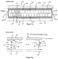
- FIG. 1a shows a sectional side view of a carrier element according to the invention (10) on which a thermoelectric thin-film element (20) is arranged.
- the carrier element (10) is designed as a sheet metal part, for example Made of stainless steel sheet and consists of an elongated rectangular plate (11) which is provided at its longitudinal edges with connecting elements (13 a, b), which in the embodiment according to FIG. 1 are designed as tabs. The tabs may be bent portions of the sheet metal part.
- the lower connecting element (13a) serves for connection to a heat sink (30) and the upper connecting element (13b) for connection to a heat source (40).
- the heat sink (30) and the heat source (40) each comprise a tube (31, 41) with an elongate, rectangular cross-section for a heat transfer medium, which flows through the tubes (31, 41) transversely to the plane of the plate.
- the tube cross-section extends over the entire length of the strip-shaped thermoelectric thin-film element (20) applied to the carrier element (10).
- the designed as a flap upper connecting element (13b) is cohesively with the underside of the tube (41) and designed as a flap lower connecting element (13a) is firmly bonded to the top of the tube (31).
- the material connection is effected in particular by a solder.
- the plate (11) of the carrier element (10) is divided centrally into a first and a second part (11a, 11b) by a slot (14) running parallel to its longitudinal edges (12), the first part (11a) of the plate (11) 11) with the heat source (40) and the second parts (11b) of the plate on the opposite longitudinal side of the slot (14) with the heat sink (30) is in thermally conductive connection.
- the first part (11a) and the second part (11b) of the plate (11) are interconnected by a web (15) bridging the slot (14).
- the web projections (15a) on the first part (11a) and the web extensions (15b) on the second part (11b) of the plate (11) define two bending lines as compensation sections (16) extending parallel to the longitudinal edges (12) of the plate (11).
- the compensation sections (16) of the carrier element (10) thus formed compensate for different thermo-mechanical expansions of the heat source (40) and the heat sink (30).
- thermoelectric thin-film element (20) detects in the embodiment FIG. 1a, b a flexible, strip-shaped substrate (21), for example in the form of a polyimide film, on which the thermoelectrically active material (22) is applied in separate regions (23).
- the application can take place, for example, by way of sputtering deposition or other methods known per se for the deposition of layers.
- the separated regions (23) of thermoelectrically active material (22) are connected in alternation on a hot side (24) and a cold side (25) of the thermoelectric thin-film element (20) through metallized regions (26) to each other in a series connection.
- the hot and cold sides (24, 25) of the thermoelectric thin-film element run parallel to the longitudinal edges (12) of the plate (11) of the carrier element (10).
- the hot side (24) is thermally conductive with the connecting element (13b) for connection to the heat source (40) and the cold side (25) thermally conductively connected to the connecting element (13a) to the heat sink (30).
- the carrier element (10) is provided in partial regions with a functional layer (17) (hatched representation), which has a higher thermal conductivity than the carrier element (10).
- the functional layer consists in the embodiment of copper.
- the plate (11) of the carrier element (10) is provided in the region of the first and second parts (11a, 11b) of the plate (11) with the functional layer (17).
- the functional layer (17) is also applied to the surfaces of the connecting elements (13a, 13b) which come into contact with the tubes (31, 41) in order to achieve a good thermal connection to the heat sink (30) or heat source (14) ,
- the substrate In order to fasten the flexible substrate (21) of the thermoelectric thin-film element (20) on the functional layer (17) of the carrier element, the substrate is provided on its rear side facing the functional layer (17) with a coating, in particular metallization, which performs a soldering of the Thermoelectric thin-film element (20) on the provided with the functional layer (17) support element (10).
- thermoelectrically active material (22) do not extend over the entire slot width (14a) between the hot and cold sides (24, 25).
- the slot width is 4 mm, while the areas (23) with the thermoelectrically active material (22) extend only over a length of 2 mm.
- the thermoelectrically active material (22) arranged centrally above the slot (14) ensures that no thermoelectrically active material is located in the region of the bending lines defined by the web extensions (15a, 15b). Along these bending lines is only the flexible substrate (21), which is not affected by the bend.
- the carrier element (10) according to FIG. 1 works as follows:
- the tube (41) of the heat source (40) Upon heating the tube (41) of the heat source (40), the tube (41) expands relative to the tube (31) of the heat sink (30) primarily transverse to the surface of the plate (11), as in the right half of the picture of the FIG. 1 a is shown. Stresses due to the thermo-mechanical expansion between the heat source (40) and the heat sink (30) are introduced into the webs (15) of the carrier element (10) and cause in the web extensions (15a, 15b) a bending movement to the by the web projections (15a , 15b) defined bending lines, which run parallel to the longitudinal edges (12). Due to the bending around the bending lines lying in the plane of the plate, the expansions transversely to the plane of the plate can be completely compensated in the compensation sections (16).
- FIG. 2 shows an embodiment of a support element (10) on which a thermoelectric thin-film element (20) with a rigid substrate (27) is arranged.
- the carrier element (10) consisting of copper sheet is particularly suitable for high-temperature applications. It detects in accordance with the embodiment FIG. 1 a plate (11) divided into a first part (11a) and a second part (11b) by a slot (14), but with a significantly larger slot width (14a), on which the rigid substrate (27) of the thermoelectric thin-film element (11) 20) is attached heat-conducting, for example by soldering.
- the connecting elements (13a, 13b) for connection to the heat sink (30) or heat source (40) are also designed as tabs.
- the upper connecting element (13b) is connected via a compensation section (16) to the upper longitudinal edge (12) of the plate (11).
- the lower connecting element (13b) is connected via a compensation section (16) to the lower longitudinal edge (12) of the plate (11).
- the two compensation sections (16) do not overlap with the rigid substrate (27), but extend from the Longitudinal edges (12) of the plate (11) in the direction of the heat sink (30) and the heat source (40).
- the connecting elements (13a, 13b) designed as lugs are connected in a materially cohesive manner to the heat source or heat sink (30, 40), as in the exemplary embodiment FIG. 1 ,
- the compensation sections (16) are designed as an elastic bellows (18) which extends over the entire length of the carrier element (10).
- the compensation section (16) may comprise a two-dimensional sequence of protrusions (16a) and depressions (16b), as shown in FIG FIG. 3a is recognizable.
- a nub structure formed in this way allows compensation movements in all spatial directions.
- the carrier element (10) according to FIG. 2 works as follows:
- thermoelectric thin-film element (20) arranged on the plate (11) is not loaded.
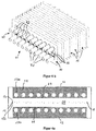
- the carrier element (10) according to FIG. 4a agrees in construction with the support element (10) FIG. 1a, b largely coincide, so that to avoid repetition on the local statements reference is made in full. Differences arise with regard to the structure of the heat sink and the heat source (30, 40) and the connection of the support element to the heat source and heat sink (30, 40).
- the heat sink (30) and the heat source (40) each comprise a tube bundle (32, 42).
- the tubes of a tube bundle (32, 42) extend parallel and at a distance from one another, wherein each tube of the tube bundle (32, 42) extends perpendicular to the plate plane of the carrier element (10).
- thermoelectric thin-film element (20) On the plate (11) of the carrier element (10) are on the hot and cold side (24, 25) of the thermoelectric thin-film element (20) corresponding to the number of tubes of the tube bundle (32, 42) formed as sleeves connecting elements (13a, 13b) arranged.
- the outer sheath of each tube is preferably cohesively connected, for example by means of a solder connection with one of the sleeves.
- the large-area connection of the carrier element (10) via the sleeves to the tubes of the heat sink or heat source (30, 40) increases the heat flux density and increases the efficiency of standing with the support member (10) in thermally conductive connection thermoelectric thin-film element (20).
- the carrier element (10) according to FIG. 4 a works as follows:
- the heat source (40) When heating the tubes of the tube bundle (42), the heat source (40) expands relative to the tubes of the tube bundle (32) of the heat sink (30) primarily transversely to the surface of the plate (11). Stresses due to the different expansions between the heat source (40) and the heat sink (30) are introduced into the webs (15) of the carrier element (10) and cause in the web extensions (15a, 15b) a bending movement to the by the web projections (15a , 15b) defined bending lines, which extend parallel to the longitudinal edges (12) of the plate (11). Due to the bending around the bending lines lying in the plane of the plate, the expansions transversely to the plane of the plate can be completely compensated in the compensation sections (16).
- FIG. 4b shows a module (50), the more identical support elements (10) after FIG. 4a comprises, wherein all support elements (10) in the same way, in the manner of a stack, to the tube bundles (32, 42) of the heat sink (30) or heat source (40) are connected.
- Each tube of the two tube bundles (32, 42) runs perpendicular to the plate plane of the carrier elements (20).
- the heat sink (30) or heat source (40) each comprises only a single circular cross-section tube (31, 41).
- the contour of the carrier element (10) is different from the previous embodiments, not rectangular, but oval.
- the connecting elements (13a, 13b) are according to the embodiment according to FIG. 4a designed as sleeves.
- the oval plate is also divided by a horizontally extending slot (14).
- the first part (11a) and the second part (11b) of the plate are connected to each other by the two outer, the slot bridging webs (15). Consistent with the other embodiments, the web extensions (15a, 15b) on the first and second parts (11a, 11b) of the plate (11) form the elastic compensation section (16) of the carrier element.
- the highly thermally conductive functional layer (17) is not provided in the region of the webs (15) and in the region of the slot (14).
- the functional layer is applied to the inner surface of the sleeves in order to improve the thermal connection to the surface of the heat source or heat sink (30, 40).
- a plurality of matching identical support elements (10) in a kind of stack on the tube of the heat sink (30) or the tube of the heat source (40) can be arranged one behind the other.
- the embodiment of the carrier element (10) according to FIG. 5b corresponds to the embodiment of the carrier element according to FIG. 4a with the difference that the heat source and the heat sink (30, 40) is not formed as a tube bundle (32, 42), but as a rectangular in cross-section tube (31, 41) extending over the full width of the in FIG. 5b not shown, thermoelectric thin-film element (20) with flexible substrate (21).
- the operation of the compensation section (16) corresponds to that according to the embodiments according to FIGS. 1 . 4 and 5 , so that reference is made to avoid repetition on the statements there.
- the carrier element (10) according to FIG. 5c is for the arrangement of two strip-shaped, in FIG. 5c not shown flexible thermoelectric thin-film elements (20) suitable. In the middle extends over the length of the carrier element (10) designed as an elongated rectangular sleeve connecting element (13a) for connection to the heat source (40) by a central, rectangular in cross section tube (41).
- the plate (11) of the carrier element is divided by a slot (14), wherein in each case a first part (11a) of the plate (11) on a longitudinal side of the slot (14 ) with the heat source (40) and in each case a second part (11b) of the plate (11) on the opposite side of each slot (14) with one of the two tubes (31) of the heat sink (30) in heat-conducting connection.
- the web projections (15a, 15b) represent the compensation sections (16) of the support element between the connection to the heat source (40) and the connection to the heat sinks (30).
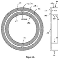
- FIGS. 6a . 6b show an embodiment of a support element (10) with an annular plate (11) on the ring a flexible thermoelectric thin-film element (20) is arranged.
- the annular plate (11) is divided by a circular slot (14) into two concentric circular rings (19a, 19b).
- the circular rings (19a, 19b) are at four offset by 90 degrees to each other arranged locations the slot (14) bridging by webs (15) connected to each other.
- a circumferential over the entire circumference connecting element (13a) for connection to a heat source (40) is arranged.
- a connecting element (13b) extending over the entire circumference is arranged for connection to a heat sink (30).
- the connecting elements (13a, 13b) formed as tabs extend at right angles to the plate surface.
- the functional layer (17) of highly thermally conductive material is mounted on the outwardly facing annular surface of the annuli (19a, 19b) which comes into contact with the thermoelectric thin film element. In order to avoid parasitic heat flows from the hot to the cold side (24, 25), the surfaces of the webs (15) are not provided with the functional layer (17).
- the functional layer (17) is located on the surface regions of the connecting elements (13a, 13b) which serve to connect to the heat source (40) and the heat sink (30).
- the annular support member (10) allows a coaxial arrangement of heat source (40) and heat sink (30), as described below with reference to FIG. 8 is explained. Different extensions between the heat source (40) and the heat sink (30) parallel to the extension of the connecting elements (13a, 13b) are compensated in the web projections (15a, 15b) of the webs (15) by bending.
- the arrangement of the thermoelectrically active materials (22) of the flexible thermoelectric thin film element (20) with respect to the slot (14) corresponds to the arrangement according to FIGS. 1 . 4 and 5 ,
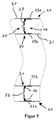
- the embodiment according to FIG. 7 differs from the annular support member (10) FIG. 6a . b in that the thermoelectric thin-layer element (20) applied to the carrier element (10) has a rigid substrate (27).
- the arrangement of the compensation sections (16) and the connecting elements (13a, 13b) corresponds to the structure according to FIG. 2 , so that reference is made to the statements there in full.
- the connecting portions (13a, 13b) of the carrier element (10) are connected to coaxially arranged tubes of a heat sink (30) and heat source (40).
- the carrier element (10) consists in particular of a copper sheet.
- the connecting elements (13 a, b) are connected by soldering, gluing or welding cohesively to the tubes (31, 41) of heat sink and heat source (30, 40).
- the carrier element after FIG. 7 is particularly suitable for applications in the temperature range above 250 degrees Celsius, since the rigid substrate (27) may also consist of high temperature resistant material.
- FIG. 8 shows a module (50) comprising a plurality of identical support elements (10) in one embodiment FIG. 6 or 7 ,
- the support elements (10) are successively spaced evenly on a pipe (31) of the heat sink (30) arranged and connected by means of the connecting elements (13b) cohesively with the lateral surface of the tube (31).
- the connecting elements (13a) arranged on the outer circumference of the annular carrier elements are arranged on an inner jacket tube (33) of the heat source (40).
- the heat source (40) further comprises an outer jacket tube (34) which surrounds the inner jacket tube (33) to form an annular space (35). End plates close end plates (36a, 36b) the annulus (35).
- connecting pieces (52a, 52b) are arranged on the outer jacket tube (34) of the heat source (40).
- a heat transfer medium is conducted via the connecting piece (52a) into the annular space (35) and leaves the annular space via the connecting piece (52b).
Description
Die Erfindung betrifft ein Trägerelement umfassend eine Anbindung an eine Wärmequelle und eine Anbindung an eine Wärmesenke sowie ein auf dem Trägerelement zwischen der Anbindung an die Wärmequelle und der Anbindung an die Wärmesenke angeordnetes thermoelektrisches Dünnschichtelement. Außerdem betrifft die Erfindung ein Modul mit mehreren Trägerelementen.The invention relates to a carrier element comprising a connection to a heat source and a connection to a heat sink as well as a thermoelectric thin-film element arranged on the carrier element between the connection to the heat source and the connection to the heat sink. Moreover, the invention relates to a module with a plurality of carrier elements.
Die direkte Wandlung von Wärme in elektrische Energie ist mit einem als Generator betriebenen thermoelektrischen Element möglich. Man verwendet hierfür vorzugsweise unterschiedlich dotierte Halbleitermaterialien, wodurch sich die Effizienz gegenüber Thermoelementen mit zwei unterschiedlichen und an einem Ende miteinander verbundenen Metallen wesentlich steigern lässt. Gebräuchliche Halbleitermaterialien sind Bi2Te3, PbTe, SiGe, BiSb und FeSi2. Um ausreichend hohe Spannungen zu erzeugen, ist in einem thermoelektrischen Element üblicherweise eine Vielzahl von Thermopaaren elektrisch in Reihe geschaltet.The direct conversion of heat into electrical energy is possible with a thermoelectric element operated as a generator. It is preferable to use differently doped semiconductor materials for this purpose, which can significantly increase the efficiency compared to thermocouples with two different metals joined together at one end. Common semiconductor materials are Bi 2 Te 3 , PbTe, SiGe, BiSb and FeSi 2 . In order to generate sufficiently high voltages, a plurality of thermocouples is usually electrically connected in series in a thermoelectric element.
Die Wirkungsweise eines thermoelektrischen Elementes beruht auf dem thermoelektrischen Effekt, nachfolgend als Seebeck-Effekt bezeichnet. Beim Seebeck-Effekt entsteht zwischen zwei Punkten eines elektrischen Leiters bzw. Halbleiters, die eine verschiedene Temperatur haben, eine elektrische Spannung. Die entstehende Spannung ist bestimmt durch ![]()
- ΔT
- Temperaturdifferenz zwischen zwei Punkten des Leiter/Halbleiters an den Kontaktstellen,
- α
- Seebeck-Koeffizient.
- .DELTA.T
- Temperature difference between two points of the conductor / semiconductor at the contact points,
- α
- Seebeck coefficient.
Herkömmliche thermoelektrische Elemente bestehen aus mehreren Quadern aus thermoelektrisch aktivem Halbleitermaterial, die abwechselnd oben und unten durch Metallbrücken elektrisch leitend miteinander verbunden sind. Die Metallbrücken bilden zugleich die thermischen Kontaktflächen und sind durch eine aufliegende Keramikplatte isoliert.Conventional thermoelectric elements consist of several blocks of thermoelectrically active semiconductor material, which are alternately connected at the top and bottom by metal bridges electrically conductive. The metal bridges at the same time form the thermal contact surfaces and are insulated by a ceramic plate lying on top.
Darüber hinaus sind aus dem Stand der Technik thermoelektrische Dünnschichtelemente bekannt:Moreover, thermoelectric thin-film elements are known from the prior art:
Aus der
Aus der
Aus der
Gute thermoelektrische Materialien sind spröde und mechanisch nur auf Druck belastbar. Zug- und Scherbelastung führen daher nicht zu einer plastischen Verformung, sondern zum Bruch der thermoelektrisch aktiven Materialien. Um die thermoelektrisch aktiven Materialien herkömmlicher thermoelektrischer Elemente trotz unterschiedlicher Ausdehnungen der Wärmequelle und der Wärmesenke nach Möglichkeit nur auf Druck zu belasten, erfolgt die Anbindung der Keramikplatte auf der heißen Seite an die Wärmequelle gleitend. Der im Interesse eines hohen Wirkungsgrades des thermoelektrischen Elementes angestrebte geringe thermische Widerstand zwischen der Wärmequelle und der Keramikplatte erfordert grundsätzlich eine sehr hohe Anpresskraft, die sich jedoch aufgrund der zum Ausgleich unterschiedlicher Ausdehnungen erforderlichen Gleitlagerung verbietet. Um insoweit einen optimalen Kompromiss zu finden, ist über die gesamte Oberfläche der gleitgelagerten Keramikplatte ein gleichförmiger Kraftschluss erforderlich, der nur mit außerordentlich großem, bisher nicht automatisierbaren Herstellungsaufwand realisierbar ist.Good thermoelectric materials are brittle and can only be loaded mechanically under pressure. Tensile and shear stress therefore do not lead to plastic deformation, but to breakage of the thermoelectrically active materials. To the thermoelectrically active materials of conventional thermoelectric elements despite different dimensions of the heat source and the If possible, heat sink only to pressure load, the connection of the ceramic plate on the hot side to the heat source sliding. The desired in the interest of a high efficiency of the thermoelectric element low thermal resistance between the heat source and the ceramic plate basically requires a very high contact pressure, which, however, prohibits due to the necessary to compensate for different expansions slide bearing. In order to find an optimal compromise in this respect, a uniform frictional connection is required over the entire surface of the slide-mounted ceramic plate, which can be realized only with extremely large, previously not automatable production cost.
Aus der
Ausgehend von diesem Stand der Technik liegt der Erfindung die Aufgabe zu Grunde, ein Trägerelement mit einem auf dem Trägerelement angeordneten thermoelektrischen Dünnschichtelement vorzuschlagen, das für die Befestigung des Dünnschichtelementes besonders geeignet ist und das bei guter thermischer Anbindung an eine Wärmequelle und Wärmesenke schädliche Zug- und Scherbeanspruchungen in dem thermoelektrischen Dünnschichtelement, insbesondere in dem thermoelektrisch aktiven Material, vermeidet.Based on this prior art, the present invention seeks to propose a support member having a thermoelectric thin-film element disposed on the support member, which is particularly suitable for the attachment of the thin-film element and the harmful with good thermal connection to a heat source and heat sink tensile and Avoiding shear stresses in the thermoelectric thin-film element, in particular in the thermoelectrically active material.
Diese Aufgabe wird bei einem Trägerelement der eingangs erwähnten Art dadurch gelöst, dass
- das Trägerelement eine Platte zum Aufbringen des thermoelektrischen Dünnschichtelements und an der Platte angeordnete Verbindungselemente für die Anbindung des Trägerelementes an die Wärmequelle und die Wärmesenke aufweist sowie
- mindestens ein elastischer und/oder flexibler Kompensationsabschnitt des Trägerelementes zwischen der Anbindung an die Wärmequelle und der Anbindung an die Wärmesenke derart eingerichtet ist, dass er unterschiedliche Ausdehnungen der Wärmequelle und der Wärmesenke durch eine Formänderung des Kompensationsabschnitts ausgleicht.
- the carrier element has a plate for applying the thermoelectric thin-film element and arranged on the plate connecting elements for the connection of the carrier element to the heat source and the heat sink and
- at least one elastic and / or flexible compensation section of the carrier element between the connection to the heat source and the connection to the heat sink is arranged such that it compensates for different expansions of the heat source and the heat sink by a change in shape of the compensation section.
Die unterschiedlichen Ausdehnungen der Wärmequelle und der Wärmesenke werden von dem Kompensationsabschnitt vollständig durch Formänderung aufgenommen, so dass die übrigen Bereiche des Trägerelementes aufgrund der thermisch unterschiedlichen Ausdehnungen nicht verformt werden. Insbesondere das für Scherbelastungen empfindliche thermoelektrisch aktive Material wird in den übrigen Bereichen angeordnet und dadurch keinen Scherbelastungen ausgesetzt.The different dimensions of the heat source and the heat sink are completely absorbed by the compensation section by a change in shape, so that the remaining regions of the carrier element are not deformed due to the thermally different expansions. In particular, the thermoelectrically active material which is sensitive to shearing loads is arranged in the remaining areas and is thus not exposed to any shear loads.
Der erfindungsgemäß vorgesehene Kompensationsabschnitt erlaubt eine stoffschlüssige Anbindung des Trägerelementes an die Wärmequelle und die Wärmesenke. Durch eine stoffschlüssige Anbindung entfällt die Notwendigkeit, große Druckkräfte zwischen Wärmequelle bzw. Wärmesenke und der Anbindung des Trägerelements an die Wärmequelle bzw. Wärmesenke aufzubauen, um einen geringen thermischen Widerstand zu erzielen. Außerdem erlaubt die stoffschlüssige Anbindung größere Fertigungstoleranzen sowohl des Trägerelementes als auch der Wärmequelle bzw. Wärmesenke. Etwaige Fertigungstoleranzen können beispielsweise durch einen Kleber oder ein Lot zur Herstellung der stoffschlüssigen Verbindung ausgeglichen werden.The inventively provided compensation section allows a material connection of the carrier element to the heat source and the heat sink. By a cohesive connection eliminates the need to build large pressure forces between the heat source or heat sink and the connection of the support member to the heat source or heat sink to achieve a low thermal resistance. In addition, the cohesive connection allows greater manufacturing tolerances of both the carrier element and the heat source or heat sink. Any manufacturing tolerances can be compensated for example by an adhesive or a solder for the production of the cohesive connection.
Das Trägerelement weist eine Platte zum Aufbringen des thermoelektrischen Dünnschichtelementes auf. Die ebene Oberfläche ist für die Befestigung des thermoelektrischen Dünnschichtelementes besonders geeignet. Darüber hinaus lässt sich in eine relativ dünne Platte der Kompensationsabschnitt unmittelbar, insbesondere durch Prägen einbringen. Für die vorzugsweise stoffschlüssige Anbindung des Trägerelementes an die Wärmequelle und die Wärmesenke sind an der Platte Verbindungselemente angeordnet.The carrier element has a plate for applying the thermoelectric thin-film element. The flat surface is particularly suitable for the attachment of the thermoelectric thin-film element. In addition, the compensation section can be introduced directly into a relatively thin plate, in particular by embossing. For the preferably cohesive connection of the carrier element to the heat source and the heat sink connecting elements are arranged on the plate.
Um eine hohe Zyklenfestigkeit zu erreichen, weist jeder Kompensationsabschnitt vorzugsweise ein linear-elastisches Verhalten auf.In order to achieve a high cycle stability, each compensation section preferably has a linear-elastic behavior.
Der Kompensationsabschnitt kann durch Prägung erzeugte Erhebungen und/oder Vertiefungen aufweisen, um die Belastungen aufgrund der unterschiedlichen Ausdehnungen der Wärmequelle und Wärmesenke auszugleichen.The compensation section may have embossed protrusions and / or depressions to compensate for the stresses due to the different expansions of the heat source and heat sink.
Vorzugsweise weist der Kompensationsabschnitt jedoch eine genoppte Struktur mit einer zweidimensionalen Anordnung von Erhebungen und Vertiefungen auf. Eine solche Noppenstruktur lässt Kompensationsbewegungen der in dem Kompensationsabschnitt auftretenden Kräfte in allen Raumrichtungen zu.However, the compensation section preferably has a knobbed structure with a two-dimensional arrangement of Elevations and depressions. Such a nub structure allows compensation movements of the forces occurring in the compensation section in all spatial directions.
Der elastische Kompensationsabschnitt kann darüber hinaus nach Art eines Rohrkompensators als elastischer Balg - auch als Faltenbalg bezeichnet- ausgestaltet sein. Jeder Balg kann mit mindestens einem, vorzugsweise mehreren Schlitzen versehen sein, die sich quer zum Verlauf der Falten des Balgs erstrecken. Sofern die Falten des Balgs rechtwinklig zur Hauptausdehnungrichtung der Wärmequelle verlaufen, werden durch die Schlitze Ausdehnungen der Wärmequelle gegenüber der Wärmesenke senkrecht zur Hauptausdehnungsrichtung kompensiert. Ähnlich wie der mit Noppenstruktur versehene Kompensationsabschnitt lässt auch der geschlitzte Balg Kompensationsbewegungen der in dem Kompensationsabschnitt auftretenden Kräfte in allen Raumrichtungen zu.The elastic compensation section can also be designed in the manner of a pipe compensator as an elastic bellows - also known as bellows. Each bellows may be provided with at least one, preferably a plurality of slots which extend transversely to the course of the folds of the bellows. If the folds of the bellows are perpendicular to the main direction of expansion of the heat source, expansions of the heat source with respect to the heat sink perpendicular to the main extension direction are compensated by the slots. Similar to the compensated portion provided with nub structure and the slotted bellows allows compensating movements of the forces occurring in the compensation section in all spatial directions.
Der elastische Kompensationsabschnitt kann aus demselben Material wie die übrigen Bereiche des Trägerelementes bestehen. Als Werkstoff für das Trägerelement und den geprägten elastischen Kompensationsabschnitt kommen beispielsweise Metalle zum Einsatz, die insbesondere aggressiven Medien und hohen Temperaturen gut standhalten können. Der elastische Kompensationsabschnitt kann jedoch abweichend zu den übrigen Bereichen des Trägerelementes auch aus Weichstoff, wie technischen Geweben oder Elastomeren bestehen.The elastic compensation portion may be made of the same material as the remaining portions of the support member. As a material for the carrier element and the embossed elastic compensation section metals are used, for example, which can withstand aggressive media and high temperatures well. However, the elastic compensation section can deviate from the other areas of the carrier element also made of soft material, such as technical fabrics or elastomers.
Das thermoelektrische Dünnschichtelement weist ein Substrat und auf dem Substrat aufgebrachtes thermoelektrisch aktives Material auf. Das thermoelektrisch aktive Material weist eine Schichtdicke von maximal 150 µm auf.The thermoelectric thin-film element has a substrate and thermoelectrically active material applied to the substrate. The thermoelectrically active material has a layer thickness of not more than 150 μm.
Das Substrat ist elektrisch isolierend, um voneinander getrennte Bereiche aus thermoelektrisch aktivem Material abwechselnd auf der heißen und kalten Seite des Dünnschichtelementes durch auf dem Substrat aufgebrachte metallisierte Bereiche elektrisch leitend miteinander zu verbinden. Um einen Wärmefluss von der heißen zur kalten Seite durch das Substrat hindurch zu vermeiden, weist das Material des Substrats eine geringe Wärmeleitfähigkeit auf. Die Bereiche aus thermoelektrisch aktivem Material sind vorzugsweise in Reihe geschaltet.The substrate is electrically insulating in order to connect mutually separate regions of thermoelectrically active material alternately on the hot and cold side of the thin-film element by metallized regions deposited on the substrate. In order to avoid a heat flow from the hot to the cold side through the substrate, the material of the substrate has a low thermal conductivity. The regions of thermoelectrically active material are preferably connected in series.
Das Substrat kann flexibel, beispielsweise als Polyimid-Folie ausgebildet sein. Das als Folie ausgebildete Substrat ist vorzugsweise streifenförmig mit der heißen und kalten Seite an gegenüberliegenden Längsseiten des Streifens. Die flexible Folie kann auch dem Kompensatorabschnitt ganz oder teilweise überlappend auf dem Trägerelement angeordnet und befestigt werden. Bei der Anordnung und Befestigung der Folie auf dem Trägerelement ist jedoch darauf zu achten, dass sich kein thermoelektrisch aktives Material im Bereich oberhalb des Kompensatorabschnitts befindet.The substrate may be flexible, for example formed as a polyimide film. The film-formed substrate is preferably strip-shaped with the hot and cold sides on opposite longitudinal sides of the strip. The flexible film can also be arranged and fastened to the compensator section completely or partially overlapping on the carrier element. When arranging and fixing the film on the carrier element, however, care must be taken that no thermoelectrically active material is located in the region above the compensator section.
Das Substrat kann auch aus einem biegesteifen Material bestehen. In diesem Fall befindet sich jeder Kompensatorabschnitt in einem nicht mit dem Substrat überlappenden Bereich des Trägerelementes. Andernfalls würde das elastische und/oder flexible Verhalten des Kompensatorabschnitts durch das biegesteife Material des Substrats unterbunden.The substrate may also consist of a rigid material. In this case, each compensator section is located in a region of the carrier element which does not overlap with the substrate. Otherwise, the elastic and / or flexible behavior of the Kompensatorabschnitts would be prevented by the rigid material of the substrate.
Das thermoelektrische Dünnschichtelement ist stoffschlüssig mit einer insbesondere ebenen Oberfläche des Trägerelements verbunden, beispielsweise durch Verkleben oder Verlöten. Um das Verlöten zu erleichtern, kann die zu verlötende Rückseite des Substrats metallisiert sein.The thermoelectric thin-film element is integrally bonded to a particular flat surface of the carrier element, for example by gluing or soldering. To facilitate soldering, the back side of the substrate to be soldered can be metallized.
Sofern auf dem als Platte ausgestalteten Tragelement ein thermoelektrisches Dünnschichtelement mit einem flexiblen Substrat angebracht ist, kann die Platte und das Substrat in den überlappenden Abschnitten miteinander fluchtende Schlitze aufweisen, die in den überlappenden Abschnitten auftretende Spannungen ausgleichen. Die Schlitze in der Platte und dem Substrat verlaufen zu diesem Zweck insbesondere senkrecht zur Hauptausdehnungsrichtung der Wärmequelle. Ist der Kompensationsabschnitt als Balg ausgebildet, verlaufen die Schlitze senkrecht zu dessen Falten.If a thermoelectric thin film element with a flexible substrate is mounted on the supporting element configured as a plate, the plate and the substrate in the overlapping sections may have mutually aligned slots which compensate for stresses occurring in the overlapping sections. The slits in the plate and the substrate run for this purpose, in particular perpendicular to the main extension direction of the heat source. If the compensation section is designed as a bellows, the slots run perpendicular to its folds.
Für eine vorzugsweise stoffschlüssige Anbindung des Trägerelementes an die Wärmequelle und die Wärmesenke sind an der Platte Verbindungselemente angeordnet, die sich winklig, insbesondere senkrecht zur Plattenebene erstrecken. Sofern die Verbindungselemente als Laschen ausgeführt sind, können diese durch Abkanten der Platte an gegenüberliegenden Längsseiten hergestellt werden. Zur Anbindung des Trägerelementes an rohrförmige Wärmequellen bzw. Wärmesenken sind die Verbindungselemente vorzugsweise hülsenförmig ausgebildet. Die Größe der Kontaktfläche zwischen der Hülse und dem Rohr führt zu einer sehr guten thermischen Anbindung. Sofern die Hülse die Platte durchsetzt, kann das Rohr der Wärmesenke bzw. Wärmequelle durch die Hülse hindurchgeführt werden. Um eine gleichmäßige Wärmeeinkopplung bzw. Auskopplung zu erreichen, sind mehrere Verbindungselemente gleichmäßig entlang der heißen bzw. kalten Seite des thermoelektrischen Dünnschichtelementes angeordnet. Ist nur ein Verbindungselement an der heißen und ein Verbindungselement an der kalten Seite des thermoelektrischen Dünnsichtelementes angeordnet, entspricht die Längserstreckung des Verbindungselementes in der Plattenebene in etwa der Längserstreckung des thermoelektrischen Dünnschichtelementes entlang der heißen und kalten Seite.For a preferably cohesive connection of the carrier element to the heat source and the heat sink connecting elements are arranged on the plate, which extend at an angle, in particular perpendicular to the plane of the plate. If the connecting elements are designed as tabs, they can be made by bending the plate on opposite longitudinal sides. To connect the carrier element to tubular heat sources or heat sinks, the connecting elements are preferably designed sleeve-shaped. The size of the contact surface between the sleeve and the tube leads to a very good thermal connection. If the sleeve passes through the plate, the tube of the heat sink or heat source can be passed through the sleeve. In order to achieve a uniform heat coupling or decoupling, a plurality of connecting elements are arranged uniformly along the hot or cold side of the thermoelectric thin-film element. If only one connection element is arranged on the hot side and one connection element on the cold side of the thermoelectric thin-section element, the longitudinal extension of the connection element in the plane of the plate corresponds approximately to the longitudinal extent of the thermoelectric thin-layer element along the hot and cold sides.
Um die Wärmeleitung zur Wärmequelle bzw. Wärmesenke zu verbessern, kann das Tragelement in Teilbereichen mit einer Funktionsschicht versehen sein, die eine höhere Wärmeleitfähigkeit als das Tragelement aufweist. Das Tragelement besteht beispielsweise aus Edelstahl und die Funktionsschicht aus Kupfer. Die Funktionsschicht wird insbesondere im Bereich der Anbindung zur Wärmequelle bzw. Wärmesenke sowie im Überlappungsbereich zwischen Tragelement und thermoelektrischem Dünnschichtelement aufgebracht. In dem Bereich, in dem sich das thermoelektrisch aktive Material befindet, ist die Funktionsschicht unterbrochen, um Verlustwärmeströme zwischen der kalten und heißen Seite des thermoelektrischen Elementes zu vermeiden, das mit seinem Substrat auf die Funktionsschicht aufgebracht ist. Die Unterbrechung der Funktionsschicht kann als Spalt ausgeführt sein.In order to improve the heat conduction to the heat source or heat sink, the support element may be provided in partial areas with a functional layer having a higher thermal conductivity than the support element. The support element consists for example of stainless steel and the functional layer of copper. The functional layer is applied in particular in the region of the connection to the heat source or heat sink and in the overlap region between the support element and the thermoelectric thin-film element. In the region in which the thermoelectrically active material is located, the functional layer is interrupted in order to avoid loss heat flows between the cold and hot side of the thermoelectric element, which is applied with its substrate on the functional layer. The interruption of the functional layer can be designed as a gap.
Abhängig von der Wärmeleitfähigkeit des Tragelementes kann eine weitere Entkopplung der Wärmequelle von der Wärmesenke dadurch erreicht werden, dass das Tragelement, insbesondere dessen Platte, durch mindestens einen Schlitz geteilt ist, wobei ein erster Teil der Platte auf einer Seite des Schlitzes mit der Wärmequelle und ein zweiter Teil der Platte auf der gegenüberliegenden Seite des Schlitzes mit der Wärmesenke in wärmeleitender Verbindung steht.Depending on the thermal conductivity of the support element, a further decoupling of the heat source from the heat sink can be achieved by dividing the support element, in particular its plate, by at least one slot, wherein a first part of the plate is connected to the heat source on one side of the slot second part of the plate on the opposite side of the slot with the heat sink in thermally conductive connection.
Aus Stabilitätsgründen können der erste und zweite Teil der Platte durch mindestens einen, vorzugsweise mehrere den Schlitz überbrückende im Verhältnis zur Längserstreckung des Schlitzes schmale Stege miteinander verbunden sein. Über die im Verhältnis zur Schlitzlänge schmalen Stege fließen nur geringe parasitäre Verlustwärmeströme von der heißen zur kalten Seite. Sofern eine Funktionsschicht auf dem Trägerelement vorgesehen ist, ist diese im Bereich der Stege unterbrochen.For reasons of stability, the first and second part of the plate can be connected to each other by at least one, preferably a plurality of bridges bridging the slot, which are narrow relative to the longitudinal extension of the slot. About the narrow in relation to the slot length webs flow only low parasitic heat losses from the hot to the cold side. If a functional layer is provided on the carrier element, this is interrupted in the region of the webs.
Sofern derartige Stege vorgesehen sind, kann der Stegansatz an dem ersten und/oder zweiten Teil der Platte als Kompensationsabschnitt ausgebildet sein. Um im Stegansatz ein elastisches und/oder flexibles Verhalten zu erzielen, können die Materialstärke und/oder die Materialeigenschaften des Steges im Bereich des Ansatzes gegenüber den übrigen Bereichen des Trägerelementes verändert werden. Das thermoelektrisch aktive Material des Dünnschichtelementes befindet sich ausschließlich in einem Bereich oberhalb des Schlitzes in Bezug auf die Plattenoberfläche, wobei die metallisierten Bereiche des Dünnschichtelementes abwechselnd auf dessen heißer Seite mit dem ersten Teil auf dessen kalter Seite mit dem zweiten Teil der Platte bzw. Funktionsschicht wärmeleitend verbunden sind. Die als Kompensationsabschnitte wirkenden Stegansätze legen auf beiden Seiten des thermoelektrisch aktiven Materials jeweils eine Biegelinie zur Aufnahme der unterschiedlichen Ausdehnungen der Wärmequelle und Wärmesenke fest. Die Biegelinien verlaufen entlang der Übergangsbereiche des thermoelektrisch aktiven Materials zu den metallisierten Kontaktbereichen auf dem flexiblen Substrat. In diesem Übergangsbereich kann das Substrat einer Drehbewegung um die Biegelinie des Trägerelementes folgen, ohne dass thermoelektrisch aktive Material durch Scherkräfte zu belasten. Sofern der Schlitz beispielsweise eine Schlitzbreite von 4 mm und das thermoelektrisch aktive Material in Richtung der Schlitzbreite eine Erstreckung von 2 mm aufweist, entsteht bei zentraler Anordnung des thermoelektrisch aktiven Materials in dem Schlitz ein Übergangsbereich von jeweils 1 mm auf beiden Seiten. In diesem Übergangsbereich verläuft die Biegelinie.If such webs are provided, the web extension may be formed on the first and / or second part of the plate as a compensation section. In order to achieve an elastic and / or flexible behavior in the web approach, the material thickness and / or the material properties of the web in the region of the attachment can be changed relative to the other regions of the carrier element. The thermoelectrically active material of the thin film element is located exclusively in an area above the slot with respect to the plate surface, the metallized areas of the thin film element alternately thermally conductive on its hot side with the first part on its cold side with the second part of the plate or functional layer are connected. The web projections acting as compensation sections define on both sides of the thermoelectrically active material in each case a bending line for receiving the different expansions of the heat source and heat sink. The bend lines extend along the transition regions of the thermoelectrically active material to the metallized contact regions on the flexible substrate. In this transition region, the substrate can follow a rotational movement about the bending line of the carrier element, without stressing thermoelectrically active material by shear forces. If, for example, the slot has a slot width of 4 mm and the thermoelectrically active material has an extension of 2 mm in the direction of the slot width, a transitional area of 1 mm in each case arises on both sides with a central arrangement of the thermoelectrically active material in the slot. In this transition area, the bending line runs.
In einer vorteilhaften Ausgestaltung der Erfindung umfasst die Wärmesenke und/oder Wärmequelle mindestens ein Rohr für einen Wärmeträger, an das das Trägerelement angebunden ist. Hierdurch lässt sich beispielsweise die Abwärme aus einem Heizkreislauf in einem oder mehreren thermoelektrischen Dünnschichtelementen nutzen.In an advantageous embodiment of the invention, the heat sink and / or heat source comprises at least one tube for a heat transfer medium, to which the carrier element is connected. This allows, for example, the waste heat from a Use heating circuit in one or more thermoelectric thin-film elements.
Indem sich die Rohre der Wärmequelle bzw. Wärmesenke und die diese aufnehmenden hülsenförmigen Verbindungselemente senkrecht zu der Platte des Trägerelementes erstrecken, verläuft der Wärmestrom in den thermoelektrischen Dünnschichtelementen quer zur Fließrichtung des Wärmeträgers in jedem Rohr. Hierdurch wird ein Temperaturabfall entlang des thermoelektrischen Dünnschichtelementes vermieden, was eine deutliche Leistungssteigerung zur Folge hat. Darüber hinaus erlaubt eine Anordnung der Trägerelemente quer zur Längserstreckung der Wärmequelle und Wärmesenke die einwandfreie Funktion des Kompensationsabschnitts in dem Stegansatz.As the tubes of the heat source or heat sink and the sleeve-shaped connecting elements receiving them extend perpendicularly to the plate of the carrier element, the heat flow in the thermoelectric thin-film elements runs transversely to the flow direction of the heat carrier in each tube. As a result, a temperature drop along the thermoelectric thin-film element is avoided, resulting in a significant increase in performance. In addition, an arrangement of the carrier elements transversely to the longitudinal extent of the heat source and heat sink allows the proper functioning of the compensation section in the web approach.
Sofern jedes Rohr einer Wärmesenke und/oder Wärmequelle an mehrere Trägerelemente angebunden ist, lässt sich eine Kaskade von thermoelektrischen Dünnschichtelementen zu einem Modul zusammenfassen. Die auf den mehreren Trägerelementen angebrachten Dünnschichtelemente können abhängig vom Temperaturverlauf entlang der Rohre teilweise elektrisch in Serie oder parallel geschaltet werden.If each tube of a heat sink and / or heat source is connected to a plurality of carrier elements, a cascade of thermoelectric thin-film elements can be combined to form a module. Depending on the temperature profile along the tubes, the thin-film elements mounted on the plurality of carrier elements can be partially electrically connected in series or in parallel.
In einer Ausführungsform der Erfindung ist die Platte des Trägerelementes ringförmig und durch einen Schlitz in zwei konzentrische Kreisringe geteilt. Ein derart geformtes Tragelement erlaubt eine Anbindung an eine lang gestreckte, insbesondere rohrförmige Wärmequelle und Wärmesenke, die beide senkrecht zu der ringförmigen Platte verlaufen. Die Verbindungselemente zur Anbindung an die Wärmequelle und Wärmesenke erstrecken sich ebenfalls senkrecht zur Plattenebene.In one embodiment of the invention, the plate of the support member is annular and divided by a slot in two concentric circular rings. Such a shaped support member allows connection to an elongated, in particular tubular heat source and heat sink, both of which extend perpendicular to the annular plate. The connecting elements for connection to the heat source and heat sink also extend perpendicular to the plane of the plate.
Nachfolgend wird die Erfindung anhand der Figuren näher erläutert. Es zeigen:
- Figur 1a
- eine schematische Seitenansicht eines ersten Ausführungsbeispiels eines Trägerelementes mit einem flexiblen thermoelektrischen Dünnschichtelement vor und nach einer thermomechanischen Ausdehnung,
- Figur 1b
- eine Vorderansicht des Trägerelementes nach
Figur 1a , - Figur 2
- eine schematische Seitenansicht eines zweiten Ausführungsbeispiels eines erfindungsgemäßen Trägerelementes mit einem thermoelektrischen Dünnsichtelement, das auf einem biegesteifen Substrat angeordnet ist,
- Figur 3a
- eine bevorzugte Ausführungsform eines Kompensationsabschnitts mit einer Noppenstruktur in perspektivischer Ansicht,
- Figur 3b
- Seitenansichten der Noppenstruktur nach
Figur 3a , - Figur 4a
- eine Vorderansicht eines dritten Ausführungsbeispiels eines Trägerelementes angebunden an eine ein Rohrbündel umfassende Wärmequelle und Wärmesenke,
- Figur 4b
- ein mit mehreren Trägerelementen nach
Figur 4a aufgebautes Modul in perspektivischer Ansicht, - Figur 5a
- ein Vorderansicht eines vierten Ausführungsbeispiels eines Trägerelementes mit ovaler Kontur,
- Figur 5b
- eine Vorderansicht eines fünften Ausführungsbeispiels eines Trägerelementes angebunden an eine jeweils ein rechteckiges Rohr umfassende Wärmequelle und Wärmesenke,
- Figur 5c
- eine Vorderansicht eines sechsten Ausführungsbeispiels eines Trägerelementes mit Anbindung an eine zentrale Wärmequelle und zwei Wärmesenken,
- Figur 6a
- ein siebtes Ausführungsbeispiel eines ringförmigen Trägerelementes mit darauf angebrachtem flexiblen thermoelektrischen Dünnschichtelement in Vorderansicht und Seitenansicht,
- Figur 6b
- eine Darstellung entsprechend
Figur 6a , jedoch ohne das thermoelektrische Dünnschichtelement, - Figur 7
- ein weiteres Ausführungsbeispiel eines ringförmigen Trägerelementes mit darauf angeordnetem thermoelektrischen Dünnschichtelement mit biegesteifem Substrat in Seitenansicht,
- Figur 8a
- ein mit mehreren Trägerelementen nach
Figuren 6 oder7 aufgebautes Modul in Seitenansicht sowie - Figur 8b
- das Modul nach
Figur 8 a in perspektivischer Ansicht.
- FIG. 1a
- FIG. 2 shows a schematic side view of a first exemplary embodiment of a carrier element with a flexible thermoelectric thin-film element before and after a thermo-mechanical expansion, FIG.
- FIG. 1b
- a front view of the support element according to
FIG. 1a . - FIG. 2
- FIG. 2 shows a schematic side view of a second exemplary embodiment of a carrier element according to the invention with a thermoelectric thin-section element which is arranged on a rigid substrate, FIG.
- FIG. 3a
- a preferred embodiment of a compensation section with a knob structure in perspective view,
- FIG. 3b
- Side views of the nub structure after
FIG. 3a . - FIG. 4a
- a front view of a third embodiment of a support member connected to a tube bundle comprising heat source and heat sink,
- FIG. 4b
- one with several carrier elements
FIG. 4a constructed module in perspective view, - FIG. 5a
- a front view of a fourth embodiment of a carrier element with an oval contour,
- FIG. 5b
- a front view of a fifth embodiment of a support member connected to each comprising a rectangular tube heat source and heat sink,
- FIG. 5c
- a front view of a sixth embodiment of a support member with connection to a central heat source and two heat sinks,
- FIG. 6a
- A seventh embodiment of an annular support member having mounted thereon flexible thermoelectric thin-film element in front view and side view,
- FIG. 6b
- a representation accordingly
FIG. 6a but without the thermoelectric thin-film element, - FIG. 7
- a further embodiment of an annular support element with thermoelectric thin-film element arranged thereon with a rigid substrate in side view,
- FIG. 8a
- one with several carrier elements
FIGS. 6 or7 built-in module in side view as well - FIG. 8b
- the module after
FIG. 8 a in perspective view.
Wie insbesondere aus
An den Seitenrändern der Platte (11) sind der erste Teil (11a) und der zweite Teile (11b) der Platte (11) durch einen den Schlitz (14) überbrückenden Steg (15) miteinander verbunden. Die Stegansätze (15a) an dem ersten Teil (11a) und die Stegansätze (15b) an den zweiten Teil (11b) der Platte (11) definieren zwei Biegelinien als Kompensationsabschnitte (16), die parallel zu den Längsrändern (12) der Platte (11) verlaufen. Die derart gebildeten Kompensationsabschnitte (16) des Trägerelementes (10) gleichen unterschiedliche thermomechanische Ausdehnungen der Wärmequelle (40) und der Wärmesenke (30) aus.At the side edges of the plate (11), the first part (11a) and the second part (11b) of the plate (11) are interconnected by a web (15) bridging the slot (14). The web projections (15a) on the first part (11a) and the web extensions (15b) on the second part (11b) of the plate (11) define two bending lines as compensation sections (16) extending parallel to the longitudinal edges (12) of the plate (11). The compensation sections (16) of the carrier element (10) thus formed compensate for different thermo-mechanical expansions of the heat source (40) and the heat sink (30).
Das thermoelektrische Dünnschichtelement (20) weist in dem Ausführungsbeispiel nach
Zur Herstellung der wärmeleitenden Verbindung ist das Trägerelement (10) in Teilbereichen mit einer Funktionsschicht (17) (schraffierte Darstellung) versehen, die eine höhere Wärmeleitfähigkeit als das Trägerelement (10) aufweist. Die Funktionsschicht besteht in dem Ausführungsbeispiel aus Kupfer. Die Platte (11) des Trägerelementes (10) ist im Bereich des ersten und zweiten Teils (11a, 11b) der Platte (11) mit der Funktionsschicht (17) versehen. Im Bereich der Stege (15) ist indes keine Funktionsschicht angebracht, um parasitäre Verlustwärmeströme zwischen der heißen und kalten Seite (24, 25) zu reduzieren. Die Funktionsschicht (17) ist darüber hinaus auf den mit den Rohren (31, 41) in Kontakt gelangenden Oberflächen der Verbindungselemente (13a, 13b) aufgebracht, um eine gute thermische Anbindung an die Wärmesenke (30) bzw. Wärmequelle (14) zu erreichen.To produce the heat-conducting connection, the carrier element (10) is provided in partial regions with a functional layer (17) (hatched representation), which has a higher thermal conductivity than the carrier element (10). The functional layer consists in the embodiment of copper. The plate (11) of the carrier element (10) is provided in the region of the first and second parts (11a, 11b) of the plate (11) with the functional layer (17). In the area of the webs (15), however, is no Functional layer attached to reduce parasitic leakage heat flows between the hot and cold side (24, 25). The functional layer (17) is also applied to the surfaces of the connecting elements (13a, 13b) which come into contact with the tubes (31, 41) in order to achieve a good thermal connection to the heat sink (30) or heat source (14) ,
Um das flexible Substrat (21) der thermoelektrischen Dünnschichtelementes (20) auf der Funktionsschicht (17) des Trägerelementes zu befestigen, ist das Substrat auf seiner rückwärtigen, der Funktionsschicht (17) zugewandten Seite mit einer Beschichtung, insbesondere Metallisierung versehen, die ein Auflöten des thermoelektrischen Dünnschichtelementes (20) auf dem mit der Funktionsschicht (17) versehenen Trägerelement (10) ermöglicht.In order to fasten the flexible substrate (21) of the thermoelectric thin-film element (20) on the functional layer (17) of the carrier element, the substrate is provided on its rear side facing the functional layer (17) with a coating, in particular metallization, which performs a soldering of the Thermoelectric thin-film element (20) on the provided with the functional layer (17) support element (10).
Insbesondere aus der Seitenansicht nach
Das Trägerelement (10) nach
Bei Erwärmung des Rohres (41) der Wärmequelle (40) dehnt sich das Rohr (41) relativ zu dem Rohr (31) der Wärmesenke (30) in erster Linie quer zur Oberfläche der Platte (11) aus, wie dies in der rechten Bildhälfte der
In dem Ausführungsbeispiel nach
Das Trägerelement (10) nach
Bei Erwärmung des Rohres (41) der Wärmequelle (40) dehnt sich das Rohr (41) relativ zu dem Rohr (31) der Wärmesenke (30) in erster Linie quer zur Oberfläche der Platte (11) aus. Spannungen aufgrund der thermomechanischen Ausdehnung zwischen der Wärmequelle (40) und der Wärmesenke (30) werden in die elastischer Balge (18) des Trägerelementes (10) eingeleitet und bewirken durch deren Verformung den Ausgleich der unterschiedlichen Ausdehnungen von Wärmequelle (40) und Wärmesenke (30). Das auf der Platte (11) angeordnete thermoelektrische Dünnschichtelement (20) wird nicht belastet.Upon heating the tube (41) of the heat source (40), the tube (41) expands relative to the tube (31) of the heat sink (30) primarily transverse to the surface of the plate (11). Tensions due to the thermo-mechanical expansion between the heat source (40) and the heat sink (30) are introduced into the elastic bellows (18) of the carrier element (10) and cause the compensation of the different expansions of heat source (40) and heat sink (30 ). The thermoelectric thin-film element (20) arranged on the plate (11) is not loaded.
Das Trägerelement (10) nach
Das Trägerelement (10) nach
Bei Erwärmung der Rohre des Rohrbündels (42) dehnt sich die Wärmequelle (40) relativ zu den Rohren des Rohrbündels (32) der Wärmesenke (30) in erster Linie quer zur Oberfläche der Platte (11) aus. Spannungen aufgrund der unterschiedlichen Ausdehnungen zwischen der Wärmequelle (40) und der Wärmesenke (30) werden in die Stege (15) des Trägerelementes (10) eingeleitet und bewirken in den Stegansätzen (15a, 15b) eine Biegebewegung, um die durch die Stegansätze (15a, 15b) definierten Biegelinien, die parallel zu den Längsrändern (12) der Platte (11) verlaufen. Durch die Biegung um die in der Plattenebene liegenden Biegelinien lassen sich die Ausdehnungen quer zur Plattenebene vollständig in den Kompensationsabschnitten (16) ausgleichen.When heating the tubes of the tube bundle (42), the heat source (40) expands relative to the tubes of the tube bundle (32) of the heat sink (30) primarily transversely to the surface of the plate (11). Stresses due to the different expansions between the heat source (40) and the heat sink (30) are introduced into the webs (15) of the carrier element (10) and cause in the web extensions (15a, 15b) a bending movement to the by the web projections (15a , 15b) defined bending lines, which extend parallel to the longitudinal edges (12) of the plate (11). Due to the bending around the bending lines lying in the plane of the plate, the expansions transversely to the plane of the plate can be completely compensated in the compensation sections (16).
Bei dem Ausführungsbeispiel des Trägerelementes nach
Die Ausführungsform des Trägerelementes (10) nach
Das Trägerelement (10) nach
Im Bereich der Längsränder (12) des Trägerelementes erstrecken sich in gleicher Richtung wie das Verbindungselement (13a) zwei als lang gestreckte rechteckige Hülsen ausgebildete Verbindungselemente (13b) zur Anbindung des Trägerelementes an jeweils ein im Querschnitt rechteckiges Rohr (31) einer Wärmsenke (30). Zwischen dem Verbindungselement (13a) und den beiden Verbindungselementen (13b) ist die Platte (11) des Trägerelementes jeweils durch einen Schlitz (14) geteilt, wobei jeweils ein erster Teil (11a) der Platte (11) auf einer Längsseite des Schlitzes (14) mit der Wärmequelle (40) und jeweils ein zweiter Teil (11b) der Platte (11) auf der gegenüberliegenden Seite jedes Schlitzes (14) mit einem der beiden Rohre (31) der Wärmesenke (30) in wärmeleitender Verbindung steht. Zu beiden Seiten der beiden Schlitze (14) befinden sich Verbindungsstege (15), deren Stegansätze (15a, 15b) die Kompensationsabschnitte (16) des Trägerelementes zwischen der Anbindung an die Wärmequelle (40) und der Anbindung an die Wärmesenken (30) darstellen.In the region of the longitudinal edges (12) of the carrier element extending in the same direction as the connecting element (13 a) formed as elongated rectangular sleeves connecting elements (13 b) for connection of the support member to a respective rectangular cross-section tube (31) of a heat sink (30) , Between the connecting element (13a) and the two connecting elements (13b), the plate (11) of the carrier element is divided by a slot (14), wherein in each case a first part (11a) of the plate (11) on a longitudinal side of the slot (14 ) with the heat source (40) and in each case a second part (11b) of the plate (11) on the opposite side of each slot (14) with one of the two tubes (31) of the heat sink (30) in heat-conducting connection. On both sides of the Both slots (14) are connecting webs (15), the web projections (15a, 15b) represent the compensation sections (16) of the support element between the connection to the heat source (40) and the connection to the heat sinks (30).
Die
Das ringförmige Trägerelement (10) ermöglicht eine koaxiale Anordnung von Wärmequelle (40) und Wärmesenke (30), wie sie nachfolgend anhand der
Das Ausführungsbeispiel nach
Claims (26)
- A carrier element (10), comprising a connection to a heat source (40) and a connection to a heat sink (30) as well as a thermoelectric thin-film element (20) having a hot side and a cold side (24, 25) arranged on the carrier element (10) between the connection to the heat source (40) and the connection to the heat sink (30), wherein the hot side (24) is connected in a heat-conducting manner to the connection to the heat source (40), and the cold side (25) is connected in a heat-conducting manner to the connection to the heat sink (30), characterized in that- the carrier element (10) comprises a plate (11) for application of the thermoelectric thin-film element (20) and has connecting elements (13a, b) disposed on the plate (10) for connection of the carrier element (10) to the heat source (40) and the heat sink (30) and- at least one elastic and/or flexible compensating section (16) of the carrier element (10) between the connection to the heat source (40) and the connection to the heat sink (30) is adapted in such a manner that said compensating section compensates for different expansions of the heat source and the heat sink by a change of shape of the compensating section (16).
- The carrier element according to claim 1, characterized in that the compensating section (16) exhibits linear-elastic behaviour.
- The carrier element according to claim 1 or 2, characterized in that the compensating section (16) comprises elevations (16a) and/or depressions (16b).
- The carrier element according to any one of claims 1 or 2, characterized in that the compensating section (16) comprises a nubby structure.
- The carrier element according to claim 1 or 2, characterized in that the compensating section (16) is configured as an elastic bellows (18).
- The carrier element according to claim 1 or 2, characterized in that the compensating section (16) consists of a soft material.
- The carrier element according to any one of claims 1 to 6, characterized in that the thermoelectric thin-film element (20) comprises a substrate (21, 27) and a thermoelectrically active material (22) applied to the substrate (21, 27).
- The carrier element according to claim 7, characterized in that areas (23) of the thermoelectrically active material (22), which are separated from each other are connected to one another in an electrically conducting manner by metalized areas (26) alternately on the hot and cold side (24, 25) of the thin-film element (20).
- The carrier element according to claim 7 or 8, characterized in that the substrate (21) consists of a flexible material.
- The carrier element according to claim 7 or 8, characterized in that the substrate (27) consists of a rigid material.
- The carrier element according to any one of claims 1 to 10, characterized in that the substrate (21, 27) is arranged on the surface of the carrier element (10) in such a manner that no thermoelectrically active material (22) is located in an area above a surface of a compensating section (16) of the carrier element (10).
- The carrier element according to any one of claims 1 to 11, characterized in that the connection to the heat source (40) and the connection to the heat sink (30) are permanently bonded connections.
- The carrier element according to any one of claims 1 to 12, characterized in that the connecting elements (13a, b) are configured as sleeves and extend perpendicular to the plane of the plate.
- The carrier element according to any one of claims 1 to 12, characterized in that the connecting elements (13a, b) are configured as tabs, which extend in particular perpendicular to the plane of the plate.
- The carrier element according to any one of claims 1 to 14, characterized in that in subregions it is provided with a functional layer (17), which has higher thermal conductivity than the material of the carrier element (10).
- The carrier element according to any one of claims 1 to 15, characterized in that the plate (11) is divided by at least one slot (14), wherein a first part (11a) of the plate on one longitudinal side of the slot (14) is in heat-conducting communication with the heat source (40), and a second part (11b) of the plate (11) on the opposite longitudinal side of the slot (14) is in heat-conducting communication with the heat sink (30).
- The carrier element according to claim 16, characterized in that the first and second parts (11a, b) of the plate (11) are connected to each other by at least one web (15) which bridges the slot (14).
- The carrier element according to claim 17, characterized in that each web shoulder (15a, 15b) on the first and/or second part (11a, b) of the plate (11) is configured as an elastic compensating section (16).
- The carrier element according to claim 18, characterized in that the thermoelectrically active material (22) of the thin-film element (20) is located exclusively in an area above the slot (14) relative to the surface of the plate.
- The carrier element according to any one of claims 15 to 19, characterized in that the plate (11) is ringshaped and is divided by the slot (14) into two concentric circular rings (19a, b).
- The carrier element according to any one of claims 1 to 19, characterized in that the plate (11) is rectangular.
- The carrier element according to any one of claims 1 to 21, characterized in that the heat sink (30) and/or the heat source (40) comprises at least one tube (31, 41) for a heat transfer medium, to which the carrier element (10) is connected.
- The carrier element according to claim 22, characterized in that each tube (31, 41) extends perpendicular to the plane of the plate of the carrier element (10).
- A module (50) comprising a plurality of identically configured carrier elements (10) according to one or more of claims 1 to 23 and a common heat source (40) and/or heat sink (30) to which all the carrier elements (10) are connected.
- The module (50) according to claim 24, characterized in that the heat sink (30) and/or the heat source (40) comprises at least one tube (31, 41) for the passage of a heat transfer medium to which all the carrier elements are connected.
- The module according to claim 25, characterized in that each tube (31, 41) extends transversely to the surface of each carrier element (10).
Applications Claiming Priority (2)
| Application Number | Priority Date | Filing Date | Title |
|---|---|---|---|
| DE102013102240 | 2013-03-06 | ||
| PCT/EP2014/054286 WO2014135600A1 (en) | 2013-03-06 | 2014-03-05 | Carrier element and module |
Publications (2)
| Publication Number | Publication Date |
|---|---|
| EP2901503A1 EP2901503A1 (en) | 2015-08-05 |
| EP2901503B1 true EP2901503B1 (en) | 2016-04-27 |
Family
ID=50343746
Family Applications (1)
| Application Number | Title | Priority Date | Filing Date |
|---|---|---|---|
| EP14711704.8A Not-in-force EP2901503B1 (en) | 2013-03-06 | 2014-03-05 | Carrier element and module |
Country Status (4)
| Country | Link |
|---|---|
| US (1) | US20150349233A1 (en) |
| EP (1) | EP2901503B1 (en) |
| CN (1) | CN105378955B (en) |
| WO (1) | WO2014135600A1 (en) |
Families Citing this family (6)
| Publication number | Priority date | Publication date | Assignee | Title |
|---|---|---|---|---|
| WO2016062928A1 (en) * | 2014-10-21 | 2016-04-28 | Hutchinson | Thermoelectric and thermal insulation device for an aircraft engine nacelle, nacelle and method of manufacture of the device |
| DE102015213294A1 (en) | 2015-07-15 | 2017-01-19 | Mahle International Gmbh | Thermoelectric heat exchanger |
| CN112136012A (en) | 2018-04-19 | 2020-12-25 | 恩伯技术公司 | Portable cooler with active temperature control |
| GB2574855A (en) * | 2018-06-20 | 2019-12-25 | Kohler Mira Ltd | Energy recovery |
| KR20210113233A (en) | 2019-01-11 | 2021-09-15 | 엠버 테크놀로지스 인코포레이티드 | Portable cooler with active temperature control |
| CN110366355B (en) * | 2019-07-12 | 2020-06-12 | 湖南维胜科技有限公司 | Flexible printed substrate |
Family Cites Families (27)
| Publication number | Priority date | Publication date | Assignee | Title |
|---|---|---|---|---|
| DE1539330A1 (en) * | 1966-12-06 | 1969-11-06 | Siemens Ag | Thermoelectric arrangement |
| US3561903A (en) * | 1969-07-07 | 1971-02-09 | Gen Instrument Corp | Burner chamber unit for a thermoelectric generator or the like |
| US4497973A (en) * | 1983-02-28 | 1985-02-05 | Ecd-Anr Energy Conversion Company | Thermoelectric device exhibiting decreased stress |
| CH677421A5 (en) * | 1988-07-01 | 1991-05-15 | Migowski Friedrich Karl | Thermoelectric generator structure using P and N elements |
| US6505468B2 (en) * | 2000-03-21 | 2003-01-14 | Research Triangle Institute | Cascade cryogenic thermoelectric cooler for cryogenic and room temperature applications |
| DE10045419B4 (en) * | 2000-09-14 | 2007-12-20 | Fraunhofer-Gesellschaft zur Förderung der angewandten Forschung e.V. | Method for producing a thermoelectric component, thermoelectric component and apparatus for carrying out the method |
| AU2002249811B2 (en) * | 2000-10-30 | 2005-05-26 | Ztek Corporation | Multi-function energy system operable as a fuel cell, reformer, or thermal plant |
| DE10122679A1 (en) | 2001-05-10 | 2002-12-12 | Infineon Technologies Ag | Thermo-element with flexible support structure, has thermocouple formed from first and second materials, such as copper and copper-nickel |
| US6700052B2 (en) * | 2001-11-05 | 2004-03-02 | Amerigon Incorporated | Flexible thermoelectric circuit |
| US7629531B2 (en) * | 2003-05-19 | 2009-12-08 | Digital Angel Corporation | Low power thermoelectric generator |
| US9281461B2 (en) * | 2003-12-02 | 2016-03-08 | Battelle Memorial Institute | Thermoelectric devices and applications for the same |
| EP1736699B1 (en) * | 2004-04-12 | 2009-06-03 | Takagi Mfg. Co. Ltd. | Clamp device for connection |
| KR20070037583A (en) * | 2004-07-01 | 2007-04-05 | 아르재 가부시키가이샤 | Thermoelectric conversion module |
| US20060005873A1 (en) * | 2004-07-06 | 2006-01-12 | Mitsuru Kambe | Thermoelectric conversion module |
| JP4479408B2 (en) * | 2004-08-04 | 2010-06-09 | 株式会社デンソー | Thermoelectric generator |
| US7290596B2 (en) * | 2004-10-20 | 2007-11-06 | University Of Maryland | Thermal management of systems having localized regions of elevated heat flux |
| US20060157102A1 (en) * | 2005-01-12 | 2006-07-20 | Showa Denko K.K. | Waste heat recovery system and thermoelectric conversion system |
| US20070028956A1 (en) * | 2005-04-12 | 2007-02-08 | Rama Venkatasubramanian | Methods of forming thermoelectric devices including superlattice structures of alternating layers with heterogeneous periods and related devices |
| JP4901350B2 (en) * | 2005-08-02 | 2012-03-21 | 株式会社東芝 | Thermoelectric conversion device and manufacturing method thereof |
| DE102006031164B4 (en) | 2006-07-04 | 2008-07-31 | O-Flexx Technologies Gmbh | Thermoelectric thin-film element and method for its production |
| DE102006055120B4 (en) * | 2006-11-21 | 2015-10-01 | Evonik Degussa Gmbh | Thermoelectric elements, process for their preparation and their use |
| EP1976034A3 (en) * | 2007-03-29 | 2011-11-09 | Stichting IMEC Nederland | Method for manufacturing a thermopile, the thermopile thus obtrained and a thermoelectric generator comprising such thermopiles |
| DE102008032856A1 (en) | 2008-07-14 | 2010-01-28 | O-Flexx Technologies Gmbh | Heat exchanger for a thermoelectric thin-film element |
| DE102011008378A1 (en) * | 2011-01-12 | 2012-07-12 | Emitec Gesellschaft Für Emissionstechnologie Mbh | Thermoelectric module with means for compensating thermal expansion |
| JP5656295B2 (en) * | 2011-04-22 | 2015-01-21 | パナソニックIpマネジメント株式会社 | Thermoelectric conversion module and manufacturing method thereof |
| US20130247953A1 (en) * | 2012-03-23 | 2013-09-26 | Trustees Of Boston College | Electrode materials and configurations for thermoelectric devices |
| US20140305480A1 (en) * | 2013-04-12 | 2014-10-16 | Delphi Technologies, Inc. | Thermoelectric generator to engine exhaust manifold assembly |
-
2014
- 2014-03-05 CN CN201480009675.0A patent/CN105378955B/en not_active Expired - Fee Related
- 2014-03-05 US US14/761,278 patent/US20150349233A1/en not_active Abandoned
- 2014-03-05 WO PCT/EP2014/054286 patent/WO2014135600A1/en active Application Filing
- 2014-03-05 EP EP14711704.8A patent/EP2901503B1/en not_active Not-in-force
Also Published As
| Publication number | Publication date |
|---|---|
| CN105378955A (en) | 2016-03-02 |
| EP2901503A1 (en) | 2015-08-05 |
| CN105378955B (en) | 2018-09-11 |
| US20150349233A1 (en) | 2015-12-03 |
| WO2014135600A1 (en) | 2014-09-12 |
Similar Documents
| Publication | Publication Date | Title |
|---|---|---|
| EP2901503B1 (en) | Carrier element and module | |
| DE60313800T2 (en) | UNIFORM THERMOELECTRIC BUILDING UNIT AND HEAT EXCHANGE ASSOCIATED WITH THIS | |
| DE102006005596B4 (en) | Thermoelectric element, arrangement with several thermoelectric elements and method for producing a thermoelectric element | |
| DE10112383B4 (en) | Thermocouple and thermogenerator built from it | |
| EP2771917B1 (en) | Thermocouple, method of production and substrate that is suitable for carrying out the method | |
| EP2805360B1 (en) | Thermoelectric element | |
| EP2573831B1 (en) | Segmented flat tube of a thermoelectric heat pump and thermoelectric heat transfer unit | |
| EP2486606B1 (en) | Module comprising a plurality of thermoelectric elements | |
| EP2939279B1 (en) | Thermoelectric converter | |
| DE102018104716B3 (en) | Thermoelectric module for power generation and associated manufacturing process | |
| EP2698833A1 (en) | Thermoelectric heat exchanger | |
| WO2017093476A1 (en) | Thermoelectric module | |
| EP2245677B1 (en) | Heat exchanger for a thermoelectric thin layer element | |
| DE102006031164A1 (en) | Thermoelectric thin-layer element has support structure on which multiple thermo bars made from conducting material and multiple thermo bars made from another conducting material are applied | |
| WO2018153815A1 (en) | Thermoelectric heat exchanger | |
| DE102016202435A1 (en) | Heat exchanger | |
| WO2011082803A2 (en) | Thermoelectric module, assembly comprising the module, thermoelectric generator unit and exhaust gas conducting device comprising a generator unit | |
| EP3332430A1 (en) | Thermoelectric module | |
| EP2543084B1 (en) | Heat exchanger and method of making a heat conductive element for a heat exchanger | |
| DE102017115168B4 (en) | Thermoelectric module | |
| DE202020104471U1 (en) | Thermoelectric module for power generation | |
| DE202021101224U1 (en) | heating element | |
| WO2016008606A1 (en) | Thermoelectric module |
Legal Events
| Date | Code | Title | Description |
|---|---|---|---|
| PUAI | Public reference made under article 153(3) epc to a published international application that has entered the european phase |
Free format text: ORIGINAL CODE: 0009012 |
|
| 17P | Request for examination filed |
Effective date: 20150414 |
|
| AK | Designated contracting states |
Kind code of ref document: A1 Designated state(s): AL AT BE BG CH CY CZ DE DK EE ES FI FR GB GR HR HU IE IS IT LI LT LU LV MC MK MT NL NO PL PT RO RS SE SI SK SM TR |
|
| AX | Request for extension of the european patent |
Extension state: BA ME |
|
| GRAP | Despatch of communication of intention to grant a patent |
Free format text: ORIGINAL CODE: EPIDOSNIGR1 |
|
| INTG | Intention to grant announced |
Effective date: 20151029 |
|
| GRAS | Grant fee paid |
Free format text: ORIGINAL CODE: EPIDOSNIGR3 |
|
| GRAA | (expected) grant |
Free format text: ORIGINAL CODE: 0009210 |
|
| DAX | Request for extension of the european patent (deleted) | ||
| AK | Designated contracting states |
Kind code of ref document: B1 Designated state(s): AL AT BE BG CH CY CZ DE DK EE ES FI FR GB GR HR HU IE IS IT LI LT LU LV MC MK MT NL NO PL PT RO RS SE SI SK SM TR |
|
| REG | Reference to a national code |
Ref country code: GB Ref legal event code: FG4D Free format text: NOT ENGLISH |
|
| REG | Reference to a national code |
Ref country code: CH Ref legal event code: EP |
|
| REG | Reference to a national code |
Ref country code: AT Ref legal event code: REF Ref document number: 795655 Country of ref document: AT Kind code of ref document: T Effective date: 20160515 |
|
| REG | Reference to a national code |
Ref country code: IE Ref legal event code: FG4D Free format text: LANGUAGE OF EP DOCUMENT: GERMAN |
|
| REG | Reference to a national code |
Ref country code: DE Ref legal event code: R096 Ref document number: 502014000713 Country of ref document: DE |
|
| REG | Reference to a national code |
Ref country code: LT Ref legal event code: MG4D |
|
| REG | Reference to a national code |
Ref country code: NL Ref legal event code: MP Effective date: 20160427 |
|
| PG25 | Lapsed in a contracting state [announced via postgrant information from national office to epo] |
Ref country code: NL Free format text: LAPSE BECAUSE OF FAILURE TO SUBMIT A TRANSLATION OF THE DESCRIPTION OR TO PAY THE FEE WITHIN THE PRESCRIBED TIME-LIMIT Effective date: 20160427 |
|
| PG25 | Lapsed in a contracting state [announced via postgrant information from national office to epo] |
Ref country code: NO Free format text: LAPSE BECAUSE OF FAILURE TO SUBMIT A TRANSLATION OF THE DESCRIPTION OR TO PAY THE FEE WITHIN THE PRESCRIBED TIME-LIMIT Effective date: 20160727 Ref country code: PL Free format text: LAPSE BECAUSE OF FAILURE TO SUBMIT A TRANSLATION OF THE DESCRIPTION OR TO PAY THE FEE WITHIN THE PRESCRIBED TIME-LIMIT Effective date: 20160427 Ref country code: FI Free format text: LAPSE BECAUSE OF FAILURE TO SUBMIT A TRANSLATION OF THE DESCRIPTION OR TO PAY THE FEE WITHIN THE PRESCRIBED TIME-LIMIT Effective date: 20160427 Ref country code: LT Free format text: LAPSE BECAUSE OF FAILURE TO SUBMIT A TRANSLATION OF THE DESCRIPTION OR TO PAY THE FEE WITHIN THE PRESCRIBED TIME-LIMIT Effective date: 20160427 |
|
| PG25 | Lapsed in a contracting state [announced via postgrant information from national office to epo] |
Ref country code: GR Free format text: LAPSE BECAUSE OF FAILURE TO SUBMIT A TRANSLATION OF THE DESCRIPTION OR TO PAY THE FEE WITHIN THE PRESCRIBED TIME-LIMIT Effective date: 20160728 Ref country code: SE Free format text: LAPSE BECAUSE OF FAILURE TO SUBMIT A TRANSLATION OF THE DESCRIPTION OR TO PAY THE FEE WITHIN THE PRESCRIBED TIME-LIMIT Effective date: 20160427 Ref country code: PT Free format text: LAPSE BECAUSE OF FAILURE TO SUBMIT A TRANSLATION OF THE DESCRIPTION OR TO PAY THE FEE WITHIN THE PRESCRIBED TIME-LIMIT Effective date: 20160829 Ref country code: ES Free format text: LAPSE BECAUSE OF FAILURE TO SUBMIT A TRANSLATION OF THE DESCRIPTION OR TO PAY THE FEE WITHIN THE PRESCRIBED TIME-LIMIT Effective date: 20160427 Ref country code: HR Free format text: LAPSE BECAUSE OF FAILURE TO SUBMIT A TRANSLATION OF THE DESCRIPTION OR TO PAY THE FEE WITHIN THE PRESCRIBED TIME-LIMIT Effective date: 20160427 Ref country code: RS Free format text: LAPSE BECAUSE OF FAILURE TO SUBMIT A TRANSLATION OF THE DESCRIPTION OR TO PAY THE FEE WITHIN THE PRESCRIBED TIME-LIMIT Effective date: 20160427 Ref country code: LV Free format text: LAPSE BECAUSE OF FAILURE TO SUBMIT A TRANSLATION OF THE DESCRIPTION OR TO PAY THE FEE WITHIN THE PRESCRIBED TIME-LIMIT Effective date: 20160427 |
|
| PG25 | Lapsed in a contracting state [announced via postgrant information from national office to epo] |
Ref country code: IT Free format text: LAPSE BECAUSE OF FAILURE TO SUBMIT A TRANSLATION OF THE DESCRIPTION OR TO PAY THE FEE WITHIN THE PRESCRIBED TIME-LIMIT Effective date: 20160427 |
|
| REG | Reference to a national code |
Ref country code: DE Ref legal event code: R097 Ref document number: 502014000713 Country of ref document: DE |
|
| PG25 | Lapsed in a contracting state [announced via postgrant information from national office to epo] |
Ref country code: DK Free format text: LAPSE BECAUSE OF FAILURE TO SUBMIT A TRANSLATION OF THE DESCRIPTION OR TO PAY THE FEE WITHIN THE PRESCRIBED TIME-LIMIT Effective date: 20160427 Ref country code: EE Free format text: LAPSE BECAUSE OF FAILURE TO SUBMIT A TRANSLATION OF THE DESCRIPTION OR TO PAY THE FEE WITHIN THE PRESCRIBED TIME-LIMIT Effective date: 20160427 Ref country code: RO Free format text: LAPSE BECAUSE OF FAILURE TO SUBMIT A TRANSLATION OF THE DESCRIPTION OR TO PAY THE FEE WITHIN THE PRESCRIBED TIME-LIMIT Effective date: 20160427 Ref country code: SK Free format text: LAPSE BECAUSE OF FAILURE TO SUBMIT A TRANSLATION OF THE DESCRIPTION OR TO PAY THE FEE WITHIN THE PRESCRIBED TIME-LIMIT Effective date: 20160427 Ref country code: CZ Free format text: LAPSE BECAUSE OF FAILURE TO SUBMIT A TRANSLATION OF THE DESCRIPTION OR TO PAY THE FEE WITHIN THE PRESCRIBED TIME-LIMIT Effective date: 20160427 |
|
| PG25 | Lapsed in a contracting state [announced via postgrant information from national office to epo] |
Ref country code: SM Free format text: LAPSE BECAUSE OF FAILURE TO SUBMIT A TRANSLATION OF THE DESCRIPTION OR TO PAY THE FEE WITHIN THE PRESCRIBED TIME-LIMIT Effective date: 20160427 |
|
| PLBE | No opposition filed within time limit |
Free format text: ORIGINAL CODE: 0009261 |
|
| STAA | Information on the status of an ep patent application or granted ep patent |
Free format text: STATUS: NO OPPOSITION FILED WITHIN TIME LIMIT |
|
| REG | Reference to a national code |
Ref country code: FR Ref legal event code: PLFP Year of fee payment: 4 |
|
| 26N | No opposition filed |
Effective date: 20170130 |
|
| PG25 | Lapsed in a contracting state [announced via postgrant information from national office to epo] |
Ref country code: SI Free format text: LAPSE BECAUSE OF FAILURE TO SUBMIT A TRANSLATION OF THE DESCRIPTION OR TO PAY THE FEE WITHIN THE PRESCRIBED TIME-LIMIT Effective date: 20160427 |
|
| REG | Reference to a national code |
Ref country code: CH Ref legal event code: PL |
|
| PG25 | Lapsed in a contracting state [announced via postgrant information from national office to epo] |
Ref country code: MC Free format text: LAPSE BECAUSE OF FAILURE TO SUBMIT A TRANSLATION OF THE DESCRIPTION OR TO PAY THE FEE WITHIN THE PRESCRIBED TIME-LIMIT Effective date: 20160427 |
|
| REG | Reference to a national code |
Ref country code: IE Ref legal event code: MM4A |
|
| PG25 | Lapsed in a contracting state [announced via postgrant information from national office to epo] |
Ref country code: LU Free format text: LAPSE BECAUSE OF NON-PAYMENT OF DUE FEES Effective date: 20170305 |
|
| PG25 | Lapsed in a contracting state [announced via postgrant information from national office to epo] |
Ref country code: IE Free format text: LAPSE BECAUSE OF NON-PAYMENT OF DUE FEES Effective date: 20170305 Ref country code: CH Free format text: LAPSE BECAUSE OF NON-PAYMENT OF DUE FEES Effective date: 20170331 Ref country code: LI Free format text: LAPSE BECAUSE OF NON-PAYMENT OF DUE FEES Effective date: 20170331 |
|
| REG | Reference to a national code |
Ref country code: BE Ref legal event code: MM Effective date: 20170331 |
|
| REG | Reference to a national code |
Ref country code: DE Ref legal event code: R082 Ref document number: 502014000713 Country of ref document: DE Representative=s name: BSB ANWALTSKANZLEI, DE Ref country code: DE Ref legal event code: R081 Ref document number: 502014000713 Country of ref document: DE Owner name: MAHLE INTERNATIONAL GMBH, DE Free format text: FORMER OWNER: O-FLEXX TECHNOLOGIES GMBH, 47059 DUISBURG, DE Ref country code: DE Ref legal event code: R082 Ref document number: 502014000713 Country of ref document: DE Representative=s name: BSB PATENTANWAELTE SCHUETTE & ENGELEN PARTNERS, DE Ref country code: DE Ref legal event code: R082 Ref document number: 502014000713 Country of ref document: DE Representative=s name: BRP RENAUD UND PARTNER MBB RECHTSANWAELTE PATE, DE |
|
| REG | Reference to a national code |
Ref country code: FR Ref legal event code: PLFP Year of fee payment: 5 |
|
| PGFP | Annual fee paid to national office [announced via postgrant information from national office to epo] |
Ref country code: DE Payment date: 20180117 Year of fee payment: 5 Ref country code: GB Payment date: 20180326 Year of fee payment: 5 |
|
| REG | Reference to a national code |
Ref country code: DE Ref legal event code: R082 Ref document number: 502014000713 Country of ref document: DE Representative=s name: BRP RENAUD UND PARTNER MBB RECHTSANWAELTE PATE, DE |
|
| PG25 | Lapsed in a contracting state [announced via postgrant information from national office to epo] |
Ref country code: BE Free format text: LAPSE BECAUSE OF NON-PAYMENT OF DUE FEES Effective date: 20170331 |
|
| PGFP | Annual fee paid to national office [announced via postgrant information from national office to epo] |
Ref country code: FR Payment date: 20180326 Year of fee payment: 5 |
|
| PG25 | Lapsed in a contracting state [announced via postgrant information from national office to epo] |
Ref country code: MT Free format text: LAPSE BECAUSE OF FAILURE TO SUBMIT A TRANSLATION OF THE DESCRIPTION OR TO PAY THE FEE WITHIN THE PRESCRIBED TIME-LIMIT Effective date: 20160427 |
|
| REG | Reference to a national code |
Ref country code: FR Ref legal event code: CD Owner name: MAHLE THERMOELEKTRONIK GMBH, DE Effective date: 20180925 |
|
| PG25 | Lapsed in a contracting state [announced via postgrant information from national office to epo] |
Ref country code: AL Free format text: LAPSE BECAUSE OF FAILURE TO SUBMIT A TRANSLATION OF THE DESCRIPTION OR TO PAY THE FEE WITHIN THE PRESCRIBED TIME-LIMIT Effective date: 20160427 |
|
| PG25 | Lapsed in a contracting state [announced via postgrant information from national office to epo] |
Ref country code: HU Free format text: LAPSE BECAUSE OF FAILURE TO SUBMIT A TRANSLATION OF THE DESCRIPTION OR TO PAY THE FEE WITHIN THE PRESCRIBED TIME-LIMIT; INVALID AB INITIO Effective date: 20140305 |
|
| PG25 | Lapsed in a contracting state [announced via postgrant information from national office to epo] |
Ref country code: BG Free format text: LAPSE BECAUSE OF FAILURE TO SUBMIT A TRANSLATION OF THE DESCRIPTION OR TO PAY THE FEE WITHIN THE PRESCRIBED TIME-LIMIT Effective date: 20160427 |
|
| REG | Reference to a national code |
Ref country code: DE Ref legal event code: R119 Ref document number: 502014000713 Country of ref document: DE |
|
| PG25 | Lapsed in a contracting state [announced via postgrant information from national office to epo] |
Ref country code: CY Free format text: LAPSE BECAUSE OF FAILURE TO SUBMIT A TRANSLATION OF THE DESCRIPTION OR TO PAY THE FEE WITHIN THE PRESCRIBED TIME-LIMIT Effective date: 20160427 |
|
| GBPC | Gb: european patent ceased through non-payment of renewal fee |
Effective date: 20190305 |
|
| PG25 | Lapsed in a contracting state [announced via postgrant information from national office to epo] |
Ref country code: MK Free format text: LAPSE BECAUSE OF FAILURE TO SUBMIT A TRANSLATION OF THE DESCRIPTION OR TO PAY THE FEE WITHIN THE PRESCRIBED TIME-LIMIT Effective date: 20160427 |
|
| PG25 | Lapsed in a contracting state [announced via postgrant information from national office to epo] |
Ref country code: DE Free format text: LAPSE BECAUSE OF NON-PAYMENT OF DUE FEES Effective date: 20191001 Ref country code: GB Free format text: LAPSE BECAUSE OF NON-PAYMENT OF DUE FEES Effective date: 20190305 |
|
| PG25 | Lapsed in a contracting state [announced via postgrant information from national office to epo] |
Ref country code: FR Free format text: LAPSE BECAUSE OF NON-PAYMENT OF DUE FEES Effective date: 20190331 |
|
| PG25 | Lapsed in a contracting state [announced via postgrant information from national office to epo] |
Ref country code: TR Free format text: LAPSE BECAUSE OF FAILURE TO SUBMIT A TRANSLATION OF THE DESCRIPTION OR TO PAY THE FEE WITHIN THE PRESCRIBED TIME-LIMIT Effective date: 20160427 |
|
| PG25 | Lapsed in a contracting state [announced via postgrant information from national office to epo] |
Ref country code: IS Free format text: LAPSE BECAUSE OF FAILURE TO SUBMIT A TRANSLATION OF THE DESCRIPTION OR TO PAY THE FEE WITHIN THE PRESCRIBED TIME-LIMIT Effective date: 20160827 |
|
| REG | Reference to a national code |
Ref country code: AT Ref legal event code: MM01 Ref document number: 795655 Country of ref document: AT Kind code of ref document: T Effective date: 20190305 |
|
| PG25 | Lapsed in a contracting state [announced via postgrant information from national office to epo] |
Ref country code: AT Free format text: LAPSE BECAUSE OF NON-PAYMENT OF DUE FEES Effective date: 20190305 |