EP2901057B1 - Vent valve for liquid tank incorporating anti-overpressure safety feature - Google Patents
Vent valve for liquid tank incorporating anti-overpressure safety feature Download PDFInfo
- Publication number
- EP2901057B1 EP2901057B1 EP13792755.4A EP13792755A EP2901057B1 EP 2901057 B1 EP2901057 B1 EP 2901057B1 EP 13792755 A EP13792755 A EP 13792755A EP 2901057 B1 EP2901057 B1 EP 2901057B1
- Authority
- EP
- European Patent Office
- Prior art keywords
- orifice
- function
- tank
- opr
- valve according
- Prior art date
- Legal status (The legal status is an assumption and is not a legal conclusion. Google has not performed a legal analysis and makes no representation as to the accuracy of the status listed.)
- Active
Links
- 239000007788 liquid Substances 0.000 title claims description 9
- 239000007789 gas Substances 0.000 description 24
- 238000009423 ventilation Methods 0.000 description 17
- 239000000446 fuel Substances 0.000 description 7
- 239000002828 fuel tank Substances 0.000 description 6
- 238000013022 venting Methods 0.000 description 5
- 239000000945 filler Substances 0.000 description 2
- 230000000903 blocking effect Effects 0.000 description 1
- 238000007598 dipping method Methods 0.000 description 1
- 235000021183 entrée Nutrition 0.000 description 1
- 230000007613 environmental effect Effects 0.000 description 1
- 230000007257 malfunction Effects 0.000 description 1
- 238000004519 manufacturing process Methods 0.000 description 1
- 230000002265 prevention Effects 0.000 description 1
- 230000029058 respiratory gaseous exchange Effects 0.000 description 1
- 230000000284 resting effect Effects 0.000 description 1
- 230000035882 stress Effects 0.000 description 1
- 239000000126 substance Substances 0.000 description 1
- 230000008646 thermal stress Effects 0.000 description 1
Images


Classifications
-
- F—MECHANICAL ENGINEERING; LIGHTING; HEATING; WEAPONS; BLASTING
- F16—ENGINEERING ELEMENTS AND UNITS; GENERAL MEASURES FOR PRODUCING AND MAINTAINING EFFECTIVE FUNCTIONING OF MACHINES OR INSTALLATIONS; THERMAL INSULATION IN GENERAL
- F16K—VALVES; TAPS; COCKS; ACTUATING-FLOATS; DEVICES FOR VENTING OR AERATING
- F16K24/00—Devices, e.g. valves, for venting or aerating enclosures
- F16K24/04—Devices, e.g. valves, for venting or aerating enclosures for venting only
- F16K24/042—Devices, e.g. valves, for venting or aerating enclosures for venting only actuated by a float
- F16K24/044—Devices, e.g. valves, for venting or aerating enclosures for venting only actuated by a float the float being rigidly connected to the valve element, the assembly of float and valve element following a substantially translational movement when actuated, e.g. also for actuating a pilot valve
- F16K24/046—Devices, e.g. valves, for venting or aerating enclosures for venting only actuated by a float the float being rigidly connected to the valve element, the assembly of float and valve element following a substantially translational movement when actuated, e.g. also for actuating a pilot valve the assembly of float and valve element being a single spherical element
-
- F—MECHANICAL ENGINEERING; LIGHTING; HEATING; WEAPONS; BLASTING
- F16—ENGINEERING ELEMENTS AND UNITS; GENERAL MEASURES FOR PRODUCING AND MAINTAINING EFFECTIVE FUNCTIONING OF MACHINES OR INSTALLATIONS; THERMAL INSULATION IN GENERAL
- F16K—VALVES; TAPS; COCKS; ACTUATING-FLOATS; DEVICES FOR VENTING OR AERATING
- F16K24/00—Devices, e.g. valves, for venting or aerating enclosures
- F16K24/06—Devices, e.g. valves, for venting or aerating enclosures for aerating only
-
- B—PERFORMING OPERATIONS; TRANSPORTING
- B60—VEHICLES IN GENERAL
- B60K—ARRANGEMENT OR MOUNTING OF PROPULSION UNITS OR OF TRANSMISSIONS IN VEHICLES; ARRANGEMENT OR MOUNTING OF PLURAL DIVERSE PRIME-MOVERS IN VEHICLES; AUXILIARY DRIVES FOR VEHICLES; INSTRUMENTATION OR DASHBOARDS FOR VEHICLES; ARRANGEMENTS IN CONNECTION WITH COOLING, AIR INTAKE, GAS EXHAUST OR FUEL SUPPLY OF PROPULSION UNITS IN VEHICLES
- B60K15/00—Arrangement in connection with fuel supply of combustion engines or other fuel consuming energy converters, e.g. fuel cells; Mounting or construction of fuel tanks
- B60K15/03—Fuel tanks
- B60K15/035—Fuel tanks characterised by venting means
- B60K15/03504—Fuel tanks characterised by venting means adapted to avoid loss of fuel or fuel vapour, e.g. with vapour recovery systems
- B60K2015/03509—Fuel tanks characterised by venting means adapted to avoid loss of fuel or fuel vapour, e.g. with vapour recovery systems with a droplet separator in the vent line
Definitions
- the present invention relates to a liquid tank ventilation system, in particular a fuel tank that can equip a motor vehicle.
- Liquid tanks when they can be moved with the liquid they contain, are generally equipped with a ventilation system, also called circuit or venting system.
- This circuit allows the introduction of air into the tank in case of depression (in particular to compensate for the volume of liquid consumed) and the evacuation of gas contained in the tank in case of overpressure. This guarantees safety relative to the environment when the tank is subjected to various stresses: movements in all directions and of any amplitude, thermal stresses, depressions and overpressures.
- This circuit also allows to collect the gases to be released into the atmosphere to, in some cases, remove the most polluting components, in order to meet the environmental requirements in the field, whose severity increases steadily.
- venting circuit The constraints that the venting circuit must meet are particularly severe in the case of fuel tanks mounted on motor vehicles. In this case, it is imperative to prevent the escape of liquid fuel while allowing gas to escape, in order to manage the significant changes in pressure and volume of gas during refueling of the fuel tank and for the duration of the entire duration. storage in the tank, including while driving the vehicle.
- a ventilation system including a safety valve dipping into the tank and an upper part through an upper wall of the tank.
- the valve can be placed entirely inside the tank.
- Such a valve is generally connected to a conduit for evacuating gases to the atmosphere.
- a housing called canister is interposed between the valve and the atmosphere, the canister containing a substance adsorbing the fuel vapors present in the gas from the tank.
- the ventilation system may further include one or more devices to provide functions such as prohibition of overfilling during refueling (function commonly referred to by the acronym “ISR” or “OFP” for “Over Filing Prevention””),A” by-pass “function allowing the introduction of air inside the tank in case of depression (especially when fuel is consumed), or still the automatic closing of the ventilation system in case of rollover of the vehicle (function commonly referred to by the acronym “ROV” for "Roll-Over-Valve”).
- ISR overfilling during refueling
- OFP Over Filing Prevention
- the ventilation system can also incorporate an anti-overpressure safety device, ensuring, in parallel with the other functions (and in particular in parallel with the breather function), a function commonly referred to as "OPR" (for "Over-pressure release” ).
- OCR for "Over-pressure release”
- This safety is conventionally provided by a valve disposed outside the tank, at a vapor breathing pipe which connects the tank top to a zone of the filler neck of the tank. This safety must be able to function when the tank venting system is closed (whether in the normal tank position or in the inverted position, during an accident).
- the present invention aims to improve the known ventilation systems by providing a ventilation valve to minimize the number of elements to be assembled on the tank, and reduce the risk of assembly errors and the amount of pipes and connections necessary for its proper functioning.
- the implementation of the ventilation system on a tank is limited to mounting a valve as defined above, a single element, integrated, and easy to assemble.
- the valve according to the invention incorporates almost all the functions that must ensure the ventilation system of a tank, in particular a fuel tank for a motor vehicle.
- the valve according to the invention is configured in such a way that the "OPR" function can be implemented even when the venting system is closed, while the ISR and bypass functions can not be used. implemented only when the venting system is open.
- the enclosure comprises an upper chamber communicating with the outside atmosphere, a lower chamber communicating with the interior of the tank and an intermediate chamber separating the upper chamber and the lower chamber.
- the means for performing the "OPR" function comprise an "OPR" orifice, normally closed by a closure element such as a ball, the closure element being subjected to the action of elastic means such that 'a spring.
- the orifice "OPR" communicates the lower chamber and the upper chamber.
- the orifice "OPR" communicates the lower chamber and the intermediate chamber.
- the means for performing the "ROV" function comprise a float adapted to close a "ROV” orifice placing the lower chamber and the intermediate chamber in communication.
- the means for providing the "ISR" function comprise an element capable of closing an "ISR" orifice placing the intermediate chamber and the upper chamber in communication.
- the element capable of closing the "ISR" orifice is a disc subjected to the action of its own weight or a disc biased towards closing the orifice by elastic return means such as a spring .
- the means for providing the "bypass" function comprise a "by-pass" orifice able to put the upper chamber in communication with the intermediate chamber, the orifice being closable by a closure element such as a ball.
- the closure member is held in the normal position in its closed position by the action of elastic return means such as a spring disposed within a chimney communicating with the orifice "by- pass ".
- one end of the chimney is open and communicates the duct with the outside atmosphere, through the upper chamber.
- the valve comprises a single conduit in which are disposed the bypass means and the OPR means, said conduit having two closure elements, such as balls, biased by a spring.
- the figure 1 shows an exemplary embodiment of a valve 1 according to the invention.
- the valve 1 comprises an enclosure 10 comprising an upper chamber 12, a lower chamber 14 and an intermediate chamber 16 separating the lower chamber 14 and the upper chamber 12.
- valve 1 When the valve 1 is positioned on a reservoir, at an upper wall 2 of the reservoir (partially shown in FIG. figure 1 ), the valve 1 is located partially outside the tank, a portion of the valve being then positioned in the tank, under the upper wall 2.
- the valve 1 could be integrated entirely within the tank, and connected to a duct opening outside the tank and leading to the atmosphere, possibly via a canister.
- the valve is positioned at another point of the ventilation line, for example integrated in the canister or along the filler neck of the tank.
- valve 1 In an upper part 18 of the enclosure 10, the valve 1 is provided with a conduit 20 placing the upper chamber 12 in communication with the external atmosphere, possibly via a canister (not shown).
- the lower chamber 14 is provided with a float 22, provided with a needle 24 adapted to close a first orifice, or "ROV" orifice 26 placing in communication the lower chamber 14 and the intermediate chamber 16.
- ROV first orifice
- the float is able to close the orifice 26 via the needle 24 when the fuel level becomes high enough in the tank, thus preventing the exit of the gases.
- a dense ball (not shown) resting in a perforated well (not shown) is disposed under the float. This ball has the function of causing the float 22 upwards when the tank initiates a reversal movement, beyond a predetermined angle of rotation value, for example 80 degrees.
- a second orifice or orifice "OPR" 28 is disposed between the lower chamber 14 and the intermediate chamber 16. This orifice is normally closed by a ball 30 biased towards the closing of the orifice "OPR” 28 by elastic means such as a spring 32.
- the ball 30 and the spring 32 are arranged in a housing 34.
- the assembly formed by the "OPR" orifice 28, and the closing means of this orifice which comprise the ball 30 and the spring 32 allow to provide a function "OPR", that is to say allow the escape of gas to the outside atmosphere in case of overpressure exceeding a predetermined threshold.
- the elements such as the spring 32, the ball 30 (or the seat on which the ball 30 rests) will be determined and dimensioned so that the orifice "OPR" will be released if the pressure in the tank reaches or exceeds the threshold of predetermined pressure.
- this function will provide the desired safety for the fuel tank in the event that the "ROV" orifice 26 is kept obstructed by the float 22 for a long period of time (for example in the case of a blocking of the float in the high position, whether this lock is consecutive to a reversal of the tank or not), thus preventing the normal evacuation of the gases via the "ROV" orifice 26.
- the spring 32 is disposed in a housing 34 closed at its upper end.
- the gases escaping from the reservoir enter the intermediate chamber 16 to be discharged to the upper chamber 12, then to the outside atmosphere (especially via the canister).
- two orifices are provided.
- the first of these two orifices has the primary function of allowing the passage of air towards the reservoir, when the pressure prevailing in the tank is lower than atmospheric pressure (especially in case of fuel consumption during operation of the vehicle).
- this orifice 36 is normally open but can be closed by a ball 38 disposed in a chimney 40 whose upper end 42 is open and communicates with the upper chamber 12.
- the "by-pass” orifice makes it possible in some cases for the gas to escape from the intermediate chamber to the superior room.
- the pressure in the reservoir may increase until it reaches or even exceeds the predetermined pressure threshold.
- the orifice "OPR" 28 is released and the gases can escape to the upper chamber via the chimney 40 and the "bypass” orifice 42, and can thus be evacuated to the outside atmosphere via the conduit 20, as shown by the arrow A.
- the second orifice allowing the evacuation of the gases is the "ISR" orifice 44, putting in communication the intermediate chamber 16 and the upper chamber 12, and able to be closed by a member biased towards the closing of the "ISR" orifice. 44 under the action of his own weight.
- this element is a heavy disk, or "ISR" disk 46, in normally closed position. The release of the "ISR" orifice 44 is obtained when the pressure in the intermediate chamber causes the gases to tend to lift the disk "ISR" 46, thus allowing the evacuation of gases, as shown by the arrow B.
- the devices providing the "bypass” and “ISR” functions will be designed and sized to coordinate the opening of the "bypass” and “ISR” ports. ".
- the "by-pass” orifice which is in the example normally open, allows (always in the case where the orifice "OPR” is open) the evacuation of the gases up to a pressure differential between the inside of the tank and the predetermined outside atmosphere, then, beyond this threshold, the "by-pass” orifice being closed by the ascent of the ball 38 in the chimney 40, the pressure of the gases and the resulting flow rate makes it possible to lift the "ISR" disk 46.
- the evacuation of the gases does not take place simultaneously according to the paths respectively corresponding to the arrows A and B, but sequentially in the case of rise in pressure inside the tank (initially according to the arrow A then by the arrow B only) as visible on Figures 2A and 2B , or possibly: first according to the arrow A, then according to the arrows A and B simultaneously and finally according to the arrow B only.
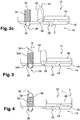
- the figure 3 shows an exemplary embodiment in which the housing 340 over the orifice "OPR" 28 is provided with an opening 341 at its upper end allowing the evacuation of the gas from the reservoir when the pressure within the reservoir leads to the release of the "OPR” orifice 28.
- the chimney 340 is extended by a lower portion 342 to the level of the wall separating the lower chamber 14 and intermediate chamber 16.
- the "OPR” function is in this example completely independent of the "bypass” functions and "SRI", which are insured in the manner explained above. In other words, the "OPR” function bypasses the "bypass” and "ISR" functions.
- the figures 4 and 5 represent an exemplary embodiment in which the "OPR" and "by-pass” functions are combined within a single stack 48.
- This chimney is disposed above the orifice 28.
- the ball 30 closes the orifice “OPR” 28 and is urged by the lower end of a spring 50 disposed in the chimney 48.
- This spring solicits Furthermore, through its upper part, the ball 38 closing the upper orifice 52 of the chimney 48.
- the orifice 52 is normally closed, under the action of the spring 50. In case of depression in the reservoir, the restoring force of the spring 50 on the ball 38 allows this ball to release the orifice 52 and thus let air into the reservoir, as represented by the arrow F on the figure 5 .
- the function "OPR” is provided as described above, thanks to the combined action of the spring 50 and the ball 30.
- the orifice 28 and released under the action of gases they are in the example evacuated via the "ISR" port 44, as represented by the arrow E on the figure 4 .
- the "OPR" orifice is open, the "by-pass” orifice is necessarily closed (and conversely), the gas escaping through the "OPR” orifice can therefore only be evacuated. using the "ISR" port.
- the figure 6 represents an exemplary embodiment of the valve 1, in which the "bypass” orifice 36 is normally closed and in which the "ISR" disk 460 is biased by a return spring 461.
- the operation of the "ISR” disk is analogous to the one explained above, with the difference that the disk 460 is biased towards closing the “ISR” orifice by a return spring 461 disposed in the upper chamber 12, and no longer by its weight alone.
- the disk 460 is therefore in this example not a heavy element.
- the "by-pass” orifice is in the example normally closed, thanks to a spring 420 disposed in the chimney 40, the spring 420 urging the ball 38 towards the closure of the orifice 42 located in the upper part from the chimney 40.
- the invention which is the subject of the present application makes it possible to obtain a compact ventilation system incorporating a large number of functions.
- the implementation of the ventilation system on a tank is limited to mounting a valve according to the invention, a single element, integrated, and easy to assemble.
- the valve according to the invention incorporates almost all the functions that must ensure the ventilation system of a tank, in particular a fuel tank for a motor vehicle. The invention thus makes it possible to obtain a reduction in manufacturing and assembly costs and also to reduce the risk of assembly errors.
Description
La présente invention se rapporte à un système de ventilation de réservoir à liquide, en particulier d'un réservoir à carburant pouvant équiper un véhicule automobile.The present invention relates to a liquid tank ventilation system, in particular a fuel tank that can equip a motor vehicle.
Les réservoirs à liquide, lorsqu'ils sont susceptibles d'être déplacés avec le liquide qu'ils contiennent, sont généralement équipés d'un système de ventilation, également dénommé circuit ou système de mise à l'air. Ce circuit permet l'introduction d'air dans le réservoir en cas de dépression (notamment pour compenser le volume de liquide consommé) et l'évacuation des gaz contenus dans le réservoir en cas de surpression. On garantit ainsi la sécurité par rapport à l'environnement lorsque le réservoir est soumis à des sollicitations diverses : mouvements en tous sens et de toute amplitude, sollicitations thermiques, dépressions et surpressions. Ce circuit permet également de collecter les gaz devant être rejetés dans l'atmosphère pour, dans certains cas, en retirer les composants les plus polluants, en vue de satisfaire les exigences environnementales en la matière, dont la sévérité augmente régulièrement.Liquid tanks, when they can be moved with the liquid they contain, are generally equipped with a ventilation system, also called circuit or venting system. This circuit allows the introduction of air into the tank in case of depression (in particular to compensate for the volume of liquid consumed) and the evacuation of gas contained in the tank in case of overpressure. This guarantees safety relative to the environment when the tank is subjected to various stresses: movements in all directions and of any amplitude, thermal stresses, depressions and overpressures. This circuit also allows to collect the gases to be released into the atmosphere to, in some cases, remove the most polluting components, in order to meet the environmental requirements in the field, whose severity increases steadily.
Les contraintes auxquelles doit répondre le circuit de mise à l'air sont particulièrement sévères dans le cas de réservoirs à carburant montés sur des véhicules automobiles. Il est dans ce cas impératif d'empêcher la sortie de carburant liquide, tout en laissant échapper du gaz, afin de gérer les changements importants de pression et de volume de gaz au cours du ravitaillement du réservoir en carburant et pendant la totalité de la durée du stockage dans le réservoir, y compris durant le roulage du véhicule.The constraints that the venting circuit must meet are particularly severe in the case of fuel tanks mounted on motor vehicles. In this case, it is imperative to prevent the escape of liquid fuel while allowing gas to escape, in order to manage the significant changes in pressure and volume of gas during refueling of the fuel tank and for the duration of the entire duration. storage in the tank, including while driving the vehicle.
Des solutions ont été développées pour répondre à ces contraintes, qui mettent en oeuvre un système de ventilation intégrant notamment un clapet de sécurité plongeant dans le réservoir et dont une partie supérieure traverse une paroi supérieure du réservoir. Alternativement, le clapet peut être disposé intégralement à l'intérieur du réservoir. Un tel clapet est généralement raccordé à un conduit permettant d'évacuer les gaz vers l'atmosphère. Pour certaines applications, un boîtier appelé, canister, est interposé entre le clapet et l'atmosphère, le canister contenant une substance adsorbant les vapeurs de carburant présentes dans les gaz en provenance du réservoir.Solutions have been developed to meet these constraints, which implement a ventilation system including a safety valve dipping into the tank and an upper part through an upper wall of the tank. Alternatively, the valve can be placed entirely inside the tank. Such a valve is generally connected to a conduit for evacuating gases to the atmosphere. For some applications, a housing called canister is interposed between the valve and the atmosphere, the canister containing a substance adsorbing the fuel vapors present in the gas from the tank.
Le système de ventilation peut en outre comporter un ou plusieurs dispositifs pour assurer des fonctions telles que l'interdiction de sur-remplissage lors du ravitaillement en carburant (fonction couramment désignée par l'acronyme « ISR » ou « OFP » pour « Over Filing prévention »), une fonction « by-pass » permettant l'introduction d'air à l'intérieur du réservoir en cas de dépression (notamment lorsque du carburant est consommé), ou encore la fermeture automatique du système de ventilation en cas de retournement du véhicule (fonction couramment désignée par l'acronyme « ROV » pour « Roll-Over-Valve »).The ventilation system may further include one or more devices to provide functions such as prohibition of overfilling during refueling (function commonly referred to by the acronym "ISR" or "OFP" for "Over Filing Prevention""),A" by-pass "function allowing the introduction of air inside the tank in case of depression (especially when fuel is consumed), or still the automatic closing of the ventilation system in case of rollover of the vehicle (function commonly referred to by the acronym "ROV" for "Roll-Over-Valve").
Le système de ventilation peut également intégrer une sécurité anti-surpression, assurant, parallèlement aux autres fonctions (et en particulier en parallèle de la fonction de mise à l'air) une fonction couramment dénommée « OPR » (pour « Over-pressure release »). Cette sécurité est conventionnellement assurée par un clapet disposé à l'extérieur du réservoir, au niveau d'une canalisation de respiration des vapeurs qui relie le ciel du réservoir à une zone de la tubulure de remplissage du réservoir. Cette sécurité doit pouvoir fonctionner lorsque le système de mise à l'air du réservoir est fermé (que ce soit en position normale du réservoir ou en position retournée, lors d'un accident).The ventilation system can also incorporate an anti-overpressure safety device, ensuring, in parallel with the other functions (and in particular in parallel with the breather function), a function commonly referred to as "OPR" (for "Over-pressure release" ). This safety is conventionally provided by a valve disposed outside the tank, at a vapor breathing pipe which connects the tank top to a zone of the filler neck of the tank. This safety must be able to function when the tank venting system is closed (whether in the normal tank position or in the inverted position, during an accident).
D'une manière générale, les progrès accomplis dans le domaine des systèmes de ventilation ont conduit à multiplier les fonctions que ces systèmes peuvent mettre en oeuvre, et donc à la multiplication du nombre et à l'augmentation de la complexité des éléments les constituant. De plus, les divers éléments d'un système de ventilation sont en général reliés entre eux (et, lorsqu'il est prévu, avec le canister) via des tubulures, ce qui augmente les difficultés et le coût d'assemblage ainsi que les risques de mauvais fonctionnement (fuites, canalisation bouchées, etc.)In general, the progress made in the field of ventilation systems has led to a multiplication of the functions that these systems can implement, and therefore to the multiplication of the number and to the increase in the complexity of the elements constituting them. In addition, the various elements of a ventilation system are generally interconnected (and, where provided, with the canister) via tubing, which increases the difficulties and the cost of assembly and the risks malfunction (leaks, blocked pipe, etc.)
Des solutions ont été envisagées pour tenter de faciliter les opérations d'assemblage sur un réservoir en regroupant au maximum les fonctions assurées par le système de ventilation. Ces regroupements nécessitent généralement l'emploi de tubulures et de raccords.Solutions have been envisaged to try to facilitate assembling operations on a tank by grouping at most the functions provided by the ventilation system. These groupings usually require the use of tubing and fittings.
Le document
En outre, les documents
La présente invention vise à améliorer les systèmes de ventilation connus en proposant un clapet de ventilation permettant de limiter au maximum le nombre d'éléments à assembler sur le réservoir, et de réduire les risques d'erreurs de montage ainsi que la quantité de canalisations et de raccordements nécessaires à son bon fonctionnement.The present invention aims to improve the known ventilation systems by providing a ventilation valve to minimize the number of elements to be assembled on the tank, and reduce the risk of assembly errors and the amount of pipes and connections necessary for its proper functioning.
Ainsi, l'invention concerne un clapet de mise à l'air pour réservoir à liquide comportant une enceinte dans laquelle sont intégrés :
- des moyens pour assurer une fonction de fermeture automatique du clapet en cas de retournement du réservoir, ci-après désignée fonction « ROV » ;
- des moyens pour assurer une fonction d'interdiction du remplissage du réservoir au-delà d'un niveau prédéterminé, ci-après désignée fonction « ISR » ;
- des moyens pour permettre de libérer la pression dans le réservoir vers l'atmosphère extérieure en cas de surpression excédant un seuil prédéterminé, ci-après désignée fonction « OPR » ;
- des moyens pour autoriser l'entrée d'air dans le réservoir lorsque la pression régnant au sein du réservoir est inférieure à la pression atmosphérique, ci-après désignée fonction « by-pass » ; caractérisé en ce que ladite fonction « OPR » étant apte à fonctionner lorsque la fonction « ROV » ferme le clapet.
- means for ensuring an automatic closing function of the valve in the event of the tank being turned over, hereinafter referred to as "ROV"function;
- means for providing a function of prohibiting the filling of the tank beyond a predetermined level, hereinafter referred to as "ISR"function;
- means for enabling the pressure in the tank to be released to the outside atmosphere in the event of an overpressure exceeding a predetermined threshold, hereinafter referred to as "OPR"function;
- means for allowing the entry of air into the tank when the pressure prevailing within the tank is below atmospheric pressure, hereinafter referred to as a "bypass"function; characterized in that said function "OPR" being able to function when the function "ROV" closes the valve.
Ainsi, grâce à l'invention, l'implémentation du système de ventilation sur un réservoir se limite au montage d'un clapet tel que défini ci-dessus, soit un élément unique, intégré, et facile à monter. Le clapet conforme à l'invention intègre la quasi-totalité des fonctions que doit assurer le système de ventilation d'un réservoir, en particulier d'un réservoir à carburant pour véhicule automobile. Bien entendu, le clapet selon l'invention est configuré de telle sorte que la fonction « OPR » puisse être mise en oeuvre même lorsque le système de mise à l'air est fermé, tandis que les fonctions ISR et By-pass ne peuvent être mises en oeuvre que lorsque le système de mise à l'air est ouvert.Thus, thanks to the invention, the implementation of the ventilation system on a tank is limited to mounting a valve as defined above, a single element, integrated, and easy to assemble. The valve according to the invention incorporates almost all the functions that must ensure the ventilation system of a tank, in particular a fuel tank for a motor vehicle. Of course, the valve according to the invention is configured in such a way that the "OPR" function can be implemented even when the venting system is closed, while the ISR and bypass functions can not be used. implemented only when the venting system is open.
Dans une réalisation, l'enceinte comprend une chambre supérieure communiquant avec l'atmosphère extérieure, une chambre inférieure communiquant avec l'intérieur du réservoir et une chambre intermédiaire séparant la chambre supérieure et la chambre inférieure.In one embodiment, the enclosure comprises an upper chamber communicating with the outside atmosphere, a lower chamber communicating with the interior of the tank and an intermediate chamber separating the upper chamber and the lower chamber.
Dans une réalisation, les moyens pour assurer la fonction « OPR » comprennent un orifice « OPR », normalement obturé par un élément d'obturation tel qu'une bille, l'élément de fermeture étant soumis à l'action de moyens élastiques tels qu'un ressort.In one embodiment, the means for performing the "OPR" function comprise an "OPR" orifice, normally closed by a closure element such as a ball, the closure element being subjected to the action of elastic means such that 'a spring.
Dans une réalisation, l'orifice « OPR » met en communication la chambre inférieure et la chambre supérieure.In one embodiment, the orifice "OPR" communicates the lower chamber and the upper chamber.
Dans une réalisation, l'orifice « OPR » met en communication la chambre inférieure et la chambre intermédiaire.In one embodiment, the orifice "OPR" communicates the lower chamber and the intermediate chamber.
Dans une réalisation, les moyens pour assurer la fonction « ROV » comprennent un flotteur apte à obturer un orifice « ROV » mettant en communication la chambre inférieure et la chambre intermédiaire.In one embodiment, the means for performing the "ROV" function comprise a float adapted to close a "ROV" orifice placing the lower chamber and the intermediate chamber in communication.
Dans une réalisation, les moyens pour assurer la fonction « ISR » comprennent un élément apte à obturer un orifice « ISR » mettant en communication la chambre intermédiaire et la chambre supérieure.In one embodiment, the means for providing the "ISR" function comprise an element capable of closing an "ISR" orifice placing the intermediate chamber and the upper chamber in communication.
Dans une réalisation, l'élément apte à obturer l'orifice « ISR » est un disque soumis à l'action de son poids propre ou un disque sollicité vers la fermeture de l'orifice par des moyens de rappel élastique tels qu'un ressort.In one embodiment, the element capable of closing the "ISR" orifice is a disc subjected to the action of its own weight or a disc biased towards closing the orifice by elastic return means such as a spring .
Dans une réalisation, les moyens pour assurer la fonction « by-pass » comprennent un orifice « by-pass » apte à mettre en communication la chambre supérieure et la chambre intermédiaire, l'orifice étant obturable par un élément d'obturation tel qu'une bille.In one embodiment, the means for providing the "bypass" function comprise a "by-pass" orifice able to put the upper chamber in communication with the intermediate chamber, the orifice being closable by a closure element such as a ball.
Dans une réalisation, l'élément d'obturation est maintenu en position normale dans sa position de fermeture grâce à l'action de moyens de rappel élastique tels qu'un ressort disposé au sein d'une cheminée communiquant avec l'orifice « by-pass ».In one embodiment, the closure member is held in the normal position in its closed position by the action of elastic return means such as a spring disposed within a chimney communicating with the orifice "by- pass ".
Dans une réalisation, une extrémité de la cheminée est ouverte et met en communication le conduit avec l'atmosphère extérieure, par l'intermédiaire de la chambre supérieure.In one embodiment, one end of the chimney is open and communicates the duct with the outside atmosphere, through the upper chamber.
Dans une réalisation, le clapet comporte un conduit unique au sein duquel sont disposés les moyens by-pass et les moyens OPR, ledit conduit comportant deux éléments d'obturation, tels que des billes, sollicités par un ressort.In one embodiment, the valve comprises a single conduit in which are disposed the bypass means and the OPR means, said conduit having two closure elements, such as balls, biased by a spring.
L'invention sera mieux comprise à la lecture de la description qui va suivre, donnée uniquement à titre d'exemple et faite en se référant aux dessins dans lesquels :
- les
figures 1, 2A, 2B et2C montrent un premier exemple de réalisation d'un clapet conforme à l'invention ; - les
figures 3 et 4 montrent un deuxième exemple de réalisation d'un clapet conforme à l'invention ; - la
figure 5 montre un troisième exemple de réalisation d'un clapet conforme à l'invention ; - la
figure 6 montre un quatrième exemple de réalisation d'un clapet conforme à l'invention.
- the
Figures 1, 2A, 2B and2C show a first embodiment of a valve according to the invention; - the
Figures 3 and 4 show a second embodiment of a valve according to the invention; - the
figure 5 shows a third embodiment of a valve according to the invention; - the
figure 6 shows a fourth embodiment of a valve according to the invention.
La
Lorsque le clapet 1 est positionné sur un réservoir, au niveau d'une paroi supérieure 2 du réservoir (partiellement représentée sur la
Dans une partie supérieure 18 de l'enceinte 10, le clapet 1 est pourvu d'un conduit 20 mettant en communication la chambre supérieure 12 et l'atmosphère extérieure, éventuellement par l'intermédiaire d'un canister (non représenté).In an
La chambre inférieure 14 est pourvue d'un flotteur 22, pourvu d'un pointeau 24 apte à venir obturer un premier orifice, ou orifice « ROV » 26 mettant en communication la chambre inférieure 14 et la chambre intermédiaire 16. Lorsque l'orifice « ROV » est fermé, tout passage de gaz ou de liquide entre la chambre inférieure 14 et la chambre supérieure 16 est interdit. Comme la chambre inférieure 14 est en communication avec l'intérieur du réservoir, le flotteur est apte à obturer l'orifice 26 par l'intermédiaire du pointeau 24 lorsque le niveau de carburant devient suffisamment élevé dans le réservoir, empêchant ainsi la sortie des gaz. Afin d'assurer la fonction « ROV », une bille dense (non représentée) reposant dans un puits ajouré (non représenté) est disposé sous le flotteur. Cette bille a pour fonction d'entrainer le flotteur 22 vers le haut lorsque le réservoir amorce un mouvement de retournement, au-delà d'une valeur d'angle de rotation prédéterminée, par exemple 80 degrés.The
Un deuxième orifice, ou orifice « OPR » 28 est disposé entre la chambre inférieure 14 et la chambre intermédiaire 16. Cet orifice est normalement fermé par une bille 30 sollicité vers la fermeture de l'orifice « OPR » 28 par des moyens élastiques tels qu'un ressort 32. La bille 30 et le ressort 32 sont disposés dans un logement 34. L'ensemble formé par l'orifice « OPR » 28, et les moyens de fermeture de cet orifice qui comprennent la bille 30 et le ressort 32 permettent d'assurer une fonction « OPR », c'est-à-dire permettre l'échappement de gaz vers l'atmosphère extérieure en cas de surpression excédant un seuil prédéterminé. Les éléments tels que le ressort 32, la bille 30 (ou encore le siège sur lequel repose la bille 30) seront déterminés et dimensionnés de sorte que l'orifice « OPR » sera libéré si la pression dans le réservoir atteint ou dépasse le seuil de pression prédéterminé. En particulier, cette fonction assurera la sécurité voulue pour le réservoir à carburant dans le cas où l'orifice « ROV » 26 serait maintenu obstrué par le flotteur 22 durant un laps de temps important (par exemple dans le cas d'un blocage du flotteur en position haute, que ce blocage soit consécutif à un retournement du réservoir ou non), empêchant ainsi l'évacuation normale des gaz via l'orifice « ROV » 26.A second orifice or orifice "OPR" 28 is disposed between the
Dans l'exemple des
Afin de permettre au gaz provenant de la chambre intermédiaire 16 de transiter vers la chambre supérieure, sont prévus deux orifices.In order to allow gas from the
Le premier de ces deux orifices, ou orifice « by-pass » 36, a pour fonction première de permettre le passage d'air vers le réservoir, lorsque la pression régnant dans le réservoir est inférieure à la pression atmosphérique (notamment en cas de consommation de carburant lors du fonctionnement du véhicule). Dans l'exemple de la
Comme représenté sur la
Le deuxième orifice permettant l'évacuation des gaz est l'orifice « ISR » 44, mettant en communication la chambre intermédiaire 16 et la chambre supérieure 12, et apte à être obturé par un élément sollicité vers la fermeture de l'orifice « ISR » 44 sous l'action de son propre poids. Dans l'exemple des
Avantageusement, les dispositifs assurant les fonctions « by-pass » et « ISR » seront conçus et dimensionnés pour coordonner l'ouverture des orifices « by-pass » et « ISR. ». Ainsi, on peut par exemple envisager que l'orifice « by-pass », qui est dans l'exemple normalement ouvert, permette (toujours dans le cas où l'orifice « OPR » est ouvert) l'évacuation des gaz jusqu'à un différentiel de pression entre l'intérieur du réservoir et l'atmosphère extérieure prédéterminé, puis, qu'au-delà de ce seuil, l'orifice «by-pass » étant fermé par la remontée de la bille 38 dans la cheminée 40, la pression des gaz et le débit en résultant permette de soulever le disque « ISR » 46. Dans un tel cas, l'évacuation des gaz ne se fait pas simultanément selon les trajets correspondants respectivement aux flèches A et B, mais séquentiellement en cas de montée en pression à l'intérieur du réservoir (initialement selon la flèche A puis par la flèche B uniquement) comme visible sur les
La
Les
Dans l'exemple des
La
L'invention objet de la présente demande permet d'obtenir un système de ventilation compact, intégrant un nombre de fonctions important. Ainsi, grâce à l'invention, l'implémentation du système de ventilation sur un réservoir se limite au montage d'un clapet conforme à l'invention, soit un élément unique, intégré, et facile à monter. Le clapet conforme à l'invention intègre la quasi-totalité des fonctions que doit assurer le système de ventilation d'un réservoir, en particulier d'un réservoir à carburant pour véhicule automobile. L'invention permet ainsi d'obtenir une réduction des coûts de fabrication et d'assemblage et également de diminuer les risques d'erreur de montage.The invention which is the subject of the present application makes it possible to obtain a compact ventilation system incorporating a large number of functions. Thus, thanks to the invention, the implementation of the ventilation system on a tank is limited to mounting a valve according to the invention, a single element, integrated, and easy to assemble. The valve according to the invention incorporates almost all the functions that must ensure the ventilation system of a tank, in particular a fuel tank for a motor vehicle. The invention thus makes it possible to obtain a reduction in manufacturing and assembly costs and also to reduce the risk of assembly errors.
Claims (12)
- Vent valve (1) for a liquid tank comprising an enclosed space (10) incorporating:- means (22, 24, 26) for performing a function of automatically closing the valve if the tank rolls over, hereinafter referred to as the "ROV" function;- means (44, 46) for performing a function of preventing the tank from being filled beyond a predetermined level, hereinafter referred to as the "ISR" function;- means (28, 30, 32) for allowing the release of pressure in the tank to the external atmosphere in the event of an overpressure exceeding a predetermined threshold, hereinafter referred to as the "OPR" function;- means (36, 38, 40, 42) for allowing air to enter the tank when the pressure obtaining in the tank is below atmospheric pressure, hereinafter referred to as the "bypass" function.characterized in that the said "OPR" function being able to operate when the "ROV" function closes the valve (1).
- Valve according to Claim 1, in which the enclosed space (10) comprises an upper chamber (12) communicating with the external atmosphere, a lower chamber (14) communicating with the inside of the tank and an intermediate chamber (16) separating the upper chamber (12) and the lower chamber (14).
- Valve according to one of the preceding claims, in which the means for performing the "OPR" function comprise an "OPR" orifice (28), normally closed by a shutoff element such as a ball (30), the closure element being subjected to the action of elastic means such as a spring (32).
- Valve according to the preceding claim depending on Claim 2, in which the "OPR" orifice places the lower chamber (14) and the upper chamber (12) in communication.
- Valve according to Claim 3 depending on Claim 2, in which the "OPR" orifice places the lower chamber (14) and the intermediate chamber (16) in communication.
- Valve according to one of the preceding claims, in which the means for performing the "ROV" function comprise a float (22) able to shut off an "ROV" orifice (26) placing the lower chamber (14) and the intermediate chamber (16) in communication.
- Valve according to one of the preceding claims depending on Claim 2, in which the means for performing the "ISR" function comprise an element (46; 460) able to shut off an "ISR" orifice (44) placing the intermediate chamber (16) and the upper chamber (12) in communication.
- Valve according to the preceding claim, in which the element able to shut off the "ISR" orifice (44) is a disk (46) subjected to the action of its own weight or a disk (460) urged toward the closing of the "ISR" orifice (44) by elastic return means such as a spring (461) .
- Valve according to one of the preceding claims depending on Claim 2, in which the means for performing the "bypass" function comprise a "bypass" orifice (36) able to place the upper chamber (12) and the intermediate chamber (16) in communication, the orifice being able to be shut off by a shutoff element (38) such as a ball.
- Valve according to the preceding claim, in which the shutoff element (38) is kept in the normal position in its position of closure by virtue of the action of elastic return means such as a spring arranged inside a vent (40) communicating with the "bypass" orifice.
- Valve according to Claim 10, in which one end (42) of the vent (40) is open and places the pipe in communication with the external atmosphere, via the upper chamber (12).
- Valve according to one of Claims 10 and 11 in combination with Claim 3, comprising a single pipe (48) within which the bypass means and the OPR means are arranged, said pipe comprising two shutoff elements (30, 38) such as balls urged by a spring (50).
Applications Claiming Priority (2)
| Application Number | Priority Date | Filing Date | Title |
|---|---|---|---|
| FR1259241A FR2996279B1 (en) | 2012-09-28 | 2012-09-28 | VENTILATION VALVE FOR A LIQUID RESERVOIR INCLUDING ANTI-PRESSURE SAFETY. |
| PCT/IB2013/059013 WO2014049584A2 (en) | 2012-09-28 | 2013-09-30 | Vent valve for liquid tank incorporating anti-overpressure safety feature |
Publications (2)
| Publication Number | Publication Date |
|---|---|
| EP2901057A2 EP2901057A2 (en) | 2015-08-05 |
| EP2901057B1 true EP2901057B1 (en) | 2018-03-21 |
Family
ID=47257984
Family Applications (1)
| Application Number | Title | Priority Date | Filing Date |
|---|---|---|---|
| EP13792755.4A Active EP2901057B1 (en) | 2012-09-28 | 2013-09-30 | Vent valve for liquid tank incorporating anti-overpressure safety feature |
Country Status (5)
| Country | Link |
|---|---|
| EP (1) | EP2901057B1 (en) |
| JP (2) | JP2015535770A (en) |
| CN (1) | CN104685277B (en) |
| FR (1) | FR2996279B1 (en) |
| WO (1) | WO2014049584A2 (en) |
Families Citing this family (2)
| Publication number | Priority date | Publication date | Assignee | Title |
|---|---|---|---|---|
| DE102014106468A1 (en) * | 2014-05-08 | 2015-11-12 | Alfred Kärcher Gmbh & Co. Kg | Steam cleaner |
| FR3044612B1 (en) * | 2015-12-07 | 2019-08-23 | Continental Automotive France | CONTROL OF DEPRESSURIZATION OF A FUEL TANK OF A MOTOR VEHICLE |
Citations (6)
| Publication number | Priority date | Publication date | Assignee | Title |
|---|---|---|---|---|
| US5582198A (en) * | 1994-04-28 | 1996-12-10 | Toyoda Gosei Co., Ltd. | Bidirectional valve and fuel shut-off device |
| US5666989A (en) * | 1994-11-08 | 1997-09-16 | Stant Manufacturing Inc. | Tank venting control assembly |
| FR2766134A1 (en) * | 1997-07-18 | 1999-01-22 | Journee Paul Sa | Safety air inlet for vehicle fuel tank |
| US20030062083A1 (en) * | 2001-09-28 | 2003-04-03 | Hiroshi Nishi | Fuel cutoff valve |
| FR2896568A1 (en) * | 2006-01-26 | 2007-07-27 | Inergy Automotive Systems Res | Flow management valve for ventilation valve, has shutter moving in conical part of control chamber between operation and filling positions, where chamber communicates with interior of liquid reservoir, filling head and canister |
| US20100282335A1 (en) * | 2009-05-11 | 2010-11-11 | Eaton Corporation | Fuel vapor vent valve with dynamic pressure relief |
Family Cites Families (3)
| Publication number | Priority date | Publication date | Assignee | Title |
|---|---|---|---|---|
| JP4078134B2 (en) * | 2002-07-02 | 2008-04-23 | 株式会社ニフコ | Integrated valve for fuel tank |
| JP4924330B2 (en) * | 2007-09-27 | 2012-04-25 | 豊田合成株式会社 | Fuel shut-off valve |
| CN201568619U (en) * | 2009-08-31 | 2010-09-01 | 中国人民解放军62153部队 | Automatic scavenging air valve for oil tank |
-
2012
- 2012-09-28 FR FR1259241A patent/FR2996279B1/en not_active Expired - Fee Related
-
2013
- 2013-09-30 CN CN201380049998.8A patent/CN104685277B/en active Active
- 2013-09-30 EP EP13792755.4A patent/EP2901057B1/en active Active
- 2013-09-30 JP JP2015533751A patent/JP2015535770A/en active Pending
- 2013-09-30 WO PCT/IB2013/059013 patent/WO2014049584A2/en active Application Filing
-
2018
- 2018-07-19 JP JP2018135760A patent/JP2018165151A/en active Pending
Patent Citations (6)
| Publication number | Priority date | Publication date | Assignee | Title |
|---|---|---|---|---|
| US5582198A (en) * | 1994-04-28 | 1996-12-10 | Toyoda Gosei Co., Ltd. | Bidirectional valve and fuel shut-off device |
| US5666989A (en) * | 1994-11-08 | 1997-09-16 | Stant Manufacturing Inc. | Tank venting control assembly |
| FR2766134A1 (en) * | 1997-07-18 | 1999-01-22 | Journee Paul Sa | Safety air inlet for vehicle fuel tank |
| US20030062083A1 (en) * | 2001-09-28 | 2003-04-03 | Hiroshi Nishi | Fuel cutoff valve |
| FR2896568A1 (en) * | 2006-01-26 | 2007-07-27 | Inergy Automotive Systems Res | Flow management valve for ventilation valve, has shutter moving in conical part of control chamber between operation and filling positions, where chamber communicates with interior of liquid reservoir, filling head and canister |
| US20100282335A1 (en) * | 2009-05-11 | 2010-11-11 | Eaton Corporation | Fuel vapor vent valve with dynamic pressure relief |
Also Published As
| Publication number | Publication date |
|---|---|
| CN104685277A (en) | 2015-06-03 |
| WO2014049584A2 (en) | 2014-04-03 |
| FR2996279A1 (en) | 2014-04-04 |
| EP2901057A2 (en) | 2015-08-05 |
| CN104685277B (en) | 2018-05-15 |
| FR2996279B1 (en) | 2015-07-03 |
| WO2014049584A3 (en) | 2014-06-12 |
| JP2015535770A (en) | 2015-12-17 |
| JP2018165151A (en) | 2018-10-25 |
Similar Documents
| Publication | Publication Date | Title |
|---|---|---|
| EP1172306B1 (en) | Venting system for liquid tank | |
| US4630749A (en) | Fuel fill tube with vapor vent and overfill protection | |
| WO1999042318A1 (en) | Fuel tank equipped with a gas evacuating system | |
| WO2007085309A1 (en) | Valve for air venting circuit for a liquid tank | |
| FR2886367A1 (en) | VALVE FOR AIR FLOW CIRCUIT OF A LIQUID TANK | |
| FR2770464A1 (en) | APPARATUS FOR CONTROLLING VAPORS OF A FUEL TANK | |
| BE1012697A3 (en) | Fuel tank. | |
| EP0943476B1 (en) | Venting circuit for fluid reservoir | |
| FR2739612A1 (en) | APPARATUS FOR CONTROLLING FUEL TANK VESSELS IN A VEHICLE | |
| FR2877650A1 (en) | TANK VENTILATION DEVICE | |
| BE1012992A3 (en) | Safety valve for liquid tank. | |
| WO2005106301A1 (en) | Internal tank gas pressure control valve | |
| EP2901057B1 (en) | Vent valve for liquid tank incorporating anti-overpressure safety feature | |
| EP1552776B1 (en) | Pressure cooker provided with a security valve made of elastomeric material | |
| JP6625117B2 (en) | Fuel tank assembly with trigger vent | |
| FR2954805A1 (en) | VALVE FOR AIR FLOW CIRCUIT OF A LIQUID TANK | |
| EP0774372B1 (en) | Improved venting device for fuel tank for motor vehicle and fuel tank including this device | |
| EP0459866B1 (en) | Device for the ventilation of a fuel tank | |
| FR2905745A1 (en) | Fuel e.g. petrol, tank`s venting system for motor vehicle, has check valve forced in closed position of opening by float at level of fuel, where float straightens arm and support to stop deformation of valve when level attains certain limit | |
| EP0545789A1 (en) | Expansion tank for a boiling liquid cooling circuit | |
| EP0516528B1 (en) | Safety valve for the ventilation of a fuel tank of a motor vehicle | |
| FR2669864A1 (en) | Vent valve for a vehicle fuel tank | |
| FR3069197A1 (en) | VENTILATION DEVICE FOR A VEHICLE LIQUID RESERVOIR | |
| FR2766134A1 (en) | Safety air inlet for vehicle fuel tank | |
| FR2774636A1 (en) | Connection of automobile fuel tank to atmosphere to release tank over pressure |
Legal Events
| Date | Code | Title | Description |
|---|---|---|---|
| PUAI | Public reference made under article 153(3) epc to a published international application that has entered the european phase |
Free format text: ORIGINAL CODE: 0009012 |
|
| 17P | Request for examination filed |
Effective date: 20150408 |
|
| AK | Designated contracting states |
Kind code of ref document: A2 Designated state(s): AL AT BE BG CH CY CZ DE DK EE ES FI FR GB GR HR HU IE IS IT LI LT LU LV MC MK MT NL NO PL PT RO RS SE SI SK SM TR |
|
| AX | Request for extension of the european patent |
Extension state: BA ME |
|
| DAX | Request for extension of the european patent (deleted) | ||
| PUAG | Search results despatched under rule 164(2) epc together with communication from examining division |
Free format text: ORIGINAL CODE: 0009017 |
|
| 17Q | First examination report despatched |
Effective date: 20160830 |
|
| B565 | Issuance of search results under rule 164(2) epc |
Effective date: 20160830 |
|
| GRAP | Despatch of communication of intention to grant a patent |
Free format text: ORIGINAL CODE: EPIDOSNIGR1 |
|
| INTG | Intention to grant announced |
Effective date: 20170712 |
|
| GRAJ | Information related to disapproval of communication of intention to grant by the applicant or resumption of examination proceedings by the epo deleted |
Free format text: ORIGINAL CODE: EPIDOSDIGR1 |
|
| GRAP | Despatch of communication of intention to grant a patent |
Free format text: ORIGINAL CODE: EPIDOSNIGR1 |
|
| INTC | Intention to grant announced (deleted) | ||
| INTG | Intention to grant announced |
Effective date: 20171018 |
|
| GRAS | Grant fee paid |
Free format text: ORIGINAL CODE: EPIDOSNIGR3 |
|
| GRAA | (expected) grant |
Free format text: ORIGINAL CODE: 0009210 |
|
| RAP1 | Party data changed (applicant data changed or rights of an application transferred) |
Owner name: PLASTIC OMNIUM ADVANCED INNOVATION AND RESEARCH |
|
| AK | Designated contracting states |
Kind code of ref document: B1 Designated state(s): AL AT BE BG CH CY CZ DE DK EE ES FI FR GB GR HR HU IE IS IT LI LT LU LV MC MK MT NL NO PL PT RO RS SE SI SK SM TR |
|
| REG | Reference to a national code |
Ref country code: GB Ref legal event code: FG4D Free format text: NOT ENGLISH |
|
| REG | Reference to a national code |
Ref country code: CH Ref legal event code: EP |
|
| REG | Reference to a national code |
Ref country code: AT Ref legal event code: REF Ref document number: 981469 Country of ref document: AT Kind code of ref document: T Effective date: 20180415 |
|
| REG | Reference to a national code |
Ref country code: IE Ref legal event code: FG4D Free format text: LANGUAGE OF EP DOCUMENT: FRENCH |
|
| REG | Reference to a national code |
Ref country code: DE Ref legal event code: R096 Ref document number: 602013034765 Country of ref document: DE |
|
| REG | Reference to a national code |
Ref country code: NL Ref legal event code: MP Effective date: 20180321 |
|
| PG25 | Lapsed in a contracting state [announced via postgrant information from national office to epo] |
Ref country code: HR Free format text: LAPSE BECAUSE OF FAILURE TO SUBMIT A TRANSLATION OF THE DESCRIPTION OR TO PAY THE FEE WITHIN THE PRESCRIBED TIME-LIMIT Effective date: 20180321 Ref country code: FI Free format text: LAPSE BECAUSE OF FAILURE TO SUBMIT A TRANSLATION OF THE DESCRIPTION OR TO PAY THE FEE WITHIN THE PRESCRIBED TIME-LIMIT Effective date: 20180321 Ref country code: NO Free format text: LAPSE BECAUSE OF FAILURE TO SUBMIT A TRANSLATION OF THE DESCRIPTION OR TO PAY THE FEE WITHIN THE PRESCRIBED TIME-LIMIT Effective date: 20180621 Ref country code: LT Free format text: LAPSE BECAUSE OF FAILURE TO SUBMIT A TRANSLATION OF THE DESCRIPTION OR TO PAY THE FEE WITHIN THE PRESCRIBED TIME-LIMIT Effective date: 20180321 Ref country code: CY Free format text: LAPSE BECAUSE OF FAILURE TO SUBMIT A TRANSLATION OF THE DESCRIPTION OR TO PAY THE FEE WITHIN THE PRESCRIBED TIME-LIMIT Effective date: 20180321 |
|
| REG | Reference to a national code |
Ref country code: LT Ref legal event code: MG4D |
|
| REG | Reference to a national code |
Ref country code: AT Ref legal event code: MK05 Ref document number: 981469 Country of ref document: AT Kind code of ref document: T Effective date: 20180321 |
|
| PG25 | Lapsed in a contracting state [announced via postgrant information from national office to epo] |
Ref country code: SE Free format text: LAPSE BECAUSE OF FAILURE TO SUBMIT A TRANSLATION OF THE DESCRIPTION OR TO PAY THE FEE WITHIN THE PRESCRIBED TIME-LIMIT Effective date: 20180321 Ref country code: LV Free format text: LAPSE BECAUSE OF FAILURE TO SUBMIT A TRANSLATION OF THE DESCRIPTION OR TO PAY THE FEE WITHIN THE PRESCRIBED TIME-LIMIT Effective date: 20180321 Ref country code: GR Free format text: LAPSE BECAUSE OF FAILURE TO SUBMIT A TRANSLATION OF THE DESCRIPTION OR TO PAY THE FEE WITHIN THE PRESCRIBED TIME-LIMIT Effective date: 20180622 Ref country code: RS Free format text: LAPSE BECAUSE OF FAILURE TO SUBMIT A TRANSLATION OF THE DESCRIPTION OR TO PAY THE FEE WITHIN THE PRESCRIBED TIME-LIMIT Effective date: 20180321 Ref country code: BG Free format text: LAPSE BECAUSE OF FAILURE TO SUBMIT A TRANSLATION OF THE DESCRIPTION OR TO PAY THE FEE WITHIN THE PRESCRIBED TIME-LIMIT Effective date: 20180621 |
|
| REG | Reference to a national code |
Ref country code: FR Ref legal event code: PLFP Year of fee payment: 6 |
|
| PG25 | Lapsed in a contracting state [announced via postgrant information from national office to epo] |
Ref country code: MT Free format text: LAPSE BECAUSE OF FAILURE TO SUBMIT A TRANSLATION OF THE DESCRIPTION OR TO PAY THE FEE WITHIN THE PRESCRIBED TIME-LIMIT Effective date: 20180321 |
|
| PG25 | Lapsed in a contracting state [announced via postgrant information from national office to epo] |
Ref country code: RO Free format text: LAPSE BECAUSE OF FAILURE TO SUBMIT A TRANSLATION OF THE DESCRIPTION OR TO PAY THE FEE WITHIN THE PRESCRIBED TIME-LIMIT Effective date: 20180321 Ref country code: IT Free format text: LAPSE BECAUSE OF FAILURE TO SUBMIT A TRANSLATION OF THE DESCRIPTION OR TO PAY THE FEE WITHIN THE PRESCRIBED TIME-LIMIT Effective date: 20180321 Ref country code: AL Free format text: LAPSE BECAUSE OF FAILURE TO SUBMIT A TRANSLATION OF THE DESCRIPTION OR TO PAY THE FEE WITHIN THE PRESCRIBED TIME-LIMIT Effective date: 20180321 Ref country code: NL Free format text: LAPSE BECAUSE OF FAILURE TO SUBMIT A TRANSLATION OF THE DESCRIPTION OR TO PAY THE FEE WITHIN THE PRESCRIBED TIME-LIMIT Effective date: 20180321 Ref country code: PL Free format text: LAPSE BECAUSE OF FAILURE TO SUBMIT A TRANSLATION OF THE DESCRIPTION OR TO PAY THE FEE WITHIN THE PRESCRIBED TIME-LIMIT Effective date: 20180321 Ref country code: EE Free format text: LAPSE BECAUSE OF FAILURE TO SUBMIT A TRANSLATION OF THE DESCRIPTION OR TO PAY THE FEE WITHIN THE PRESCRIBED TIME-LIMIT Effective date: 20180321 Ref country code: ES Free format text: LAPSE BECAUSE OF FAILURE TO SUBMIT A TRANSLATION OF THE DESCRIPTION OR TO PAY THE FEE WITHIN THE PRESCRIBED TIME-LIMIT Effective date: 20180321 |
|
| PG25 | Lapsed in a contracting state [announced via postgrant information from national office to epo] |
Ref country code: SM Free format text: LAPSE BECAUSE OF FAILURE TO SUBMIT A TRANSLATION OF THE DESCRIPTION OR TO PAY THE FEE WITHIN THE PRESCRIBED TIME-LIMIT Effective date: 20180321 Ref country code: AT Free format text: LAPSE BECAUSE OF FAILURE TO SUBMIT A TRANSLATION OF THE DESCRIPTION OR TO PAY THE FEE WITHIN THE PRESCRIBED TIME-LIMIT Effective date: 20180321 Ref country code: CZ Free format text: LAPSE BECAUSE OF FAILURE TO SUBMIT A TRANSLATION OF THE DESCRIPTION OR TO PAY THE FEE WITHIN THE PRESCRIBED TIME-LIMIT Effective date: 20180321 Ref country code: SK Free format text: LAPSE BECAUSE OF FAILURE TO SUBMIT A TRANSLATION OF THE DESCRIPTION OR TO PAY THE FEE WITHIN THE PRESCRIBED TIME-LIMIT Effective date: 20180321 |
|
| PG25 | Lapsed in a contracting state [announced via postgrant information from national office to epo] |
Ref country code: PT Free format text: LAPSE BECAUSE OF FAILURE TO SUBMIT A TRANSLATION OF THE DESCRIPTION OR TO PAY THE FEE WITHIN THE PRESCRIBED TIME-LIMIT Effective date: 20180723 |
|
| REG | Reference to a national code |
Ref country code: DE Ref legal event code: R097 Ref document number: 602013034765 Country of ref document: DE |
|
| PLBE | No opposition filed within time limit |
Free format text: ORIGINAL CODE: 0009261 |
|
| STAA | Information on the status of an ep patent application or granted ep patent |
Free format text: STATUS: NO OPPOSITION FILED WITHIN TIME LIMIT |
|
| PG25 | Lapsed in a contracting state [announced via postgrant information from national office to epo] |
Ref country code: DK Free format text: LAPSE BECAUSE OF FAILURE TO SUBMIT A TRANSLATION OF THE DESCRIPTION OR TO PAY THE FEE WITHIN THE PRESCRIBED TIME-LIMIT Effective date: 20180321 |
|
| 26N | No opposition filed |
Effective date: 20190102 |
|
| REG | Reference to a national code |
Ref country code: DE Ref legal event code: R119 Ref document number: 602013034765 Country of ref document: DE |
|
| PG25 | Lapsed in a contracting state [announced via postgrant information from national office to epo] |
Ref country code: MC Free format text: LAPSE BECAUSE OF FAILURE TO SUBMIT A TRANSLATION OF THE DESCRIPTION OR TO PAY THE FEE WITHIN THE PRESCRIBED TIME-LIMIT Effective date: 20180321 |
|
| REG | Reference to a national code |
Ref country code: CH Ref legal event code: PL |
|
| GBPC | Gb: european patent ceased through non-payment of renewal fee |
Effective date: 20180930 |
|
| PG25 | Lapsed in a contracting state [announced via postgrant information from national office to epo] |
Ref country code: SI Free format text: LAPSE BECAUSE OF FAILURE TO SUBMIT A TRANSLATION OF THE DESCRIPTION OR TO PAY THE FEE WITHIN THE PRESCRIBED TIME-LIMIT Effective date: 20180321 |
|
| REG | Reference to a national code |
Ref country code: BE Ref legal event code: MM Effective date: 20180930 |
|
| REG | Reference to a national code |
Ref country code: IE Ref legal event code: MM4A |
|
| PG25 | Lapsed in a contracting state [announced via postgrant information from national office to epo] |
Ref country code: LU Free format text: LAPSE BECAUSE OF NON-PAYMENT OF DUE FEES Effective date: 20180930 |
|
| PG25 | Lapsed in a contracting state [announced via postgrant information from national office to epo] |
Ref country code: IE Free format text: LAPSE BECAUSE OF NON-PAYMENT OF DUE FEES Effective date: 20180930 Ref country code: DE Free format text: LAPSE BECAUSE OF NON-PAYMENT OF DUE FEES Effective date: 20190402 |
|
| PG25 | Lapsed in a contracting state [announced via postgrant information from national office to epo] |
Ref country code: BE Free format text: LAPSE BECAUSE OF NON-PAYMENT OF DUE FEES Effective date: 20180930 Ref country code: CH Free format text: LAPSE BECAUSE OF NON-PAYMENT OF DUE FEES Effective date: 20180930 Ref country code: LI Free format text: LAPSE BECAUSE OF NON-PAYMENT OF DUE FEES Effective date: 20180930 |
|
| PG25 | Lapsed in a contracting state [announced via postgrant information from national office to epo] |
Ref country code: GB Free format text: LAPSE BECAUSE OF NON-PAYMENT OF DUE FEES Effective date: 20180930 |
|
| PG25 | Lapsed in a contracting state [announced via postgrant information from national office to epo] |
Ref country code: TR Free format text: LAPSE BECAUSE OF FAILURE TO SUBMIT A TRANSLATION OF THE DESCRIPTION OR TO PAY THE FEE WITHIN THE PRESCRIBED TIME-LIMIT Effective date: 20180321 |
|
| PG25 | Lapsed in a contracting state [announced via postgrant information from national office to epo] |
Ref country code: MK Free format text: LAPSE BECAUSE OF NON-PAYMENT OF DUE FEES Effective date: 20180321 Ref country code: HU Free format text: LAPSE BECAUSE OF FAILURE TO SUBMIT A TRANSLATION OF THE DESCRIPTION OR TO PAY THE FEE WITHIN THE PRESCRIBED TIME-LIMIT; INVALID AB INITIO Effective date: 20130930 |
|
| PG25 | Lapsed in a contracting state [announced via postgrant information from national office to epo] |
Ref country code: IS Free format text: LAPSE BECAUSE OF FAILURE TO SUBMIT A TRANSLATION OF THE DESCRIPTION OR TO PAY THE FEE WITHIN THE PRESCRIBED TIME-LIMIT Effective date: 20180721 |
|
| P01 | Opt-out of the competence of the unified patent court (upc) registered |
Effective date: 20230515 |
|
| PGFP | Annual fee paid to national office [announced via postgrant information from national office to epo] |
Ref country code: FR Payment date: 20230929 Year of fee payment: 11 |