EP2901014B1 - Hydraulic apparatus having an improved structure for the cylinder implementation thereof - Google Patents
Hydraulic apparatus having an improved structure for the cylinder implementation thereof Download PDFInfo
- Publication number
- EP2901014B1 EP2901014B1 EP13766504.8A EP13766504A EP2901014B1 EP 2901014 B1 EP2901014 B1 EP 2901014B1 EP 13766504 A EP13766504 A EP 13766504A EP 2901014 B1 EP2901014 B1 EP 2901014B1
- Authority
- EP
- European Patent Office
- Prior art keywords
- cylinder block
- hydraulic
- rotation
- distributor
- hydraulic apparatus
- Prior art date
- Legal status (The legal status is an assumption and is not a legal conclusion. Google has not performed a legal analysis and makes no representation as to the accuracy of the status listed.)
- Active
Links
- 238000006073 displacement reaction Methods 0.000 claims description 33
- 230000000712 assembly Effects 0.000 claims description 25
- 238000000429 assembly Methods 0.000 claims description 25
- 230000000694 effects Effects 0.000 claims description 12
- 238000000034 method Methods 0.000 claims description 5
- 238000010168 coupling process Methods 0.000 claims description 4
- 238000005859 coupling reaction Methods 0.000 claims description 4
- 230000004913 activation Effects 0.000 claims description 3
- 239000012530 fluid Substances 0.000 description 15
- 238000007789 sealing Methods 0.000 description 8
- 230000000750 progressive effect Effects 0.000 description 7
- 230000005540 biological transmission Effects 0.000 description 6
- 230000000295 complement effect Effects 0.000 description 6
- 230000036961 partial effect Effects 0.000 description 6
- 238000012423 maintenance Methods 0.000 description 4
- 230000000284 resting effect Effects 0.000 description 4
- 238000013519 translation Methods 0.000 description 4
- 238000007667 floating Methods 0.000 description 3
- 230000003068 static effect Effects 0.000 description 3
- 230000001360 synchronised effect Effects 0.000 description 3
- 230000006835 compression Effects 0.000 description 2
- 238000007906 compression Methods 0.000 description 2
- 238000010586 diagram Methods 0.000 description 2
- 230000010354 integration Effects 0.000 description 2
- 230000002093 peripheral effect Effects 0.000 description 2
- 238000011084 recovery Methods 0.000 description 2
- 230000002829 reductive effect Effects 0.000 description 2
- 230000002441 reversible effect Effects 0.000 description 2
- 230000035939 shock Effects 0.000 description 2
- 230000009471 action Effects 0.000 description 1
- 238000013459 approach Methods 0.000 description 1
- 210000000078 claw Anatomy 0.000 description 1
- 230000002301 combined effect Effects 0.000 description 1
- 238000002485 combustion reaction Methods 0.000 description 1
- 238000010276 construction Methods 0.000 description 1
- 238000007599 discharging Methods 0.000 description 1
- 230000003100 immobilizing effect Effects 0.000 description 1
- 230000000670 limiting effect Effects 0.000 description 1
- 230000014759 maintenance of location Effects 0.000 description 1
- 230000009467 reduction Effects 0.000 description 1
- 238000012549 training Methods 0.000 description 1
- 230000007704 transition Effects 0.000 description 1
Images


Classifications
-
- F—MECHANICAL ENGINEERING; LIGHTING; HEATING; WEAPONS; BLASTING
- F04—POSITIVE - DISPLACEMENT MACHINES FOR LIQUIDS; PUMPS FOR LIQUIDS OR ELASTIC FLUIDS
- F04B—POSITIVE-DISPLACEMENT MACHINES FOR LIQUIDS; PUMPS
- F04B1/00—Multi-cylinder machines or pumps characterised by number or arrangement of cylinders
- F04B1/04—Multi-cylinder machines or pumps characterised by number or arrangement of cylinders having cylinders in star- or fan-arrangement
- F04B1/0404—Details or component parts
- F04B1/0426—Arrangements for pressing the pistons against the actuated cam; Arrangements for connecting the pistons to the actuated cam
-
- F—MECHANICAL ENGINEERING; LIGHTING; HEATING; WEAPONS; BLASTING
- F01—MACHINES OR ENGINES IN GENERAL; ENGINE PLANTS IN GENERAL; STEAM ENGINES
- F01B—MACHINES OR ENGINES, IN GENERAL OR OF POSITIVE-DISPLACEMENT TYPE, e.g. STEAM ENGINES
- F01B3/00—Reciprocating-piston machines or engines with cylinder axes coaxial with, or parallel or inclined to, main shaft axis
- F01B3/0002—Reciprocating-piston machines or engines with cylinder axes coaxial with, or parallel or inclined to, main shaft axis having stationary cylinders
-
- B—PERFORMING OPERATIONS; TRANSPORTING
- B60—VEHICLES IN GENERAL
- B60K—ARRANGEMENT OR MOUNTING OF PROPULSION UNITS OR OF TRANSMISSIONS IN VEHICLES; ARRANGEMENT OR MOUNTING OF PLURAL DIVERSE PRIME-MOVERS IN VEHICLES; AUXILIARY DRIVES FOR VEHICLES; INSTRUMENTATION OR DASHBOARDS FOR VEHICLES; ARRANGEMENTS IN CONNECTION WITH COOLING, AIR INTAKE, GAS EXHAUST OR FUEL SUPPLY OF PROPULSION UNITS IN VEHICLES
- B60K17/00—Arrangement or mounting of transmissions in vehicles
- B60K17/02—Arrangement or mounting of transmissions in vehicles characterised by arrangement, location, or kind of clutch
-
- B—PERFORMING OPERATIONS; TRANSPORTING
- B60—VEHICLES IN GENERAL
- B60K—ARRANGEMENT OR MOUNTING OF PROPULSION UNITS OR OF TRANSMISSIONS IN VEHICLES; ARRANGEMENT OR MOUNTING OF PLURAL DIVERSE PRIME-MOVERS IN VEHICLES; AUXILIARY DRIVES FOR VEHICLES; INSTRUMENTATION OR DASHBOARDS FOR VEHICLES; ARRANGEMENTS IN CONNECTION WITH COOLING, AIR INTAKE, GAS EXHAUST OR FUEL SUPPLY OF PROPULSION UNITS IN VEHICLES
- B60K17/00—Arrangement or mounting of transmissions in vehicles
- B60K17/04—Arrangement or mounting of transmissions in vehicles characterised by arrangement, location, or kind of gearing
- B60K17/10—Arrangement or mounting of transmissions in vehicles characterised by arrangement, location, or kind of gearing of fluid gearing
- B60K17/105—Units comprising at least a part of the gearing and a torque-transmitting axle, e.g. transaxles
-
- B—PERFORMING OPERATIONS; TRANSPORTING
- B60—VEHICLES IN GENERAL
- B60K—ARRANGEMENT OR MOUNTING OF PROPULSION UNITS OR OF TRANSMISSIONS IN VEHICLES; ARRANGEMENT OR MOUNTING OF PLURAL DIVERSE PRIME-MOVERS IN VEHICLES; AUXILIARY DRIVES FOR VEHICLES; INSTRUMENTATION OR DASHBOARDS FOR VEHICLES; ARRANGEMENTS IN CONNECTION WITH COOLING, AIR INTAKE, GAS EXHAUST OR FUEL SUPPLY OF PROPULSION UNITS IN VEHICLES
- B60K17/00—Arrangement or mounting of transmissions in vehicles
- B60K17/04—Arrangement or mounting of transmissions in vehicles characterised by arrangement, location, or kind of gearing
- B60K17/16—Arrangement or mounting of transmissions in vehicles characterised by arrangement, location, or kind of gearing of differential gearing
-
- B—PERFORMING OPERATIONS; TRANSPORTING
- B60—VEHICLES IN GENERAL
- B60K—ARRANGEMENT OR MOUNTING OF PROPULSION UNITS OR OF TRANSMISSIONS IN VEHICLES; ARRANGEMENT OR MOUNTING OF PLURAL DIVERSE PRIME-MOVERS IN VEHICLES; AUXILIARY DRIVES FOR VEHICLES; INSTRUMENTATION OR DASHBOARDS FOR VEHICLES; ARRANGEMENTS IN CONNECTION WITH COOLING, AIR INTAKE, GAS EXHAUST OR FUEL SUPPLY OF PROPULSION UNITS IN VEHICLES
- B60K17/00—Arrangement or mounting of transmissions in vehicles
- B60K17/26—Arrangement or mounting of transmissions in vehicles characterised by arrangement, location, of type of freewheel device
-
- B—PERFORMING OPERATIONS; TRANSPORTING
- B60—VEHICLES IN GENERAL
- B60K—ARRANGEMENT OR MOUNTING OF PROPULSION UNITS OR OF TRANSMISSIONS IN VEHICLES; ARRANGEMENT OR MOUNTING OF PLURAL DIVERSE PRIME-MOVERS IN VEHICLES; AUXILIARY DRIVES FOR VEHICLES; INSTRUMENTATION OR DASHBOARDS FOR VEHICLES; ARRANGEMENTS IN CONNECTION WITH COOLING, AIR INTAKE, GAS EXHAUST OR FUEL SUPPLY OF PROPULSION UNITS IN VEHICLES
- B60K17/00—Arrangement or mounting of transmissions in vehicles
- B60K17/34—Arrangement or mounting of transmissions in vehicles for driving both front and rear wheels, e.g. four wheel drive vehicles
- B60K17/356—Arrangement or mounting of transmissions in vehicles for driving both front and rear wheels, e.g. four wheel drive vehicles having fluid or electric motor, for driving one or more wheels
-
- F—MECHANICAL ENGINEERING; LIGHTING; HEATING; WEAPONS; BLASTING
- F01—MACHINES OR ENGINES IN GENERAL; ENGINE PLANTS IN GENERAL; STEAM ENGINES
- F01B—MACHINES OR ENGINES, IN GENERAL OR OF POSITIVE-DISPLACEMENT TYPE, e.g. STEAM ENGINES
- F01B3/00—Reciprocating-piston machines or engines with cylinder axes coaxial with, or parallel or inclined to, main shaft axis
- F01B3/0082—Details
- F01B3/0091—Casings, housings
-
- F—MECHANICAL ENGINEERING; LIGHTING; HEATING; WEAPONS; BLASTING
- F04—POSITIVE - DISPLACEMENT MACHINES FOR LIQUIDS; PUMPS FOR LIQUIDS OR ELASTIC FLUIDS
- F04B—POSITIVE-DISPLACEMENT MACHINES FOR LIQUIDS; PUMPS
- F04B1/00—Multi-cylinder machines or pumps characterised by number or arrangement of cylinders
- F04B1/04—Multi-cylinder machines or pumps characterised by number or arrangement of cylinders having cylinders in star- or fan-arrangement
- F04B1/047—Multi-cylinder machines or pumps characterised by number or arrangement of cylinders having cylinders in star- or fan-arrangement with actuating or actuated elements at the outer ends of the cylinders
-
- F—MECHANICAL ENGINEERING; LIGHTING; HEATING; WEAPONS; BLASTING
- F04—POSITIVE - DISPLACEMENT MACHINES FOR LIQUIDS; PUMPS FOR LIQUIDS OR ELASTIC FLUIDS
- F04B—POSITIVE-DISPLACEMENT MACHINES FOR LIQUIDS; PUMPS
- F04B1/00—Multi-cylinder machines or pumps characterised by number or arrangement of cylinders
- F04B1/04—Multi-cylinder machines or pumps characterised by number or arrangement of cylinders having cylinders in star- or fan-arrangement
- F04B1/10—Multi-cylinder machines or pumps characterised by number or arrangement of cylinders having cylinders in star- or fan-arrangement the cylinders being movable, e.g. rotary
- F04B1/107—Multi-cylinder machines or pumps characterised by number or arrangement of cylinders having cylinders in star- or fan-arrangement the cylinders being movable, e.g. rotary with actuating or actuated elements at the outer ends of the cylinders
-
- F—MECHANICAL ENGINEERING; LIGHTING; HEATING; WEAPONS; BLASTING
- F04—POSITIVE - DISPLACEMENT MACHINES FOR LIQUIDS; PUMPS FOR LIQUIDS OR ELASTIC FLUIDS
- F04B—POSITIVE-DISPLACEMENT MACHINES FOR LIQUIDS; PUMPS
- F04B49/00—Control, e.g. of pump delivery, or pump pressure of, or safety measures for, machines, pumps, or pumping installations, not otherwise provided for, or of interest apart from, groups F04B1/00 - F04B47/00
- F04B49/02—Stopping, starting, unloading or idling control
-
- B—PERFORMING OPERATIONS; TRANSPORTING
- B60—VEHICLES IN GENERAL
- B60K—ARRANGEMENT OR MOUNTING OF PROPULSION UNITS OR OF TRANSMISSIONS IN VEHICLES; ARRANGEMENT OR MOUNTING OF PLURAL DIVERSE PRIME-MOVERS IN VEHICLES; AUXILIARY DRIVES FOR VEHICLES; INSTRUMENTATION OR DASHBOARDS FOR VEHICLES; ARRANGEMENTS IN CONNECTION WITH COOLING, AIR INTAKE, GAS EXHAUST OR FUEL SUPPLY OF PROPULSION UNITS IN VEHICLES
- B60K17/00—Arrangement or mounting of transmissions in vehicles
- B60K17/04—Arrangement or mounting of transmissions in vehicles characterised by arrangement, location, or kind of gearing
- B60K17/16—Arrangement or mounting of transmissions in vehicles characterised by arrangement, location, or kind of gearing of differential gearing
- B60K17/165—Arrangement or mounting of transmissions in vehicles characterised by arrangement, location, or kind of gearing of differential gearing provided between independent half axles
-
- B—PERFORMING OPERATIONS; TRANSPORTING
- B60—VEHICLES IN GENERAL
- B60Y—INDEXING SCHEME RELATING TO ASPECTS CROSS-CUTTING VEHICLE TECHNOLOGY
- B60Y2400/00—Special features of vehicle units
- B60Y2400/40—Actuators for moving a controlled member
- B60Y2400/406—Hydraulic actuators
-
- B—PERFORMING OPERATIONS; TRANSPORTING
- B60—VEHICLES IN GENERAL
- B60Y—INDEXING SCHEME RELATING TO ASPECTS CROSS-CUTTING VEHICLE TECHNOLOGY
- B60Y2400/00—Special features of vehicle units
- B60Y2400/42—Clutches or brakes
- B60Y2400/424—Friction clutches
- B60Y2400/4244—Friction clutches of wet type, e.g. using multiple lamellae
-
- F—MECHANICAL ENGINEERING; LIGHTING; HEATING; WEAPONS; BLASTING
- F03—MACHINES OR ENGINES FOR LIQUIDS; WIND, SPRING, OR WEIGHT MOTORS; PRODUCING MECHANICAL POWER OR A REACTIVE PROPULSIVE THRUST, NOT OTHERWISE PROVIDED FOR
- F03C—POSITIVE-DISPLACEMENT ENGINES DRIVEN BY LIQUIDS
- F03C1/00—Reciprocating-piston liquid engines
- F03C1/22—Reciprocating-piston liquid engines with movable cylinders or cylinder
- F03C1/24—Reciprocating-piston liquid engines with movable cylinders or cylinder in which the liquid exclusively displaces one or more pistons reciprocating in rotary cylinders
- F03C1/247—Reciprocating-piston liquid engines with movable cylinders or cylinder in which the liquid exclusively displaces one or more pistons reciprocating in rotary cylinders with cylinders in star- or fan-arrangement, the connection of the pistons with an actuated element being at the outer ends of the cylinders
-
- F—MECHANICAL ENGINEERING; LIGHTING; HEATING; WEAPONS; BLASTING
- F16—ENGINEERING ELEMENTS AND UNITS; GENERAL MEASURES FOR PRODUCING AND MAINTAINING EFFECTIVE FUNCTIONING OF MACHINES OR INSTALLATIONS; THERMAL INSULATION IN GENERAL
- F16D—COUPLINGS FOR TRANSMITTING ROTATION; CLUTCHES; BRAKES
- F16D11/00—Clutches in which the members have interengaging parts
- F16D11/14—Clutches in which the members have interengaging parts with clutching members movable only axially
-
- F—MECHANICAL ENGINEERING; LIGHTING; HEATING; WEAPONS; BLASTING
- F16—ENGINEERING ELEMENTS AND UNITS; GENERAL MEASURES FOR PRODUCING AND MAINTAINING EFFECTIVE FUNCTIONING OF MACHINES OR INSTALLATIONS; THERMAL INSULATION IN GENERAL
- F16D—COUPLINGS FOR TRANSMITTING ROTATION; CLUTCHES; BRAKES
- F16D13/00—Friction clutches
- F16D13/22—Friction clutches with axially-movable clutching members
Definitions
- the present invention relates to the field of hydraulic devices and associated means for enabling the flow of such hydraulic devices.
- hydraulic apparatus means a device that can operate as a motor or hydraulic pump, and for example being controlled by means of the inclination of a control plate of said hydraulic apparatus.
- a hydraulic apparatus conventionally comprises a plurality of pistons disposed in housings, and reciprocating in contact with a cam.
- Hydraulic devices having a freewheel configuration are known, that is to say a configuration in which the hydraulic apparatus operates without pressure and without fluid flow and more particularly where the pistons are not in contact with the cam, such a configuration being for example advantageous on machines having mixed working conditions.
- this freewheel configuration the work configuration is opposed, in which the pistons are in contact with the cam, and the hydraulic apparatus operates with a pressure and a fluid flow rate.
- a hydraulic transmission thus typically comprises a hydraulic apparatus which is in freewheel configuration when the hydraulic transmission is not requested, and goes into working configuration when it is requested.
- This passage from the freewheel configuration to the working configuration is achieved by an output of the pistons, which are brought into contact with the cam, or more precisely their free ends are placed in contact with the cam.
- This transition from the freewheel configuration to the working configuration is called the commissioning of the hydraulic apparatus, and corresponds to the application of a flow to the hydraulic apparatus.
- Static commissioning involves the immobilization of the various components, and is therefore very restrictive in terms of use.
- provisioning results in an instantaneous rate call, which the flow supply sources can not provide. This implies that the pistons may not all be in contact instantly against the cam, and therefore causes a noise.
- the commissioning as commonly performed in such hydraulic devices causes shocks when the pistons come into contact with the cam, which has a direct impact on the service life of the engine, as well as the noise, which is unpleasant for the user, whether commissioning is performed in static or dynamic.
- the commissioning of the hydraulic device is not always instantaneous, because it is necessary to bring enough oil to take out all the pistons.
- the prior art is represented by FR 2 901 581 .
- the present invention aims to propose a system that does not have such disadvantages.
- the hydraulic apparatus further advantageously comprises a synchronization piston rotatably connected to the other of said first or second sets and adapted to cooperate with a housing provided in the cylinder block, said housing forming an angular sector so as to define two positions of stop of the synchronization piston in said housing, said two stop positions defining two configurations of the inner ducts of the distributor and the cylinder block corresponding to the two directions of rotation of the moving assembly of said hydraulic apparatus, said synchronization piston being configured so as to positioning the cylinder block in the stop position adapted prior to immobilization by the engagement means of the cylinder block relative to the other of said first or second sets.
- said engagement means comprise an electromagnet, configured so as, during its activation, to generate a magnetic field which causes a force of attraction between the cylinder block and a friction element, in order to immobilize the cylinder block with respect to said first or second set.
- said engagement means comprise a device with teeth and grooves arranged on the engagement means adapted to cooperate with teeth and grooves arranged on the cylinder block or on said first or second assembly so as to immobilize the cylinder block with respect to said first or second set.
- the invention also relates to a system comprising at least two hydraulic devices as defined above, in which a first of said hydraulic devices is connected to a main motor via a clutch so as to operate as a pump, and to feed via a hydraulic circuit, a second said hydraulic apparatus functioning as a motor for providing assistance on a drive shaft of a vehicle wheel, said first and second hydraulic apparatus comprising a common drain line for their respective housings connected to said hydraulic circuit via anti-backflow valves; return.
- the invention furthermore relates to a system comprising at least one hydraulic apparatus as defined previously operating as a motor and each mounted on a driven axle of a vehicle, and a variable displacement hydraulic pump, said system further comprising a computer adapted for control the displacement of the hydraulic pump so that the displacement of the hydraulic pump multiplied its rotational driving speed is equal to the displacement of the total of said hydraulic motors multiplied by the driving speed of the hydraulic motors driven linked to the axles plus Epsilon, where Epsilon represents a sliding which provides a traction effect.
- the invention furthermore relates to a vehicle comprising a primary motor driving in rotation a primary axle thus defining the driving wheels of the vehicle, and a secondary axle, said vehicle comprising a primary hydraulic apparatus as defined previously mounted on said primary axle so as to be rotated at the same speed as said driving wheels, and a secondary hydraulic apparatus as previously defined mounted on the secondary axle so as to be rotated at the same speed as the or the wheels mounted on said secondary axle, said primary and secondary hydraulic devices being associated so as to allow the driving of the secondary axle by the secondary hydraulic device during the commissioning of said hydraulic devices.
- the invention further relates to a method of placing a hydraulic apparatus into a cylinder comprising a casing defining a first set, a shaft defining a second set, said first and second sets being free to rotate relative to one another.
- a multilobe cam rotatably connected to one of said first and second assemblies, a cylinder block rotatably mounted relative to said first and second assemblies, and comprising a plurality of cylinders in which radially-sliding guided pistons are disposed in respective cylinders of the cylinder block, resting on the lobes of the cam and being held in abutment against the cam, said method being characterized in that it controls the immobilization of the cylinder block relative to the other of said first or second sets so as to achieve the displacement of the hydraulic apparatus.
- the immobilization of the cylinder block relative to the other of said first or second assemblies is advantageously carried out by applying a pressure in a distributor of said hydraulic apparatus causing the displacement of said distributor so that it acts on the cylinder block for immobilize it with respect to the other of said first or second sets.
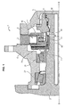
- the figure 1 shows a partial sectional view of a hydraulic apparatus according to one aspect of the invention. This figure shows the axis of rotation XX of the hydraulic apparatus 1.
- the hydraulic apparatus 1 comprises a shaft 2, a cam 3, typically a multilobe cam, a cylinder block 4, a distributor 51, a distributor cover 52 and a housing 6.
- the casing 6 and the shaft 2 are rotatably mounted relative to each other, typically by means of bearings, in this case two conical bearings 21.
- the cam 3 is typically formed of a ring adjacent to the axially inner face of the casing 6, and comprises on its radially inner surface, a series of lobes equi-distributed around the X-X axis. Each of the lobes typically has a generally sinusoidal appearance.
- the cam 3 is linked and integral in rotation with the casing 6.
- the cylinder block 4 is placed inside the ring forming the cam 3. It defines a plurality of cylinders 41 oriented radially with respect to the axis XX and opening onto the outer peripheral face of the cylinder block 4 opposite the cam 3.
- a piston 42 is mounted to slide radially respectively in each of the cylinders 41. Each piston 42 bears on the radially inner surface of the cam 3.
- the cylinder block 4 has a central bore through which it is engaged on the end of the shaft 2 of the hydraulic apparatus 1.
- the distributor 51 and the distributor cover 52 are adapted to apply in a controlled manner a fluid under pressure successively to each of the pistons 42, more precisely in the internal chamber of the cylinders 41 adjacent to the pistons, so that the successive support of the pistons 42 on the lobes of the cam 3 causes the relative rotation of the cylinder block 4 and the elements which are connected to it with respect to the cam 3 and thus to the housing 6 or vice versa.
- a fluid under pressure successively to each of the pistons 42, more precisely in the internal chamber of the cylinders 41 adjacent to the pistons
- a distribution plane 53 is defined between the distributor 51 and the cylinder block 4, corresponding to the faces of the distributor 51 and the cylinder block 4 adapted to be brought into contact with one another.
- the distributor cover 52 is rotatably connected to the shaft 2, while the distributor 51 is rotatably connected to the housing 6 by means not shown in detail.
- the cylinder block 4 further comprises a spring 43 disposed in each of the cylinders 41, so as to rest on the radially inner face of each of the pistons 42, and thus keep them resting against the cam 3 even in the absence of hydraulic pressure.
- the hydraulic apparatus 1 further comprises engagement means 7 adapted to, during the application of a command, immobilize the cylinder block 4 with respect to the shaft 2.
- the engagement means 7 are fixedly mounted around one end of the shaft 2, so as to be partially arranged between the cylinder block 4 and the shaft 2.
- the engagement means 7 further have a bearing surface 71 adapted to engage the cylinder block 4.
- the bearing surface is a radial collar, arranged to frictionally engage a side surface of cylinder block 4.
- the engagement means 7 can be controlled so as to engage the cylinder block 4, and via the application of a sufficient contacting force, immobilize the cylinder block 4 with respect to the engagement means 7 , and thus with respect to the shaft 2.
- This immobilization of the cylinder block 4 with respect to the shaft 2 thus makes a displacement of the hydraulic apparatus 1, that is to say its commissioning as defined previously.
- the springs 43 keep the pistons 42 in contact with the cam 3 and therefore force them to follow the cam 3 in the case of a hydraulic driving apparatus, which then has a pump operation.
- the movement of the pistons 42 thus implies a self-suction; and a hydraulic flow will be established in the pipes of the associated hydraulic circuit.
- the springs 43 then have an active role when the engagement means are not actuated, in that they keep the pistons 42 in contact with the cam 3.
- the cylinder block 4 is therefore synchronized with respect to the cam 3, ie connected in rotation with the cam 3
- an electromagnet is provided on the engagement means 7 or on the cylinder block 4, which thus makes it possible to obtain a controllable immobilization and control element.
- An example of such an embodiment which will be described hereinafter with reference to FIG. figure 6 is the use of brake disks respectively connected to the engagement means 7 and the cylinder block 4, the bringing into contact will allow the progressive immobilization of the cylinder block 4 with respect to the engagement means 7 and therefore with respect to the tree 2.
- a clutch device is used, that is to say a device with teeth and grooves disposed on the engagement means 7 and on the cylinder block 4, to immobilize them in rotation when these teeth and grooves are engaged.
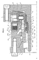
- the figure 2 shows a partial sectional view of an alternative hydraulic apparatus according to one aspect of the invention.
- the shaft 2 is rotatably connected to the cam 3.
- the distributor 51 is mounted fixed in rotation on the shaft 2, around the shaft 2, typically by means of grooves formed on the surface of the shaft 2 cooperating with ribs made in a bore of the distributor 51.
- the distributor cover 52 is rotatably mounted around the outer periphery of the distributor 51, and is rotatably connected to the housing 6.
- the shaft 2 comprises several sliding elements 24 arranged so as to allow the rotation of the cylinder block 4 with respect to the shaft 2.
- These sliding elements are for example skates, or ball bearings, rollers or needles.
- An elastic return element such as a spring 22 ensures the support of the distributor 51 against the cylinder block 4, with sufficient effort to achieve a seal between these two elements 51 and 4.
- the cylinder block 4 is rotatably mounted relative to these two sets.
- the engagement means 7 are here mounted on the distributor cover 52; it is a clutch device as described above, that is to say a device with teeth and grooves arranged on the engagement means 7 cooperating with teeth and grooves arranged on the cylinder block 4 and on the distributor cover 52.
- the engagement means 7 can be displaced in translation along the axis XX so as to be disposed only on one or the other of the cylinder block 4 or the distributor cover 52 and thus to leave these elements 4 and 52 free in rotation relative to each other, or so as to be straddling these two elements 4 and 52 and thus bind them in rotation.
- the engagement means 7 thus make it possible to link the cylinder block 4 in rotation with one of the sets defined above, in the occurrence the first set, that is to say the set not including the cam 3.
- the dispenser 51 as shown includes grooves 511 and 512 for conveying the fluid, which cooperate with grooves 521 and 522 provided in the dispenser cover 52 to form channels.
- Grooves 523 flanking the channels thus formed are arranged in the distributor cover 52, these grooves forming housings adapted to receive dynamic sealing elements.
- the grooves 511 and 512 made in the distributor 51 are advantageously made so as to have each two side walls 511a, 511b, 512a and 512b, these side walls being made so that for each of the grooves 511 and 512, the side wall which is the nearest cylinder block 4 has a surface greater than that which is furthest away.
- the side walls 511a and 512a have a surface greater than the surfaces 511b and 512b.
- This particular configuration of the grooves 511 and 512 thus makes it possible to ensure self-maintenance of the seal between the cylinder block 4 and the distributor 51.
- a spline 513 immobilizes in rotation the distributor 51 with respect to the shaft 2; the distributor 51 is thus integral in rotation with the cam 3 to the extent that the latter is integral in rotation with the shaft 2, to allow synchronizing the supply of the pistons on the cam profile.
- the figure 3 presents a variant of the embodiment of the figure 2 , wherein the engagement means 7 combine a dog structure with friction surfaces adapted to achieve a synchronization of the cylinder block 4 relative to the distributor cover 52 on which the engagement means 7 are mounted prior to the engagement of these two parts via the clutch.
- the engagement means 7 thus consist of two moving parts 72 and 73.
- the first movable part 72 is slidably mounted on the distributor cover 52, typically by means of complementary grooves and ribs, and has a friction surface 74 adapted to come into contact with a friction surface 48 of the cylinder block 4, the setting in contact with these surfaces 48 and 74 thereby causing friction to achieve synchronization of the cylinder block 4 with the distributor cover 52.
- the second movable part 73 is slidably mounted on the first movable part 72, for example also by means of complementary grooves and ribs, and is adapted to engage with complementary ribs and grooves arranged on the cylinder block 4 once the latter is synchronized with the dispenser cover 52.
- a ball stop 75 makes it possible to release the second mobile part 73 in translation only after the synchronization between the distributor cover 52 and the cylinder block 4 is achieved because of the engagement of the friction surfaces 74 and 48. Indeed, a dog-type engagement as realized by this second movable portion 73 is advantageously performed in static, that is to say when the two elements concerned are immobilized relative to each other.
- the engagement means 7 thus make it possible, during the application of a command, to link the cylinder block 4 and the distributor cover 52 in rotation with the first assembly, that is to say the assembly comprising not the cam 3.
- the engagement means 7 may further comprise a peripheral groove 741 allowing its movement via a lever or any other system involved.
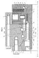
- the figure 4 shows another variant of a hydraulic apparatus 1 according to the invention, wherein the engagement means 7 are a pressure supply source adapted to apply pressure on a suitable surface of the distributor cover 52, and apply a pressure on the cylinder block 4 and thus link in rotation the cylinder block 4 with the part 6.
- the engagement means 7 are a pressure supply source adapted to apply pressure on a suitable surface of the distributor cover 52, and apply a pressure on the cylinder block 4 and thus link in rotation the cylinder block 4 with the part 6.
- the source of pressure supply is here represented schematically as a hydraulic pump 711, which may for example be a booster pump, adapted to supply pressure to a volume 712 located between the casing 6 and the distributor cover 52, and thus to apply a pressure on the latter so as to move it to the cylinder block 4, which abuts against a friction pad 64 connected to the casing 6, the pressure applied in the volume 712 being adapted to immobilize the cylinder block 4 relative to the housing 6 due to friction between the cylinder block 4 and the friction pad 64.
- a hydraulic pump 711 which may for example be a booster pump, adapted to supply pressure to a volume 712 located between the casing 6 and the distributor cover 52, and thus to apply a pressure on the latter so as to move it to the cylinder block 4, which abuts against a friction pad 64 connected to the casing 6, the pressure applied in the volume 712 being adapted to immobilize the cylinder block 4 relative to the housing 6 due to friction between the cylinder block 4 and the friction pad 64.
- the distributor cover 52 and / or the casing 6 advantageously comprise sealing means 713 sealing the volume 712 in which the pressure is applied.
- the engagement means 7 make it possible to link the cylinder block 4 in rotation with the first assembly during the application of a control, that is to say the assembly not comprising the cam 3.
- the friction pad is disposed at the interface between the cylinder block 4 and the distributor cover 52, while the cylinder block 4 bears against a sliding pad disposed on the 2.
- the application of the pressure within the volume 712 then leads to immobilization of the cylinder block 4 with respect to the distributor cover 52, and therefore with respect to the housing 6 due to friction between the cylinder block 4 and the friction pad of the distributor cover 52.
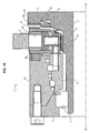
- the figure 5 presents another variant of a hydraulic apparatus 1 according to the invention as presented previously on the figure 2 .
- the distributor cover 52 is connected in rotation to the cylinder block 4 via an indexing element, for example a screw or a bolt, and mounted free to rotate relative to the casing 6.
- an indexing element for example a screw or a bolt
- the cylinder block 4 and the distributor cover 52 are rotatably mounted relative to these two assemblies.
- the engagement means 7 are here a clutch device as described above, that is to say a device with teeth and grooves arranged on the engagement means 7 cooperating with teeth and grooves provided on the housing 6 and on the dispenser cover 52.
- the engagement means 7 make it possible to connect the cylinder block 4 and the distributor cover 52 in rotation with the first assembly, that is to say the assembly not comprising the cam 3 during the application of a ordered.
- the figure 6 shows a partial sectional view of another variant of hydraulic apparatus according to one aspect of the invention.
- the shaft 2 is rotatably connected to the cam 3.
- the distributor 51 is mounted fixed in rotation on the shaft 2, around the shaft 2, typically by means of splines made on the surface of the shaft 2 cooperating with ribs made in a bore of the distributor 51.
- the dispenser cover 52 is rotatably mounted around the distributor 51, and is connected in rotation to the casing 6.
- the cylinder block 4 is arranged so that the pistons 42 are in the ring forming the cam 3, and are kept in contact with the cam 3 by means of the spring 43.
- the cylinder block 4 is here associated with a disk carrier 44 to which it is connected in rotation, the disk carrier 44 comprising a plurality of regularly spaced disks 45.
- the distributor cover 52 also further comprises a plurality of complementary discs 54 which are alternately arranged with the discs 45 of the disc carrier 44.
- These two groups of discs 45 and 54 have a similar operation to conventional brake discs; they are configured to alternate between a configuration in which they are not in contact and thus leave the distributor cover 52 and the cylinder block 4 free to rotate relative to each other, and a configuration in which they are in contact with each other. contact and thus immobilize the distributor cover 52 and the cylinder block 4 relative to each other under the effect of friction.
- a support element 8 is here arranged around the shaft 2, between the shaft 2 and the distributor 51.
- the engagement means are rotatably connected to the shaft 2 and the distributor 51, typically by means of ribs and grooves, and is movable in translation along the axis XX.
- the bearing element 8 comprises a thrust spring 82 positioned so as to make a thrust force of the distributor 51 against the cylinder block 4, thus providing a sealing support between the distributor 51 and the cylinder block 4.
- An elastic washer 83 is positioned bearing on the shaft 2 and acts on the support element 8 in opposition to the thrust force exerted by the thrust spring 82, thus making it possible to return to the disengaged position of the discs 45 and 54, that is the position of the system in which the cylinder block 4 is free to rotate relative to the distributor 51, and therefore relative to the housing 6.
- the washer 83 and the thrust spring 82 are configured to maintain the sealing between the distributor 51 and the cylinder block 4, whether the hydraulic apparatus is supplied with pressure or not.
- the pressure supply will tend to move the distributor 51 to the cylinder block 4 under the effect of the force resulting from the pressure applied to these walls 511a and 512a as described above.
- the distributor 51 being in abutment against the cylinder block 4, the latter will also be moved in the same direction, that is to say in the direction of a distance relative to the distributor cover 52.
- This relative displacement of the block 4 cylinders relative to the distributor cover 52 will thus cause the engagement of the discs 45 and 54, and thus link in rotation the cylinder block 4 relative to the assembly comprising the housing 6 and the distributor cover 52, thereby achieving the commissioning the hydraulic unit 1.
- the engagement means are here formed by the combination of the discs 45 and 54 and the support element 8, ensuring the engagement or not in rotation of cylinder block 4 relative to the housing 6 and the distributor cover 52 .
- the figure 7 presents another variant of hydraulic apparatus according to one aspect of the invention.
- This variant has an operation similar to that presented on the figure 6 , in which the discs 45 and 54 have been replaced by two conical half-shells 46 and 47 rotatably connected respectively to the cylinder block 4 and to the distributor cover 52.
- These two tapered half-shells 46 and 47 are configured so that when the cylinder block 4 and the distributor cover 52 are displaced in the direction of a distance relative to each other, the surfaces of these two conical half-shells 46 and 47 engage by friction, and thus connect in rotation the cylinder block 4 and the distributor cover 52.
- the pressure supply will tend to move the distributor 51 to the cylinder block 4 under the effect of the force resulting from the pressure applied to these walls 511a and 512a as described above.
- the distributor 51 being in abutment against the cylinder block 4, the latter will also be moved in the same direction, that is to say in the direction of a distance relative to the distributor cover 52.
- This relative displacement of the block cylinders 4 with respect to the distributor cover 52 will thus cause the engagement of the two tapered half-shells 46 and 47, and thus rotate the cylinder block 4 in relation to the assembly comprising the casing 6 and the distributor cover 52, thus realizing the commissioning of the hydraulic apparatus 1.
- the engagement means are here formed by the combination of the two tapered half-shells 46 and 47 and the support element 8, ensuring the engagement or not in rotation of cylinder block 4 with respect to the casing 6 and the distributor cover 52.
- the figure 8 presents a variant of the figure 6 wherein the support member 8, the thrust spring 82 and the washer 83 have been removed.
- a return means 9 is arranged so as to tend to move the cylinder block 4 to disengage it in rotation with respect to the distributor cover 52 and the casing 6, by disengaging the disks 45 from the cylinder block of the complementary disks 54 of the distributor cover. 52, that is to say disengaging the existing clutch between the cylinder block 4 and the housing 6 formed by the disks 45 and 54.
- the return means 9 is a washer type thrust spring, commonly referred to as the Belleville washer.
- the return means 9 maintains the cylinder block 4 in contact with the distributor 51, and therefore provides a seal between these two parts thus enabling the hydraulic apparatus 1 to be put into operation by feeding the pistons 42. of the cylinder block 4.
- the dispenser 51 as shown includes grooves 511 and 512 for fluid flow, which cooperate with grooves 521 and 522 provided in the dispenser cover 52 to form channels.
- Grooves 523 flanking the channels thus formed are arranged in the distributor cover 52, these grooves forming housings adapted to receive dynamic sealing elements.
- the grooves 511 and 512 made in the distributor 51 are advantageously made so as to have each two side walls 511a, 511b, 512a and 512b, these side walls being made so that for each of the grooves 511 and 512, the side wall which is the nearest cylinder block 4 has a surface greater than that which is furthest away.
- the side walls 511a and 512a have a surface greater than the surfaces 511b and 512b.
- the diameter of the distributor 51 increases as it approaches its contact surface with the cylinder block 4.
- the distributor 51 can thus be called stepped distributor.
- This particular configuration of the grooves 511 and 512 thus makes it possible to ensure a self-maintenance of the seal between the cylinder block 4 and the distributor 51.
- the distributor 51 is connected in rotation to the shaft 2; the distributor 51 is thus integral in rotation with the cam 3 to the extent that the latter is integral in rotation with the shaft 2, to allow synchronizing the supply of the pistons on the cam profile.
- a similar function can be achieved by arranging in the distributor 51, a thrust chamber, arranged so that its pressure supply causes a displacement of the distributor 51 to the cylinder block 4.
- the figure 9 presents another embodiment in which the cylinder block 4 is adapted to be rotatably connected to the shaft 2 during the application of a command; the cylinder block 4 comprises a plurality of discs 45 adapted to cooperate with a plurality of other discs 25 connected to the shaft 2.
- the operation is similar to that of the embodiment shown on the figure 8 .
- the return means 9 shown here as a Belleville washer, holds the cylinder block 4 in abutment against the distributor 51, and disengages the disks 45 and 25 forming the clutch between the cylinder block 4 and the shaft 2.
- the staged structure of the distributor 51 causes a displacement of the distributor 51 towards the cylinder block 4, and an engagement of the discs 45 and 25, thus linking the cylinder block 4 to the shaft 2 and rotating placing the hydraulic apparatus into cubic capacity 1.
- Such a fixed cam structure 3 is advantageous in terms of wear; when the hydraulic apparatus 1 is not in operation, the cam 3, the cylinder block 4, the distributor 51 and the dispenser cover 52 are immobile, which in particular avoids the wear of the sealing elements between these parts.
- return means 9 may be used. It may be mentioned in particular the use of a friction pad with one or more compression springs, a pulling element associated with a compression spring mounted in abutment on the distributor 5.
- the return means 9 can also be mounted in abutment on another element of the hydraulic apparatus 1, when it carries out a maintenance of the cylinder block 4 against the distributor 51.
- the figure 10 presents another embodiment in which the cylinder block 4 is adapted to be rotatably connected to the shaft 2 during the application of a command.
- connection in rotation between the cylinder block 4 and the shaft 2 is formed by a synchronizing element in rotation and by teeth.
- the synchronizing element as presented is a synchronization piston 91, rotatably connected to the shaft 2 for example by means of splines.
- the synchronization piston 91 is slidably mounted along the X-X axis, and is coupled to a washer 92 arranged in abutment on the shaft 2 producing a spring function between the shaft 2 and the synchronization piston 91.
- the cylinder block 4 and the shaft 2 each have splines, respectively 94 and 95, arranged to engage when the cylinder block is displaced along the axis XX so as to abut on the shaft 2.
- the displacement of the cylinder block 4 along the axis XX is typically carried out under the effect of the fluid supply of the distributor 51 which causes a thrust force of the distributor 51 on the cylinder block 4.
- the illustrated embodiment also comprises an actuating piston 96 adapted to achieve a thrust force on the cylinder block 4 and thus move it together with the effect of the fluid supply of the distributor 51.
- the cylinder block 4 comprises one or more housings in the form of angular sectors arranged facing the synchronization piston 91.
- the contact between the piston 91 and the cylinder block is by friction, so that the contact between the cylinder block 4 and the synchronization piston 91 causes a rotation engagement of the cylinder block 4 with respect to the synchronization piston 91 and thus with respect to the shaft 2.
- the shape of angular sectors of the housing allows a rotational engagement of the cylinder block 4 relative to the synchronization piston 91 while allowing an angular movement between these two elements.
- the cylinder block 4 continues its displacement along the axis XX until the grooves 94 and 95 of the cylinder block 4 and the shaft 2 respectively engage, thus forming a commitment by dog between the cylinder block 4 and the shaft 2.
- the washer 92 allows the translation of the synchronization piston 91 with the cylinder block 4 along the axis XX.
- the setting cylinder is thus adapted to the direction of operation of the hydraulic device 1 due to the floating engagement of the cylinder block 4 which allows positioning of the internal conduits adapted to the direction of rotation of the hydraulic device 1.
- the figures 11 and 12 illustrate a structure having an operation as described with reference to the figure 9 , integrated into an assembly comprising a differential linked to two half-shafts driving wheels.
- the casing 6 is fixed, and the hydraulic apparatus 1 is associated with a differential 23 disposed in the casing 6.
- the cam 3, the distributor 51 and the distributor cover 52 are here rotatably connected to the casing 6, the shaft 2 being rotating.
- the body (commonly called cage) of the differential 23 is rotatably connected to the shaft 2.
- This variant finds an application for example to provide assistance on an axle of a vehicle, the two half-shafts 2a and 2b are each linked to a wheel, respectively 2c and 2d. It is then enough to engage a pump to supply the hydraulic apparatus 1 so that the latter engages and operates as a motor to provide hydraulic assistance on the shaft 2, in this case a vehicle axle.
- the rotational engagement of the cylinder block 4 is progressive; the higher the pressure delivered by the distributor 51, the higher the friction force between the discs 45 of the clutch of the cylinder block 4 and the complementary discs 54 or 25.
- the cylinder block 4 is rotatably mounted relative to said first and second sets.
- the cam 3 is rotatably connected to one or other of these sets; for example at the first set in the embodiment shown on the figure 1 , and to the second set in the embodiment shown on the figure 2 .
- the engagement means 7 make it possible to immobilize the cylinder block 4 with respect to the other of said first or second assemblies during the application of a command, for example the supply of pressure to the hydraulic apparatus 1 or the engagement of an actuator, so that the cylinder block 4 and the cam 3 are each connected in rotation to a separate assembly, which achieves the setting in cubic capacity of the hydraulic apparatus.
- a command for example the supply of pressure to the hydraulic apparatus 1 or the engagement of an actuator
- the engagement means 7 can act directly on the cylinder block 4, for example in the embodiment shown in FIG. figure 1 where the engaging means come directly into contact with the cylinder block 4 in order to immobilize it in rotation, or indirectly via an action performed on another element, such as, for example, the distributor cover 52 in the embodiment represented on the figure 2 or the distributor 51 in the embodiment shown on the figure 1 .
- the immobilization of the cylinder block 4 with respect to one or the other of the assemblies is advantageously carried out progressively, for example by progressive application of the contacting force in order to achieve a progressive commissioning without stroke.
- the engagement means 7 may in particular be actuated by a booster pump of a hydraulic circuit associated with the hydraulic apparatus.
- the springs 43 applying the pistons 42 to the cam 3 imply that the hydraulic apparatus 1 is self-aspirating as already detailed above with reference to the figure 1 that is, this hydraulic apparatus 1 can be used as a pump without having to be coupled to a booster pump to avoid the risk of cavitation.
- the invention thus makes it possible to commission the hydraulic apparatus 1 at a non-zero speed and at a zero flow rate. This changes from a disengaged configuration in which the flow is zero, to a configuration in which the relative rotation of the two sets causes a flow of fluid.
- the commissioning can be carried out progressively until immobilization of the cylinder block 4 with respect to one or the other of the assemblies for example under the effect of friction, this immobilization then being able, in certain variants, to be doubled by means of a clutch or other suitable locking means.
- the booster pump is thus optional and if necessary minimized, its function being limited to the compensation of any leaks.
- the invention finds particular application on the hydraulic assistance circuits of vehicles, for example trucks, agricultural vehicles or construction equipment, or on commercial vehicles or even automobiles.
- a hydraulic apparatus 1 with rotating casing 6 and fixed shaft 2 as described above the hydraulic apparatus 1 is then arranged in such a way that its fixed part forms a wheel spindle, the rotating casing being linked to the wheel.
- the commissioning of the hydraulic apparatus 1 thus typically makes it possible to switch from a transmission of traction or propulsion type to a transmission of 4x4 type.
- a transmission of traction or propulsion type For example, in the case of a 4-wheel vehicle having a main motor driving its front wheels, it is advantageous to equip the rear wheels of such hydraulic devices 1 and thus switch to 4x4 transmission when commissioning these hydraulic devices .
- the figure 13 presents another variant of use of a hydraulic apparatus according to one aspect of the invention.
- the discs 45 and 25 are here arranged in a controlled pressure sealed chamber 56 by means of a control chamber 57.
- the control chamber 57 is connected to the conduits of the distributor 51.
- the sealed chamber 56 is filled with oil.
- the control chamber 57 is configured so as to control the pressure within the sealed chamber 56, thereby changing the viscosity of the oil in the sealed chamber 56.
- the increase in the viscosity of the oil in the sealed chamber 56 makes a commitment of the discs 45 and 25 by visco-coupling.
- the oil within the sealed chamber 56 has a low viscosity and therefore does not perform the engagement of the discs 45 and 25.
- a freewheel control for example a spring washer, is arranged so as to release the pressure within the sealed chamber 56 and thus to pass the hydraulic apparatus 1 in freewheel configuration.
- a chain assembly of several hydraulic devices 1 according to the invention is carried out on a vehicle.
- a first hydraulic apparatus is thus mounted on a wheel axle, and a second hydraulic apparatus on a driving axle linked to an engine such as a combustion engine of the vehicle.
- an engine such as a combustion engine of the vehicle.
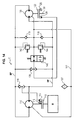
- the figure 14 presents an embodiment of such an assembly.
- This assembly comprises a hydraulic circuit C comprising two hydraulic devices 110 and 120 respectively operating in pump and motor.
- These two hydraulic devices 110 and 120 are each coupled to a clutch, respectively 112 and 122.
- the clutch 112 couples the pump 110 with a motor block M, typically a heat engine that can be associated with a gearbox.
- the clutch 122 couples the hydraulic motor 120 with a shaft 130, for example a vehicle axle.
- the clutches 112 and 122 are controlled by respective hydraulic controls 114 and 124, adapted to engage the associated clutch when a control pressure is applied, and disengage it when the applied pressure is less than one. given threshold value.
- hydraulic controls 114 and 124 are each doubled with a primary control, respectively 115 and 125, the clutches 112 and 122 can each be engaged either by a single primary or hydraulic control, or by a combined effect of the two controls.
- the primary controls 115 and 125 are electrical controls, it being understood that other variants are possible, in particular by means of pneumatic, mechanical or hydraulic controls.
- the hydraulic circuit C has a line connecting the inlet of the hydraulic pump 110 to the discharge of the hydraulic motor 120, and a line connecting the discharge of the hydraulic pump 110 to the inlet of the hydraulic motor 120.
- these lines respectively BP and HP corresponding to the low pressure line and the high pressure line of the circuit C.
- the circuit C as shown comprises two shuttle valves 116 and 126, each connecting the line HP to the line BP, and delivering a pressure respectively to the hydraulic controls 114 and 124.
- shuttle valves 116 and 126 are configured to take the highest pressure of the two lines HP and BP, in this case the high pressure line connected to the discharge of the hydraulic pump 110 and route it to their hydraulic controls 114 and 124 respectively.
- the hydraulic circuit C further comprises pressure relief valves 142 and 144 adapted to allow the evacuation of the fluid in the circuit C, these pressure relief valves being connected respectively to the line BP and the line HP, and being configured to pass when the pressure in the line to which they are connected exceeds a threshold value.
- hydraulic devices 110 and 120 have their respective housings interconnected by a same drain line 117, itself connected to the lines HP and BP respectively by check valves 118 and 119.
- This common drain line 117 makes it possible to balance the pressure in the housings of the hydraulic units 110 and 120 with the high-pressure line HP in order to disengage the hydraulic apparatus. It also makes it possible to achieve leakage suction of the hydraulic devices 110 and 120 to the hydraulic circuit C; the non-return valves 118 and 119 performing a function of supplying the hydraulic circuit C, thus making it possible to produce a self-suction system that does not require feeding means.
- the drain line 117 furthermore typically comprises a breather 127, or system for evacuating oil vapors to the external environment.
- the drain line 117 is then advantageously also connected to the casing of this gearbox, which makes it possible to obtain a system having a drain line typically provided with a single breather for the gearbox and the hydraulic devices.
- the drain then makes a reserve for the oil supply of the two hydraulic devices.
- the primary control 115 of the clutch 112 is actuated so as to couple the hydraulic pump 110 to the motor M, and thus make a flow in the circuit C by the pump hydraulic 110, which then defines HP high pressure lines and BP low pressure depending on its direction of operation.
- the primary control 125 is then actuated so as to couple the hydraulic motor 120 with the shaft 130.
- a hydraulic motor 120 with a stepped distributor as described above, especially with reference to the figures 6 , 7 , 8 , and 9 , the supply of the hydraulic motor 120 will cause the rotational engagement of the cylinder block 4 relative to one or other of the sets as defined above, and thus put the hydraulic motor 120 in displacement.
- the system thus engaged thus drives the shaft 130 in rotation and then provides a hydraulic assistance, while ensuring its continued operation.
- Disengagement of the assistance can be achieved either by no longer operating the primary controls 115 and 125 or by applying inverse primary commands, going in the direction of the disengagement of one or clutches 112 and / or 122, and / or or via the distributor 146 to drain the lines HP and BP by sending the fluid into the housing of the motor 120 and / or the pump 110 can thus reduce the torque of the clutches 112 and 122 so as to lower them below the threshold value to train the associated hydraulic apparatus.
- the assembly associated with the hydraulic devices 1 is therefore simple to implement, and does not require multiple switching elements in order to establish several pressure levels for the commissioning of the hydraulic devices 1.
- the hydraulic pump 110 is mounted on a vehicle primary axle, linked to one or more driving wheels, while the hydraulic motor 120 is mounted on a vehicle sub-axle.
- the primary axle is driven by a primary engine, typically thermal.
- the hydraulic pump 110 therefore rotates at the same speed as the driving wheels of the primary axle of the vehicle, and the hydraulic motor 120 rotates at the same speed as the secondary axle of the vehicle.
- Such an assembly of the hydraulic devices on the axles thus makes it possible in particular to overcome the reduction ratios inherent in previous mountings of the hydraulic units on thermal engine power take-offs or on speed shafts, and to propose a simplified structure for the performing hydraulic assistance on a vehicle.
- the hydraulic pump 110 can then feed two hydraulic motors, each connected to a half axle axle driving a wheel.
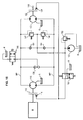
- the figure 15 presents a variant of the previous assembly.
- This assembly also comprises two hydraulic devices 1 as presented above, one 110 operating as a pump and the other 120 operating as a motor.
- This diagram shows the drain lines of the housings of these hydraulic devices 110 and 120, each connected to the ambient pressure tank R.
- this assembly makes it possible to carry out the commissioning of the two hydraulic units, in order to provide hydraulic assistance on the shaft 130 coupled to the motor 120 via the clutch 122.
- the overpressure valves 142 and 144 are arranged in such a way as to Discharge the excess pressure from the HP and LP lines in circuit C or in the crankcases of hydraulic devices 110 and 120.
- the distributor 146 here performs a drain function HP and BP lines, discharging the highest pressure of these two lines in the tank R, the highest pressure of the two lines HP and BP being taken by means of a Shuttle valve 136.
- This assembly comprises a booster pump 150 which draws fluid from the tank R, and performs the feeding of the circuit. It is associated with a pressure relief valve 152 allows to discharge the excess pressure in the reservoir R.
- This booster pump 150 is also associated with an engagement distributor 156, for connecting the hydraulic controls 114 and 124 respectively driving the clutches 112 and 122 to the booster pump 150, or to a tank at ambient pressure R.
- the activation of the engagement distributor 156 makes the engagement of the two clutches 112 and 122, and thus the commissioning of the two hydraulic devices 110 and 120.
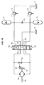
- the figure 16 presents another variant in which the hydraulic apparatus is powered by accumulators, which allows for an energy recovery circuit.
- this diagram shows a hydraulic apparatus 120 according to the invention, linked to a shaft 130, said hydraulic apparatus here having a motor operation.
- the commissioning of this engine 120 is controlled by means of the clutch 122, which is itself controlled by the hydraulic control 124.
- a shuttle valve 126 takes the highest pressure from the two hydraulic branches connected to the motor 120, and applies it to the control 124.
- the pressure supply is performed by means of two accumulators 171 and 172.
- the accumulator 171 is a high pressure accumulator
- the accumulator 172 is a low pressure accumulator .
- An anti-return valve 173 is arranged between these two accumulators, so as to prevent the pressure from being higher than the level of the low-pressure accumulator 172 with respect to the pressure at the level of the high-pressure accumulator 171.
- Two pressure relief valves 174 and 175 make it possible to discharge an excess of pressure in a tank R at ambient pressure.
- control means 166 comprising in particular electric, pneumatic or electrical hydraulic controls as well as return means such as springs ensuring the return to the equilibrium position of the distributor 160 in the absence of pilot control .
- This distributor 160 can alternate between three configurations that are described below.
- a first configuration which is the configuration represented on the figure 16
- the fourth and fifth ports 164 and 165 are connected to the second port 162, while the first and third ports 161 and 163 are closed.
- This configuration thus connects the intake and the discharge of the motor 120 to the tank R; there is no pressure to engage the clutch 120, and the motor 120 is disengaged.
- the first port 161 is connected to the fifth port 165
- the third port 163 is connected to the fourth port 164
- the second port 162 is closed.
- This configuration therefore connects the motor 120 to the accumulators 171 and 172, which thus defines a high pressure line and a low pressure line, in this case respectively the line connected to the high pressure accumulator 171 and the line connected to the accumulator low pressure 172, engages the clutch 122 and puts into operation the motor 120 so that it rotates the shaft 130.
- the third configuration is similar to the second configuration, but reverses the links of the first and third ports 161 and 163 with the fourth and fifth orifices 164 and 165, thus making it possible to reverse the direction of rotation of the motor 120.
- the motor 120 is supplied with pressure by the high pressure accumulator, and then discharges into the low pressure accumulator which performs a function of energy recovery.
- this circuit exploits the advantageous structure of the hydraulic apparatus according to the invention, in this case the motor 120, making it possible to carry out a simple commissioning, without wear or noise, which thus makes it possible to obtain a simplified circuit and thus reduced in terms of size, cost and mass.
- the vehicle is then advantageously also equipped with a computer that receives a characteristic information of the speed of driven motors linked to the wheels and a characteristic information of the speed of rotation of the pump.
- the calculator then performs a displacement adjustment of the hydraulic pump as soon as it is started so that the displacement of the pump multiplied by its rotational driving speed is equal to the displacement of the total of the N motors multiplied by the speed of rotation.
- drive driven motors related to Epsilon plus wheels.
- Epsilon value represents a slip that provides a pull effect. Epsilon may be zero or very weak at the time of clutch The engine's expected displacement can take into account a leak rate or circuit losses.
- the clutch of the hydraulic device or devices as described above and operating in motor can be done concomitantly, or after a slight delay.
- the engines When the engines are powered, but not engaged, they can rotate without torque at a speed approaching that of the shaft on which they are placed, which is an advantageous situation to promote a clutch without jolt, especially if the linkage system of the Crankcase block is of the claw type.
- the pump is running and the motors are running, there is very little torque supplied, and the pressure difference between the hydraulic supply and return lines is very small.
- the computer When the pressure is established in the closed loop of the hydraulic circuit, thus creating a low pressure return line and a high pressure supply line, the computer performs a control of the displacement of the pump as a function of the pressure variations in the hydraulic circuit. hydraulic circuit, for example by means of point pressure readings at different points of the circuit.
- the displacement control of the hydraulic pump can be varied, either in torque or speed, to achieve the traction or the retention of the axles conducted as well known to those skilled in the art.
- This control from the pressure information can be activated from the moment when a pressure difference greater than a predetermined threshold desired by those skilled in the art appears between the hydraulic supply and return lines. he can also be activated after a delay after the clutch or other means of detecting that the clutch of the engines is effective.
- This particular embodiment allows a drive by the engine driven more immediate, resulting in less effort, slippage, wear, noise, avoiding jolts or pressure peaks.
Description
La présente invention concerne le domaine des appareils hydrauliques et des moyens associés pour permettre la mise en débit de tels appareils hydrauliques.The present invention relates to the field of hydraulic devices and associated means for enabling the flow of such hydraulic devices.
Dans l'ensemble du présent texte, on désignera par appareil hydraulique un appareil pouvant fonctionner en tant que moteur ou que pompe hydraulique, et étant par exemple piloté au moyen de l'inclinaison d'un plateau de commande dudit appareil hydraulique. Un appareil hydraulique comprend de manière conventionnelle une pluralité de pistons disposés dans des logements, et effectuant des mouvements de va et vient au contact d'une came.Throughout the present text, the term "hydraulic apparatus" means a device that can operate as a motor or hydraulic pump, and for example being controlled by means of the inclination of a control plate of said hydraulic apparatus. A hydraulic apparatus conventionally comprises a plurality of pistons disposed in housings, and reciprocating in contact with a cam.
On connaît les appareils hydrauliques présentant une configuration de roue libre, c'est-à-dire une configuration dans laquelle l'appareil hydraulique fonctionne sans pression et sans débit de fluide et plus particulièrement où les pistons ne sont pas en contact avec la came, une telle configuration étant par exemple avantageuse sur des engins ayant des conditions de travail mixtes. A cette configuration de roue libre s'oppose la configuration de travail, dans laquelle les pistons sont au contact de la came, et l'appareil hydraulique fonctionne avec une pression et un débit de fluide.Hydraulic devices having a freewheel configuration are known, that is to say a configuration in which the hydraulic apparatus operates without pressure and without fluid flow and more particularly where the pistons are not in contact with the cam, such a configuration being for example advantageous on machines having mixed working conditions. In this freewheel configuration the work configuration is opposed, in which the pistons are in contact with the cam, and the hydraulic apparatus operates with a pressure and a fluid flow rate.
Une transmission hydraulique comprend ainsi typiquement un appareil hydraulique qui est en configuration de roue libre lorsque la transmission hydraulique n'est pas sollicitée, et passe en configuration de travail lorsqu'elle est sollicitée.A hydraulic transmission thus typically comprises a hydraulic apparatus which is in freewheel configuration when the hydraulic transmission is not requested, and goes into working configuration when it is requested.
Ce passage de la configuration de roue libre à la configuration de travail est réalisé par une sortie des pistons, qui sont amenés au contact de la came, ou plus précisément leurs extrémités libres sont placées au contact de la came. Ce passage de la configuration de roue libre à la configuration de travail est appelé la mise en service de l'appareil hydraulique, et correspond à l'application d'un débit à l'appareil hydraulique.This passage from the freewheel configuration to the working configuration is achieved by an output of the pistons, which are brought into contact with the cam, or more precisely their free ends are placed in contact with the cam. This transition from the freewheel configuration to the working configuration is called the commissioning of the hydraulic apparatus, and corresponds to the application of a flow to the hydraulic apparatus.
La mise en service peut être réalisée en statique ou en dynamique.Commissioning can be done statically or dynamically.
La mise en service en statique implique l'immobilisation des différents composants, et est donc très contraignante en termes d'utilisation.Static commissioning involves the immobilization of the various components, and is therefore very restrictive in terms of use.
En dynamique, la mise en service entraine un appel instantané de débit, que les sources d'alimentation en débit ne peuvent pas fournir. Ceci implique que les pistons peuvent ne pas être tous en contact instantanément contre la came, et entraine donc un bruit.In a dynamic environment, provisioning results in an instantaneous rate call, which the flow supply sources can not provide. This implies that the pistons may not all be in contact instantly against the cam, and therefore causes a noise.
De plus, la mise en service telle que communément réalisée dans de tels appareils hydrauliques entraine des chocs lors de la mise en contact des pistons sur la came, ce qui a un impact direct sur la durée de vie du moteur, ainsi que du bruit, ce qui est désagréable pour l'utilisateur, que la mise en service soit réalisée en statique ou en dynamique. En outre, la mise en service de l'appareil hydraulique n'est pas toujours instantanée, car il faut amener suffisamment d'huile pour sortir tous les pistons.In addition, the commissioning as commonly performed in such hydraulic devices causes shocks when the pistons come into contact with the cam, which has a direct impact on the service life of the engine, as well as the noise, which is unpleasant for the user, whether commissioning is performed in static or dynamic. In addition, the commissioning of the hydraulic device is not always instantaneous, because it is necessary to bring enough oil to take out all the pistons.
L'art antérieur est représenté par
La présente invention vise à proposer un système ne présentant pas de tels inconvénients.The present invention aims to propose a system that does not have such disadvantages.
A cet effet, l'invention propose un appareil hydraulique à pistons radiaux, comprenant :
- un carter définissant un premier ensemble,
- un arbre définissant un second ensemble, lesdits premier et second ensembles étant libres en rotation l'un par rapport à l'autre,
- une came multilobes liée en rotation à l'un desdits premier ou second ensembles,
- un distributeur et un couvercle de distributeur
- un bloc cylindres monté libre en rotation par rapport auxdits premier et second ensembles, et comprenant une pluralité de cylindres dans lesquels sont disposés des pistons guidés à coulissement radial dans des cylindres respectifs du bloc cylindres et prenant appui sur les lobes de la came, ledit appareil comprend des ressorts d'appui disposés dans lesdits cylindres de manière à maintenir les pistons en appui contre la came,
- a housing defining a first assembly,
- a shaft defining a second set, said first and second sets being free to rotate relative to one another,
- a multilobe cam rotatably connected to one of said first or second sets,
- a dispenser and a dispenser cover
- a cylinder block mounted free to rotate with respect to said first and second assemblies, and comprising a plurality of cylinders in which pistons are guided radially sliding in respective cylinders of the cylinder block and resting on the lobes of the cam, said apparatus comprises bearing springs disposed in said cylinders so as to keep the pistons resting against the cam,
Ledit appareil hydraulique présente typiquement une ou plusieurs des caractéristiques suivantes, prises indépendamment ou en combinaison :
- lesdits moyens d'engagement sont adaptés pour réaliser un engagement par frottement dudit bloc cylindres avec ledit premier ou second ensemble ;
- l'un desdits ressorts d'appui présente une raideur supérieure à la raideur desdits autres ressorts d'appui, de manière à définir une indexation du bloc cylindres par rapport à la came lorsque le bloc cylindres est libre en rotation par rapport auxdits premier et second ensembles.
- said engaging means are adapted to frictionally engage said cylinder block with said first or second set;
- one of said bearing springs has a greater stiffness than the stiffness of said other bearing springs, so as to define an indexing of the cylinder block with respect to the cam when the cylinder block is free to rotate relative to said first and second sets.
La came est typiquement :
- soit liée en rotation à l'arbre, les moyens d'engagement étant adaptés pour lier en rotation le bloc cylindres au carter ;
- soit liée en rotation au carter, les moyens d'engagement étant adaptés pour lier en rotation le bloc cylindres à l'arbre.
- is linked in rotation to the shaft, the engagement means being adapted to rotate the cylinder block to the housing;
- is connected in rotation to the housing, the engagement means being adapted to rotate the cylinder block to the shaft.
L'appareil hydraulique comprenant en outre avantageusement un piston de synchronisation lié en rotation à l'autre desdits premier ou second ensembles et adapté pour coopérer avec un logement aménagé dans le bloc cylindres, ledit logement formant un secteur angulaire de manière à définir deux positions de butée du piston de synchronisation dans ledit logement, lesdites deux positions de butée définissant deux configurations des conduits internes du distributeur et du bloc cylindres correspondant aux deux sens de rotation de l'ensemble mobile dudit appareil hydraulique, ledit piston de synchronisation étant configuré de manière à positionner le bloc cylindres dans la position de butée adaptée préalablement à l'immobilisation par les moyens d'engagement du bloc cylindres par rapport à l'autre desdits premier ou second ensembles.The hydraulic apparatus further advantageously comprises a synchronization piston rotatably connected to the other of said first or second sets and adapted to cooperate with a housing provided in the cylinder block, said housing forming an angular sector so as to define two positions of stop of the synchronization piston in said housing, said two stop positions defining two configurations of the inner ducts of the distributor and the cylinder block corresponding to the two directions of rotation of the moving assembly of said hydraulic apparatus, said synchronization piston being configured so as to positioning the cylinder block in the stop position adapted prior to immobilization by the engagement means of the cylinder block relative to the other of said first or second sets.
Selon un mode de réalisation particulier, lesdits moyens d'engagement comprennent
- des moyens de rappel tendant à déplacer le bloc cylindres pour le désengager en rotation par rapport à l'autre desdits premier ou second ensembles, et
- des conduits internes du distributeur configurés pour, lors de l'application d'une pression, engager le bloc cylindres en rotation par rapport à l'autre desdits premier ou second ensembles.
- biasing means for moving the cylinder block to disengage it in rotation relative to the other of said first or second sets, and
- internal conduits of the distributor configured to, when applying a pressure, engage the cylinder block in rotation relative to the other of said first or second sets.
Selon un autre mode de réalisation particulier lesdits moyens d'engagement comprennent un électro-aimant, configuré de manière à, lors de son activation, générer un champ magnétique qui entraine une force d'attraction entre le bloc cylindres et un élément de frottement, de manière à immobiliser le bloc cylindres par rapport audit premier ou second ensemble.According to another particular embodiment, said engagement means comprise an electromagnet, configured so as, during its activation, to generate a magnetic field which causes a force of attraction between the cylinder block and a friction element, in order to immobilize the cylinder block with respect to said first or second set.
Selon encore un mode de réalisation particulier lesdits moyens d'engagement comprennent un dispositif à dents et rainures aménagées sur les moyens d'engagement adapté pour coopérer avec des dents et rainures aménagées sur le bloc cylindres ou sur ledit premier ou second ensemble de manière à immobiliser le bloc cylindres par rapport audit premier ou second ensemble.According to another particular embodiment, said engagement means comprise a device with teeth and grooves arranged on the engagement means adapted to cooperate with teeth and grooves arranged on the cylinder block or on said first or second assembly so as to immobilize the cylinder block with respect to said first or second set.
Selon un mode de réalisation particulier, lesdits moyens d'engagement comprennent
- une chambre étanche remplie d'huile et dans laquelle se trouvent des disques liés en rotation au bloc cylindres et à l'autre desdits premier ou second ensembles, et
- une chambre de commande adaptée pour piloter la pression au sein de la chambre étanche, de manière à réaliser un engagement par visco-couplage.
- a sealed chamber filled with oil and in which there are discs connected in rotation to the cylinder block and to the other of said first or second sets, and
- a control chamber adapted to control the pressure within the sealed chamber, so as to achieve a commitment by visco-coupling.
L'invention concerne également un système comprenant au moins deux appareils hydrauliques tels que définis précédemment, dans lequel un premier desdits appareils hydrauliques est lié à un moteur principal via un embrayage de manière à fonctionner en pompe, et alimenter via un circuit hydraulique, un second desdits appareils hydrauliques fonctionnant en tant que moteur pour réaliser une assistance sur un arbre d'entrainement d'une roue de véhicule, lesdits premier et second appareils hydrauliques comprenant une ligne de drain commune pour leurs carters respectifs reliée audit circuit hydraulique via des clapets anti-retour.The invention also relates to a system comprising at least two hydraulic devices as defined above, in which a first of said hydraulic devices is connected to a main motor via a clutch so as to operate as a pump, and to feed via a hydraulic circuit, a second said hydraulic apparatus functioning as a motor for providing assistance on a drive shaft of a vehicle wheel, said first and second hydraulic apparatus comprising a common drain line for their respective housings connected to said hydraulic circuit via anti-backflow valves; return.
L'invention concerne par ailleurs un système comprenant au moins un appareil hydraulique tel que défini précédemment fonctionnant en moteur et montés chacun sur un essieu mené d'un véhicule, et une pompe hydraulique à cylindrée variable, ledit système comprenant en outre un calculateur adapté pour piloter la cylindrée de la pompe hydraulique de sorte que la cylindrée de la pompe hydraulique multipliée par sa vitesse d'entrainement en rotation soit égale à la cylindrée des totale desdits moteurs hydrauliques multipliée par la vitesse d'entrainement des moteurs hydrauliques menés liés aux essieux plus Epsilon, où Epsilon représente un glissement qui procure un effet de traction.The invention furthermore relates to a system comprising at least one hydraulic apparatus as defined previously operating as a motor and each mounted on a driven axle of a vehicle, and a variable displacement hydraulic pump, said system further comprising a computer adapted for control the displacement of the hydraulic pump so that the displacement of the hydraulic pump multiplied its rotational driving speed is equal to the displacement of the total of said hydraulic motors multiplied by the driving speed of the hydraulic motors driven linked to the axles plus Epsilon, where Epsilon represents a sliding which provides a traction effect.
L'invention concerne par ailleurs, un véhicule comprenant un moteur primaire entrainant en rotation un essieu primaire définissant ainsi les roues motrices du véhicule, et un essieu secondaire, ledit véhicule comprenant un appareil hydraulique primaire tel que défini
précédemment monté sur ledit essieu primaire de manière à être entraîné en rotation à la même vitesse que lesdites roues motrices, et un appareil hydraulique secondaire tel que défini précédemment monté sur l'essieu secondaire de manière à être entraîné en rotation à la même vitesse que la ou les roues montées sur ledit essieu secondaire, lesdits appareils hydrauliques primaire et secondaire étant associés de manière à permettre l'entrainement de l'essieu secondaire par l'appareil hydraulique secondaire lors de la mise en service desdits appareils hydrauliques.The invention furthermore relates to a vehicle comprising a primary motor driving in rotation a primary axle thus defining the driving wheels of the vehicle, and a secondary axle, said vehicle comprising a primary hydraulic apparatus as defined
previously mounted on said primary axle so as to be rotated at the same speed as said driving wheels, and a secondary hydraulic apparatus as previously defined mounted on the secondary axle so as to be rotated at the same speed as the or the wheels mounted on said secondary axle, said primary and secondary hydraulic devices being associated so as to allow the driving of the secondary axle by the secondary hydraulic device during the commissioning of said hydraulic devices.
L'invention concerne en outre un procédé de mise en cylindrée d'un appareil hydraulique comprenant un carter définissant un premier ensemble, un arbre définissant un second ensemble, lesdits premier et second ensembles étant libres en rotation l'un par rapport à l'autre, une came multilobes liée en rotation à l'un desdits premier ou second ensembles, un bloc cylindres monté libre en rotation par rapport auxdits premier et second ensembles, et comprenant une pluralité de cylindres dans lesquels sont disposés des pistons guidés à coulissement radial dans des cylindres respectifs du bloc cylindres, prenant appui sur les lobes de la came et étant maintenus en appui contre la came,
ledit procédé étant caractérisé en ce qu'on pilote l'immobilisation du bloc cylindres par rapport à l'autre desdits premier ou second ensembles de manière à réaliser la mise en cylindrée de l'appareil hydraulique.The invention further relates to a method of placing a hydraulic apparatus into a cylinder comprising a casing defining a first set, a shaft defining a second set, said first and second sets being free to rotate relative to one another. a multilobe cam rotatably connected to one of said first and second assemblies, a cylinder block rotatably mounted relative to said first and second assemblies, and comprising a plurality of cylinders in which radially-sliding guided pistons are disposed in respective cylinders of the cylinder block, resting on the lobes of the cam and being held in abutment against the cam,
said method being characterized in that it controls the immobilization of the cylinder block relative to the other of said first or second sets so as to achieve the displacement of the hydraulic apparatus.
L'immobilisation du bloc cylindres par rapport à l'autre desdits premier ou second ensembles est avantageusement réalisée par application d'une pression dans un distributeur dudit appareil hydraulique entrainant le déplacement dudit distributeur de manière à ce qu'il agisse sur le bloc cylindres pour l'immobiliser par rapport à l'autre desdits premier ou second ensembles.The immobilization of the cylinder block relative to the other of said first or second assemblies is advantageously carried out by applying a pressure in a distributor of said hydraulic apparatus causing the displacement of said distributor so that it acts on the cylinder block for immobilize it with respect to the other of said first or second sets.
D'autres caractéristiques, buts et avantages de l'invention ressortiront de la description qui suit, qui est purement illustrative et non limitative, et qui doit être lue en regard des dessins annexés, sur lesquels :
- la
figure 1 présente une vue partielle en coupe d'un appareil hydraulique selon un aspect de l'invention, - la
figure 2 présente une vue partielle en coupe d'une variante d'appareil hydraulique selon un aspect de l'invention, - les
figures 3 à 10 présentent des vues en coupe partielle d'autres variantes d'appareils hydrauliques selon un aspect de l'invention, - les
figures 11 et12 présentent deux vues d'un exemple d'intégration d'une variante d'appareil hydraulique selon un aspect de l'invention sur un essieu de véhicule, - la
figure 13 présentent une vue d'une autre variante d'appareil hydraulique selon un aspect de l'invention couplé avec un différentiel pour une intégration par exemple sur un essieu de véhicule, - les
figures 14 à 16 présentent plusieurs exemples de montages mettant en oeuvre des appareils hydrauliques selon un aspect de l'invention.
- the
figure 1 has a partial sectional view of a hydraulic apparatus according to one aspect of the invention, - the
figure 2 has a partial sectional view of an alternative hydraulic apparatus according to one aspect of the invention, - the
Figures 3 to 10 show partial sectional views of other variants of hydraulic apparatus according to one aspect of the invention, - the
figures 11 and12 show two views of an example of integration of a variant of hydraulic apparatus according to one aspect of the invention on a vehicle axle, - the
figure 13 show a view of another variant of hydraulic apparatus according to one aspect of the invention coupled with a differential for integration for example on a vehicle axle, - the
Figures 14 to 16 present several examples of assemblies using hydraulic devices according to one aspect of the invention.
Sur l'ensemble des figures, les éléments communs sont repérés par des références numériques identiques.In all the figures, the common elements are identified by identical reference numerals.
La
L'appareil hydraulique 1 comprend un arbre 2, une came 3 typiquement une came multilobes, un bloc cylindres 4, un distributeur 51, un couvercle de distributeur 52 et un carter 6.The
Le carter 6 et l'arbre 2 sont montés tournant par rapport à l'autre, typiquement au moyen de roulements, en l'occurrence deux roulements coniques 21.The
Dans la description qui suit, on considérera que l'arbre 2 est fixe et que le carter 6 est tournant afin d'illustrer un mode de réalisation de l'invention. On comprend bien que la configuration inverse, c'est-à-dire avec un carter 6 fixe et un arbre 2 tournant est également possible.In the following description, it will be considered that the
La came 3 est typiquement formée d'un anneau adjacent à la face axialement interne du carter 6, et comprend sur sa surface radialement interne, une série de lobes équi-répartis autour de l'axe X-X. Chacun des lobes a typiquement une allure globalement de type sinusoïdal.The
Dans le mode de réalisation représenté, la came 3 est liée et solidaire en rotation avec le carter 6.In the embodiment shown, the
Le bloc cylindres 4 est placé à l'intérieur de l'anneau formant la came 3. Il définit une pluralité de cylindres 41 orientés radialement par rapport à l'axe X-X et débouchant sur la face périphérique extérieure du bloc cylindres 4 en regard de la came 3.The
Un piston 42 est monté à coulissement radial respectivement dans chacun des cylindres 41. Chaque piston 42 prend appui sur la surface radialement interne de la came 3.A
Le bloc cylindres 4 possède un alésage central par lequel il est engagé sur l'extrémité de l'arbre 2 de l'appareil hydraulique 1.The
Le distributeur 51 et le couvercle de distributeur 52 sont adaptés pour appliquer de manière contrôlée un fluide sous pression successivement sur chacun des pistons 42, plus précisément dans la chambre interne des cylindres 41 adjacente aux pistons, de sorte que l'appui successif des pistons 42 sur les lobes de la came 3 entraîne la rotation relative du bloc cylindres 4 et des éléments qui lui sont liés par rapport à la came 3 et donc au carter 6 ou inversement. A cette fin, il existe une dissymétrie entre le nombre de lobes formés sur la came 3 et le nombre de pistons 42 associés situés dans le bloc cylindres 4.The
On définit un plan de distribution 53 entre le distributeur 51 et le bloc cylindres 4, correspondant aux faces du distributeur 51 et du bloc cylindres 4 adaptées pour être mises en contact l'une de l'autre.A
Dans le mode de réalisation représenté, le couvercle de distributeur 52 est lié en rotation à l'arbre 2, tandis que le distributeur 51 est lié en rotation au carter 6 par des moyens non représentés en détail.In the embodiment shown, the
Le bloc cylindres 4 comprend en outre un ressort 43 disposé dans chacun des cylindres 41, de manière à être en appui sur la face radialement interne de chacun des pistons 42, et ainsi les maintenir en appui contre la came 3 même en l'absence de pression hydraulique.The
L'appareil hydraulique 1 selon un aspect de l'invention comprend en outre des moyens d'engagement 7 adaptés pour, lors de l'application d'une commande, immobiliser le bloc cylindres 4 par rapport à l'arbre 2. Dans le mode de réalisation représenté, les moyens d'engagement 7 sont montés fixe autour d'une extrémité de l'arbre 2, de manière à être partiellement disposés entre le bloc cylindres 4 et l'arbre 2.The
Les moyens d'engagement 7 présentent en outre une surface d'appui 71 adaptée pour venir engager le bloc cylindres 4. Dans le mode de réalisation représenté, la surface d'appui est une collerette radiale, disposée de manière à venir engager par frottement une surface latérale du bloc cylindres 4.The engagement means 7 further have a bearing
Ainsi, les moyens d'engagement 7 peuvent être pilotés de manière à engager le bloc cylindres 4, et via l'application d'un effort de mise en contact suffisante, immobiliser le bloc cylindres 4 par rapport aux l'moyens d'engagement 7, et donc par rapport à l'arbre 2. Cette immobilisation du bloc cylindres 4 par rapport à l'arbre 2 réalise ainsi une mise en cylindrée de l'appareil hydraulique 1, c'est-à-dire sa mise en service comme défini précédemment.Thus, the engagement means 7 can be controlled so as to engage the
Lorsque l'appareil hydraulique 1 n'est pas mis en service, c'est-à-dire que les moyens d'engagement ne lient pas en rotation le bloc cylindres 4, les ressorts 43 maintiennent les pistons 42 au contact de la came 3. Le bloc cylindre 4 est donc synchronisé par rapport à la came 3, c'est à dire lié en rotation à la came 3.When the
Lorsque l'appareil hydraulique 1 est mis en service, c'est-à-dire que le moyen d'engagement est activé, le bloc cylindre 4 est lié en rotation par rapport à l'arbre 2, et donc tournant par rapport à la came.When the
Les ressorts 43 maintiennent les pistons 42 au contact de la came 3 et les forcent donc à suivre la came 3 dans le cas d'un appareil hydraulique menant, qui présente alors un fonctionnement en pompe.The
Le mouvement des pistons 42 implique ainsi une auto aspiration ; et un débit hydraulique va s'établir dans les conduites du circuit hydraulique associé.The movement of the
Dans le cas d'un appareil hydraulique mené, l'application d'une pression dans les conduites du circuit associé actionne les moyens d'engagement 7 de manière à engager le bloc cylindres 4, tandis que les cylindres 41 des pistons 42 sont alimentés, ce qui met l'appareil hydraulique 1 en fonctionnement.In the case of a hydraulic driven device, the application of a pressure in the associated circuit ducts actuates the engagement means 7 so as to engage the
Les ressorts 43 ont alors un rôle actif lorsque les moyens d'engagement ne sont pas actionnés, en ce qu'ils maintiennent les pistons 42 au contact de la came 3.The
Le bloc cylindre 4 est donc synchronisé par rapport à la came 3, c'est à dire lié en rotation à la came 3The
Plusieurs variantes peuvent être envisagées afin de réaliser cette immobilisation du bloc cylindres 4 par rapport aux moyens d'engagement 7.Several variants can be envisaged in order to achieve this immobilization of the
Selon une première variante, on dispose un électro aimant sur les moyens d'engagement 7 ou sur le bloc cylindres 4, qui permet ainsi d'obtenir un élément de contrôle et d'immobilisation pilotable.According to a first variant, an electromagnet is provided on the engagement means 7 or on the
Selon un autre mode de réalisation, on dispose une piste de frottement sur les moyens d'engagement 7 et/ou sur le bloc cylindres 4. Un exemple d'un tel mode de réalisation qui sera décrit ci-après en référence à la
Selon une autre variante, on utilise un dispositif à crabot, c'est-à-dire un dispositif à dents et rainures disposées sur les moyens d'engagement 7 et sur le bloc cylindres 4, permettant de les immobiliser en rotation lorsque ces dents et rainures sont engagées.According to another variant, a clutch device is used, that is to say a device with teeth and grooves disposed on the engagement means 7 and on the
La
Dans cette variante, l'arbre 2 est lié en rotation à la came 3.In this variant, the
Le distributeur 51 est monté fixe en rotation sur l'arbre 2, autour de l'arbre 2, typiquement au moyen de rainures aménagées en surface de l'arbre 2 coopérant avec des nervures réalisées dans un alésage du distributeur 51.The
Le couvercle de distributeur 52 est monté tournant autour de la périphérie externe du distributeur 51, et est lié en rotation au carter 6.The
L'arbre 2 comprend plusieurs éléments de glissement 24 disposés de manière à permettre la rotation du bloc cylindres 4 par rapport à l'arbre 2. Ces éléments de glissement sont par exemple des patins, ou des roulements à billes, rouleaux ou aiguilles.The
Un élément de rappel élastique, tel qu'un ressort 22 assure la mise en appui du distributeur 51 contre le bloc cylindres 4, avec un effort suffisant de manière à réaliser une étanchéité entre ces deux éléments 51 et 4.An elastic return element, such as a
On définit ainsi deux ensembles mobiles en rotation l'un par rapport à l'autre :
- un premier ensemble défini
par le carter 6 et le couvercle de distributeur 52, et - un second ensemble
défini par l'arbre 2, la came 3 et le distributeur 51, lesdits premier et second ensembles étant libres en rotation l'un par rapport à l'autre.
- a first assembly defined by the
housing 6 and thedistributor cover 52, and - a second set defined by the
shaft 2, thecam 3 and thedistributor 51, said first and second sets being free in rotation relative to each other.
Le bloc cylindres 4 est monté tournant par rapport à ces deux ensembles.The
Les moyens d'engagement 7 sont ici montés sur le couvercle de distributeur 52 ; il s'agit d'un dispositif à crabot tel que décrit précédemment, c'est-à-dire un dispositif à dents et rainures aménagées sur les moyens d'engagement 7 coopérant avec des dents et rainures aménagées sur le bloc cylindres 4 et sur le couvercle de distributeur 52. Les moyens d'engagement 7 peuvent être déplacés en translation selon l'axe X-X de manière à être disposé uniquement sur l'un ou l'autre du bloc cylindre 4 ou du couvercle de distributeur 52 et ainsi laisser ces éléments 4 et 52 libres en rotation l'un par rapport à l'autre, ou de manière à être à cheval entre ces deux éléments 4 et 52 et ainsi les lier en rotation.The engagement means 7 are here mounted on the
Les moyens d'engagement 7 permettent donc de lier le bloc cylindres 4 en rotation avec l'un des ensembles définis précédemment, en l'occurrence le premier ensemble, c'est-à-dire l'ensemble ne comprenant pas la came 3.The engagement means 7 thus make it possible to link the
Par ailleurs, le distributeur 51 tel que représenté comprend des rainures 511 et 512 pour l'acheminement du fluide, qui coopèrent avec des rainures 521 et 522 aménagées dans le couvercle de distributeur 52 afin de former des canaux.On the other hand, the
Des rainures 523 encadrant les canaux ainsi formés sont aménagées dans le couvercle de distributeur 52, ces rainures formant des logements adaptés pour recevoir des éléments d'étanchéité dynamiques. Les rainures 511 et 512 aménagées dans le distributeur 51 sont avantageusement réalisées de manière à présenter chacune deux parois latérales 511a, 511b, 512a et 512b, ces parois latérales étant réalisées de sorte que pour chacune des rainures 511 et 512, la paroi latérale qui est la plus proche du bloc cylindres 4 présente une surface supérieure à celle qui en est la plus éloignée.Grooves 523 flanking the channels thus formed are arranged in the
En référence au mode de réalisation présenté sur la
Ainsi, l'alimentation en fluide sous pression va tendre à déplacer le distributeur 51 vers le bloc cylindres 4 sous l'effet de l'effort résultant de la pression appliquée à ces parois 511a et 512a.Thus, the supply of pressurized fluid will tend to move the
Cette configuration particulière des rainures 511 et 512 permet ainsi d'assurer un auto-maintien de l'étanchéité entre le bloc cylindres 4 le distributeur 51. Une cannelure 513 immobilise en rotation le distributeur 51 par rapport à l'arbre 2 ; le distributeur 51 est ainsi solidaire en rotation avec la came 3 dans la mesure où cette dernière est solidaire en rotation de l'arbre 2, pour permettre de synchroniser l'alimentation des pistons sur le profil de came.This particular configuration of the
La
Les moyens d'engagement 7 sont ainsi constitués de deux parties mobiles 72 et 73.The engagement means 7 thus consist of two moving
La première partie mobile 72 est montée coulissante sur le couvercle de distributeur 52, typiquement au moyen de rainures et nervures complémentaires, et présente une surface de frottement 74 adaptée pour venir au contact d'une surface de frottement 48 du bloc cylindres 4, la mise en contact de ces surfaces 48 et 74 entrainant ainsi des frottements permettant de réaliser une synchronisation du bloc cylindres 4 avec le couvercle de distributeur 52.The first movable part 72 is slidably mounted on the
La seconde partie mobile 73 est montée coulissante sur la première partie mobile 72, par exemple également au moyen de rainures et nervures complémentaires, et est adaptée pour s'engager avec des nervures et rainures complémentaires aménagées sur le bloc cylindres 4 une fois que ce dernier est synchronisé avec le couvercle de distributeur 52.The second
Une butée à bille 75 permet de ne libérer la seconde partie mobile 73 en translation qu'une fois que la synchronisation entre le couvercle de distributeur 52 et le bloc cylindres 4 est réalisée du fait de l'engagement des surfaces de frottement 74 et 48. En effet, un engagement de type crabot tel que réalisé par cette seconde partie mobile 73 est avantageusement réalisé en statique, c'est-à-dire lorsque les deux éléments concernés sont immobilisés l'un par rapport à l'autre.A
Les moyens d'engagement 7 permettent ainsi, lors de l'application d'une commande, de lier le bloc cylindre 4 et le couvercle de distributeur 52 en rotation avec le premier ensemble, c'est-à-dire l'ensemble ne comprenant pas la came 3.The engagement means 7 thus make it possible, during the application of a command, to link the
Les moyens d'engagement 7 peuvent comprendre en outre une rainure périphérique 741 permettant son déplacement via un levier ou tout autre système s'y engageant.The engagement means 7 may further comprise a
La
La source d'alimentation en pression est ici représentée schématiquement comme une pompe hydraulique 711, pouvant par exemple être une pompe de gavage, adaptée pour alimenter en pression un volume 712 localisé entre le carter 6 et le couvercle de distributeur 52, et ainsi appliquer une pression sur ce dernier de manière à le déplacer vers le bloc cylindres 4, qui vient en appui contre un patin de frottement 64 lié au carter 6, la pression appliquée dans le volume 712 étant adaptée pour réaliser une immobilisation du bloc cylindres 4 par rapport au carter 6 du fait des frottements entre le bloc cylindres 4 et le patin de frottement 64.The source of pressure supply is here represented schematically as a
Le couvercle de distributeur 52 et/ou le carter 6 comprennent avantageusement des moyens d'étanchéité 713 assurant l'étanchéité du volume 712 dans lequel la pression est appliquée.The
Les moyens d'engagement 7 permettent de lier le bloc cylindre 4 en rotation avec le premier ensemble lors de l'application d'une commande, c'est-à-dire l'ensemble ne comprenant pas la came 3.The engagement means 7 make it possible to link the
Selon un autre mode de réalisation de cette variante, le patin de frottement est disposé à l'interface entre le bloc cylindres 4 et le couvercle de distributeur 52, tandis que le bloc cylindres 4 est en appui sur un patin de glissement disposé sur l'arbre 2. L'application de la pression au sein du volume 712 entraine alors une immobilisation du bloc cylindres 4 par rapport au couvercle de distributeur 52, et donc par rapport au carter 6 du fait des frottements entre le bloc cylindres 4 et le patin de frottement du couvercle de distributeur 52.According to another embodiment of this variant, the friction pad is disposed at the interface between the
La
Dans cette variante, le couvercle de distributeur 52 est lié en rotation au bloc cylindres 4 via un élément d'indexation, par exemple une vis ou un boulon, et monté libre en rotation par rapport au carter 6.In this variant, the
On définit ainsi deux ensembles mobiles en rotation l'un par rapport à l'autre :
- un premier ensemble défini
par le carter 6, et - un second ensemble
défini par l'arbre 2, la came 3 et le distributeur 51, lesdits premier et second ensembles étant libres en rotation l'un par rapport à l'autre.
- a first set defined by the
casing 6, and - a second set defined by the
shaft 2, thecam 3 and thedistributor 51, said first and second sets being free in rotation relative to each other.
Le bloc cylindres 4 et le couvercle de distributeur 52 sont montés tournant par rapport à ces deux ensembles.The
Les moyens d'engagement 7 sont ici un dispositif à crabot tel que décrit précédemment, c'est-à-dire un dispositif à dents et rainures aménagées sur les moyens d'engagement 7 coopérant avec des dents et rainures aménagées sur le carter 6 et sur le couvercle de distributeur 52.The engagement means 7 are here a clutch device as described above, that is to say a device with teeth and grooves arranged on the engagement means 7 cooperating with teeth and grooves provided on the
Les moyens d'engagement 7 permettent de lier le bloc cylindre 4 et le couvercle de distributeur 52 en rotation avec le premier ensemble, c'est-à-dire l'ensemble ne comprenant pas la came 3 lors de l'application d'une commande.The engagement means 7 make it possible to connect the
La
Dans cette variante, l'arbre 2 est lié en rotation à la came 3.In this variant, the
Le distributeur 51 est monté fixe en rotation sur l'arbre 2, autour de l'arbre 2, typiquement au moyen de cannelures aménagées en surface de l'arbre 2 coopérant avec des nervures réalisées dans un alésage du distributeur 51.The
Le couvercle de distributeur 52 est quant à lui monté tournant autour du distributeur 51, et est lié en rotation au carter 6.The
Comme dans les modes de réalisation précédents, le bloc cylindres 4 est disposé de manière à ce que les pistons 42 soient dans l'anneau formant la came 3, et soient maintenus en contact avec la came 3 au moyen du ressort 43.As in the previous embodiments, the
Le bloc cylindres 4 est ici associé à un porte disques 44 auquel il est lié en rotation, ce porte disques 44 comprenant une pluralité de disques 45 régulièrement espacés.The
Le couvercle de distributeur 52 comprend par ailleurs également une pluralité de disques complémentaires 54 qui sont disposés de manière alternée avec les disques 45 du porte disques 44.The
Ces deux groupes de disques 45 et 54 ont un fonctionnement similaire à des disques de frein conventionnels ; ils sont configurés pour alterner entre une configuration dans laquelle ils ne sont pas en contact et laissent ainsi le couvercle de distributeur 52 et le bloc cylindres 4 libres en rotation l'un par rapport à l'autre, et une configuration dans laquelle ils sont en contact et immobilisent ainsi le couvercle de distributeur 52 et le bloc cylindres 4 l'un par rapport à l'autre sous l'effet de frottements.These two groups of
Un élément d'appui 8 est ici disposé autour de l'arbre 2, entre l'arbre 2 et le distributeur 51. Les moyens d'engagement sont liés en rotation à l'arbre 2 et le distributeur 51, typiquement au moyen de nervures et de cannelures, et est mobile en translation selon l'axe X-X.A
L'élément d'appui 8 comprend un ressort de poussée 82 positionné de manière à réaliser un effort de poussée du distributeur 51 contre le bloc cylindres 4, réalisant ainsi un appui étanche entre le distributeur 51 et le bloc cylindres 4.The
Une rondelle 83 élastique est positionnée en appui sur l'arbre 2 et agit sur l'élément d'appui 8 en opposition à l'effort de poussée exercé par le ressort de poussée 82, permettant ainsi de réaliser le retour à la position désengagée des disques 45 et 54, c'est-à-dire la position du système dans laquelle le bloc cylindres 4 est libre en rotation par rapport du distributeur 51, et donc par rapport au carter 6. La rondelle 83 et le ressort de poussée 82 sont configurés de manière à maintenir l'appui étanche entre le distributeur 51 et le bloc cylindres 4, que l'appareil hydraulique soit alimenté en pression ou non.An
On comprend bien que la rondelle 83 et le ressort de poussée 82 peuvent être remplacés par d'autres moyens élastiques adaptés.It is understood that the
En fonctionnement, l'alimentation en pression va tendre à déplacer le distributeur 51 vers le bloc cylindres 4 sous l'effet de l'effort résultant de la pression appliquée à ces parois 511a et 512a comme décrit précédemment. Le distributeur 51 étant en appui contre le bloc cylindres 4, ce dernier va également être déplacé dans le même sens, c'est-à-dire dans le sens d'un éloignement par rapport au couvercle de distributeur 52. Ce déplacement relatif du bloc cylindres 4 par rapport au couvercle de distributeur 52 va ainsi entrainer l'engagement des disques 45 et 54, et ainsi lier en rotation le bloc cylindres 4 par rapport à l'ensemble comprenant le carter 6 et le couvercle de distributeur 52, réalisant ainsi la mise en service de l'appareil hydraulique 1.In operation, the pressure supply will tend to move the
Afin de désengager l'appareil hydraulique, c'est-à-dire de le mettre dans une configuration dans laquelle le débit est nul, il suffit donc de cesser de l'alimenter en pression ; ainsi lorsque la pression appliquée sur les parois 511a et 512a du distributeur 51 atteint une valeur seuil donnée, les disques 54 et 45 se désengagent, libérant ainsi en rotation le bloc cylindres 4 par rapport au couvercle de distributeur 52 et au carter 6.In order to disengage the hydraulic apparatus, that is to say to put it in a configuration in which the flow is zero, it suffices to stop supplying pressure; thus when the pressure applied on the
Les moyens d'engagement sont donc ici formés par la combinaison des disques 45 et 54 et de l'élément d'appui 8, assurant l'engagement ou non en rotation de bloc cylindres 4 par rapport au carter 6 et au couvercle de distributeur 52.The engagement means are here formed by the combination of the
La
Cette variante présente un fonctionnement similaire à celle présentée sur la
Ces deux demi coques coniques 46 et 47 sont configurées de manière à ce que lorsque le bloc cylindres 4 et le couvercle de distributeur 52 sont déplacés dans le sens d'un éloignement l'un par rapport à l'autre, les surfaces de ces deux demi coques coniques 46 et 47 s'engagent par frottement, et lient ainsi en rotation le bloc cylindres 4 et le couvercle de distributeur 52.These two tapered half-
Comme pour le mode de réalisation présenté sur la
Afin de désengager l'appareil hydraulique, il suffit donc de cesser de l'alimenter en pression ; ainsi lorsque la pression appliquée sur les parois 511a et 512a du distributeur 51 atteint une valeur seuil donnée, les deux demi coques coniques 46 et 47 se désengagent, libérant ainsi en rotation le bloc cylindres 4 par rapport au couvercle de distributeur 52 et au carter 6.In order to disengage the hydraulic apparatus, it suffices to stop feeding it with pressure; thus when the pressure applied on the
Comme dans le mode de réalisation précédent, les moyens d'engagement sont donc ici formés par la combinaison des deux demi coques coniques 46 et 47 et de l'élément d'appui 8, assurant l'engagement ou non en rotation de bloc cylindres 4 par rapport au carter 6 et au couvercle de distributeur 52.As in the previous embodiment, the engagement means are here formed by the combination of the two tapered half-
Les
La
Un moyen de rappel 9 est disposé de manière à tendre à déplacer le bloc cylindres 4 pour le désengager en rotation par rapport au couvercle de distributeur 52 et au carter 6, en désengageant les disques 45 du bloc cylindres des disques complémentaires 54 du couvercle de distributeur 52, c'est-à-dire en désengagement l'embrayage existant entre le bloc cylindres 4 et le carter 6 formé par les disques 45 et 54.
Dans le mode de réalisation représenté, le moyen de rappel 9 est un ressort de poussée de type rondelle, communément désigné sous l'appellation rondelle Belleville.The
A return means 9 is arranged so as to tend to move the
In the embodiment shown, the return means 9 is a washer type thrust spring, commonly referred to as the Belleville washer.
De plus, le moyen de rappel 9 assure un maintien du bloc cylindres 4 au contact du distributeur 51, et réalise donc l'étanchéité entre ces deux pièces permettant ainsi de réaliser la mise en fonctionnement de l'appareil hydraulique 1 par alimentation des pistons 42 du bloc cylindres 4.In addition, the return means 9 maintains the
Comme déjà présenté en référence aux figures précédentes, le distributeur 51 telle que représentée comprend des rainures 511 et 512 pour l'acheminement du fluide, qui coopèrent avec des rainures 521 et 522 aménagées dans le couvercle de distributeur 52 afin de former des canaux.As already presented with reference to the preceding figures, the
Des rainures 523 encadrant les canaux ainsi formés sont aménagées dans le couvercle de distributeur 52, ces rainures formant des logements adaptés pour recevoir des éléments d'étanchéité dynamiques.Grooves 523 flanking the channels thus formed are arranged in the
Les rainures 511 et 512 aménagées dans le distributeur 51 sont avantageusement réalisées de manière à présenter chacune deux parois latérales 511a, 511b, 512a et 512b, ces parois latérales étant réalisées de sorte que pour chacune des rainures 511 et 512, la paroi latérale qui est la plus proche du bloc cylindres 4 présente une surface supérieure à celle qui en est la plus éloignée.The
En référence au mode de réalisation présenté sur la
Ainsi, l'alimentation en fluide sous pression va tendre à déplacer le distributeur 51 vers le bloc cylindres 4 sous l'effet de l'effort résultant de la pression appliquée à ces parois 511a et 512a.Thus, the supply of pressurized fluid will tend to move the
Cette configuration particulière des rainures 511 et 512 permet ainsi d'assurer un auto-maintien de l'étanchéité entre le bloc cylindres 4 et le distributeur 51. Le distributeur 51 est lié en rotation à l'arbre 2 ; le distributeur 51 est ainsi solidaire en rotation avec la came 3 dans la mesure où cette dernière est solidaire en rotation de l'arbre 2, pour permettre de synchroniser l'alimentation des pistons sur le profil de came.This particular configuration of the
Une fonction similaire peut être réalisée en aménageant dans le distributeur 51, une chambre de poussée, aménagée de manière à ce que son alimentation en pression entraine un déplacement du distributeur 51 vers le bloc cylindres 4.A similar function can be achieved by arranging in the
Lors de l'alimentation en fluide, le déplacement du distributeur 51 vers le bloc cylindres 4 sous l'effet de l'effort résultant de la pression appliquée aux parois 511a et 512a entraine un engagement des disques 45 et 54, liant ainsi en rotation le bloc cylindres 4 au carter 6 et réalisant la mise en cylindrée de l'appareil hydraulique 1.During the supply of fluid, the displacement of the
Les moyens d'engagement 7 sont donc ici formés par
- la combinaison des disques 45 et 54 formant un embrayage entre le bloc cylindres 4 par l'intermédiaire du porte disques 44 et le
carter 6 par l'intermédiaire du couvercle de distributeur 52), - le moyen de rappel 9, et
- la configuration du distributeur 51 entrainant un déplacement du distributeur 51 vers le bloc cylindres 4 lors de l'application d'une pression.
- the combination of the
disks cylinder block 4 via thedisk carrier 44 and thecasing 6 via the distributor cover 52), - the return means 9, and
- the configuration of the
distributor 51 causing a displacement of thedistributor 51 to thecylinder block 4 during the application of pressure.
La
Le fonctionnement est similaire à celui du mode de réalisation présenté sur la
En l'absence d'alimentation en pression par le distributeur 51, le moyen de rappel 9, représenté ici comme une rondelle Belleville, maintient le bloc cylindres 4 en appui contre le distributeur 51, et désengage les disques 45 et 25 formant l'embrayage entre le bloc cylindres 4 et l'arbre 2.In the absence of pressure supply by the
Lors de l'alimentation en fluide, la structure étagée du distributeur 51 entraine un déplacement du distributeur 51 vers le bloc cylindres 4, et un engagement des disques 45 et 25, liant ainsi en rotation le bloc cylindres 4 à l'arbre 2 et réalisant la mise en cylindrée de l'appareil hydraulique 1.During the supply of fluid, the staged structure of the
Une telle structure à came 3 fixe est avantageuse en termes d'usure ; lorsque l'appareil hydraulique 1 n'est pas en fonctionnement, la came 3, le bloc cylindres 4, le distributeur 51 et le couvercle de distributeur 52 sont immobiles, ce qui évite notamment l'usure des éléments d'étanchéités entre ces pièces.Such a fixed
Plusieurs autres types de moyens de rappel 9 peuvent être utilisés. On peut notamment citer l'utilisation d'un patin de frottement avec un ou plusieurs ressorts de compression, un élément tirant associé à un ressort de compression monté en appui sur le distributeur 5. Le moyen de rappel 9 peut également être monté en appui sur un autre élément de l'appareil hydraulique 1, dès lors qu'il réalise un maintien du bloc cylindres 4 contre le distributeur 51.Several other types of return means 9 may be used. It may be mentioned in particular the use of a friction pad with one or more compression springs, a pulling element associated with a compression spring mounted in abutment on the
La
Dans ce mode de réalisation, la liaison en rotation entre le bloc cylindres 4 et l'arbre 2 est réalisée par un élément de synchronisation en rotation et par des dentures.In this embodiment, the connection in rotation between the
L'élément de synchronisation tel que présenté est un piston de synchronisation 91, lié en rotation à l'arbre 2 par exemple au moyen de cannelures. Le piston de synchronisation 91 est monté coulissant selon l'axe X-X, et est couplé à une rondelle 92 disposée en appui sur l'arbre 2 réalisant une fonction de ressort entre l'arbre 2 et le piston de synchronisation 91.The synchronizing element as presented is a
Le bloc cylindres 4 et l'arbre 2 ont chacun des cannelures, respectivement 94 et 95, disposées de manière à s'engager lorsque le bloc cylindres est déplacé selon l'axe X-X de manière à venir en butée sur l'arbre 2.The
Le déplacement du bloc cylindres 4 selon l'axe X-X est typiquement réalisé sous l'effet de l'alimentation en fluide du distributeur 51 qui entraine un effort de poussée du distributeur 51 sur le bloc cylindres 4. Le mode de réalisation représenté comprend en outre un piston d'actionnement 96 adapté pour réaliser un effort de poussée sur le bloc cylindres 4 et ainsi en assurer le déplacement conjointement avec l'effet de l'alimentation en fluide du distributeur 51.The displacement of the
Le bloc cylindres 4 comprend un ou plusieurs logements en forme de secteurs angulaires disposés en regard du piston de synchronisation 91. Le contact entre le piston 91 et le bloc cylindre se fait par frottement, de sorte que le contact entre le bloc cylindres 4 et le piston de synchronisation 91 entraine un engagement en rotation du bloc cylindres 4 par rapport au piston de synchronisation 91 et donc par rapport à l'arbre 2.The
La forme de secteurs angulaires des logements permet un engagement en rotation du bloc cylindres 4 par rapport au piston de synchronisation 91 tout en permettant un débattement angulaire entre ces deux éléments.The shape of angular sectors of the housing allows a rotational engagement of the
De cette manière, on définit deux positions de butée du piston de synchronisation 91 sur le bloc cylindres 4 contre deux parois distinctes des logements, en fonction du sens de rotation de la partie tournante de l'appareil hydraulique 1.In this way, two stop positions of the
Ces deux positions de butée permettent ainsi d'aligner les conduits internes du bloc cylindres 4 et du distributeur 51 dans leur configuration appropriée selon le sens de fonctionnement de l'appareil hydraulique 1, c'est-à-dire le sens de rotation de sa partie tournante.These two abutment positions thus make it possible to align the internal ducts of the
Une fois ce premier engagement en rotation effectué, le bloc cylindres 4 poursuit son déplacement selon l'axe X-X jusqu'à ce que les cannelures 94 et 95 du bloc cylindres 4 et de l'arbre 2 respectivement s'engagent, formant ainsi un engagement par crabot entre le bloc cylindres 4 et l'arbre 2. La rondelle 92 permet la translation du piston de synchronisation 91 avec le bloc cylindres 4 selon l'axe X-X.Once this first engagement in rotation carried out, the
La mise en cylindrée est donc réalisée en deux temps, lors du déplacement du bloc cylindres 4 selon l'axe X-X ;
- dans un premier temps, on réalise un engagement flottant du
bloc cylindres 4 de manière à positionner ses conduits internes dans la configuration souhaitée, et à réaliser la synchronisation en vitesse qui évite le bruit d'engagement des dents des liaisons crabot, puis - dans un second temps, on verrouille cet engagement flottant du bloc cylindres 4 par un engagement de type
crabot avec l'arbre 2.
- firstly, a floating engagement of the
cylinder block 4 is made so as to position its internal ducts in the desired configuration, and to achieve the speed synchronization which avoids the engagement noise of the teeth of the dog links, then - in a second step, this floating engagement of the
cylinder block 4 is locked by a dog-type engagement with theshaft 2.
La mise en cylindrée est ainsi adaptée au sens de fonctionnement de l'appareil hydraulique 1 du fait de l'engagement flottant du bloc cylindres 4 qui permet un positionnement des conduits internes adapté au sens de rotation de l'appareil hydraulique 1.The setting cylinder is thus adapted to the direction of operation of the
Les
Dans ce mode de réalisation, le carter 6 est fixe, et l'appareil hydraulique 1 est associé à un différentiel 23 disposé dans le carter 6. La came 3, le distributeur 51 et le couvercle de distributeur 52 sont ici liés en rotation au carter 6, l'arbre 2 étant tournant.In this embodiment, the
Le différentiel 23 monté sur l'arbre 2 de l'appareil hydraulique 1, et est relié à deux demi-arbres 2a et 2b pouvant tourner à des vitesses distinctes. Le corps (communément appelé cage) du différentiel 23 est lié en rotation à l'arbre 2.The differential 23 mounted on the
Cette variante trouve une application par exemple pour réaliser une assistance sur un essieu d'un véhicule, les deux demi-arbres 2a et 2b étant chacun liés à une roue, respectivement 2c et 2d. Il suffit alors d'enclencher une pompe afin d'alimenter l'appareil hydraulique 1 de manière à ce que ce dernier s'engage et fonctionne en moteur pour réaliser une assistance hydraulique sur l'arbre 2, en l'occurrence un essieu de véhicule.This variant finds an application for example to provide assistance on an axle of a vehicle, the two half-
Ces différentes variantes comprenant un distributeur 51 étagé et un moyen de rappel 8 ou 9 assurant un contact étanche entre le bloc cylindres 4 et le distributeur 51 permettant ainsi d'obtenir un système compact et robuste en limitant l'utilisation de moyens d'étanchéité dynamiques.These different variants comprising a stepped
L'engagement en rotation du bloc cylindres 4 se fait de manière progressive ; plus la pression délivrée par le distributeur 51 est élevée, plus la force de frottement entre les disques 45 de l'embrayage du bloc cylindres 4 et les disques complémentaires 54 ou 25 est élevée.The rotational engagement of the
De manière plus générale, en considérant un appareil hydraulique 1 selon un aspect de l'invention, on définit ainsi deux ensembles mobiles en rotation l'un par rapport à l'autre :
- un premier ensemble défini
par le carter 6, et - un second ensemble
défini par l'arbre 2, lesdits premier et second ensembles étant libres en rotation l'un par rapport à l'autre.
- a first set defined by the
casing 6, and - a second set defined by the
shaft 2, said first and second sets being free to rotate relative to each other.
Le bloc cylindres 4 est monté libre en rotation par rapport auxdits premier et second ensembles.The
La came 3 est liée en rotation à l'un ou l'autre de ces ensembles ; par exemple au premier ensemble dans le mode de réalisation représenté sur la
Les moyens d'engagement 7 permettent de réaliser une immobilisation du bloc cylindres 4 par rapport à l'autre desdits premier ou second ensembles lors de l'application d'une commande, par exemple l'alimentation en pression de l'appareil hydraulique 1 ou l'engagement d'un actionneur, de sorte que le bloc cylindres 4 et la came 3 soient chacun liés en rotation à un ensemble distinct, ce qui réalise la mise en cylindrée de l'appareil hydraulique.The engagement means 7 make it possible to immobilize the
Les moyens d'engagement 7 peuvent agir directement sur le bloc cylindres 4 comme par exemple dans le mode de réalisation représenté sur la
L'immobilisation du bloc cylindres 4 par rapport à l'un ou l'autre des ensembles est avantageusement réalisée de manière progressive, par exemple par application progressive de l'effort de mise en contact afin de réaliser une mise en service progressive sans à-coup.The immobilization of the
Les moyens d'engagement 7 peuvent notamment être actionnés par une pompe de gavage d'un circuit hydraulique associé à l'appareil hydraulique.The engagement means 7 may in particular be actuated by a booster pump of a hydraulic circuit associated with the hydraulic apparatus.
Par ailleurs, les ressorts 43 appliquant les pistons 42 sur la came 3 impliquent que l'appareil hydraulique 1 est autoaspirant comme déjà détaillé précédemment en référence à la
En effet, dès que le bloc cylindre tourne 4 par rapport à la came 3, une aspiration se produit du fait du contact entre les pistons 42 et la came 3 qui annule ainsi le risque de cavitation.Indeed, as soon as the cylinder block rotates 4 relative to the
L'invention permet ainsi de réaliser une mise en service de l'appareil hydraulique 1 à vitesse non nulle et à débit nul. On passe ainsi d'une configuration désengagée dans laquelle le débit est nul, à une configuration dans laquelle la rotation relative des deux ensembles entraine un débit de fluide.The invention thus makes it possible to commission the
Contrairement aux appareils hydrauliques selon l'état de la technique, il n'est pas nécessaire de réaliser des phases transitoires de montée en pression progressive afin de réaliser la sortie des pistons et la mise en pression de la boucle fermée du circuit hydraulique associé ou des carters.Unlike the hydraulic apparatus according to the state of the art, it is not necessary to carry out transitional phases of progressive pressure rise in order to achieve the output of the pistons and the pressurization of the closed loop of the associated hydraulic circuit or housings.
En effet, la mise en service peut être réalisée progressivement jusqu'à l'immobilisation du bloc cylindres 4 par rapport à l'un ou l'autre des ensembles par exemple sous l'effet de frottements, cette immobilisation pouvant alors dans certaines variantes être doublée au moyen d'un crabot ou de tout autre moyen de verrouillage adapté.Indeed, the commissioning can be carried out progressively until immobilization of the
La pompe de gavage est ainsi optionnelle et le cas échéant minimisée, sa fonction étant limitée à la compensation d'éventuelles fuites.The booster pump is thus optional and if necessary minimized, its function being limited to the compensation of any leaks.
L'invention trouve une application particulière sur les circuits d'assistance hydraulique de véhicules, par exemples les camions, véhicules agricoles ou engins de chantier, ou encore sur les véhicules utilitaires, voire les automobiles. Dans le cas d'un appareil hydraulique 1 à carter 6 tournant et à arbre 2 fixe tel que décrit précédemment, l'appareil hydraulique 1 est alors typiquement disposé de manière à ce que sa partie fixe forme une fusée de roue, le carter tournant étant lié à la roue.The invention finds particular application on the hydraulic assistance circuits of vehicles, for example trucks, agricultural vehicles or construction equipment, or on commercial vehicles or even automobiles. In the case of a
La mise en service de l'appareil hydraulique 1 permet ainsi typiquement de passer d'une transmission de type traction ou propulsion à une transmission de type 4x4. Par exemple, dans le cas d'un véhicule à 4 roues ayant un moteur principal entrainant ses roues avant, on peut avantageusement équiper les roues arrière de tels appareils hydrauliques 1 et ainsi passer en transmission 4x4 lors de la mise en service de ces appareils hydrauliques.The commissioning of the
La
Les disques 45 et 25 sont ici disposés dans une chambre étanche 56 à pression commandée au moyen d'une chambre de commande 57.The
La chambre de commande 57 est reliée aux conduits du distributeur 51. La chambre étanche 56 est remplie d'huile.The
La chambre de commande 57 est configurée de manière à permettre de piloter la pression au sein de la chambre étanche 56, permettant ainsi de modifier la viscosité de l'huile dans la chambre étanche 56. L'augmentation de la viscosité de l'huile dans la chambre étanche 56 réalise un engagement des disques 45 et 25 par visco-couplage. En l'absence de l'application d'une pression par la chambre de commande 57, l'huile au sein de la chambre étanche 56 a une viscosité faible et ne réalise donc pas l'engagement des disques 45 et 25.The
Une commande de roue libre, par exemple une rondelle ressort, est disposée de manière à permettre de relâcher la pression au sein de la chambre étanche 56 et ainsi de passer l'appareil hydraulique 1 en configuration de roue libre.A freewheel control, for example a spring washer, is arranged so as to release the pressure within the sealed
Cet engagement par visco-couplage présente plusieurs avantages. Il réalise une fonction d'embrayage sans friction, réduisant donc l'usure par rapport à un embrayage conventionnel de type crabot. Le risque de bruit lors de l'embrayage est également réduit.This commitment by visco-coupling has several advantages. It achieves a clutch function without friction, thus reducing the wear compared to a conventional clutch-type clutch. The risk of noise during the clutch is also reduced.
Selon une application particulière, on réalise un montage en chaine de plusieurs appareils hydrauliques 1 selon l'invention sur un véhicule.According to a particular application, a chain assembly of several
On monte ainsi un premier appareil hydraulique sur un essieu de roue, et un second appareil hydraulique sur un essieu d'entrainement lié à un moteur tel qu'un moteur thermique du véhicule. Lorsque l'on souhaite activer l'assistance hydraulique, il suffit alors de mettre en service les deux appareils hydrauliques, le second appareil hydraulique ayant alors un fonctionnement de pompe de manière à alimenter le premier appareil hydraulique qui fonctionne en moteur et entraine l'essieu de roue associé.A first hydraulic apparatus is thus mounted on a wheel axle, and a second hydraulic apparatus on a driving axle linked to an engine such as a combustion engine of the vehicle. When it is desired to activate the hydraulic assistance, it is then sufficient to commission the two hydraulic devices, the second hydraulic device then having a pump operation so as to supply the first hydraulic device which operates as a motor and drives the axle. associated wheel.
La
Ce montage comprend un circuit hydraulique C comprenant deux appareils hydrauliques 110 et 120 fonctionnant respectivement en pompe et en moteur.This assembly comprises a hydraulic circuit C comprising two
Ces deux appareils hydrauliques 110 et 120 sont chacun couplés à un embrayage, respectivement 112 et 122.These two
L'embrayage 112 réalise le couplage de la pompe 110 avec un bloc moteur M, typiquement un moteur thermique pouvant être associé à une boîte de vitesse.The clutch 112 couples the
L'embrayage 122 réalise le couplage du moteur hydraulique 120 avec un arbre 130, par exemple un essieu de véhicule.The clutch 122 couples the
Dans le mode de réalisation représenté, les embrayages 112 et 122 sont pilotés par des commandes hydrauliques respectivement 114 et 124, adaptées pour enclencher l'embrayage associé lorsqu'une pression de commande est appliquée, et le désengager lorsque la pression appliquée est inférieure à une valeur seuil donnée.In the embodiment shown, the
Ces commandes hydrauliques 114 et 124 sont chacune doublées d'une commande primaire, respectivement 115 et 125, les embrayages 112 et 122 pouvant chacun être enclenchés soit par une unique commande primaire ou hydraulique, soit par un effet combiné des deux commandes. Dans le mode de réalisation illustré, les commandes primaires 115 et 125 sont des commandes électriques, étant entendu que d'autres variantes sont possibles, notamment au moyen de commandes pneumatiques, mécaniques ou encore hydrauliques.These
Le circuit hydraulique C présente une ligne reliant l'admission de la pompe hydraulique 110 au refoulement du moteur hydraulique 120, et une ligne reliant le refoulement de la pompe hydraulique 110 à l'admission du moteur hydraulique 120. Afin d'illustrer un exemple de fonctionnement, on désignera ces lignes respectivement par BP et HP correspondant à la ligne basse pression et à la ligne haute pression du circuit C.The hydraulic circuit C has a line connecting the inlet of the
Le circuit C tel que représenté comprend deux clapets navette 116 et 126, reliant chacun la ligne HP à la ligne BP, et délivrant une pression respectivement aux commandes hydrauliques 114 et 124.The circuit C as shown comprises two
Ces clapets navette 116 et 126 sont configurés de manière à prélever la pression la plus élevée parmi les deux lignes HP et BP, en l'occurrence la ligne haute pression reliée au refoulement de la pompe hydraulique 110 et l'acheminer à leurs commandes hydrauliques 114 et 124 respectives.These
Le circuit hydraulique C comprend en outre des valves de surpression 142 et 144 adaptées pour permettre l'évacuation du fluide dans le circuit C, ces valves de surpression étant reliées respectivement à la ligne BP et à la ligne HP, et étant configurées de manière à être passantes lorsque la pression dans la ligne à laquelle elles sont reliées dépasse une valeur seuil.The hydraulic circuit C further comprises
Ces deux valves de surpression sont reliées à un distributeur 146 réalisant une fonction d'interrupteur afin de permettre ou non la vidange des lignes HP et/ou BP.These two pressure relief valves are connected to a
En outre, les appareils hydrauliques 110 et 120 ont leurs carters respectifs reliés entre eux par une même ligne de drain 117, elle-même reliée aux lignes HP et BP respectivement par des clapets anti-retour 118 et 119.In addition, the
Cette ligne de drain commune 117 permet de réaliser un équilibrage entre la pression dans les carters des appareils hydrauliques 110 et 120 avec la ligne haute pression HP pour réaliser le désengagement de l'appareil hydraulique. Elle permet également de réaliser une aspiration des fuites des appareils hydrauliques 110 et 120 vers le circuit hydraulique C ; les clapets anti-retour 118 et 119 réalisant une fonction de réalimentation du circuit hydraulique C, permettant ainsi de réaliser un système auto-aspirant ne nécessitant pas de moyens de gavage.This
La ligne de drain 117 comprend en outre typiquement un reniflard 127, ou système d'évacuation des vapeurs d'huile vers le milieu extérieur.The
Dans un montage comprenant en outre une boîte de vitesse, la ligne de drain 117 est alors avantageusement également reliée au carter de cette boîte de vitesse, ce qui permet d'obtenir un système ayant une ligne de drain typiquement munie d'un unique reniflard pour la boîte de vitesse et les appareils hydrauliques. Le drain réalise alors une réserve pour l'alimentation en en huile des deux appareils hydrauliques.In an assembly further comprising a gearbox, the
En fonctionnement, on considère un état initial où les deux embrayages 112 et 122 sont désengagés ; la pompe hydraulique 110 et le moteur hydraulique 120 sont donc désengagés et le débit dans le circuit hydraulique est nul.In operation, consider an initial state where the two
Pour mettre en route l'assistance hydraulique sur l'arbre 130, on actionne la commande primaire 115 de l'embrayage 112 de manière à coupler la pompe hydraulique 110 au moteur M, et ainsi faire établir un débit dans le circuit C par la pompe hydraulique 110, qui définit alors les lignes haute pression HP et basse pression BP en fonction de son sens de fonctionnement.To start the hydraulic assistance on the
On actionne ensuite la commande primaire 125 de manière à coupler le moteur hydraulique 120 avec l'arbre 130. Dans le cas d'un moteur hydraulique 120 avec un distributeur étagé comme présenté précédemment notamment en référence aux
De plus, l'établissement de la pression dans les lignes HP et BP va entrainer l'application d'une pression via les commandes 114 et 124 qui prélèvent la pression dans la ligne HP comme décrit précédemment, et assurent ainsi le maintien des embrayages 112 et 122 en position embrayée.In addition, the establishment of the pressure in the HP and BP lines will cause the application of pressure via the
Le système ainsi engagé entraine donc l'arbre 130 en rotation et réalise alors une assistance hydraulique, tout en assurant son maintien en fonctionnement.The system thus engaged thus drives the
Le désengagement de l'assistance peut être réalisé soit en n'actionnant plus les commandes primaires 115 et 125 ou en appliquant des commandes primaires inverses , allant dans le sens du désengagement de l'un ou des embrayages 112 et/ou 122, et/ou via le distributeur 146 afin de vidanger les lignes HP et BP en envoyant le fluide dans le carter du moteur 120 et /ou de la pompe 110 On peut ainsi diminuer le couple des embrayages 112 et 122 de manière à les abaisser sous la valeur seuil permettant d'entrainer l'appareil hydraulique associé.Disengagement of the assistance can be achieved either by no longer operating the
Le montage associé aux appareils hydrauliques 1 selon un aspect de l'invention est donc simple à réaliser, et ne nécessite pas d'éléments de commutation multiples afin d'établir plusieurs paliers de pression pour la mise en service des appareils hydrauliques 1.The assembly associated with the
Selon un mode de réalisation particulier, la pompe hydraulique 110 est montée sur un essieu primaire de véhicule, lié à une ou plusieurs roues motrices, tandis que le moteur hydraulique 120 est monté sur un essieu secondaire de véhicule. L'essieu primaire est entrainé par un moteur primaire, typiquement thermique.According to a particular embodiment, the
La pompe hydraulique 110 tourne donc à la même vitesse que les roues motrices de l'essieu primaire du véhicule, et le moteur hydraulique 120 tourne à la même vitesse que l'essieu secondaire du véhicule.The
Lorsque la pompe hydraulique 110 et le moteur hydraulique 120 sont désengagés, seul le moteur primaire assure l'entrainement du véhicule. Lorsque la pompe hydraulique 110 et le moteur hydraulique 120 sont mis en service, la pompe hydraulique 110 prélève ainsi le couple de l'essieu primaire, et le transmet à l'essieu secondaire via le moteur hydraulique 120 qui assure alors son entrainement.When the
On obtient ainsi une transmission intégrale, avec un ratio 1 :1 entre les vitesses de rotation de la pompe hydraulique 110, du moteur hydraulique 120 et des roues du véhicule, aux pertes et fuites du circuit hydraulique près.This gives an integral transmission, with a ratio 1: 1 between the rotational speeds of the
Un tel montage des appareils hydrauliques sur les essieux permet ainsi notamment de s'affranchir des rapports de réduction inhérents aux montages antérieurs des appareils hydrauliques sur des prises de force de moteurs thermiques ou sur des arbres de vitesse, et de proposer une structure simplifiée pour la réalisation d'une assistance hydraulique sur un véhicule.Such an assembly of the hydraulic devices on the axles thus makes it possible in particular to overcome the reduction ratios inherent in previous mountings of the hydraulic units on thermal engine power take-offs or on speed shafts, and to propose a simplified structure for the performing hydraulic assistance on a vehicle.
En variante, la pompe hydraulique 110 peut alors alimenter deux moteurs hydrauliques, chacun reliés à un demi-axe d'essieu entrainant une roue.Alternatively, the
La
Ce montage comprend également deux appareils hydrauliques 1 tels que présentés précédemment, l'un 110 fonctionnant en tant que pompe et l'autre 120 fonctionnant en tant que moteur. On représente sur ce schéma les lignes de drain des carters de ces appareils hydrauliques 110 et 120, reliées chacune au réservoir à pression ambiante R.This assembly also comprises two
Comme précédemment, ce montage permet de réaliser la mise en service des deux appareils hydrauliques, afin de réaliser une assistance hydrauliques sur l'arbre 130 couplé au moteur 120 via l'embrayage 122. Les valves de surpression 142 et 144 sont disposées de manière à décharger l'excédent de pression des lignes HP et BP dans le circuit C ou dans les carters des appareils hydrauliques 110 et 120.As previously, this assembly makes it possible to carry out the commissioning of the two hydraulic units, in order to provide hydraulic assistance on the
Le distributeur 146 réalise ici une fonction de vidange des lignes HP et BP, en déchargeant la pression la plus élevée de ces deux lignes dans le réservoir R, cette pression la plus élevée parmi les deux lignes HP et BP étant prélevée au moyen d'un clapet navette 136.The
Ce montage comprend une pompe de gavage 150 qui prélève du fluide dans le réservoir R, et réalise le gavage du circuit. Elle est associée à une valve de surpression 152 permet de décharger l'excès de pression dans le réservoir R.This assembly comprises a
Cette pompe de gavage 150 est de plus associée à un distributeur d'engagement 156, permettant de relier les commandes hydrauliques 114 et 124 pilotant respectivement les embrayages 112 et 122 soit à la pompe de gavage 150, soit au un réservoir à pression ambiante R. Ainsi, l'activation du distributeur d'engagement 156 réalise l'engagement des deux embrayages 112 et 122, et donc la mise en service des deux appareils hydrauliques 110 et 120.This
La
On représente à nouveau sur ce schéma un appareil hydraulique 120 selon l'invention, lié à un arbre 130, ledit appareil hydraulique ayant ici un fonctionnement de moteur. La mise en service de ce moteur 120 est pilotée au moyen de l'embrayage 122, qui est lui-même piloté par la commande hydraulique 124.Again this diagram shows a
Un clapet navette 126 prélève la pression la plus élevée des deux branches hydrauliques reliées au moteur 120, et l'applique à la commande 124.A
L'alimentation en pression est réalisée au moyen de deux accumulateurs 171 et 172. Afin d'illustrer un exemple de fonctionnement, on considérera ici que l'accumulateur 171 est un accumulateur haute pression, et que l'accumulateur 172 est un accumulateur basse pression. Un clapet anti retour 173 est disposé entre ces deux accumulateurs, de manière à éviter que la pression soit supérieure au niveau de l'accumulateur basse pression 172 par rapport à la pression au niveau de l'accumulateur haute pression 171.The pressure supply is performed by means of two
Deux valves de surpression 174 et 175 permettent de décharger un excès de pression dans un réservoir R à pression ambiante.Two
Le circuit tel que présenté comprend en outre un distributeur 160, présentant cinq orifices :
- Un
premier orifice 161 relié à l'accumulateur haute pression 171, Un deuxième orifice 162 relié au réservoir R,Un troisième orifice 163 relié à l'accumulateur basse pression 172,Un quatrième orifice 164 etun cinquième orifice 165 reliés à l'admission et au refoulement du moteur 120.
- A
first orifice 161 connected to thehigh pressure accumulator 171, - A
second orifice 162 connected to the reservoir R, - A
third orifice 163 connected to thelow pressure accumulator 172, - A
fourth port 164 and afifth port 165 connected to the inlet and outlet of theengine 120.
Ce distributeur est piloté par des moyens de pilotage 166 comprenant notamment des commandes hydrauliques électriques, pneumatiques ou électriques ainsi que des moyens de rappel tels que des ressorts assurant la remise à la position d'équilibre du distributeur 160 en l'absence de commande de pilotage.This distributor is controlled by control means 166 comprising in particular electric, pneumatic or electrical hydraulic controls as well as return means such as springs ensuring the return to the equilibrium position of the
Ce distributeur 160 peut alterner entre trois configurations que l'on décrit ci-après.This
Dans une première configuration, qui est la configuration représentée sur la
Dans une deuxième configuration, le premier orifice 161 est relié au cinquième orifice 165, le troisième orifice 163 est relié au quatrième orifice 164, et le deuxième orifice 162 est fermé.In a second configuration, the
Cette configuration relie donc le moteur 120 aux accumulateurs 171 et 172, ce qui définit donc une ligne haute pression et une ligne basse pression, en l'occurrence respectivement la ligne reliée à l'accumulateur haute pression 171 et la ligne reliée à l'accumulateur basse pression 172, enclenche l'embrayage 122 et met en service ainsi le moteur 120 de manière à ce qu'il entraine en rotation l'arbre 130.This configuration therefore connects the
La troisième configuration est similaire à la deuxième configuration, mais inverse les liaisons des premier et troisième orifices 161 et 163 avec les quatrième et cinquième orifices 164 et 165, permettant ainsi d'inverser le sens de rotation du moteur 120.The third configuration is similar to the second configuration, but reverses the links of the first and
Que ce soit en première ou en troisième configuration, le moteur 120 est alimenté en pression par l'accumulateur haute pression, et se décharge ensuite dans l'accumulateur basse pression qui réalise une fonction de récupération d'énergie.Whether in first or third configuration, the
Comme pour les circuits présentés sur les figures précédentes, ce circuit exploite la structure avantageuse de l'appareil hydraulique selon l'invention, en l'occurrence le moteur 120, permettant de réaliser une mise en service simple, sans usure ni bruit, ce qui permet ainsi d'obtenir un circuit simplifié et donc réduit en termes d'encombrement, de coût et de masse.As for the circuits presented in the preceding figures, this circuit exploits the advantageous structure of the hydraulic apparatus according to the invention, in this case the
Dans le cas particulier d'une application sur un véhicule comprenant
- un moteur primaire adapté pour entrainer sélectivement une pompe hydraulique à cylindrée variable équipée ou non d'un embrayage, et
- N essieux menés avec N entier naturel supérieur ou égal à 1, chacun desdits essieux étant muni d'un appareil hydraulique tel que décrit précédemment reliés entre eux de manière à ce que les appareils hydrauliques des essieux menés soient montés en parallèle par rapport à l'appareil hydraulique de l'essieu menant.
- a primary motor adapted to selectively drive a variable displacement hydraulic pump with or without a clutch, and
- N axles driven with N natural number greater than or equal to 1, each of said axles being provided with a hydraulic device as described above interconnected so that the hydraulic devices of the driven axles are mounted in parallel with respect to the hydraulic device of the driving axle.
Le véhicule est alors avantageusement également équipé d'un calculateur qui reçoit une information caractéristique de la vitesse des moteurs menés liés aux roues et une information caractéristique de la vitesse d'entrainement en rotation de la pompe.The vehicle is then advantageously also equipped with a computer that receives a characteristic information of the speed of driven motors linked to the wheels and a characteristic information of the speed of rotation of the pump.
Le calculateur réalise alors un réglage en cylindrée de la pompe hydraulique dès sa mise en route de telle sorte que la cylindrée de la pompe multipliée par sa vitesse d'entrainement en rotation soit égale à la cylindrée des totale des N moteurs multipliée par la vitesse d'entrainement des moteurs menés liés aux roues plus Epsilon.The calculator then performs a displacement adjustment of the hydraulic pump as soon as it is started so that the displacement of the pump multiplied by its rotational driving speed is equal to the displacement of the total of the N motors multiplied by the speed of rotation. drive driven motors related to Epsilon plus wheels.
La valeur Epsilon représente un glissement qui procure un effet de traction. Epsilon peut être nul ou très faible au moment de l'embrayage La cylindrée prévue des moteurs peut tenir compte d'un taux de fuite ou des pertes du circuit.The Epsilon value represents a slip that provides a pull effect. Epsilon may be zero or very weak at the time of clutch The engine's expected displacement can take into account a leak rate or circuit losses.
Lors de la mise route de la pompe, l'embrayage du ou des appareils hydrauliques tels que décrit précédemment et fonctionnant en moteur peut se faire concomitamment, ou après une légère temporisation. Lorsque les moteurs sont alimentés, mais non embrayés, il peuvent tourner sans couple à une vitesse approchant celle de l'arbre sur lequel ils sont placés, ce qui est une situation avantageuse pour favoriser un embrayage sans secousse, particulièrement si le système de liaison du bloc cylindres au carter est du type à crabots. A ce moment, bien que la pompe débite et que les moteurs tournent, il n'y a très peu de couple fourni, et la différence de pression entre les lignes hydraulique d'alimentation et de retour est très faible.When starting the pump, the clutch of the hydraulic device or devices as described above and operating in motor can be done concomitantly, or after a slight delay. When the engines are powered, but not engaged, they can rotate without torque at a speed approaching that of the shaft on which they are placed, which is an advantageous situation to promote a clutch without jolt, especially if the linkage system of the Crankcase block is of the claw type. At this time, although the pump is running and the motors are running, there is very little torque supplied, and the pressure difference between the hydraulic supply and return lines is very small.
Lorsque la pression s'établit dans la boucle fermée du circuit hydraulique, créant ainsi une ligne de retour basse pression et une ligne d'alimentation haute pression, le calculateur réalise un pilotage de la cylindrée de la pompe en fonction des variations de pression dans le circuit hydraulique, par exemple au moyen de relevés de pression ponctuels en différents points du circuit.When the pressure is established in the closed loop of the hydraulic circuit, thus creating a low pressure return line and a high pressure supply line, the computer performs a control of the displacement of the pump as a function of the pressure variations in the hydraulic circuit. hydraulic circuit, for example by means of point pressure readings at different points of the circuit.
Une fois le ou les moteurs hydrauliques embrayés, une différence de pression dans les lignes hydrauliques proportionnelle au couple fourni par les moteurs va se créer, et un pilotage de la pompe en fonction de la pression devient possible. Le pilotage de cylindrée de la pompe hydraulique peut être varié, soit en couple, soit en vitesse, pour réaliser la traction ou la retenue des essieux menés comme bien connu de l'Homme du métier. Ce pilotage à partir de l'information de pression peut être activé à partir du moment ou une différence de pression supérieure à un seuil prédéterminé souhaité par l'homme du métier apparaît entre les lignes hydrauliques d'alimentation et de retour. Il peut également être activé après une temporisation après l'embrayage ou tout autre moyen de détecter que l'embrayage des moteurs est effectif.Once the hydraulic motor or engines engaged, a pressure difference in the hydraulic lines proportional to the torque provided by the motors will be created, and control of the pump as a function of pressure becomes possible. The displacement control of the hydraulic pump can be varied, either in torque or speed, to achieve the traction or the retention of the axles conducted as well known to those skilled in the art. This control from the pressure information can be activated from the moment when a pressure difference greater than a predetermined threshold desired by those skilled in the art appears between the hydraulic supply and return lines. he can also be activated after a delay after the clutch or other means of detecting that the clutch of the engines is effective.
Ce mode de réalisation particulier permet un entrainement par le moteur mené plus immédiat, entrainant moins d'efforts, de patinage, d'usure, de bruit, évitant des secousses ou des pics de pression.This particular embodiment allows a drive by the engine driven more immediate, resulting in less effort, slippage, wear, noise, avoiding jolts or pressure peaks.
Couplé à l'effet progressif de l'embrayage sans choc de l'appareil hydraulique tel que présenté, et particulièrement s'il est progressif, on obtient un engagement de l'assistance hydraulique particulièrement souple et silencieux.Coupled with the progressive effect of the clutch without shock of the hydraulic apparatus as presented, and particularly if it is progressive, one obtains a commitment of hydraulic assistance particularly flexible and silent.
Claims (15)
- A hydraulic apparatus (1) with radial pistons, comprising:- a casing (6) defining a first assembly,- a shaft (2) defining a second assembly, said first and second assemblies being free in rotation one relative to the other,- a multilobe cam (3) connected in rotation to one of said first or second assemblies,- a distributor (51) and a distributor lid (52),- a cylinder block (4) mounted free in rotation relative to said first and second assemblies, and comprising a plurality of cylinders (41) in which guided pistons (42) are arranged to slide radially in respective cylinders (41) of the cylinder block (4) and supported on the lobes of the cam (3), said apparatus (1) comprises support springs (43) arranged in said cylinders (41) so as to keep the pistons (42) supported against the cam (3),characterized in that said hydraulic apparatus (1) further comprises engagement means in rotation adapted, during the application of a command, to immobilise the cylinder block (4) relative to the other of said first or second assemblies.
- The hydraulic apparatus (1) according to claim 1, wherein said engagement means (7) are adapted to provide engagement by friction of said cylinder block (4) with said first or second assembly.
- The hydraulic apparatus (1) according to one of claims 1 or 2, wherein one of said support springs (43) has a stiffness greater than the stiffness of said other support springs (43) so as to define indexation of the cylinder block (4) relative to the cam (3) when the cylinder block (4) is free in rotation relative to said first and second assemblies.
- The hydraulic apparatus (1) according to one of claims 1 to 3, wherein said cam (3) is connected in rotation to the shaft (2), the engagement means being adapted to connect in rotation the cylinder block (4) to the casing (6).
- The hydraulic apparatus (1) according to one of claims 1 to 3, wherein said cam (3) is connected in rotation to the casing (3), the engagement means being adapted to connect in rotation the cylinder block (4) to the shaft (2).
- The hydraulic apparatus (1) according to one of claims 1 to 5, further comprising a synchronisation piston (91) connected in rotation to the other of said first or second assemblies and adapted to cooperate with a housing arranged in the cylinder block (4), said housing forming an angular sector so as to define two stop positions of the synchronisation piston (91) in said housing, said two stop positions defining two configurations of the internal conduits of the distributor (51) and of the cylinder block (4) corresponding to the two directions of rotation of the mobile assembly of said hydraulic apparatus (1), said synchronisation piston (91) being configured so as to position the cylinder block (4) in the stop position adapted prior to immobilisation by the engagement means of the cylinder block (4) relative to the other of said first or second assemblies.
- The hydraulic apparatus (1) according to one of claims 1 to 6, wherein said engagement means comprise- return means (9) tending to move the cylinder block (4) to disengage it in rotation relative to the other of said first or second assemblies, and- internal conduits of the distributor (51) configured, during the application of pressure, to engage the cylinder block (4) in rotation relative to the other of said first or second assemblies.
- The hydraulic apparatus (1) according to one of claims 1 to 6, wherein said engagement means (7) comprise an electro-magnet, configured so as to, during its activation, generate a magnetic field which causes an attraction force between the cylinder block (4) and a friction element (24) so as to immobilise the cylinder block (4) relative to said first or second assembly.
- The hydraulic apparatus (1) according to one of claims 1 to 6, wherein said engagement means (7) comprise a device with teeth and grooves arranged on the engagement means (7) adapted to cooperate with teeth and grooves arranged on the cylinder block (4) or on said first or second assembly so as to immobilise the cylinder block (4) relative to said first or second assembly.
- The hydraulic apparatus (1) according to one of claims 1 to 6, wherein said engagement means (7) comprise- a sealed chamber (56) filled with oil and housing discs (25, 45) connected in rotation to the cylinder block (4) and to the other of said first or second assemblies, and- a control chamber (57) adapted to control the pressure inside the sealed chamber (56), so as to produce engagement by visco-coupling.
- The system comprising at least two hydraulic apparatuses (1) according to one of claims 1 to 10, wherein a first of said hydraulic apparatuses (110) is connected to a principal motor (M) via a clutch (112) so as to function as a pump, and via a hydraulic circuit (C) feed a second of said hydraulic apparatuses (120) operating as motor to provide assistance on a drive shaft (130) of a vehicle wheel, said first and second hydraulic apparatuses (110, 120) comprising a common drain line (117) for their respective casings connected to said hydraulic circuit (C) via check valves (118, 119).
- The system comprising at least one hydraulic apparatus (1) according to one of claims 1 to 10 operating as a motor and each mounted on a driven axle of a vehicle, and a hydraulic pump with variable displacement, said system further comprising a calculator adapted to control the displacement of the hydraulic pump such that the displacement of the hydraulic pump multiplied by its drive speed in rotation is equal to the displacement of the total of said hydraulic motors (1) multiplied by the drive speed of the driven hydraulic motors (1) connected to the axles plus Epsilon, where Epsilon represents sliding which produces a traction effect.
- A vehicle comprising a primary motor driving a primary axle in rotation defining the motorised wheels of the vehicle, and a secondary axle,
said vehicle comprising a primary hydraulic apparatus according to one of claims 1 to 10 mounted on said primary axle so as to be driven in rotation at the same speed as said motorised wheels, and a secondary hydraulic apparatus according to one of claims 1 to 10 mounted on the secondary axle so as to be driven in rotation at the same speed as the wheel (s) mounted on said secondary axle, said hydraulic primary and secondary apparatuses being connected so as to enable driving of the secondary axle by the secondary hydraulic apparatus during the commissioning of said hydraulic apparatuses. - A method for displacement of a hydraulic apparatus comprising a casing (6) defining a first assembly, a shaft (2) defining a second assembly, said first and second assemblies being free in rotation one relative to the other, a multilobe cam (3) connected in rotation to one of said first or second assemblies, a cylinder block (4) mounted free in rotation relative to said first and second assemblies, and comprising a plurality of cylinders (41) in which pistons (42) are arranged guided to slide radially in respective cylinders (41) of the cylinder block (4), supported on the lobes of the cam (3) and being held supported against the cam (3),
said method being characterized in that immobilisation of the cylinder block (4) relative to the other of said first or second assemblies is controlled so as to execute displacement of the hydraulic apparatus. - The method according to claim 14, wherein immobilisation of the cylinder block (4) relative to the other of said first or second assemblies is done by application of pressure in a distributor (5) of said hydraulic apparatus driving the displacement of said distributor (5) so that it acts on the cylinder block (4) to immobilise it relative to the other of said first or second assemblies, said pressure being for example applied by a boost pump.
Applications Claiming Priority (3)
| Application Number | Priority Date | Filing Date | Title |
|---|---|---|---|
| FR1259193A FR2996267B1 (en) | 2012-09-28 | 2012-09-28 | HYDRAULIC APPARATUS HAVING AN IMPROVED STRUCTURE FOR CYLINDREE |
| FR1353800A FR2996268B1 (en) | 2012-09-28 | 2013-04-25 | HYDRAULIC APPARATUS HAVING AN IMPROVED STRUCTURE FOR ITS CYLINDER INSTALLATION. |
| PCT/EP2013/069523 WO2014048842A1 (en) | 2012-09-28 | 2013-09-19 | Hydraulic apparatus having an improved structure for the cylinder implementation thereof |
Publications (2)
| Publication Number | Publication Date |
|---|---|
| EP2901014A1 EP2901014A1 (en) | 2015-08-05 |
| EP2901014B1 true EP2901014B1 (en) | 2016-10-19 |
Family
ID=47257969
Family Applications (1)
| Application Number | Title | Priority Date | Filing Date |
|---|---|---|---|
| EP13766504.8A Active EP2901014B1 (en) | 2012-09-28 | 2013-09-19 | Hydraulic apparatus having an improved structure for the cylinder implementation thereof |
Country Status (9)
| Country | Link |
|---|---|
| US (1) | US9518466B2 (en) |
| EP (1) | EP2901014B1 (en) |
| JP (1) | JP6235597B2 (en) |
| CN (1) | CN104797817B (en) |
| BR (1) | BR112015006910A8 (en) |
| FR (2) | FR2996267B1 (en) |
| IN (1) | IN2015DN03227A (en) |
| RU (1) | RU2619436C2 (en) |
| WO (1) | WO2014048842A1 (en) |
Families Citing this family (14)
| Publication number | Priority date | Publication date | Assignee | Title |
|---|---|---|---|---|
| FR3010007B1 (en) * | 2013-09-03 | 2016-12-30 | Poclain Hydraulics Ind | VEHICLE COMPRISING A HYDROSTATIC TRANSMISSION COMPRISING A CLUTCH PROVIDING A DIFFERENTIAL FUNCTION |
| FR3030645B1 (en) * | 2014-12-17 | 2019-10-11 | Poclain Hydraulics Industrie | RADIAL PISTON HYDRAULIC APPARATUS |
| WO2016208782A1 (en) * | 2015-06-23 | 2016-12-29 | Volvo Construction Equipment Ab | Hydrostatic transmission for construction vehicle |
| DE102015014213A1 (en) | 2015-11-04 | 2017-05-04 | Man Truck & Bus Ag | Commercial vehicle, in particular trucks, with at least one double axle unit |
| FR3043371B1 (en) | 2015-11-10 | 2017-12-08 | Poclain Hydraulics Ind | METHOD FOR ENGAGING HYDRAULIC ASSISTANCE |
| DE102015222291B4 (en) | 2015-11-12 | 2019-09-12 | Robert Bosch Gmbh | Radial piston machine with anti-rotation braking means |
| FR3045734B1 (en) | 2015-12-21 | 2020-01-03 | Poclain Hydraulics Industrie | HYDRAULIC MACHINE WITH RADIAL PISTONS INCLUDING A CLUTCH ACTIVATION SPRING |
| FR3050773B1 (en) | 2016-04-28 | 2018-05-11 | Poclain Hydraulics Industrie | DEGRASABLE HYDRAULIC MACHINE AND VEHICLE EQUIPPED WITH SUCH A MACHINE |
| FR3057845B1 (en) * | 2016-10-25 | 2018-11-30 | Poclain Hydraulics Industrie | VEHICLE DRIVE ASSISTANCE SYSTEM COMPRISING AN OPEN HYDRAULIC CIRCUIT |
| FR3072065B1 (en) | 2017-10-09 | 2019-10-18 | Poclain Hydraulics Industrie | SWING OF HYDRAULIC FLUID AT START-UP |
| FR3072148B1 (en) | 2017-10-09 | 2019-10-18 | Poclain Hydraulics Industrie | METHOD AND SYSTEM FOR SELF-MAINTENANCE |
| FR3080660B1 (en) | 2018-04-30 | 2020-03-27 | Poclain Hydraulics Industrie | < P > PROGRESSIVE ENGAGEMENT AND DISENGAGEMENT OF A CLUTCH DEVICE FOR VEHICLE < / P > |
| FR3084411B1 (en) | 2018-07-25 | 2021-06-18 | Poclain Hydraulics Ind | HYDRAULIC MACHINE |
| WO2020021019A1 (en) | 2018-07-25 | 2020-01-30 | Poclain Hydraulics Industrie | Hydraulic machine |
Family Cites Families (16)
| Publication number | Priority date | Publication date | Assignee | Title |
|---|---|---|---|---|
| DE3003802A1 (en) * | 1980-02-02 | 1981-08-20 | Robert Bosch Gmbh, 7000 Stuttgart | HYDROSTATIC MACHINE |
| DE9104126U1 (en) * | 1991-04-05 | 1992-08-06 | Robert Bosch Gmbh, 7000 Stuttgart, De | |
| US5263401A (en) * | 1992-03-05 | 1993-11-23 | Walker Frank H | Hydraulic regenerative braking and four wheel drive system |
| US5630708A (en) * | 1993-12-28 | 1997-05-20 | Zexel Corporation | Radial piston pump for low-viscosity fuel |
| FR2760048B1 (en) * | 1997-02-27 | 2001-11-16 | Poclain Hydraulics Sa | HYDRAULIC DRIVE FOR CONSTRUCTION VEHICLE |
| FR2780450B1 (en) * | 1998-06-29 | 2000-09-15 | Poclain Hydraulics Ind | COMPACT HYDRAULIC MOTOR |
| ITBO20020021A1 (en) * | 2002-01-16 | 2003-07-16 | Ecotec Srl | VOLUMETRIC ROTARY MACHINE WITH RADIAL PISTONS |
| FR2838791B1 (en) * | 2002-04-19 | 2005-11-25 | Poclain Hydraulics Ind | DEVICE FOR DIVIDING OR METING FLUID FLOW |
| JP2006283612A (en) * | 2005-03-31 | 2006-10-19 | Toyota Motor Corp | Radial piston pump |
| FR2892775B1 (en) * | 2005-10-27 | 2010-11-05 | Poclain Hydraulics Ind | HYDRAULIC MOTOR WITH RADIAL PISTONS WITH COOLING OF THE CYLINDER BLOCK |
| FR2901581B1 (en) * | 2006-05-29 | 2008-08-15 | Mrcc Ind Soc Par Actions Simpl | IMPROVEMENTS ON RADIAL PISTON HYDRAULIC PUMPS |
| US20080295790A1 (en) * | 2007-05-29 | 2008-12-04 | Calalay Carlo Rene | Independently moving rod with holder for lobed journal crank to produce The Apex Engine |
| FR2940672B1 (en) * | 2008-12-31 | 2011-01-21 | Poclain Hydraulics Ind | HYDRAULIC MOTOR WITH RADIAL PISTONS AND CYLINDER CONTROL |
| US8230772B2 (en) * | 2009-03-05 | 2012-07-31 | Terra Drive Systems, Inc. | Spindle with hydraulic passage arrangement and method of manufacture |
| EP2336606B1 (en) * | 2009-12-10 | 2014-05-07 | Kanzaki Kokyukoki Mfg. Co., Ltd. | Hydraulic motor unit and hydraulic four-wheel-drive working vehicle |
| FR2958986B1 (en) * | 2010-04-19 | 2012-05-11 | Poclain Hydraulics Ind | MULTIPLE EFFORT BRAKE |
-
2012
- 2012-09-28 FR FR1259193A patent/FR2996267B1/en active Active
-
2013
- 2013-04-25 FR FR1353800A patent/FR2996268B1/en active Active
- 2013-09-19 EP EP13766504.8A patent/EP2901014B1/en active Active
- 2013-09-19 JP JP2015533541A patent/JP6235597B2/en not_active Expired - Fee Related
- 2013-09-19 IN IN3227DEN2015 patent/IN2015DN03227A/en unknown
- 2013-09-19 BR BR112015006910A patent/BR112015006910A8/en active Search and Examination
- 2013-09-19 WO PCT/EP2013/069523 patent/WO2014048842A1/en active Application Filing
- 2013-09-19 US US14/431,762 patent/US9518466B2/en active Active
- 2013-09-19 CN CN201380060265.4A patent/CN104797817B/en not_active Expired - Fee Related
- 2013-09-19 RU RU2015112671A patent/RU2619436C2/en active
Also Published As
| Publication number | Publication date |
|---|---|
| US20150247404A1 (en) | 2015-09-03 |
| FR2996267B1 (en) | 2014-10-03 |
| FR2996268B1 (en) | 2014-10-03 |
| JP2015533199A (en) | 2015-11-19 |
| US9518466B2 (en) | 2016-12-13 |
| WO2014048842A1 (en) | 2014-04-03 |
| JP6235597B2 (en) | 2017-11-22 |
| IN2015DN03227A (en) | 2015-10-02 |
| CN104797817A (en) | 2015-07-22 |
| EP2901014A1 (en) | 2015-08-05 |
| CN104797817B (en) | 2017-12-01 |
| BR112015006910A2 (en) | 2017-07-04 |
| FR2996268A1 (en) | 2014-04-04 |
| RU2015112671A (en) | 2016-11-20 |
| BR112015006910A8 (en) | 2019-08-20 |
| FR2996267A1 (en) | 2014-04-04 |
| RU2619436C2 (en) | 2017-05-15 |
Similar Documents
| Publication | Publication Date | Title |
|---|---|---|
| EP2901014B1 (en) | Hydraulic apparatus having an improved structure for the cylinder implementation thereof | |
| EP0993982B1 (en) | Auxilliary drive device for vehicle with mechanical main drive | |
| EP2951436B1 (en) | Hydraulic motor-pump unit with fixed or variable displacement | |
| EP3145745B1 (en) | Vehicle-mounted hydraulic assistance device and method for evacuating such a device | |
| EP2900511B1 (en) | Vehicle with hydraulic assistance by transmitting torque from a driving axle to a driven axle | |
| FR3004148A1 (en) | HYDRAULIC TRANSMISSION DEVICE | |
| EP3308026A1 (en) | Drained-chamber hydraulic system | |
| EP3041701B1 (en) | Vehicle comprising a hydrostatic transmission comprising a clutch performing a differential function | |
| EP2620675B1 (en) | Desynchronised coupling of a hydraulic apparatus | |
| EP2956692A1 (en) | Improved system for the implementation of hydraulic devices of an assistance circuit | |
| EP3532366B1 (en) | System for assisting the driving of a vehicle comprising an open hydraulic circuit | |
| EP3421311B1 (en) | Emergency brake device with variable torque | |
| WO2019211279A1 (en) | Hydraulic power transmission system for vehicle | |
| EP3253608B1 (en) | Traction assembly for a hybrid vehicle comprising a hydraulic machine arranged around the output shaft of a differential | |
| FR3075732A1 (en) | VEHICLE COMPRISING A STOPPING DEVICE CONTROLLING THE MAIN ENGINE AND A DEVICE FOR ASSISTING THE TRAINER | |
| FR3002985A1 (en) | HYDRAULIC ASSEMBLY COMPRISING AN IMPROVED GAVING CIRCUIT | |
| WO2012153059A1 (en) | Hydraulic pump motor system with releasable pressure amplification |
Legal Events
| Date | Code | Title | Description |
|---|---|---|---|
| PUAI | Public reference made under article 153(3) epc to a published international application that has entered the european phase |
Free format text: ORIGINAL CODE: 0009012 |
|
| 17P | Request for examination filed |
Effective date: 20150416 |
|
| AK | Designated contracting states |
Kind code of ref document: A1 Designated state(s): AL AT BE BG CH CY CZ DE DK EE ES FI FR GB GR HR HU IE IS IT LI LT LU LV MC MK MT NL NO PL PT RO RS SE SI SK SM TR |
|
| AX | Request for extension of the european patent |
Extension state: BA ME |
|
| DAX | Request for extension of the european patent (deleted) | ||
| REG | Reference to a national code |
Ref country code: DE Ref legal event code: R079 Ref document number: 602013013038 Country of ref document: DE Free format text: PREVIOUS MAIN CLASS: F04B0001107000 Ipc: F04B0001047000 |
|
| GRAP | Despatch of communication of intention to grant a patent |
Free format text: ORIGINAL CODE: EPIDOSNIGR1 |
|
| RIC1 | Information provided on ipc code assigned before grant |
Ipc: F04B 1/047 20060101AFI20160331BHEP |
|
| INTG | Intention to grant announced |
Effective date: 20160420 |
|
| GRAS | Grant fee paid |
Free format text: ORIGINAL CODE: EPIDOSNIGR3 |
|
| GRAA | (expected) grant |
Free format text: ORIGINAL CODE: 0009210 |
|
| AK | Designated contracting states |
Kind code of ref document: B1 Designated state(s): AL AT BE BG CH CY CZ DE DK EE ES FI FR GB GR HR HU IE IS IT LI LT LU LV MC MK MT NL NO PL PT RO RS SE SI SK SM TR |
|
| REG | Reference to a national code |
Ref country code: GB Ref legal event code: FG4D Free format text: NOT ENGLISH |
|
| REG | Reference to a national code |
Ref country code: CH Ref legal event code: EP |
|
| REG | Reference to a national code |
Ref country code: AT Ref legal event code: REF Ref document number: 838595 Country of ref document: AT Kind code of ref document: T Effective date: 20161115 |
|
| REG | Reference to a national code |
Ref country code: IE Ref legal event code: FG4D Free format text: LANGUAGE OF EP DOCUMENT: FRENCH |
|
| REG | Reference to a national code |
Ref country code: DE Ref legal event code: R096 Ref document number: 602013013038 Country of ref document: DE |
|
| REG | Reference to a national code |
Ref country code: NL Ref legal event code: MP Effective date: 20161019 |
|
| REG | Reference to a national code |
Ref country code: LT Ref legal event code: MG4D |
|
| PG25 | Lapsed in a contracting state [announced via postgrant information from national office to epo] |
Ref country code: LV Free format text: LAPSE BECAUSE OF FAILURE TO SUBMIT A TRANSLATION OF THE DESCRIPTION OR TO PAY THE FEE WITHIN THE PRESCRIBED TIME-LIMIT Effective date: 20161019 |
|
| REG | Reference to a national code |
Ref country code: AT Ref legal event code: MK05 Ref document number: 838595 Country of ref document: AT Kind code of ref document: T Effective date: 20161019 |
|
| PG25 | Lapsed in a contracting state [announced via postgrant information from national office to epo] |
Ref country code: GR Free format text: LAPSE BECAUSE OF FAILURE TO SUBMIT A TRANSLATION OF THE DESCRIPTION OR TO PAY THE FEE WITHIN THE PRESCRIBED TIME-LIMIT Effective date: 20170120 Ref country code: LT Free format text: LAPSE BECAUSE OF FAILURE TO SUBMIT A TRANSLATION OF THE DESCRIPTION OR TO PAY THE FEE WITHIN THE PRESCRIBED TIME-LIMIT Effective date: 20161019 Ref country code: SE Free format text: LAPSE BECAUSE OF FAILURE TO SUBMIT A TRANSLATION OF THE DESCRIPTION OR TO PAY THE FEE WITHIN THE PRESCRIBED TIME-LIMIT Effective date: 20161019 Ref country code: NO Free format text: LAPSE BECAUSE OF FAILURE TO SUBMIT A TRANSLATION OF THE DESCRIPTION OR TO PAY THE FEE WITHIN THE PRESCRIBED TIME-LIMIT Effective date: 20170119 |
|
| PG25 | Lapsed in a contracting state [announced via postgrant information from national office to epo] |
Ref country code: ES Free format text: LAPSE BECAUSE OF FAILURE TO SUBMIT A TRANSLATION OF THE DESCRIPTION OR TO PAY THE FEE WITHIN THE PRESCRIBED TIME-LIMIT Effective date: 20161019 Ref country code: IS Free format text: LAPSE BECAUSE OF FAILURE TO SUBMIT A TRANSLATION OF THE DESCRIPTION OR TO PAY THE FEE WITHIN THE PRESCRIBED TIME-LIMIT Effective date: 20170219 Ref country code: NL Free format text: LAPSE BECAUSE OF FAILURE TO SUBMIT A TRANSLATION OF THE DESCRIPTION OR TO PAY THE FEE WITHIN THE PRESCRIBED TIME-LIMIT Effective date: 20161019 Ref country code: HR Free format text: LAPSE BECAUSE OF FAILURE TO SUBMIT A TRANSLATION OF THE DESCRIPTION OR TO PAY THE FEE WITHIN THE PRESCRIBED TIME-LIMIT Effective date: 20161019 Ref country code: FI Free format text: LAPSE BECAUSE OF FAILURE TO SUBMIT A TRANSLATION OF THE DESCRIPTION OR TO PAY THE FEE WITHIN THE PRESCRIBED TIME-LIMIT Effective date: 20161019 Ref country code: PL Free format text: LAPSE BECAUSE OF FAILURE TO SUBMIT A TRANSLATION OF THE DESCRIPTION OR TO PAY THE FEE WITHIN THE PRESCRIBED TIME-LIMIT Effective date: 20161019 Ref country code: RS Free format text: LAPSE BECAUSE OF FAILURE TO SUBMIT A TRANSLATION OF THE DESCRIPTION OR TO PAY THE FEE WITHIN THE PRESCRIBED TIME-LIMIT Effective date: 20161019 Ref country code: AT Free format text: LAPSE BECAUSE OF FAILURE TO SUBMIT A TRANSLATION OF THE DESCRIPTION OR TO PAY THE FEE WITHIN THE PRESCRIBED TIME-LIMIT Effective date: 20161019 Ref country code: PT Free format text: LAPSE BECAUSE OF FAILURE TO SUBMIT A TRANSLATION OF THE DESCRIPTION OR TO PAY THE FEE WITHIN THE PRESCRIBED TIME-LIMIT Effective date: 20170220 |
|
| REG | Reference to a national code |
Ref country code: DE Ref legal event code: R097 Ref document number: 602013013038 Country of ref document: DE |
|
| PG25 | Lapsed in a contracting state [announced via postgrant information from national office to epo] |
Ref country code: EE Free format text: LAPSE BECAUSE OF FAILURE TO SUBMIT A TRANSLATION OF THE DESCRIPTION OR TO PAY THE FEE WITHIN THE PRESCRIBED TIME-LIMIT Effective date: 20161019 Ref country code: RO Free format text: LAPSE BECAUSE OF FAILURE TO SUBMIT A TRANSLATION OF THE DESCRIPTION OR TO PAY THE FEE WITHIN THE PRESCRIBED TIME-LIMIT Effective date: 20161019 Ref country code: CZ Free format text: LAPSE BECAUSE OF FAILURE TO SUBMIT A TRANSLATION OF THE DESCRIPTION OR TO PAY THE FEE WITHIN THE PRESCRIBED TIME-LIMIT Effective date: 20161019 Ref country code: DK Free format text: LAPSE BECAUSE OF FAILURE TO SUBMIT A TRANSLATION OF THE DESCRIPTION OR TO PAY THE FEE WITHIN THE PRESCRIBED TIME-LIMIT Effective date: 20161019 Ref country code: SK Free format text: LAPSE BECAUSE OF FAILURE TO SUBMIT A TRANSLATION OF THE DESCRIPTION OR TO PAY THE FEE WITHIN THE PRESCRIBED TIME-LIMIT Effective date: 20161019 |
|
| PLBE | No opposition filed within time limit |
Free format text: ORIGINAL CODE: 0009261 |
|
| STAA | Information on the status of an ep patent application or granted ep patent |
Free format text: STATUS: NO OPPOSITION FILED WITHIN TIME LIMIT |
|
| PG25 | Lapsed in a contracting state [announced via postgrant information from national office to epo] |
Ref country code: IT Free format text: LAPSE BECAUSE OF FAILURE TO SUBMIT A TRANSLATION OF THE DESCRIPTION OR TO PAY THE FEE WITHIN THE PRESCRIBED TIME-LIMIT Effective date: 20161019 Ref country code: SM Free format text: LAPSE BECAUSE OF FAILURE TO SUBMIT A TRANSLATION OF THE DESCRIPTION OR TO PAY THE FEE WITHIN THE PRESCRIBED TIME-LIMIT Effective date: 20161019 Ref country code: BG Free format text: LAPSE BECAUSE OF FAILURE TO SUBMIT A TRANSLATION OF THE DESCRIPTION OR TO PAY THE FEE WITHIN THE PRESCRIBED TIME-LIMIT Effective date: 20170119 |
|
| REG | Reference to a national code |
Ref country code: FR Ref legal event code: PLFP Year of fee payment: 5 |
|
| 26N | No opposition filed |
Effective date: 20170720 |
|
| PG25 | Lapsed in a contracting state [announced via postgrant information from national office to epo] |
Ref country code: SI Free format text: LAPSE BECAUSE OF FAILURE TO SUBMIT A TRANSLATION OF THE DESCRIPTION OR TO PAY THE FEE WITHIN THE PRESCRIBED TIME-LIMIT Effective date: 20161019 |
|
| REG | Reference to a national code |
Ref country code: CH Ref legal event code: PL |
|
| PG25 | Lapsed in a contracting state [announced via postgrant information from national office to epo] |
Ref country code: MC Free format text: LAPSE BECAUSE OF FAILURE TO SUBMIT A TRANSLATION OF THE DESCRIPTION OR TO PAY THE FEE WITHIN THE PRESCRIBED TIME-LIMIT Effective date: 20161019 |
|
| REG | Reference to a national code |
Ref country code: IE Ref legal event code: MM4A |
|
| REG | Reference to a national code |
Ref country code: BE Ref legal event code: MM Effective date: 20170930 |
|
| PG25 | Lapsed in a contracting state [announced via postgrant information from national office to epo] |
Ref country code: LU Free format text: LAPSE BECAUSE OF NON-PAYMENT OF DUE FEES Effective date: 20170919 |
|
| PG25 | Lapsed in a contracting state [announced via postgrant information from national office to epo] |
Ref country code: LI Free format text: LAPSE BECAUSE OF NON-PAYMENT OF DUE FEES Effective date: 20170930 Ref country code: CH Free format text: LAPSE BECAUSE OF NON-PAYMENT OF DUE FEES Effective date: 20170930 Ref country code: IE Free format text: LAPSE BECAUSE OF NON-PAYMENT OF DUE FEES Effective date: 20170919 |
|
| PG25 | Lapsed in a contracting state [announced via postgrant information from national office to epo] |
Ref country code: BE Free format text: LAPSE BECAUSE OF NON-PAYMENT OF DUE FEES Effective date: 20170930 |
|
| REG | Reference to a national code |
Ref country code: FR Ref legal event code: PLFP Year of fee payment: 6 |
|
| PG25 | Lapsed in a contracting state [announced via postgrant information from national office to epo] |
Ref country code: MT Free format text: LAPSE BECAUSE OF FAILURE TO SUBMIT A TRANSLATION OF THE DESCRIPTION OR TO PAY THE FEE WITHIN THE PRESCRIBED TIME-LIMIT Effective date: 20161019 |
|
| PG25 | Lapsed in a contracting state [announced via postgrant information from national office to epo] |
Ref country code: HU Free format text: LAPSE BECAUSE OF FAILURE TO SUBMIT A TRANSLATION OF THE DESCRIPTION OR TO PAY THE FEE WITHIN THE PRESCRIBED TIME-LIMIT; INVALID AB INITIO Effective date: 20130919 |
|
| PG25 | Lapsed in a contracting state [announced via postgrant information from national office to epo] |
Ref country code: CY Free format text: LAPSE BECAUSE OF FAILURE TO SUBMIT A TRANSLATION OF THE DESCRIPTION OR TO PAY THE FEE WITHIN THE PRESCRIBED TIME-LIMIT Effective date: 20161019 |
|
| PG25 | Lapsed in a contracting state [announced via postgrant information from national office to epo] |
Ref country code: MK Free format text: LAPSE BECAUSE OF FAILURE TO SUBMIT A TRANSLATION OF THE DESCRIPTION OR TO PAY THE FEE WITHIN THE PRESCRIBED TIME-LIMIT Effective date: 20161019 |
|
| PG25 | Lapsed in a contracting state [announced via postgrant information from national office to epo] |
Ref country code: TR Free format text: LAPSE BECAUSE OF FAILURE TO SUBMIT A TRANSLATION OF THE DESCRIPTION OR TO PAY THE FEE WITHIN THE PRESCRIBED TIME-LIMIT Effective date: 20161019 |
|
| PG25 | Lapsed in a contracting state [announced via postgrant information from national office to epo] |
Ref country code: AL Free format text: LAPSE BECAUSE OF FAILURE TO SUBMIT A TRANSLATION OF THE DESCRIPTION OR TO PAY THE FEE WITHIN THE PRESCRIBED TIME-LIMIT Effective date: 20161019 |
|
| PGFP | Annual fee paid to national office [announced via postgrant information from national office to epo] |
Ref country code: GB Payment date: 20200921 Year of fee payment: 8 |
|
| GBPC | Gb: european patent ceased through non-payment of renewal fee |
Effective date: 20210919 |
|
| PG25 | Lapsed in a contracting state [announced via postgrant information from national office to epo] |
Ref country code: GB Free format text: LAPSE BECAUSE OF NON-PAYMENT OF DUE FEES Effective date: 20210919 |
|
| P01 | Opt-out of the competence of the unified patent court (upc) registered |
Effective date: 20230513 |
|
| PGFP | Annual fee paid to national office [announced via postgrant information from national office to epo] |
Ref country code: FR Payment date: 20230809 Year of fee payment: 11 Ref country code: DE Payment date: 20230911 Year of fee payment: 11 |