EP2900846B1 - Component constituting an hte electrolyser interconnector or sofc fuel cell interconnector and associated production processes - Google Patents
Component constituting an hte electrolyser interconnector or sofc fuel cell interconnector and associated production processes Download PDFInfo
- Publication number
- EP2900846B1 EP2900846B1 EP13801780.1A EP13801780A EP2900846B1 EP 2900846 B1 EP2900846 B1 EP 2900846B1 EP 13801780 A EP13801780 A EP 13801780A EP 2900846 B1 EP2900846 B1 EP 2900846B1
- Authority
- EP
- European Patent Office
- Prior art keywords
- thick
- substrate
- layer
- interconnector
- channels
- Prior art date
- Legal status (The legal status is an assumption and is not a legal conclusion. Google has not performed a legal analysis and makes no representation as to the accuracy of the status listed.)
- Active
Links
- 239000000446 fuel Substances 0.000 title claims description 27
- 238000004519 manufacturing process Methods 0.000 title claims description 20
- PXHVJJICTQNCMI-UHFFFAOYSA-N Nickel Chemical compound [Ni] PXHVJJICTQNCMI-UHFFFAOYSA-N 0.000 claims description 54
- 239000000919 ceramic Substances 0.000 claims description 49
- 239000000758 substrate Substances 0.000 claims description 44
- 239000007789 gas Substances 0.000 claims description 30
- 229910001092 metal group alloy Inorganic materials 0.000 claims description 22
- 229910052759 nickel Inorganic materials 0.000 claims description 22
- 229910045601 alloy Inorganic materials 0.000 claims description 16
- 239000000956 alloy Substances 0.000 claims description 16
- 239000011651 chromium Substances 0.000 claims description 16
- XEEYBQQBJWHFJM-UHFFFAOYSA-N Iron Chemical compound [Fe] XEEYBQQBJWHFJM-UHFFFAOYSA-N 0.000 claims description 15
- 238000000576 coating method Methods 0.000 claims description 15
- 238000005868 electrolysis reaction Methods 0.000 claims description 14
- 239000000463 material Substances 0.000 claims description 13
- 238000000034 method Methods 0.000 claims description 13
- 239000011248 coating agent Substances 0.000 claims description 11
- 229910052804 chromium Inorganic materials 0.000 claims description 10
- 239000003792 electrolyte Substances 0.000 claims description 9
- 238000005266 casting Methods 0.000 claims description 7
- 239000000203 mixture Substances 0.000 claims description 7
- 238000000608 laser ablation Methods 0.000 claims description 5
- 229910017060 Fe Cr Inorganic materials 0.000 claims description 4
- 229910002544 Fe-Cr Inorganic materials 0.000 claims description 4
- 229910052748 manganese Inorganic materials 0.000 claims description 4
- 229920000642 polymer Polymers 0.000 claims description 4
- 229910000601 superalloy Inorganic materials 0.000 claims description 4
- BQENXCOZCUHKRE-UHFFFAOYSA-N [La+3].[La+3].[O-][Mn]([O-])=O.[O-][Mn]([O-])=O.[O-][Mn]([O-])=O Chemical compound [La+3].[La+3].[O-][Mn]([O-])=O.[O-][Mn]([O-])=O.[O-][Mn]([O-])=O BQENXCOZCUHKRE-UHFFFAOYSA-N 0.000 claims description 3
- 238000007650 screen-printing Methods 0.000 claims description 3
- 229910052779 Neodymium Inorganic materials 0.000 claims description 2
- 229910052777 Praseodymium Inorganic materials 0.000 claims description 2
- WGLPBDUCMAPZCE-UHFFFAOYSA-N Trioxochromium Chemical compound O=[Cr](=O)=O WGLPBDUCMAPZCE-UHFFFAOYSA-N 0.000 claims description 2
- 238000003490 calendering Methods 0.000 claims description 2
- UPHIPHFJVNKLMR-UHFFFAOYSA-N chromium iron Chemical compound [Cr].[Fe] UPHIPHFJVNKLMR-UHFFFAOYSA-N 0.000 claims description 2
- 229910000423 chromium oxide Inorganic materials 0.000 claims description 2
- 229910052742 iron Inorganic materials 0.000 claims description 2
- 229910052747 lanthanoid Inorganic materials 0.000 claims description 2
- 150000002602 lanthanoids Chemical class 0.000 claims description 2
- 229910052746 lanthanum Inorganic materials 0.000 claims description 2
- 229910001256 stainless steel alloy Inorganic materials 0.000 claims description 2
- 239000000126 substance Substances 0.000 claims description 2
- 229910052723 transition metal Inorganic materials 0.000 claims description 2
- 150000003624 transition metals Chemical class 0.000 claims description 2
- QDOXWKRWXJOMAK-UHFFFAOYSA-N dichromium trioxide Chemical compound O=[Cr]O[Cr]=O QDOXWKRWXJOMAK-UHFFFAOYSA-N 0.000 claims 3
- 238000007731 hot pressing Methods 0.000 claims 1
- 238000010345 tape casting Methods 0.000 claims 1
- 239000010410 layer Substances 0.000 description 80
- XLYOFNOQVPJJNP-UHFFFAOYSA-N water Substances O XLYOFNOQVPJJNP-UHFFFAOYSA-N 0.000 description 31
- 229910052751 metal Inorganic materials 0.000 description 22
- 239000002184 metal Substances 0.000 description 22
- 229910052739 hydrogen Inorganic materials 0.000 description 20
- 229910052760 oxygen Inorganic materials 0.000 description 20
- 239000003570 air Substances 0.000 description 19
- UFHFLCQGNIYNRP-UHFFFAOYSA-N Hydrogen Chemical compound [H][H] UFHFLCQGNIYNRP-UHFFFAOYSA-N 0.000 description 18
- 239000001257 hydrogen Substances 0.000 description 16
- 239000001301 oxygen Substances 0.000 description 16
- QVGXLLKOCUKJST-UHFFFAOYSA-N atomic oxygen Chemical compound [O] QVGXLLKOCUKJST-UHFFFAOYSA-N 0.000 description 15
- 238000009826 distribution Methods 0.000 description 15
- 230000003647 oxidation Effects 0.000 description 9
- 238000007254 oxidation reaction Methods 0.000 description 9
- 230000033458 reproduction Effects 0.000 description 9
- 238000003754 machining Methods 0.000 description 8
- 230000008901 benefit Effects 0.000 description 7
- 230000001590 oxidative effect Effects 0.000 description 7
- 238000012360 testing method Methods 0.000 description 7
- VYZAMTAEIAYCRO-UHFFFAOYSA-N Chromium Chemical compound [Cr] VYZAMTAEIAYCRO-UHFFFAOYSA-N 0.000 description 6
- 229910052737 gold Inorganic materials 0.000 description 6
- 239000010931 gold Substances 0.000 description 6
- 238000005259 measurement Methods 0.000 description 6
- 230000000930 thermomechanical effect Effects 0.000 description 6
- 239000012530 fluid Substances 0.000 description 5
- PCHJSUWPFVWCPO-UHFFFAOYSA-N gold Chemical compound [Au] PCHJSUWPFVWCPO-UHFFFAOYSA-N 0.000 description 5
- 239000002904 solvent Substances 0.000 description 5
- 238000002679 ablation Methods 0.000 description 4
- 238000010494 dissociation reaction Methods 0.000 description 4
- 230000005593 dissociations Effects 0.000 description 4
- 239000011241 protective layer Substances 0.000 description 4
- 239000000243 solution Substances 0.000 description 4
- 239000000725 suspension Substances 0.000 description 4
- 229910000831 Steel Inorganic materials 0.000 description 3
- 230000004308 accommodation Effects 0.000 description 3
- 230000006835 compression Effects 0.000 description 3
- 238000007906 compression Methods 0.000 description 3
- 229910052802 copper Inorganic materials 0.000 description 3
- 239000010949 copper Substances 0.000 description 3
- 230000007797 corrosion Effects 0.000 description 3
- 238000005260 corrosion Methods 0.000 description 3
- 238000000151 deposition Methods 0.000 description 3
- 230000000694 effects Effects 0.000 description 3
- 238000001704 evaporation Methods 0.000 description 3
- 230000008020 evaporation Effects 0.000 description 3
- 150000002500 ions Chemical class 0.000 description 3
- 239000007787 solid Substances 0.000 description 3
- 229910001220 stainless steel Inorganic materials 0.000 description 3
- 239000010959 steel Substances 0.000 description 3
- RYGMFSIKBFXOCR-UHFFFAOYSA-N Copper Chemical compound [Cu] RYGMFSIKBFXOCR-UHFFFAOYSA-N 0.000 description 2
- LFQSCWFLJHTTHZ-UHFFFAOYSA-N Ethanol Chemical compound CCO LFQSCWFLJHTTHZ-UHFFFAOYSA-N 0.000 description 2
- MCMNRKCIXSYSNV-UHFFFAOYSA-N Zirconium dioxide Chemical compound O=[Zr]=O MCMNRKCIXSYSNV-UHFFFAOYSA-N 0.000 description 2
- 230000006978 adaptation Effects 0.000 description 2
- 230000015572 biosynthetic process Effects 0.000 description 2
- 230000015556 catabolic process Effects 0.000 description 2
- 238000006731 degradation reaction Methods 0.000 description 2
- 230000008021 deposition Effects 0.000 description 2
- 230000001627 detrimental effect Effects 0.000 description 2
- 239000002270 dispersing agent Substances 0.000 description 2
- 239000004744 fabric Substances 0.000 description 2
- 238000010438 heat treatment Methods 0.000 description 2
- 150000002431 hydrogen Chemical class 0.000 description 2
- 238000002347 injection Methods 0.000 description 2
- 239000007924 injection Substances 0.000 description 2
- 229910000510 noble metal Inorganic materials 0.000 description 2
- 229920002037 poly(vinyl butyral) polymer Polymers 0.000 description 2
- 238000003825 pressing Methods 0.000 description 2
- 239000002994 raw material Substances 0.000 description 2
- 230000006798 recombination Effects 0.000 description 2
- 238000005215 recombination Methods 0.000 description 2
- 230000009467 reduction Effects 0.000 description 2
- 238000003466 welding Methods 0.000 description 2
- WRIDQFICGBMAFQ-UHFFFAOYSA-N (E)-8-Octadecenoic acid Natural products CCCCCCCCCC=CCCCCCCC(O)=O WRIDQFICGBMAFQ-UHFFFAOYSA-N 0.000 description 1
- ZWEHNKRNPOVVGH-UHFFFAOYSA-N 2-Butanone Chemical compound CCC(C)=O ZWEHNKRNPOVVGH-UHFFFAOYSA-N 0.000 description 1
- LQJBNNIYVWPHFW-UHFFFAOYSA-N 20:1omega9c fatty acid Natural products CCCCCCCCCCC=CCCCCCCCC(O)=O LQJBNNIYVWPHFW-UHFFFAOYSA-N 0.000 description 1
- QSBYPNXLFMSGKH-UHFFFAOYSA-N 9-Heptadecensaeure Natural products CCCCCCCC=CCCCCCCCC(O)=O QSBYPNXLFMSGKH-UHFFFAOYSA-N 0.000 description 1
- 229910018072 Al 2 O 3 Inorganic materials 0.000 description 1
- MYMOFIZGZYHOMD-UHFFFAOYSA-N Dioxygen Chemical compound O=O MYMOFIZGZYHOMD-UHFFFAOYSA-N 0.000 description 1
- 101100536354 Drosophila melanogaster tant gene Proteins 0.000 description 1
- 229910021193 La 2 O 3 Inorganic materials 0.000 description 1
- 229910002204 La0.8Sr0.2MnO3 Inorganic materials 0.000 description 1
- ZQPPMHVWECSIRJ-UHFFFAOYSA-N Oleic acid Natural products CCCCCCCCC=CCCCCCCCC(O)=O ZQPPMHVWECSIRJ-UHFFFAOYSA-N 0.000 description 1
- 239000005642 Oleic acid Substances 0.000 description 1
- 229920002565 Polyethylene Glycol 400 Polymers 0.000 description 1
- 239000002202 Polyethylene glycol Substances 0.000 description 1
- 229910010413 TiO 2 Inorganic materials 0.000 description 1
- 238000005299 abrasion Methods 0.000 description 1
- 230000001464 adherent effect Effects 0.000 description 1
- 230000032683 aging Effects 0.000 description 1
- 239000012080 ambient air Substances 0.000 description 1
- 230000003416 augmentation Effects 0.000 description 1
- 239000011230 binding agent Substances 0.000 description 1
- 229910000420 cerium oxide Inorganic materials 0.000 description 1
- 230000000052 comparative effect Effects 0.000 description 1
- 150000001875 compounds Chemical class 0.000 description 1
- 238000001816 cooling Methods 0.000 description 1
- 238000005520 cutting process Methods 0.000 description 1
- 230000007547 defect Effects 0.000 description 1
- 238000011161 development Methods 0.000 description 1
- 230000018109 developmental process Effects 0.000 description 1
- 238000009792 diffusion process Methods 0.000 description 1
- 229910001882 dioxygen Inorganic materials 0.000 description 1
- 238000007598 dipping method Methods 0.000 description 1
- 230000008030 elimination Effects 0.000 description 1
- 238000003379 elimination reaction Methods 0.000 description 1
- 238000005516 engineering process Methods 0.000 description 1
- 239000008246 gaseous mixture Substances 0.000 description 1
- 230000006872 improvement Effects 0.000 description 1
- QXJSBBXBKPUZAA-UHFFFAOYSA-N isooleic acid Natural products CCCCCCCC=CCCCCCCCCC(O)=O QXJSBBXBKPUZAA-UHFFFAOYSA-N 0.000 description 1
- 238000003698 laser cutting Methods 0.000 description 1
- CPLXHLVBOLITMK-UHFFFAOYSA-N magnesium oxide Inorganic materials [Mg]=O CPLXHLVBOLITMK-UHFFFAOYSA-N 0.000 description 1
- 238000012423 maintenance Methods 0.000 description 1
- 238000000691 measurement method Methods 0.000 description 1
- 239000002609 medium Substances 0.000 description 1
- 239000007769 metal material Substances 0.000 description 1
- 150000002739 metals Chemical class 0.000 description 1
- ZQPPMHVWECSIRJ-KTKRTIGZSA-N oleic acid Chemical compound CCCCCCCC\C=C/CCCCCCCC(O)=O ZQPPMHVWECSIRJ-KTKRTIGZSA-N 0.000 description 1
- 239000005416 organic matter Substances 0.000 description 1
- BMMGVYCKOGBVEV-UHFFFAOYSA-N oxo(oxoceriooxy)cerium Chemical compound [Ce]=O.O=[Ce]=O BMMGVYCKOGBVEV-UHFFFAOYSA-N 0.000 description 1
- -1 oxygen ions Chemical class 0.000 description 1
- 229910052763 palladium Inorganic materials 0.000 description 1
- KDLHZDBZIXYQEI-UHFFFAOYSA-N palladium Substances [Pd] KDLHZDBZIXYQEI-UHFFFAOYSA-N 0.000 description 1
- 239000004014 plasticizer Substances 0.000 description 1
- 229910052697 platinum Inorganic materials 0.000 description 1
- BASFCYQUMIYNBI-UHFFFAOYSA-N platinum Substances [Pt] BASFCYQUMIYNBI-UHFFFAOYSA-N 0.000 description 1
- 231100000572 poisoning Toxicity 0.000 description 1
- 230000000607 poisoning effect Effects 0.000 description 1
- 229920000728 polyester Polymers 0.000 description 1
- 229920001223 polyethylene glycol Polymers 0.000 description 1
- 229920005596 polymer binder Polymers 0.000 description 1
- 239000002491 polymer binding agent Substances 0.000 description 1
- 239000000843 powder Substances 0.000 description 1
- 230000001105 regulatory effect Effects 0.000 description 1
- 230000000717 retained effect Effects 0.000 description 1
- 229910052703 rhodium Inorganic materials 0.000 description 1
- 239000010948 rhodium Substances 0.000 description 1
- 238000007789 sealing Methods 0.000 description 1
- 238000000926 separation method Methods 0.000 description 1
- 238000007493 shaping process Methods 0.000 description 1
- 229920005573 silicon-containing polymer Polymers 0.000 description 1
- 229910052709 silver Inorganic materials 0.000 description 1
- 239000010944 silver (metal) Substances 0.000 description 1
- 229910052596 spinel Inorganic materials 0.000 description 1
- 239000011029 spinel Substances 0.000 description 1
- 238000005507 spraying Methods 0.000 description 1
- 239000010935 stainless steel Substances 0.000 description 1
- 230000035882 stress Effects 0.000 description 1
- 230000001629 suppression Effects 0.000 description 1
- 239000002344 surface layer Substances 0.000 description 1
- 238000005382 thermal cycling Methods 0.000 description 1
- 238000012546 transfer Methods 0.000 description 1
- 238000011144 upstream manufacturing Methods 0.000 description 1
- 238000005303 weighing Methods 0.000 description 1
Images


Classifications
-
- C—CHEMISTRY; METALLURGY
- C25—ELECTROLYTIC OR ELECTROPHORETIC PROCESSES; APPARATUS THEREFOR
- C25B—ELECTROLYTIC OR ELECTROPHORETIC PROCESSES FOR THE PRODUCTION OF COMPOUNDS OR NON-METALS; APPARATUS THEREFOR
- C25B1/00—Electrolytic production of inorganic compounds or non-metals
- C25B1/01—Products
- C25B1/02—Hydrogen or oxygen
- C25B1/04—Hydrogen or oxygen by electrolysis of water
-
- C—CHEMISTRY; METALLURGY
- C25—ELECTROLYTIC OR ELECTROPHORETIC PROCESSES; APPARATUS THEREFOR
- C25B—ELECTROLYTIC OR ELECTROPHORETIC PROCESSES FOR THE PRODUCTION OF COMPOUNDS OR NON-METALS; APPARATUS THEREFOR
- C25B11/00—Electrodes; Manufacture thereof not otherwise provided for
- C25B11/02—Electrodes; Manufacture thereof not otherwise provided for characterised by shape or form
- C25B11/036—Bipolar electrodes
-
- C—CHEMISTRY; METALLURGY
- C25—ELECTROLYTIC OR ELECTROPHORETIC PROCESSES; APPARATUS THEREFOR
- C25B—ELECTROLYTIC OR ELECTROPHORETIC PROCESSES FOR THE PRODUCTION OF COMPOUNDS OR NON-METALS; APPARATUS THEREFOR
- C25B9/00—Cells or assemblies of cells; Constructional parts of cells; Assemblies of constructional parts, e.g. electrode-diaphragm assemblies; Process-related cell features
- C25B9/60—Constructional parts of cells
- C25B9/65—Means for supplying current; Electrode connections; Electric inter-cell connections
-
- C—CHEMISTRY; METALLURGY
- C25—ELECTROLYTIC OR ELECTROPHORETIC PROCESSES; APPARATUS THEREFOR
- C25B—ELECTROLYTIC OR ELECTROPHORETIC PROCESSES FOR THE PRODUCTION OF COMPOUNDS OR NON-METALS; APPARATUS THEREFOR
- C25B9/00—Cells or assemblies of cells; Constructional parts of cells; Assemblies of constructional parts, e.g. electrode-diaphragm assemblies; Process-related cell features
- C25B9/70—Assemblies comprising two or more cells
-
- H—ELECTRICITY
- H01—ELECTRIC ELEMENTS
- H01M—PROCESSES OR MEANS, e.g. BATTERIES, FOR THE DIRECT CONVERSION OF CHEMICAL ENERGY INTO ELECTRICAL ENERGY
- H01M8/00—Fuel cells; Manufacture thereof
- H01M8/02—Details
- H01M8/0202—Collectors; Separators, e.g. bipolar separators; Interconnectors
- H01M8/0204—Non-porous and characterised by the material
- H01M8/0206—Metals or alloys
- H01M8/0208—Alloys
- H01M8/021—Alloys based on iron
-
- H—ELECTRICITY
- H01—ELECTRIC ELEMENTS
- H01M—PROCESSES OR MEANS, e.g. BATTERIES, FOR THE DIRECT CONVERSION OF CHEMICAL ENERGY INTO ELECTRICAL ENERGY
- H01M8/00—Fuel cells; Manufacture thereof
- H01M8/02—Details
- H01M8/0202—Collectors; Separators, e.g. bipolar separators; Interconnectors
- H01M8/0204—Non-porous and characterised by the material
- H01M8/0215—Glass; Ceramic materials
- H01M8/0217—Complex oxides, optionally doped, of the type AMO3, A being an alkaline earth metal or rare earth metal and M being a metal, e.g. perovskites
-
- H—ELECTRICITY
- H01—ELECTRIC ELEMENTS
- H01M—PROCESSES OR MEANS, e.g. BATTERIES, FOR THE DIRECT CONVERSION OF CHEMICAL ENERGY INTO ELECTRICAL ENERGY
- H01M8/00—Fuel cells; Manufacture thereof
- H01M8/02—Details
- H01M8/0202—Collectors; Separators, e.g. bipolar separators; Interconnectors
- H01M8/0204—Non-porous and characterised by the material
- H01M8/0223—Composites
- H01M8/0228—Composites in the form of layered or coated products
-
- H—ELECTRICITY
- H01—ELECTRIC ELEMENTS
- H01M—PROCESSES OR MEANS, e.g. BATTERIES, FOR THE DIRECT CONVERSION OF CHEMICAL ENERGY INTO ELECTRICAL ENERGY
- H01M8/00—Fuel cells; Manufacture thereof
- H01M8/02—Details
- H01M8/0202—Collectors; Separators, e.g. bipolar separators; Interconnectors
- H01M8/0258—Collectors; Separators, e.g. bipolar separators; Interconnectors characterised by the configuration of channels, e.g. by the flow field of the reactant or coolant
- H01M8/026—Collectors; Separators, e.g. bipolar separators; Interconnectors characterised by the configuration of channels, e.g. by the flow field of the reactant or coolant characterised by grooves, e.g. their pitch or depth
-
- H—ELECTRICITY
- H01—ELECTRIC ELEMENTS
- H01M—PROCESSES OR MEANS, e.g. BATTERIES, FOR THE DIRECT CONVERSION OF CHEMICAL ENERGY INTO ELECTRICAL ENERGY
- H01M8/00—Fuel cells; Manufacture thereof
- H01M8/04—Auxiliary arrangements, e.g. for control of pressure or for circulation of fluids
- H01M8/04082—Arrangements for control of reactant parameters, e.g. pressure or concentration
- H01M8/04201—Reactant storage and supply, e.g. means for feeding, pipes
- H01M8/04216—Reactant storage and supply, e.g. means for feeding, pipes characterised by the choice for a specific material, e.g. carbon, hydride, absorbent
-
- H—ELECTRICITY
- H01—ELECTRIC ELEMENTS
- H01M—PROCESSES OR MEANS, e.g. BATTERIES, FOR THE DIRECT CONVERSION OF CHEMICAL ENERGY INTO ELECTRICAL ENERGY
- H01M8/00—Fuel cells; Manufacture thereof
- H01M8/10—Fuel cells with solid electrolytes
- H01M8/12—Fuel cells with solid electrolytes operating at high temperature, e.g. with stabilised ZrO2 electrolyte
-
- H—ELECTRICITY
- H01—ELECTRIC ELEMENTS
- H01M—PROCESSES OR MEANS, e.g. BATTERIES, FOR THE DIRECT CONVERSION OF CHEMICAL ENERGY INTO ELECTRICAL ENERGY
- H01M8/00—Fuel cells; Manufacture thereof
- H01M8/24—Grouping of fuel cells, e.g. stacking of fuel cells
- H01M8/241—Grouping of fuel cells, e.g. stacking of fuel cells with solid or matrix-supported electrolytes
- H01M8/2425—High-temperature cells with solid electrolytes
- H01M8/2432—Grouping of unit cells of planar configuration
-
- H—ELECTRICITY
- H01—ELECTRIC ELEMENTS
- H01M—PROCESSES OR MEANS, e.g. BATTERIES, FOR THE DIRECT CONVERSION OF CHEMICAL ENERGY INTO ELECTRICAL ENERGY
- H01M8/00—Fuel cells; Manufacture thereof
- H01M8/10—Fuel cells with solid electrolytes
- H01M8/12—Fuel cells with solid electrolytes operating at high temperature, e.g. with stabilised ZrO2 electrolyte
- H01M2008/1293—Fuel cells with solid oxide electrolytes
-
- H—ELECTRICITY
- H01—ELECTRIC ELEMENTS
- H01M—PROCESSES OR MEANS, e.g. BATTERIES, FOR THE DIRECT CONVERSION OF CHEMICAL ENERGY INTO ELECTRICAL ENERGY
- H01M50/00—Constructional details or processes of manufacture of the non-active parts of electrochemical cells other than fuel cells, e.g. hybrid cells
- H01M50/50—Current conducting connections for cells or batteries
- H01M50/502—Interconnectors for connecting terminals of adjacent batteries; Interconnectors for connecting cells outside a battery casing
- H01M50/521—Interconnectors for connecting terminals of adjacent batteries; Interconnectors for connecting cells outside a battery casing characterised by the material
- H01M50/522—Inorganic material
-
- Y—GENERAL TAGGING OF NEW TECHNOLOGICAL DEVELOPMENTS; GENERAL TAGGING OF CROSS-SECTIONAL TECHNOLOGIES SPANNING OVER SEVERAL SECTIONS OF THE IPC; TECHNICAL SUBJECTS COVERED BY FORMER USPC CROSS-REFERENCE ART COLLECTIONS [XRACs] AND DIGESTS
- Y02—TECHNOLOGIES OR APPLICATIONS FOR MITIGATION OR ADAPTATION AGAINST CLIMATE CHANGE
- Y02E—REDUCTION OF GREENHOUSE GAS [GHG] EMISSIONS, RELATED TO ENERGY GENERATION, TRANSMISSION OR DISTRIBUTION
- Y02E60/00—Enabling technologies; Technologies with a potential or indirect contribution to GHG emissions mitigation
- Y02E60/10—Energy storage using batteries
-
- Y—GENERAL TAGGING OF NEW TECHNOLOGICAL DEVELOPMENTS; GENERAL TAGGING OF CROSS-SECTIONAL TECHNOLOGIES SPANNING OVER SEVERAL SECTIONS OF THE IPC; TECHNICAL SUBJECTS COVERED BY FORMER USPC CROSS-REFERENCE ART COLLECTIONS [XRACs] AND DIGESTS
- Y02—TECHNOLOGIES OR APPLICATIONS FOR MITIGATION OR ADAPTATION AGAINST CLIMATE CHANGE
- Y02E—REDUCTION OF GREENHOUSE GAS [GHG] EMISSIONS, RELATED TO ENERGY GENERATION, TRANSMISSION OR DISTRIBUTION
- Y02E60/00—Enabling technologies; Technologies with a potential or indirect contribution to GHG emissions mitigation
- Y02E60/30—Hydrogen technology
- Y02E60/36—Hydrogen production from non-carbon containing sources, e.g. by water electrolysis
-
- Y—GENERAL TAGGING OF NEW TECHNOLOGICAL DEVELOPMENTS; GENERAL TAGGING OF CROSS-SECTIONAL TECHNOLOGIES SPANNING OVER SEVERAL SECTIONS OF THE IPC; TECHNICAL SUBJECTS COVERED BY FORMER USPC CROSS-REFERENCE ART COLLECTIONS [XRACs] AND DIGESTS
- Y02—TECHNOLOGIES OR APPLICATIONS FOR MITIGATION OR ADAPTATION AGAINST CLIMATE CHANGE
- Y02P—CLIMATE CHANGE MITIGATION TECHNOLOGIES IN THE PRODUCTION OR PROCESSING OF GOODS
- Y02P70/00—Climate change mitigation technologies in the production process for final industrial or consumer products
- Y02P70/50—Manufacturing or production processes characterised by the final manufactured product
Definitions
- the electrical and fluid interconnection devices are the devices which ensure the series connection of each electrochemical cell (battery or electrolysis cell) in the stack of batteries and reactors EHT, thus combining the production of each.
- the interconnectors thus ensure the functions of supplying and collecting current and delimiting the circulation compartments (distribution and/or collection) of the gases.
- the patent application WO 2010/085248 which proposes the addition of a porous metal layer welded to the machined interconnect.
- This layer is preferably a nickel cloth which is placed on either side of the cell, that is to say in contact with the anode and the cathode.
- the interconnector in a metal of a different nature from the canvas, the latter will deform as the temperature rises by bimetallic effect. This bimetallic effect results in either the loss of electrical contact or the degradation of the cell.
- SOFC cathode compartment
- chromino-former is meant here and in the context of the invention, the usual meaning, that is to say a metal alloy substrate containing chromium. Reference can be made to paragraph 1.4 on page 30 of publication [9], to see the usual meaning of this definition.
- step c1/ and/or c2/ can be carried out by laser ablation once step b1/ and/or b2/ respectively completed.
- a thin ceramic protective layer 83 can be interposed between the thick ceramic layer 80 and the substrate 82.
- the LSM layer has no channels while in samples No. 2 to 4, the LSM layer is grooved by defining identical channels of unit width L1 equal to 1 mm, two adjacent channels being spaced apart by a tooth or rib of unit width L2 equal to 0.25 mm.
Landscapes
- Chemical & Material Sciences (AREA)
- Engineering & Computer Science (AREA)
- Electrochemistry (AREA)
- Chemical Kinetics & Catalysis (AREA)
- General Chemical & Material Sciences (AREA)
- Sustainable Energy (AREA)
- Life Sciences & Earth Sciences (AREA)
- Sustainable Development (AREA)
- Manufacturing & Machinery (AREA)
- Materials Engineering (AREA)
- Metallurgy (AREA)
- Organic Chemistry (AREA)
- Ceramic Engineering (AREA)
- Composite Materials (AREA)
- Inorganic Chemistry (AREA)
- Fuel Cell (AREA)
- Electrolytic Production Of Non-Metals, Compounds, Apparatuses Therefor (AREA)
Description
La présente invention concerne le domaine des piles à combustibles à oxyde solide (SOFC, acronyme anglais pour Solid Oxid Fuel Cell) et celui de l'électrolyse de l'eau à haute température (EHT, ou EVHT pour électrolyse de la vapeur d'eau à haute température, ou HTE acronyme anglais pour High Temperature Electrolysis, ou encore HTSE acronyme anglais pour High Temperature Steam Electrolysis).The present invention relates to the field of solid oxide fuel cells (SOFC, English acronym for Solid Oxid Fuel Cell) and that of the electrolysis of water at high temperature (EHT, or EVHT for electrolysis of water vapor high temperature, or HTE English acronym for High Temperature Electrolysis, or HTSE English acronym for High Temperature Steam Electrolysis).
La présente invention concerne les composants en alliage métallique constituant les dispositifs d'interconnexion qui sont soumis aux hautes températures et d'un côté à une atmosphère réductrice soit riche en vapeur d'eau H2O/H2 (hydrogène humide ou hydrogène riche en vapeur d'eau) dans les réacteurs d'électrolyse EHT soit riche en H2 dans les piles SOFC, et de l'autre côté à une atmosphère oxydante soit riche en O2 dans les réacteurs EHT, soit riche en air dans les piles SOFC dont une des fonctions est d'assurer le passage du courant électrique dans les réacteurs d'électrolyse EHT.The present invention relates to the metal alloy components constituting the interconnection devices which are subjected to high temperatures and on the one hand to a reducing atmosphere either rich in water vapor H 2 O/H 2 (wet hydrogen or hydrogen rich in water vapour) in the EHT electrolysis reactors either rich in H 2 in the SOFC cells, and on the other side to an oxidizing atmosphere either rich in O 2 in the EHT reactors, or rich in air in the SOFC cells one of whose functions is to ensure the passage of electric current in the EHT electrolysis reactors.
Les dispositifs d'interconnexion, électrique et fluidique, aussi appelés interconnecteurs ou encore plaques d'interconnexion, sont les dispositifs qui assurent la connexion en série de chaque cellule électrochimique (pile ou cellule d'électrolyse) dans l'empilement de piles et des réacteurs EHT, combinant ainsi la production de chacune. Les interconnecteurs assurent ainsi les fonctions d'amenée et collecte de courant et délimitent des compartiments de circulation (distribution et/ou la collecte) des gaz.The electrical and fluid interconnection devices, also called interconnectors or interconnection plates, are the devices which ensure the series connection of each electrochemical cell (battery or electrolysis cell) in the stack of batteries and reactors EHT, thus combining the production of each. The interconnectors thus ensure the functions of supplying and collecting current and delimiting the circulation compartments (distribution and/or collection) of the gases.
En sus de ces fonctions, les interconnecteurs doivent pouvoir résister à la corrosion dans les atmosphères qui peuvent être très oxydantes dans des gammes de températures très élevées, typiquement comprises entre 600 et 900°C, telles que les atmosphères riches en vapeur d'eau H2O/H2 du côté cathode des électrolyseurs EHT, corrosion qui peut être néfaste pour la durabilité de ces derniers.In addition to these functions, the interconnectors must be able to resist corrosion in atmospheres which can be very oxidizing in very high temperature ranges, typically between 600 and 900°C, such as atmospheres rich in water vapor H 2 O/H 2 on the cathode side of EHT electrolyzers, corrosion which can be detrimental to their durability.
En outre, les interconnecteurs doivent avoir dans ces atmosphères un comportement thermomécanique proche de celui des cellules électrochimiques afin de conserver une bonne étanchéité entre compartiments aux cathodes, dits compartiments cathodiques et compartiments aux anodes, dits compartiments anodiques.In addition, the interconnectors must have in these atmospheres a thermomechanical behavior close to that of electrochemical cells in order to maintain good sealing between the cathode compartments, called cathode compartments, and the anode compartments, called anode compartments.
La présente invention vise plus particulièrement à simplifier la réalisation d'interconnecteurs, de type plaques à canaux ou interdigitées et à en réduire le coût de fabrication, afin de réduire le coût de fabrication d'un électrolyseur EHT ou d'une pile à combustible SOFC qui en est munie.The present invention aims more particularly to simplify the production of interconnectors, of the channel plate or interdigitated type and to reduce the cost of manufacturing, in order to reduce the cost of manufacturing an EHT electrolyser or a SOFC fuel cell equipped therewith.
Elle vise également à améliorer le contact électrique entre un interconnecteur et une cellule électrochimique contre laquelle elle est en appui.It also aims to improve the electrical contact between an interconnector and an electrochemical cell against which it bears.
Une pile à combustible SOFC ou un électrolyseur EHT est constitué d'un empilement de motifs élémentaires comportant chacun une cellule électrochimique à oxydes solides, constituée de trois couches superposées l'une sur l'autre anode/électrolyte/cathode, et de plaques d'interconnexion en alliages métalliques aussi appelées plaques bipolaires, ou interconnecteurs. Les interconnecteurs ont pour fonction d'assurer à la fois le passage du courant électrique et la circulation des gaz au voisinage de chaque cellule (vapeur d'eau injectée, hydrogène et oxygène extrait dans un électrolyseur EHT ; air et hydrogène injectés et eau extraite dans une pile SOFC) et de séparer les compartiments anodiques et cathodiques qui sont les compartiments de circulation des gaz du côté respectivement des anodes et des cathodes des cellules.A SOFC fuel cell or an EHT electrolyser consists of a stack of elementary units each comprising a solid oxide electrochemical cell, consisting of three layers superposed one on the other anode/electrolyte/cathode, and plates of interconnection in metal alloys also called bipolar plates, or interconnectors. The function of the interconnectors is to ensure both the passage of electric current and the circulation of gases in the vicinity of each cell (water vapor injected, hydrogen and oxygen extracted in an EHT electrolyser; air and hydrogen injected and water extracted in a SOFC cell) and to separate the anode and cathode compartments which are the gas circulation compartments on the side respectively of the anodes and the cathodes of the cells.
Pour réaliser l'électrolyse de la vapeur d'eau à haute température EHT, typiquement entre 600 et 950°C, on injecte de la vapeur d'eau H2O dans le compartiment cathodique. Sous l'effet du courant appliqué à la cellule, la dissociation des molécules d'eau sous forme vapeur est réalisée à l'interface entre l'électrode à hydrogène (cathode) et l'électrolyte : cette dissociation produit du gaz dihydrogène H2 et des ions oxygène. Le dihydrogène est collecté et évacué en sortie de compartiment à hydrogène. Les ions oxygène O2 - migrent à travers l'électrolyte et se recombinent en dioxygène à l'interface entre l'électrolyte et l'électrode à oxygène (anode).To carry out the electrolysis of steam at high temperature EHT, typically between 600 and 950° C., steam H 2 O is injected into the cathode compartment. Under the effect of the current applied to the cell, the dissociation of water molecules in vapor form is carried out at the interface between the hydrogen electrode (cathode) and the electrolyte: this dissociation produces dihydrogen gas H 2 and oxygen ions. The dihydrogen is collected and evacuated at the outlet of the hydrogen compartment. Oxygen O 2 - ions migrate through the electrolyte and recombine into dioxygen at the interface between the electrolyte and the oxygen electrode (anode).
Pour assurer le fonctionnement d'une pile à combustible SOFC, on injecte de l'air (oxygène) dans le compartiment cathodique et de l'hydrogène dans le compartiment anodique. L'hydrogène H2 va se transformer en ions H+ et libérer des électrons qui sont captés par l'anode. Les ions H+ arrivent sur la cathode où ils se combinent aux ions O2 -constitués à partir de l'oxygène de l'air, pour former de l'eau. Le transfert des ions H+ et des électrons vers la cathode va produire un courant électrique continu à partir de l'hydrogène.To ensure the operation of a SOFC fuel cell, air (oxygen) is injected into the cathode compartment and hydrogen into the anode compartment. The hydrogen H 2 will be transformed into H+ ions and release electrons which are captured by the anode. The H+ ions arrive at the cathode where they combine with the O 2 - ions formed from the oxygen in the air, to form water. The transfer of H+ ions and electrons to the cathode will produce a direct electric current from the hydrogen.
Les conditions de fonctionnement d'un électrolyseur EHT étant très proches de celles d'une pile à combustible SOFC, les mêmes contraintes technologiques se retrouvent, à savoir principalement la tenue mécanique aux cyclages thermiques d'un empilement de matériaux différents (céramiques et alliage métallique), le maintien de l'étanchéité entre les compartiments anodique et cathodique, la tenue au vieillissement des interconnecteurs métalliques et la minimisation des pertes ohmiques à diverses interfaces de l'empilement.The operating conditions of an EHT electrolyser being very close to those of a SOFC fuel cell, the same technological constraints are found, namely mainly the mechanical resistance to thermal cycling of a stack of different materials (ceramics and metal alloy), the maintenance of the seal between the anode and cathode compartments, the resistance to aging of the metal interconnectors and the minimization of ohmic losses at various interfaces of the stack.
Les aciers inoxydables ferritiques chromino-formeurs comptent parmi les alliages d'interconnecteurs les plus prometteurs pour les électrolyseurs EHT, compte tenu qu'ils ont déjà été utilisés avec succès en tant qu'alliages dans des piles à combustibles à haute température SOFC [1-3]. Parmi ces alliages d'interconnecteurs, ceux déjà commercialisés sous les dénominations Crofer 22 APU et Crofer 22 H à base Fe-22%Cr, par la société ThyssenKrupp VDM, ou celui sous la dénomination « Sanergy HT » à base Fe-22%Cr, par la société Sandvik, ou encore celui sous la dénomination K41X par la société APERAM pour des températures de fonctionnement comprises entre 600 et 900°C.Chromino-forming ferritic stainless steels are among the most promising interconnector alloys for EHT electrolyzers, given that they have already been successfully used as alloys in SOFC high-temperature fuel cells [1- 3]. Among these interconnector alloys, those already marketed under the names Crofer 22 APU and Crofer 22 H based on Fe-22%Cr, by the company ThyssenKrupp VDM, or that under the name "Sanergy HT" based on Fe-22%Cr , by the company Sandvik, or even that under the name K41X by the company APERAM for operating temperatures between 600 and 900°C.
Ce type d'alliages peut présenter un coefficient d'expansion thermique voisin des matériaux de cellules et une relativement bonne résistance à la corrosion comparativement à d'autres matériaux métalliques. Néanmoins, il requiert un certain nombre de revêtements destinés d'une part à le protéger contre l'oxydation et à éviter l'évaporation du Cr en conditions de fonctionnement qui du côté oxydant vient polluer l'électrode à air et dégrade notablement son fonctionnement, et d'autre part un revêtement permettant de minimiser la résistance électrique entre l'interconnecteur et la cellule.This type of alloy can have a coefficient of thermal expansion close to cell materials and a relatively good resistance to corrosion compared to other metallic materials. Nevertheless, it requires a certain number of coatings intended on the one hand to protect it against oxidation and to prevent the evaporation of Cr under operating conditions which, on the oxidizing side, pollutes the air electrode and significantly degrades its operation, and on the other hand a coating making it possible to minimize the electrical resistance between the interconnector and the cell.
Il est connu que la résistance à l'oxydation sous air de ces alliages est assurée par la formation d'une couche superficielle d'oxydes riches en chrome (chromine Cr2O3 et oxyde spinelle (Cr,Mn)3O4) [4].It is known that the resistance to oxidation in air of these alloys is ensured by the formation of a surface layer of chromium-rich oxides (chromine Cr 2 O 3 and spinel oxide (Cr,Mn) 3 O 4 ) [ 4].
Cependant, avec de tels alliages nus, il est connu que des exigences de fonctionnement ne sont pas pleinement satisfaites sur la durée pour l'application aux interconnecteurs faisant face à l'électrode à oxygène, i.e. interconnecteurs cathodiques SOFC et interconnecteurs anodiques EHT. En premier lieu, il apparaît que la résistance spécifique de surface (ASR, acronyme anglais pour « Area Specific Resistance »), liée à la collection du courant, devient ainsi trop élevée du côté de l'électrode à oxygène [1,3]. De plus, l'ASR sous hydrogène humide, du côté de l'électrode à hydrogène, est supérieure à celui sous air [5]. D'autre part, la volatilité de la chromine Cr2O3 à la température de fonctionnement provoque un empoisonnement de l'électrode à oxygène EHT (anode EHT), qui s'accompagne d'une dégradation de ses performances, de manière comparable à celle observée pour l'électrode à oxygène SOFC (cathode SOFC).However, with such bare alloys, it is known that performance requirements are not fully met over time for the application to interconnectors facing the oxygen electrode, ie SOFC cathodic interconnectors and EHT anode interconnectors. Firstly, it appears that the specific surface resistance (ASR, English acronym for "Area Specific Resistance"), linked to the collection of the current, thus becomes too high on the side of the oxygen electrode [1,3]. Moreover, the ASR under wet hydrogen, on the side of the hydrogen electrode, is higher than under air [5]. On the other hand, the volatility of chromine Cr 2 O 3 at operating temperature causes poisoning of the EHT oxygen electrode (anode EHT), which is accompanied by a degradation of its performance, comparable to that observed for the SOFC oxygen electrode (SOFC cathode).
La littérature décrit ainsi des revêtements d'une part, pour interconnecteurs de piles SOFC, et d'autre part, pour la face des interconnecteurs en regard de l'électrode à oxygène [6]. Ces revêtements ont uniquement pour fonction de limiter l'évaporation de chrome, d'assurer la conduction électronique et une bonne résistance à l'oxydation de l'alliage sous air, c'est-à-dire en atmosphère en compartiments cathodiques de piles SOFC. Parmi ces revêtements, il est connu de réaliser des dépôts conformes à la géométrie des interconnecteurs, de deux couches céramiques conductrices, l'une dite couche de protection dont la fonction est de protéger l'alliage métallique de l'oxydation (compartiment oxydant) et la seconde, dite couche de contact électrique en vue d'améliorer le contact électrique entre l'interconnecteur et la cellule dont la planéité est souvent imparfaite, le défaut de planéité mesuré étant de 10 à 20 microns.The literature thus describes coatings on the one hand, for SOFC cell interconnectors, and on the other hand, for the face of the interconnectors facing the oxygen electrode [6]. These coatings only have the function of limiting chromium evaporation, ensuring electronic conduction and good resistance to oxidation of the alloy in air, that is to say in atmosphere in cathode compartments of SOFC batteries. . Among these coatings, it is known to produce deposits conforming to the geometry of the interconnectors, of two conductive ceramic layers, one called the protective layer whose function is to protect the metal alloy from oxidation (oxidizing compartment) and the second, called the electrical contact layer, with a view to improving the electrical contact between the interconnector and the cell, the flatness of which is often imperfect, the measured flatness defect being 10 to 20 microns.
En ce qui concerne la géométrie des interconnecteurs, on a représenté en
Une autre plaque interconnectrice 1 a déjà été proposée [7]. Elle est représentée en
Les inconvénients majeurs de cette plaque à canaux ou de structure interdigitée sont liés à leur technique de réalisation. Ainsi, ces structures de plaques nécessitent une épaisseur de matière importante, typiquement de 5 à 10 mm, pour la zone de collection des gaz produits et une mise en forme par usinage dans la masse, des canaux de distribution des gaz. Une représentation photographique d'une telle plaque usinée est donnée en
L'emploi de tôles minces, typiquement de 0,5 à 2 mm, embouties puis assemblées entre elles par soudage laser a déjà été éprouvé. Une représentation photographique d'une telle plaque obtenue par assemblage de tôles embouties est donnée en
Bon nombre de développements ont été réalisés dans le but d'améliorer le contact électrique entre cellules et interconnecteurs et la gestion des fluides vers la cellule.Many developments have been made with the aim of improving the electrical contact between cells and interconnectors and the management of fluids to the cell.
Le brevet
La demande de brevet
La demande de brevet
La demande de brevet
La demande de brevet
Il existe donc un besoin d'améliorer les interconnecteurs pour les piles SOFC ou les électrolyseurs EHT, notamment en vue de rendre plus simple et moins coûteuse leur technique de fabrication, d'assurer une bonne distribution des gaz vers les électrodes, de permettre une bonne accommodation des écarts thermomécaniques entre interconnecteurs et cellules électrochimiques, de protéger la cathode (SOFC) contre la diffusion du Chrome (Cr) provenant de l'oxydation de l'interconnecteur, d'obtenir un bon contact électrique entre les électrodes et l'interconnecteur,There is therefore a need to improve the interconnectors for SOFC cells or EHT electrolysers, in particular with a view to making their manufacturing technique simpler and less expensive, to ensure good distribution of the gases to the electrodes, to allow good accommodation of thermomechanical differences between interconnectors and electrochemical cells, to protect the cathode (SOFC) against the diffusion of Chromium (Cr) resulting from the oxidation of the interconnector, to obtain good electrical contact between the electrodes and the interconnector,
Un but de l'invention est de répondre au moins en partie à ce besoin.An object of the invention is to meet this need at least in part.
Un autre but de l'invention est de proposer un interconnecteur permettant d'atteindre le but précédent et qui soit peu coûteux à réaliser.Another object of the invention is to propose an interconnector making it possible to achieve the preceding object and which is inexpensive to produce.
Pour ce faire, l'invention concerne, sous l'un de ses aspects, un composant constituant un interconnecteur de pile à combustible ou d'électrolyseur à haute température, comportant un substrat en alliage métallique, de type chromino-formeur, dont l'élément de base est du Fer (Fe) ou du Nickel (Ni), le substrat ayant deux faces planes principales, une des faces planes principales étant revêtue d'un revêtement comportant une couche épaisse en céramique à l'état cru, ladite couche épaisse en céramique étant rainurée en délimitant des canaux adaptés pour la distribution et/ou la collecte de gaz, tels que vapeur d'eau H2O, H2, Air.To do this, the invention relates, in one of its aspects, to a component constituting a fuel cell or high-temperature electrolyser interconnector, comprising a metal alloy substrate, of the chromino-former type, whose base element is iron (Fe) or nickel (Ni), the substrate having two main flat faces, one of the main flat faces being coated with a coating comprising a thick layer of ceramic in the raw state, said thick layer ceramic being grooved defining channels suitable for the distribution and / or collection of gases, such as water vapor H 2 O, H 2 , Air.
L'invention concerne également un composant constituant un interconnecteur de pile à combustible ou d'électrolyseur à haute température, comportant un substrat en alliage métallique, de type chromino-formeur, dont l'élément de base est du Fer (Fe) ou du Nickel (Ni), le substrat ayant deux faces planes principales, une des faces planes principales étant revêtue d'une couche épaisse métallique à l'état cru, ladite couche épaisse métallique étant rainurée en délimitant des canaux adaptés pour la distribution et/ou la collecte de gaz, tels que vapeur d'eau H2O, H2 ; O2 , gaz drainant.The invention also relates to a component constituting a fuel cell or high-temperature electrolyser interconnector, comprising a metal alloy substrate, of the chromino-forming type, the basic element of which is iron (Fe) or nickel. (Ni), the substrate having two main flat faces, one of the main flat faces being coated with a thick metal layer in the uncured state, said thick metal layer being grooved by delimiting channels adapted for the distribution and/or the collection gas, such as water vapor H 2 O, H 2 ; O 2 , draining gas.
Selon un mode de réalisation, l'une des faces planes principales est revêtue d'un revêtement comportant une couche épaisse en céramique et l'autre des faces planes principales est revêtue d'une couche épaisse métallique, chacune des couches épaisses étant rainurée en délimitant des canaux adaptés pour la distribution et/ou la collecte de gaz, tels que vapeur d'eau H2O, gaz drainant, Air, O2, H2.According to one embodiment, one of the main flat faces is coated with a coating comprising a thick ceramic layer and the other of the main flat faces is coated with a thick metal layer, each of the thick layers being grooved by delimiting channels adapted for the distribution and/or the collection of gases, such as water vapour, H 2 O, draining gas, Air, O 2 , H 2 .
On précise que dans le cadre de l'invention, on entend par « couche épaisse», une couche dont l'épaisseur est supérieure à celle d'une couche obtenue par une technologie dite « couche mince », typiquement l'épaisseur est comprise entre 2 et 15 µm.It is specified that in the context of the invention, the term “thick layer” is understood to mean a layer whose thickness is greater than that of a layer obtained by a so-called “thin layer” technology, typically the thickness is between 2 and 15 µm.
Par « chromino-formeur», on entend ici et dans le cadre de l'invention, le sens usuel, c'est-à-dire un substrat en alliage métallique contenant du chrome. On pourra se reporter au paragraphe 1.4 en page 30 de la publication [9], pour voir le sens usuel de cette définition.By "chromino-former" is meant here and in the context of the invention, the usual meaning, that is to say a metal alloy substrate containing chromium. Reference can be made to paragraph 1.4 on page 30 of publication [9], to see the usual meaning of this definition.
De préférence, le matériau de la couche épaisse en céramique est choisi parmi un manganite de lanthane de formule La1-xSrxMO3 avec M (métaux de transition) = Ni, Fe, Co, Mn, Cr, seul ou en mélange, ou des matériaux de structure lamellaire tels que les nickelates de lanthanide de formule Ln2NiO4 (Ln= La, Nd, Pr), ou un autre oxyde pérovskite conducteur électrique.Preferably, the material of the thick ceramic layer is chosen from a lanthanum manganite of formula La1-xSrxMO 3 with M (transition metals) = Ni, Fe, Co, Mn, Cr, alone or as a mixture, or materials of lamellar structure such as lanthanide nickelates of formula Ln 2 NiO 4 (Ln=La, Nd, Pr), or another electrically conductive perovskite oxide.
De préférence encore, le matériau de la couche épaisse métallique est choisi parmi le Nickel (Ni) et ces alliages ainsi que tous les alliages chromino-formeurs dont l'élément de base est du Fer (Fe).More preferably, the material of the thick metallic layer is chosen from Nickel (Ni) and these alloys as well as all the chromino-forming alloys whose basic element is Iron (Fe).
Avantageusement, l'épaisseur de la couche en céramique est comprise entre 60 et 500 µm.Advantageously, the thickness of the ceramic layer is between 60 and 500 μm.
Avantageusement encore, l'épaisseur de la couche métallique est comprise entre 60 et 500 µm.Advantageously again, the thickness of the metal layer is between 60 and 500 μm.
L'alliage métallique chromino-formeur du substrat peut être choisi parmi les alliages inoxydables ferritiques (Fe-Cr), austénitiques (Ni-Fe-Cr) ou les superalliages à base Nickel formant en surface une couche d'oxyde de chrome Cr2O3, dit couche de chromine.The chromino-forming metal alloy of the substrate can be chosen from ferritic (Fe-Cr), austenitic (Ni-Fe-Cr) stainless steel alloys or nickel-based superalloys forming a layer of chromium oxide Cr 2 O on the surface. 3 , called the chromium layer.
Selon une variante de réalisation avantageuse, le substrat est constitué d'au moins une feuille mince, dont l'épaisseur d'une feuille mince est de préférence comprise entre 0,1 et 1 mm.According to an advantageous variant embodiment, the substrate consists of at least one thin sheet, the thickness of a thin sheet of which is preferably between 0.1 and 1 mm.
Selon une autre variante de réalisation avantageuse, le substrat est constitué d'une unique plaque à faces principales planes, dont l'épaisseur est de préférence comprise entre 1 et 10 mm.According to another advantageous variant embodiment, the substrate consists of a single plate with flat main faces, the thickness of which is preferably between 1 and 10 mm.
Selon une application envisagée, le composant selon l'invention constitue un constituant un interconnecteur d'un réacteur d'électrolyse à l'eau à haute température (EHT) comportant un empilement de cellules d'électrolyse élémentaires formées chacune d'une cathode, d'une anode et d'un électrolyte intercalé entre la cathode et l'anode, la couche épaisse en céramique rainurée étant en contact avec l'anode d'une de deux cellules élémentaires adjacentes, la couche épaisse métallique rainurée étant en contact avec la cathode de l'autre des deux cellules élémentaires adjacentes.According to one envisaged application, the component according to the invention constitutes a component of an interconnector of a high-temperature water electrolysis (EHT) reactor comprising a stack of elementary electrolysis cells each formed of a cathode, an anode and an electrolyte interposed between the cathode and the anode, the thick grooved ceramic layer being in contact with the anode of one of two adjacent elementary cells, the thick grooved metal layer being in contact with the cathode on the other of the two adjacent elementary cells.
Selon une autre application envisagée, le composant constitue un interconnecteur d'une pile à combustible (SOFC) comportant un empilement de cellules de piles élémentaires formées chacune d'une cathode, d'une anode et d'un électrolyte intercalé entre la cathode et l'anode, la couche épaisse en céramique rainurée étant en contact avec la cathode d'une de deux cellules élémentaires adjacentes, la couche épaisse métallique rainurée étant en contact avec l'anode de l'autre des deux cellules élémentaires adjacentes.According to another envisaged application, the component constitutes an interconnector of a fuel cell (SOFC) comprising a stack of elementary battery cells each formed of a cathode, an anode and an electrolyte interposed between the cathode and the anode, the thick grooved ceramic layer being in contact with the cathode of one of two adjacent elementary cells, the thick grooved metal layer being in contact with the anode of the other of the two elementary cells adjacent.
Un interconnecteur selon la présente invention est plus avantageux qu'un interconnecteur selon l'état de l'art, car le revêtement avec une couche épaisse en céramique sur une face principale et avec le cas échéant une couche épaisse métallique sur l'autre face principale présente un caractère de souplesse. Les couches épaisses en céramique et métallique selon l'invention sont à l'état cru dans l'interconnecteur, c'est-à-dire non dense. Elles présentent donc un caractère d'adaptation mécanique. Cela a un avantage primordial dans le cas d'un électrolyseur EHT ou une pile à combustible SOFC dans chacun desquels il est nécessaire d'appliquer un effort de compression (charge) pour assurer les étanchéités entre les différentes cellules constituant l'empilement. Ainsi, en couche épaisse, le dépôt d'une bande de céramique ou métallique va pouvoir s'adapter ou se déformer, lorsque la charge va être appliquée sur l'empilement. Grâce à cela, les imperfections d'ajustement entre les différents composants de l'empilement (interconnecteurs et cellules électrochimiques) peuvent être ainsi compensées par ces adaptations (déformations) des couches épaisses.An interconnector according to the present invention is more advantageous than an interconnector according to the state of the art, because the coating with a thick ceramic layer on one main face and with, if necessary, a thick metallic layer on the other main face has a flexible character. The thick ceramic and metallic layers according to the invention are in the raw state in the interconnector, that is to say not dense. They therefore have a character of mechanical adaptation. This has an essential advantage in the case of an EHT electrolyser or a SOFC fuel cell in each of which it is necessary to apply a compressive force (load) to ensure the seals between the various cells constituting the stack. Thus, in a thick layer, the deposition of a ceramic or metal strip will be able to adapt or deform when the load is applied to the stack. Thanks to this, the imperfections of adjustment between the various components of the stack (interconnectors and electrochemical cells) can thus be compensated by these adaptations (deformations) of the thick layers.
Les canaux réalisés dans le cadre de l'invention : la largeur des canaux est ainsi avantageusement comprise entre 0,15 et 5 mm, tandis que la profondeur des canaux est avantageusement comprise entre 0,1 et 0,5 mm.The channels produced within the scope of the invention: the width of the channels is thus advantageously between 0.15 and 5 mm, while the depth of the channels is advantageously between 0.1 and 0.5 mm.
L'invention a également pour objet sous un autre de ses aspects, un procédé de réalisation d'un composant, destiné à constituer un interconnecteur pour pile à combustible (SOFC) ou électrolyseur à haute température (EHT), comportant les étapes suivantes :
- a/ réalisation d'un substrat en alliage métallique, de type chromino-formeur, dont l'élément de base est du Fer (Fe) ou du Nickel (Ni), le substrat ayant deux faces planes principales,
- b1/ revêtement d'une des faces planes du substrat par une couche épaisse en céramique à l'état cru ;
- c1/ rainurage de la couche épaisse en céramique de sorte à délimiter des canaux adaptés pour la distribution et/ou la collecte de gaz, tels que vapeur d'eau H2O, H2, Air.
- a/ production of a metal alloy substrate, of the chromino-former type, the base element of which is iron (Fe) or nickel (Ni), the substrate having two main flat faces,
- b1/ coating of one of the flat faces of the substrate with a thick layer of ceramic in the uncured state;
- c1/ grooving of the thick ceramic layer so as to delimit channels suitable for the distribution and/or collection of gases, such as water vapor H 2 O, H 2 , Air.
L'invention a également pour objet un procédé de réalisation d'un composant, destiné à constituer un interconnecteur pour pile à combustible (SOFC) ou électrolyseur à haute température (EHT), comportant les étapes suivantes :
- a/ réalisation d'un substrat en alliage métallique, de type chromino-formeur, dont l'élément de base est du Fer (Fe) ou du Nickel (Ni), le substrat ayant deux faces planes principales,
- b2/ revêtement d'une des faces planes du substrat par une couche épaisse métallique à l'état cru;
- c2/ rainurage de la couche épaisse métallique de sorte à délimiter des canaux adaptés pour la distribution et/ou la collecte de gaz, tels que vapeur d'eau H2O, H2 ; Air.
- a/ production of a metal alloy substrate, of the chromino-former type, the base element of which is iron (Fe) or nickel (Ni), the substrate having two main flat faces,
- b2/ coating of one of the flat faces of the substrate with a thick metal layer in the uncured state;
- c2/ grooving of the thick metal layer so as to delimit channels suitable for the distribution and/or collection of gases, such as water vapor H 2 O, H 2 ; Air.
Selon une mode de réalisation, les étapes b1/ et c1/ étant réalisées sur une face plane du substrat, les étapes b2/ et c2/ étant réalisées sur l'autre face plane du substrat.According to one embodiment, steps b1/ and c1/ being performed on a flat face of the substrate, steps b2/ and c2/ being performed on the other flat face of the substrate.
Selon une variante de réalisation avantageuse, au préalable de l'étape b1/ et/ou l'étape b2/, la couche épaisse céramique ou métallique est obtenue par coulage en bande, l'étape b1/ et/ou b2/ consistant en un thermocollage ou thermopressage ou collage chimique de la bande sur l'une ou l'autre des faces du substrat.According to an advantageous variant embodiment, prior to step b1/ and/or step b2/, the thick ceramic or metal layer is obtained by strip casting, step b1/ and/or b2/ consisting of a thermobonding or thermopressing or chemical bonding of the strip to one or the other of the faces of the substrate.
Ainsi, en ce qui concerne la réalisation de la bande en céramique, la suspension contenant la poudre céramique, les solvants, dispersants, liants et plastifiants est coulée sur un support non adhérent. Après évaporation des solvants, on obtient des bandes dites crues.Thus, with regard to the production of the ceramic strip, the suspension containing the ceramic powder, the solvents, dispersants, binders and plasticizers is cast on a non-adherent support. After evaporation of the solvents, so-called raw bands are obtained.
Selon cette variante, l'étape b1/ consiste en un thermopressage ou thermocollage de la bande crue de céramique à une température comprise entre 60 et 130°C. Cette gamme de températures est avantageuse car celles-ci sont suffisamment élevées pour obtenir un ramollissement des liants polymères contenus dans une bande en céramique mais pas trop élevée pour ne pas les dégrader thermiquement.According to this variant, step b1/ consists of thermopressing or thermobonding of the green ceramic strip at a temperature of between 60 and 130°C. This range of temperatures is advantageous because they are high enough to obtain a softening of the polymer binders contained in a ceramic strip but not too high not to degrade them thermally.
Selon une autre variante de réalisation, l'étape b1/ et/ou b2/ consiste en une sérigraphie en couches épaisses d'une pâte céramique ou métallique sur l'une ou l'autre des faces du substrat.According to another alternative embodiment, step b1/ and/or b2/ consists of screen printing in thick layers of a ceramic or metallic paste on one or the other of the faces of the substrate.
En ce qui concerne le rainurage afin de délimiter les canaux, selon une première variante, l'étape c1/ peut être réalisée par calandrage de la bande crue de céramique obtenue par coulage entre deux rouleaux chauffés à la température de ramollissement des polymères de la bande de céramique, au moins un des deux rouleaux comportant des nervures correspondant aux canaux à délimiter, l'étape b1/ étant réalisée après l'étape c1/.As regards the grooving in order to delimit the channels, according to a first variant, step c1/ can be carried out by calendering the raw ceramic strip obtained by casting between two rollers heated to the softening temperature of the polymers of the strip of ceramic, at least one of the two rollers comprising ribs corresponding to the channels to be delimited, step b1/ being carried out after step c1/.
Selon une deuxième variante, susceptible de concerner une couche épaisse en céramique et/ou une couche épaisse métallique, l'étape c1/ et/ou c2/ peut être réalisée par ablation laser une fois l'étape respectivement b1/ et/ou b2/ achevée(s).According to a second variant, likely to relate to a thick ceramic layer and/or a thick metal layer, step c1/ and/or c2/ can be carried out by laser ablation once step b1/ and/or b2/ respectively completed.
Selon cette deuxième variante, l'étape c1/ et/ou c2/ est de préférence réalisée au moyen d'un laser au CO2 et de préférence encore, achevée après plusieurs passages du laser sur la couche épaisse.According to this second variant, step c1/ and/or c2/ is preferably carried out by means of a CO2 laser and more preferably, completed after several passages of the laser over the thick layer.
L'invention qui vient d'être décrite présente les avantages suivants :
- réduction du coût matière de l'alliage métallique en raison de la possibilité d'utiliser un substrat en alliage métallique fin voire très fin comparativement à ceux utilisés en tant qu'interconnecteurs selon l'art antérieur,
- réduction ou suppression du coût de réalisation des canaux comparativement à l'usinage mécanique ou l'emboutissage des interconnecteurs selon l'art antérieur,
- augmentation de la finesse de définition des canaux d'alimentation des gaz du fait de l'ablation laser possibles des couches épaisses,
- possibilité de déposer en une seule étape la couche dite de protection et la couche dite de contact électrique,
- amélioration de l'accommodation thermomécanique entre l'interconnecteur et une cellule électrochimique du fait du caractère flexible de la couche crue assemblée au substrat en alliage métallique,
- obtention d'une faible résistance électrique de contact de la couche céramique épaisse équivalente à une grille d'or.
- reduction in the material cost of the metal alloy due to the possibility of using a thin or even very thin metal alloy substrate compared to those used as interconnectors according to the prior art,
- reduction or elimination of the cost of making the channels compared to mechanical machining or stamping of the interconnectors according to the prior art,
- increase in the fineness of definition of the gas supply channels due to the possible laser ablation of the thick layers,
- possibility of depositing in a single step the so-called protective layer and the so-called electrical contact layer,
- improvement of the thermomechanical accommodation between the interconnector and an electrochemical cell due to the flexible nature of the green layer assembled to the metal alloy substrate,
- obtaining a low electrical contact resistance of the thick ceramic layer equivalent to a gold grid.
D'autres avantages et caractéristiques de l'invention ressortiront mieux à la lecture de la description détaillée d'exemples de mise en œuvre de l'invention faite à titre illustratif et non limitatif en référence aux figures suivantes parmi lesquelles :
- la
figure 1 est une vue schématique de face d'une plaque interconnectrice d'un électrolyseur EHT selon l'état de l'art, - la
figure 1A est une vue de détail en coupe d'une plaque interconnectrice selon lafigure 1 , - la
figure 1B est une vue analogue à lafigure 1A montrant les lignes de courant parcourant la plaque, - la
figure 2 est une vue schématique de face d'une autre plaque interconnectrice d'un électrolyseur selon l'état de l'art, - la
figure 3 est une reproduction photographique d'une plaque selon lafigure 1 , obtenue par usinage mécanique, - la
figure 4 est une reproduction photographique d'une plaque selon lafigure 1 , obtenue par emboutissage, - la
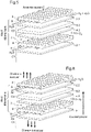
figure 5 est une vue schématique en éclaté d'une partie d'un électrolyseur à haute température comprenant des interconnecteurs selon l'état de l'art, - la
figure 6 est une vue schématique en éclaté d'une partie d'une pile à combustible SOFC comprenant des interconnecteurs selon l'état de l'art, - la
figure 7 est une vue en coupe schématique d'un interconnecteur revêtu selon l'invention, - la
figure 8 est une reproduction photographique d'un exemple de couche épaisse en céramique rainurée et thermocollée sur un substrat en alliage ferritique conformément à l'invention, - la
figure 8A est une vue en coupe schématique de lafigure 8 montrant les dimensions considérées des canaux de la couche épaisse en céramique, - la
figure 9 montre les courbes représentatives de la géométrie de rainures (sillons) obtenues par ablation laser au CO2 sur une couche épaisse en céramique, - la
figure 10 montre la variation de profils des rainures montrées enfigure 9 avant et après essai sous une charge de compression et à une température de 800°C, - les
figures 11A et 11B sont des reproductions photographiques d'une couche épaisse en céramique avant et après essai sous une charge de compression et à une température de 800°C, - la
figure 12 illustre les courbes de mesure de résistance série de différentes couches épaisses en céramique selon l'invention et à titre comparatifs de grilles en or, les couches et grille en or étant en contact avec un substrat en alliage métallique.
- the
figure 1 is a schematic front view of an interconnecting plate of an EHT electrolyser according to the state of the art, - the
Figure 1A is a detail view in section of an interconnecting plate according to thefigure 1 , - the
figure 1B is a view analogous toFigure 1A showing the streamlines traversing the plate, - the
figure 2 is a schematic front view of another interconnecting plate of an electrolyser according to the state of the art, - the
picture 3figure 1 , obtained by mechanical machining, - the
figure 4 is a photographic reproduction of a plate according to thefigure 1 , obtained by stamping, - the
figure 5 is an exploded schematic view of part of a high temperature electrolyser comprising interconnectors according to the state of the art, - the
figure 6 is an exploded schematic view of part of a SOFC fuel cell comprising interconnectors according to the state of the art, - the
figure 7 is a schematic sectional view of a coated interconnector according to the invention, - the
figure 8 is a photographic reproduction of an example of a thick ceramic layer grooved and thermally bonded to a ferritic alloy substrate in accordance with the invention, - the
figure 8A is a schematic sectional view of thefigure 8 showing the considered dimensions of the channels of the ceramic thick layer, - the
figure 9 shows the representative curves of the geometry of grooves (furrows) obtained by CO2 laser ablation on a thick ceramic layer, - the
figure 10 shows the variation of profiles of the grooves shown infigure 9 before and after test under a compressive load and at a temperature of 800°C, - them
figures 11A and 11B are photographic reproductions of a thick ceramic layer before and after testing under a compressive load and at a temperature of 800°C, - the
figure 12 illustrates the series resistance measurement curves of different thick ceramic layers according to the invention and by way of comparison of gold grids, the gold layers and grid being in contact with a metal alloy substrate.
Les
La
Dans un électrolyseur EHT, un interconnecteur 8 est un composant en alliage métallique qui assure la séparation entre les compartiments anodique 7 et cathodique 9, définis par les volumes compris entre l'interconnecteur 8 et l'anode adjacente 4.2 et entre l'interconnecteur 8 et la cathode adjacente 2.1 respectivement. Il assure également la distribution des gaz aux cellules. L'injection de vapeur d'eau dans chaque motif élémentaire se fait dans le compartiment cathodique 9. Le collectage de l'hydrogène produit et de la vapeur d'eau résiduelle à la cathode 2.1, 2.2 est effectué dans le compartiment cathodique 9 en aval de la cellule C1,C2 après dissociation de la vapeur d'eau par celle-ci. Le collectage de l'oxygène produit à l'anode 4.2 est effectué dans le compartiment anodique 7 en aval de la cellule C1, C2 après dissociation de la vapeur d'eau par celle-ci.In an EHT electrolyser, an
L'interconnecteur 8 assure le passage du courant entre les cellules C1 et C2 par contact direct avec les électrodes adjacentes, c'est-à-dire entre l'anode 4.2 et la cathode 2.1 (
La
L'injection de l'air contenant l'oxygène dans chaque motif élémentaire se fait dans le compartiment cathodique 9. Le collectage de l'eau produit à la cathode 2.1, 2.2 est effectué dans le compartiment cathodique 9 en aval de la cellule C1,C2. après recombinaison de l'eau par celle-ci avec l'hydrogène H2 injecté à l'anode 4.2 est effectué dans le compartiment anodique 7 en amont de la cellule C1, C2. Le courant produit lors de la recombinaison de l'eau est collecté par les interconnecteurs 8.The injection of the air containing the oxygen into each elementary pattern takes place in the
Selon l'état de l'art, ces interconnecteurs 8 sont usuellement réalisés par usinage mécanique de plaques épaisses ou par emploi de tôles minces, typiquement de 0,5 à 2 mm, embouties puis assemblées entre elles par soudage laser. Les coûts de matière et d'usinage sont importants. La technique de réalisation a pour avantage de limiter le coût de matière première mais ne permet pas d'atteindre une finesse de canaux aussi élevée que par usinage. De fait, les possibilités de réalisation pour la profondeur des canaux, la largeur unitaire de dent et le pas entre dents sont limitées. De plus, le coût de l'outillage d'emboutissage nécessite une production en grande série. En outre, le contact électrique entre les électrodes et l'interconnecteur n'est pas complètement satisfaisant en particulier du fait du défaut de planéité des électrodes.According to the state of the art, these
Aussi, pour simplifier les techniques de réalisation des interconnecteurs pour piles à combustible SOFC ou électrolyseur EHT et les rendre moins coûteuses, les inventeurs proposent un nouveau type d'interconnecteur 8 dont un exemple est représenté en
Le composant 8 constituant le nouvel interconnecteur selon l'invention, comporte un substrat 82 en alliage métallique dont l'élément de base est du Fer (Fe) ou du Nickel (Ni), le substrat ayant deux faces planes principales, l'une des faces planes principales étant revêtue d'un revêtement comportant une couche épaisse en céramique 80 et l'autre des faces planes principales étant revêtue d'une couche épaisse métallique 81, chacune des couches épaisses étant rainurée en délimitant des canaux 800, 810 adaptés pour la distribution et/ou la collecte de gaz, tels que vapeur d'eau H2O, gaz drainant, Air, O2, H2.
Eventuellement, une couche mince de protection en céramique 83 peut être intercalée entre la couche épaisse 80 en céramique et le substrat 82.Optionally, a thin ceramic
En fonctionnement dans un électrolyseur EHT ou une pile à combustible SOFC, les conditions d'utilisation sont les mêmes que celles classiquement utilisées : la circulation d'un mélange gazeux réducteur est faite dans les canaux 810 de la couche métallique épaisse 81 et celle d'un mélange gazeux oxydant est faire dans les canaux 800 de la couche céramique épaisse 80.In operation in an EHT electrolyser or a SOFC fuel cell, the conditions of use are the same as those conventionally used: the circulation of a reducing gaseous mixture is made in the
On décrit ci-après les différentes étapes de réalisation d'un exemple d'une couche épaisse 80 en céramique avec ses canaux 800 et différents essais prouvant la possibilité de son utilisation dans les applications visées, i.e. piles à combustibles SOFC et électrolyseur EHT.The various stages of production of an example of a thick
L'exemple ci-après est fait à partir d'un substrat 82 constitué d'une seule tôle mince en alliage ferritique commercial du type CROFER 22 APU.The example below is made from a
On réalise le mélange entre un composé d'un poids de 60 g de manganite de lanthane de formule La0,8Sr0,2MnO3 avec 0,8% en poids d'acide oléique en tant que dispersant, 15,7% de 2-butanone et 15,7% d'éthanol en tant que solvants.The mixture is made between a compound weighing 60 g of lanthanum manganite of formula La 0.8 Sr 0.2 MnO 3 with 0.8% by weight of oleic acid as dispersant, 15.7% of 2-butanone and 15.7% ethanol as solvents.
Le mélange est broyé dans un broyeur de type planétaire. Le cycle de fonctionnement du broyeur planétaire est le suivant :
- vitesse de rotation : 400 tours par minute ;
- durée : 1 heure.
- rotational speed: 400 revolutions per minute;
- duration: 1 hour.
On effectue alors un ajout, dans le mélange broyé, d'un poids de 3,2g de polyvinyle de butyral (PVB 90), et de 5,5g de polyéthylène glycol (PEG 400) en tant que solvant puis on mélange le tout à l'aide d'un broyeur de type planétaire. Le cycle de fonctionnement du broyeur de type planétaire est le suivant :
- vitesse de rotation : 200 tours par minute ;
- durée : 10 heures.
- rotation speed: 200 revolutions per minute;
- duration: 10 hours.
On effectue ensuite une désaération du mélange à l'aide d'un mélangeur de type à rouleaux. Le cycle de fonctionnement du mélangeur à rouleaux est le suivant :
- vitesse de rotation : 20 tours par minute ;
- durée : 24 heures.
- rotation speed: 20 revolutions per minute;
- duration: 24 hours.
On réalise alors le coulage en bande de la suspension obtenue après désaération à l'aide d'un couteau racleur. La hauteur active du couteau est égale à 1000µm. La vitesse de coulage est égale à 1,5 m/mn. Le coulage s'effectue sur une feuille de polymère (polyester) siliconé afin de favoriser le décollement de la bande une fois séchée.The suspension obtained after deaeration is then cast in a strip using a scraper knife. The active height of the knife is equal to 1000µm. The casting speed is equal to 1.5 m/min. Casting is carried out on a sheet of silicone polymer (polyester) in order to promote the detachment of the strip once dried.
Puis, on effectue le séchage de la bande crue obtenue par coulage, à l'air ambiant pendant une durée de 3h.Then, the raw strip obtained by casting is dried in ambient air for a period of 3 hours.
La bande crue séchée de LSM est enfin découpée à des dimensions correspondantes à une électrode à air dans une pile SOFC, contre laquelle la bande est destinée à venir s'appuyer. La découpe peut par exemple être réalisée à l'aide d'une table de découpe laser.The raw, dried strip of LSM is finally cut to dimensions corresponding to an air electrode in a SOFC stack, against which the strip is intended to rest. The cutting can for example be carried out using a laser cutting table.
La bande crue de LSM est ensuite déposée sur une tôle mince d'acier ferritique de 1.5 mm d'épaisseur puis elle est soudée par à celle-ci par thermopressage à l'aide d'une presse. L'épaisseur de la bande crue de LSM est de 325 µm. Dans le cas où la couche mince céramique de protection 83 est ajoutée, on procède de manière identique.The raw strip of LSM is then deposited on a thin sheet of ferritic steel 1.5 mm thick and then it is welded to it by thermopressing using a press. The thickness of the green LSM strip is 325 μm. In the case where the thin ceramic
Le cycle de fonctionnement de la presse est le suivant :
- force de pressage : 1kg/mm2 ;
- durée d'application du pressage : 2h ;
- température régulée des deux plateaux de presse : 80°C.
- pressing force: 1kg/ mm2 ;
- pressing time: 2 hours;
- regulated temperature of the two press plates: 80°C.
Après refroidissement à la température ambiante, l'assemblage réalisé entre bande crue de LSM et tôle mince d'acier ferritique est retiré de la presse.After cooling to ambient temperature, the assembly produced between a raw strip of LSM and a thin sheet of ferritic steel is removed from the press.
On réalise un rainurage par ablation laser de la bande crue de LSM. L'ablation est réalisé à l'aide d'une table traçante équipée d'un laser au CO2 d'une puissance variable jusqu'à la puissance maximale de 50 Watt. La vitesse de déplacement du laser est également variable, jusqu'à la vitesse maximale de 2 cm/s. L'utilisation d'un tel appareil est particulièrement avantageuse car il permet par ses caractéristiques variables de fonctionnement de brûler, c'est-à-dire réaliser une abrasion, plus ou moins en profondeur les polymères constituant la bande crue, ce qui libère ainsi la charge associée, le LSM. On peut ainsi creuser des rainures (sillons) plus ou moins profondes. Le cas échéant, plusieurs passages du laser au CO2 sur la bande crue peuvent être effectués pour augmenter plus ou moins la profondeur et/ou la largeur des rainures.Grooving is carried out by laser ablation of the green band of LSM. The ablation is performed using a plotter equipped with a CO 2 laser with variable power up to the maximum power of 50 Watt. The speed of movement of the laser is also variable, up to the maximum speed of 2 cm/s. The use of such a device is particularly advantageous because it allows by its variable operating characteristics to burn, that is to say to carry out an abrasion, more or less in depth the polymers constituting the raw strip, which thus releases the associated load, the LSM. It is thus possible to dig more or less deep grooves (furrows). If necessary, several passages of the CO 2 laser on the raw strip can be carried out to increase more or less the depth and/or the width of the grooves.
La
On a représenté en
On précise ici que le zéro de la hauteur correspond à l'interface avec la tôle mince d'acier ferritique et que chacune des géométries a été obtenue en réglant la vitesse de déplacement du laser à une valeur égale à 40% de la vitesse maximale indiquée ci-avant et la puissance à une valeur égale à 50% de la puissance maximale indiquée ci-avant (50W).It is specified here that the zero of the height corresponds to the interface with the thin sheet of ferritic steel and that each of the geometries was obtained by adjusting the speed of movement of the laser to a value equal to 40% of the maximum speed indicated. above and the power at a value equal to 50% of the maximum power indicated above (50W).
Lors de son utilisation, c'est-à-dire lorsqu'il constitue un interconnecteur dans un empilement soit d'un réacteur d'électrolyse à l'eau à haute température (EHT) soit d'une pile à combustible SOFC, le composant métallique revêtu de la couche épaisse de LSM obtenue dans l'exemple décrit ci-avant est mis sous charge de compression dans l'empilement afin d'assurer le contact électrique avec les autres éléments de l'empilement et en particulier la cathode d'une pile SOFC. D'autre part, dans des conditions d'EHT, il peut subir des températures élevées comprises entre 600°C et 900°C.During its use, that is to say when it constitutes an interconnector in a stack either of a high temperature water electrolysis reactor (EHT) or of a SOFC fuel cell, the component metal coated with the thick layer of LSM obtained in the example described above is placed under a compression load in the stack in order to ensure electrical contact with the other elements of the stack and in particular the cathode of a SOFC stack. On the other hand, under EHT conditions, it can experience high temperatures between 600°C and 900°C.
Pour valider le bon comportement thermomécanique sous effort de compression, on a réalisé un essai selon lequel on a mis la couche de LSM à une température de 800°C et sous une charge de 0,2 MPa.To validate the good thermomechanical behavior under compressive stress, a test was carried out in which the LSM layer was placed at a temperature of 800° C. and under a load of 0.2 MPa.
La
Les
En outre, on a réalisé des mesures de la résistance série avec le composant en alliage métallique pour caractériser la conductivité électrique de la couche de LSM obtenue dans des conditions de fonctionnement représentatives simulant l'entrée de compartiments cathodiques 9 d'une pile SOFC. La méthode de mesure utilisée est la méthode dite des quatre points, telle qu'explicitée dans la publication [8].In addition, series resistance measurements were performed with the metal alloy component to characterize the electrical conductivity of the LSM layer obtained under representative operating conditions simulating the inlet of
Pour ce faire, on a réalisé plusieurs échantillons tous à partir d'un composant en acier inoxydable, les échantillons selon l'invention N°1 à 4 étant constitués par un assemblage du composant avec une couche de LSM par thermopressage, les échantillons comparatifs N°5 à 6 étant constitués par un assemblage du composant avec une grille d'or.To do this, several samples were all made from a stainless steel component, the samples according to the invention Nos. 1 to 4 being constituted by an assembly of the component with a layer of LSM by thermopressing, the comparative samples N °5 to 6 being constituted by an assembly of the component with a gold grid.
On précise que dans l'échantillon N°l, la couche de LSM est dépourvue de canaux tandis que dans les échantillons N°2 à 4, la couche de LSM est rainurée en définissant des canaux identiques de largeur unitaire L1 égale à 1 mm, deux canaux adjacents étant espacés d'une dent ou nervure de largeur unitaire L2 égale à 0,25 mm.It is specified that in sample No. 1, the LSM layer has no channels while in samples No. 2 to 4, the LSM layer is grooved by defining identical channels of unit width L1 equal to 1 mm, two adjacent channels being spaced apart by a tooth or rib of unit width L2 equal to 0.25 mm.
La
De ces mesures, on en déduit que les résistances série sont quasiment identiques entre tous les échantillons N°1 à 6. On peut donc en conclure que la résistance de contact d'une couche épaisse de LSM selon l'invention est proche voire égale à une grille d'or qui est l'élément mécanique connu à ce jour comme ayant la résistance de contact la plus faible. Autrement dit, une couche de LSM selon l'invention présente une résistance électrique de contact négligeable, inférieure à 10 mΩ.cm2.From these measurements, it can be deduced that the series resistances are almost identical between all samples Nos. 1 to 6. It can therefore be concluded that the contact resistance of a thick layer of LSM according to the invention is close to or even equal to a gold grid which is the mechanical element known to date as having the lowest contact resistance. In other words, an LSM layer according to the invention has a negligible electrical contact resistance, less than 10 mΩ.cm 2 .
D'autres essais de mesure ont été réalisés au-delà de 24heures mais avec un empilement de cellules électrochimiques, d'interconnecteurs selon l'invention et des contacts. Ces essais ont été satisfaisants.Other measurement tests were carried out beyond 24 hours but with a stack of electrochemical cells, interconnectors according to the invention and contacts. These tests were satisfactory.
L'obtention d'une couche métallique épaisse selon l'invention sur la face d'un substrat métallique opposée à celle comportant la couche céramique épaisse peut être effectuée de manière similaire à ce qui vient d'être décrit, i.e. avec coulage en bande, suivi d'un thermopressage et de réalisation de rainures par ablation au moyen d'un laser au CO2.Obtaining a thick metallic layer according to the invention on the face of a metallic substrate opposite to that comprising the thick ceramic layer can be carried out in a manner similar to what has just been described, ie with strip casting, followed by thermopressing and creation of grooves by ablation using a CO 2 laser.
L'invention n'est pas limitée aux exemples qui viennent d'être décrits ; on peut notamment combiner entre elles des caractéristiques des exemples illustrés au sein de variantes non illustrées.The invention is not limited to the examples which have just been described; it is in particular possible to combine together characteristics of the examples illustrated within variants not illustrated.
-
[1].
J.W. Fergus, "Metallic interconnects for solid oxide fuel cells", Mater. Sci. Eng. A 397 (2005) 271-283 JW Fergus, "Metallic interconnects for solid oxide fuel cells", Mater. Science. Eng. A 397 (2005) 271-283 -
[2].
W.J. Quadakkers, J. Piron-Abellan, V. Shemet, L. Singheiser, "Metallic interconnectors for solid oxide fuel cells - a review", Mat. High Temp. 20 (2) (2003) 115-127 WJ Quadakkers, J. Piron-Abellan, V. Shemet, L. Singheiser, "Metallic interconnectors for solid oxide fuel cells - a review", Mat. High Temp. 20(2)(2003) 115-127 -
[3].
Z. Yang, K. Scott Weil, D.M. Paxton, J.W. Stevenson, "Selection and Evaluation of Heat-Resistant Alloys for SOFC Interconnect Applications", J. Electrochem. Soc. 150 (9) (2003) A1188-A1201 Z. Yang, K. Scott Weil, DM Paxton, JW Stevenson, "Selection and Evaluation of Heat-Resistant Alloys for SOFC Interconnect Applications", J. Electrochem. Soc. 150 (9) (2003) A1188-A1201 -
[4].:
J.E. Hammer, S.J. Laney, R.W. Jackson, K. Coyne, F.S. Pettit, G.H. Meier, "The Oxidation of Ferritic Stainless Steels in Simulated Solid-Oxide Fuel-Cell Atmospheres, Oxid. Met". 67(1/2) (2007) 1-38 JE Hammer, SJ Laney, RW Jackson, K. Coyne, FS Pettit, GH Meier, "The Oxidation of Ferritic Stainless Steels in Simulated Solid-Oxide Fuel-Cell Atmospheres, Oxid. Met". 67(1/2) (2007) 1-38 -
[5].
S.J. Geng et al., "Investigation on Haynes 242 Alloy as SOFC Interconnect in Simulated Anode Environment », Electrochemical and Solid-State Letters, 9 (4) (2006) A211-A214 SJ Geng et al., "Investigation on Haynes 242 Alloy as SOFC Interconnect in Simulated Anode Environment", Electrochemical and Solid-State Letters, 9 (4) (2006) A211-A214 -
[6].
N. Shaigan et al., "A review of recent progress in coatings, surface modifications and alloy developments for solid oxide fuel cell ferritic stainless steel interconnects », J. Power Sources 195 (2010) 1529-1542 N. Shaigan et al., "A review of recent progress in coatings, surface modifications and alloy developments for solid oxide fuel cell ferritic stainless steel interconnects", J. Power Sources 195 (2010) 1529-1542 -
[7].
Xiango Li, International Journal of hydrogen Energy 30 (2005) 359-371 Xiango Li, International Journal of hydrogen Energy 30 (2005) 359-371 -
[8].
S. Fontana, R. Amendola, S. Chevalier, P. Piccardo, G. Caboche, M. Viviani, R. Molins, M. Sennour, "Metallic interconnects for SOFC: Characterisation of corrosion resistance and conductivity evaluation at operating temperature of differently coated alloys", J. Power Sources 171 (2007) 652-662 S. Fontana, R. Amendola, S. Chevalier, P. Piccardo, G. Caboche, M. Viviani, R. Molins, M. Sennour, "Metallic interconnects for SOFC: Characterization of corrosion resistance and conductivity evaluation at operating temperature of differently coated alloys", J. Power Sources 171 (2007) 652-662 -
[9].
Maria Rosa ARDIGO, "Optimisation d'interconnecteurs métalliques pour la production d'hydrogène par électrolyse de la vapeur d'eau à haute température (EVHT)", Thèse de doctorat soutenue le 09 Septembre 2012, http://nuxeo.u-bourgogne.fr/nuxeo/site/esupversions/9a356817-2ef1-4b4e-863e-8fa66b4c4a73 Maria Rosa ARDIGO, "Optimization of metallic interconnectors for the production of hydrogen by electrolysis of high temperature water vapor (EVHT)", Doctoral thesis defended on September 09, 2012, http://nuxeo.u-bourgogne .fr/nuxeo/site/esupversions/9a356817-2ef1-4b4e-863e-8fa66b4c4a73
Claims (19)
- Component (8) constituting an interconnector of a fuel cell or of a high-temperature electrolyser, including a substrate made of metal alloy (82), of chromia-forming type, the base element of which is iron (Fe) or nickel (Ni), the substrate having two main flat faces, one of the main flat faces being coated with a coating including a thick ceramic layer (80) in a green state, said thick ceramic layer (80) being grooved, delimiting channels (800) that are suitable for distributing and/or collecting gases, such as H2O steam, H2, air.
- Component (8) constituting an interconnector of a fuel cell or of a high-temperature electrolyser, including a substrate made of metal alloy (82), of chromia-forming type, the base element of which is iron (Fe) or nickel (Ni), the substrate having two main flat faces, one of the main flat faces being coated with a thick metallic layer (81) in a green state, said thick metallic layer (81) being grooved, delimiting channels (810) that are suitable for distributing and/or collecting gases, such as H2O steam, H2; O2, draining gas.
- Component according to Claim 1 in combination with Claim 2, one of the main flat faces being coated with a coating including a thick ceramic layer and the other of the main flat faces being coated with a thick metallic layer, each of the thick layers being grooved, delimiting channels that are suitable for distributing and/or collecting gases, such as H2O steam, draining gas, air, O2, H2.
- Component according to one of Claims 1 or 3, the material of the thick ceramic layer being chosen from a lanthanum manganite of formula La1-xSrxMO3 with M (transition metals) = Ni, Fe, Co, Mn, Cr, alone or as a mixture, or materials of lamellar structure such as lanthanide nickelates of formula Ln2NiO4 (Ln= La, Nd, Pr), or another electrically conductive perovskite oxide.
- Component according to one of Claims 2 to 4, the material of the thick metallic layer being chosen from nickel (Ni) and alloys thereof and also all the chromia-forming alloys whose base element is iron (Fe).
- Component according to one of the preceding claims, the thickness of the ceramic layer being between 60 and 500 µm.
- Component according to one of the preceding claims, the chromia-forming metal alloy of the substrate being chosen from ferritic (Fe-Cr), austenitic (Ni-Fe-Cr) stainless-steel alloys or superalloys based on nickel forming at the surface a layer of chromium oxide Cr2O3, known as the chromia layer.
- Component according to one of the preceding claims, the substrate consisting of at least one thin sheet or of a single plate with flat main faces.
- Component according to one of Claims 3 to 9, consisting of an interconnector of a high-temperature electrolysis (HTE) reactor including a stack of elementary electrolysis cells each formed from a cathode, an anode and an electrolyte intercalated between the cathode and the anode, the thick grooved ceramic layer being in contact with the anode of one of two adjacent elementary cells, the thick grooved metallic layer being in contact with the cathode of the other of the two adjacent elementary cells.
- Component according to one of Claims 3 to 9, constituting an interconnector of a fuel cell (SOFC) including a stack of elementary cells each formed from a cathode, an anode and an electrolyte intercalated between the cathode and the anode, the thick grooved ceramic layer being in contact with the cathode of one of two adjacent elementary cells, the thick grooved metallic layer being in contact with the anode of the other of the two adjacent elementary cells.
- Component according to one of the preceding claims, the width of the channels being between 0.15 and 5 mm.
- Component according to one of the preceding claims, the depth of the channels being between 0.1 and 0.5 mm.
- Process for preparing a component intended to constitute an interconnector for a fuel cell (SOFC) or a high-temperature electrolyser (HTE), including the following steps:a/ preparing a substrate made of metal alloy (8), of chromia-forming type, the base element of which is iron (Fe) or nickel (Ni), the substrate having two main flat faces,b1/ coating one of the flat faces of the substrate with a thick ceramic layer in a green state;c1/ grooving the thick ceramic layer so as to delimit channels that are suitable for distributing and/or collecting gases, such as H2O steam, H2; air.
- Process for preparing a component, intended to constitute an interconnector for a fuel cell (SOFC) or a high-temperature electrolyser (HTE), including the following steps:a/ preparing a substrate made of metal alloy (8), of chromia-forming type, the base element of which is iron (Fe) or nickel (Ni), the substrate having two main flat faces,b2/ coating one of the flat faces of the substrate with a thick metallic layer in a green state;c2/ grooving the thick metallic layer so as to delimit channels that are suitable for distributing and/or collecting gases, such as H2O steam, H2; air.
- Process according to either of Claims 13 and 14, steps b1/ and c1/ being performed on one flat face of the substrate, steps b2/ and c2/ being performed on the other flat face of the substrate.
- Process according to one of Claims 13 to 15, in which, prior to step b1/ and/or step b2/, the thick ceramic or metallic layer is obtained by tape casting, step b1/ and/or b2/ consisting of hot-bonding or hot-pressing or chemical bonding of the tape to one or other of the faces of the substrate.
- Process according to Claim 16, step c1/ being performed by calendaring the green ceramic tape obtained by casting between two rolls heated to the softening point of the polymers of the ceramic tape, at least one of the two rolls including ribs corresponding to the channels to be delimited, step b1/ being performed after step c1/.
- Process according to one of Claims 13 to 15, step b1/ and/or b2/ consisting of screen printing in thick layers of a ceramic or metallic paste onto one or other of the faces of the substrate.
- Process according to one of Claims 13 to 18, step c1/ and/or c2/ being performed by laser ablation once step b1/ and/or b2/, respectively, has been completed.
Applications Claiming Priority (2)
| Application Number | Priority Date | Filing Date | Title |
|---|---|---|---|
| FR1259040A FR2996065B1 (en) | 2012-09-26 | 2012-09-26 | COMPONENT COMPRISING AN EHT ELECTROLYSER INTERCONNECTOR OR SOFC FUEL CELL AND METHODS OF MAKING SAME |
| PCT/IB2013/058814 WO2014049523A1 (en) | 2012-09-26 | 2013-09-24 | Component constituting an hte electrolyser interconnector or sofc fuel cell interconnector and associated production processes |
Publications (2)
| Publication Number | Publication Date |
|---|---|
| EP2900846A1 EP2900846A1 (en) | 2015-08-05 |
| EP2900846B1 true EP2900846B1 (en) | 2022-08-17 |
Family
ID=47428668
Family Applications (1)
| Application Number | Title | Priority Date | Filing Date |
|---|---|---|---|
| EP13801780.1A Active EP2900846B1 (en) | 2012-09-26 | 2013-09-24 | Component constituting an hte electrolyser interconnector or sofc fuel cell interconnector and associated production processes |
Country Status (10)
| Country | Link |
|---|---|
| US (2) | US20150218713A1 (en) |
| EP (1) | EP2900846B1 (en) |
| JP (1) | JP6476119B2 (en) |
| KR (1) | KR20150064046A (en) |
| AU (1) | AU2013322252B2 (en) |
| CA (1) | CA2885138C (en) |
| DK (1) | DK2900846T3 (en) |
| FR (1) | FR2996065B1 (en) |
| WO (1) | WO2014049523A1 (en) |
| ZA (1) | ZA201502274B (en) |
Families Citing this family (12)
| Publication number | Priority date | Publication date | Assignee | Title |
|---|---|---|---|---|
| NO343985B1 (en) * | 2017-07-03 | 2019-08-05 | Sintef Tto As | Polymer electrolyte membrane (PEM) water electrolyser cell, stack and system and a method for producing hydrogen in said PEM water electrolyser system |
| US11557781B2 (en) | 2018-09-05 | 2023-01-17 | Battelle Energy Alliance, Llc | Electrochemical cells for hydrogen gas production and electricity generation, and related systems and methods |
| FR3104324B1 (en) * | 2019-12-10 | 2021-12-03 | Commissariat A L Energie Atomique Et Aux Energies Alternatives | Improved method of making a component constituting an EHT electrolyzer or SOFC fuel cell interconnector. |
| FR3113443B1 (en) | 2020-08-11 | 2022-09-23 | Commissariat Energie Atomique | Electrolysis or co-electrolysis reactor (SOEC) or fuel cell (SOFC) with stacking of electrochemical cells by pre-assembled modules, associated production method. |
| JP7520742B2 (en) * | 2021-02-03 | 2024-07-23 | 東芝エネルギーシステムズ株式会社 | Interconnector with protective layer, cell stack and fuel cell including said interconnector with protective layer |
| FR3122779B1 (en) | 2021-05-04 | 2023-11-03 | Commissariat Energie Atomique | Process for producing a SOEC/SOFC type solid oxide stack and associated stack |
| FR3127640B1 (en) | 2021-09-29 | 2023-10-27 | Commissariat Energie Atomique | Interconnector for stacking SOEC/SOFC type solid oxide cells with optimized geometry tabs |
| FR3127639B1 (en) | 2021-09-29 | 2023-10-27 | Commissariat Energie Atomique | Interconnector for stacking of SOEC/SOFC type solid oxide cells comprising different raised elements |
| FR3127850A1 (en) | 2021-10-05 | 2023-04-07 | Commissariat A L'energie Atomique Et Aux Energies Alternatives | System for conditioning a plurality of stacks of superposed SOEC/SOFC type solid oxide cells at high temperature |
| FR3129533A1 (en) | 2021-11-23 | 2023-05-26 | Commissariat A L'energie Atomique Et Aux Energies Alternatives | System for conditioning a plurality of stacks of SOEC/SOFC type solid oxide cells at high temperature |
| FR3133947B1 (en) | 2022-03-22 | 2024-02-09 | Commissariat Energie Atomique | System for conditioning a plurality of superimposed sub-stacks of solid oxide cells of the SOEC/SOFC type at high temperature |
| FR3143634A1 (en) | 2022-12-20 | 2024-06-21 | Commissariat A L'energie Atomique Et Aux Energies Alternatives | Interconnector for stacking of SOEC/SOFC type solid oxide cells comprising a perforated contact layer |
Citations (6)
| Publication number | Priority date | Publication date | Assignee | Title |
|---|---|---|---|---|
| EP0338823A1 (en) * | 1988-04-21 | 1989-10-25 | Toa Nenryo Kogyo Kabushiki Kaisha | Solid electrolyte type fuel cells |
| WO1996028855A1 (en) * | 1995-03-15 | 1996-09-19 | Ceramic Fuel Cells Limited | Fuel cell interconnect device |
| US20030231973A1 (en) * | 2002-06-12 | 2003-12-18 | The University Of Chicago | Compositionally graded metallic plates for planar solid oxide fuel cells |
| US20060285993A1 (en) * | 2005-06-15 | 2006-12-21 | Rakowski James M | Interconnects for solid oxide fuel cells and ferritic stainless steels adapted for use with solid oxide fuel cells |
| US20090214926A1 (en) * | 2005-06-17 | 2009-08-27 | University Of Yamanashi | Metal Separator For Fuel Cell and Manufacturing Method Thereof |
| US8546046B2 (en) * | 2009-11-20 | 2013-10-01 | Industrial Technology Research Institute | Method for fabricating bi-polar plate of fuel cell and bi-polar plate of fuel cell |
Family Cites Families (22)
| Publication number | Priority date | Publication date | Assignee | Title |
|---|---|---|---|---|
| JP2604437B2 (en) * | 1987-10-15 | 1997-04-30 | 東燃株式会社 | High-temperature fuel cell interelectrode assembly and high-temperature fuel cell cathode current collector |
| JPH02177265A (en) * | 1988-11-28 | 1990-07-10 | Tonen Corp | Solid electrolyte for fuel cell |
| US5376472A (en) * | 1993-10-06 | 1994-12-27 | Ceramatec, Inc. | Semi-internally manifolded interconnect |
| AUPN876896A0 (en) * | 1996-03-18 | 1996-04-18 | Ceramic Fuel Cells Limited | An electrical interconnect for a planar fuel cell |
| US6326096B1 (en) * | 1998-02-04 | 2001-12-04 | Gas Research Institute | Solid oxide fuel cell interconnector |
| US6054231A (en) * | 1998-07-24 | 2000-04-25 | Gas Research Institute | Solid oxide fuel cell interconnector |
| US6106967A (en) | 1999-06-14 | 2000-08-22 | Gas Research Institute | Planar solid oxide fuel cell stack with metallic foil interconnect |
| US20020004155A1 (en) * | 2000-05-01 | 2002-01-10 | Haltiner Karl Jacob | Etched interconnect for fuel cell elements |
| US6770395B2 (en) | 2000-10-23 | 2004-08-03 | Materials And Systems Research, Inc. | Internally manifolded, planar solid oxide fuel cell (SOFC) stack with an inexpensive interconnect |
| CA2437891A1 (en) * | 2001-02-12 | 2002-08-22 | The Morgan Crucible Company Plc | Flow field plate geometries |
| US6653009B2 (en) * | 2001-10-19 | 2003-11-25 | Sarnoff Corporation | Solid oxide fuel cells and interconnectors |
| US7595122B2 (en) * | 2002-06-11 | 2009-09-29 | General Electric Company | Interconnect supported electrolyzer assembly, preform and method of fabrication |
| US20040200187A1 (en) | 2002-11-27 | 2004-10-14 | Warrier Sunil G. | Compliant, strain tolerant interconnects for solid oxide fuel cell stack |
| WO2004083472A2 (en) * | 2003-03-18 | 2004-09-30 | Liquidmetal Technologies, Inc. | Current collector plates of bulk-solidifying amorphous alloys |
| DE102004013791B4 (en) * | 2004-03-20 | 2009-09-24 | Forschungszentrum Jülich GmbH | Electrically conductive steel-ceramic composite and its manufacture and use |
| AU2006259739B2 (en) * | 2005-06-15 | 2011-09-08 | Ati Properties, Inc. | Interconnects for solid oxide fuel cells and ferritic stainless steels adapted for use with solid oxide fuel cells |
| US7581259B2 (en) * | 2005-06-23 | 2009-09-01 | Joe Thompson | Chair blanket, and method for covering chair occupant |
| US7736788B2 (en) * | 2005-08-12 | 2010-06-15 | Nanyang Technological University | Pattern molding of polymeric flow channels for micro fuel cells |
| US7645535B2 (en) | 2005-11-14 | 2010-01-12 | General Electric Company | Method and materials for bonding electrodes to interconnect layers in solid oxide fuel cell stacks |
| US20090162706A1 (en) * | 2006-03-07 | 2009-06-25 | Kyocera Corporation | Method for Manufacturing Ceramic Member, and Ceramic Member, Gas Sensor Device, Fuel Cell Device, Multi-Layer Piezoelectric Device, Injection Apparatus and Fuel Injection System |
| DK1930974T3 (en) * | 2006-11-23 | 2012-07-09 | Univ Denmark Tech Dtu | Process for the preparation of reversible solid oxide cells |
| WO2010085248A1 (en) | 2009-01-22 | 2010-07-29 | Utc Power Corporation | Solid oxide fuel cell having metal support with a compliant porous nickel layer |
-
2012
- 2012-09-26 FR FR1259040A patent/FR2996065B1/en active Active
-
2013
- 2013-09-24 KR KR1020157008018A patent/KR20150064046A/en not_active Application Discontinuation
- 2013-09-24 EP EP13801780.1A patent/EP2900846B1/en active Active
- 2013-09-24 US US14/429,610 patent/US20150218713A1/en not_active Abandoned
- 2013-09-24 DK DK13801780.1T patent/DK2900846T3/en active
- 2013-09-24 CA CA2885138A patent/CA2885138C/en active Active
- 2013-09-24 JP JP2015533739A patent/JP6476119B2/en active Active
- 2013-09-24 AU AU2013322252A patent/AU2013322252B2/en not_active Ceased
- 2013-09-24 WO PCT/IB2013/058814 patent/WO2014049523A1/en active Application Filing
-
2015
- 2015-04-07 ZA ZA2015/02274A patent/ZA201502274B/en unknown
-
2020
- 2020-02-24 US US16/799,220 patent/US11078579B2/en active Active
Patent Citations (6)
| Publication number | Priority date | Publication date | Assignee | Title |
|---|---|---|---|---|
| EP0338823A1 (en) * | 1988-04-21 | 1989-10-25 | Toa Nenryo Kogyo Kabushiki Kaisha | Solid electrolyte type fuel cells |
| WO1996028855A1 (en) * | 1995-03-15 | 1996-09-19 | Ceramic Fuel Cells Limited | Fuel cell interconnect device |
| US20030231973A1 (en) * | 2002-06-12 | 2003-12-18 | The University Of Chicago | Compositionally graded metallic plates for planar solid oxide fuel cells |
| US20060285993A1 (en) * | 2005-06-15 | 2006-12-21 | Rakowski James M | Interconnects for solid oxide fuel cells and ferritic stainless steels adapted for use with solid oxide fuel cells |
| US20090214926A1 (en) * | 2005-06-17 | 2009-08-27 | University Of Yamanashi | Metal Separator For Fuel Cell and Manufacturing Method Thereof |
| US8546046B2 (en) * | 2009-11-20 | 2013-10-01 | Industrial Technology Research Institute | Method for fabricating bi-polar plate of fuel cell and bi-polar plate of fuel cell |
Also Published As
| Publication number | Publication date |
|---|---|
| US20200208275A1 (en) | 2020-07-02 |
| US11078579B2 (en) | 2021-08-03 |
| CA2885138C (en) | 2021-09-14 |
| EP2900846A1 (en) | 2015-08-05 |
| ZA201502274B (en) | 2016-07-27 |
| DK2900846T3 (en) | 2022-11-07 |
| FR2996065A1 (en) | 2014-03-28 |
| AU2013322252A1 (en) | 2015-04-16 |
| US20150218713A1 (en) | 2015-08-06 |
| FR2996065B1 (en) | 2017-02-24 |
| WO2014049523A1 (en) | 2014-04-03 |
| KR20150064046A (en) | 2015-06-10 |
| JP6476119B2 (en) | 2019-02-27 |
| CA2885138A1 (en) | 2014-04-03 |
| AU2013322252B2 (en) | 2018-02-15 |
| JP2015537329A (en) | 2015-12-24 |
Similar Documents
| Publication | Publication Date | Title |
|---|---|---|
| EP2900846B1 (en) | Component constituting an hte electrolyser interconnector or sofc fuel cell interconnector and associated production processes | |
| EP2462644B1 (en) | Electrochemical cell having a metal substrate, and method for manufacturing same | |
| EP2356713B1 (en) | Substrate made of a porous metal or metal alloy, its method of production and hte or sofc cells having a support metal comprising this substrate | |
| EP3183379B1 (en) | Method for high-temperature electrolysis or co-electrolysis, method for producing electricity by means of an sofc fuel cell, and associated interconnectors, reactors and operating methods | |
| EP2580797B1 (en) | Method for manufacturing basic electrochemical cells for energy or hydrogen-producing electrochemical systems, in particular of the sofc and hte type | |
| EP3836267B1 (en) | Process of manufacturing a component constituting an interconnect of electrolyzer soec or a fuel cell sofc | |
| EP3516721B1 (en) | Water electrolysis reactor (soec) or fuel cell (sofc) with an increased rate of water vapour use or fuel use, respectively | |
| EP2870650B1 (en) | Method of fabricating contact elements in an electrochemical device such as sofc or soec | |
| WO2015101924A1 (en) | Electric and fluid interconnector for an hte electrolyser or sofc fuel cell | |
| WO2022234214A1 (en) | Method for producing a soec/sofc-type solid oxide stack, and associated stack | |
| WO2013171651A2 (en) | Chromia-forming component, use of such a component in a steam-rich atmosphere and an hte electrolyser interconnector | |
| EP4388147A1 (en) | Interconnector for a stack of solid oxide cells of the soec/sofc type, having different relief elements | |
| FR3127640A1 (en) | Interconnector for SOEC/SOFC type solid oxide cell stack comprising tabs with optimized geometry |
Legal Events
| Date | Code | Title | Description |
|---|---|---|---|
| PUAI | Public reference made under article 153(3) epc to a published international application that has entered the european phase |
Free format text: ORIGINAL CODE: 0009012 |
|
| 17P | Request for examination filed |
Effective date: 20150428 |
|
| AK | Designated contracting states |
Kind code of ref document: A1 Designated state(s): AL AT BE BG CH CY CZ DE DK EE ES FI FR GB GR HR HU IE IS IT LI LT LU LV MC MK MT NL NO PL PT RO RS SE SI SK SM TR |
|
| AX | Request for extension of the european patent |
Extension state: BA ME |
|
| DAX | Request for extension of the european patent (deleted) | ||
| STAA | Information on the status of an ep patent application or granted ep patent |
Free format text: STATUS: EXAMINATION IS IN PROGRESS |
|
| 17Q | First examination report despatched |
Effective date: 20180227 |
|
| STAA | Information on the status of an ep patent application or granted ep patent |
Free format text: STATUS: EXAMINATION IS IN PROGRESS |
|
| REG | Reference to a national code |
Ref country code: DE Ref legal event code: R079 Ref document number: 602013082342 Country of ref document: DE Free format text: PREVIOUS MAIN CLASS: C25B0001040000 Ipc: H01M0008021000 |
|
| RIC1 | Information provided on ipc code assigned before grant |
Ipc: H01M 8/2432 20160101ALI20220221BHEP Ipc: C25B 11/036 20210101ALI20220221BHEP Ipc: C25B 9/70 20210101ALI20220221BHEP Ipc: C25B 9/65 20210101ALI20220221BHEP Ipc: H01M 8/12 20060101ALI20220221BHEP Ipc: H01M 8/0217 20160101ALI20220221BHEP Ipc: C25B 1/04 20060101ALI20220221BHEP Ipc: H01M 8/0228 20160101ALI20220221BHEP Ipc: H01M 8/021 20160101AFI20220221BHEP |
|
| GRAP | Despatch of communication of intention to grant a patent |
Free format text: ORIGINAL CODE: EPIDOSNIGR1 |
|
| STAA | Information on the status of an ep patent application or granted ep patent |
Free format text: STATUS: GRANT OF PATENT IS INTENDED |
|
| INTG | Intention to grant announced |
Effective date: 20220408 |
|
| GRAS | Grant fee paid |
Free format text: ORIGINAL CODE: EPIDOSNIGR3 |
|
| GRAA | (expected) grant |
Free format text: ORIGINAL CODE: 0009210 |
|
| STAA | Information on the status of an ep patent application or granted ep patent |
Free format text: STATUS: THE PATENT HAS BEEN GRANTED |
|
| AK | Designated contracting states |
Kind code of ref document: B1 Designated state(s): AL AT BE BG CH CY CZ DE DK EE ES FI FR GB GR HR HU IE IS IT LI LT LU LV MC MK MT NL NO PL PT RO RS SE SI SK SM TR |
|
| REG | Reference to a national code |
Ref country code: GB Ref legal event code: FG4D Free format text: NOT ENGLISH |
|
| REG | Reference to a national code |
Ref country code: CH Ref legal event code: EP |
|
| REG | Reference to a national code |
Ref country code: DE Ref legal event code: R096 Ref document number: 602013082342 Country of ref document: DE |
|
| REG | Reference to a national code |
Ref country code: IE Ref legal event code: FG4D Free format text: LANGUAGE OF EP DOCUMENT: FRENCH |
|
| REG | Reference to a national code |
Ref country code: AT Ref legal event code: REF Ref document number: 1512758 Country of ref document: AT Kind code of ref document: T Effective date: 20220915 |
|
| REG | Reference to a national code |
Ref country code: DK Ref legal event code: T3 Effective date: 20221102 |
|
| REG | Reference to a national code |
Ref country code: NL Ref legal event code: MP Effective date: 20220817 |
|
| REG | Reference to a national code |
Ref country code: LT Ref legal event code: MG9D |
|
| PG25 | Lapsed in a contracting state [announced via postgrant information from national office to epo] |
Ref country code: SE Free format text: LAPSE BECAUSE OF FAILURE TO SUBMIT A TRANSLATION OF THE DESCRIPTION OR TO PAY THE FEE WITHIN THE PRESCRIBED TIME-LIMIT Effective date: 20220817 Ref country code: RS Free format text: LAPSE BECAUSE OF FAILURE TO SUBMIT A TRANSLATION OF THE DESCRIPTION OR TO PAY THE FEE WITHIN THE PRESCRIBED TIME-LIMIT Effective date: 20220817 Ref country code: PT Free format text: LAPSE BECAUSE OF FAILURE TO SUBMIT A TRANSLATION OF THE DESCRIPTION OR TO PAY THE FEE WITHIN THE PRESCRIBED TIME-LIMIT Effective date: 20221219 Ref country code: NO Free format text: LAPSE BECAUSE OF FAILURE TO SUBMIT A TRANSLATION OF THE DESCRIPTION OR TO PAY THE FEE WITHIN THE PRESCRIBED TIME-LIMIT Effective date: 20221117 Ref country code: NL Free format text: LAPSE BECAUSE OF FAILURE TO SUBMIT A TRANSLATION OF THE DESCRIPTION OR TO PAY THE FEE WITHIN THE PRESCRIBED TIME-LIMIT Effective date: 20220817 Ref country code: LV Free format text: LAPSE BECAUSE OF FAILURE TO SUBMIT A TRANSLATION OF THE DESCRIPTION OR TO PAY THE FEE WITHIN THE PRESCRIBED TIME-LIMIT Effective date: 20220817 Ref country code: LT Free format text: LAPSE BECAUSE OF FAILURE TO SUBMIT A TRANSLATION OF THE DESCRIPTION OR TO PAY THE FEE WITHIN THE PRESCRIBED TIME-LIMIT Effective date: 20220817 Ref country code: FI Free format text: LAPSE BECAUSE OF FAILURE TO SUBMIT A TRANSLATION OF THE DESCRIPTION OR TO PAY THE FEE WITHIN THE PRESCRIBED TIME-LIMIT Effective date: 20220817 Ref country code: ES Free format text: LAPSE BECAUSE OF FAILURE TO SUBMIT A TRANSLATION OF THE DESCRIPTION OR TO PAY THE FEE WITHIN THE PRESCRIBED TIME-LIMIT Effective date: 20220817 |
|
| REG | Reference to a national code |
Ref country code: AT Ref legal event code: MK05 Ref document number: 1512758 Country of ref document: AT Kind code of ref document: T Effective date: 20220817 |
|
| PG25 | Lapsed in a contracting state [announced via postgrant information from national office to epo] |
Ref country code: PL Free format text: LAPSE BECAUSE OF FAILURE TO SUBMIT A TRANSLATION OF THE DESCRIPTION OR TO PAY THE FEE WITHIN THE PRESCRIBED TIME-LIMIT Effective date: 20220817 Ref country code: IS Free format text: LAPSE BECAUSE OF FAILURE TO SUBMIT A TRANSLATION OF THE DESCRIPTION OR TO PAY THE FEE WITHIN THE PRESCRIBED TIME-LIMIT Effective date: 20221217 Ref country code: HR Free format text: LAPSE BECAUSE OF FAILURE TO SUBMIT A TRANSLATION OF THE DESCRIPTION OR TO PAY THE FEE WITHIN THE PRESCRIBED TIME-LIMIT Effective date: 20220817 Ref country code: GR Free format text: LAPSE BECAUSE OF FAILURE TO SUBMIT A TRANSLATION OF THE DESCRIPTION OR TO PAY THE FEE WITHIN THE PRESCRIBED TIME-LIMIT Effective date: 20221118 |
|
| PG25 | Lapsed in a contracting state [announced via postgrant information from national office to epo] |
Ref country code: SM Free format text: LAPSE BECAUSE OF FAILURE TO SUBMIT A TRANSLATION OF THE DESCRIPTION OR TO PAY THE FEE WITHIN THE PRESCRIBED TIME-LIMIT Effective date: 20220817 Ref country code: RO Free format text: LAPSE BECAUSE OF FAILURE TO SUBMIT A TRANSLATION OF THE DESCRIPTION OR TO PAY THE FEE WITHIN THE PRESCRIBED TIME-LIMIT Effective date: 20220817 Ref country code: CZ Free format text: LAPSE BECAUSE OF FAILURE TO SUBMIT A TRANSLATION OF THE DESCRIPTION OR TO PAY THE FEE WITHIN THE PRESCRIBED TIME-LIMIT Effective date: 20220817 Ref country code: AT Free format text: LAPSE BECAUSE OF FAILURE TO SUBMIT A TRANSLATION OF THE DESCRIPTION OR TO PAY THE FEE WITHIN THE PRESCRIBED TIME-LIMIT Effective date: 20220817 |
|
| REG | Reference to a national code |
Ref country code: DE Ref legal event code: R097 Ref document number: 602013082342 Country of ref document: DE |
|
| REG | Reference to a national code |
Ref country code: BE Ref legal event code: MM Effective date: 20220930 |
|
| PG25 | Lapsed in a contracting state [announced via postgrant information from national office to epo] |
Ref country code: SK Free format text: LAPSE BECAUSE OF FAILURE TO SUBMIT A TRANSLATION OF THE DESCRIPTION OR TO PAY THE FEE WITHIN THE PRESCRIBED TIME-LIMIT Effective date: 20220817 Ref country code: MC Free format text: LAPSE BECAUSE OF FAILURE TO SUBMIT A TRANSLATION OF THE DESCRIPTION OR TO PAY THE FEE WITHIN THE PRESCRIBED TIME-LIMIT Effective date: 20220817 Ref country code: EE Free format text: LAPSE BECAUSE OF FAILURE TO SUBMIT A TRANSLATION OF THE DESCRIPTION OR TO PAY THE FEE WITHIN THE PRESCRIBED TIME-LIMIT Effective date: 20220817 |
|
| P01 | Opt-out of the competence of the unified patent court (upc) registered |
Effective date: 20230517 |
|
| PLBE | No opposition filed within time limit |
Free format text: ORIGINAL CODE: 0009261 |
|
| STAA | Information on the status of an ep patent application or granted ep patent |
Free format text: STATUS: NO OPPOSITION FILED WITHIN TIME LIMIT |
|
| PG25 | Lapsed in a contracting state [announced via postgrant information from national office to epo] |
Ref country code: LU Free format text: LAPSE BECAUSE OF NON-PAYMENT OF DUE FEES Effective date: 20220924 Ref country code: AL Free format text: LAPSE BECAUSE OF FAILURE TO SUBMIT A TRANSLATION OF THE DESCRIPTION OR TO PAY THE FEE WITHIN THE PRESCRIBED TIME-LIMIT Effective date: 20220817 |
|
| 26N | No opposition filed |
Effective date: 20230519 |
|
| PG25 | Lapsed in a contracting state [announced via postgrant information from national office to epo] |
Ref country code: IE Free format text: LAPSE BECAUSE OF NON-PAYMENT OF DUE FEES Effective date: 20220924 |
|
| PG25 | Lapsed in a contracting state [announced via postgrant information from national office to epo] |
Ref country code: SI Free format text: LAPSE BECAUSE OF FAILURE TO SUBMIT A TRANSLATION OF THE DESCRIPTION OR TO PAY THE FEE WITHIN THE PRESCRIBED TIME-LIMIT Effective date: 20220817 |
|
| PG25 | Lapsed in a contracting state [announced via postgrant information from national office to epo] |
Ref country code: BE Free format text: LAPSE BECAUSE OF NON-PAYMENT OF DUE FEES Effective date: 20220930 |
|
| PGFP | Annual fee paid to national office [announced via postgrant information from national office to epo] |
Ref country code: IT Payment date: 20230929 Year of fee payment: 11 Ref country code: CH Payment date: 20231001 Year of fee payment: 11 |
|
| REG | Reference to a national code |
Ref country code: GB Ref legal event code: 732E Free format text: REGISTERED BETWEEN 20240111 AND 20240117 |
|
| PG25 | Lapsed in a contracting state [announced via postgrant information from national office to epo] |
Ref country code: HU Free format text: LAPSE BECAUSE OF FAILURE TO SUBMIT A TRANSLATION OF THE DESCRIPTION OR TO PAY THE FEE WITHIN THE PRESCRIBED TIME-LIMIT; INVALID AB INITIO Effective date: 20130924 |
|
| PG25 | Lapsed in a contracting state [announced via postgrant information from national office to epo] |
Ref country code: CY Free format text: LAPSE BECAUSE OF FAILURE TO SUBMIT A TRANSLATION OF THE DESCRIPTION OR TO PAY THE FEE WITHIN THE PRESCRIBED TIME-LIMIT Effective date: 20220817 |
|
| PG25 | Lapsed in a contracting state [announced via postgrant information from national office to epo] |
Ref country code: MK Free format text: LAPSE BECAUSE OF FAILURE TO SUBMIT A TRANSLATION OF THE DESCRIPTION OR TO PAY THE FEE WITHIN THE PRESCRIBED TIME-LIMIT Effective date: 20220817 |
|
| PG25 | Lapsed in a contracting state [announced via postgrant information from national office to epo] |
Ref country code: TR Free format text: LAPSE BECAUSE OF FAILURE TO SUBMIT A TRANSLATION OF THE DESCRIPTION OR TO PAY THE FEE WITHIN THE PRESCRIBED TIME-LIMIT Effective date: 20220817 |
|
| PG25 | Lapsed in a contracting state [announced via postgrant information from national office to epo] |
Ref country code: BG Free format text: LAPSE BECAUSE OF FAILURE TO SUBMIT A TRANSLATION OF THE DESCRIPTION OR TO PAY THE FEE WITHIN THE PRESCRIBED TIME-LIMIT Effective date: 20220817 |
|
| PG25 | Lapsed in a contracting state [announced via postgrant information from national office to epo] |
Ref country code: MT Free format text: LAPSE BECAUSE OF FAILURE TO SUBMIT A TRANSLATION OF THE DESCRIPTION OR TO PAY THE FEE WITHIN THE PRESCRIBED TIME-LIMIT Effective date: 20220817 |
|
| PGFP | Annual fee paid to national office [announced via postgrant information from national office to epo] |
Ref country code: DE Payment date: 20240919 Year of fee payment: 12 |
|
| PGFP | Annual fee paid to national office [announced via postgrant information from national office to epo] |
Ref country code: DK Payment date: 20240920 Year of fee payment: 12 |
|
| PGFP | Annual fee paid to national office [announced via postgrant information from national office to epo] |
Ref country code: GB Payment date: 20240923 Year of fee payment: 12 |
|
| PGFP | Annual fee paid to national office [announced via postgrant information from national office to epo] |
Ref country code: FR Payment date: 20240917 Year of fee payment: 12 |