EP2900299B1 - Autoinjector - Google Patents
Autoinjector Download PDFInfo
- Publication number
- EP2900299B1 EP2900299B1 EP13731360.7A EP13731360A EP2900299B1 EP 2900299 B1 EP2900299 B1 EP 2900299B1 EP 13731360 A EP13731360 A EP 13731360A EP 2900299 B1 EP2900299 B1 EP 2900299B1
- Authority
- EP
- European Patent Office
- Prior art keywords
- injection
- autoinjector
- figures
- piston rod
- needle
- Prior art date
- Legal status (The legal status is an assumption and is not a legal conclusion. Google has not performed a legal analysis and makes no representation as to the accuracy of the status listed.)
- Active
Links
- 229940090047 auto-injector Drugs 0.000 title claims description 98
- 238000002347 injection Methods 0.000 claims description 186
- 239000007924 injection Substances 0.000 claims description 186
- 230000000694 effects Effects 0.000 claims description 22
- 239000012530 fluid Substances 0.000 claims description 19
- 230000000903 blocking effect Effects 0.000 claims description 17
- 229940071643 prefilled syringe Drugs 0.000 claims description 5
- 230000000007 visual effect Effects 0.000 claims description 4
- 239000008188 pellet Substances 0.000 claims 1
- 238000006073 displacement reaction Methods 0.000 description 18
- 238000003780 insertion Methods 0.000 description 9
- 230000037431 insertion Effects 0.000 description 9
- 238000004519 manufacturing process Methods 0.000 description 9
- 230000007246 mechanism Effects 0.000 description 6
- 238000011282 treatment Methods 0.000 description 6
- 230000001960 triggered effect Effects 0.000 description 5
- 208000027418 Wounds and injury Diseases 0.000 description 4
- 230000006378 damage Effects 0.000 description 4
- 208000014674 injury Diseases 0.000 description 4
- 238000010079 rubber tapping Methods 0.000 description 4
- 208000031968 Cadaver Diseases 0.000 description 3
- 238000006243 chemical reaction Methods 0.000 description 3
- 230000002093 peripheral effect Effects 0.000 description 3
- 230000000717 retained effect Effects 0.000 description 3
- 230000000979 retarding effect Effects 0.000 description 3
- 230000035939 shock Effects 0.000 description 3
- 238000003860 storage Methods 0.000 description 3
- 240000008042 Zea mays Species 0.000 description 2
- 230000004913 activation Effects 0.000 description 2
- 230000006978 adaptation Effects 0.000 description 2
- 230000008901 benefit Effects 0.000 description 2
- 238000005520 cutting process Methods 0.000 description 2
- 230000002349 favourable effect Effects 0.000 description 2
- 238000000465 moulding Methods 0.000 description 2
- 230000036961 partial effect Effects 0.000 description 2
- 230000002829 reductive effect Effects 0.000 description 2
- 238000012360 testing method Methods 0.000 description 2
- 230000008719 thickening Effects 0.000 description 2
- 206010002199 Anaphylactic shock Diseases 0.000 description 1
- 208000023275 Autoimmune disease Diseases 0.000 description 1
- 206010010904 Convulsion Diseases 0.000 description 1
- 208000011231 Crohn disease Diseases 0.000 description 1
- 206010028980 Neoplasm Diseases 0.000 description 1
- 244000046052 Phaseolus vulgaris Species 0.000 description 1
- 235000010627 Phaseolus vulgaris Nutrition 0.000 description 1
- 229910000831 Steel Inorganic materials 0.000 description 1
- 230000009471 action Effects 0.000 description 1
- 208000003455 anaphylaxis Diseases 0.000 description 1
- 208000007502 anemia Diseases 0.000 description 1
- 230000000840 anti-viral effect Effects 0.000 description 1
- 238000013459 approach Methods 0.000 description 1
- 201000011510 cancer Diseases 0.000 description 1
- 210000004027 cell Anatomy 0.000 description 1
- 239000003086 colorant Substances 0.000 description 1
- 230000006835 compression Effects 0.000 description 1
- 238000007906 compression Methods 0.000 description 1
- 206010012601 diabetes mellitus Diseases 0.000 description 1
- 238000009792 diffusion process Methods 0.000 description 1
- 238000009826 distribution Methods 0.000 description 1
- 230000005489 elastic deformation Effects 0.000 description 1
- 208000006454 hepatitis Diseases 0.000 description 1
- 231100000283 hepatitis Toxicity 0.000 description 1
- 230000000670 limiting effect Effects 0.000 description 1
- 239000002184 metal Substances 0.000 description 1
- 238000000034 method Methods 0.000 description 1
- 238000012986 modification Methods 0.000 description 1
- 230000004048 modification Effects 0.000 description 1
- 201000006417 multiple sclerosis Diseases 0.000 description 1
- 235000010603 pastilles Nutrition 0.000 description 1
- 230000035515 penetration Effects 0.000 description 1
- 230000008569 process Effects 0.000 description 1
- 206010039073 rheumatoid arthritis Diseases 0.000 description 1
- 239000010959 steel Substances 0.000 description 1
- 230000007704 transition Effects 0.000 description 1
- 238000012800 visualization Methods 0.000 description 1
Images


Classifications
-
- A—HUMAN NECESSITIES
- A61—MEDICAL OR VETERINARY SCIENCE; HYGIENE
- A61M—DEVICES FOR INTRODUCING MEDIA INTO, OR ONTO, THE BODY; DEVICES FOR TRANSDUCING BODY MEDIA OR FOR TAKING MEDIA FROM THE BODY; DEVICES FOR PRODUCING OR ENDING SLEEP OR STUPOR
- A61M5/00—Devices for bringing media into the body in a subcutaneous, intra-vascular or intramuscular way; Accessories therefor, e.g. filling or cleaning devices, arm-rests
- A61M5/178—Syringes
- A61M5/20—Automatic syringes, e.g. with automatically actuated piston rod, with automatic needle injection, filling automatically
- A61M5/2033—Spring-loaded one-shot injectors with or without automatic needle insertion
-
- A—HUMAN NECESSITIES
- A61—MEDICAL OR VETERINARY SCIENCE; HYGIENE
- A61M—DEVICES FOR INTRODUCING MEDIA INTO, OR ONTO, THE BODY; DEVICES FOR TRANSDUCING BODY MEDIA OR FOR TAKING MEDIA FROM THE BODY; DEVICES FOR PRODUCING OR ENDING SLEEP OR STUPOR
- A61M5/00—Devices for bringing media into the body in a subcutaneous, intra-vascular or intramuscular way; Accessories therefor, e.g. filling or cleaning devices, arm-rests
- A61M5/178—Syringes
- A61M5/20—Automatic syringes, e.g. with automatically actuated piston rod, with automatic needle injection, filling automatically
-
- A—HUMAN NECESSITIES
- A61—MEDICAL OR VETERINARY SCIENCE; HYGIENE
- A61M—DEVICES FOR INTRODUCING MEDIA INTO, OR ONTO, THE BODY; DEVICES FOR TRANSDUCING BODY MEDIA OR FOR TAKING MEDIA FROM THE BODY; DEVICES FOR PRODUCING OR ENDING SLEEP OR STUPOR
- A61M5/00—Devices for bringing media into the body in a subcutaneous, intra-vascular or intramuscular way; Accessories therefor, e.g. filling or cleaning devices, arm-rests
- A61M5/178—Syringes
- A61M5/31—Details
- A61M5/315—Pistons; Piston-rods; Guiding, blocking or restricting the movement of the rod or piston; Appliances on the rod for facilitating dosing ; Dosing mechanisms
- A61M5/31511—Piston or piston-rod constructions, e.g. connection of piston with piston-rod
-
- A—HUMAN NECESSITIES
- A61—MEDICAL OR VETERINARY SCIENCE; HYGIENE
- A61M—DEVICES FOR INTRODUCING MEDIA INTO, OR ONTO, THE BODY; DEVICES FOR TRANSDUCING BODY MEDIA OR FOR TAKING MEDIA FROM THE BODY; DEVICES FOR PRODUCING OR ENDING SLEEP OR STUPOR
- A61M5/00—Devices for bringing media into the body in a subcutaneous, intra-vascular or intramuscular way; Accessories therefor, e.g. filling or cleaning devices, arm-rests
- A61M5/178—Syringes
- A61M5/31—Details
- A61M5/315—Pistons; Piston-rods; Guiding, blocking or restricting the movement of the rod or piston; Appliances on the rod for facilitating dosing ; Dosing mechanisms
- A61M5/31565—Administration mechanisms, i.e. constructional features, modes of administering a dose
- A61M5/31566—Means improving security or handling thereof
- A61M5/3157—Means providing feedback signals when administration is completed
-
- A—HUMAN NECESSITIES
- A61—MEDICAL OR VETERINARY SCIENCE; HYGIENE
- A61M—DEVICES FOR INTRODUCING MEDIA INTO, OR ONTO, THE BODY; DEVICES FOR TRANSDUCING BODY MEDIA OR FOR TAKING MEDIA FROM THE BODY; DEVICES FOR PRODUCING OR ENDING SLEEP OR STUPOR
- A61M5/00—Devices for bringing media into the body in a subcutaneous, intra-vascular or intramuscular way; Accessories therefor, e.g. filling or cleaning devices, arm-rests
- A61M5/178—Syringes
- A61M5/31—Details
- A61M5/32—Needles; Details of needles pertaining to their connection with syringe or hub; Accessories for bringing the needle into, or holding the needle on, the body; Devices for protection of needles
- A61M5/3205—Apparatus for removing or disposing of used needles or syringes, e.g. containers; Means for protection against accidental injuries from used needles
- A61M5/321—Means for protection against accidental injuries by used needles
- A61M5/3243—Means for protection against accidental injuries by used needles being axially-extensible, e.g. protective sleeves coaxially slidable on the syringe barrel
- A61M5/326—Fully automatic sleeve extension, i.e. in which triggering of the sleeve does not require a deliberate action by the user
-
- A—HUMAN NECESSITIES
- A61—MEDICAL OR VETERINARY SCIENCE; HYGIENE
- A61M—DEVICES FOR INTRODUCING MEDIA INTO, OR ONTO, THE BODY; DEVICES FOR TRANSDUCING BODY MEDIA OR FOR TAKING MEDIA FROM THE BODY; DEVICES FOR PRODUCING OR ENDING SLEEP OR STUPOR
- A61M5/00—Devices for bringing media into the body in a subcutaneous, intra-vascular or intramuscular way; Accessories therefor, e.g. filling or cleaning devices, arm-rests
- A61M5/178—Syringes
- A61M5/31—Details
- A61M5/32—Needles; Details of needles pertaining to their connection with syringe or hub; Accessories for bringing the needle into, or holding the needle on, the body; Devices for protection of needles
- A61M5/3205—Apparatus for removing or disposing of used needles or syringes, e.g. containers; Means for protection against accidental injuries from used needles
- A61M5/321—Means for protection against accidental injuries by used needles
- A61M5/3243—Means for protection against accidental injuries by used needles being axially-extensible, e.g. protective sleeves coaxially slidable on the syringe barrel
- A61M5/3271—Means for protection against accidental injuries by used needles being axially-extensible, e.g. protective sleeves coaxially slidable on the syringe barrel with guiding tracks for controlled sliding of needle protective sleeve from needle exposing to needle covering position
- A61M5/3272—Means for protection against accidental injuries by used needles being axially-extensible, e.g. protective sleeves coaxially slidable on the syringe barrel with guiding tracks for controlled sliding of needle protective sleeve from needle exposing to needle covering position having projections following labyrinth paths
-
- A—HUMAN NECESSITIES
- A61—MEDICAL OR VETERINARY SCIENCE; HYGIENE
- A61M—DEVICES FOR INTRODUCING MEDIA INTO, OR ONTO, THE BODY; DEVICES FOR TRANSDUCING BODY MEDIA OR FOR TAKING MEDIA FROM THE BODY; DEVICES FOR PRODUCING OR ENDING SLEEP OR STUPOR
- A61M5/00—Devices for bringing media into the body in a subcutaneous, intra-vascular or intramuscular way; Accessories therefor, e.g. filling or cleaning devices, arm-rests
- A61M5/178—Syringes
- A61M5/20—Automatic syringes, e.g. with automatically actuated piston rod, with automatic needle injection, filling automatically
- A61M2005/2006—Having specific accessories
- A61M2005/2013—Having specific accessories triggering of discharging means by contact of injector with patient body
-
- A—HUMAN NECESSITIES
- A61—MEDICAL OR VETERINARY SCIENCE; HYGIENE
- A61M—DEVICES FOR INTRODUCING MEDIA INTO, OR ONTO, THE BODY; DEVICES FOR TRANSDUCING BODY MEDIA OR FOR TAKING MEDIA FROM THE BODY; DEVICES FOR PRODUCING OR ENDING SLEEP OR STUPOR
- A61M5/00—Devices for bringing media into the body in a subcutaneous, intra-vascular or intramuscular way; Accessories therefor, e.g. filling or cleaning devices, arm-rests
- A61M5/178—Syringes
- A61M5/20—Automatic syringes, e.g. with automatically actuated piston rod, with automatic needle injection, filling automatically
- A61M2005/206—With automatic needle insertion
-
- A—HUMAN NECESSITIES
- A61—MEDICAL OR VETERINARY SCIENCE; HYGIENE
- A61M—DEVICES FOR INTRODUCING MEDIA INTO, OR ONTO, THE BODY; DEVICES FOR TRANSDUCING BODY MEDIA OR FOR TAKING MEDIA FROM THE BODY; DEVICES FOR PRODUCING OR ENDING SLEEP OR STUPOR
- A61M5/00—Devices for bringing media into the body in a subcutaneous, intra-vascular or intramuscular way; Accessories therefor, e.g. filling or cleaning devices, arm-rests
- A61M5/178—Syringes
- A61M5/20—Automatic syringes, e.g. with automatically actuated piston rod, with automatic needle injection, filling automatically
- A61M2005/2073—Automatic syringes, e.g. with automatically actuated piston rod, with automatic needle injection, filling automatically preventing premature release, e.g. by making use of a safety lock
-
- A—HUMAN NECESSITIES
- A61—MEDICAL OR VETERINARY SCIENCE; HYGIENE
- A61M—DEVICES FOR INTRODUCING MEDIA INTO, OR ONTO, THE BODY; DEVICES FOR TRANSDUCING BODY MEDIA OR FOR TAKING MEDIA FROM THE BODY; DEVICES FOR PRODUCING OR ENDING SLEEP OR STUPOR
- A61M5/00—Devices for bringing media into the body in a subcutaneous, intra-vascular or intramuscular way; Accessories therefor, e.g. filling or cleaning devices, arm-rests
- A61M5/178—Syringes
- A61M5/20—Automatic syringes, e.g. with automatically actuated piston rod, with automatic needle injection, filling automatically
- A61M2005/2086—Automatic syringes, e.g. with automatically actuated piston rod, with automatic needle injection, filling automatically having piston damping means, e.g. axially or rotationally acting retarders
-
- A—HUMAN NECESSITIES
- A61—MEDICAL OR VETERINARY SCIENCE; HYGIENE
- A61M—DEVICES FOR INTRODUCING MEDIA INTO, OR ONTO, THE BODY; DEVICES FOR TRANSDUCING BODY MEDIA OR FOR TAKING MEDIA FROM THE BODY; DEVICES FOR PRODUCING OR ENDING SLEEP OR STUPOR
- A61M5/00—Devices for bringing media into the body in a subcutaneous, intra-vascular or intramuscular way; Accessories therefor, e.g. filling or cleaning devices, arm-rests
- A61M5/178—Syringes
- A61M5/31—Details
- A61M2005/3125—Details specific display means, e.g. to indicate dose setting
-
- A—HUMAN NECESSITIES
- A61—MEDICAL OR VETERINARY SCIENCE; HYGIENE
- A61M—DEVICES FOR INTRODUCING MEDIA INTO, OR ONTO, THE BODY; DEVICES FOR TRANSDUCING BODY MEDIA OR FOR TAKING MEDIA FROM THE BODY; DEVICES FOR PRODUCING OR ENDING SLEEP OR STUPOR
- A61M5/00—Devices for bringing media into the body in a subcutaneous, intra-vascular or intramuscular way; Accessories therefor, e.g. filling or cleaning devices, arm-rests
- A61M5/178—Syringes
- A61M5/31—Details
- A61M5/315—Pistons; Piston-rods; Guiding, blocking or restricting the movement of the rod or piston; Appliances on the rod for facilitating dosing ; Dosing mechanisms
- A61M5/31511—Piston or piston-rod constructions, e.g. connection of piston with piston-rod
- A61M2005/31518—Piston or piston-rod constructions, e.g. connection of piston with piston-rod designed to reduce the overall size of an injection device, e.g. using flexible or pivotally connected chain-like rod members
-
- A—HUMAN NECESSITIES
- A61—MEDICAL OR VETERINARY SCIENCE; HYGIENE
- A61M—DEVICES FOR INTRODUCING MEDIA INTO, OR ONTO, THE BODY; DEVICES FOR TRANSDUCING BODY MEDIA OR FOR TAKING MEDIA FROM THE BODY; DEVICES FOR PRODUCING OR ENDING SLEEP OR STUPOR
- A61M2205/00—General characteristics of the apparatus
- A61M2205/33—Controlling, regulating or measuring
- A61M2205/3327—Measuring
-
- A—HUMAN NECESSITIES
- A61—MEDICAL OR VETERINARY SCIENCE; HYGIENE
- A61M—DEVICES FOR INTRODUCING MEDIA INTO, OR ONTO, THE BODY; DEVICES FOR TRANSDUCING BODY MEDIA OR FOR TAKING MEDIA FROM THE BODY; DEVICES FOR PRODUCING OR ENDING SLEEP OR STUPOR
- A61M2205/00—General characteristics of the apparatus
- A61M2205/33—Controlling, regulating or measuring
- A61M2205/3368—Temperature
-
- A—HUMAN NECESSITIES
- A61—MEDICAL OR VETERINARY SCIENCE; HYGIENE
- A61M—DEVICES FOR INTRODUCING MEDIA INTO, OR ONTO, THE BODY; DEVICES FOR TRANSDUCING BODY MEDIA OR FOR TAKING MEDIA FROM THE BODY; DEVICES FOR PRODUCING OR ENDING SLEEP OR STUPOR
- A61M2205/00—General characteristics of the apparatus
- A61M2205/58—Means for facilitating use, e.g. by people with impaired vision
- A61M2205/581—Means for facilitating use, e.g. by people with impaired vision by audible feedback
-
- A—HUMAN NECESSITIES
- A61—MEDICAL OR VETERINARY SCIENCE; HYGIENE
- A61M—DEVICES FOR INTRODUCING MEDIA INTO, OR ONTO, THE BODY; DEVICES FOR TRANSDUCING BODY MEDIA OR FOR TAKING MEDIA FROM THE BODY; DEVICES FOR PRODUCING OR ENDING SLEEP OR STUPOR
- A61M2205/00—General characteristics of the apparatus
- A61M2205/58—Means for facilitating use, e.g. by people with impaired vision
- A61M2205/582—Means for facilitating use, e.g. by people with impaired vision by tactile feedback
-
- A—HUMAN NECESSITIES
- A61—MEDICAL OR VETERINARY SCIENCE; HYGIENE
- A61M—DEVICES FOR INTRODUCING MEDIA INTO, OR ONTO, THE BODY; DEVICES FOR TRANSDUCING BODY MEDIA OR FOR TAKING MEDIA FROM THE BODY; DEVICES FOR PRODUCING OR ENDING SLEEP OR STUPOR
- A61M2205/00—General characteristics of the apparatus
- A61M2205/58—Means for facilitating use, e.g. by people with impaired vision
- A61M2205/583—Means for facilitating use, e.g. by people with impaired vision by visual feedback
- A61M2205/584—Means for facilitating use, e.g. by people with impaired vision by visual feedback having a color code
-
- A—HUMAN NECESSITIES
- A61—MEDICAL OR VETERINARY SCIENCE; HYGIENE
- A61M—DEVICES FOR INTRODUCING MEDIA INTO, OR ONTO, THE BODY; DEVICES FOR TRANSDUCING BODY MEDIA OR FOR TAKING MEDIA FROM THE BODY; DEVICES FOR PRODUCING OR ENDING SLEEP OR STUPOR
- A61M5/00—Devices for bringing media into the body in a subcutaneous, intra-vascular or intramuscular way; Accessories therefor, e.g. filling or cleaning devices, arm-rests
- A61M5/178—Syringes
- A61M5/31—Details
- A61M5/32—Needles; Details of needles pertaining to their connection with syringe or hub; Accessories for bringing the needle into, or holding the needle on, the body; Devices for protection of needles
- A61M5/3202—Devices for protection of the needle before use, e.g. caps
- A61M5/3204—Needle cap remover, i.e. devices to dislodge protection cover from needle or needle hub, e.g. deshielding devices
Definitions
- the present invention relates to an autoinjector.
- Autoinjectors are well known in the art. The main purpose of these devices is to automatically inject the contents of a syringe into the body of a patient. Various systems exist to make automatic the penetration of the needle into the patient's body as well as the injection of the fluid product contained in the syringe. Autoinjectors are relatively complex devices which must meet a certain number of constraint requirements to be reliable. The robustness of the device, its maneuverability, and its ease of use for the user are also important elements. In addition, most of these autoinjectors being disposable, the cost of manufacture and assembly is also a factor to be taken into account.
- the devices must include reliable locking means.
- the device should not be triggered inadvertently but only when the user actually wants it, c that is to say when he applies it against the part of the body in which he wants to perform the injection.
- the autoinjector does not fire on its own. It is therefore important to provide a reliable trigger lock.
- the time required to carry out this injection can be quite significant, which can in particular exceed several seconds. It is therefore very important that the user does not remove the device from his body before the injection is complete. It is therefore desirable for the device to include means making it possible to indicate reliably to the user that the injection is complete.
- the autoinjector in order to avoid any risk of injury after using the device, the autoinjector must include a needle safety device which prevents the needle from remaining visible after using the device.
- This safety device must obviously also be reliable and not be released too easily. It must also be functional even if the user actuates the autoinjector badly, for example if he withdraws it too early from his body, before the end of the injection.
- Another important aspect with autoinjectors is to allow the product to diffuse from the injection site for a few seconds after said injection. If the user withdraws the autoinjector immediately after the end of the injection, part of the product may come out of the user's body, which reduces the effectiveness of the treatment. It is therefore desirable to provide that the user keeps the autoinjector against his body for a few seconds after the end of the injection.
- This aspect is generally solved by existing autoinjectors by the user manual which asks the user to count in his head a certain number of seconds before remove the device. This is not reliable and therefore unsatisfactory, because the system then depends on the user himself, who in certain cases can be disturbed or weakened by the injection action which he has just performed.
- the object of the present invention is to provide an autoinjector which does not reproduce the abovementioned drawbacks, and which makes it possible to meet the various important requirements and constraints for a safe and reliable use of the autoinjector.
- Another object of the present invention is to provide an autoinjector which is reliable in use, which makes it possible to guarantee the distribution of the entire fluid product at the desired location, which allows the user to determine when he must remove or when he can remove the autoinjector from his body after use, which is safe and which prevents any risk of injury, and which is simple and inexpensive to manufacture and assemble.
- the present invention therefore relates to an autoinjector comprising an external shell, a reservoir containing fluid and comprising a piston and a needle, such as a pre-filled syringe, said autoinjector comprising a piston rod adapted to cooperate with the piston.
- the piston rod being movable between a loaded position and an injection position in which said piston rod has moved the piston of the reservoir to inject the fluid product through the needle, an injection spring being provided for biasing said piston rod towards its injection position
- the autoinjector comprising a mobile element, containing at least partially said piston rod and said injection spring, said piston rod being movable relative to said mobile element during the phase injection
- said autoinjector comprising an audible indication device and / or touchscreen comprising a key
- said key comprising a rod part which extends inside the piston rod, and a head part
- said movable element comprising at least one deformable tab, said head part of said key cooperating before injection with said at least one deformable tab to prevent any radial deformation thereof, blocking said movable member relative to said outer shell, said piston rod, at the end of injection, exerting via said rod part of said key pulling on said head portion of said key, causing said key to move relative to said at least one deformable tab, thereby allowing a radi
- said movable element is a control sleeve comprising one or more deformable tabs.
- said movable element is a support pad comprising one or more deformable tabs.
- the audio and / or tactile indication is generated by the contact between said mobile element and said external shell.
- said external shell comprises at least one window providing a visual indication simultaneously with the sound and / or touch indication.
- said at least one window is arranged on the end edge of said outer shell, said at least one deformable tab being visible in said at least one window after the end of the injection.
- the present invention also relates to an autoinjector comprising an external shell, a reservoir containing fluid and comprising a piston and a needle, such as a pre-filled syringe, said autoinjector comprising a piston rod adapted to cooperate with the piston.
- the autoinjector comprising a control sleeve, containing said rod piston and said injection spring, said piston rod being movable relative to said control sleeve during the injection phase, characterized in that said autoinjector comprises an audible and / or tactile indication device comprising a central piece connected to said piston rod by a wire, said central part being connected to at least one lateral part by a foldable and / or breakable connection, said piston rod being, at the end of injection, adapted to exert traction on said wire said central part, causing deformation and / or breakage of said at least one foldable and / or breakable connection and thus deformation and / or displacement of said at least one lateral part, thus allowing i an axial displacement of said control sleeve under the effect of said injection spring, said
- said central part comprises two lateral parts each connected to said central part by a breakable connection.
- said central part before injection, is arranged around said piston rod, outside of said control sleeve.
- the audio and / or tactile indication is generated by the contact between said control sleeve and said at least one side piece and / or by the contact between said at least one side piece and said external shell.
- said central part is produced in the form of a cylindrical sleeve.
- a first embodiment is represented on the Figures 1 to 46 and a second embodiment is represented on the figures 47 to 74c .
- the first embodiment of Figures 1 to 46 is not part of the invention but describes elements useful for understanding the invention.
- these autoinjectors which are complex devices, include several modules to perform several functions. These various modules can be used separately and independently of each other, without necessarily being combined with the other modules, and could in particular be used in autoinjectors of a shape different from that shown in the drawings.
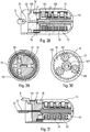
- the autoinjector comprises a central body 1, a control ring 2, a tapping spring 3, a control sleeve 4, a piston rod 5, a support pad 6, three locking elements 7, here in the form of balls, an injection spring 8, a control slide 9, a lower body 10, an actuator sleeve 11, a spring 12 of the actuator sleeve, a reservoir housing 13, a cover 14, an upper body 15, a plurality of planets 16, a plurality of satellites 17, a retarding spring 18, a trigger 19, a locking finger 20, a wire 21, an external shell 22 and a locking ring 23. All of these elements form part of the embodiment described, but not all of them are essential to the operation of the autoinjector, as will be more precisely described below.
- the cover 14 makes it possible in particular to lock the autoinjector during transport and storage. As long as this cover is assembled on the lower body 10, it prevents any actuation of the actuator sleeve 11, and therefore any triggering of the autoinjector.
- a tank A can be inserted into said autoinjector.
- This reservoir contains fluid, and includes a piston and a needle.
- the piston is adapted to move in said reservoir to inject the fluid product through said needle.
- a syringe A which can be of any type. More generally, it is understood that the term “syringe” in the present description encompasses any type of reservoir associated with a needle.
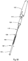
- syringe A is a pre-filled syringe. It advantageously comprises a needle cap B which protects and isolates the needle before using the autoinjector.
- this needle cap B is automatically removed when the cover 14 is removed from the lower body 10.
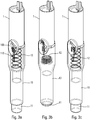
- FIGS. 2a to 2f illustrate the sequences of the use of the autoinjector of the figure 1 .
- the user wants to use the autoinjector, he takes the device, for example at the level of the external shell 22 and he presses the actuator sleeve 11, which in a first projected position projects out of the lower body 10, against the part of the body where he wants to inject.
- the actuator sleeve 11 On the figure 2b , we see that the pressure exerted by the user on the actuator sleeve 11 causes it to slide towards the inside of the body lower 10, with the effect of compressing the spring of the actuator sleeve 12.
- the actuator sleeve 11 When the actuator sleeve 11 reaches its actuation position, which is its end position inside the lower body 10, it triggers the stitching lock and therefore the movement of the control sleeve 4 in the lower body 10 under the effect of the stitching spring 3, with the consequence of a displacement of the syringe A in the lower body 10 and therefore the insertion of the needle of the syringe in the body of the user, as visible on the figure 2c .
- the autoinjector provides for a retraction of the syringe A.
- the needle is therefore retracted out of the body of the user towards the inside the autoinjector, as shown in the figure 2e .
- the actuator sleeve 11 is again moved out of the lower body 10 to a second projected position, under the effect of the spring 12 of the actuator sleeve, with a locking of said actuator sleeve 11, which guarantees absolute safety for the user and avoids any risk of injury to the needle after using the device.
- first and second projected positions of the actuator sleeve which, in the example shown, are different positions, could possibly be identical.
- Said actuator sleeve 11 has a flexible tab 110 which has double flexibility. On the one hand, it is radially flexible, that is to say it deforms towards the inside of the actuator sleeve 11. It is then also laterally flexible, that is to say it deforms in the peripheral direction of the actuator sleeve 11.
- An actuator sleeve 11 provided with such a flexible tab is simple to mold, which is favorable from the point of view of manufacturing costs.
- the flexible tab 110 advantageously comprises a part of rod 111 which is flexible and which ends in a head part 112.
- Said flexible tab 110 is adapted to deform on the one hand radially and on the other hand laterally with respect to said central body 1 when said actuator sleeve 11 is moved from its first projected position to its actuating position and then from its actuating position back to its second projected position.
- said flexible tab 110 is deformed radially when said actuator sleeve 11 moves from its first projected position, before actuation, to its actuation position, and said flexible tab is deformed laterally when said actuator sleeve 11 moves from its position actuation to its second projected position, at the end of use. It is this variant which is shown in the figures.
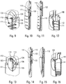
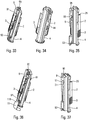
- FIGS. 3a, 3b and 3c are three partial schematic perspective views which show the end positions of the actuator sleeve 11, namely on the figure 3a the first position projected at rest before actuation, on the figure 3b the actuation position in which the actuator sleeve 11 has been inserted as far as possible inside the lower body 10, and on the figure 3c the second position projected with the actuator sleeve 11 locked relative to the lower body 10, at the end of use.
- the central body 1 has cutouts forming grooves and shoulders which are detailed below.
- the central body 1 is fixed to the lower body 10 and the actuator sleeve 11 is slidably disposed inside said lower body 10.
- the central body 1 comprises a first groove 101, substantially axial, and an opening 103, separated from said first groove 101 but arranged in the axial extension of said first groove 101.
- Said central body 1 also comprising a radial cam 102 disposed between said first groove 101 and said opening 103.
- said radial cam 102 can be formed by an inclined radial thickening of the wall of the central body 1, said thickening being formed at the axial end of the first groove 101.
- Said radial cam 102 cooperating with said head 112 of said flexible tab 110 to radially deform said flexible tab 110 and thus allow said head 112 to pass from said first groove 10 to said opening 103 during movement of the actuator sleeve 11 towards its actuating position.
- Said central body 1 comprises a final receiving zone 105 offset axially and laterally with respect to said opening 103. As visible in the figures, this final receiving zone 105 is disposed axially approximately at the level of said first groove 101.
- the opening 103 is connected to said final receiving zone 105 by a laterally inclined groove 104.
- An axial shoulder 106 is provided between said final receiving zone 105 and said inclined groove 104.
- said actuating sleeve 11 When said actuating sleeve 11 reaches its second projected position, after use, said head 112 comes to snap under said axial shoulder 106, thereby locking said actuator sleeve 11 relative to said central body 1 and relative to the lower body 10. From this locked position, said actuating sleeve can no longer be moved in the direction of its actuating position, due to the stop formed between the head 112 of the flexible tab 110 and the axial shoulder 106.
- the figures 4 to 8 represent the starting position, i.e. when the user will start using the autoinjector.
- the head 112 is disposed in said axial groove 101 of the central body 1.
- said head 112 of the flexible tab 110 will slide inside of said groove 101 of the central body.
- said radial cam 102 will cooperate with said head 112. This radial cam 102 will therefore deform the flexible tab 110, and in particular its stem portion 111, radially inward towards its longitudinal central axis.
- FIGS 9 to 12 illustrate the position in which the flexible tab 110 is radially deformed. As visible especially on the figure 11 , after this radial deformation, the head 112 of the flexible tab 110 will continue to move axially over an additional distance until it reaches said opening 103. The actuator sleeve 11 then reaches its actuation position, as shown in the figure 13 .
- the flexible tab 110 resiliently returns to its radially undeformed position.
- the head 112 of the flexible tab 110 then enters the interior of said opening 103 as visible on the figure 14 .
- the actuator sleeve 11 When the actuator sleeve 11 reaches its actuation position, that is to say in the position of the figures 13 to 16 , the spring 12 of the actuator sleeve has been compressed and the stitching lock is triggered by said actuator sleeve 11, as will be described more fully below, which causes the syringe A to move inside the lower body 10 and therefore stitching the needle into the body of the user.
- the actuating sleeve 11 does not move relative to the lower body 10, since the user maintains his pressure on the part of the body in which he injects.
- the spring 12 of the actuator sleeve 11 will urge said actuator sleeve 11 back from its actuation position to its second projected position, as shown on the figure 3c .
- the head 112 of the flexible tab 110 will cooperate with the inclined groove 104 as visible on the Figures 17 and 18 . This will cause an elastic deformation of the flexible tab 110, and in particular of its rod portion 111, as the actuator sleeve 11 will slide axially, the head 112 sliding in said inclined groove 104 laterally deforming said flexible tab 110 as clearly visible on the figure 17 .
- This inclined groove 104 ends in a final reception zone 105 provided with an axial shoulder 106.
- the head 112 of the flexible tab 110 will enter this final reception zone 105 and the upper edge 114 of the head 112 will cooperate with the axial shoulder 106, which will block the actuator sleeve 11 relative to the lower body 10.
- the actuator sleeve 11 can then no longer slide axially inwards from the lower body 10, and the safety device is then in the locked final position.
- the needle is completely protected after use and the user can no longer use the autoinjector or injure himself with the needle.
- the shapes of the grooves, their dimensions and their inclinations can be modified according to the needs and desired characteristics for the needle safety device.
- the actuator sleeve described above is particularly efficient and reliable, while being robust and easy and therefore inexpensive to mold.
- the Figures 32 to 46 more particularly describe the device for moving the syringe in the lower body 10. This device displacement ensures on the one hand the stitching, that is to say the insertion of the needle into the body of the user, and on the other hand the retraction of the needle after injection.
- the syringe A is moved axially in said lower body 10 in order to insert the needle into the body of the user.
- the syringe A is again moved in the other direction inside the lower body 10, to be retracted and thus automatically bring the needle out of the body of the user. In this way when the user withdraws the autoinjector from his body, the needle is no longer projecting but on the contrary retracted inside said autoinjector.
- a control ring 2 which cooperates with the control sleeve 4, with the control slide 9 as well as with the actuator sleeve 11. Furthermore, the trigger 19 intervenes to effect the retraction of the syringe inside the body as will be explained below.
- the figures 33 to 35 show the starting position before the syringe is moved for tapping. It can be seen that the control ring 2 is rotated by the stitching spring 3, which here is a spring acting in torsion. Such a torsion spring allows a painless stitching.
- the control ring 2 has three inclined profiles 24, 25, 26 similar to ramps, the functions of which will be explained below.
- the control ring 2 has a first inclined internal profile 24, such as a ramp, which will cooperate with a projection 44 of the control sleeve 4. Thus, the rotation of the ring 2 will gradually move said control sleeve 4 axially.
- This control sleeve 4 cooperates with the syringe housing 13 which receives the syringe, and thus a displacement of the control sleeve moves the syringe A in the lower body 10 to carry out the needle pricking.
- the figure 39 illustrates the position in which the needle is fully inserted, with the first inclined profile 24 which cooperates with the projection 44 of the control sleeve 4.
- the projection 91 of the control slide is also in contact with an external inclined profile 25 of the ring 2, such as an external ramp, which will cause an additional axial displacement of said control slide 9 relative to the actuator sleeve 11. This will move the control slide 9 in the same direction as the actuator sleeve 11 during stitching.
- the projection 92 of the control slide 9 comes close to an upper projection 119 of the actuator sleeve 11
- the projection 95 of the control slide 9 comes close to a projection 191 of the trigger 19, as visible on the figure 44 .
- the first internal inclined ramp 24 which cooperates with the projection 44 of the control sleeve 4 advantageously comprises a flat 241, that is to say a non-inclined portion, visible on the figure 41 .
- This dish 241 has a very important function since it guarantees that the start of the injection will only occur after the complete end of needle insertion into the body of the user. While for many autoinjectors it is necessary to start the injection a little before the needle reaches its final point of insertion, for reasons of manufacturing tolerance, the dish 241 on the ramp 24 makes it possible to avoid this phenomenon.
- the ring 2 has already completely moved the control sleeve 4 axially and therefore has achieved the complete insertion of the needle of the syringe into the body of the user, it is necessary that the ring 2 still turns on the circular arc formed by said plate, for example over approximately 30 °, to trigger the injection lock.
- the locking ring 23 of the injection lock is moved out of its locking position only after the additional rotation of the ring 2 on the arc formed by said plate 241.
- a second internal inclined profile 26, such as a ramp, of the control ring 2 will cooperate with a projection 235 of the locking ring 23 of the injection lock and move it out of its blocked position to release the injection, when the control ring 2 comes to the end of its additional rotation.
- the control ring 2 has three second internal inclined profiles 26 arranged at 120 ° from one another, and the locking ring 23 has three projections 235 also arranged at 120 ° from each other, a respective projection 235 cooperating with a second respective internal inclined profile 26.
- the piston rod 5 will release the rotation of a trigger 19, possibly with a certain delay if a delay device is used. From the moment the trigger 19 has made a predefined rotation, a projection 191 of the trigger 19 will cooperate with the upper shoulder 95 of the control slide 9, and this control slide 9 will be moved axially down on the figure 44 , which will release the rotation of the control ring 2 as described above.
- the figures 45 and 46 illustrate the retraction of the needle with the rotation of the ring 2 which will bring the projection 44 of the control sleeve facing an internal groove of the ring 2, which will cause, under the effect of the spring, the axial displacement in return of the control sleeve 4 inside the control ring 2 and therefore the retraction of the syringe and the needle.
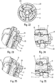
- the Figures 19 to 26 schematically illustrate an advantageous injection lock.
- the autoinjector comprises injection means, comprising in particular the piston rod 5, the injection spring 8 and the locking ring 23, these injection means being locked in a position loaded by said injection lock.
- the unlocking of said injection lock then causes actuation of said injection means and therefore the injection of the fluid product through the needle.
- said injection lock comprises a control sleeve 4 disposed in said central body 1, said control sleeve 4 containing said piston rod 5 and said injection spring 8, said piston rod 5 comprising a radial recess 50 receiving at at least one locking element 7 movable between a locking position and an unlocking position.
- Said at least one locking element 7 is preferably of substantially spherical shape.
- Said balls 7 are urged radially outwards by said piston rod 5 and are retained in the locking position by a locking member, which in this embodiment is formed by a locking ring 23.
- This locking ring 23 is axially movable relative to said piston rod 5 between a locking position, in which it maintains the locking elements 1007 in the locking position, and an unlocking position, in which said locking elements 1007 are released so as to unlock said lock injection, allowing said injection spring to move said piston rod 5 to its injection position.
- the figure 20 shows the injection lock in the locked position.
- the injection spring 8 cooperates on the one hand with the piston rod 5 and on the other hand with a support pad 6.
- This support pad 6 is formed by a ring disposed around said piston rod 5.
- the piston rod 5 comprises a peripheral recess 50, advantageously provided with an inclined surface 51, formed by a narrowing of the diameter of said piston rod 5.
- This piston rod 5 is disposed inside the control body 4 and is capable of be moved axially to the left on the figure 20 to push the plunger of syringe A inside the syringe and distribute the fluid contained in said syringe through the needle.
- the balls 7 are arranged in said recess 50 formed in the piston rod 5 and therefore cooperates with on the one hand the inclined wall 51 of the piston rod 5 and on the other hand with the upper surface 61 of said support pad 6 .
- the inclined surface 51 of the piston rod is in contact with the balls 7 so that under the effect of the compressed spring 8, said inclined surface 51 exerts a reaction force F1 on the balls 7, this force F1 not being exactly axial but directed slightly outward, thereby urging the balls 7 radially outward from the blocking position of the figure 20 .
- the locking ring 23 is provided radially outside the balls 7 for radially locking said balls in the locking position.
- the balls can be placed in housings of the control sleeve 4, the locking ring 23 comprising projections 231, one for each ball 7, which are positioned in contact with the balls 7 to prevent them from being moved radially outward.
- the pad 6 transmits the force F3 of the spring 8 to the balls 7, and the locking ring 23 exerts a reaction force F2 on the balls 7 to prevent a radial displacement of the latter.
- the balls 7 which support all the forces exerted on the lock in the locking position, with a three-point balance under the effect of the forces F1, F2 and F3.
- Such a lock is particularly stable and robust, and in particular makes it possible to resist drops tests. These tests simulate dropping the autoinjector on the ground after removing the cover 14, the objective being to avoid triggering of the injection lock during this fall. In particular, no force is exerted on the structural parts of the autoinjector, such as the central body 1 or the lower body 10. This lock thus makes it possible to avoid a risk of inadvertent disassembly of the device during transport or handling.
- the balls 7 could be replaced by non-spherical elements but of more complex rounded shape, by example in the shape of a cylinder or a bean, in order to further improve the stability of the lock.
- these non-spherical mobile elements could be made of metal, for example by cutting with steel wire.
- the locking ring 23 is moved according to arrow E1 on the figure 21 . This has the effect of releasing the balls 7 from their blocking position, the latter then being displaced radially outwards according to arrow E2.
- the locking ring 23 could also be rotated to a position where it releases the balls.
- the support pad 6 then abuts against an internal edge of the control sleeve 4 as shown by the arrow E3 on the figure 21 .
- the piston rod 5 is no longer retained by the balls 7 and is therefore moved axially, that is to say to the left on the figure 21 , to inject the product.
- the balls 7 can no longer return to the blocking position, prevented by the disc 6, as visible on the figure 21 .
- the figures 23 to 26 illustrate with slightly different views the two locking and unlocking positions of the injection lock as described above with reference to figures 20 and 21 .
- the injection lock shown on the Figures 19 to 26 enables a large force exerted by a compressed spring, in this case the injection spring 8, to be unlocked, by exerting a relatively low and easily controllable force on the locking ring 23.
- the force necessary to move said ring blocking 23 in the unlocking position may represent only 10%, or even only 5%, of the force exerted by the injection spring 8. This represents a very high efficiency which guarantees easy and reliable actuation of the device.
- a trigger 19 is actuated to retract the syringe and therefore the needle.
- a locking finger 20 extends through the trigger 19 and into the central channel 151 of the upper body 15.
- This rotation is blocked by the locking finger 20, advantageously oblong, which is adapted to rotate together with said trigger 19, but which is blocked in rotation by said central channel 151 of the upper body 15.
- the piston rod 5 moves axially, i.e. to the left on the figure 28 . As it moves, it will pull on the wire 21 which will therefore extend outside the channel 151.
- the rotation of the trigger 19 is blocked.
- the trigger 19 includes an inclined external ramp 190 which may have a projection 191 on one side. When the trigger 19 has achieved a predefined rotation, typically about one revolution, this projection 191 will come to cooperate with the control slide 9, which will move it axially and thus trigger the retraction of the needle, as described above.
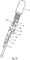
- the figures 27 to 31 illustrate an advantageous delay device.
- This delay device which is optional in an autoinjector, mainly aims to offset the retraction of the syringe A and therefore of the needle out of the body of the user after the end of the injection of the fluid product. inside said body. This allows in particular a diffusion for a few seconds of the product after its injection. Such a retarder also provides a benefit for the user, who no longer has to count, for example up to 10, after its injection, the time taken for this counting can be very variable from one user to another. With a self-timer, the sequence of use of an autoinjector is facilitated.
- the mechanical retarder shown on the figures 27 to 31 allows this retraction to be offset by a few seconds, this delay being predeterminable.
- the figure 27 illustrates a schematic exploded view of this delay device.
- This includes the upper body 15, several planets 16 with several satellites 17, the retarding spring 18, the trigger 19, the locking finger 20, the wire 21 and the piston rod 5. It is this piston rod 5 which will perform the actuation of the delay device when it reaches the end of the injection stroke with all of the product which has been injected.
- the figure 28 shows the delay device before actuation. It can be seen that the actuating rod 5 is connected to the locking finger 20 via the wire 21. In this position, the wire 21 and the locking finger 20 extend inside a central channel 151 of the upper body 15 and in the trigger 19.
- the upper body 15 has a gear 155 on its lateral internal surface, as clearly visible on the figure 30 . This internal gear 155 of the upper body 15 cooperates with a plurality of satellites 17 which are assembled on planets 16.
- the planets 16 comprise a disc-shaped plate on which are formed on one side satellite support rods 161 which each receive a satellite 17 in a rotary manner.
- the delay device uses the principle of planetary gears. Each stage of this device makes it possible to increase and / or slow down the rotations of the preceding stage.
- the trigger 19 cooperates with a first sun gear 16, the rods 161 of which extend inside said trigger 19.
- the gear 162 of this first sun gear 16 then cooperates with the satellites of a second adjacent sun gear, which cooperate with the lateral gear 155 of the upper body 15, thus increasing the rotation of the first sun gear and therefore of the trigger, and therefore braking this rotation.
- Each additional stage of the planetary gear train forming the retarder will further multiply these rotations, and therefore further slow down the rotation of the trigger 19.
- the rotation of the trigger 19 can be reduced to a single turn while the last sun gear 16 disposed at the very bottom of the upper body 15 will simultaneously carry out approximately fifty turns.
- Friction braking can also be provided, for example between the satellites 17 and the internal gear 155 of the upper body 15.
- the delay device therefore makes it possible to offset by a predetermined time the moment when said trigger will actuate the retraction of the needle, from the moment when the injection phase is finished.
- the principle of the deployable wire connected on the one hand to the piston rod 5 and on the other hand to the locking finger 20, can be used without the planetary gear system as shown in the figures 27 to 31 , as will be described in particular below with reference to the second embodiment.
- This very space-saving wire makes it possible to guarantee that the retraction of the needle does not begin until the injection phase is completely finished, in particular making it possible to compensate for any manufacturing tolerances.
- the use of a wire makes it possible to reduce the size of the device. Therefore, we can use it advantageously for different functions in an autoinjector, when there is a need to pull one piece relative to another.
- the outer shell 22 includes several indicators which make it possible to inform the user of the progress of the stitching, injection and retraction sequences. If a delay device is used, it is also possible to provide a display of said delay.
- the outer shell 22 may include several viewing windows, in this case three windows 221, 222, 223, which make it possible to view moving elements during the different actuation phases, these elements comprising indicators, typically colors.
- control slide 9 which at rest is in a first position relative to the central body 1, moves axially to a second position when the actuator sleeve is moved 11. It then remains in this second position throughout the entire phase d injection, and returns towards its first position during the retraction of the needle. It is only when the actuator sleeve returns to its second projected position, that the control slide reaches this first position.
- This control slide 9 may include one or more color indicators, for example a red horn area visible on the figure 1 . This slide can therefore be used to indicate on the one hand the projected position of the actuator sleeve 11 (first position) and on the other hand the stitching and injection phase (second position).
- the trigger 19, which triggers the retraction of the needle at the end of injection may also include an indicator, for example a red zone, which is displayed when said trigger has achieved its predefined rotation and thus actuated the retraction of the needle.
- the first display window 221 can be the end of injection window, that is to say that when a predefined color, for example red, appears in window 221, the injection is complete and the syringe has been retracted.
- the user therefore knows that when this first window of display is red, he can safely remove the autoinjector from his body.
- This indication can for example be provided by the trigger 19.
- the second viewing window 222 can be that of the tapping and injection phases, which turns red during the start of the tapping phase to the end of the injection phase. This prevents the user from removing the autoinjector from his body during these phases, which can last several seconds. This indication can be provided by the actuator slide 9.
- the third viewing window 223 can be that of the actuator sleeve 11, with the red displayed when the actuator sleeve 11 is in a position projected out of the lower body. This third viewing window 223 is therefore red before actuation, then again after use, when the actuator sleeve 11 is locked in the safety position.
- This indication can be provided by the control slide 9.
- the red zone of the actuator slide 9 passes from the third display window 223, before actuation ( figure 2a ) to the second viewing window 222 ( figure 2c ) when the actuator sleeve is in the actuation position where it triggers the stitching phase. During this transition, said red zone is not visible, being located between said windows 223 and 222 ( figure 2b ).
- control slide 9 During the stitching and injection phases, the control slide remains in its second position ( figure 2c & figure 2d ).
- the control slide 9 When the control slide 9 is again axially moved to its first position by the trigger 19, to actuate the retraction of the needle, the red zone goes back between the second window 222 to the third window 223, being again invisible ( figure 2e ), to finally reappear in the third window 223 when the actuator sleeve is locked in the second projected position ( figure 2f ).
- the combination of red in the first and third viewing windows 221 and 223 guarantees the end of the process of using the autoinjector, with the needle retracted and the actuator sleeve 11 locked, which guarantees optimum safety. .
- said external shell 22 may include any number of viewing windows, of any shape and size, and which could be positioned differently from the variant shown. in the figures.
- the same window can in particular display several different functions.
- Other variants are of course also possible.
- This outer shell 22 may also include one or more buttons for stitching and / or retraction of the needle, if the autoinjector provides such buttons for carrying out the stitching and / or retraction of the needle.
- the outer shell 22 could also include a temperature indicator for the product to be injected. Indeed, many products to inject are stored at 8 ° and it is often recommended to take them out 30-60 min in advance. If the product is too cold at the time of injection, this can cause pain in the patient.
- the shell 22 could include a display of the temperature of the reservoir containing the product to be injected. Alternatively, one could also provide a label which changes color with temperature. This temperature indicator could be provided on the hull, or on the reservoir, in particular the syringe, and be visible through a window of the hull.
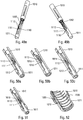
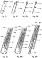
- the figures 47 to 74c illustrate several variants of a second embodiment of the invention.
- This second embodiment relates to a simplified autoinjector, consisting of fewer parts, and therefore simpler and less costly to manufacture and assemble. Some of these variants are not part of the invention but describe elements useful for the understanding of the invention. Only the variants shown on the figures 60 to 71 are part of the invention.
- the autoinjector comprises a lower body 1010, an actuator sleeve 1011, a spring 1012 of the actuator sleeve, a cover 1014, a control sleeve 1004, a piston rod 1005, a support pad 1006, three locking elements 1007, here in the form of balls, an injection spring 1008, a click member 1500, a wire 1021, and an external shell 1022.
- the cover 1014 makes it possible in particular to lock the autoinjector during transport and storage. As long as this cover is assembled on the lower body 1010, it prevents any actuation of the actuator sleeve 1011, and therefore any triggering of the autoinjector.
- syringe A is a pre-filled syringe. It advantageously comprises a needle cap B which protects and isolates the needle before using the autoinjector.
- this needle cap B is automatically removed when the cover 1014 is removed from the lower body 1010.
- this second embodiment has several elements similar to the first embodiment, these similar elements being designated by numerical references similar to those of the first embodiment, increased by 1000.
- the actuator sleeve referenced 11 in the first embodiment is now referenced 1011. Consequently, in the description of this second embodiment, it is mainly the differences compared to the first embodiment which will be described, it being understood that the other elements and functions remain similar if not identical between the two embodiments.
- the reservoir in this case the syringe A
- the reservoir in this case the syringe A
- the control sleeve 1004 is fixed relative to the lower body 1010, relative to the control sleeve 1004 and relative to the outer shell 1022.
- the actuator sleeve slides relative to the rest of the autoinjector.
- the figures 48a to 48e illustrate the sequences of the use of the autoinjector of the figure 47 .
- the user wants to use the autoinjector, he takes the device, for example at the level of the external shell 1022 and he presses the actuator sleeve 1011, which in a first projected position projects out of the lower body 1010, against the part of the body where he wants to inject.
- the actuator sleeve 1011 causes it to slide towards the inside of the lower body 1010, which discovers the needle and therefore its stitching due to the pressure exerted by the user on the autoinjector.
- the actuator sleeve 1011 When the actuator sleeve 1011 reaches its actuation position, which is its end position inside the lower body 1010, it triggers the injection phase, which is shown in the figures 48c and 48d . It can be seen that the piston rod 1005 slides inside the syringe A by pushing the piston of the latter under the effect of the injection spring 1008. The product is therefore dispensed.
- the actuator sleeve 1011 is again moved out of the lower body 1010 to a second projected position, under the effect of the spring of the actuator sleeve , with a locking of said actuator sleeve 1011, which guarantees absolute safety for the user and avoids any risk of injury to the needle after use of the device.
- the first and second projected positions of the actuator sleeve which, in the example shown, are different positions, could possibly be identical.
- said actuator sleeve 1011 also comprises a flexible tab 1110 which is only flexible laterally, that is to say that it deforms only in the peripheral direction of the actuator sleeve 1011.
- An actuator sleeve 1011 provided with a such flexible tab is even simpler to mold than the flexible double-flexible tab of the first embodiment, which is favorable from the point of view of manufacturing costs. With a flexible tab only laterally, it also gains in radial dimensions, which in particular makes it possible to improve the aesthetics of the autoinjector.
- the flexible tab 1110 advantageously comprises a rod part 1111 which is flexible and which ends in a head part 1112.
- said flexible tab 1110 is adapted to deform laterally with respect to said lower body 1010 on the one hand when said actuator sleeve 1011 is moved from its first projected position to its actuation position and on the other hand when said actuator sleeve 1011 is moved from its actuation position back to its second projected position.
- the head 1112 of the flexible tab must overcome a resistance to deform laterally at the start of actuation, to create a kind of precompression which guarantees that when the actuator sleeve will slide towards the inside of the lower body 1010, the needle will always penetrate the injection site to its desired injection position.
- this resistance is formed by a shoulder 1019 of the lower body 1010.
- said flexible tab 1110 is not deformed when said actuator sleeve 1011 moves from its first projected position, before actuation, to its actuation position, and said flexible tab is deformed laterally only when said actuator sleeve 1011 moves from its actuation position towards its second projected position, at the end of use.
- the actuator sleeve 1011 before actuation, is connected to said lower body 1010 by at least one breakable bridge 1500.
- This embodiment in particular allows easy molding, and therefore reduced manufacturing costs, adaptation and management of the 'breaking force of breakable bridges facilitated by the dimensioning of these bridges, and a function of witness of use.
- the figure 52 illustrates two breakable bridges 1500, adapted to break and therefore allow the actuator sleeve 1011 to slide relative to the lower body 1010 when the user presses the autoinjector on the injection site with a predetermined pressure.
- the operation of the flexible tab 1110 can be identical to that described in the context of the first embodiment, with an inclined groove, a final reception area and an axial shoulder cooperating with the head of the flexible tab to block it in the second projected position.
- the lower body 1010 may include a shoulder 1019 which is extended axially inward by a ramp 1018, for example formed by a rib, which is at least partially inclined.
- a ramp 1018 for example formed by a rib, which is at least partially inclined.
- this same projection 1019 can cooperate with the head 1112 of the flexible tab 1110 both at the start of actuation to create the precompression and at the end of actuation to block the actuator sleeve in the second projected position.
- the flexible tab 1110 can be fixed to said actuator sleeve 1011 only at the level of its rod portion 1111, with in this case the head 1112 forming a free end of said flexible tab.
- the flexible tab could also be fixed to said actuator sleeve on both sides, with the head 1112 disposed between the two fixing points. This implementation notably reinforces the robustness of the tab flexible. This variant could also be adapted to the flexible tab of the first embodiment.
- the flexible tab 1110 of the actuator sleeve 1011 advantageously cooperates with an opening 103, an inclined groove 104, a final receiving zone 105 and an axial shoulder 106 of the body 1010 which are similar to these same elements described above with reference to figures 4 to 18 .
- the figures 72 to 74c illustrate another alternative embodiment of the actuator sleeve.
- the reference numbers will be similar to those above, but increased by 1000.
- the actuator sleeve will be referenced 2011.
- the functions of the actuator sleeve 2011 and of the body 2010 are reversed, the body 2010 comprising the flexible tab 2110, and the actuator sleeve 2011 comprising the profile which will cooperate with said flexible tab 2110.
- the operation remains however similar to that described above, with the flexible tab 2110 which will gradually slide in said profile, and in particular in an inclined groove 2104 which connects an opening 2103 to a final reception area 2105.
- the flexible tab 2110 will snap onto the shoulder 2106, as visible on the figure 74c .
- the flexible tab must advantageously overcome a resistance to deform at the start of actuation, to create a kind of precompression which guarantees that when the actuator sleeve 2011 will slide towards the inside of the lower body 2010, the needle will always penetrate the injection site to its desired injection position. In the example of figures 72 to 74C , this resistance is formed by a shoulder 2019 of the actuator sleeve 2011.
- the flexible tab 2110 can be formed as a single piece on the body 2010, or as a variant be formed on a separate part assembled on said body 2010, by example for reasons of simplification and / or molding.
- the figures 53a, b, 54a, b , 57a, b, c and 58a, b, c illustrate the adaptation to the second embodiment of the injection lock described in the first embodiment.
- the autoinjector includes injection means, comprising in particular the piston rod 1005 and the injection spring 1008, these injection means being locked in a position loaded by said injection lock.
- the unlocking of said injection lock then causes actuation of said injection means and therefore the injection of the fluid product through the needle.
- said injection lock comprises a control sleeve 1004 disposed in said outer shell 1022, said control sleeve 1004 containing said piston rod 1005, said injection spring 1008 and a support pad 1006.
- the injection spring 1008 cooperates on the one hand with the piston rod 1005 and on the other hand with said support pad 1006.
- This support pad 1006 is formed by a ring disposed around said piston rod 1005.
- Said rod piston 1005 comprising at least one radial recess 1050 receiving at least one locking element 1007 movable between a locking position and an unlocking position.
- blocking elements 1007 there are three blocking elements 1007, preferably of substantially spherical shape, in particular in the form of balls, but a different number of blocking elements and different rounded shapes of these blocking elements are conceivable.
- Said blocking elements 1007 are biased radially outward by said piston rod 1005 and are retained in the blocking position by a blocking member, which in this second embodiment is formed by said control sleeve 1004.
- This sleeve control 1004 is axially movable relative to said piston rod 1005 between a locking position, in which it maintains the locking elements 1007 in the locking position, and an unlocking position, in which said locking elements 1007 are released thus unlocking said injection lock, allowing said injection spring to move said piston rod 1005 to its injection position.
- the control sleeve 1004 has one or more windows 1400 which allow the passage of the locking elements 1007 when the control sleeve has been moved to its unlocked position, shown in particular on the figures 58 .
- the movement of the control sleeve 1004 from its locked position to its unlocked position is achieved by a projection 1411 of the actuator sleeve 1011, which will cooperate with a shoulder 1410 of the control sleeve 1004, so that the control sleeve 1004 is in the unlocked position when the actuator sleeve 1011 is in the actuating position.
- the autoinjector comprises an audible and / or tactile indication device 1500 for indicating by an audible sound or by a tactile indication to the user that the injection phase is finished.
- This device will be described below in relation to three variants of the second embodiment, but it could also be adapted to an autoinjector produced according to the first embodiment.
- this sound and / or tactile indication device 1500 comprises a central part 1501 provided with at least one lateral part 1502 connected to said central part 1501 by a foldable and / or breakable link 1503.
- a foldable and / or breakable link 1503. In the example shown on figures 55 to 59c , there are two side pieces 1502 each connected to the central piece by a breakable link.
- the central part 1501 is connected to said piston rod 1005 by said wire 1021, which is fixed on the one hand to said central part 1501 and on the other hand on said piston rod 1005.
- the wire 1021 is wound around the piston rod and the central part 1501 is disposed outside the sleeve 1004 when the control sleeve 1004 is moved to its unlocked position, shown in particular on the figure 58a , an upper edge of said control sleeve 1004 comes into contact with said side pieces 1502.
- the wire 1021 will progressively unwind until be stretched at the end of injection as shown in the figure 58b .
- This shock is audible and / or tactile for the user, who therefore receives information about the end of injection.
- the wire 1021 is no longer completely taut, as illustrated diagrammatically on the Figures 59a and 59b .
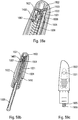
- the figures 60 to 64c illustrate a second variant of the audible and / or tactile indication device covered by the invention.
- the sound and / or tactile indication device 1500 comprises a movable element which is here formed by the control sleeve 1004, which comprises at its end distal with respect to the needle, one or more deformable legs 1510 which at the end of injection will abut against the outer shell 1022.
- This sleeve injection will abut against the outer shell 1022.
- This control sleeve 1004 is in a first position relative to the outer shell 1022 before actuation of the autoinjector, as shown in the figure 64a .
- a central part called a key 1120 here advantageously replaces the wire of the first previous variant.
- This 1120 key particularly visible on figures 63a and 63b , comprises a rod part 1121 which extends inside the piston rod 1005, this rod part being similar to the wire of the first variant.
- the key 1120 also includes a head portion 1122, disposed at the upper end (or distal relative to the needle) of said key. This head part cooperates with said deformable tabs 1510 of the control sleeve 1004, to prevent them from deforming radially inwards.
- these deformable legs 1510 block said control sleeve in its second position relative to said external shell 1022.
- the lower end (or proximal relative to the needle) of the rod part 1121 cooperates with the rod piston 1005 at the very end of injection, causing said key 1120 to slide relative to the control sleeve 1004 and to the external shell 1022.
- the head part 1122 no longer cooperates with the lugs 1510 of the sleeve which can then deform radially inwards.
- This has the effect of unlocking the control sleeve 1004, which is then moved to a third position against said external shell 1022 under the effect of the force exerted by the injection spring 1008. This creates an audible or otherwise detectable shock by the user, who then knows that the injection is finished.
- the outer shell 1022 comprises one or more, in particular three, viewing windows 1023 in which said deformable tabs 1510 become visible at the same time as they come to tap against the outer shell. This allows a visual indication simultaneously with the audible and / or tactile indication.
- said at least one viewing window 1023 is formed on or in the distal end edge of said external shell 1022, while being visible both in the axial direction and in the radial direction of said shell.
- This implementation avoids hiding the display window (s) 1023 when the autoinjector is taken in hand by the user, which guarantees good visualization of the information displayed in said at least one display window 1023 during the entire phase d from start to finish.
- several viewing windows 1023, in particular three, distributed around the distal end edge of the body 1022 a perfect viewing is guaranteed whatever the orientation of the autoinjector at the time of its use.
- control sleeve 1004 having three distinct positions: before injection when it is in the locking position, during injection when it is in the unlocking position, and after injection when it activated the audible and / or tactile indication device. This makes it possible to easily view these three distinct positions in an appropriate viewing window 1221.
- the external shell 1022 of this second embodiment could also also include several viewing windows as described in the first embodiment.
- the figures 65 to 71 illustrate a third alternative embodiment of the audible and / or tactile indication device also covered by the invention.
- the mobile element of the audible and / or tactile indication device is not formed by the control sleeve 1004 but by the support pad 1006 on which s supports the injection spring 1008.
- the figures 66a and 66b shows this support pad, which has one or more deformable legs 1520, which are similar to the deformable legs 1510 of the control sleeve 1004 of the second variant above.
- the operation is also similar, with the key 1120 which blocks by its head 1122 the deformation radial of said legs 1520, which blocks the support pad relative to the outer shell.
- a visual indication is also provided by one or more viewing windows 1023 of the external shell which show the deformable tabs 1520 of the support pad 1006.
- the figures 69 to 71 illustrate in more detail the operation of the audible and / or tactile indication device.
- the deformable tab 1520 is prevented from deforming radially inward by the presence of the head portion 1122 of the key 1120.
- the key was moved by the piston rod, and therefore, the deformable tab 1520 deformed radially inward. This caused the displacement of the support pad 1006 in the outer shell, with a shoulder 1521 of the deformable tab which abuts on a part of said outer shell, generating the sound and / or tactile indication, for example an audible sound. or a sensitive vibration.
- the end of the deformable tab 1520 is positioned in the window 1023 of the external shell 1022, as visible on the figure 70 .
- the figure 71 illustrates the end of the injection, with the piston rod 1005 which will pull on the rod part 1121 of the key 1120 to move it.
- the present invention applies to devices used in particular for the treatment of autoimmune diseases, for example of the rheumatoid arthritis type, multiple sclerosis, Crohn's disease, for cancer treatments, for antiviral treatments, for example of the type hepatitis, for diabetes treatments, for anemia treatments or for seizures, for example in case of anaphylactic shock.
- autoimmune diseases for example of the rheumatoid arthritis type, multiple sclerosis, Crohn's disease
- cancer treatments for antiviral treatments, for example of the type hepatitis, for diabetes treatments, for anemia treatments or for seizures, for example in case of anaphylactic shock.
- the actuator sleeve and / or the syringe displacement device for the stitching and / or retraction and / or the injection lock and / or the delay device and / or the audible and / or tactile indication device could be used independently of each other.
- the pricking of the needle and / or the retraction of the needle after injection could be controlled by one or more button (s).
- the audible and / or tactile indication device of the second embodiment could be used with an autoinjector of the type described in the first embodiment.
- Other modifications are also possible for a person skilled in the art without departing from the scope of the present invention as defined by the appended claims.
Landscapes
- Health & Medical Sciences (AREA)
- Engineering & Computer Science (AREA)
- Hematology (AREA)
- Anesthesiology (AREA)
- Biomedical Technology (AREA)
- Heart & Thoracic Surgery (AREA)
- Vascular Medicine (AREA)
- Life Sciences & Earth Sciences (AREA)
- Animal Behavior & Ethology (AREA)
- General Health & Medical Sciences (AREA)
- Public Health (AREA)
- Veterinary Medicine (AREA)
- Environmental & Geological Engineering (AREA)
- Infusion, Injection, And Reservoir Apparatuses (AREA)
Description
La présente invention concerne un autoinjecteur.The present invention relates to an autoinjector.
Les autoinjecteurs sont bien connus dans l'état de la technique. Ces dispositifs ont principalement pour but de réaliser une injection automatique du contenu d'une seringue à l'intérieur du corps d'un patient. Divers systèmes existent pour rendre automatique la pénétration de l'aiguille dans le corps du patient ainsi que l'injection du produit fluide contenu dans la seringue. Les autoinjecteurs sont des dispositifs relativement complexes qui doivent répondre à un certain nombre d'exigences de contraintes pour être fiables. La robustesse du dispositif, sa maniabilité, et sa facilité d'utilisation pour l'utilisateur sont également des éléments importants. Par ailleurs, la plupart de ces autoinjecteurs étant à usage unique, le coût de fabrication et d'assemblage est également un facteur dont il faut tenir compte.Autoinjectors are well known in the art. The main purpose of these devices is to automatically inject the contents of a syringe into the body of a patient. Various systems exist to make automatic the penetration of the needle into the patient's body as well as the injection of the fluid product contained in the syringe. Autoinjectors are relatively complex devices which must meet a certain number of constraint requirements to be reliable. The robustness of the device, its maneuverability, and its ease of use for the user are also important elements. In addition, most of these autoinjectors being disposable, the cost of manufacture and assembly is also a factor to be taken into account.
Il existe de nombreux autoinjecteurs sur le marché, qui présentent toutefois tous un certain nombre d'inconvénients.There are many autoinjectors on the market, all of which, however, have a number of drawbacks.
Ainsi, pour éviter un déclenchement intempestif de l'autoinjecteur, par exemple pendant un transport ou pendant le stockage, les dispositifs doivent comporter des moyens de verrouillage fiables. De même, lorsqu'un utilisateur souhaite utiliser l'autoinjecteur et qu'il déverrouille le dispositif, par exemple en retirant le capot, le dispositif ne doit pas se déclencher de manière intempestive mais seulement au moment où l'utilisateur le souhaite réellement, c'est-à-dire au moment où il l'applique contre la partie du corps dans laquelle il veut réaliser l'injection. Or, notamment quand les personnes utilisant l'autoinjecteur sont des personnes âgées ou handicapées, il peut arriver que l'utilisateur laisse tomber le dispositif au moment où il souhaite l'utiliser. Il est souhaitable que dans un tel cas l'autoinjecteur ne se déclenche pas tout seul. Il est donc important de prévoir une serrure de déclenchement fiable. D'un autre côté, il ne faut pas que l'utilisation de l'autoinjecteur devienne trop difficile, ce qui empêcherait des personnes faibles de l'utiliser. Il est donc difficile de trouver le bon compromis entre la sécurité du verrouillage et la facilité d'utilisation et d'actionnement de l'autoinjecteur. C'est un des objectifs de la présente invention de répondre à ce problème.Thus, to avoid inadvertent triggering of the autoinjector, for example during transport or during storage, the devices must include reliable locking means. Likewise, when a user wishes to use the autoinjector and unlocks the device, for example by removing the cover, the device should not be triggered inadvertently but only when the user actually wants it, c that is to say when he applies it against the part of the body in which he wants to perform the injection. However, especially when the people using the autoinjector are elderly or disabled, it may happen that the user drops the device when he wishes to use it. It is desirable that in such a case the autoinjector does not fire on its own. It is therefore important to provide a reliable trigger lock. On the other hand, the use of the autoinjector should not become too difficult, which would prevent weak people from using it. It is therefore difficult to find the right compromise between locking security and ease of use and actuation of the autoinjector. It is one of the objectives of the present invention to respond to this problem.
Par ailleurs, selon le volume du produit fluide distribué lors de l'injection et aussi en fonction de sa viscosité, le temps nécessaire pour réaliser cette injection peut être assez important, pouvant notamment dépasser plusieurs secondes. Il est alors très important que l'utilisateur ne retire pas le dispositif de son corps avant que l'injection soit complète. Il est donc souhaitable que le dispositif comporte des moyens permettant d'indiquer de manière fiable à l'utilisateur que l'injection est terminée.Furthermore, depending on the volume of the fluid distributed during the injection and also depending on its viscosity, the time required to carry out this injection can be quite significant, which can in particular exceed several seconds. It is therefore very important that the user does not remove the device from his body before the injection is complete. It is therefore desirable for the device to include means making it possible to indicate reliably to the user that the injection is complete.
Il est aussi important de garantir que le produit soit injecté à la bonne profondeur dans le corps, c'est-à-dire dans le bon tissu. La maitrise du début d'injection, pour garantir que celle-ci ne commencera que lorsque l'aiguille aura atteint sa position de piquage définitive, est donc aussi un aspect important.It is also important to ensure that the product is injected at the right depth in the body, that is, in the right tissue. Control of the start of injection, to guarantee that it will only start when the needle has reached its final stitching position, is therefore also an important aspect.
De plus, afin d'éviter tout risque de blessures après l'utilisation du dispositif, l'autoinjecteur doit comprendre un dispositif de sécurité aiguille qui évite que l'aiguille reste apparente après l'utilisation du dispositif. Ce dispositif de sécurité doit évidemment également être fiable et ne pas se libérer trop facilement. Il doit aussi être fonctionnel même si l'utilisateur actionne mal l'autoinjecteur, par exemple s'il le retire trop tôt de son corps, avant la fin de l'injection.In addition, in order to avoid any risk of injury after using the device, the autoinjector must include a needle safety device which prevents the needle from remaining visible after using the device. This safety device must obviously also be reliable and not be released too easily. It must also be functional even if the user actuates the autoinjector badly, for example if he withdraws it too early from his body, before the end of the injection.
Un autre aspect important avec les autoinjecteurs, notamment lorsque le volume de produit fluide est relativement important et/ou lorsque le produit fluide injecté est relativement visqueux, est de permettre au produit de diffuser du site d'injection pendant quelques secondes après ladite injection. Si l'utilisateur retire l'autoinjecteur immédiatement après la fin de l'injection, une partie du produit peut ressortir du corps de l'utilisateur ce qui diminue l'efficacité du traitement. Il est donc souhaitable de prévoir que l'utilisateur maintienne l'autoinjecteur contre son corps encore pendant quelques secondes après la fin de l'injection. Cet aspect est généralement résolu par les autoinjecteurs existants par la notice d'utilisation qui demande à l'utilisateur de compter dans sa tête un certain nombre de secondes avant de retirer le dispositif. Ceci n'est pas fiable et donc insatisfaisant, car le système dépend alors de l'utilisateur lui-même, qui dans certains cas peut être perturbé ou affaibli par l'action d'injection qu'il vient de réaliser.Another important aspect with autoinjectors, in particular when the volume of fluid product is relatively large and / or when the fluid product injected is relatively viscous, is to allow the product to diffuse from the injection site for a few seconds after said injection. If the user withdraws the autoinjector immediately after the end of the injection, part of the product may come out of the user's body, which reduces the effectiveness of the treatment. It is therefore desirable to provide that the user keeps the autoinjector against his body for a few seconds after the end of the injection. This aspect is generally solved by existing autoinjectors by the user manual which asks the user to count in his head a certain number of seconds before remove the device. This is not reliable and therefore unsatisfactory, because the system then depends on the user himself, who in certain cases can be disturbed or weakened by the injection action which he has just performed.
Les documents
La présente invention a pour but de fournir un autoinjecteur qui ne reproduit pas les inconvénients susmentionnés, et qui permet de répondre aux différentes exigences et contraintes importantes pour une utilisation sûre et fiable de l'autoinjecteur.The object of the present invention is to provide an autoinjector which does not reproduce the abovementioned drawbacks, and which makes it possible to meet the various important requirements and constraints for a safe and reliable use of the autoinjector.
La présente invention a aussi pour but de fournir un autoinjecteur qui soit fiable d'utilisation, qui permette de garantir la distribution de la totalité du produit fluide à l'endroit souhaité, qui permet à l'utilisateur de déterminer quand il doit retirer ou quand il peut retirer l'autoinjecteur de son corps après son utilisation, qui soit sûr et qui empêche tout risque de blessure, et qui soit simple et peut coûteux à fabriquer et à assembler.Another object of the present invention is to provide an autoinjector which is reliable in use, which makes it possible to guarantee the distribution of the entire fluid product at the desired location, which allows the user to determine when he must remove or when he can remove the autoinjector from his body after use, which is safe and which prevents any risk of injury, and which is simple and inexpensive to manufacture and assemble.
La présente invention a donc pour objet un autoinjecteur comportant une coque externe, un réservoir contenant du produit fluide et comportant un piston et une aiguille, tel qu'une seringue pré-remplie, ledit autoinjecteur comportant une tige de piston adaptée à coopérer avec le piston dudit réservoir, ladite tige de piston étant déplaçable entre une position chargée et une position d'injection dans laquelle ladite tige de piston a déplacé le piston du réservoir pour injecter le produit fluide à travers l'aiguille, un ressort d'injection étant prévu pour solliciter ladite tige de piston vers sa position d'injection, l'autoinjecteur comportant un élément mobile, contenant au moins partiellement ladite tige de piston et ledit ressort d'injection, ladite tige de piston étant déplaçable par rapport audit élément mobile lors de la phase d'injection, ledit autoinjecteur comportant un dispositif d'indication sonore et/ou tactile comportant une clé, ladite clé comportant une partie de tige qui s'étend à l'intérieur de la tige de piston, et une partie de tête, ledit élément mobile comportant au moins une patte déformable, ladite partie de tête de ladite clé coopérant avant injection avec ladite au moins une patte déformable pour empêcher toute déformation radiale de celle-ci, bloquant ledit élément mobile par rapport à ladite coque externe, ladite tige de piston, en fin d'injection, exerçant via ladite partie de tige de ladite clé une traction sur ladite partie de tête de ladite clé, provoquant le déplacement de ladite clé par rapport à ladite au moins une patte déformable, permettant ainsi une déformation radiale de ladite au moins une patte déformable et un déplacement axial dudit élément mobile sous l'effet dudit ressort d'injection, ledit déplacement générant une indication sonore et/ou tactile pour l'utilisateur.The present invention therefore relates to an autoinjector comprising an external shell, a reservoir containing fluid and comprising a piston and a needle, such as a pre-filled syringe, said autoinjector comprising a piston rod adapted to cooperate with the piston. of said reservoir, said piston rod being movable between a loaded position and an injection position in which said piston rod has moved the piston of the reservoir to inject the fluid product through the needle, an injection spring being provided for biasing said piston rod towards its injection position, the autoinjector comprising a mobile element, containing at least partially said piston rod and said injection spring, said piston rod being movable relative to said mobile element during the phase injection, said autoinjector comprising an audible indication device and / or touchscreen comprising a key, said key comprising a rod part which extends inside the piston rod, and a head part, said movable element comprising at least one deformable tab, said head part of said key cooperating before injection with said at least one deformable tab to prevent any radial deformation thereof, blocking said movable member relative to said outer shell, said piston rod, at the end of injection, exerting via said rod part of said key pulling on said head portion of said key, causing said key to move relative to said at least one deformable tab, thereby allowing a radial deformation of said at least one deformable tab and an axial displacement of said movable element under the effect of said injection spring, said displacement generating an audible and / or tactile indication for the user.
Avantageusement, ledit élément mobile est un manchon de commande comportant une ou plusieurs pattes déformables.Advantageously, said movable element is a control sleeve comprising one or more deformable tabs.
Avantageusement, ledit élément mobile est une pastille de support comportant une ou plusieurs pattes déformables.Advantageously, said movable element is a support pad comprising one or more deformable tabs.
Avantageusement, l'indication sonore et/ou tactile est générée par le contact entre ledit élément mobile et ladite coque externe.Advantageously, the audio and / or tactile indication is generated by the contact between said mobile element and said external shell.
Avantageusement, ladite coque externe comporte au moins une fenêtre fournissant une indication visuelle simultanément à l'indication sonore et/ou tactile.Advantageously, said external shell comprises at least one window providing a visual indication simultaneously with the sound and / or touch indication.
Avantageusement, ladite au moins une fenêtre est disposée sur le bord d'extrémité de ladite coque externe, ladite au moins une patte déformable étant visible dans ladite au moins une fenêtre après la fin de l'injection.Advantageously, said at least one window is arranged on the end edge of said outer shell, said at least one deformable tab being visible in said at least one window after the end of the injection.
La présente invention a également pour objet un autoinjecteur comportant une coque externe, un réservoir contenant du produit fluide et comportant un piston et une aiguille, tel qu'une seringue pré-remplie, ledit autoinjecteur comportant une tige de piston adaptée à coopérer avec le piston dudit réservoir, ladite tige de piston étant déplaçable entre une position chargée et une position d'injection dans laquelle ladite tige de piston a déplacé le piston du réservoir pour injecter le produit fluide à travers l'aiguille, un ressort d'injection étant prévu pour solliciter ladite tige de piston vers sa position d'injection, l'autoinjecteur comportant un manchon de commande, contenant ladite tige de piston et ledit ressort d'injection, ladite tige de piston étant déplaçable par rapport audit manchon de commande lors de la phase d'injection, caractérisé en ce que ledit autoinjecteur comporte un dispositif d'indication sonore et/ou tactile comportant une pièce centrale reliée à ladite tige de piston par un fil, ladite pièce centrale étant reliée à au moins une pièce latérale par une liaison pliable et/ou sécable, ladite tige de piston étant, en fin d'injection, adaptée à exercer via ledit fil une traction sur ladite pièce centrale, provoquant la déformation et/ou la casse de ladite au moins une liaison pliable et/ou sécable et ainsi la déformation et/ou le déplacement de ladite au moins une pièce latérale, permettant ainsi un déplacement axial dudit manchon de commande sous l'effet dudit ressort d'injection, ledit déplacement générant une indication sonore et/ou tactile pour l'utilisateur.The present invention also relates to an autoinjector comprising an external shell, a reservoir containing fluid and comprising a piston and a needle, such as a pre-filled syringe, said autoinjector comprising a piston rod adapted to cooperate with the piston. of said reservoir, said piston rod being movable between a loaded position and an injection position in which said piston rod moved the piston of the reservoir to inject the fluid through the needle, an injection spring being provided to urge said piston rod towards its injection position, the autoinjector comprising a control sleeve, containing said rod piston and said injection spring, said piston rod being movable relative to said control sleeve during the injection phase, characterized in that said autoinjector comprises an audible and / or tactile indication device comprising a central piece connected to said piston rod by a wire, said central part being connected to at least one lateral part by a foldable and / or breakable connection, said piston rod being, at the end of injection, adapted to exert traction on said wire said central part, causing deformation and / or breakage of said at least one foldable and / or breakable connection and thus deformation and / or displacement of said at least one lateral part, thus allowing i an axial displacement of said control sleeve under the effect of said injection spring, said displacement generating an audible and / or tactile indication for the user.
Avantageusement, ladite pièce centrale comporte deux pièces latérales reliée chacune à ladite pièce centrale par une liaison sécable.Advantageously, said central part comprises two lateral parts each connected to said central part by a breakable connection.
Avantageusement, ladite pièce centrale, avant injection, est disposée autour de ladite tige de piston, à l'extérieur dudit manchon de commande.Advantageously, said central part, before injection, is arranged around said piston rod, outside of said control sleeve.
Avantageusement, l'indication sonore et/ou tactile est générée par le contact entre ledit manchon de commande et ladite au moins une pièce latérale et/ou par le contact entre ladite au moins une pièce latérale et ladite coque externe.Advantageously, the audio and / or tactile indication is generated by the contact between said control sleeve and said at least one side piece and / or by the contact between said at least one side piece and said external shell.
Avantageusement, ladite pièce centrale est réalisée sous la forme d'un manchon cylindrique.Advantageously, said central part is produced in the form of a cylindrical sleeve.
Ces caractéristiques et avantages et d'autres de la présente invention apparaîtront plus clairement au cours de la description détaillée suivante, faite en référence aux dessins joints, donnés à titre d'exemples non limitatifs, et sur lesquels :
- La
figure 1 est une vue schématique en perspective éclatée des composants d'un autoinjecteur, selon un premier mode de réalisation avantageux, - Les
figures 2a à 2f sont des vues schématiques en section transversale illustrant les différentes séquences d'utilisation de l'autoinjecteur de lafigure 1 , - Les
figures 3a à 3c illustrent plus précisément trois stades différents d'un manchon actionneur avantageux, respectivement avant, en cours et après utilisation, - La
figure 4 est une vue de détail montrant le manchon actionneur dans la position de lafigure 3a , - Les
figures 5 et 6 sont des vues schématiques en section transversale selon deux plans de coupe différents montrant le manchon actionneur dans la position de lafigure 4 , - Les
figures 7 et 8 sont des vues schématiques en perspective partiellement découpées représentant le manchon actionneur dans la position desfigures 5 et 6 , - La
figure 9 est une vue similaire à celle de lafigure 4 , en début d'actionnement de l'autoinjecteur, pendant la phase de piquage, - Les
figures 10 à 11 sont des vues similaires auxfigures 5 et 6 , dans la position de lafigure 9 , - La
figure 12 est une vue similaire à celle de lafigure 8 , dans la position desfigures 10 et 11 , - La
figure 13 est une vue similaire à celle desfigures 4 et9 en cours d'actionnement, en phase d'injection, - Les
figures 14 et 15 sont des vues similaires à celles desfigures 10 et 11 représentant la position de lafigure 13 , - La
figure 16 est une vue similaire à celle de lafigure 12 , représentant la position desfigures 14 et 15 , - La
figure 17 est une vue similaire à celle de lafigure 13 , en fin d'actionnement, lorsque l'utilisateur retire l'autoinjecteur du site d'injection, - La
figure 18 est une vue similaire à celle de lafigure 17 , lorsque le manchon actionneur est verrouillé, - La
figure 19 est une vue schématique en perspective éclatée illustrant une serrure d'injection avantageuse, - La
figure 20 est une vue schématique en section transversale de la serrure d'injection de lafigure 19 , en position de blocage, - La
figure 21 est une vue similaire à celle de lafigure 20 , en position de déblocage, - La
figure 22 est une vue schématique de dessus en section horizontale de la serrure d'injection de lafigure 19 , en position de blocage, - La
figure 23 est une vue schématique en perspective partiellement découpée de la serrure d'injection de lafigure 19 , en position de blocage, - La
figure 24 est une vue schématique en section transversale de la serrure d'injection de lafigure 19 , en position de blocage, - La
figure 25 est une vue similaire à celle de lafigure 23 , en position de déblocage, - La
figure 26 est une vue similaire à celle de lafigure 24 en position de déblocage, - La
figure 27 est une vue schématique en perspective éclatée d'un dispositif retardateur avantageux, - La
figure 28 est une vue schématique en section transversale du dispositif retardateur de lafigure 27 avant son actionnement, - La
figure 29 est une vue schématique en section selon la ligne de coupe X de lafigure 28 , - La
figure 30 est une vue schématique en section selon la ligne de coupe Y de lafigure 28 , - La
figure 31 est une vue similaire à celle de lafigure 28 , en fin d'actionnement du dispositif retardateur, - La
figure 32 est une vue schématique en perspective éclatée d'un mécanisme de déplacement de seringue avantageux, - Les
figures 33 à 35 sont des vues schématique en perspective partiellement découpées du mécanisme de déplacement de lafigure 32 , avant actionnement, selon trois orientations différentes, - Les
figures 36 et 37 sont des vues similaires auxfigures 33 et 35 , en cours d'actionnement du mécanisme de déplacement, - Les
figures 38 à 41 sont des vues schématiques partielles en perspective partiellement découpées du mécanisme de déplacement de lafigure 32 , lorsque l'aiguille de la seringue a atteint sa position d'injection dans le corps de l'utilisateur, - Les
figures 42 et 43 sont des vues schématiques du mécanisme de déplacement de lafigure 32 en début de rétractation initiée par le retardateur, - La
figure 44 est une vue schématique du mécanisme de déplacement de lafigure 32 en début de rétractation initiée par le manchon actionneur, - Les
figures 45 et 46 sont des vues similaires auxfigures 43 , en fin d'injection,et 44 - La
figure 47 est une vue schématique en perspective éclatée des composants d'un autoinjecteur, selon un second mode de réalisation avantageux, - Les
figures 48a à 48e sont des vues schématiques en section transversale illustrant les différentes séquences d'utilisation de l'autoinjecteur de lafigure 47 , - Les
figures 49a et 49b sont des vues schématiques en perspective illustrant le corps inférieur et le manchon actionneur de l'autoinjecteur de lafigure 47 , - Les
figures 50a, 50b et 50c illustrent schématiquement la coopération entre le manchon actionneur et le corps inférieur de l'autoinjecteur de lafigure 47 , respectivement en position avant actionnement, après actionnement mais avant injection et après injection, - La
figure 51 est une vue similaire à celle de lafigure 50a , illustrant une variante de réalisation, - La
figure 52 est une vue de détail agrandie en perspective découpée, montrant une variante de manchon actionneur avec des ponts sécables, - Les
figures 53a et 53b illustrent des vues schématiques de l'autoinjecteur avant injection, - Les
figures 54a et 54b sont des vues similaires auxfigures 53a et 53b , après injection, - La
figure 55 est une vue schématique en perspective d'un dispositif d'indication sonore et/ou tactile selon une variante avantageuse, - La
figure 56 est une vue similaire à lafigure 55 , partiellement en section, - Les
figures 57a, 57b et 57c montrent l'autoinjecteur avant injection, - Les
figures 58a, 58b et 58c montrent l'autoinjecteur après injection mais avant actionnement du dispositif d'indication sonore et/ou tactile, - Les
figures 59a, 59b et 59c montrent l'autoinjecteur après injection et après actionnement du dispositif d'indication sonore et/ou tactile, - La
figure 60 est une vue schématique en perspective éclatée illustrant une variante de réalisation du dispositif d'indication sonore et/ou tactile, - Les
figures 61 et 62 sont des vues schématiques du manchon de commande du dispositif d'indication sonore et/ou tactile de lafigure 61 , - Les
figures 63a et 63b sont des vues schématiques de la clé du dispositif d'indication sonore et/ou tactile de lafigure 61 , - Les
figures 64a, 64b et 64c sont des vues schématiques de l'autoinjecteur de lafigure 60 , respectivement avant déverrouillage de la serrure d'injection, après déverrouillage de la serrure d'injection et en fin d'injection, illustrant le dispositif d'indication sonore et/ou tactile de lafigure 61 , - La
figure 65 montre une autre variante de réalisation du dispositif d'indication sonore et/ou tactile, - Les
figures 66a et 66b sont des vues schématiques de la pastille de support du dispositif d'indication sonore et/ou tactile de lafigure 65 , - Les
figures 67a et 67b sont des vues schématiques de la clé du dispositif d'indication sonore et/ou tactile de lafigure 65 , - Les
figures 68a, 68b et 68c sont des vues similaires auxfigures 64a, 64b et 64c , illustrant le dispositif d'indication sonore et/ou tactile de lafigure 65 , - Les
figures 69, 70 et 71 sont des vues de détail desfigures 68b et 68c , - La
figure 72 montre schématiquement une variante de réalisation du manchon actionneur, - La
figure 73 montre une autre vue de la variante de réalisation de lafigure 72 , et - Les
figures 74a, 74b et 74c sont des vues similaires auxfigures 50a, 50b et 50c , illustrant la variante de réalisation du manchon actionneur desfigures 71 et72 .
- The
figure 1 is a schematic exploded perspective view of the components of an autoinjector, according to a first advantageous embodiment, - The
Figures 2a to 2f are schematic cross-section views illustrating the different sequences of use of the autoinjector of thefigure 1 , - The
figures 3a to 3c more precisely illustrate three different stages of an advantageous actuator sleeve, respectively before, during and after use, - The
figure 4 is a detail view showing the actuator sleeve in the position of thefigure 3a , - The
Figures 5 and 6 are schematic cross-sectional views along two different cutting planes showing the actuator sleeve in the position of thefigure 4 , - The
Figures 7 and 8 are partially cut schematic perspective views showing the actuator sleeve in the position ofFigures 5 and 6 , - The
figure 9 is a view similar to that of thefigure 4 , at the start of actuation of the autoinjector, during the stitching phase, - The
figures 10 to 11 are views similar toFigures 5 and 6 , in the position of thefigure 9 , - The
figure 12 is a view similar to that of thefigure 8 , in the position offigures 10 and 11 , - The
figure 13 is a view similar to that offigures 4 and9 during activation, during the injection phase, - The
Figures 14 and 15 are views similar to those offigures 10 and 11 representing the position of thefigure 13 , - The
figure 16 is a view similar to that of thefigure 12 , representing the position ofFigures 14 and 15 , - The
figure 17 is a view similar to that of thefigure 13 , at the end of actuation, when the user removes the autoinjector from the injection site, - The
figure 18 is a view similar to that of thefigure 17 , when the actuator sleeve is locked, - The
figure 19 is a schematic exploded perspective view illustrating an advantageous injection lock, - The
figure 20 is a schematic cross-sectional view of the injection lock of thefigure 19 , in the locked position, - The
figure 21 is a view similar to that of thefigure 20 , in the unlocked position, - The
figure 22 is a schematic top view in horizontal section of the injection lock of thefigure 19 , in the locked position, - The
figure 23 is a schematic perspective view partially cut away of the injection lock of thefigure 19 , in the locked position, - The
figure 24 is a schematic cross-sectional view of the injection lock of thefigure 19 , in the locked position, - The
figure 25 is a view similar to that of thefigure 23 , in the unlocked position, - The
figure 26 is a view similar to that of thefigure 24 in the unlocked position, - The
figure 27 is a schematic exploded perspective view of an advantageous delay device, - The
figure 28 is a schematic cross-sectional view of the time delay devicefigure 27 before its activation, - The
figure 29 is a schematic view in section along the section line X of thefigure 28 , - The
figure 30 is a schematic view in section along the section line Y of thefigure 28 , - The
figure 31 is a view similar to that of thefigure 28 , at the end of actuation of the delay device, - The
figure 32 is a schematic exploded perspective view of an advantageous syringe displacement mechanism, - The
figures 33 to 35 are schematic perspective views partially cut away of the movement mechanism of thefigure 32 , before actuation, according to three different orientations, - The
figures 36 and 37 are views similar tofigures 33 and 35 , during actuation of the movement mechanism, - The
figures 38 to 41 are partial schematic perspective views partially cut away of the movement mechanism of thefigure 32 , when the syringe needle has reached its position of injection into the body of the user, - The
figures 42 and 43 are schematic views of the movement mechanism of thefigure 32 at the start of the withdrawal initiated by the self-timer, - The
figure 44 is a schematic view of the movement mechanism of thefigure 32 at the start of the retraction initiated by the actuator sleeve, - The
figures 45 and 46 are views similar tofigures 43 and 44 , at the end of injection, - The
figure 47 is a schematic exploded perspective view of the components of an autoinjector, according to a second advantageous embodiment, - The
figures 48a to 48e are schematic cross-section views illustrating the different sequences of use of the autoinjector of thefigure 47 , - The
figures 49a and 49b are schematic perspective views illustrating the lower body and the actuator sleeve of the autoinjector of thefigure 47 , - The
figures 50a, 50b and 50c schematically illustrate the cooperation between the actuator sleeve and the lower body of the autoinjector of thefigure 47 , respectively in position before actuation, after actuation but before injection and after injection, - The
figure 51 is a view similar to that of thefigure 50a , illustrating an alternative embodiment, - The
figure 52 is an enlarged detail view in cutaway perspective, showing a variant of actuator sleeve with breakable bridges, - The
figures 53a and 53b illustrate schematic views of the autoinjector before injection, - The
figures 54a and 54b are views similar tofigures 53a and 53b , after injection, - The
figure 55 is a schematic perspective view of an audible and / or tactile indication device according to an advantageous variant, - The
figure 56 is a view similar to thefigure 55 , partially in section, - The
figures 57a, 57b and 57c show the autoinjector before injection, - The
Figures 58a, 58b and 58c show the autoinjector after injection but before actuation of the audible and / or tactile indication device, - The
Figures 59a, 59b and 59c show the autoinjector after injection and after actuation of the audible and / or tactile indication device, - The
figure 60 is a schematic exploded perspective view illustrating an alternative embodiment of the sound and / or tactile indication device, - The
figures 61 and 62 are schematic views of the control sleeve of the audible and / or tactile indication device of thefigure 61 , - The
figures 63a and 63b are schematic views of the key of the audible and / or tactile indication device of thefigure 61 , - The
figures 64a, 64b and 64c are schematic views of the autoinjector of thefigure 60 , respectively before unlocking the injection lock, after unlocking the injection lock and at the end of injection, illustrating the audible and / or tactile indication device of thefigure 61 , - The
figure 65 shows another alternative embodiment of the audible and / or tactile indication device, - The
figures 66a and 66b are schematic views of the support pad of the audible and / or tactile indication device of thefigure 65 , - The
figures 67a and 67b are schematic views of the key of the audible and / or tactile indication device of thefigure 65 , - The
figures 68a, 68b and 68c are views similar tofigures 64a, 64b and 64c , illustrating the audible and / or tactile indication device of thefigure 65 , - The
figures 69, 70 and 71 are detail views offigures 68b and 68c , - The
figure 72 schematically shows an alternative embodiment of the actuator sleeve, - The
figure 73 shows another view of the alternative embodiment of thefigure 72 , and - The
figures 74a, 74b and 74c are views similar tofigures 50a, 50b and 50c , illustrating the alternative embodiment of the actuator sleeve of thefigures 71 and72 .
L'autoinjecteur va être décrit ci-après en référence à diverses variantes de deux modes de réalisation avantageux de celui-ci. Un premier mode de réalisation est représenté sur les
En se référant à la
Le capot 14 permet notamment de verrouiller l'autoinjecteur pendant le transport et le stockage. Tant que ce capot est assemblé sur le corps inférieur 10, il empêche tout actionnement du manchon actionneur 11, et donc tout déclenchement de l'autoinjecteur.The
Un réservoir A peut être insérée dans ledit autoinjecteur. Ce réservoir contient du produit fluide, et comporte un piston et une aiguille. Le piston est adapté à se déplacer dans ledit réservoir pour injecter le produit fluide à travers ladite aiguille. La présente description sera faite en référence à une seringue A, qui peut être de tout type. Plus généralement, il est entendu que le terme « seringue » dans la présente description englobe tout type de réservoir associé à une aiguille.A tank A can be inserted into said autoinjector. This reservoir contains fluid, and includes a piston and a needle. The piston is adapted to move in said reservoir to inject the fluid product through said needle. The present description will be made with reference to a syringe A, which can be of any type. More generally, it is understood that the term “syringe” in the present description encompasses any type of reservoir associated with a needle.
De préférence, la seringue A est une seringue pré-remplie. Elle comporte avantageusement un capuchon d'aiguille B qui protège et isole l'aiguille avant utilisation de l'autoinjecteur. Avantageusement, ce capuchon d'aiguille B est retiré automatiquement au moment du retrait du capot 14 à partir du corps inférieur 10.Preferably, syringe A is a pre-filled syringe. It advantageously comprises a needle cap B which protects and isolates the needle before using the autoinjector. Advantageously, this needle cap B is automatically removed when the
Les
Sur la
Lorsque l'utilisateur veut utiliser l'autoinjecteur, il prend le dispositif, par exemple au niveau de la coque externe 22 et il appuie le manchon actionneur 11, qui dans une première position projetée fait saillie hors du corps inférieur 10, contre la partie du corps où il veut réaliser l'injection. Sur la
Lorsque le manchon actionneur 11 atteint sa position d'actionnement, qui est sa position d'extrémité à l'intérieur du corps inférieur 10, il provoque le déclenchement de la serrure de piquage et donc le déplacement du manchon de commande 4 dans le corps inférieur 10 sous l'effet du ressort de piquage 3, avec comme conséquence un déplacement de la seringue A dans le corps inférieur 10 et donc l'insertion de l'aiguille de la seringue dans le corps de l'utilisateur, comme visible sur la
Lorsque l'aiguille atteint sa position d'injection avec une insertion complète de l'aiguille, la phase d'injection est déclenchée, ce qui est représenté sur les
A la fin de l'injection, et avec éventuellement un certain retard ou décalage temporel comme cela sera décrit ultérieurement, l'autoinjecteur prévoit une rétractation de la seringue A. L'aiguille est donc rétractée hors du corps de l'utilisateur vers l'intérieur de l'autoinjecteur, comme représenté sur la
En fin de rétractation, le manchon actionneur 11 est à nouveau déplacé hors du corps inférieur 10 vers une seconde position projetée, sous l'effet du ressort 12 du manchon actionneur, avec un verrouillage dudit manchon actionneur 11, ce qui garantit une sécurité absolue pour l'utilisateur et évite tout risque de blessures avec l'aiguille après utilisation du dispositif. Il est à noter que les première et seconde positions projetées du manchon actionneur, qui, dans l'exemple représenté, sont des positions différentes, pourraient éventuellement être identiques.At the end of retraction, the
Un manchon actionneur avantageux sera décrit ci-après plus en détail en référence aux
Ledit manchon actionneur 11 comporte une patte flexible 110 qui présente une double flexibilité. Elle est d'une part flexible radialement c'est-à-dire qu'elle se déforme vers l'intérieur du manchon actionneur 11. Elle est ensuite également flexible latéralement c'est-à-dire qu'elle se déforme dans la direction périphérique du manchon actionneur 11. Un manchon actionneur 11 pourvu d'une telle patte flexible est simple à mouler, ce qui est favorable du point de vue des coûts de fabrication. La patte flexible 110 comporte avantageusement une partie de tige 111 qui est flexible et qui se termine par une partie de tête 112. Ladite patte flexible 110 est adaptée à se déformer d'une part radialement et d'autre part latéralement par rapport audit corps central 1 lorsque ledit manchon actionneur 11 est déplacé de sa première position projetée vers sa position d'actionnement puis de sa position d'actionnement en retour vers sa seconde position projetée. De préférence, ladite patte flexible 110 est déformée radialement lorsque ledit manchon actionneur 11 se déplace de sa première position projetée, avant actionnement, vers sa position d'actionnement, et ladite patte flexible est déformée latéralement lorsque ledit manchon actionneur 11 se déplace de sa position d'actionnement vers sa seconde position projetée, en fin d'utilisation. C'est cette variante qui est représentée sur les figures.Said
Les
On constate que le corps central 1 comporte des découpes formant des rainures et des épaulements qui sont détaillés ci après. Le corps central 1 est fixé au corps inférieur 10 et le manchon actionneur 11 est disposé de manière coulissante à l'intérieur dudit corps inférieur 10.It can be seen that the
Le corps central 1 comporte une première rainure 101, sensiblement axiale, et une ouverture 103, séparée de ladite première rainure 101 mais disposée dans le prolongement axial de ladite première rainure 101. Ledit corps central 1 comportant également une came radiale 102 disposée entre ladite première rainure 101 et ladite ouverture 103. Comme visible notamment sur les
Ledit corps central 1 comporte une zone de réception finale 105 décalée axialement et latéralement par rapport à ladite ouverture 103. Comme visible sur les figures, cette zone de réception finale 105 est disposée axialement environ au niveau de ladite première rainure 101. L'ouverture 103 est reliée à ladite zone de réception finale 105 par une rainure inclinée latéralement 104. Un épaulement axial 106 est prévu entre ladite zone de réception finale 105 et ladite rainure inclinée 104. Ainsi, lorsque ledit manchon actionneur 11 revient de sa position d'actionnement vers sa seconde position projetée, ladite tête 112 de la patte flexible 110 coulisse dans ladite rainure inclinée latéralement 104, déformant ainsi latéralement ladite patte flexible 110. Lorsque ledit manchon actionneur 11 atteint sa seconde position projetée, après utilisation, ladite tête 112 vient s'encliqueter sous ledit épaulement axial 106, verrouillant ainsi ledit manchon actionneur 11 par rapport audit corps central 1 et par rapport au corps inférieur 10. A partir de cette position verrouillée, ledit manchon actionneur ne peut plus être déplacé en direction de sa position d'actionnement, de part la butée formée entre la tête 112 de la patte flexible 110 et l'épaulement axial 106.Said
Les
Les
Dans cette position d'actionnement, la patte flexible 110 revient élastiquement dans sa position non déformée radialement. La tête 112 de la patte flexible 110 rentre alors à l'intérieur de ladite ouverture 103 comme visible sur la
La déformation radiale de la patte flexible 110, nécessaire pour déplacer le manchon actionneur de sa première position projetée vers sa position d'actionnement, génère une certaine résistance. Combinée à la force de compression du ressort 12, cette résistance oblige l'utilisateur à exercer au moins une force prédéterminée pour réaliser le déplacement du manchon actionneur 11 à l'intérieur du corps inférieur 10. Ceci évite tout risque d'actionnement accidentel ou non souhaité après retrait du capot 14. L'actionnement n'a lieu que si l'utilisateur exerce ladite force prédéterminée sur le manchon actionneur 11. Ce seuil de force crée aussi une certaine précompression dans la main de l'utilisateur, avec pour effet que lorsque ce seuil est atteint, le déplacement du manchon actionneur 11 vers sa position d'actionnement est garanti.The radial deformation of the
Lorsque le manchon actionneur 11 atteint sa position d'actionnement, c'est-à-dire dans la position des
En fin d'utilisation, lorsque l'utilisateur va retirer l'autoinjecteur de son corps, le ressort 12 du manchon actionneur 11 va solliciter ledit manchon actionneur 11 en retour de sa position d'actionnement vers sa seconde position projetée, comme cela est représenté sur la
Bien entendu, les formes des rainures, leurs dimensions et leurs inclinaisons peuvent être modifiées en fonction des besoins et des caractéristiques souhaitées pour le dispositif de sécurité aiguille.Of course, the shapes of the grooves, their dimensions and their inclinations can be modified according to the needs and desired characteristics for the needle safety device.
Le manchon actionneur décrit ci-dessus est particulièrement efficace et fiable, tout en étant robuste et facile et donc peu coûteux à mouler.The actuator sleeve described above is particularly efficient and reliable, while being robust and easy and therefore inexpensive to mold.
Les
Comme nous l'avons vu précédemment, en début d'actionnement, la seringue A est déplacée axialement dans ledit corps inférieur 10 pour réaliser l'insertion de l'aiguille dans le corps de l'utilisateur. Après injection du produit fluide dans le corps de l'utilisateur, et éventuellement après un certain retard fourni par le dispositif retardateur décrit ci-dessus, la seringue A est à nouveau déplacée dans l'autre direction à l'intérieur du corps inférieur 10, pour être rétractée et ainsi faire automatiquement sortir l'aiguille du corps de l'utilisateur. De cette manière lorsque l'utilisateur retire l'autoinjecteur de son corps, l'aiguille n'est plus saillante mais au contraire rétractée à l'intérieur dudit autoinjecteur.As we have seen previously, at the start of actuation, the syringe A is moved axially in said
Pour réaliser ces déplacements en va-et-vient de la seringue A dans le corps inférieur 10, il est prévu une bague de commande 2 qui coopère avec le manchon de commande 4, avec le coulisseau de commande 9 ainsi qu'avec le manchon actionneur 11. Par ailleurs, le déclencheur 19 intervient pour réaliser la rétractation de la seringue à l'intérieur du corps comme cela sera expliqué ci-après.To make these back-and-forth movements of the syringe A in the
Les
Dans cette position initiale des
Lorsque le manchon actionneur 11 arrive dans sa position d'extrémité à l'intérieur du corps inférieur 10, comme représenté sur la
La bague de commande 2 comporte trois profils inclinés 24, 25, 26 similaires à des rampes, dont les fonctions seront explicitées ci-après.The
La bague de commande 2 comporte un premier profil interne incliné 24, telle qu'une rampe, qui va coopérer avec une projection 44 du manchon de commande 4. Ainsi, la rotation de la bague 2 va progressivement déplacer axialement ledit manchon de commande 4. Ce manchon de commande 4 coopère avec le logement de seringue 13 qui reçoit la seringue, et ainsi un déplacement du manchon de commande déplace la seringue A dans le corps inférieur 10 pour réaliser le piquage de l'aiguille.The
La
Pendant le déplacement du manchon de commande 4 et donc l'insertion de l'aiguille dans le corps de l'utilisateur, la projection 91 du coulisseau de commande est également en contact avec un profil incliné externe 25 de la bague 2, tel qu'une rampe externe, qui va provoquer un déplacement axial supplémentaire dudit coulisseau de commande 9 par rapport au manchon actionneur 11. Ceci va déplacer le coulisseau de commande 9 dans la même direction que le manchon actionneur 11 lors du piquage. De ce fait, la projection 92 du coulisseau de commande 9 vient proche d'une projection supérieure 119 du manchon actionneur 11, et la projection 95 du coulisseau de commande 9 vient proche d'une projection 191 du déclencheur 19, comme visible sur la
La première rampe inclinée interne 24 qui coopère avec la projection 44 du manchon de commande 4 comporte avantageusement un plat 241, c'est-à-dire une portion non inclinée, visible sur la
Lorsque l'injection est déclenchée par la bague de blocage 23, la rotation de la bague de commande 2 est à nouveau bloquée par le coulisseau de commande 9.When the injection is triggered by the locking
Avec le coulisseau de commande 9 dans la position de la
Dans un fonctionnement normal, l'injection se termine et comme cela sera décrit ci-après, la tige de piston 5 va libérer la rotation d'un déclencheur 19, éventuellement avec un certain retard si un dispositif retardateur est utilisé. A partir du moment où le déclencheur 19 a réalisé une rotation prédéfinie, une projection 191 du déclencheur 19 va coopérer avec l'épaulement supérieur 95 du coulisseau de commande 9, et ce coulisseau de commande 9 va être déplacé axialement vers le bas sur la
Les
Les
Comme représenté sur la
La
Comme visible sur la
La surface inclinée 51 de la tige de piston est au contact des billes 7 de sorte que sous l'effet du ressort comprimé 8, ladite surface inclinée 51 exerce une force de réaction F1 sur les billes 7, cette force F1 n'étant pas exactement axiale mais dirigée légèrement vers l'extérieur, sollicitant ainsi les billes 7 radialement vers l'extérieur de la position de blocage de la
La bague de blocage 23 est prévue radialement à l'extérieur des billes 7 pour bloquer radialement lesdites billes dans la position de blocage. En se référant plus particulièrement à la
La pastille 6 transmet la force F3 du ressort 8 aux billes 7, et la bague de blocage 23 exerce une force de réaction F2 sur les billes 7 pour empêcher un déplacement radial de celles-ci. Ainsi, ce sont les billes 7 qui supportent tous les efforts exercés sur la serrure dans la position de blocage, avec un équilibre en trois points sous l'effet des forces F1, F2 et F3. Une telle serrure est particulièrement stable et robuste, et permet notamment de résister aux drops tests. Ces tests simulent le fait de laisser tomber l'autoinjecteur par terre après avoir retirer le capot 14, l'objectif étant d'éviter un déclenchement de la serrure d'injection lors de cette chute. En particulier, aucune force n'est exercée sur les pièces de structure de l'autoinjecteur, tel que le corps central 1 ou le corps inférieur 10. Cette serrure permet ainsi d'éviter un risque de démontage intempestif du dispositif pendant un transport ou une manipulation.The
Il est à noter que les billes 7 pourraient être remplacées par des éléments non sphériques mais de forme arrondie plus complexe, par exemple en forme de cylindre ou de haricot, afin d'améliorer encore la stabilité de la serrure. Dans ce cas, ces éléments mobiles non sphériques pourraient être réalisés en métal, par exemple par découpe à fil d'acier.It should be noted that the
Lorsque l'aiguille de la seringue a complètement pénétré le corps de l'utilisateur, et seulement après cette insertion totale, comme cela sera décrit plus tard, la bague de blocage 23 est déplacée selon la flèche E1 sur la
Les
La serrure d'injection représentée sur les
Lorsque l'injection est terminée, c'est-à-dire lorsque la tige de piston 5 a atteint sa position d'extrémité dans laquelle le piston de la seringue A a été déplacé pour injecter le produit fluide, un déclencheur 19 est actionné pour rétracter la seringue et donc l'aiguille.When the injection is complete, that is to say when the
Lors de la phase d'injection, un doigt de verrouillage 20 s'étend à travers le déclencheur 19 et dans le canal central 151 du corps supérieur 15. Un ressort retardateur 18, ici un ressort à spirale, sollicite ledit déclencheur 19 en rotation. Cette rotation est bloquée par le doigt de verrouillage 20, avantageusement de forme oblongue, qui est adapté à tourner ensemble avec ledit déclencheur 19, mais qui est bloqué en rotation par ledit canal central 151 du corps supérieur 15. Pendant la phase d'injection, la tige de piston 5 se déplace axialement, c'est-à-dire vers la gauche sur la
Les
Ce dispositif retardateur, qui est optionnel dans un autoinjecteur, a principalement pour but de décaler dans le temps la rétractation de la seringue A et donc de l'aiguille hors du corps de l'utilisateur après la fin de l'injection du produit fluide à l'intérieur dudit corps. Ceci permet notamment une diffusion pendant quelques secondes du produit après son injection. Un tel retardateur procure aussi un bénéfice pour l'utilisateur, qui n'a plus à compter, par exemple jusqu'à 10, après son injection, le temps pris pour ce comptage pouvant être très variable d'un utilisateur à un autre. Avec un retardateur, on facilite la séquence d'utilisation d'un autoinjecteur.This delay device, which is optional in an autoinjector, mainly aims to offset the retraction of the syringe A and therefore of the needle out of the body of the user after the end of the injection of the fluid product. inside said body. This allows in particular a diffusion for a few seconds of the product after its injection. Such a retarder also provides a benefit for the user, who no longer has to count, for example up to 10, after its injection, the time taken for this counting can be very variable from one user to another. With a self-timer, the sequence of use of an autoinjector is facilitated.
Le retardateur mécanique représenté sur les
La
La
Lorsqu'un dispositif retardateur est utilisé, le déclencheur 19 coopère avec un premier planétaire 16, dont les tiges 161 s'étendent à l'intérieur dudit déclencheur 19. L'engrenage 162 de ce premier planétaire 16 coopère alors avec les satellites d'un second planétaire adjacent, qui coopèrent avec l'engrenage latéral 155 du corps supérieur 15, démultipliant ainsi la rotation du premier planétaire et donc du déclencheur, et donc freinant cette rotation. Chaque étage supplémentaire du train épicycloïdal formant le retardateur va davantage démultiplier ces rotations, et donc davantage freiner la rotation du déclencheur 19. Ainsi, avec quatre étages comme représenté sur les figures, on peut ramener à un seul tour la rotation du déclencheur 19 alors que le dernier planétaire 16 disposé tout au fond du corps supérieur 15 réalisera simultanément environ cinquante tours.When a delay device is used, the
Selon le nombre d'étages et/ou selon de nombre de satellites et/ou selon la forme des planétaires et/ou selon les dimensions des engrenages en jeu, on peut régler assez précisément le retard entre le moment où le dispositif retardateur est déclenché et le moment où le déclencheur 19 aura réalisé sa rotation prédéfinie pour déclencher la rétractation de la seringue, comme cela sera explique ultérieurement. Un freinage par frottements peut aussi être prévu, par exemple entre les satellites 17 et l'engrenage interne 155 du corps supérieur 15.Depending on the number of stages and / or according to the number of satellites and / or according to the shape of the planets and / or according to the dimensions of the gears in play, the delay between the moment when the delay device is triggered can be adjusted fairly precisely and the moment when the
Le dispositif retardateur permet donc de décaler d'un temps prédéterminé le moment où ledit déclencheur va actionner la rétractation de l'aiguille, à partir du moment où la phase d'injection est terminée.The delay device therefore makes it possible to offset by a predetermined time the moment when said trigger will actuate the retraction of the needle, from the moment when the injection phase is finished.
Il est à noter que le principe du fil déployable connecté d'une part à la tige de piston 5 et d'autre part au doigt de verrouillage 20, peut être utilisé sans le système de train épicycloïdal tel que représenté sur les
Selon un aspect avantageux, la coque externe 22 comporte plusieurs indicateurs qui permettent d'informer l'utilisateur de l'avancement des séquences de piquage, d'injection et de rétractation. En cas d'utilisation d'un dispositif retardateur, on peut aussi prévoir un affichage dudit retard.According to an advantageous aspect, the
Ainsi, comme visible sur les
Ainsi, le coulisseau de commande 9, qui au repos est dans une première position par rapport au corps central 1, se déplace axialement vers une seconde position lors du déplacement du manchon actionneur 11. Il reste ensuite dans cette seconde position pendant toute la phase d'injection, et revient en direction de sa première position lors de la rétractation de l'aiguille. Ce n'est que lorsque le manchon actionneur retourne à sa seconde position projetée, que le coulisseau de commande atteint cette première position. Ce coulisseau de commande 9 peut comporter un ou plusieurs indicateurs de couleur, par exemple une zone rouge corne visible sur la
Le déclencheur 19, qui déclenche la rétractation de l'aiguille en fin d'injection, peut aussi comporter un indicateur, par exemple une zone rouge, qui s'affiche lorsque ledit déclencheur a réalisé sa rotation prédéfinie et ainsi actionné la rétractation de l'aiguille.The
Ainsi, la première fenêtre de visualisation 221 peut être la fenêtre de fin d'injection, c'est-à-dire que lorsqu'une couleur prédéfinie, par exemple le rouge, apparaît dans la fenêtre 221, l'injection est terminée et la seringue a été rétractée. L'utilisateur sait donc que lorsque cette première fenêtre de visualisation est rouge, il peut retirer l'autoinjecteur en toute sécurité de son corps. Cette indication peut par exemple être fournie par le déclencheur 19.Thus, the first display window 221 can be the end of injection window, that is to say that when a predefined color, for example red, appears in window 221, the injection is complete and the syringe has been retracted. The user therefore knows that when this first window of display is red, he can safely remove the autoinjector from his body. This indication can for example be provided by the
La seconde fenêtre de visualisation 222 peut être celle des phases de piquage et d'injection, qui passe au rouge pendant du début de la phase de piquage à la fin de la phase d'injection. Ceci permet d'éviter que l'utilisateur ne retire l'autoinjecteur de son corps pendant ces phases, qui peuvent durer plusieurs secondes. Cette indication peut être fournie par le coulisseau actionneur 9.The second viewing window 222 can be that of the tapping and injection phases, which turns red during the start of the tapping phase to the end of the injection phase. This prevents the user from removing the autoinjector from his body during these phases, which can last several seconds. This indication can be provided by the
La troisième fenêtre de visualisation 223 peut être celle du manchon actionneur 11, avec le rouge affiché lorsque le manchon actionneur 11 est dans une position projetée hors du corps inférieur. Cette troisième fenêtre de visualisation 223 est donc rouge avant actionnement, puis à nouveau après utilisation, lorsque le manchon actionneur 11 est verrouillé en position de sécurité. Cette indication peut être fournie par le coulisseau de commande 9. Dans l'exemple représenté, la zone rouge du coulisseau actionneur 9 passe de la troisième fenêtre de visualisation 223, avant actionnement (
Dans cette configuration, la combinaison du rouge dans les première et troisième fenêtres de visualisation 221 et 223 garantit la fin du processus d'utilisation de l'autoinjecteur, avec l'aiguille rétractée et le manchon actionneur 11 verrouillé, ce qui garantit une sécurité optimale.In this configuration, the combination of red in the first and third viewing windows 221 and 223 guarantees the end of the process of using the autoinjector, with the needle retracted and the
Bien entendu, d'autres moyens d'affichage ou d'indication sont aussi possibles, et ladite coque externe 22 peut comporter un nombre quelconque de fenêtre de visualisation, de formes et de dimensions quelconques, et qui pourraient être positionnées différemment de la variante représentée sur les figures. Une même fenêtre peut notamment afficher plusieurs fonctions différentes.Of course, other display or indication means are also possible, and said
Eventuellement, dans la première fenêtre de visualisation 221 ou dans une autre fenêtre de visualisation, par exemple une fenêtre de visualisation supplémentaire, on peut prévoir d'afficher l'état du dispositif retardateur, par exemple avec un décompte. Celui-ci pourrait être réalisé par exemple avec des valeurs numériques inscrites sur le bord latéral externe du déclencheur qui passe progressivement dans une fenêtre de visualisation appropriée et qui affiche en seconde le décompte du retardateur. D'autres variantes sont bien entendu également possibles.Optionally, in the first viewing window 221 or in another viewing window, for example an additional viewing window, provision may be made to display the state of the delay device, for example with a countdown. This could be done, for example, with numerical values written on the external lateral edge of the trigger which progressively passes through an appropriate viewing window and which displays the countdown of the self-timer in seconds. Other variants are of course also possible.
Cette coque externe 22 peut aussi comporter un ou des boutons de piquage et/ou de rétractation de l'aiguille, si l'autoinjecteur prévoit de tels boutons pour réaliser le piquage et/ou la rétractation de l'aiguille.This
La coque externe 22 pourrait aussi comporter un indicateur de température du produit à injecter. En effet, beaucoup de produits à injecter sont stockés à 8° et il est souvent recommandé de les sortir 30-60 min a l'avance. Si le produit est trop froid au moment de l'injection, ceci peut provoquer des douleurs chez le patient. Par exemple, la coque 22 pourrait comporter un affichage de la température du réservoir contenant le produit à injecter. En variante, on pourrait aussi prévoir une étiquette qui change de couleur avec la température. Cet indicateur de température pourrait être prévu sur la coque, ou sur le réservoir, notamment la seringue, et être visible à travers une fenêtre de la coque.The
Les
Dans la variante de la
Le capot 1014 permet notamment de verrouiller l'autoinjecteur pendant le transport et le stockage. Tant que ce capot est assemblé sur le corps inférieur 1010, il empêche tout actionnement du manchon actionneur 1011, et donc tout déclenchement de l'autoinjecteur.The
Comme pour le premier mode de réalisation, la seringue A est une seringue pré-remplie. Elle comporte avantageusement un capuchon d'aiguille B qui protège et isole l'aiguille avant utilisation de l'autoinjecteur. Avantageusement, ce capuchon d'aiguille B est retiré automatiquement au moment du retrait du capot 1014 à partir du corps inférieur 1010.As for the first embodiment, syringe A is a pre-filled syringe. It advantageously comprises a needle cap B which protects and isolates the needle before using the autoinjector. Advantageously, this needle cap B is automatically removed when the
Il est à noter que ce second mode de réalisation présente plusieurs éléments similaires au premier mode de réalisation, ces éléments similaires étant désignés par des références numériques similaires à celles du premier mode de réalisation, augmentées de 1000. Ainsi, par exemple, le manchon actionneur référencé 11 dans le premier mode de réalisation est maintenant référencé 1011. Par conséquent, dans la description de ce second mode de réalisation, ce sont principalement les différences par rapport au premier mode de réalisation qui seront décrites, étant entendu que les autres éléments et fonctions demeurent similaires sinon identiques entre les deux modes de réalisation.It should be noted that this second embodiment has several elements similar to the first embodiment, these similar elements being designated by numerical references similar to those of the first embodiment, increased by 1000. Thus, for example, the actuator sleeve referenced 11 in the first embodiment is now referenced 1011. Consequently, in the description of this second embodiment, it is mainly the differences compared to the first embodiment which will be described, it being understood that the other elements and functions remain similar if not identical between the two embodiments.
La principale différence de ce second mode de réalisation est que le réservoir, en l'occurrence la seringue A, est fixe par rapport au corps inférieur 1010, par rapport au manchon de commande 1004 et par rapport à la coque externe 1022. Ainsi, pour réaliser le piquage de l'aiguille, seul le manchon actionneur coulisse par rapport au reste de l'autoinjecteur. Il n'y a donc pas dans ce second mode de réalisation de dispositif de déplacement de seringue.The main difference from this second embodiment is that the reservoir, in this case the syringe A, is fixed relative to the
Les
Sur la
Lorsque l'utilisateur veut utiliser l'autoinjecteur, il prend le dispositif, par exemple au niveau de la coque externe 1022 et il appuie le manchon actionneur 1011, qui dans une première position projetée fait saillie hors du corps inférieur 1010, contre la partie du corps où il veut réaliser l'injection. Sur la
Lorsque le manchon actionneur 1011 atteint sa position d'actionnement, qui est sa position d'extrémité à l'intérieur du corps inférieur 1010, il provoque le déclenchement de la phase d'injection, ce qui est représenté sur les
A la fin de l'injection, lorsque l'utilisateur retire l'autoinjecteur du site d'injection, le manchon actionneur 1011 est à nouveau déplacé hors du corps inférieur 1010 vers une seconde position projetée, sous l'effet du ressort du manchon actionneur, avec un verrouillage dudit manchon actionneur 1011, ce qui garantit une sécurité absolue pour l'utilisateur et évite tout risque de blessures avec l'aiguille après utilisation du dispositif. Il est à noter que les première et seconde positions projetées du manchon actionneur, qui, dans l'exemple représenté, sont des positions différentes, pourraient éventuellement être identiques.At the end of the injection, when the user withdraws the autoinjector from the injection site, the
Dans ce second mode de réalisation, comme visible notamment sur les
Dans une première variante, illustrée sur la
De préférence toutefois, dans une seconde variante représentée sur les
La
Lorsque le manchon actionneur 1011 revient de sa seconde position d'actionnement vers sa position projetée, sous l'effet du ressort 1012, lorsque l'utilisateur retire l'autoinjecteur du site d'injection, le fonctionnement de la patte flexible 1110 peut être identique à celui décrit dans le cadre du premier mode de réalisation, avec une rainure inclinée, une zone de réception finale et un épaulement axial coopérant avec la tête de la patte flexible pour la bloquer en seconde position projetée.When the
Dans une variante, le corps inférieur 1010 peut comporter un épaulement 1019 qui se prolonge axialement vers l'intérieur par une rampe 1018, par exemple formée par une nervure, qui est au moins partiellement inclinée. Ainsi, lorsque le manchon actionneur 1011 revient de sa position d'actionnement vers sa seconde position projetée, la tête 1112 de la patte flexible 1110 va être déformée latéralement par ladite rampe 1018, pour finalement revenir s'encliqueter sous la projection 1019 en seconde position projetée pour bloquer le manchon actionneur.Alternatively, the
Dans la variante de la
Il est à noter que la patte flexible 1110 peut être fixée audit manchon actionneur 1011 seulement au niveau de sa partie de tige 1111, avec dans ce cas la tête 1112 formant une extrémité libre de ladite patte flexible. En variante, la patte flexible pourrait aussi être fixée audit manchon actionneur des deux cotés, avec ainsi la tête 1112 disposée entre les deux points de fixation. Cette mise en œuvre renforce notamment la robustesse de la patte flexible. Cette variante pourrait aussi être adaptée à la patte flexible du premier mode de réalisation.It should be noted that the
Dans les variantes des
Les
Les
Comme décrit précédemment, l'autoinjecteur comporte des moyens d'injection, comprenant notamment la tige de piston 1005 et le ressort d'injection 1008, ces moyens d'injection étant bloqués dans une position chargée par ladite serrure d'injection. Le déblocage de ladite serrure d'injection provoque alors l'actionnement desdits moyens d'injection et donc l'injection du produit fluide à travers l'aiguille.As described above, the autoinjector includes injection means, comprising in particular the
Comme représenté sur les différentes
Comme visible plus particulièrement sur les
Avantageusement, l'autoinjecteur comporte un dispositif d'indication sonore et/ou tactile 1500 pour indiquer par un son audible ou par une indication tactile à l'utilisateur que la phase d'injection est terminée. Ce dispositif sera décrit ci-après en relation avec trois variantes du second mode de réalisation, mais il pourrait aussi être adapté à un autoinjecteur réalisé selon le premier mode de réalisation.Advantageously, the autoinjector comprises an audible and / or
Selon une première variante de réalisation, ce dispositif d'indication sonore et/ou tactile 1500 comporte une pièce centrale 1501 pourvue d'au moins une pièce latérale 1502 reliée à ladite pièce centrale 1501 par une liaison pliable et/ou sécable 1503. Dans l'exemple représenté sur les
La pièce centrale 1501 est reliée à ladite tige de piston 1005 par ledit fil 1021, qui est fixé d'une part sur ladite pièce centrale 1501 et d'autre part sur ladite tige de piston 1005. En position de blocage de la serrure d'injection, avant le début de l'injection, le fil 1021 est enroulé autour de la tige de piston et la pièce centrale 1501 est disposée à l'extérieur du manchon de commande 1004. Lorsque le manchon de commande 1004 est déplacé vers sa position de déverrouillage, représentée notamment sur la
Les
Avantageusement, la coque externe 1022 comporte une ou plusieurs, notamment trois, fenêtres de visualisation 1023 dans lesquelles lesdites pattes déformables 1510 deviennent visibles en même temps qu'elles viennent taper contre la coque externe. Ceci permet une indication visuelle simultanément à l'indication sonore et/ou tactile.Advantageously, the
Avantageusement, ladite au moins une fenêtre de visualisation 1023 est formée sur ou d ans le bord d'extrémité distal de ladite coque externe 1022, en étant visible à la fois dans la direction axiale et dans la direction radiale de ladite coque. Cette mise en œuvre évite de masquer la ou les fenêtres de visualisation 1023 lorsque l'autoinjecteur est pris en main par l'utilisateur, ce qui garantit une bonne visualisation des informations affichées dans ladite au moins une fenêtre de visualisation 1023 pendant toute la phase d'utilisation, du début jusqu'à la fin. Avec plusieurs fenêtres de visualisation 1023, notamment trois, réparties autour du bord d'extrémité distale du corps 1022, on garantit une parfaite visualisation quelque soit l'orientation de l'autoinjecteur au moment de son utilisation.Advantageously, said at least one
Les variantes de réalisation du second mode de réalisation de l'autoinjecteur décrit ci-dessus définissent donc un manchon de commande 1004 ayant trois positions distinctes: avant injection quand il est en position de verrouillage, pendant injection quand il est en position de déverrouillage, et après injection quand il a actionné le dispositif d'indication sonore et/ou tactile. Ceci permet de visualiser aisément ces trois positions distinctes dans une fenêtre de visualisation appropriée 1221. Bien entendu, la coque externe 1022 de ce second mode de réalisation pourrait en outre aussi comporter plusieurs fenêtres de visualisation comme décrit dans le premier mode de réalisation.The variant embodiments of the second embodiment of the autoinjector described above therefore define a
Les
Lorsque la tige de piston fait coulisser la clé 1120 en fin d'injection, par traction sur la partie de tige 1121, la partie de tête 1122 de la clé 1120 va libérer lesdites pattes 1520, qui, en se déformant radialement vers l'intérieur, vont permettre à ladite pastille support 1006 d'être projetée contre ladite coque externe, créant une indication sonore et/ou tactile. Avantageusement, comme décrit précédemment, une indication visuelle est aussi fournie par une ou des fenêtres de visualisation 1023 de la coque externe qui montrent les pattes déformable 1520 de la pastille support 1006.When the piston rod slides the key 1120 at the end of injection, by pulling on the
Les
La présente invention s'applique à des dispositifs utilisés notamment pour les traitements des maladies auto-immunes, par exemple du type arthrites rhumatoïdes, scléroses multiples, maladie de Crohn, pour les traitements contre le cancer, pour les traitements antiviraux, par exemple du type hépatites, pour les traitements contre le diabète, pour les traitements contre l'anémie ou pour les traitements de crises, par exemple en cas de choc anaphylactique.The present invention applies to devices used in particular for the treatment of autoimmune diseases, for example of the rheumatoid arthritis type, multiple sclerosis, Crohn's disease, for cancer treatments, for antiviral treatments, for example of the type hepatitis, for diabetes treatments, for anemia treatments or for seizures, for example in case of anaphylactic shock.
Bien que la présente invention ait été décrite en référence à plusieurs modes et variantes de réalisation avantageux, qui combinent plusieurs modules fonctionnels, il est entendu que les différents modules décrits peuvent être utilisés indépendamment les uns des autres. En particulier, le manchon actionneur et/ou le dispositif de déplacement de seringue pour le piquage et/ou la rétractation et/ou la serrure d'injection et/ou le dispositif retardateur et/ou le dispositif d'indication sonore et/ou tactile pourrai(en)t être utilisé(s) indépendamment les uns des autres. Le piquage de l'aiguille et/ou la rétractation de l'aiguille après injection pourrait être commandé par un ou plusieurs bouton(s). Le dispositif d'indication sonore et/ou tactile du second mode de réalisation pourrait être utilisé avec un autoinjecteur du type décrit dans le premier mode de réalisation. D'autres modifications sont également possibles pour l'homme du métier sans sortir du cadre de la présente invention tel que défini par les revendications annexées.Although the present invention has been described with reference to several advantageous embodiments and variants, which combine several functional modules, it is understood that the various modules described can be used independently of each other. In particular, the actuator sleeve and / or the syringe displacement device for the stitching and / or retraction and / or the injection lock and / or the delay device and / or the audible and / or tactile indication device could be used independently of each other. The pricking of the needle and / or the retraction of the needle after injection could be controlled by one or more button (s). The audible and / or tactile indication device of the second embodiment could be used with an autoinjector of the type described in the first embodiment. Other modifications are also possible for a person skilled in the art without departing from the scope of the present invention as defined by the appended claims.
Claims (6)
- An autoinjector comprising an external shell (1022), a reservoir containing fluid product and comprising a piston and a needle, such as a prefilled syringe (A), said autoinjector comprising a piston rod (1005) adapted to cooperate with the piston of said reservoir, said piston rod (1005) being moveable between a loaded position and an injection position in which said piston rod (1005) has moved the piston of the reservoir to inject the fluid product through the needle, an injection spring (1008) being provided to stress said piston rod (1005) towards its injection position, the autoinjector comprising a mobile element (1004; 1006), containing at least partially said piston rod (1005) and said injection spring (1008), said piston rod (1005) being moveable relative to said mobile element (1004; 1006) during the injection phase, said autoinjector comprising a sound and/or tactile indication device (1500) comprising a key (1120), said key comprising a rod part (1121) that extends inside the piston rod (1005), and a head part (1122), characterized in that said mobile element comprises at least one deformable tab (1510; 1520), said head part (1122) of said key (1120) cooperating prior to injection with said at least one deformable tab (1510; 1520) to prevent any radial deformation thereof, blocking said mobile element (1004; 1006) relative to said external shell (1022), said piston rod (1005), on completion of injection, exerting via said rod part (1121) of said key (1120) traction on said head part (1122) of said key (1120), causing movement of said key (1120) relative to said at least one deformable tab (1510; 1520), accordingly enabling radial deformation of said at least one deformable tab (1510; 1520) and axial movement of said mobile element (1004; 1006) under the effect of said injection spring (1008), said movement generating a sound and/or tactile indication for the user.
- The autoinjector according to claim 1, in which said mobile element is a control sleeve (1004) comprising one or more deformable tabs (1510).
- The autoinjector according to claim 1, in which said mobile element is a support pellet (1006) comprising one or more deformable tabs (1520).
- The autoinjector according to any preceding claim, in which the sound and/or tactile indication is generated by the contact between said mobile element (1004; 1006) and said external shell (1022).
- The autoinjector according to any preceding claim, in which said external shell comprises at least one window (1023) providing a visual indication simultaneously to the sound and/or tactile indication.
- The autoinjector according to claim 5, in which said at least one window (1023) is arranged on the end edge of said external shell (1022), said at least one deformable tab (1510; 1520) being evident in said at least one window (1023) after the end of the injection.
Priority Applications (1)
| Application Number | Priority Date | Filing Date | Title |
|---|---|---|---|
| EP17202883.9A EP3308814B1 (en) | 2012-09-27 | 2013-05-24 | Autoinjector |
Applications Claiming Priority (3)
| Application Number | Priority Date | Filing Date | Title |
|---|---|---|---|
| FR1259123A FR2995790B1 (en) | 2012-09-27 | 2012-09-27 | autoinjector |
| FR1352518A FR3003470B1 (en) | 2013-03-21 | 2013-03-21 | autoinjector |
| PCT/FR2013/051144 WO2014049214A1 (en) | 2012-09-27 | 2013-05-24 | Autoinjector |
Related Child Applications (2)
| Application Number | Title | Priority Date | Filing Date |
|---|---|---|---|
| EP17202883.9A Division EP3308814B1 (en) | 2012-09-27 | 2013-05-24 | Autoinjector |
| EP17202883.9A Division-Into EP3308814B1 (en) | 2012-09-27 | 2013-05-24 | Autoinjector |
Publications (2)
| Publication Number | Publication Date |
|---|---|
| EP2900299A1 EP2900299A1 (en) | 2015-08-05 |
| EP2900299B1 true EP2900299B1 (en) | 2020-07-08 |
Family
ID=53488055
Family Applications (2)
| Application Number | Title | Priority Date | Filing Date |
|---|---|---|---|
| EP13731360.7A Active EP2900299B1 (en) | 2012-09-27 | 2013-05-24 | Autoinjector |
| EP17202883.9A Active EP3308814B1 (en) | 2012-09-27 | 2013-05-24 | Autoinjector |
Family Applications After (1)
| Application Number | Title | Priority Date | Filing Date |
|---|---|---|---|
| EP17202883.9A Active EP3308814B1 (en) | 2012-09-27 | 2013-05-24 | Autoinjector |
Country Status (5)
| Country | Link |
|---|---|
| EP (2) | EP2900299B1 (en) |
| JP (1) | JP6196311B2 (en) |
| CN (2) | CN104768592B (en) |
| IN (1) | IN2015DN01589A (en) |
| WO (1) | WO2014049214A1 (en) |
Cited By (1)
| Publication number | Priority date | Publication date | Assignee | Title |
|---|---|---|---|---|
| EP2822618B1 (en) * | 2012-03-06 | 2024-01-10 | Antares Pharma, Inc. | Prefilled syringe with breakaway force feature |
Families Citing this family (12)
| Publication number | Priority date | Publication date | Assignee | Title |
|---|---|---|---|---|
| FR3019749B1 (en) | 2014-04-11 | 2016-05-13 | Aptar France Sas | autoinjector |
| GB2545266B (en) * | 2015-12-11 | 2018-08-08 | Oval Medical Tech Limited | Autoinjector with retracting needle |
| TWI551320B (en) * | 2015-12-22 | 2016-10-01 | 佳承精工股份有限公司 | Safety syringe |
| CN107648704B (en) * | 2016-07-26 | 2022-02-15 | 广东东阳光药业有限公司 | Transmission structure for injector and injector |
| GB201616709D0 (en) | 2016-09-30 | 2016-11-16 | Owen Mumford Ltd | Injection device |
| EP3562529A4 (en) * | 2016-12-27 | 2021-03-03 | Action Medical Technologies, LLC | Apparatuses and method for injecting medicaments |
| US11224696B2 (en) | 2018-07-10 | 2022-01-18 | Action Medical Technologies, Llc | Apparatuses and method for injecting medicaments |
| GB2577537A (en) * | 2018-09-28 | 2020-04-01 | Owen Mumford Ltd | Injection device fill volume management |
| FR3094644B1 (en) * | 2019-04-04 | 2021-06-04 | Aptar France Sas | Fluid product injection device |
| US11065392B1 (en) | 2020-03-25 | 2021-07-20 | Action Medical Technologies, Llc | Apparatuses and methods for injecting medicaments |
| US11759576B2 (en) | 2020-06-05 | 2023-09-19 | Action Medical Technologies, Llc | Parenteral injection apparatus |
| CN115040727B (en) * | 2022-06-06 | 2024-07-05 | 苏州恒瑞宏远医疗科技有限公司 | Injection device |
Citations (4)
| Publication number | Priority date | Publication date | Assignee | Title |
|---|---|---|---|---|
| WO2010035059A1 (en) * | 2008-09-29 | 2010-04-01 | Becton Dickinson France | Automatic injection device with audible indicator of completed injection |
| WO2010035056A1 (en) * | 2008-09-29 | 2010-04-01 | Becton Dickinson France | Automatic injection device with sensitive indicator of completed injection |
| WO2010035057A1 (en) * | 2008-09-29 | 2010-04-01 | Becton Dickinson France | Autoinjector with audible indication of completed delivery |
| EP2489380A1 (en) * | 2011-02-18 | 2012-08-22 | Sanofi-Aventis Deutschland GmbH | Injection device |
Family Cites Families (27)
| Publication number | Priority date | Publication date | Assignee | Title |
|---|---|---|---|---|
| FR2733155B1 (en) | 1995-04-18 | 1997-09-19 | Tebro | RECHARGEABLE SELF-INJECTOR |
| GB2396816A (en) | 2002-12-17 | 2004-07-07 | Pa Consulting Services | Injection device |
| US7500963B2 (en) * | 2003-07-22 | 2009-03-10 | Safety Syringes, Inc. | Systems and methods for automatic medical injection with safeguard |
| DE102004052219A1 (en) * | 2004-10-27 | 2006-05-04 | Tecpharma Licensing Ag | Injection devices for delivering insulin with restrictor, comprises prestressed spring washer, bi/multi stable signal generating burst/place element and releasing element that emits signal with deformation |
| FR2884722A1 (en) | 2005-04-20 | 2006-10-27 | Becton Dickinson France Soc Pa | INJECTION ASSEMBLY AND ASSISTANCE DEVICE |
| DE602005014631D1 (en) | 2005-07-15 | 2009-07-09 | Shl Group Ab | Injector with automatic piercing of the needle, injection and retraction of the needle |
| FR2905273B1 (en) | 2006-09-06 | 2009-04-03 | Becton Dickinson France Soc Pa | AUTOMATIC INJECTION DEVICE WITH TIMING MEANS. |
| BRPI0808709A2 (en) | 2007-03-09 | 2014-09-09 | Lilly Co Eli | MECHANISM FOR AUTOMATIC INJECTION DEVICE |
| US8057427B2 (en) | 2007-05-09 | 2011-11-15 | Meridian Medical Technologies, Inc. | Drug delivery system with a small amount of a therapeutic agent |
| AU2008300703B2 (en) | 2007-09-18 | 2011-03-17 | Shl Group Ab | Automatic injection device with needle insertion |
| WO2009040602A1 (en) | 2007-09-25 | 2009-04-02 | Becton Dickinson France | Autoinject0r with deactivating means moveable by a safety shield |
| US8500693B2 (en) | 2007-09-25 | 2013-08-06 | Becton Dickinson France | Autoinjector received in external socket |
| US8357125B2 (en) | 2007-09-25 | 2013-01-22 | Becton, Dickinson And Company | Autoinjector with deactivating means moveable by a safety shield |
| EP2224980B1 (en) | 2007-11-12 | 2018-07-25 | Medicom Innovation Partner a/s | Auto injector with changing anchor locations for a mechanical driver |
| GB0801874D0 (en) | 2008-02-01 | 2008-03-12 | Liversidge Barry P | Injection device |
| EP2990067B1 (en) * | 2008-03-10 | 2019-09-04 | Antares Pharma, Inc. | Injector safety device |
| GB2463034B (en) | 2008-08-28 | 2012-11-07 | Owen Mumford Ltd | Autoinjection devices |
| US8579865B2 (en) | 2009-03-20 | 2013-11-12 | Antares Pharma, Inc. | Hazardous agent injection system |
| EP3366337B1 (en) | 2009-10-21 | 2019-12-04 | Owen Mumford Limited | Autoinjector |
| DK3733231T3 (en) * | 2009-12-01 | 2022-03-07 | Becton Dickinson Co | Injection pen with automatic retraction (dial back) and control of the last dose |
| WO2011101380A1 (en) | 2010-02-18 | 2011-08-25 | Sanofi-Aventis Deutschland Gmbh | Auto-injector |
| DK2538996T3 (en) | 2010-02-22 | 2020-08-10 | Sanofi Aventis Deutschland | AUTO INJECTOR WITH NEEDLE CASES AND NEEDLE PROTECTION CAP |
| EP2399632A1 (en) | 2010-06-28 | 2011-12-28 | Sanofi-Aventis Deutschland GmbH | Auto injector with a single compression spring and a laterraly trigger button |
| EP2399628A1 (en) | 2010-06-28 | 2011-12-28 | Sanofi-Aventis Deutschland GmbH | Auto-injector |
| JP6057894B2 (en) | 2010-07-02 | 2017-01-11 | サノフィ−アベンティス・ドイチュラント・ゲゼルシャフト・ミット・ベシュレンクテル・ハフツング | Safety device for pre-filled syringes, injection devices and injection kits |
| JP6173210B2 (en) | 2010-08-19 | 2017-08-02 | ノボ・ノルデイスク・エー/エス | Medical automatic injection device for manual needle insertion with needle shield, damping mechanism and auditory and tactile feedback |
| MY159004A (en) | 2010-10-08 | 2016-11-30 | Sanofi Aventis Deutschland | Auto-injector |
-
2013
- 2013-05-24 CN CN201380056615.XA patent/CN104768592B/en active Active
- 2013-05-24 WO PCT/FR2013/051144 patent/WO2014049214A1/en active Application Filing
- 2013-05-24 EP EP13731360.7A patent/EP2900299B1/en active Active
- 2013-05-24 EP EP17202883.9A patent/EP3308814B1/en active Active
- 2013-05-24 CN CN201611112115.5A patent/CN106668991B/en active Active
- 2013-05-24 IN IN1589DEN2015 patent/IN2015DN01589A/en unknown
- 2013-05-24 JP JP2015533657A patent/JP6196311B2/en active Active
Patent Citations (4)
| Publication number | Priority date | Publication date | Assignee | Title |
|---|---|---|---|---|
| WO2010035059A1 (en) * | 2008-09-29 | 2010-04-01 | Becton Dickinson France | Automatic injection device with audible indicator of completed injection |
| WO2010035056A1 (en) * | 2008-09-29 | 2010-04-01 | Becton Dickinson France | Automatic injection device with sensitive indicator of completed injection |
| WO2010035057A1 (en) * | 2008-09-29 | 2010-04-01 | Becton Dickinson France | Autoinjector with audible indication of completed delivery |
| EP2489380A1 (en) * | 2011-02-18 | 2012-08-22 | Sanofi-Aventis Deutschland GmbH | Injection device |
Cited By (1)
| Publication number | Priority date | Publication date | Assignee | Title |
|---|---|---|---|---|
| EP2822618B1 (en) * | 2012-03-06 | 2024-01-10 | Antares Pharma, Inc. | Prefilled syringe with breakaway force feature |
Also Published As
| Publication number | Publication date |
|---|---|
| CN106668991A (en) | 2017-05-17 |
| EP2900299A1 (en) | 2015-08-05 |
| WO2014049214A1 (en) | 2014-04-03 |
| JP6196311B2 (en) | 2017-09-13 |
| CN104768592A (en) | 2015-07-08 |
| EP3308814B1 (en) | 2020-11-18 |
| EP3308814A1 (en) | 2018-04-18 |
| IN2015DN01589A (en) | 2015-07-03 |
| CN104768592B (en) | 2017-05-17 |
| JP2015530170A (en) | 2015-10-15 |
| CN106668991B (en) | 2020-03-24 |
Similar Documents
| Publication | Publication Date | Title |
|---|---|---|
| EP2854903B1 (en) | Autoinjector | |
| EP2900299B1 (en) | Autoinjector | |
| EP2854904B1 (en) | Autoinjector | |
| EP2854901B1 (en) | Autoinjector comprising a time delay device having a planetary gear set for delaying the retraction of the needle | |
| EP2854899B1 (en) | Autoinjector | |
| EP3302647B1 (en) | Auto-injector with a delay system | |
| WO2016193620A1 (en) | Auto-injector with a system for delaying the device indicating the removal of the auto-injector | |
| FR2990868A1 (en) | autoinjector | |
| FR2990869A1 (en) | autoinjector | |
| EP3302646B1 (en) | Auto-injector with a delay device comprising an epicyclic gear train | |
| FR2990866A1 (en) | Autoinjector, has timer adapted to delay predetermined time during operation of moving device of reservoir by shutter after injection of fluid, and to delay withdrawal of needle in predetermined time after end of injection | |
| FR2990865A1 (en) | Autoinjector for automatic injection of contents of syringe inside body of patient, has syringe moving device including control sleeve movable axially in central body, so that rotation of control ring causes axial displacement of sleeve | |
| FR2990870A1 (en) | Autoinjector. | |
| FR2990864A1 (en) | Autoinjector, has piston rod comprising recess for receiving locking element, and locking ring moved with respect to sleeve to release locking element and injection lock for allowing spring to move piston rod to injection position | |
| FR3003470A1 (en) | autoinjector | |
| FR3003469A1 (en) | autoinjector | |
| FR2990863A1 (en) | Auto-injector for injection of fluid product in body for treatment of e.g. diabetes, has actuator entering projected position and actuation position, and tank triggered by projection such that tank reaches injection position | |
| FR2995790A1 (en) | Autoinjector for carrying out automatic injection of e.g. fluid product of syringe inside body of patient during e.g. hepatitis treatment, has rod exerting traction on central part for causing deformation and/or breakage of connection |
Legal Events
| Date | Code | Title | Description |
|---|---|---|---|
| PUAI | Public reference made under article 153(3) epc to a published international application that has entered the european phase |
Free format text: ORIGINAL CODE: 0009012 |
|
| 17P | Request for examination filed |
Effective date: 20150421 |
|
| AK | Designated contracting states |
Kind code of ref document: A1 Designated state(s): AL AT BE BG CH CY CZ DE DK EE ES FI FR GB GR HR HU IE IS IT LI LT LU LV MC MK MT NL NO PL PT RO RS SE SI SK SM TR |
|
| AX | Request for extension of the european patent |
Extension state: BA ME |
|
| DAX | Request for extension of the european patent (deleted) | ||
| RIN1 | Information on inventor provided before grant (corrected) |
Inventor name: FABIEN, DAVID Inventor name: WALTER, MATTHIEU Inventor name: MANSENCAL, ANTOINE |
|
| PUAG | Search results despatched under rule 164(2) epc together with communication from examining division |
Free format text: ORIGINAL CODE: 0009017 |
|
| STAA | Information on the status of an ep patent application or granted ep patent |
Free format text: STATUS: EXAMINATION IS IN PROGRESS |
|
| 17Q | First examination report despatched |
Effective date: 20170421 |
|
| B565 | Issuance of search results under rule 164(2) epc |
Effective date: 20170421 |
|
| RIC1 | Information provided on ipc code assigned before grant |
Ipc: A61M 5/00 20060101ALI20170418BHEP Ipc: A61M 5/315 20060101ALI20170418BHEP Ipc: A61M 5/31 20060101ALI20170418BHEP Ipc: A61M 5/20 20060101AFI20170418BHEP Ipc: A61M 5/32 20060101ALI20170418BHEP |
|
| GRAP | Despatch of communication of intention to grant a patent |
Free format text: ORIGINAL CODE: EPIDOSNIGR1 |
|
| STAA | Information on the status of an ep patent application or granted ep patent |
Free format text: STATUS: GRANT OF PATENT IS INTENDED |
|
| INTG | Intention to grant announced |
Effective date: 20200124 |
|
| GRAS | Grant fee paid |
Free format text: ORIGINAL CODE: EPIDOSNIGR3 |
|
| GRAA | (expected) grant |
Free format text: ORIGINAL CODE: 0009210 |
|
| STAA | Information on the status of an ep patent application or granted ep patent |
Free format text: STATUS: THE PATENT HAS BEEN GRANTED |
|
| AK | Designated contracting states |
Kind code of ref document: B1 Designated state(s): AL AT BE BG CH CY CZ DE DK EE ES FI FR GB GR HR HU IE IS IT LI LT LU LV MC MK MT NL NO PL PT RO RS SE SI SK SM TR |
|
| REG | Reference to a national code |
Ref country code: GB Ref legal event code: FG4D Free format text: NOT ENGLISH |
|
| REG | Reference to a national code |
Ref country code: CH Ref legal event code: EP Ref country code: AT Ref legal event code: REF Ref document number: 1287767 Country of ref document: AT Kind code of ref document: T Effective date: 20200715 |
|
| REG | Reference to a national code |
Ref country code: DE Ref legal event code: R096 Ref document number: 602013070505 Country of ref document: DE |
|
| REG | Reference to a national code |
Ref country code: IE Ref legal event code: FG4D Free format text: LANGUAGE OF EP DOCUMENT: FRENCH |
|
| REG | Reference to a national code |
Ref country code: LT Ref legal event code: MG4D |
|
| REG | Reference to a national code |
Ref country code: AT Ref legal event code: MK05 Ref document number: 1287767 Country of ref document: AT Kind code of ref document: T Effective date: 20200708 |
|
| REG | Reference to a national code |
Ref country code: NL Ref legal event code: MP Effective date: 20200708 |
|
| PG25 | Lapsed in a contracting state [announced via postgrant information from national office to epo] |
Ref country code: NO Free format text: LAPSE BECAUSE OF FAILURE TO SUBMIT A TRANSLATION OF THE DESCRIPTION OR TO PAY THE FEE WITHIN THE PRESCRIBED TIME-LIMIT Effective date: 20201008 Ref country code: GR Free format text: LAPSE BECAUSE OF FAILURE TO SUBMIT A TRANSLATION OF THE DESCRIPTION OR TO PAY THE FEE WITHIN THE PRESCRIBED TIME-LIMIT Effective date: 20201009 Ref country code: BG Free format text: LAPSE BECAUSE OF FAILURE TO SUBMIT A TRANSLATION OF THE DESCRIPTION OR TO PAY THE FEE WITHIN THE PRESCRIBED TIME-LIMIT Effective date: 20201008 Ref country code: SE Free format text: LAPSE BECAUSE OF FAILURE TO SUBMIT A TRANSLATION OF THE DESCRIPTION OR TO PAY THE FEE WITHIN THE PRESCRIBED TIME-LIMIT Effective date: 20200708 Ref country code: ES Free format text: LAPSE BECAUSE OF FAILURE TO SUBMIT A TRANSLATION OF THE DESCRIPTION OR TO PAY THE FEE WITHIN THE PRESCRIBED TIME-LIMIT Effective date: 20200708 Ref country code: HR Free format text: LAPSE BECAUSE OF FAILURE TO SUBMIT A TRANSLATION OF THE DESCRIPTION OR TO PAY THE FEE WITHIN THE PRESCRIBED TIME-LIMIT Effective date: 20200708 Ref country code: FI Free format text: LAPSE BECAUSE OF FAILURE TO SUBMIT A TRANSLATION OF THE DESCRIPTION OR TO PAY THE FEE WITHIN THE PRESCRIBED TIME-LIMIT Effective date: 20200708 Ref country code: LT Free format text: LAPSE BECAUSE OF FAILURE TO SUBMIT A TRANSLATION OF THE DESCRIPTION OR TO PAY THE FEE WITHIN THE PRESCRIBED TIME-LIMIT Effective date: 20200708 Ref country code: PT Free format text: LAPSE BECAUSE OF FAILURE TO SUBMIT A TRANSLATION OF THE DESCRIPTION OR TO PAY THE FEE WITHIN THE PRESCRIBED TIME-LIMIT Effective date: 20201109 Ref country code: AT Free format text: LAPSE BECAUSE OF FAILURE TO SUBMIT A TRANSLATION OF THE DESCRIPTION OR TO PAY THE FEE WITHIN THE PRESCRIBED TIME-LIMIT Effective date: 20200708 |
|
| PG25 | Lapsed in a contracting state [announced via postgrant information from national office to epo] |
Ref country code: PL Free format text: LAPSE BECAUSE OF FAILURE TO SUBMIT A TRANSLATION OF THE DESCRIPTION OR TO PAY THE FEE WITHIN THE PRESCRIBED TIME-LIMIT Effective date: 20200708 Ref country code: RS Free format text: LAPSE BECAUSE OF FAILURE TO SUBMIT A TRANSLATION OF THE DESCRIPTION OR TO PAY THE FEE WITHIN THE PRESCRIBED TIME-LIMIT Effective date: 20200708 Ref country code: LV Free format text: LAPSE BECAUSE OF FAILURE TO SUBMIT A TRANSLATION OF THE DESCRIPTION OR TO PAY THE FEE WITHIN THE PRESCRIBED TIME-LIMIT Effective date: 20200708 Ref country code: IS Free format text: LAPSE BECAUSE OF FAILURE TO SUBMIT A TRANSLATION OF THE DESCRIPTION OR TO PAY THE FEE WITHIN THE PRESCRIBED TIME-LIMIT Effective date: 20201108 |
|
| PG25 | Lapsed in a contracting state [announced via postgrant information from national office to epo] |
Ref country code: NL Free format text: LAPSE BECAUSE OF FAILURE TO SUBMIT A TRANSLATION OF THE DESCRIPTION OR TO PAY THE FEE WITHIN THE PRESCRIBED TIME-LIMIT Effective date: 20200708 |
|
| REG | Reference to a national code |
Ref country code: DE Ref legal event code: R097 Ref document number: 602013070505 Country of ref document: DE |
|
| PG25 | Lapsed in a contracting state [announced via postgrant information from national office to epo] |
Ref country code: EE Free format text: LAPSE BECAUSE OF FAILURE TO SUBMIT A TRANSLATION OF THE DESCRIPTION OR TO PAY THE FEE WITHIN THE PRESCRIBED TIME-LIMIT Effective date: 20200708 Ref country code: DK Free format text: LAPSE BECAUSE OF FAILURE TO SUBMIT A TRANSLATION OF THE DESCRIPTION OR TO PAY THE FEE WITHIN THE PRESCRIBED TIME-LIMIT Effective date: 20200708 Ref country code: CZ Free format text: LAPSE BECAUSE OF FAILURE TO SUBMIT A TRANSLATION OF THE DESCRIPTION OR TO PAY THE FEE WITHIN THE PRESCRIBED TIME-LIMIT Effective date: 20200708 Ref country code: RO Free format text: LAPSE BECAUSE OF FAILURE TO SUBMIT A TRANSLATION OF THE DESCRIPTION OR TO PAY THE FEE WITHIN THE PRESCRIBED TIME-LIMIT Effective date: 20200708 Ref country code: SM Free format text: LAPSE BECAUSE OF FAILURE TO SUBMIT A TRANSLATION OF THE DESCRIPTION OR TO PAY THE FEE WITHIN THE PRESCRIBED TIME-LIMIT Effective date: 20200708 |
|
| PLBE | No opposition filed within time limit |
Free format text: ORIGINAL CODE: 0009261 |
|
| STAA | Information on the status of an ep patent application or granted ep patent |
Free format text: STATUS: NO OPPOSITION FILED WITHIN TIME LIMIT |
|
| PG25 | Lapsed in a contracting state [announced via postgrant information from national office to epo] |
Ref country code: AL Free format text: LAPSE BECAUSE OF FAILURE TO SUBMIT A TRANSLATION OF THE DESCRIPTION OR TO PAY THE FEE WITHIN THE PRESCRIBED TIME-LIMIT Effective date: 20200708 |
|
| 26N | No opposition filed |
Effective date: 20210409 |
|
| PG25 | Lapsed in a contracting state [announced via postgrant information from national office to epo] |
Ref country code: SK Free format text: LAPSE BECAUSE OF FAILURE TO SUBMIT A TRANSLATION OF THE DESCRIPTION OR TO PAY THE FEE WITHIN THE PRESCRIBED TIME-LIMIT Effective date: 20200708 |
|
| PG25 | Lapsed in a contracting state [announced via postgrant information from national office to epo] |
Ref country code: SI Free format text: LAPSE BECAUSE OF FAILURE TO SUBMIT A TRANSLATION OF THE DESCRIPTION OR TO PAY THE FEE WITHIN THE PRESCRIBED TIME-LIMIT Effective date: 20200708 |
|
| REG | Reference to a national code |
Ref country code: CH Ref legal event code: PL |
|
| PG25 | Lapsed in a contracting state [announced via postgrant information from national office to epo] |
Ref country code: LU Free format text: LAPSE BECAUSE OF NON-PAYMENT OF DUE FEES Effective date: 20210524 Ref country code: LI Free format text: LAPSE BECAUSE OF NON-PAYMENT OF DUE FEES Effective date: 20210531 Ref country code: MC Free format text: LAPSE BECAUSE OF FAILURE TO SUBMIT A TRANSLATION OF THE DESCRIPTION OR TO PAY THE FEE WITHIN THE PRESCRIBED TIME-LIMIT Effective date: 20200708 Ref country code: CH Free format text: LAPSE BECAUSE OF NON-PAYMENT OF DUE FEES Effective date: 20210531 |
|
| REG | Reference to a national code |
Ref country code: BE Ref legal event code: MM Effective date: 20210531 |
|
| PG25 | Lapsed in a contracting state [announced via postgrant information from national office to epo] |
Ref country code: IE Free format text: LAPSE BECAUSE OF NON-PAYMENT OF DUE FEES Effective date: 20210524 |
|
| PG25 | Lapsed in a contracting state [announced via postgrant information from national office to epo] |
Ref country code: BE Free format text: LAPSE BECAUSE OF NON-PAYMENT OF DUE FEES Effective date: 20210531 |
|
| PG25 | Lapsed in a contracting state [announced via postgrant information from national office to epo] |
Ref country code: HU Free format text: LAPSE BECAUSE OF FAILURE TO SUBMIT A TRANSLATION OF THE DESCRIPTION OR TO PAY THE FEE WITHIN THE PRESCRIBED TIME-LIMIT; INVALID AB INITIO Effective date: 20130524 |
|
| PG25 | Lapsed in a contracting state [announced via postgrant information from national office to epo] |
Ref country code: CY Free format text: LAPSE BECAUSE OF FAILURE TO SUBMIT A TRANSLATION OF THE DESCRIPTION OR TO PAY THE FEE WITHIN THE PRESCRIBED TIME-LIMIT Effective date: 20200708 |
|
| P01 | Opt-out of the competence of the unified patent court (upc) registered |
Effective date: 20230526 |
|
| PG25 | Lapsed in a contracting state [announced via postgrant information from national office to epo] |
Ref country code: MK Free format text: LAPSE BECAUSE OF FAILURE TO SUBMIT A TRANSLATION OF THE DESCRIPTION OR TO PAY THE FEE WITHIN THE PRESCRIBED TIME-LIMIT Effective date: 20200708 |
|
| PGFP | Annual fee paid to national office [announced via postgrant information from national office to epo] |
Ref country code: GB Payment date: 20240523 Year of fee payment: 12 |
|
| PGFP | Annual fee paid to national office [announced via postgrant information from national office to epo] |
Ref country code: DE Payment date: 20240513 Year of fee payment: 12 |
|
| PGFP | Annual fee paid to national office [announced via postgrant information from national office to epo] |
Ref country code: IT Payment date: 20240509 Year of fee payment: 12 Ref country code: FR Payment date: 20240528 Year of fee payment: 12 |