EP2899902A1 - Signal transmission method and apparatus - Google Patents
Signal transmission method and apparatus Download PDFInfo
- Publication number
- EP2899902A1 EP2899902A1 EP13793457.6A EP13793457A EP2899902A1 EP 2899902 A1 EP2899902 A1 EP 2899902A1 EP 13793457 A EP13793457 A EP 13793457A EP 2899902 A1 EP2899902 A1 EP 2899902A1
- Authority
- EP
- European Patent Office
- Prior art keywords
- signal
- power line
- sending
- transmission
- visible light
- Prior art date
- Legal status (The legal status is an assumption and is not a legal conclusion. Google has not performed a legal analysis and makes no representation as to the accuracy of the status listed.)
- Withdrawn
Links
Images

Classifications
-
- H—ELECTRICITY
- H04—ELECTRIC COMMUNICATION TECHNIQUE
- H04B—TRANSMISSION
- H04B10/00—Transmission systems employing electromagnetic waves other than radio-waves, e.g. infrared, visible or ultraviolet light, or employing corpuscular radiation, e.g. quantum communication
- H04B10/11—Arrangements specific to free-space transmission, i.e. transmission through air or vacuum
- H04B10/114—Indoor or close-range type systems
- H04B10/116—Visible light communication
-
- H—ELECTRICITY
- H04—ELECTRIC COMMUNICATION TECHNIQUE
- H04B—TRANSMISSION
- H04B10/00—Transmission systems employing electromagnetic waves other than radio-waves, e.g. infrared, visible or ultraviolet light, or employing corpuscular radiation, e.g. quantum communication
- H04B10/50—Transmitters
- H04B10/501—Structural aspects
- H04B10/502—LED transmitters
-
- H—ELECTRICITY
- H04—ELECTRIC COMMUNICATION TECHNIQUE
- H04B—TRANSMISSION
- H04B3/00—Line transmission systems
- H04B3/54—Systems for transmission via power distribution lines
-
- H—ELECTRICITY
- H04—ELECTRIC COMMUNICATION TECHNIQUE
- H04B—TRANSMISSION
- H04B2203/00—Indexing scheme relating to line transmission systems
- H04B2203/54—Aspects of powerline communications not already covered by H04B3/54 and its subgroups
- H04B2203/5429—Applications for powerline communications
- H04B2203/5441—Wireless systems or telephone
-
- H—ELECTRICITY
- H04—ELECTRIC COMMUNICATION TECHNIQUE
- H04B—TRANSMISSION
- H04B2203/00—Indexing scheme relating to line transmission systems
- H04B2203/54—Aspects of powerline communications not already covered by H04B3/54 and its subgroups
- H04B2203/5462—Systems for power line communications
- H04B2203/5483—Systems for power line communications using coupling circuits
Landscapes
- Engineering & Computer Science (AREA)
- Computer Networks & Wireless Communication (AREA)
- Signal Processing (AREA)
- Physics & Mathematics (AREA)
- Electromagnetism (AREA)
- Power Engineering (AREA)
- Optical Communication System (AREA)
- Cable Transmission Systems, Equalization Of Radio And Reduction Of Echo (AREA)
Abstract
Description
- The present invention relates to the field of communications, in particular to a signal transmission method and apparatus.
- High-speed power line communication is a communication mode which takes a power line as a communication medium. The power line is never an ideal communication medium, but with the continuous improvement of technology, especially the development of modulation technique and microelectronic technique, the practicability of power line communication (PLC) has become possible. The earliest practical technique of high-speed power line communication is a communication system called "pulse control". The system provides one-way communication with an extremely low speed, with a transmitter power being several kilowatts and is mainly used for street lamps and load control. Since 1950, people have started to study the high frequency characteristics (5 kHz ∼ 500 kHz) of a power line (mainly high-voltage) channel, and have developed power system dispatching communication and power line carrier based on the high frequency characteristics. Since 1990, the high frequency characteristics (2 MHz ∼ 80 MHz) of a power line (mainly low-voltage and mid-voltage) channel have been studied abroad, and practical high-speed PLC products and systems have been developed based thereon. Updated power line communication system can realize higher data transmission speed over channels with different band widths of the same power line via techniques such as orthogonal frequency division multiplexing (OFDM). Many high-speed PLC products and systems are widely used in various aspects, such as home networking, high-speed Internet access, smart home, at present.
- Visible light communication (VLC) is a wireless communication technique, which realizes information transmission using visible light with a wavelength between 400 THz (780 nm; 1 THz = 1000 GHz) to 800 THz (375 nm) as a communication medium. The transmission capability is 10 kbit/s when ordinary daylight lamp is used. The transmission capability can reach more than 500 Mbit/s when a light emitting diode (LED for short) is used. The transmission distance can reach 1-2 kilometre. The most distinctive feature of the VLC is that the VLC can be combined with the technique of solid state lighting, and data transmission with visible light as a medium can be realized with a lighting device. Many research institutions around the world are now dedicated in realizing higher communication speed of visible light communication.
- LED lighting technique based visible light communication in combination with high-speed power line carrier communication technique can conveniently and rapidly construct a high-speed communication network and take the advantage of visible light communication and power line communication technique, by using visible light communication as a wireless access mode and using power line carrier communication as a signal return mode. However, how to integrate visible light communication as a wireless access mode with power line communication technique is not mentioned in relevant technique.
- No effective solution have been proposed for the problem of how to integrate visible light communication as a wireless access mode with power line communication technique is not mentioned in relevant technique.
- A signal transmission method and device are provided in the embodiments of the present invention, so as to solve the problem of how to integrate visible light communication as a wireless access mode with power line communication technique is not mentioned in relevant technique.
- According to an embodiment of the present invention, a signal transmission method is provided, and the method includes: a terminal device obtaining a signal to be sent; and the terminal device sending the signal through a visible light medium, wherein after being demodulated, the signal sent through the visible light medium is carried on a power line for transmission.
- In an example embodiment, sending the signal, by the terminal device, through a visible light medium includes: sending, by the terminal device, the signal via an LED light source.
- In an example embodiment, sending the signal, by the terminal device, through the LED light source includes: sending, by the terminal device, the signal via the LED light source on a camera.
- In an example embodiment, after sending, by the terminal device, the signal through the visible light medium the method further includes: receiving the signal via a light receiving device, and demodulating the signal; and carrying the demodulated signal on a power line carrier for transmission via a coupling transmission device.
- In an example embodiment, demodulating the signal includes: filtering the signal received by the light receiving device, demodulating the filtered signal, decoding the demodulated signal and sending the decoded signal to a first processor, wherein the first processor is configured to convert the signal from a digital signal to an analogue signal.
- In an example embodiment, carrying the demodulated signal on the power line carrier for transmission via the coupling transmission device includes: processing the signal via a first analogue front end, and then carrying the demodulated signal on the power line carrier for transmission via the coupling transmission device, wherein the first analogue front end includes a filter and an amplifier.
- In an example embodiment, after carrying the demodulated signal on the power line carrier for transmission via the coupling transmission device the method further includes: sending the signal to an Internet via an access gateway.
- In an example embodiment, sending the signal to the Internet via the access gateway includes: sending the signal which is carried on the power line carrier to a second processor via a second analogue front end, and storing the signal in the second processor and sending the signal to the Internet via the access gateway, wherein the second processor is configured to convert the signal from an analogue signal to a digital signal, and the second analogue front end includes a filter and an amplifier.
- In an example embodiment, sending the signal to the Internet via the access gateway includes at least one of the following modes: a wired mode and a wireless mode.
- In an example embodiment, the terminal device includes at least one of the following: a cellphone, a tablet computer, a notebook computer, and a fixed terminal with a camera.
- According to another embodiment of the present invention, a signal transmission apparatus is further provided, including: an acquisition component, configured to acquire a signal to be sent; and a sending component, configured to send the signal through a visible light medium, wherein after being demodulated, the signal sent through the visible light medium is carried on a power line for transmission.
- In an example embodiment, the sending component includes: a sending unit, configured to send the signal through a light-emitting diode (LED) light source on a camera.
- According to another embodiment of the present invention, a signal transmission system is also provided, including the signal transmission apparatus mentioned above, further including: a processing component, configured to receive the signal via a light receiving device, and demodulate the signal; and a carrying component, configured to carry the demodulated signal on a power line carrier for transmission via a coupling transmission device.
- With the embodiments of the present invention, a terminal device acquires a signal to be sent; and the terminal device sends the signal through a visible light medium, wherein after being demodulated, the signal sent through the visible light medium is carried on a power line for transmission. With the above-mentioned solution, the problem in related technologies regarding the integration of the visible light communication as a wireless access manner with the power line communication technology is solved, the construction of the communication network can be more convenient and faster, and the advantages of the visible light communication and the power line communication technology are fully utilized.
- Drawings, provided for further understanding of the present invention and forming a part of the specification, are used to explain the present invention together with embodiments of the present invention rather than to limit the present invention. In the drawings:
-
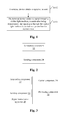
Fig. 1 shows a flowchart of a signal transmission method according to an embodiment of the present invention; -
Fig. 2 shows a structural diagram of a signal transmission apparatus according to an embodiment of the present invention; -
Fig. 3 shows a structural diagram of a signal transmission system according to an embodiment of the present invention; -
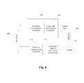
Fig. 4 is a structural diagram showing an architecture containing both power line communication and visible light communication according to an example embodiment of the present invention; -
Fig. 5 is a schematic diagram of an information processing component which integrates power line carrier and visible light communication according to an example embodiment of the present invention; and -
Fig. 6 is a schematic diagram which combines power line communication and visible light communication according to embodiment 1 of the present invention. - The present invention is described below with reference to the accompanying drawings and embodiments in detail. Note that, the embodiments of the present invention and the features of the embodiments can be combined with each other if there is no conflict.
- A signal transmission method is provided in this embodiment.
Fig. 1 is a flowchart of a signal transmission method according to an embodiment of the present invention. As shown inFig. 1 , the method includes steps S102 and S104. - In step S102, a terminal device acquires a signal to be sent.
- In step S104, the terminal device sends the signal through a visible light medium, wherein after being demodulated, the signal sent through the visible light medium is carried on a power line for transmission.
- In this embodiment, by means of the mentioned steps, the terminal device sends a signal to be sent through a visible light medium, and after being demodulated, the signal is carried on a power line for transmission, so that integration of the power line communication technique with visible light communication as a wireless access mode is realized. The problem in related technologies regarding the integration of the visible light communication as a wireless access manner with the power line communication technology is solved, the construction of the communication network can be more convenient and faster, and the advantages of the visible light communication and the power line communication technology are fully utilized.
- In an example embodiment, the terminal device may send the signal to be sent via an LED light source. The LED light source has a stronger transmission capability and a farther transmission distance, thus having a better communication effect.
- In an example embodiment, for a current terminal device, the signal may be sent via an LED light source (for example, a flashlight) on a camera of the terminal device. Since all the current terminal devices have a camera thereon, and the camera often has an LED flashlight thereon, this method is easy to implement and has good practicability.
- As an example implementation, after the terminal device sends a signal via a visible light medium, a light receiving device coupled to the power line may also receive a signal and demodulate the signal; and then the demodulated signal is carried on a power line carrier via a coupling transmitting device for transmission.
- In an example embodiment, the method for demodulating the signal may be implemented in the following manner: the signal received by the light receiving device is filtered and then demodulated, and the demodulated signal is decoded and then sent to a first processor, wherein the first processor is configured to convert the signal from a digital signal to a analogue signal.
- In an example embodiment, carrying the demodulated signal on the power line carrier via a coupling transmission device may be implemented in the following manner: the demodulated signal is processed via a first analogue front end, and then the demodulated signal is carried on a power line carrier for transmission via a coupling transmission device, wherein the first analogue front end includes a filter and an amplifier.
- In an example embodiment, after the demodulated signal is carried on a power line carrier for transmission via a coupling transmission device, the signal may be sent to an Internet via an access gateway. For example, the signal which is carried on the power line carrier may be sent to a second processor via a second analogue front end, and the signal is stored in the second processor and sent to the Internet via the access gateway, wherein the second processor is configured to convert the signal from an analogue signal to a digital signal, and the second analogue front end includes a filter and an amplifier.
- In an example embodiment, sending the signal to an Internet via an access gateway may be implemented via a wired mode and/or a wireless mode.
- In an example embodiment, the above-mentioned terminal device may be a cellphone, a tablet computer, a notebook computer, a fixed terminal with a camera and the like.
- Corresponding to the method, a signal transmission apparatus, located in the terminal device, is also provided in this embodiment. The apparatus is used for realizing the above-mentioned embodiments and example implementation, which is already explained and will not be described any more. As used hereinbelow, the term "component" can realize the combination of software and/or hardware with a predetermined function. Although the apparatus described in the embodiments below is preferably implemented with software, implementation with hardware, or a combination of software and hardware can also be conceived.
-
Fig. 2 shows a structural diagram of a signal transmission apparatus according to an embodiment of the present invention. As shown inFig. 2 , the apparatus includes: anacquisition component 22 and a sendingcomponent 24, and the components are described in detail below. - The
acquisition component 22 is configured to acquire a signal to be sent. The sendingcomponent 24, coupled to theacquisition component 22, is configured to send through a visible light medium the signal acquired by theacquisition component 22, wherein after being demodulated, the signal sent through the visible light medium is carried on a power line for transmission. - In this embodiment, by means of the mentioned components, the terminal device sends a signal to be sent acquired by the
acquisition component 22, through a visible light medium using the sendingcomponent 24, and after being demodulated, the signal is carried on a power line for transmission, so that the integration of the power line communication technique with visible light communication as a wireless access mode is realized. The problem in related technologies regarding the integration of the visible light communication as a wireless access manner with the power line communication technology is solved, the construction of the communication network can be more convenient and faster, and the advantages of the visible light communication and the power line communication technology are fully utilized. - In an example embodiment, the sending
component 24 may include: a sending unit, configured to send the signal through a light-emitting diode (LED) light source on a camera. - A signal transmission system is also provided in an embodiment.
Fig. 3 shows a structural diagram of a signal transmission system according to an embodiment of the present invention. As shown inFig. 3 , the system includes a signal transmission apparatus 20 as shown inFig. 2 , and further includes: aprocessing component 32, coupled to the sendingcomponent 24, configured to receive the signal via a light receiving device, and demodulate the signal; and a carryingcomponent 34, coupled to theprocessing component 32, configured to carry the demodulated signal on a power line carrier for transmission via a coupling transmission device. - Description is made below in combination an example embodiment, the example embodiment below is combined with the above-mentioned embodiments and example implementation thereof.
- In the example embodiment below, an architecture which integrates power line communication and visible light communication is provided. The architecture combines the power line carrier technique and visible light communication technique, realizes not only rapid and convenient networking but also the access to the Internet and the control of household appliance with widely distributed power lines and visible light as a medium.
- The visible light communication technique, combined with the power line carrier communication technique, can provide a convenient, rapid and more price-advantage networking mode for a home network and an office network.
-
Fig. 4 is a structural diagram showing an architecture containing both power line communication and visible light communication according to an example embodiment of the present invention. As shown inFig. 4 , the processing components in the architecture include: - 402, a terminal;
- 404, a visible light communication component (which implements the function of the processing component 32);
- 406, a power line communication component (which implements the function of the bearing component 34);
- 408, a power line;
- 410, a power line communication component;
- 412, an ADSL and other Internet access gateway;
- 414, the Internet.
- Based on the above-mentioned architecture, the flow of the terminal sending a signal may be as follows.
- For an uplink signal, the terminal sends the signal to the visible
light communication component 404 via a visible light medium; the visiblelight communication component 404 then demodulates the signal and sends the signal to the powerline communication component 406 for processing; the signal is transmitted over thepower line 408 and processed by the powerline communication component 410, and is accessed to theInternet 414 via the ADSL or otherInternet access device 412. - For a downlink signal, the digital signal of the
Internet 414 enters the powerline communication component 410 via the ADSL or other access devices, and enters the power line for transmission via the power line conversion component. -
Fig. 5 is a schematic diagram of an information processing component which integrates power line carrier and visible light communication according to an example embodiment of the present invention. As shown inFig. 5 , in an example embodiment, the following processing units are included. - 502, a terminal device;
- 504, a visible light communication processing unit, including a light receiver, a filtering, demodulation, decoding/coding, modulation and transmission device;
- 506, a processor, which processes, stores and performs data conversion on the received information;
- 508, analogue front end: including a filter, an amplifier, and a programmable gain amplifier;
- 510, coupling conversion unit;
- 512, coupling conversion unit;
- 514, analogue front end: responsible for the conversion of a power line carrier signal;
- 516, processor;
- 518, access gateway: including accessing the Internet in a wired or wireless mode;
- 520, the Internet; and
- 522, system power supply, available direct current power is acquired by the power line for use of communication components, such as the processor and amplifier.
- Based on the information processing component mentioned above, the information processing flow of the terminal may be as follows.
- I. uplink signal processing flow of the terminal:
- the terminal 502 sends a visible light signal via a visible light device;
- the visible light processing component 504 receives the visible signal via the light receiving device, and sends the data into the processor unit after the filtering, demodulation and decoding process;
- the
processor unit 506 processes the data, which then goes through the amplifier; - after being delivered by the
coupling conversion unit 510, the signal enters the power line carrier for delivery; - the
coupling conversion unit 512 receives the signal on the power line carrier, the signal is processed by the analoguefront end 514 and is converted into a digital signal by the processor and then stored, then goes through theaccess gateway 518 and accesses the Internet in a wired or wireless mode.
- II. downlink signal processing flow of the terminal:
- the signal of the
Internet 520 is accessed to theaccess gateway 518 in a wired or wireless mode, and is sent to theprocessor 516 for processing, and the modulated signal is filtered and amplified by the analoguefront end 514 and then subjected to the coupling conversion of thecoupling conversion unit 512; - after the coupling conversion of 512, the signal is processed by the filter and the programmable gain amplifier in the analogue
front end 508, and the digital signal is stored in the processor and then transmitted to theterminal device 502 via the visible light transmission unit 504.
- the signal of the
- A solution of a wireless terminal accessing an external network by means of power line communication in combination with visible light communication is provided in this example embodiment.
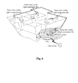
Fig. 6 is a schematic diagram which combines power line communication and visible light communication according to embodiment 1 of the present invention. As shown inFig. 6 , this architecture includes communication units as follows: - the
Internet 602; anInternet access gateway 604; a power line-visible light communication component 606, being able to receive a visible light signal and convert the visible light signal into a power line carrier signal; and power line-visiblelight communication components 608 located in other rooms. - The implementation and processing process of the solution is described as follows.
- A power line-visible
light communication components 608 located in another room receives a visible light signal sent by a terminal device (for example, communication devices, such as cellphone, tablet computer, notebook computer) via an LED flashlight of the camera;
the power line carrier signal is transmitted via the power line;
the power line carrier signal is received by the power line-visible light component 606 and is connected to a wireless router via a wired or wireless interface of the power line-visible light component 606, and is accessed to theInternet 602 via the Internet gateway device 604 (for example, access devices such as asymmetric digital subscriber line (ADSL)). - A solution of controlling room appliances via power line-visible light communication is provided in this example embodiment. The household appliances, including water heater, security and protection, lamplight, gas monitoring and the like, can be controlled via visible light communication. The steps of the solution are as follows:
- a terminal sends a signal for controlling an appliance;
- the power line-visible light component receives, demodulates and decodes the signal;
- a corresponding target device is found, the target device controls its action, which herein may include water heater opening time, lamplight brightness adjustment, gas monitoring, security and protection, in responsive to the signal of the terminal.
- In another embodiment, software is provided, the software is used for carrying out the technical solution described in the embodiment mentioned above and the example embodiment.
- In another embodiment, a storage medium is also provided. The software is stored on the storage medium, and the storage medium includes but is not limited to optical disks, floppy disks, hard disks, erasable storages, etc.
- Obviously, those skilled in the art should know that each of the mentioned components or steps of the present invention can be realized by universal computing devices; the components or steps can be focused on single computing device, or distributed on the network formed by multiple computing devices; selectively, they can be realized by the program codes which can be executed by the computing device; thereby, the components or steps can be stored in the storage device and executed by the computing device; and under some circumstances, the shown or described steps can be executed in different orders, or can be independently manufactured as each integrated circuit component, or multiple components or steps thereof can be manufactured to be single integrated circuit component, thus to be realized. In this way, the present invention is not restricted to any particular hardware and software combination.
- The descriptions above are only the preferable embodiment of the present invention, which are not used to restrict the present invention, for those skilled in the art, the present invention may have various changes and variations. Any amendments, equivalent substitutions, improvements, etc. within the principle of the present invention are all included in the scope of the protection defined by the appended claims of the present invention.
Claims (13)
- A signal transmission method, characterized by comprising:acquiring, by a terminal device, a signal to be sent; andsending, by the terminal device, the signal through a visible light medium, wherein after being demodulated, the signal sent through the visible light medium is carried on a power line for transmission.
- The method according to claim 1, characterized in that sending, by the terminal device, the signal through the visible light medium comprises:sending, by the terminal device, the signal through a light-emitting diode (LED) light source.
- The method according to claim 2, characterized in that sending, by the terminal device, the signal through the LED light source comprises:sending, by the terminal device, the signal through the LED light source on a camera.
- The method according to any one of claims 1 to 3, characterized in that after sending, by the terminal device, the signal through the visible light medium, the method further comprises:receiving the signal via a light receiving device, and demodulating the signal; andcarrying the demodulated signal on a power line carrier for transmission via a coupling transmission device.
- The method according to claim 4, characterized in that demodulating the signal comprises:filtering the signal received by the light receiving device, demodulating the filtered signal, decoding the demodulated signal and sending the decoded signal to a first processor, wherein the first processor is configured to convert the signal from a digital signal to an analogue signal.
- The method according to claim 4, characterized in that carrying the demodulated signal on the power line carrier for transmission via the coupling transmission device comprises:processing the demodulated signal via a first analogue front end, and then carrying the demodulated signal on the power line carrier for transmission via the coupling transmission device, wherein the first analogue front end comprises a filter and an amplifier.
- The method according to any one of claims 4 to 6, characterized in that after carrying the demodulated signal on the power line carrier for transmission via the coupling transmission device, the method further comprises:sending the signal to an Internet via an access gateway.
- The method according to claim 7, characterized in that sending the signal to the Internet via the access gateway comprises:sending the signal which is carried on the power line carrier to a second processor via a second analogue front end, and storing the signal in the second processor and sending the signal to the Internet via the access gateway, wherein the second processor is configured to convert the signal from an analogue signal to a digital signal, and the second analogue front end comprises a filter and an amplifier.
- The method according to claim 7 or 8, characterized in that sending the signal to the Internet via the access gateway comprises at least one of the following modes: a wired mode and a wireless mode.
- The method according to any one of claims 1-9, characterized in that the terminal device comprises at least one of the following: a cellphone, a tablet computer, a notebook computer, and a fixed terminal with a camera.
- A signal transmission apparatus, located in a terminal device, characterized in that the signal transmission apparatus comprises:an acquisition component, configured to acquire a signal to be sent; anda sending component, configured to send the signal through a visible light medium, wherein after being demodulated, the signal sent through the visible light medium is carried on a power line for transmission.
- The device according to claim 11, characterized in that the sending component comprises:a sending unit, configured to send the signal through a light-emitting diode (LED) light source on a camera.
- A signal transmission system, characterized by comprising a transmission apparatus as claimed in claim 11 or 12, and further comprising:a processing component, configured to receive the signal via a light receiving device, and demodulate the signal; anda carrying component, configured to carry the demodulated signal on a power line carrier for transmission via a coupling transmission device.
Applications Claiming Priority (2)
| Application Number | Priority Date | Filing Date | Title |
|---|---|---|---|
| CN201210351822.5A CN103684529B (en) | 2012-09-20 | 2012-09-20 | Method for transmitting signals and device |
| PCT/CN2013/078995 WO2013174307A1 (en) | 2012-09-20 | 2013-07-08 | Signal transmission method and apparatus |
Publications (2)
| Publication Number | Publication Date |
|---|---|
| EP2899902A1 true EP2899902A1 (en) | 2015-07-29 |
| EP2899902A4 EP2899902A4 (en) | 2016-06-22 |
Family
ID=49623162
Family Applications (1)
| Application Number | Title | Priority Date | Filing Date |
|---|---|---|---|
| EP13793457.6A Withdrawn EP2899902A4 (en) | 2012-09-20 | 2013-07-08 | Signal transmission method and apparatus |
Country Status (4)
| Country | Link |
|---|---|
| US (1) | US9461741B2 (en) |
| EP (1) | EP2899902A4 (en) |
| CN (1) | CN103684529B (en) |
| WO (1) | WO2013174307A1 (en) |
Cited By (1)
| Publication number | Priority date | Publication date | Assignee | Title |
|---|---|---|---|---|
| CN104980219A (en) * | 2015-08-04 | 2015-10-14 | 北京奥普泰克科技有限责任公司 | Visible light communication system based on FSK modulation and power line carrier |
Families Citing this family (13)
| Publication number | Priority date | Publication date | Assignee | Title |
|---|---|---|---|---|
| CN104202438A (en) * | 2014-07-30 | 2014-12-10 | 惠州Tcl移动通信有限公司 | An interface adapter, a terminal, and a visible light communication system |
| CN104104440B (en) * | 2014-08-07 | 2017-02-22 | 中国人民解放军信息工程大学 | Visible light communication based indoor Femtocell networking communication system |
| WO2016145560A1 (en) * | 2015-03-13 | 2016-09-22 | 华为技术有限公司 | Gateway side power line communication subsystem, gateway and coupling and decoupling apparatus |
| CN106327852A (en) * | 2015-06-25 | 2017-01-11 | � 刘 | Mobile phone controlled electrical appliance system and method based on flash lamp |
| CN106066096A (en) * | 2016-06-01 | 2016-11-02 | 苏州杰姆斯特机械有限公司 | The remotely light-operated Intelligent heating shower system of a kind of Multi net voting |
| CN106788600A (en) * | 2016-12-23 | 2017-05-31 | 福建省亿坤通信股份有限公司 | A kind of visible light communication system and method based on carrier communication chip |
| CN106992799A (en) * | 2016-12-23 | 2017-07-28 | 中国人民解放军信息工程大学 | A kind of visible light communication system with WIFI communication functions |
| CN106850059A (en) * | 2016-12-23 | 2017-06-13 | 国网福建省电力有限公司宁德供电公司 | Visible light communication radio frequency ascending communication system and method based on carrier communication chip |
| CN106877928A (en) * | 2016-12-23 | 2017-06-20 | 中国人民解放军信息工程大学 | A kind of visible light communication system and method based on power line communication |
| CN107547133B (en) * | 2017-07-24 | 2020-04-10 | 上海师范大学 | PLC-VLC transmission method based on OFDM technology for indoor communication system |
| IT201700101065A1 (en) * | 2017-09-08 | 2019-03-08 | Slux Sagl | DATA TRANSMISSION SYSTEM USING OPTICAL RADIATION USING DIFFUSION THROUGH CONVOGULATED WAVES AND ASSOCIATED METHOD |
| EP3729689A1 (en) * | 2017-09-08 | 2020-10-28 | Slux Sagl | System for transmitting data by means of optical radiation by means of diffusion by power lines and associated method |
| TWI737403B (en) * | 2020-07-15 | 2021-08-21 | 南臺學校財團法人南臺科技大學 | Intelligent detection device |
Family Cites Families (12)
| Publication number | Priority date | Publication date | Assignee | Title |
|---|---|---|---|---|
| WO2002015438A1 (en) * | 2000-08-15 | 2002-02-21 | Lockheed Martin Corporation | Infrared data communication system |
| DE60316178T2 (en) * | 2002-10-24 | 2008-06-05 | Nakagawa Laboratories, Inc. | COMMUNICATION DEVICE WITH ILLUMINATING LIGHT |
| JP2007274566A (en) * | 2006-03-31 | 2007-10-18 | Nakagawa Kenkyusho:Kk | Illumination light communication device |
| TWI349466B (en) * | 2007-10-12 | 2011-09-21 | Alpha Networks Inc | Power line adapter and method for controlling power line adepter to power saving mode |
| CN101232327B (en) * | 2007-10-30 | 2011-05-18 | 华东理工大学 | Visible light space division multiple access multichannel communication system |
| CN101599781A (en) * | 2008-06-06 | 2009-12-09 | 许浩坤 | The ZIGBEE transfer power line carrier wave gateway technology |
| US20120001567A1 (en) * | 2009-09-30 | 2012-01-05 | Firefly Green Technologies, Inc. | Lighting Control System |
| US8494374B2 (en) * | 2010-06-14 | 2013-07-23 | Streamlight, Inc. | Portable light providing illumination and data |
| CN101945309A (en) * | 2010-09-02 | 2011-01-12 | 李淑英 | Method, system and device for realizing bidirectional communication by combining passive optical network with power-line carrier |
| CN102081835A (en) * | 2010-11-18 | 2011-06-01 | 广州广联数字家庭产业技术研究院 | Remote meter reading system based on power carrier |
| CN102624451A (en) * | 2011-01-27 | 2012-08-01 | 郭丰亮 | Power line carrier-based LED visible light communication system |
| CN102624455A (en) | 2012-04-25 | 2012-08-01 | 武汉华炬光电有限公司 | LED visible light wireless communication system for mine |
-
2012
- 2012-09-20 CN CN201210351822.5A patent/CN103684529B/en not_active Expired - Fee Related
-
2013
- 2013-07-08 WO PCT/CN2013/078995 patent/WO2013174307A1/en active Application Filing
- 2013-07-08 US US14/429,533 patent/US9461741B2/en active Active
- 2013-07-08 EP EP13793457.6A patent/EP2899902A4/en not_active Withdrawn
Cited By (1)
| Publication number | Priority date | Publication date | Assignee | Title |
|---|---|---|---|---|
| CN104980219A (en) * | 2015-08-04 | 2015-10-14 | 北京奥普泰克科技有限责任公司 | Visible light communication system based on FSK modulation and power line carrier |
Also Published As
| Publication number | Publication date |
|---|---|
| US20150304028A1 (en) | 2015-10-22 |
| EP2899902A4 (en) | 2016-06-22 |
| CN103684529B (en) | 2018-01-23 |
| US9461741B2 (en) | 2016-10-04 |
| CN103684529A (en) | 2014-03-26 |
| WO2013174307A1 (en) | 2013-11-28 |
Similar Documents
| Publication | Publication Date | Title |
|---|---|---|
| US9461741B2 (en) | Signal transmission method and apparatus | |
| CN107911166B (en) | Visible light/radio frequency hybrid cooperative communication method based on wireless energy harvesting and non-orthogonal multiple access | |
| US20080304833A1 (en) | Illumination Light Wireless Communication System | |
| WO2019100789A1 (en) | Wifi and lifi hybrid type-based communication system | |
| US9906297B2 (en) | Method and system for implementing visible-light communication, sending apparatus, and receiving apparatus | |
| CN103427903A (en) | Visible light communication system based on wireless access point | |
| CN103023567A (en) | Visible light communication method, device and system | |
| CN104836709A (en) | Intelligent household system based on power carrier | |
| Tiwari et al. | Color coded multiple access scheme for bidirectional multiuser visible light communications in smart home technologies | |
| CN207283557U (en) | Visible light communication Transmission system based on LED light | |
| CN205596120U (en) | High -speed LED visible light communication system and receiving arrangement | |
| CN103200082A (en) | Ethernet radio network gateway based on Z-Wave technology | |
| Uysal | Visible light communications: from theory to industrial standardization | |
| CN104980218A (en) | Optical-filter-free visible light communication system | |
| CN103812560A (en) | Hybrid communication system based on visible lights and radio frequency | |
| Wu | Free space optical networking with visible light: A multi-hop multi-access solution | |
| KR102010640B1 (en) | Apparatus of multi-user Full-duplex visible light communication | |
| CN103974509A (en) | Method and system for intelligently controlling LEDs | |
| CN103728934A (en) | Intelligent home system | |
| CN109361459A (en) | A kind of optic communication intelligence system and method | |
| CN111354179A (en) | Intelligent household appliance control system based on power line carrier communication and infrared remote control | |
| CN106953691B (en) | Uplink and downlink time division multiplexing visible light full duplex communication system and method | |
| RU2698403C1 (en) | Method of wireless access to the internet through visible and infrared light and a device for its implementation | |
| CN213365772U (en) | Intelligent household appliance control system and lighting lamp for remotely controlling household appliances | |
| CN204090202U (en) | LED intelligent control system |
Legal Events
| Date | Code | Title | Description |
|---|---|---|---|
| PUAI | Public reference made under article 153(3) epc to a published international application that has entered the european phase |
Free format text: ORIGINAL CODE: 0009012 |
|
| 17P | Request for examination filed |
Effective date: 20150325 |
|
| AK | Designated contracting states |
Kind code of ref document: A1 Designated state(s): AL AT BE BG CH CY CZ DE DK EE ES FI FR GB GR HR HU IE IS IT LI LT LU LV MC MK MT NL NO PL PT RO RS SE SI SK SM TR |
|
| AX | Request for extension of the european patent |
Extension state: BA ME |
|
| DAX | Request for extension of the european patent (deleted) | ||
| RA4 | Supplementary search report drawn up and despatched (corrected) |
Effective date: 20160520 |
|
| RIC1 | Information provided on ipc code assigned before grant |
Ipc: H04B 10/116 20130101AFI20160513BHEP Ipc: H04B 3/54 20060101ALI20160513BHEP |
|
| 17Q | First examination report despatched |
Effective date: 20171201 |
|
| STAA | Information on the status of an ep patent application or granted ep patent |
Free format text: STATUS: THE APPLICATION IS DEEMED TO BE WITHDRAWN |
|
| 18D | Application deemed to be withdrawn |
Effective date: 20200911 |