EP2899851A2 - Rotor for motor, motor having the same and method for manufacturing the same - Google Patents
Rotor for motor, motor having the same and method for manufacturing the same Download PDFInfo
- Publication number
- EP2899851A2 EP2899851A2 EP15152364.4A EP15152364A EP2899851A2 EP 2899851 A2 EP2899851 A2 EP 2899851A2 EP 15152364 A EP15152364 A EP 15152364A EP 2899851 A2 EP2899851 A2 EP 2899851A2
- Authority
- EP
- European Patent Office
- Prior art keywords
- rotor
- rotor core
- motor
- tube
- magnets
- Prior art date
- Legal status (The legal status is an assumption and is not a legal conclusion. Google has not performed a legal analysis and makes no representation as to the accuracy of the status listed.)
- Ceased
Links
Images



Classifications
-
- H—ELECTRICITY
- H02—GENERATION; CONVERSION OR DISTRIBUTION OF ELECTRIC POWER
- H02K—DYNAMO-ELECTRIC MACHINES
- H02K1/00—Details of the magnetic circuit
- H02K1/06—Details of the magnetic circuit characterised by the shape, form or construction
- H02K1/22—Rotating parts of the magnetic circuit
- H02K1/28—Means for mounting or fastening rotating magnetic parts on to, or to, the rotor structures
-
- H—ELECTRICITY
- H02—GENERATION; CONVERSION OR DISTRIBUTION OF ELECTRIC POWER
- H02K—DYNAMO-ELECTRIC MACHINES
- H02K1/00—Details of the magnetic circuit
- H02K1/04—Details of the magnetic circuit characterised by the material used for insulating the magnetic circuit or parts thereof
-
- H—ELECTRICITY
- H02—GENERATION; CONVERSION OR DISTRIBUTION OF ELECTRIC POWER
- H02K—DYNAMO-ELECTRIC MACHINES
- H02K1/00—Details of the magnetic circuit
- H02K1/06—Details of the magnetic circuit characterised by the shape, form or construction
- H02K1/22—Rotating parts of the magnetic circuit
- H02K1/27—Rotor cores with permanent magnets
- H02K1/2706—Inner rotors
- H02K1/272—Inner rotors the magnetisation axis of the magnets being perpendicular to the rotor axis
- H02K1/274—Inner rotors the magnetisation axis of the magnets being perpendicular to the rotor axis the rotor consisting of two or more circumferentially positioned magnets
-
- H—ELECTRICITY
- H02—GENERATION; CONVERSION OR DISTRIBUTION OF ELECTRIC POWER
- H02K—DYNAMO-ELECTRIC MACHINES
- H02K1/00—Details of the magnetic circuit
- H02K1/06—Details of the magnetic circuit characterised by the shape, form or construction
- H02K1/22—Rotating parts of the magnetic circuit
- H02K1/28—Means for mounting or fastening rotating magnetic parts on to, or to, the rotor structures
- H02K1/30—Means for mounting or fastening rotating magnetic parts on to, or to, the rotor structures using intermediate parts, e.g. spiders
-
- H—ELECTRICITY
- H02—GENERATION; CONVERSION OR DISTRIBUTION OF ELECTRIC POWER
- H02K—DYNAMO-ELECTRIC MACHINES
- H02K15/00—Processes or apparatus specially adapted for manufacturing, assembling, maintaining or repairing of dynamo-electric machines
- H02K15/02—Processes or apparatus specially adapted for manufacturing, assembling, maintaining or repairing of dynamo-electric machines of stator or rotor bodies
-
- Y—GENERAL TAGGING OF NEW TECHNOLOGICAL DEVELOPMENTS; GENERAL TAGGING OF CROSS-SECTIONAL TECHNOLOGIES SPANNING OVER SEVERAL SECTIONS OF THE IPC; TECHNICAL SUBJECTS COVERED BY FORMER USPC CROSS-REFERENCE ART COLLECTIONS [XRACs] AND DIGESTS
- Y10—TECHNICAL SUBJECTS COVERED BY FORMER USPC
- Y10T—TECHNICAL SUBJECTS COVERED BY FORMER US CLASSIFICATION
- Y10T29/00—Metal working
- Y10T29/49—Method of mechanical manufacture
- Y10T29/49002—Electrical device making
- Y10T29/49009—Dynamoelectric machine
- Y10T29/49012—Rotor
Definitions
- Embodiments of the present invention relate to a rotor for a motor, a motor having the same and a method for manufacturing the same and, more specifically, to a rotor for a motor having a rotor tube, a motor having the same and a method for manufacturing the same.
- Motors are devices that convert electric energy to rotational energy using a force applied to a conductor in a magnetic field. Recently, as applications of the motors increase, functions of the motors become important. Particularly, with rapid electronization of automobiles, a demand for the motors applied to a steering system, a braking system and a design system, etc. is increased dramatically.
- the motors are provided with a shaft formed to be rotatable, a rotor coupled with the shaft, and a stator fixed inside a housing, wherein the stator is installed along a circumference of the rotor with a gap.
- a coil forming a rotational magnetic field is wound around the stator so as to induce an electric interaction with the rotor to rotate the rotor.
- the shaft is rotated to create or assist a braking force or a steering force.
- the rotor may be provided with a rotor tube in a tubular form, a rotor core coupled to a circumferential surface of the rotor tube, and magnets.
- the shaft may be press-fitted into the rotor tube.
- the rotor core may be press-fitted around the circumferential surface of the rotor tube.
- the rotor tube may be easily deformed while the rotor core is coupled to the rotor tube, because the rotor tube is thin.
- inner and outer diameters of the rotor tube may be changed so that a quality of the motor may become an issue.
- chips may occur while the rotor core is press-fitted around the rotor tube.
- a slip may occur between the rotor tube and the rotor core when the motor rotates at a high speed.
- a problem of separation of the rotor core from the rotor tube may occur.
- an object of the present invention is to provide a rotor for a motor, a motor having the rotor, and a method for manufacturing the rotor, capable of preventing a rotor tube from being deformed in the process of assembling the rotor.
- another object of the present invention is to provide a rotor for a motor, a motor having the rotor, and a method for manufacturing the rotor, capable of preventing chips from occurring in the process of assembling the rotor.
- yet another object of the present invention is to provide a rotor for a motor, a motor having the rotor, and a method for manufacturing the rotor, capable of preventing a slip from occurring between a rotor tube and a rotor core.
- a rotor for a motor which includes: a rotor tube having at least two step regions whose diameters are different from each other; a rotor core disposed on a circumferential surface of the rotor tube and integrally formed with the rotor tube; and magnets disposed on the circumferential surface of the rotor core.
- the rotor tube and the rotor core may be integrally formed by any one of forging, sintering and pressing processes.
- a plurality of discrete slots may be formed in a circumference of the rotor core, and the magnets maybe coupled to the respective slots.
- the slots may be formed between a plurality of protrusions that are formed to protrude from the circumference surface of the rotor core in an elongated form in a longitudinal direction and disposed spaced apart from each other along a circumference of the rotor core.
- the magnets may be formed in a plate shape whose thickness direction is set to a radial direction of the rotor core.
- the rotor may further include a mold surrounding the rotor core.
- the at least two step regions may be reduced in diameter toward bottoms thereof.
- a motor that includes: a stator; a rotor including a rotor tube that is disposed within the stator and has at least two step regions whose diameters are different from each other, a rotor core that is formed on a circumferential surface of the rotor tube and integrally formed with the rotor tube, and magnets coupled to the rotor core; and a shaft coupled inside the rotor tube.
- the rotor tube and the rotor core may be formed by any one of forging, sintering and pressing processes.
- a plurality of slots may be divided and formed on a circumference of the rotor core, and the magnets may be coupled into the respective slots.
- the slots may be formed between a plurality of protrusions that are formed to protrude from the circumference surface of the rotor core in an elongated form in a longitudinal direction and are disposed spaced apart from each other along the circumference of the rotor core.
- the magnets may be formed in a plate shape whose thickness direction is set to a radial direction of the rotor core.
- the motor may further include a mold surrounding the rotor core.
- the at least two step regions may be reduced in diameter toward bottoms thereof.
- a method for manufacturing a rotor including: integrally forming a rotor tube and a rotor core; coupling magnets to the rotor core; and molding the rotor core and the magnets.
- FIG. 1 is a view illustrating a motor according to a preferred embodiment of the present invention
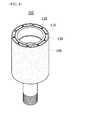
- FIG. 2 is a view illustrating a rotor tube and a rotor core integrally formed with each other.
- FIGS. 1 and 2 are to clearly illustrate only principal features to help conceptual understating of the present invention. As a result, the illustrations are expected to be variously modified, and the scope of the present invention is not necessarily limited to a specific shape illustrated in the figures.
- a motor 10 may include a rotor 100, a stator 200 and a shaft 300.
- the rotor 100 may include a rotor tube 110, a rotor core 120, and magnets 130.
- the rotor tube 110 maybe disposed inside the stator 200, and the rotor core 120 maybe formed on a circumference surface of the rotor tube 110.
- the shaft 300 may be coupled inside of the rotor tube 110 in a press-fitting way.
- a fixing block having threads formed on inner side thereof may be press-fitted into the rotor tube 110, and the shaft 300 may be screwed to the fixing block.
- a bearing 1 may be coupled to a circumference surface of a lower portion of the rotor tube 110. The bearing 1 serves to rotationally support the rotor tube 110 and supporting an axial load.
- a washer 2 supporting the bearing 1 under the bearing 1 may be screwed to the shaft 300.
- a threaded end 111 may be formed on an end portion of the shaft 300 to be screwed with the washer 2.
- the rotor tube 110 and the rotor core 120 maybe integrally formed with each other.
- the rotor tube 110 and the rotor core 120 may be formed by any one of forging, sintering and pressing processing processes.
- the forging process means a process of applying a static or dynamic pressure during a smooth plastic flow to refine crystal grains, homogenizing a structure, and simultaneously forming into a predetermined shape.
- the sintering process means a process of sintering a powder compact formed under pressure
- the pressing process means plastic working using a press.
- the rotor tube 110 and the rotor core 120 is integrally formed, deformation occurring in the process of assembling the rotor tube 110 and the rotor core 120 can be fundamentally prevented. Further, chips can be prevented from occurring, because the press-fitting process is not required. In addition, it is possible to prevent a slip from occurring between the rotor tube 110 and the rotor core 120.
- a plurality of slots 121 may be divided and formed in a circumference of the rotor core 120.
- the slots 121 may be formed between protrusions 122.
- a plurality of protrusions 122 maybe formed to protrude from the circumference surface of the rotor core 120, formed in an elongated form in a longitudinal direction, and disposed spaced apart from each other along the circumference of the rotor core 120.
- the rotor tube 110 may be formed in the shape of a cylinder in which the shaft 120 can be mounted.
- the rotor tube 110 may be reduced in diameter in a stepwise manner as it goes down in a longitudinal direction thereof so that a plurality of step regions can be formed. This is for supporting an axial load through a raised portion formed between the step regions.
- the rotor core 120 may be integrally formed with any one of the step regions.
- FIG. 3 is a view illustrating magnets attached to the rotor core.
- magnets 130 are coupled into the respective slots 121.
- the magnets 130 are formed in the shape of a plate whose thickness direction is set to a radial direction of the rotor core 120.
- the magnets 130 may be coupled into the slots 121 by an adhesive.
- FIG. 4 is a view illustrating a molded state of the rotor core and the magnets.
- a mold 140 may couple the rotor tube 110 and the rotor core 120.
- the mold 140 is formed to surround the circumference of the rotor core 120.
- the mold 140 may be formed to surround the entire circumference of the rotor core 120 as illustrated in FIG. 4 , but present invention is not limited thereto.
- the mold 140 may be formed only on a partial region of the rotor core 120.
- the thicknesses of the magnets 130 are greater or smaller than the thicknesses of the protrusions 122, a space may be formed between the magnets 130 or the protrusions 122, and may be filled with the mold 140.
- the mold has a non-uniform thickness.
- the mold 140 may surround the circumferential portion of the rotor core 120 at a substantially uniform thickness.
- the mold 140 surrounds a lateral portion of the rotor core 120 in FIG. 4
- present invention is not limited thereto, and the mold 140 may cover an upper surface portion of the rotor core 120. In this case, not only radial separation but also axial separation or movement of the magnets 130 can be prevented.
- FIG. 5 is a flow chart describing a method for manufacturing a motor according to another preferred embodiment of the present invention.
- the rotor tube 110 and the rotor core 120 maybe integrally formed first (S100).
- the magnets 130 may be coupled into the slots 121 of the rotor tube 110 (S200).
- the rotor core 120 and the magnets 130 maybe fixed by molding (S300).
Landscapes
- Engineering & Computer Science (AREA)
- Power Engineering (AREA)
- Manufacturing & Machinery (AREA)
- Permanent Field Magnets Of Synchronous Machinery (AREA)
- Manufacture Of Motors, Generators (AREA)
- Iron Core Of Rotating Electric Machines (AREA)
Abstract
Description
- This application claims priority to and the benefit of Korean Patent Application No.
2014-0008353, filed on January 23, 2014 - Embodiments of the present invention relate to a rotor for a motor, a motor having the same and a method for manufacturing the same and, more specifically, to a rotor for a motor having a rotor tube, a motor having the same and a method for manufacturing the same.
- Motors are devices that convert electric energy to rotational energy using a force applied to a conductor in a magnetic field. Recently, as applications of the motors increase, functions of the motors become important. Particularly, with rapid electronization of automobiles, a demand for the motors applied to a steering system, a braking system and a design system, etc. is increased dramatically.
- Conventionally, the motors are provided with a shaft formed to be rotatable, a rotor coupled with the shaft, and a stator fixed inside a housing, wherein the stator is installed along a circumference of the rotor with a gap. A coil forming a rotational magnetic field is wound around the stator so as to induce an electric interaction with the rotor to rotate the rotor. When the rotor is rotated, the shaft is rotated to create or assist a braking force or a steering force.
- Here, the rotor may be provided with a rotor tube in a tubular form, a rotor core coupled to a circumferential surface of the rotor tube, and magnets. The shaft may be press-fitted into the rotor tube. The rotor core may be press-fitted around the circumferential surface of the rotor tube.
- Meanwhile, the rotor tube may be easily deformed while the rotor core is coupled to the rotor tube, because the rotor tube is thin. When the deformation of the rotor tube occurs, inner and outer diameters of the rotor tube may be changed so that a quality of the motor may become an issue. In addition, there is a problem that chips may occur while the rotor core is press-fitted around the rotor tube.
- In addition, a slip may occur between the rotor tube and the rotor core when the motor rotates at a high speed. When the slip is sustained, a problem of separation of the rotor core from the rotor tube may occur.
- Accordingly, the present invention has been made keeping in mind that above problems occurring in the prior art, and an object of the present invention is to provide a rotor for a motor, a motor having the rotor, and a method for manufacturing the rotor, capable of preventing a rotor tube from being deformed in the process of assembling the rotor.
- In addition, another object of the present invention is to provide a rotor for a motor, a motor having the rotor, and a method for manufacturing the rotor, capable of preventing chips from occurring in the process of assembling the rotor.
- Further, yet another object of the present invention is to provide a rotor for a motor, a motor having the rotor, and a method for manufacturing the rotor, capable of preventing a slip from occurring between a rotor tube and a rotor core.
- Objects of the present invention should not be construed as limited to the objects described above, and other objects not described herein will be readily understood by a person skilled in the art upon consideration of the following detailed description of the invention.
- To achieve the objects described above, according to an aspect of the present invention, there is provided a rotor for a motor, which includes: a rotor tube having at least two step regions whose diameters are different from each other; a rotor core disposed on a circumferential surface of the rotor tube and integrally formed with the rotor tube; and magnets disposed on the circumferential surface of the rotor core.
- Preferentially, the rotor tube and the rotor core may be integrally formed by any one of forging, sintering and pressing processes.
- Preferentially, a plurality of discrete slots may be formed in a circumference of the rotor core, and the magnets maybe coupled to the respective slots.
- Preferentially, the slots may be formed between a plurality of protrusions that are formed to protrude from the circumference surface of the rotor core in an elongated form in a longitudinal direction and disposed spaced apart from each other along a circumference of the rotor core.
- Preferentially, the magnets may be formed in a plate shape whose thickness direction is set to a radial direction of the rotor core.
- Preferentially, the rotor may further include a mold surrounding the rotor core.
- Preferentially, the at least two step regions may be reduced in diameter toward bottoms thereof.
- According to another aspect of the present invention, there is provided a motor that includes: a stator; a rotor including a rotor tube that is disposed within the stator and has at least two step regions whose diameters are different from each other, a rotor core that is formed on a circumferential surface of the rotor tube and integrally formed with the rotor tube, and magnets coupled to the rotor core; and a shaft coupled inside the rotor tube.
- Preferentially, the rotor tube and the rotor core may be formed by any one of forging, sintering and pressing processes.
- Preferentially, a plurality of slots may be divided and formed on a circumference of the rotor core, and the magnets may be coupled into the respective slots.
- Preferentially, the slots may be formed between a plurality of protrusions that are formed to protrude from the circumference surface of the rotor core in an elongated form in a longitudinal direction and are disposed spaced apart from each other along the circumference of the rotor core.
- Preferentially, the magnets may be formed in a plate shape whose thickness direction is set to a radial direction of the rotor core.
- Preferentially, the motor may further include a mold surrounding the rotor core.
- Preferentially, the at least two step regions may be reduced in diameter toward bottoms thereof.
- According to yet another aspect of the present invention, there is provided a method for manufacturing a rotor including: integrally forming a rotor tube and a rotor core; coupling magnets to the rotor core; and molding the rotor core and the magnets.
- According to embodiments of the present invention, there is provided an advantageous effect of preventing the rotor tube from being deformed in the process of assembling the rotor tube and the rotor core by integrally forming the rotor tube and the rotor core.
- In addition, according to an embodiment of the present invention, there is provided another advantageous effect of preventing chips from being formed by integrally shaping the rotor tube and the rotor core.
- Further, according to an embodiment of the present invention, there is provided yet another advantageous effect of preventing a slip from occurring between the rotor tube and the rotor core and of saving a manufacturing cost by replacing two parts with one part.
-
-
FIG. 1 is a view illustrating a motor according to a preferred embodiment of the present invention. -
FIG. 2 is a view illustrating a rotor tube and a rotor core integrally formed with each other. -
FIG. 3 is a view illustrating magnets attached to the rotor core. -
FIG. 4 is a view illustrating a molded state of the rotor core and the magnets. -
FIG. 5 is a flow chart describing a method for manufacturing a motor according to another preferred embodiment of the present invention. - Hereafter, exemplary embodiments of the present invention will be described in detail with reference to the accompanying drawings. These and other objects, advantages and features of the invention will become apparent from the following more detailed description taken in conjunction with the accompanying drawings. The terms or words used in the specification and claims are not to be interpreted by their typical or dictionary meanings but their meanings and concepts should be construed in conformity with the technical idea of the invention, based on the principle that the inventor can properly define the concepts of the terms so as to explain the invention in the best manner. Detailed descriptions of well-known functions and structures incorporated herein may be omitted to avoid obscuring the subject matter of the present invention.
-
FIG. 1 is a view illustrating a motor according to a preferred embodiment of the present invention, andFIG. 2 is a view illustrating a rotor tube and a rotor core integrally formed with each other.FIGS. 1 and2 are to clearly illustrate only principal features to help conceptual understating of the present invention. As a result, the illustrations are expected to be variously modified, and the scope of the present invention is not necessarily limited to a specific shape illustrated in the figures. - First, referring to
FIG. 1 , amotor 10 according to a preferred embodiment of the present invention may include arotor 100, astator 200 and ashaft 300. - The
rotor 100 may include arotor tube 110, arotor core 120, andmagnets 130. Therotor tube 110 maybe disposed inside thestator 200, and therotor core 120 maybe formed on a circumference surface of therotor tube 110. Theshaft 300 may be coupled inside of therotor tube 110 in a press-fitting way. A fixing block having threads formed on inner side thereof may be press-fitted into therotor tube 110, and theshaft 300 may be screwed to the fixing block. Abearing 1 may be coupled to a circumference surface of a lower portion of therotor tube 110. Thebearing 1 serves to rotationally support therotor tube 110 and supporting an axial load. Awasher 2 supporting thebearing 1 under thebearing 1 may be screwed to theshaft 300. A threadedend 111 may be formed on an end portion of theshaft 300 to be screwed with thewasher 2. - Referring to
FIG. 2 , therotor tube 110 and therotor core 120 maybe integrally formed with each other. Therotor tube 110 and therotor core 120 may be formed by any one of forging, sintering and pressing processing processes. Herein, the forging process means a process of applying a static or dynamic pressure during a smooth plastic flow to refine crystal grains, homogenizing a structure, and simultaneously forming into a predetermined shape. The sintering process means a process of sintering a powder compact formed under pressure, and the pressing process means plastic working using a press. - Since the
rotor tube 110 and therotor core 120 is integrally formed, deformation occurring in the process of assembling therotor tube 110 and therotor core 120 can be fundamentally prevented. Further, chips can be prevented from occurring, because the press-fitting process is not required. In addition, it is possible to prevent a slip from occurring between therotor tube 110 and therotor core 120. - A plurality of
slots 121 may be divided and formed in a circumference of therotor core 120. Theslots 121 may be formed betweenprotrusions 122. A plurality ofprotrusions 122 maybe formed to protrude from the circumference surface of therotor core 120, formed in an elongated form in a longitudinal direction, and disposed spaced apart from each other along the circumference of therotor core 120. - The
rotor tube 110 may be formed in the shape of a cylinder in which theshaft 120 can be mounted. Therotor tube 110 may be reduced in diameter in a stepwise manner as it goes down in a longitudinal direction thereof so that a plurality of step regions can be formed. This is for supporting an axial load through a raised portion formed between the step regions. Therotor core 120 may be integrally formed with any one of the step regions. -
FIG. 3 is a view illustrating magnets attached to the rotor core. - As illustrated in
FIGS. 2 and3 ,magnets 130 are coupled into therespective slots 121. Themagnets 130 are formed in the shape of a plate whose thickness direction is set to a radial direction of therotor core 120. Themagnets 130 may be coupled into theslots 121 by an adhesive. -
FIG. 4 is a view illustrating a molded state of the rotor core and the magnets. - Referring to
FIG. 4 , amold 140 may couple therotor tube 110 and therotor core 120. Themold 140 is formed to surround the circumference of therotor core 120. Themold 140 may be formed to surround the entire circumference of therotor core 120 as illustrated inFIG. 4 , but present invention is not limited thereto. Themold 140 may be formed only on a partial region of therotor core 120. When the thicknesses of themagnets 130 are greater or smaller than the thicknesses of theprotrusions 122, a space may be formed between themagnets 130 or theprotrusions 122, and may be filled with themold 140. In this case, the mold has a non-uniform thickness. In addition, when themagnets 130 and theprotrusions 122 have the same thickness, themold 140 may surround the circumferential portion of therotor core 120 at a substantially uniform thickness. - Although the
mold 140 surrounds a lateral portion of therotor core 120 inFIG. 4 , present invention is not limited thereto, and themold 140 may cover an upper surface portion of therotor core 120. In this case, not only radial separation but also axial separation or movement of themagnets 130 can be prevented. -
FIG. 5 is a flow chart describing a method for manufacturing a motor according to another preferred embodiment of the present invention. - Referring
FIGS. 2 to 5 , in the method for manufacturing the motor according to another preferred embodiment of the present invention, therotor tube 110 and therotor core 120 maybe integrally formed first (S100). - Then, the
magnets 130 may be coupled into theslots 121 of the rotor tube 110 (S200). - Next, the
rotor core 120 and themagnets 130 maybe fixed by molding (S300). - The rotor for motor, the motor having the same and the method for manufacturing the rotor according to the preferred embodiments of the present invention have been described above in detail with reference to the attached drawings.
- The above description of the present disclosure is provided for the purpose of illustration, and it would be understood by those skilled in the art that various modifications, changes and substitutions may be made without changing technical conception and essential features of the present disclosure. Therefore, it should be noted that the forgoing embodiments are merely illustrative in all aspects and are not to be construed as limiting the invention. The scope of the invention is defined by the appended claims rather than the detailed description of the invention. All changes or modifications or their equivalents made within the meanings and scope of the claims should be construed as falling within the scope of the invention.
Claims (15)
- A rotor for motor comprising:a rotor tube having at least two step regions whose diameters are different from each other;a rotor core that is disposed on a circumferential surface of the rotor tube and integrally formed with the rotor tube; andmagnets disposed on the circumferential surface of the rotor core.
- The rotor for motor of claim 1, wherein the rotor tube and the rotor core are integrally formed by any one of forging, sintering and pressing processes.
- The rotor for motor of claim 1, wherein a plurality of slots are divided and formed on a circumference of the rotor core, and the magnets are coupled into the respective slots.
- The rotor for motor of claim 3, wherein the slots are formed between a plurality of protrusions that are formed to protrude from the circumference surface of the rotor core in an elongated form in a longitudinal direction and are disposed spaced apart from each other along the circumference of the rotor core.
- The rotor for motor of claim 3, wherein the magnets are formed in a plate shape, a thickness direction of which is set to a radial direction of the rotor core.
- The rotor for motor of claim 1, further comprising a mold surrounding the rotor core.
- The rotor for motor of claim 6, wherein the at least two step regions are reduced in diameter toward bottoms thereof.
- A motor comprising:a stator;a rotor including a rotor tube that is disposed within the stator and has at least two step regions whose diameters are different from each other, a rotor core that is formed on a circumferential surface of the rotor tube and integrally formed with the rotor tube, and magnets coupled to the rotor core; anda shaft coupled inside of the rotor tube.
- The motor of claim 8, wherein the rotor tube and the rotor core are formed by any one of forging, sintering and pressing processes.
- The motor of claim 8, wherein a plurality of slots are divided formed on a circumference of the rotor core, and the magnets are coupled into the respective slots.
- The motor of claim 10, wherein the slots are formed between a plurality of protrusions that are formed to protrude from the circumference surface of the rotor core in an elongated form in a longitudinal direction and are disposed spaced apart from each other along the circumference of the rotor core.
- The motor of claim 10, wherein the magnets are formed in a plate shape, a thickness direction of which is set to a radial direction of the rotor core.
- The motor of claim 8, further comprising a mold surrounding the rotor core.
- The motor of claim 8, wherein the at least two step regions are reduced in diameter toward bottoms thereof.
- A method for manufacturing a rotor comprising:integrally forming a rotor tube and a rotor core;coupling magnets to the rotor core; andmolding the rotor core and the magnets.
Applications Claiming Priority (1)
| Application Number | Priority Date | Filing Date | Title |
|---|---|---|---|
| KR1020140008353A KR101591048B1 (en) | 2014-01-23 | 2014-01-23 | Rotor for motor, Motor having the same and Method for manufacturing rotor |
Publications (2)
| Publication Number | Publication Date |
|---|---|
| EP2899851A2 true EP2899851A2 (en) | 2015-07-29 |
| EP2899851A3 EP2899851A3 (en) | 2016-07-13 |
Family
ID=52358718
Family Applications (1)
| Application Number | Title | Priority Date | Filing Date |
|---|---|---|---|
| EP15152364.4A Ceased EP2899851A3 (en) | 2014-01-23 | 2015-01-23 | Rotor for motor, motor having the same and method for manufacturing the same |
Country Status (4)
| Country | Link |
|---|---|
| US (1) | US9985487B2 (en) |
| EP (1) | EP2899851A3 (en) |
| KR (1) | KR101591048B1 (en) |
| CN (1) | CN104810943B (en) |
Families Citing this family (4)
| Publication number | Priority date | Publication date | Assignee | Title |
|---|---|---|---|---|
| KR102625051B1 (en) * | 2016-05-10 | 2024-01-16 | 엘지이노텍 주식회사 | Rotor assembly and Motor having the same |
| KR102510334B1 (en) | 2017-08-03 | 2023-03-15 | 엘지이노텍 주식회사 | Rotor and Motor having the same |
| KR102771167B1 (en) * | 2019-03-28 | 2025-02-24 | 엘지이노텍 주식회사 | Motor |
| EP4037158B1 (en) | 2021-02-02 | 2025-07-30 | Black & Decker, Inc. | Brushless motor including a nested bearing bridge |
Family Cites Families (12)
| Publication number | Priority date | Publication date | Assignee | Title |
|---|---|---|---|---|
| GB2217924B (en) * | 1988-04-25 | 1992-10-07 | Matsushita Electric Works Ltd | Permanent magnet rotor |
| US5237737A (en) | 1988-06-08 | 1993-08-24 | General Electric Company | Method of making a permanent magnet rotor |
| US6078121A (en) | 1997-02-21 | 2000-06-20 | Emerson Electric Co. | Rotor assembly for a rotating machine |
| JP3758583B2 (en) * | 2002-02-06 | 2006-03-22 | 日産自動車株式会社 | Rotating body cooling structure |
| JP4796788B2 (en) * | 2005-05-10 | 2011-10-19 | 株式会社日立製作所 | Coreless motor |
| US7750515B1 (en) * | 2005-10-25 | 2010-07-06 | Gabrys Christopher W | Industrial air core motor-generator |
| KR100905902B1 (en) | 2007-04-25 | 2009-07-02 | 주식회사 캐프스 | Rotor structure of a XLC motor for automobile fuel pump |
| US20100052457A1 (en) * | 2008-08-29 | 2010-03-04 | Brahmavar Subhash M | Methods and apparatus for fabrication of electric motors |
| KR20120058817A (en) | 2010-11-30 | 2012-06-08 | 엘지이노텍 주식회사 | Rotor core formed as one body |
| JP5139562B2 (en) * | 2011-06-24 | 2013-02-06 | ファナック株式会社 | Electric motor that can attach a sleeve to a rotating shaft with high accuracy |
| KR101870450B1 (en) | 2012-07-04 | 2018-06-22 | 엘지이노텍 주식회사 | Motor |
| KR101987168B1 (en) * | 2012-12-17 | 2019-09-27 | 엘지이노텍 주식회사 | Screw motor and manufacturing method of the same of |
-
2014
- 2014-01-23 KR KR1020140008353A patent/KR101591048B1/en active Active
-
2015
- 2015-01-22 US US14/602,428 patent/US9985487B2/en active Active
- 2015-01-23 CN CN201510035654.2A patent/CN104810943B/en active Active
- 2015-01-23 EP EP15152364.4A patent/EP2899851A3/en not_active Ceased
Non-Patent Citations (1)
| Title |
|---|
| None |
Also Published As
| Publication number | Publication date |
|---|---|
| KR20150088033A (en) | 2015-07-31 |
| KR101591048B1 (en) | 2016-02-02 |
| CN104810943B (en) | 2018-11-02 |
| EP2899851A3 (en) | 2016-07-13 |
| US9985487B2 (en) | 2018-05-29 |
| US20150207372A1 (en) | 2015-07-23 |
| CN104810943A (en) | 2015-07-29 |
Similar Documents
| Publication | Publication Date | Title |
|---|---|---|
| US10916996B2 (en) | Method of manufacturing rotational electric machine rotor | |
| EP2899851A2 (en) | Rotor for motor, motor having the same and method for manufacturing the same | |
| US10211707B2 (en) | Electronic device and actuator using the same | |
| US9806566B2 (en) | Brushless motor, stator, stator manufacturing method and brushless motor manufacturing method | |
| CN103683683B (en) | Rps equipment | |
| US20170167553A1 (en) | Electro-mechanical brake device | |
| KR102190270B1 (en) | Hollow Shaft Motor | |
| CN104659945B (en) | Electric rotating machine | |
| CN107078612B (en) | Rotor and rotor manufacturing method | |
| US20180123411A1 (en) | Rotor, rotary electric machine, method of manufacturing rotor, and rotor manufacturing apparatus | |
| CN102782991A (en) | Rotor, method of manufacturing rotor, and motor | |
| EP3128651A1 (en) | Motor | |
| JP2009044880A (en) | Motor and electric power steering device | |
| CN106797149A (en) | Rotor, manufacturing method of rotor, and rotating electric machine including rotor | |
| KR102110048B1 (en) | Hollow Shaft Motor | |
| EP2843809B1 (en) | Housing for an electric motor having low vibration | |
| US11218040B2 (en) | Rotor and motor | |
| US20180076696A1 (en) | Motor and method for manufacturing the same | |
| KR20150090692A (en) | Motor | |
| EP2744090A2 (en) | Rotor of motor | |
| CN104137398B (en) | Method of manufacturing an electric motor assembly or electric motor, electric motor assembly and electric motor | |
| CN105515290B (en) | Method for deforming a winding in an electric machine | |
| CN108022794A (en) | Method for the mechanism for producing the coil with least two coil windings | |
| WO2021065433A1 (en) | Motor coil manufacturing method, motor manufacturing method, and motor coil manufacturing device | |
| JP6916501B2 (en) | Resolver rotor fixed structure, resolver, and motor |
Legal Events
| Date | Code | Title | Description |
|---|---|---|---|
| PUAI | Public reference made under article 153(3) epc to a published international application that has entered the european phase |
Free format text: ORIGINAL CODE: 0009012 |
|
| 17P | Request for examination filed |
Effective date: 20150218 |
|
| AK | Designated contracting states |
Kind code of ref document: A2 Designated state(s): AL AT BE BG CH CY CZ DE DK EE ES FI FR GB GR HR HU IE IS IT LI LT LU LV MC MK MT NL NO PL PT RO RS SE SI SK SM TR |
|
| AX | Request for extension of the european patent |
Extension state: BA ME |
|
| PUAL | Search report despatched |
Free format text: ORIGINAL CODE: 0009013 |
|
| AK | Designated contracting states |
Kind code of ref document: A3 Designated state(s): AL AT BE BG CH CY CZ DE DK EE ES FI FR GB GR HR HU IE IS IT LI LT LU LV MC MK MT NL NO PL PT RO RS SE SI SK SM TR |
|
| AX | Request for extension of the european patent |
Extension state: BA ME |
|
| RIC1 | Information provided on ipc code assigned before grant |
Ipc: H02K 1/27 20060101ALI20160606BHEP Ipc: H02K 1/04 20060101ALI20160606BHEP Ipc: H02K 1/28 20060101ALI20160606BHEP Ipc: H02K 1/30 20060101AFI20160606BHEP Ipc: H02K 15/02 20060101ALI20160606BHEP |
|
| RBV | Designated contracting states (corrected) |
Designated state(s): AL AT BE BG CH CY CZ DE DK EE ES FI FR GB GR HR HU IE IS IT LI LT LU LV MC MK MT NL NO PL PT RO RS SE SI SK SM TR |
|
| STAA | Information on the status of an ep patent application or granted ep patent |
Free format text: STATUS: EXAMINATION IS IN PROGRESS |
|
| RAP1 | Party data changed (applicant data changed or rights of an application transferred) |
Owner name: LG INNOTEK CO., LTD. |
|
| 17Q | First examination report despatched |
Effective date: 20170428 |
|
| STAA | Information on the status of an ep patent application or granted ep patent |
Free format text: STATUS: THE APPLICATION HAS BEEN REFUSED |
|
| 18R | Application refused |
Effective date: 20250306 |