EP2899823B1 - Elektrische Schutzanordnung für eine Elektroinstallation sowie dazugehöriges Verfahren - Google Patents
Elektrische Schutzanordnung für eine Elektroinstallation sowie dazugehöriges Verfahren Download PDFInfo
- Publication number
- EP2899823B1 EP2899823B1 EP14193267.3A EP14193267A EP2899823B1 EP 2899823 B1 EP2899823 B1 EP 2899823B1 EP 14193267 A EP14193267 A EP 14193267A EP 2899823 B1 EP2899823 B1 EP 2899823B1
- Authority
- EP
- European Patent Office
- Prior art keywords
- electrical
- fault current
- tripping
- cable
- protection apparatus
- Prior art date
- Legal status (The legal status is an assumption and is not a legal conclusion. Google has not performed a legal analysis and makes no representation as to the accuracy of the status listed.)
- Active
Links
Images
Classifications
-
- H—ELECTRICITY
- H02—GENERATION; CONVERSION OR DISTRIBUTION OF ELECTRIC POWER
- H02H—EMERGENCY PROTECTIVE CIRCUIT ARRANGEMENTS
- H02H3/00—Emergency protective circuit arrangements for automatic disconnection directly responsive to an undesired change from normal electric working condition with or without subsequent reconnection ; integrated protection
- H02H3/08—Emergency protective circuit arrangements for automatic disconnection directly responsive to an undesired change from normal electric working condition with or without subsequent reconnection ; integrated protection responsive to excess current
- H02H3/10—Emergency protective circuit arrangements for automatic disconnection directly responsive to an undesired change from normal electric working condition with or without subsequent reconnection ; integrated protection responsive to excess current additionally responsive to some other abnormal electrical conditions
- H02H3/105—Emergency protective circuit arrangements for automatic disconnection directly responsive to an undesired change from normal electric working condition with or without subsequent reconnection ; integrated protection responsive to excess current additionally responsive to some other abnormal electrical conditions responsive to excess current and fault current to earth
Definitions
- the present invention relates to an electrical protection arrangement for an electrical installation with a residual current device having a detection device for detecting a fault current and an evaluation device for comparing the detected fault current with a threshold and for outputting a trigger signal if the detected fault current exceeds the threshold, and a power switch comprising an electrical detection device for detecting an overcurrent and / or a short circuit and a triggering device for triggering a switching device, if the electrical detection device detects an overcurrent and / or a short circuit.
- the present invention relates to a method for operating an electrical protection arrangement for an electrical installation.
- Such electrical protection arrangements can be used for example in buildings or in industrial plants. These electrical protection arrangements may include a residual current device and a circuit breaker. Residual current protection devices, which are designed, for example, as differential current devices or residual current devices, offer fault protection in low-voltage networks in the event that the basic insulation fails or live parts are touched directly. This prevents or reduces damage to humans, property and livestock.
- Residual current protective devices can be mounted on conventional circuit breakers or realized as an external, modular solution. Alternatively, the residual current devices can also be used in Integrated circuit breaker integrated. If a fault current then occurs during the operation of a system, it is detected by the residual current device and triggers the responsible (compact) circuit breaker and thus disconnects the system from the power supply.
- auxiliary triggers are provided as tripping device.
- auxiliary triggers are electromechanical systems, in particular on a magnetic basis, with which a movement, in particular for a switch lock, can be generated from a drive signal as a consequence of a fault current.
- an auxiliary release can also be called a release magnet.
- Voltage triggers trip (i.e., generate a mechanical motion) when a voltage threshold is exceeded. Undervoltage releases trigger when a voltage threshold is undershot.
- the residual current device and the circuit breaker are usually arranged in separate housings.
- the circuit breaker may have a housing in which one or more accessory pockets are provided.
- the above-mentioned auxiliary release, an auxiliary switch, an alarm switch or the like can be inserted.
- an electrical protection arrangement which may comprise a circuit breaker and a residual current device, can be customized.
- the electrical arrangement comprises a residual current device and a circuit breaker. It is envisaged that the residual current device can deliver a trigger signal to a triggering device of the circuit breaker.
- the electrical protection arrangement according to the invention for an electrical installation comprises a residual current device which has a detection device for detecting a fault current and an evaluation device for comparing the detected fault current with a threshold value and for outputting a trigger signal if the detected fault current exceeds the threshold value, and a circuit breaker having a electrical detection device for detecting an overcurrent and / or a short circuit and a triggering device for triggering a switching device, if the electrical detection device detects an overcurrent and / or a short circuit, wherein the residual current device is adapted to transmit the trigger signal to the tripping device of the circuit breaker, as a result of which triggers the switching device.
- the electrical protection arrangement comprises a residual current device and a circuit breaker.
- the fault current protection device in turn comprises a detection device with which a fault current can be detected.
- This detection device can be designed, for example, as a summation current transformer.
- the fault current protection device comprises an evaluation device, that is, a corresponding evaluation electronics, which can compare the detected fault current with a threshold value. If the detected fault current exceeds the predetermined threshold, a trigger signal is output by means of the evaluation device.
- the circuit breaker comprises an electrical detection device, which may also be referred to as Electronic Trip Unit (ETU).
- ETU Electronic Trip Unit
- This electrical detection device may comprise a corresponding current transformer with which the electrical voltages and the electrical currents in the lines of the electrical installation can be monitored.
- the circuit breaker comprises a tripping device, which triggers a switching device or a switch lock in the event that an overcurrent and / or a short circuit are detected with the electrical detection device.
- a tripping device which triggers a switching device or a switch lock in the event that an overcurrent and / or a short circuit are detected with the electrical detection device.
- the residual current device is designed to receive the triggering signal from the evaluation device of the residual current device in the event of a fault current is provided to transmit to the tripping device of the circuit breaker.
- the trip signal is transmitted to the tripping device of the circuit breaker, the switching device connected to the tripping device is triggered.
- This allows the electrical installation to be de-energized.
- a space-saving electrical protection arrangement can be provided.
- costs can be saved since a separate trip device must be provided for the residual current device.
- the residual current device is electrically connected to the tripping device of the circuit breaker by means of a cable.
- the trigger signal which is provided by the residual current device, can be easily transferred to the tripping device of the circuit breaker.
- the cable does not impose any restrictions as to how the residual current device can be arranged to the circuit breaker.
- the residual-current-protection device has a first electrical contact element for connecting the cable and the triggering device has a second electrical contact element, which is different from the first electrical contact element, for connecting the cable.
- the residual current device and the tripping device have two different contact elements, which can be designed either as a plug or as a socket.
- the cable may have corresponding connection elements which are designed to match the respective electrical contact elements.
- the residual current device and / or the tripping device has a monitoring unit for monitoring an electrical connection between the first contact element and the cable and / or an electrical connection between the second contact element and the cable.
- a monitoring unit which is arranged either in the residual current device, the tripping device or both in the residual current device and in the tripping device, can be easily determined whether the residual current device is connected for transmitting the trigger signal by means of the tripping device of the circuit breaker. If the data connection between the residual current device and the tripping device does not exist, for example, a corresponding warning signal can be output. Thus, safe operation of the electrical protection device can be guaranteed.
- the cable is designed as a data bus. It is also conceivable that the residual current device or the evaluation device of the residual current device is designed to provide the trigger signal in the form of a digital signal that can be transmitted via a data bus. This also offers the advantage that the trigger signal can be provided in the digital form, for example, a communication system.
- the residual current device and the circuit breaker are each arranged in a separate housing.
- the residual current device and the circuit breaker for example, in a cabinet, arbitrarily to each other be positioned.
- a modular solution for an electrical protection arrangement is provided.
- the housing of the residual current device and the housing of the circuit breaker are positively connected to each other.
- the two housings can be connected by plug connections or the like. In this way, the residual current device of the circuit breaker can be easily combined.
- the triggering device is designed as a voltage release.
- the triggering device may be formed as an undervoltage release. In this way, a safe operation of the electrical protection arrangement can be guaranteed.
- the method according to the invention for operating an electrical protection arrangement for an electrical installation comprises detecting a fault current with a detection device of a residual current device, comparing the detected fault current with a threshold value with an evaluation device of the residual current device, outputting a trigger signal if the detected fault current exceeds the threshold value with the fault current protection device Evaluation device, detecting an overcurrent and / or a short circuit with an electrical detection device of a circuit breaker and the triggering of a switching device, if the electrical detection means an overcurrent and / or a short circuit is detected with the triggering device, wherein the trigger signal from the residual current device to the Trigger device of the circuit breaker is transmitted, as a result, the switching device is triggered, theierestromschutzvo device is electrically connected to the tripping device of the circuit breaker by means of a cable.
- the residual current device first electrical contact element for connecting the cable and the triggering device a different from the first electrical contact element second electrical contact element for connecting the cable.
- an electrical connection between the first contact element and the cable and / or an electrical connection between the second contact element and the cable with a monitoring unit of the residual current device and / or the tripping device is monitored.
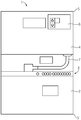
- FIG. 1 shows a schematic representation of an electrical protection arrangement comprising a residual current device and a circuit breaker.
- the electrical protection arrangement 1 shown schematically in the figure here comprises a residual current protection device 2, which can also be referred to as RCD (Residual Current Protective Device).
- the residual current device 2 may be a differential current device or a residual current device of the known type.
- the fault current protection device 2 as shown by way of example in the figure, a housing 3.
- the electrical protection arrangement 1 comprises a circuit breaker 4 which is arranged in a separate housing 5.
- the housing 3 of the residual current device 2 and the housing 5 of the Circuit breaker 4 can be positively connected with each other.
- the residual current device 2 and the power switch 4 are housed in cabinets where they are connected to the corresponding bus bars.
- the circuit breaker 4 can also be referred to as a main switch and is used for switching currents and voltages, as they are possible for example in production plants, residential buildings and the like.
- the circuit breaker 4 usually includes an electrical detection device, not shown here, which may also be referred to as ETU (Electronic Trip Unit).
- the electrical detection device may comprise a current transformer with which voltages and electrical currents in the electrical lines can be detected. From the voltages and / or the currents can be determined whether an overcurrent or a short circuit exists.
- the circuit breaker 4 comprises a triggering device 6, which is shown only schematically in the present case. With the tripping device 6, a switching device of the circuit breaker 4 can be triggered if an overcurrent and / or a short circuit has been detected with the electrical detection device.
- the fault current protection device 2 here comprises a detection device, not shown, which is able to detect a fault current or a differential current in the electrical installation or in the network.
- the detection device is, for example, a residual current device or a residual current device.
- the detection device comprises a summation current transformer whose output signal is different from zero when a fault current or a differential current is present.
- the output signal of the summation current transformer is supplied to a computing unit of the residual current device 2, with which the output signal is compared with a threshold value becomes. If the threshold is exceeded, a corresponding trigger signal is output.
- the residual current device 2 or its evaluation device is electrically connected via a cable 7 to the tripping device 6 of the circuit breaker 4. Via the cable 7, the trigger signal from the residual current device 2 can be transmitted to the tripping device 6 of the circuit breaker 4.
- the tripping device 6 of the circuit breaker 4 receives the tripping signal from the residual current device 2, the circuit breaker 4 or a switching device of the circuit breaker 4 is triggered. As a result, the electronics installation or the network is switched off.
- the cable 7 is formed as a data bus and the fault current protection device 2 and the evaluation of which transmits the trigger signal in digital form to the tripping device 6 of the circuit breaker 4.
- the cable 7 or the associated electrical contact elements on the triggering device and on the residual current device may be designed polarity reversal.
- a corresponding inscription can be provided on the cable 7, which marks the correct connection of the cable 7 to the residual current device 2 and to the tripping device 6.
- the residual current device 2 and / or the circuit breaker 4 comprise a monitoring unit with which it can be detected that the cable 7 is connected on the one hand to the residual current device 2 and on the other hand to the circuit breaker 4 or the tripping device 6. For example, if the cable 7 is not properly connected to the residual current device 2 or the circuit breaker 4, a warning signal may be output. This can be done for example on a display unit 8 of the residual current device 2. At the Display unit 8, which comprises a plurality of lighting elements, for example, a corresponding signal can be output, if the fault current protection device 2, a fault current is detected.
- the residual current device 2 uses the tripping device 6 of the circuit breaker 4, it requires no additional triggering device for the residual current device 2. Thus, costs can be saved.
- accessory bags which may be arranged for example in the housing 5 of the circuit breaker 4.
- the customer of the electrical protection arrangement 1 further accessory components can be integrated into the accessory bags.
Landscapes
- Emergency Protection Circuit Devices (AREA)
Description
- Die vorliegende Erfindung betrifft eine elektrische Schutzanordnung für eine Elektroinstallation mit einer Fehlerstromschutzvorrichtung, die eine Detektionseinrichtung zum Erfassen eines Fehlerstroms und eine Auswerteeinrichtung zum Vergleichen des erfassten Fehlerstroms mit einem Schwellenwert sowie zum Ausgeben eines Auslösesignals, falls der erfasste Fehlerstrom den Schwellenwert überschreitet, aufweist und einen Leistungsschalter, der eine elektrische Erfassungseinrichtung zum Erfassen eines Überstroms und/oder eines Kurzschlusses sowie eine Auslöseeinrichtung zum Auslösen einer Schalteinrichtung, falls die elektrische Erfassungseinrichtung einen Überstrom und/oder einen Kurzschluss erfasst, aufweist. Darüber hinaus betrifft die vorliegende Erfindung ein Verfahren zum Betreiben einer elektrischen Schutzanordnung für eine Elektroinstallation.
- Derartige elektrische Schutzanordnungen können beispielsweise in Gebäuden oder in Industrieanlagen verwendet werden. Diese elektrischen Schutzanordnungen können eine Fehlerstromschutzvorrichtung und einen Leistungsschalter umfassen. Fehlerstromschutzvorrichtungen, die beispielsweise als Differenzstromgeräte oder Fehlerstromgeräte ausgebildet sind, bieten in Niederspannungsnetzen einen Fehlerschutz für den Fall, dass die Basisisolierung versagt oder spannungsführende Teile direkt berührt werden. Dadurch werden Schädigungen an Menschen, Sachwerten und Nutztieren verhindert oder reduziert.
- Fehlerstromschutzvorrichtungen können an übliche Leistungsschalter angebaut oder als externe, modulare Lösung realisiert werden. Alternativ können die Fehlerstromschutzvorrichtungen auch in Kompaktleistungsschalter integriert sein. Tritt im Betrieb einer Anlage dann ein Fehlerstrom auf, wird dieser durch die Fehlerstromschutzvorrichtung detektiert, und sie löst den zuständigen (Kompakt-) Leistungsschalter aus und schaltet somit die Anlage spannungsfrei.
- Bei speziellen Arten von Fehlerstromschutzvorrichtungen sind als Auslöseeinrichtung sogenannte Hilfsauslöser vorgesehen. Diese Hilfsauslöser sind elektromechanische Systeme, insbesondere auf Magnetbasis, mit denen aus einem Ansteuersignal in Folge eines Fehlerstroms eine Bewegung, insbesondere für ein Schaltschloss, erzeugt werden kann. Im speziellen Fall kann ein Hilfsauslöser auch als Auslösemagnet bezeichnet werden. Je nach Funktion unterscheidet man bei den Hilfsauslösern zwischen Spannungsauslösern und Unterspannungsauslösern. Spannungsauslöser lösen aus (d.h. erzeugen eine mechanische Bewegung), wenn eine Spannungsschwelle überschritten wird. Unterspannungsauslöser lösen aus, wenn eine Spannungsschwelle unterschritten wird.
- Die Fehlerstromschutzvorrichtung und der Leistungsschalter sind üblicherweise in separaten Gehäusen angeordnet. Der Leistungsschalter kann ein Gehäuse besitzen, in dem eine oder mehrere Zubehörtaschen vorgesehen sind. In eine solche Zubehörtasche kann der oben erwähnte Hilfsauslöser, ein Hilfsschalter, ein Alarmschalter oder dergleichen eingesteckt werden. Mit diesem modularen Zubehör ist also eine elektrische Schutzanordnung, die einen Leistungsschalter und eine Fehlerstromschutzvorrichtung umfassen kann, individualisierbar.
- Bei den bisherigen Lösungen löst die Fehlerstromschutzvorrichtung bzw. das Differenzstromgerät im Falle eines Fehlerstroms entweder über einen Auslösemagnet (mit Hilfe eines Stößels), der in dem Differenzstromgerät integriert ist, oder über einen separaten Auslösemagneten (Spannungsauslöser), der in die Zubehörtasche des Kompaktleistungsschalters eingebaut wird, den Kompaktleistungsschalter aus.
- Hierzu beschreibt die
US 2003/0189804 A1 eine elektrische Schutzanordnung für eine Elektroinstallation, welche Sensoren zum Erfassen eines Fehlerstroms aufweist. Zudem sind Mittel vorgesehen, welche Schalter auslösen, falls der Fehlerstrom einen Schwellenwert überschreitet. Ferner ist ein Detektor zum Erkennen eines Überstroms vorgesehen. Falls ein Überstrom erkannt wird, können ebenfalls die Schalter ausgelöst werden. - Ferner zeigt die
WO 2008/112901 A2 eine elektrische Anordnung zum Schutz vor Überstrom und Fehlerströmen. Die elektrische Anordnung umfasst eine Fehlerstromschutzvorrichtung und einen Leistungsschalter. Dabei ist es vorgesehen, dass die Fehlerstromschutzvorrichtung ein Auslösesignal an eine Auslöseeinrichtung des Leistungsschalters abgeben kann. - Es ist Aufgabe der vorliegenden Erfindung, eine elektrische Schutzanordnung, die eine Fehlerstromschutzvorrichtung und einen Leistungsschalter umfasst, bereitzustellen, die kostengünstiger und bauraumsparender ausgebildet ist.
- Diese Aufgabe wird durch eine elektrische Schutzanordnung mit den Merkmalen des Patentanspruchs 1 sowie durch ein Verfahren mit den Merkmalen des Patentanspruchs 6 gelöst. Vorteilhafte Weiterbildungen der vorliegenden Erfindung sind Gegenstand der abhängigen Ansprüche.
- Die erfindungsgemäße elektrische Schutzanordnung für eine Elektroinstallation umfasst eine Fehlerstromschutzvorrichtung, die eine Detektionseinrichtung zum Erfassen eines Fehlerstroms und eine Auswerteeinrichtung zum Vergleichen des erfassten Fehlerstroms mit einem Schwellenwert sowie zum Ausgeben eines Auslösesignals, falls der erfasste Fehlerstrom den Schwellenwert überschreitet, aufweist und einen Leistungsschalter, der eine elektrische Erfassungseinrichtung zum Erfassen eines Überstroms und/oder eines Kurzschlusses sowie eine Auslöseeinrichtung zum Auslösen einer Schalteinrichtung, falls die elektrische Erfassungseinrichtung einen Überstrom und/oder einen Kurzschluss erfasst, aufweist, wobei die Fehlerstromschutzvorrichtung dazu ausgebildet ist, das Auslösesignal an die Auslöseeinrichtung des Leistungsschalters zu übertragen, in Folge dessen diese die Schalteinrichtung auslöst.
- Die elektrische Schutzanordnung umfasst eine Fehlerstromschutzvorrichtung und einen Leistungsschalter. Die Fehlerstromschutzvorrichtung umfasst wiederum eine Detektionseinrichtung mit der ein Fehlerstrom erfasst werden kann. Diese Detektionseinrichtung kann beispielsweise als Summenstromwandler ausgebildet sein. Darüber hinaus umfasst die Fehlerstromschutzvorrichtung eine Auswerteeinrichtung, also eine entsprechende Auswerteelektronik, die den erfassten Fehlerstrom mit einem Schwellenwert vergleichen kann. Falls der erfasste Fehlerstrom den vorbestimmten Schwellenwert überschreitet, wird ein Auslösesignal mittels der Auswerteeinrichtung ausgegeben. Der Leistungsschalter umfasst eine elektrische Erfassungseinrichtung, die auch als Electronic Trip Unit (ETU) bezeichnet werden kann. Diese elektrische Erfassungseinrichtung kann einen entsprechenden Stromwandler umfassen, mit dem die elektrischen Spannungen und die elektrischen Stromstärken in den Leitungen der Elektroinstallation überwacht werden können. Des Weiteren umfasst der Leistungsschalter eine Auslöseeinrichtung, die für den Fall, dass mit der elektrischen Erfassungseinrichtung ein Überstrom und/oder ein Kurzschluss erfasst werden, eine Schalteinrichtung bzw. ein Schaltschloss auslöst. In Folge dessen werden die elektrischen Leitungen der Elektroninstallation galvanisch getrennt.
- Gemäß der vorliegenden Erfindung ist die Fehlerstromschutzvorrichtung dazu ausgebildet, das Auslösesignal, das von der Auswerteeinrichtung der Fehlerstromschutzvorrichtung im Falle eines Fehlerstroms bereitgestellt wird, an die Auslöseeinrichtung des Leistungsschalters zu übertragen. Wenn das Auslösesignal an die Auslöseeinrichtung des Leistungsschalters übertragen wird, wird die mit der Auslöseeinrichtung verbundene Schalteinrichtung ausgelöst. Damit kann die Elektroninstallation spannungsfrei geschaltet werden. Somit bedarf es keines zusätzlichen Auslösemagneten, der in die Fehlerstromschutzvorrichtung integriert werden muss. Auf diese Weise kann eine bauraumsparende elektrische Schutzanordnung bereitgestellt werden. Überdies können Kosten eingespart werden, da für die Fehlerstromschutzvorrichtung eine eigene Auslöseeinrichtung bereitgestellt werden muss.
- Zudem ist die Fehlerstromschutzvorrichtung mit der Auslöseeinrichtung des Leistungsschalters mittels eines Kabels elektrisch verbunden. Auf diese Weise kann das Auslösesignal, das von der Fehlerstromschutzvorrichtung bereitgestellt wird, auf einfache Weise an die Auslöseeinrichtung des Leistungsschalters übertragen werden. Durch das Kabel werden keine Einschränkungen vorgegeben, wie die Fehlerstromschutzvorrichtung zu dem Leistungsschalter angeordnet werden kann. Somit kann eine flexible und einfache Lösung bei dem Aufbau einer elektrischen Schutzanordnung bereitgestellt werden.
- Ferner weisen die Fehlerstromschutzvorrichtung ein erstes elektrisches Kontaktelement zum Anschließen des Kabels und die Auslöseeinrichtung ein vom ersten elektrischen Kontaktelement verschiedenes zweites elektrisches Kontaktelement zum Anschließen des Kabels auf. Mit anderen Worten weisen die Fehlerstromschutzvorrichtung und die Auslöseeinrichtung zwei unterschiedliche Kontaktelemente auf, die entweder als Stecker oder als Buchse ausgebildet sein können. Zudem kann das Kabel entsprechende Anschlusselemente aufweisen, die zu den jeweiligen elektrischen Kontaktelementen passend ausgebildet sind. Somit kann eine elektrische Verbindung zwischen der Fehlerstromschutzvorrichtung und der Auslöseeinrichtung mit einem Verpolungsschutz bereitgestellt werden. Darüber hinaus ist es denkbar, dass das Kabel entsprechend beschriftet ist.
- Des Weiteren weist die Fehlerstromschutzvorrichtung und/oder die Auslöseeinrichtung eine Überwachungseinheit zum Überwachen einer elektrischen Verbindung zwischen dem ersten Kontaktelement und dem Kabel und/oder einer elektrischen Verbindung zwischen dem zweiten Kontaktelement und dem Kabel auf. Somit kann mittels einer Überwachungseinheit, die entweder in der Fehlerstromschutzvorrichtung, der Auslöseeinrichtung oder sowohl in der Fehlerstromschutzvorrichtung als auch in der Auslöseeinrichtung angeordnet ist, auf einfache Weise festgestellt werden, ob die Fehlerstromschutzvorrichtung zum Übertragen des Auslösesignals mittels der Auslöseeinrichtung des Leistungsschalters verbunden ist. Falls die Datenverbindung zwischen der Fehlerstromschutzvorrichtung und der Auslöseeinrichtung nicht besteht, kann beispielsweise ein entsprechendes Warnsignal ausgegeben werden. Somit kann ein sicherer Betrieb der elektrischen Schutzanordnung garantiert werden.
- In einer weiteren Ausgestaltung ist das Kabel als Datenbus ausgebildet. Hierbei ist es auch denkbar, dass die Fehlerstromschutzvorrichtung bzw. die Auswerteeinrichtung der Fehlerstromschutzvorrichtung dazu ausgebildet ist, das Auslösesignal in Form eines digitalen Signals, das über einen Datenbus übertragen werden kann, bereitzustellen. Dies bietet zudem den Vorteil, dass das Auslösesignal in der digitalen Form beispielsweise einem Kommunikationssystem bereitgestellt werden kann.
- Bevorzugt sind die Fehlerstromschutzvorrichtung und der Leistungsschalter jeweils in einem separaten Gehäuse angeordnet. Auf diese Weise können die Fehlerstromschutzvorrichtung und der Leistungsschalter, beispielsweise in einem Schaltschrank, beliebig zueinander positioniert werden. Auf diese Weise wird eine modulare Lösung für eine elektrische Schutzanordnung bereitgestellt.
- Bevorzugt sind das Gehäuse der Fehlerstromschutzvorrichtung und das Gehäuse des Leistungsschalters formschlüssig miteinander verbindbar. Beispielsweise können die beiden Gehäuse durch Steckverbindungen oder dergleichen verbunden werden. Auf diese Weise können die Fehlerstromschutzvorrichtung der Leistungsschalter einfach kombiniert werden.
- In einer weiteren Ausführungsform ist die Auslöseeinrichtung als Spannungsauslöser ausgebildet. Alternativ dazu kann die Auslöseeinrichtung als Unterspannungsauslöser ausgebildet sein. Auf diese Weise kann ein sicherer Betrieb der elektrischen Schutzanordnung garantiert werden.
- Das erfindungsgemäße Verfahren zum Betreiben einer elektrischen Schutzanordnung für eine Elektroninstallation umfasst das Erfassen eines Fehlerstroms mit einer Detektionseinrichtung einer Fehlerstromschutzvorrichtung, das Vergleichen des erfassten Fehlerstroms mit einem Schwellenwert mit einer Auswerteeinrichtung der Fehlerstromschutzvorrichtung, das Ausgeben eines Auslösesignals, falls der erfasste Fehlerstrom den Schwellenwert überschreitet mit der Auswerteeinrichtung, das Erfassen eines Überstroms und/oder eines Kurzschlusses mit einer elektrischen Erfassungseinrichtung eines Leistungsschalters und das Auslösen einer Schalteinrichtung, falls mit der elektrischen Erfassungseinrichtung ein Überstrom und/oder ein Kurzschluss erfasst wird, mit der Auslöseeinrichtung, wobei das Auslösesignal von der Fehlerstromschutzvorrichtung an die Auslöseeinrichtung des Leistungsschalters übertragen wird, in Folge dessen die Schalteinrichtung ausgelöst wird, wobei die Fehlerstromschutzvorrichtung mit der Auslöseeinrichtung des Leistungsschalters mittels eines Kabels elektrisch verbunden ist. Des Weiteren weisen die Fehlerstromschutzvorrichtung ein erstes elektrisches Kontaktelement zum Anschließen des Kabels und die Auslöseeinrichtung ein vom ersten elektrischen Kontaktelement verschiedenes zweites elektrisches Kontaktelement zum Anschließen des Kabels auf. Zudem wird eine elektrische Verbindung zwischen dem ersten Kontaktelement und dem Kabel und/oder eine elektrische Verbindung zwischen dem zweiten Kontaktelement und dem Kabel mit einer Überwachungseinheit der Fehlerstromschutzvorrichtung und/oder der Auslöseeinrichtung überwacht.
- Die zuvor im Zusammenhang mit der erfindungsgemäßen elektrischen Schutzanordnung beschriebenen Vorteile und Weiterbildungen gelten sinngemäß für das erfindungsgemäße Verfahren.
- Die vorliegende Erfindung wird nun anhand der beigefügten Zeichnung näher erläutert. Dabei zeigt die Figur eine schematische Darstellung einer elektrischen Schutzanordnung, die eine Fehlerstromschutzvorrichtung und einen Leistungsschalter umfasst.
- Das nachfolgend näher geschilderte Ausführungsbeispiel stellt eine bevorzugte Ausführungsform der vorliegenden Erfindung dar.
- Die vorliegend in der Figur schematisch dargestellte elektrische Schutzanordnung 1 umfasst eine Fehlerstromschutzvorrichtung 2, die auch als RCD (Residual Current Protective Device) bezeichnet werden kann. Die Fehlerstromschutzvorrichtung 2 kann ein Differenzstromgerät bzw. ein Fehlerstromschutzgerät der bekannten Bauart sein. Dabei weist die Fehlerstromschutzvorrichtung 2, wie sie exemplarisch in der Figur dargestellt ist, ein Gehäuse 3 auf. Darüber hinaus umfasst die elektrische Schutzanordnung 1 einen Leistungsschalter 4 der in einem separaten Gehäuse 5 angeordnet ist. Das Gehäuse 3 der Fehlerstromschutzvorrichtung 2 und das Gehäuse 5 des Leistungsschalters 4 können formschlüssig miteinander verbunden werden. Typischerweise sind die Fehlerstromschutzvorrichtung 2 und der Leistungsschalter 4 in Schaltschränken untergebracht, wo sie an die entsprechenden Stromschienen angeschlossen sind.
- Der Leistungsschalter 4 kann auch als Hauptschalter bezeichnet werden und dient zum Schalten von Strömen und Spannungen, wie sie beispielsweise in Produktionsanlagen, Wohngebäuden und dergleichen möglich sind. Der Leistungsschalter 4 umfasst üblicherweise eine hier nicht näher dargestellte elektrische Erfassungseinrichtung, die auch als ETU (Electronic Trip Unit) bezeichnet werden kann. Die elektrische Erfassungseinrichtung kann einen Stromwandler umfassen, mit dem Spannungen und elektrische Stromstärken in den elektrischen Leitungen erfasst werden können. Aus den Spannungen und/oder den Stromstärken kann ermittelt werden, ob ein Überstrom oder ein Kurzschluss vorliegt. Darüber hinaus umfasst der Leistungsschalter 4 eine Auslöseeinrichtung 6, die vorliegend nur schematisch dargestellt ist. Mit der Auslöseeinrichtung 6 kann eine Schalteinrichtung des Leistungsschalters 4 ausgelöst werden, falls mit der elektrischen Erfassungseinrichtung ein Überstrom und/oder ein Kurzschluss erfasst worden ist.
- Die Fehlerstromschutzvorrichtung 2 umfasst hier eine nicht dargestellte Detektionseinrichtung, die in der Lage ist, einen Fehlerstrom oder einen Differenzstrom in der Elektroinstallation bzw. in dem Netz zu detektieren. Bei der Detektionseinrichtung handelt es sich beispielsweise um ein Differenzstromschutzgerät oder ein Fehlerstromschutzgerät. Die Detektionseinrichtung umfasst einen Summenstromwandler, dessen Ausgangssignal von null verschieden ist, wenn ein Fehlerstrom oder ein Differenzstrom vorliegt. Das Ausgangssignal des Summenstromwandlers wird einer Recheneinheit der Fehlerstromschutzvorrichtung 2 zugeführt, mit der das Ausgangssignal mit einem Schwellenwert verglichen wird. Falls der Schwellenwert überschritten wird, wird ein entsprechendes Auslösesignal ausgegeben.
- Vorliegend ist die Fehlerstromschutzvorrichtung 2 bzw. deren Auswerteeinrichtung über ein Kabel 7 mit der Auslöseeinrichtung 6 des Leistungsschalters 4 elektrisch verbunden. Über das Kabel 7 kann das Auslösesignal von der Fehlerstromschutzvorrichtung 2 zu der Auslöseeinrichtung 6 des Leistungsschalters 4 übertragen werden. Wenn die Auslöseeinrichtung 6 des Leistungsschalters 4 das Auslösesignal von der Fehlerstromschutzvorrichtung 2 empfängt, wird der Leistungsschalter 4 bzw. eine Schalteinrichtung des Leistungsschalters 4 ausgelöst. Dadurch wird die Elektroninstallation bzw. das Netz spannungsfrei geschaltet.
- Dabei ist es auch denkbar, dass das Kabel 7 als Datenbus ausgebildet ist und die Fehlerstromschutzvorrichtung 2 bzw. deren Auswerteeinrichtung das Auslösesignal in digitaler Form an die Auslöseeinrichtung 6 des Leistungsschalters 4 überträgt. Das Kabel 7 bzw. die dazugehörigen elektrischen Kontaktelemente an der Auslöseeinrichtung und an der Fehlerstromschutzvorrichtung können verpolsicher ausgebildet sein. Darüber hinaus kann auf dem Kabel 7 eine entsprechende Beschriftung vorgesehen sein, die den richtigen Anschluss des Kabels 7 an der Fehlerstromschutzvorrichtung 2 und an der Auslöseeinrichtung 6 kennzeichnet.
- Die Fehlerstromschutzvorrichtung 2 und/oder der Leistungsschalter 4 umfassen eine Überwachungseinheit, mit der erfasst werden kann, dass das Kabel 7 einerseits mit der Fehlerstromschutzvorrichtung 2 und andererseits mit dem Leistungsschalter 4 bzw. der Auslöseeinrichtung 6 verbunden ist. Wenn das Kabel 7 beispielsweise nicht korrekt mit der Fehlerstromschutzvorrichtung 2 oder dem Leistungsschalter 4 verbunden ist, kann ein Warnsignal ausgegeben werden. Dies kann beispielsweise an einer Anzeigeeinheit 8 der Fehlerstromschutzvorrichtung 2 erfolgen. An der Anzeigeeinheit 8, die mehrere Leuchtelemente umfasst, kann beispielsweise auch ein entsprechendes Signal ausgegeben werden, falls mit der Fehlerstromschutzvorrichtung 2 ein Fehlerstrom erfasst wird.
- Dadurch, dass die Fehlerstromschutzvorrichtung 2 die Auslöseeinrichtung 6 des Leistungsschalters 4 nutzt, bedarf es keiner zusätzlichen Auslöseeinrichtung für die Fehlerstromschutzvorrichtung 2. Damit können Kosten eingespart werden. Darüber hinaus besteht keine Belegung von Zubehörtaschen, die beispielsweise in dem Gehäuse 5 des Leistungsschalters 4 angeordnet sein können. Somit können von dem Kunden der elektrischen Schutzanordnung 1 weitere Zubehörkomponenten in die Zubehörtaschen integriert werden.
Claims (6)
- Elektrische Schutzanordnung (1) für eine Elektroinstallation mit- einer Fehlerstromschutzvorrichtung (2), die eine Detektionseinrichtung zum Erfassen eines Fehlerstroms und eine Auswerteeinrichtung zum Vergleichen des erfassten Fehlerstroms mit einem Schwellenwert sowie zum Ausgeben eines Auslösesignals, falls der erfasste Fehlerstrom den Schwellenwert überschreitet, aufweist und- einem Leistungsschalter (4), der eine elektrische Erfassungseinrichtung zum Erfassen eines Überstroms und/oder eines Kurzschlusses sowie eine Auslöseeinrichtung (6) zum Auslösen einer Schalteinrichtung, falls die elektrische Erfassungseinrichtung einen Überstrom und/oder einen Kurzschluss erfasst, aufweist, wobei- die Fehlerstromschutzvorrichtung (2) dazu ausgebildet ist, das Auslösesignal an die Auslöseeinrichtung des Leistungsschalters (4) zu übertragen, in Folge dessen diese die Schalteinrichtung auslöst und wobei- die Fehlerstromschutzvorrichtung (2) mit der Auslöseeinrichtung (6) des Leistungsschalters (4) mittels eines Kabels (7) elektrisch verbunden ist,dadurch gekennzeichnet, dass- die Fehlerstromschutzvorrichtung (2) ein erstes elektrisches Kontaktelement zum Anschließen des Kabels (7) und die Auslöseeinrichtung (6) ein vom ersten elektrischen Kontaktelement verschiedenes zweites elektrisches Kontaktelement zum Anschließen des Kabels (7) aufweisen und- die Fehlerstromschutzvorrichtung (2) und/oder die Auslöseeinrichtung (6) eine Überwachungseinheit zum Überwachen einer elektrischen Verbindung zwischen dem ersten Kontaktelement und dem Kabel (7) und/oder einer elektrischen Verbindung zwischen dem zweiten Kontaktelement und dem Kabel (7) aufweist.
- Elektrische Schutzanordnung (1) nach Anspruch 1, wobei das Kabel (7) als Datenbus ausgebildet ist.
- Elektrische Schutzanordnung (1) nach einem der vorhergehenden Ansprüche, wobei die Fehlerstromschutzvorrichtung (2) und der Leistungsschalter (4) jeweils in einem separaten Gehäuse (3, 5) angeordnet sind.
- Elektrische Schutzanordnung (1) nach Anspruch 3, wobei das Gehäuse (3) der Fehlerstromschutzvorrichtung (2) und das Gehäuse (5) des Leistungsschalters (4) formschlüssig miteinander verbindbar sind.
- Elektrische Schutzanordnung (1) nach einem der vorhergehenden Ansprüche, wobei die Auslöseeinrichtung (6) als Spannungsauslöser ausgebildet ist.
- Verfahren zum Betreiben einer elektrischen Schutzanordnung (1) für eine Elektroinstallation durch- Erfassen eines Fehlerstroms mit einer Detektionseinrichtung einer Fehlerstromschutzvorrichtung (2),- Vergleichen des erfassten Fehlerstroms mit einem Schwellenwert mit einer Auswerteeinrichtung der Fehlerstromschutzvorrichtung,- Ausgeben eines Auslösesignals, falls der erfasste Fehlerstrom den Schwellenwert überschreitet, mit der Auswerteeinrichtung,- Erfassen eines Überstroms und/oder eines Kurzschlusses mit einer elektrischen Erfassungseinrichtung eines Leistungsschalter (4) und- Auslösen einer Schalteinrichtung, falls mit der elektrischen Erfassungseinrichtung ein Überstrom und/oder ein Kurzschluss erfasst wird, mit der Auslöseeinrichtung (6), wobei- das Auslösesignal von der Fehlerstromschutzvorrichtung (2) an die Auslöseeinrichtung (6) des Leistungsschalters übertragen wird, in Folge dessen die Schalteinrichtung auslöst wird, wobei die Fehlerstromschutzvorrichtung (2) mit der Auslöseeinrichtung (6) des Leistungsschalters (4) mittels eines Kabels (7) elektrisch verbunden ist,dadurch gekennzeichnet, dass- die Fehlerstromschutzvorrichtung (2) ein erstes elektrisches Kontaktelement zum Anschließen des Kabels (7) und die Auslöseeinrichtung (6) ein vom ersten elektrischen Kontaktelement verschiedenes zweites elektrisches Kontaktelement zum Anschließen des Kabels (7) aufweisen und- eine elektrische Verbindung zwischen dem ersten Kontaktelement und dem Kabel (7) und/oder eine elektrische Verbindung zwischen dem zweiten Kontaktelement und dem Kabel (7) mit einer Überwachungseinheit der Fehlerstromschutzvorrichtung (2) und/oder der Auslöseeinrichtung (6) überwacht wird.
Applications Claiming Priority (1)
| Application Number | Priority Date | Filing Date | Title |
|---|---|---|---|
| DE102014201503.0A DE102014201503A1 (de) | 2014-01-28 | 2014-01-28 | Elektrische Schutzanordnung für eine Elektroinstallation sowie dazugehöriges Verfahren |
Publications (2)
| Publication Number | Publication Date |
|---|---|
| EP2899823A1 EP2899823A1 (de) | 2015-07-29 |
| EP2899823B1 true EP2899823B1 (de) | 2018-06-13 |
Family
ID=51900774
Family Applications (1)
| Application Number | Title | Priority Date | Filing Date |
|---|---|---|---|
| EP14193267.3A Active EP2899823B1 (de) | 2014-01-28 | 2014-11-14 | Elektrische Schutzanordnung für eine Elektroinstallation sowie dazugehöriges Verfahren |
Country Status (3)
| Country | Link |
|---|---|
| EP (1) | EP2899823B1 (de) |
| CN (1) | CN104810784B (de) |
| DE (1) | DE102014201503A1 (de) |
Families Citing this family (3)
| Publication number | Priority date | Publication date | Assignee | Title |
|---|---|---|---|---|
| DE102016218242A1 (de) | 2016-09-22 | 2018-03-22 | Siemens Aktiengesellschaft | DC-Überspannungsschutz für ein Energiesystem |
| KR102535555B1 (ko) | 2017-04-07 | 2023-05-23 | 주식회사 다이셀 | 표면 수식 나노 다이아몬드, 표면 수식 나노 다이아몬드 분산액, 및 수지 분산체 |
| DE102022208081A1 (de) | 2022-08-03 | 2024-02-08 | Siemens Aktiengesellschaft | Leistungsschalter |
Citations (1)
| Publication number | Priority date | Publication date | Assignee | Title |
|---|---|---|---|---|
| WO2008112901A2 (en) | 2007-03-13 | 2008-09-18 | Carling Technologies, Inc. | Circuit breakers with ground fault and overcurrent trip |
Family Cites Families (5)
| Publication number | Priority date | Publication date | Assignee | Title |
|---|---|---|---|---|
| US5652420A (en) * | 1995-11-14 | 1997-07-29 | Eaton Corporation | Modular contactor control system |
| US6804094B2 (en) * | 2002-04-04 | 2004-10-12 | Power Electronic Systems, Inc. | Ground fault circuit interrupter |
| CN201219092Y (zh) * | 2008-06-02 | 2009-04-08 | 比亚迪股份有限公司 | 一种接地故障断路器 |
| CN101900771B (zh) * | 2009-05-31 | 2013-11-27 | 西门子公司 | Rcd检测装置和检测方法 |
| EP2587513A1 (de) * | 2011-10-26 | 2013-05-01 | ABB Schweiz AG | Installationsschaltgerät mit einer Stromsensoreinheit |
-
2014
- 2014-01-28 DE DE102014201503.0A patent/DE102014201503A1/de not_active Withdrawn
- 2014-11-14 EP EP14193267.3A patent/EP2899823B1/de active Active
-
2015
- 2015-01-28 CN CN201510042543.4A patent/CN104810784B/zh active Active
Patent Citations (1)
| Publication number | Priority date | Publication date | Assignee | Title |
|---|---|---|---|---|
| WO2008112901A2 (en) | 2007-03-13 | 2008-09-18 | Carling Technologies, Inc. | Circuit breakers with ground fault and overcurrent trip |
Non-Patent Citations (2)
| Title |
|---|
| "Feldleit- und Schutzgerät REF542 (SCU)", ABB HANDBUCH, July 1999 (1999-07-01), pages 574pp |
| "Medium voltage products, eVD4 Installations- und Betriebsanleitungen - 12...17,5 kV - 630...2000 A - 16...40 kA", February 2011 (2011-02-01), pages 2pp, 1 - 66, XP055575816 |
Also Published As
| Publication number | Publication date |
|---|---|
| EP2899823A1 (de) | 2015-07-29 |
| CN104810784A (zh) | 2015-07-29 |
| DE102014201503A1 (de) | 2015-07-30 |
| CN104810784B (zh) | 2019-06-07 |
Similar Documents
| Publication | Publication Date | Title |
|---|---|---|
| EP2020014B1 (de) | Schalteinrichtung | |
| DE102017125308B4 (de) | Schaltgerät mit Schnittstellenmodul | |
| EP3273459A1 (de) | Einrichtung und verfahren zur überwachung einer unterbrechungseinheit in einem elektrischen energieversorgungsnetz sowie verteilerstation mit einer überwachten unterbrechungseinheit | |
| EP2587513A1 (de) | Installationsschaltgerät mit einer Stromsensoreinheit | |
| EP4377984A1 (de) | Schutzschaltgerät und verfahren | |
| EP3086426A1 (de) | Brandschutzschalter | |
| EP0570603B1 (de) | Eigensicherer Differenzstromschutzschalter | |
| AT507025A1 (de) | Elektrische installationsanordnung | |
| EP2945240A1 (de) | Stromverteilervorrichtung mit schutzleiterüberwachungseinrichtung und verfahren | |
| DE102015000576A1 (de) | Kraftfahrzeug mit Schaltvorrichtung für eine bordnetzbetriebene Komponente | |
| EP2899823A1 (de) | Elektrische Schutzanordnung für eine Elektroinstallation sowie dazugehöriges Verfahren | |
| EP4367704A1 (de) | Schutzschaltgerät | |
| EP2899822B1 (de) | Elektrische Schutzanordnung für eine Elektroinstallation sowie dazugehöriges Verfahren | |
| EP1478069B1 (de) | Allstromsensitive Fehlerstrom-Schutzeinrichtung | |
| WO2014083188A1 (de) | Fehlerstromschutzschalter | |
| EP2899738B1 (de) | Externe Ansteuerung eines elektromagnetischen Auslösers | |
| DE102019103036B4 (de) | Ladesäule mit einem Kombi-Schaltmodul | |
| DE3813403C2 (de) | Ortsveränderlicher Differenzstromschalter | |
| WO2017005858A1 (de) | Fehlerstromsensor für eine fehlerstrom-schutzeinrichtung zum überwachen eines elektrischen verbrauchers für ein fahrzeug | |
| DE102020200993A1 (de) | Fernantrieb, Anordnung mit einem Fernantrieb sowie Verfahren | |
| DE10301905B4 (de) | Sicherungsschaltung | |
| EP1932400A1 (de) | Vorrichtung zur fehlerstromerkennung in einem elektronischen gerät | |
| EP2523304A1 (de) | Batterieladegerät und Verfahren hierfür | |
| EP3057118B1 (de) | Schaltmechanik, brandschutzschalter und system | |
| DE102023201130A1 (de) | Kompakt-Reiheneinbaugerät sowie mehrpoliges Reiheneinbaugerät |
Legal Events
| Date | Code | Title | Description |
|---|---|---|---|
| PUAI | Public reference made under article 153(3) epc to a published international application that has entered the european phase |
Free format text: ORIGINAL CODE: 0009012 |
|
| 17P | Request for examination filed |
Effective date: 20141114 |
|
| AK | Designated contracting states |
Kind code of ref document: A1 Designated state(s): AL AT BE BG CH CY CZ DE DK EE ES FI FR GB GR HR HU IE IS IT LI LT LU LV MC MK MT NL NO PL PT RO RS SE SI SK SM TR |
|
| AX | Request for extension of the european patent |
Extension state: BA ME |
|
| 17P | Request for examination filed |
Effective date: 20160126 |
|
| RBV | Designated contracting states (corrected) |
Designated state(s): AL AT BE BG CH CY CZ DE DK EE ES FI FR GB GR HR HU IE IS IT LI LT LU LV MC MK MT NL NO PL PT RO RS SE SI SK SM TR |
|
| RAP1 | Party data changed (applicant data changed or rights of an application transferred) |
Owner name: SIEMENS AKTIENGESELLSCHAFT |
|
| GRAP | Despatch of communication of intention to grant a patent |
Free format text: ORIGINAL CODE: EPIDOSNIGR1 |
|
| STAA | Information on the status of an ep patent application or granted ep patent |
Free format text: STATUS: GRANT OF PATENT IS INTENDED |
|
| INTG | Intention to grant announced |
Effective date: 20180202 |
|
| GRAS | Grant fee paid |
Free format text: ORIGINAL CODE: EPIDOSNIGR3 |
|
| GRAA | (expected) grant |
Free format text: ORIGINAL CODE: 0009210 |
|
| STAA | Information on the status of an ep patent application or granted ep patent |
Free format text: STATUS: THE PATENT HAS BEEN GRANTED |
|
| AK | Designated contracting states |
Kind code of ref document: B1 Designated state(s): AL AT BE BG CH CY CZ DE DK EE ES FI FR GB GR HR HU IE IS IT LI LT LU LV MC MK MT NL NO PL PT RO RS SE SI SK SM TR |
|
| REG | Reference to a national code |
Ref country code: GB Ref legal event code: FG4D Free format text: NOT ENGLISH |
|
| REG | Reference to a national code |
Ref country code: AT Ref legal event code: REF Ref document number: 1009460 Country of ref document: AT Kind code of ref document: T Effective date: 20180615 Ref country code: CH Ref legal event code: EP |
|
| REG | Reference to a national code |
Ref country code: IE Ref legal event code: FG4D Free format text: LANGUAGE OF EP DOCUMENT: GERMAN |
|
| REG | Reference to a national code |
Ref country code: DE Ref legal event code: R096 Ref document number: 502014008525 Country of ref document: DE |
|
| REG | Reference to a national code |
Ref country code: NL Ref legal event code: MP Effective date: 20180613 |
|
| REG | Reference to a national code |
Ref country code: LT Ref legal event code: MG4D |
|
| PG25 | Lapsed in a contracting state [announced via postgrant information from national office to epo] |
Ref country code: LT Free format text: LAPSE BECAUSE OF FAILURE TO SUBMIT A TRANSLATION OF THE DESCRIPTION OR TO PAY THE FEE WITHIN THE PRESCRIBED TIME-LIMIT Effective date: 20180613 Ref country code: ES Free format text: LAPSE BECAUSE OF FAILURE TO SUBMIT A TRANSLATION OF THE DESCRIPTION OR TO PAY THE FEE WITHIN THE PRESCRIBED TIME-LIMIT Effective date: 20180613 Ref country code: NO Free format text: LAPSE BECAUSE OF FAILURE TO SUBMIT A TRANSLATION OF THE DESCRIPTION OR TO PAY THE FEE WITHIN THE PRESCRIBED TIME-LIMIT Effective date: 20180913 Ref country code: BG Free format text: LAPSE BECAUSE OF FAILURE TO SUBMIT A TRANSLATION OF THE DESCRIPTION OR TO PAY THE FEE WITHIN THE PRESCRIBED TIME-LIMIT Effective date: 20180913 Ref country code: FI Free format text: LAPSE BECAUSE OF FAILURE TO SUBMIT A TRANSLATION OF THE DESCRIPTION OR TO PAY THE FEE WITHIN THE PRESCRIBED TIME-LIMIT Effective date: 20180613 Ref country code: CY Free format text: LAPSE BECAUSE OF FAILURE TO SUBMIT A TRANSLATION OF THE DESCRIPTION OR TO PAY THE FEE WITHIN THE PRESCRIBED TIME-LIMIT Effective date: 20180613 Ref country code: SE Free format text: LAPSE BECAUSE OF FAILURE TO SUBMIT A TRANSLATION OF THE DESCRIPTION OR TO PAY THE FEE WITHIN THE PRESCRIBED TIME-LIMIT Effective date: 20180613 |
|
| PG25 | Lapsed in a contracting state [announced via postgrant information from national office to epo] |
Ref country code: RS Free format text: LAPSE BECAUSE OF FAILURE TO SUBMIT A TRANSLATION OF THE DESCRIPTION OR TO PAY THE FEE WITHIN THE PRESCRIBED TIME-LIMIT Effective date: 20180613 Ref country code: LV Free format text: LAPSE BECAUSE OF FAILURE TO SUBMIT A TRANSLATION OF THE DESCRIPTION OR TO PAY THE FEE WITHIN THE PRESCRIBED TIME-LIMIT Effective date: 20180613 Ref country code: HR Free format text: LAPSE BECAUSE OF FAILURE TO SUBMIT A TRANSLATION OF THE DESCRIPTION OR TO PAY THE FEE WITHIN THE PRESCRIBED TIME-LIMIT Effective date: 20180613 Ref country code: GR Free format text: LAPSE BECAUSE OF FAILURE TO SUBMIT A TRANSLATION OF THE DESCRIPTION OR TO PAY THE FEE WITHIN THE PRESCRIBED TIME-LIMIT Effective date: 20180914 |
|
| PG25 | Lapsed in a contracting state [announced via postgrant information from national office to epo] |
Ref country code: NL Free format text: LAPSE BECAUSE OF FAILURE TO SUBMIT A TRANSLATION OF THE DESCRIPTION OR TO PAY THE FEE WITHIN THE PRESCRIBED TIME-LIMIT Effective date: 20180613 |
|
| PG25 | Lapsed in a contracting state [announced via postgrant information from national office to epo] |
Ref country code: SK Free format text: LAPSE BECAUSE OF FAILURE TO SUBMIT A TRANSLATION OF THE DESCRIPTION OR TO PAY THE FEE WITHIN THE PRESCRIBED TIME-LIMIT Effective date: 20180613 Ref country code: PL Free format text: LAPSE BECAUSE OF FAILURE TO SUBMIT A TRANSLATION OF THE DESCRIPTION OR TO PAY THE FEE WITHIN THE PRESCRIBED TIME-LIMIT Effective date: 20180613 Ref country code: IS Free format text: LAPSE BECAUSE OF FAILURE TO SUBMIT A TRANSLATION OF THE DESCRIPTION OR TO PAY THE FEE WITHIN THE PRESCRIBED TIME-LIMIT Effective date: 20181013 Ref country code: EE Free format text: LAPSE BECAUSE OF FAILURE TO SUBMIT A TRANSLATION OF THE DESCRIPTION OR TO PAY THE FEE WITHIN THE PRESCRIBED TIME-LIMIT Effective date: 20180613 Ref country code: CZ Free format text: LAPSE BECAUSE OF FAILURE TO SUBMIT A TRANSLATION OF THE DESCRIPTION OR TO PAY THE FEE WITHIN THE PRESCRIBED TIME-LIMIT Effective date: 20180613 Ref country code: RO Free format text: LAPSE BECAUSE OF FAILURE TO SUBMIT A TRANSLATION OF THE DESCRIPTION OR TO PAY THE FEE WITHIN THE PRESCRIBED TIME-LIMIT Effective date: 20180613 |
|
| PG25 | Lapsed in a contracting state [announced via postgrant information from national office to epo] |
Ref country code: SM Free format text: LAPSE BECAUSE OF FAILURE TO SUBMIT A TRANSLATION OF THE DESCRIPTION OR TO PAY THE FEE WITHIN THE PRESCRIBED TIME-LIMIT Effective date: 20180613 |
|
| REG | Reference to a national code |
Ref country code: DE Ref legal event code: R026 Ref document number: 502014008525 Country of ref document: DE |
|
| PLBI | Opposition filed |
Free format text: ORIGINAL CODE: 0009260 |
|
| PLAX | Notice of opposition and request to file observation + time limit sent |
Free format text: ORIGINAL CODE: EPIDOSNOBS2 |
|
| 26 | Opposition filed |
Opponent name: ABB SCHWEIZ AG Effective date: 20190313 |
|
| PG25 | Lapsed in a contracting state [announced via postgrant information from national office to epo] |
Ref country code: DK Free format text: LAPSE BECAUSE OF FAILURE TO SUBMIT A TRANSLATION OF THE DESCRIPTION OR TO PAY THE FEE WITHIN THE PRESCRIBED TIME-LIMIT Effective date: 20180613 Ref country code: SI Free format text: LAPSE BECAUSE OF FAILURE TO SUBMIT A TRANSLATION OF THE DESCRIPTION OR TO PAY THE FEE WITHIN THE PRESCRIBED TIME-LIMIT Effective date: 20180613 |
|
| REG | Reference to a national code |
Ref country code: CH Ref legal event code: PL |
|
| GBPC | Gb: european patent ceased through non-payment of renewal fee |
Effective date: 20181114 |
|
| PLBB | Reply of patent proprietor to notice(s) of opposition received |
Free format text: ORIGINAL CODE: EPIDOSNOBS3 |
|
| PG25 | Lapsed in a contracting state [announced via postgrant information from national office to epo] |
Ref country code: LU Free format text: LAPSE BECAUSE OF NON-PAYMENT OF DUE FEES Effective date: 20181114 Ref country code: MC Free format text: LAPSE BECAUSE OF FAILURE TO SUBMIT A TRANSLATION OF THE DESCRIPTION OR TO PAY THE FEE WITHIN THE PRESCRIBED TIME-LIMIT Effective date: 20180613 |
|
| REG | Reference to a national code |
Ref country code: BE Ref legal event code: MM Effective date: 20181130 |
|
| REG | Reference to a national code |
Ref country code: IE Ref legal event code: MM4A |
|
| PG25 | Lapsed in a contracting state [announced via postgrant information from national office to epo] |
Ref country code: CH Free format text: LAPSE BECAUSE OF NON-PAYMENT OF DUE FEES Effective date: 20181130 Ref country code: LI Free format text: LAPSE BECAUSE OF NON-PAYMENT OF DUE FEES Effective date: 20181130 |
|
| PG25 | Lapsed in a contracting state [announced via postgrant information from national office to epo] |
Ref country code: IE Free format text: LAPSE BECAUSE OF NON-PAYMENT OF DUE FEES Effective date: 20181114 |
|
| PG25 | Lapsed in a contracting state [announced via postgrant information from national office to epo] |
Ref country code: BE Free format text: LAPSE BECAUSE OF NON-PAYMENT OF DUE FEES Effective date: 20181130 Ref country code: AL Free format text: LAPSE BECAUSE OF FAILURE TO SUBMIT A TRANSLATION OF THE DESCRIPTION OR TO PAY THE FEE WITHIN THE PRESCRIBED TIME-LIMIT Effective date: 20180613 |
|
| PG25 | Lapsed in a contracting state [announced via postgrant information from national office to epo] |
Ref country code: GB Free format text: LAPSE BECAUSE OF NON-PAYMENT OF DUE FEES Effective date: 20181114 |
|
| PG25 | Lapsed in a contracting state [announced via postgrant information from national office to epo] |
Ref country code: MT Free format text: LAPSE BECAUSE OF FAILURE TO SUBMIT A TRANSLATION OF THE DESCRIPTION OR TO PAY THE FEE WITHIN THE PRESCRIBED TIME-LIMIT Effective date: 20180613 |
|
| PLAB | Opposition data, opponent's data or that of the opponent's representative modified |
Free format text: ORIGINAL CODE: 0009299OPPO |
|
| R26 | Opposition filed (corrected) |
Opponent name: ABB SCHWEIZ AG Effective date: 20190313 |
|
| PG25 | Lapsed in a contracting state [announced via postgrant information from national office to epo] |
Ref country code: TR Free format text: LAPSE BECAUSE OF FAILURE TO SUBMIT A TRANSLATION OF THE DESCRIPTION OR TO PAY THE FEE WITHIN THE PRESCRIBED TIME-LIMIT Effective date: 20180613 |
|
| PG25 | Lapsed in a contracting state [announced via postgrant information from national office to epo] |
Ref country code: PT Free format text: LAPSE BECAUSE OF FAILURE TO SUBMIT A TRANSLATION OF THE DESCRIPTION OR TO PAY THE FEE WITHIN THE PRESCRIBED TIME-LIMIT Effective date: 20180613 |
|
| PG25 | Lapsed in a contracting state [announced via postgrant information from national office to epo] |
Ref country code: HU Free format text: LAPSE BECAUSE OF FAILURE TO SUBMIT A TRANSLATION OF THE DESCRIPTION OR TO PAY THE FEE WITHIN THE PRESCRIBED TIME-LIMIT; INVALID AB INITIO Effective date: 20141114 Ref country code: MK Free format text: LAPSE BECAUSE OF NON-PAYMENT OF DUE FEES Effective date: 20180613 |
|
| REG | Reference to a national code |
Ref country code: AT Ref legal event code: MM01 Ref document number: 1009460 Country of ref document: AT Kind code of ref document: T Effective date: 20191114 |
|
| PG25 | Lapsed in a contracting state [announced via postgrant information from national office to epo] |
Ref country code: AT Free format text: LAPSE BECAUSE OF NON-PAYMENT OF DUE FEES Effective date: 20191114 |
|
| PLAB | Opposition data, opponent's data or that of the opponent's representative modified |
Free format text: ORIGINAL CODE: 0009299OPPO |
|
| R26 | Opposition filed (corrected) |
Opponent name: ABB SCHWEIZ AG Effective date: 20190313 |
|
| APAH | Appeal reference modified |
Free format text: ORIGINAL CODE: EPIDOSCREFNO |
|
| APBM | Appeal reference recorded |
Free format text: ORIGINAL CODE: EPIDOSNREFNO |
|
| P01 | Opt-out of the competence of the unified patent court (upc) registered |
Effective date: 20230512 |
|
| PGFP | Annual fee paid to national office [announced via postgrant information from national office to epo] |
Ref country code: DE Payment date: 20250714 Year of fee payment: 12 |
|
| PGFP | Annual fee paid to national office [announced via postgrant information from national office to epo] |
Ref country code: IT Payment date: 20251125 Year of fee payment: 12 |
|
| PGFP | Annual fee paid to national office [announced via postgrant information from national office to epo] |
Ref country code: FR Payment date: 20251114 Year of fee payment: 12 |