EP2899732A2 - Electromagnetic relay - Google Patents
Electromagnetic relay Download PDFInfo
- Publication number
- EP2899732A2 EP2899732A2 EP14190082.9A EP14190082A EP2899732A2 EP 2899732 A2 EP2899732 A2 EP 2899732A2 EP 14190082 A EP14190082 A EP 14190082A EP 2899732 A2 EP2899732 A2 EP 2899732A2
- Authority
- EP
- European Patent Office
- Prior art keywords
- compression spring
- electromagnetic relay
- contact
- shaft
- arc
- Prior art date
- Legal status (The legal status is an assumption and is not a legal conclusion. Google has not performed a legal analysis and makes no representation as to the accuracy of the status listed.)
- Granted
Links
Images






Classifications
-
- H—ELECTRICITY
- H01—ELECTRIC ELEMENTS
- H01H—ELECTRIC SWITCHES; RELAYS; SELECTORS; EMERGENCY PROTECTIVE DEVICES
- H01H50/00—Details of electromagnetic relays
- H01H50/16—Magnetic circuit arrangements
- H01H50/18—Movable parts of magnetic circuits, e.g. armature
- H01H50/30—Mechanical arrangements for preventing or damping vibration or shock, e.g. by balancing of armature
- H01H50/305—Mechanical arrangements for preventing or damping vibration or shock, e.g. by balancing of armature damping vibration due to functional movement of armature
-
- H—ELECTRICITY
- H01—ELECTRIC ELEMENTS
- H01H—ELECTRIC SWITCHES; RELAYS; SELECTORS; EMERGENCY PROTECTIVE DEVICES
- H01H50/00—Details of electromagnetic relays
- H01H50/54—Contact arrangements
- H01H50/56—Contact spring sets
-
- H—ELECTRICITY
- H01—ELECTRIC ELEMENTS
- H01H—ELECTRIC SWITCHES; RELAYS; SELECTORS; EMERGENCY PROTECTIVE DEVICES
- H01H50/00—Details of electromagnetic relays
- H01H50/02—Bases; Casings; Covers
- H01H50/04—Mounting complete relay or separate parts of relay on a base or inside a case
-
- H—ELECTRICITY
- H01—ELECTRIC ELEMENTS
- H01H—ELECTRIC SWITCHES; RELAYS; SELECTORS; EMERGENCY PROTECTIVE DEVICES
- H01H9/00—Details of switching devices, not covered by groups H01H1/00 - H01H7/00
- H01H9/30—Means for extinguishing or preventing arc between current-carrying parts
-
- H—ELECTRICITY
- H01—ELECTRIC ELEMENTS
- H01H—ELECTRIC SWITCHES; RELAYS; SELECTORS; EMERGENCY PROTECTIVE DEVICES
- H01H50/00—Details of electromagnetic relays
- H01H50/10—Electromagnetic or electrostatic shielding
-
- H—ELECTRICITY
- H01—ELECTRIC ELEMENTS
- H01H—ELECTRIC SWITCHES; RELAYS; SELECTORS; EMERGENCY PROTECTIVE DEVICES
- H01H50/00—Details of electromagnetic relays
- H01H50/16—Magnetic circuit arrangements
- H01H50/18—Movable parts of magnetic circuits, e.g. armature
- H01H50/34—Means for adjusting limits of movement; Mechanical means for adjusting returning force
-
- H—ELECTRICITY
- H01—ELECTRIC ELEMENTS
- H01H—ELECTRIC SWITCHES; RELAYS; SELECTORS; EMERGENCY PROTECTIVE DEVICES
- H01H50/00—Details of electromagnetic relays
- H01H50/16—Magnetic circuit arrangements
- H01H50/36—Stationary parts of magnetic circuit, e.g. yoke
- H01H50/38—Part of main magnetic circuit shaped to suppress arcing between the contacts of the relay
-
- H—ELECTRICITY
- H01—ELECTRIC ELEMENTS
- H01H—ELECTRIC SWITCHES; RELAYS; SELECTORS; EMERGENCY PROTECTIVE DEVICES
- H01H50/00—Details of electromagnetic relays
- H01H50/54—Contact arrangements
-
- H—ELECTRICITY
- H01—ELECTRIC ELEMENTS
- H01H—ELECTRIC SWITCHES; RELAYS; SELECTORS; EMERGENCY PROTECTIVE DEVICES
- H01H50/00—Details of electromagnetic relays
- H01H50/64—Driving arrangements between movable part of magnetic circuit and contact
- H01H50/645—Driving arrangements between movable part of magnetic circuit and contact intermediate part making a resilient or flexible connection
Definitions
- the present invention relates to an electromagnetic relay, more particularly to an electromagnetic relay which is capable of reducing the number of man-hours in assembling processes.
- an electromagnetic relay is a device to open and close a main power supply side circuit and a load side circuit.
- FIG. 1 is a sectional view illustrating an electromagnetic relay in accordance with the conventional art
- FIG. 2 is an exploded view illustrating a main part of FIG. 1 .
- the conventional electromagnetic relay includes a contact part 10, and a driving part 30 configured to open and close the contact part 10.
- the contact part 10 includes a housing 11, a fixed contact 15 fixedly disposed at the housing 11, and a movable contact 21 configured to be in contact with or separated from the fixed contact 15.
- the driving part 30 includes a coil 41, a yoke 51 disposed around the coil 41 to form a magnetic path, a fixed core 61 disposed within the coil 41, a movable core 71 disposed to be close to or be separated from the fixed core 61, a shaft 81 having one end connected to the movable core 71 and another end connected to the movable contact 21, and a restoration spring 91 configured to return the movable core 71 to its initial position.
- the bobbin 45 is provided within inner, upper and lower sides of the coil 41.
- the fixed core 61 is inserted to the bobbin 45.
- the fixed core 61 forms a magnetic path together with the yoke 51.
- the shaft 81 is inserted into the fixed core 61 so as to be relatively movable with respect to the fixed core 61.
- the movable contact 21 is connected to one end of the shaft 81 so as to be relatively movable with respect to the shaft 81.
- An arc protector 93 configured to protect the components from an arc generated from the fixed contact 15 and the movable contact 21, is provided at a lower inner portion of the housing 11.
- the housing 11 is configured to be open at its lower side.
- the arc protector 93 is coupled to a lower inner portion of the housing 11 so as to shield the opening portion of the housing 11.
- a protrusion 95 configured to accommodate therein the compression spring 25, is provided at a central portion of the protector 93.
- a buffering rubber 97 is provided at a lower portion of the compression spring 25.
- a washer 98 is disposed on an upper portion of the buffering rubber 97.
- buffering rubber 97 causes increase in components and as the size of the buffering rubber 97 is relatively small, it is not easy to handle thereof so that a relatively large number of man-hours are required in assembling processes.
- An object of the present invention is to provide an electromagnetic relay which is capable of reducing the number of components and man-hours in assembling processes.
- Another object of the present invention is to provide an electromagnetic relay which is capable of restraining generation of a gap between a buffering member and a compression spring.
- an electromagnetic relay including a housing; a fixed contact provided within the housing; a movable contact disposed within the housing so as to be in contact with and separated from the fixed contact; a driving unit configured to drive the movable contact, and including a shaft having one end connected to the movable contact and a compression spring for applying an elastic force to the movable contact so as to be in contact with the fixed contact; and an arc protector including an arc shielding portion for shielding an arc, and a compression spring support portion formed to protrude from the arc shielding portion to support the compression spring, the compression spring support portion comprising a shaft accommodating portion for accommodating the shaft therein.
- the electromagnetic relay may further include a washer disposed between the compression spring support portion and the compression spring.
- the electromagnetic relay may further include a buffer member between the washer and the shaft.
- the compression spring support portion may include a plurality of protrusions protruded toward the compression spring.
- Each of the protrusions may be configured such that its outer width is gradually decreased toward the compression spring.
- Each of the protrusions may be configured to have a triangular cross section.
- Each of the protrusions may be configured to have a semicircular cross section.
- the driving unit may include a coil; a fixed core disposed within the coil; and a movable core movably disposed to be close to and spaced from the fixed core and having an end connected to the shaft, and wherein the compression spring support portion includes a fixed core accommodating portion to accommodate therein one end of the fixed core.
- the fixed core accommodating portion may be configured to extend in a radius direction from the shaft accommodating portion.
- the arc shielding portion may include a bottom portion and a side wall portion formed to protrude along a peripheral portion of the bottom portion.
- the side wall portion may be tightly fitted into an inner surface of the housing.
- the compression spring support portion may include a guiding portion disposed at an outer side of the compression spring.
- the guiding portion may include a washer accommodating portion to accommodate therein the washer.
- the compression spring support portion may include a cylindrical portion having the shaft accommodating portion therein, and the guiding portion may be configured to protrude from the cylindrical portion and to have an extended inner diameter than the cylindrical portion.
- the guiding portion may include a plurality of protrusions formed to protrude from the cylindrical portion and configured to support the washer.
- Each of the protrusions may be configured to have a triangular cross section.
- Each of the protrusions may be configured to have a semicircular cross section.
- an electromagnetic relay may include a housing 110; a fixed contact 115 provided within the housing 110; a movable contact 121 disposed within the housing 110 so as to be in contact with and separated from the fixed contact 115; a driving unit 130 configured to drive the movable contact 121 and including a shaft 181 having one end connected to the movable contact 121 and a compression spring 201 for applying an elastic force to the movable contact 121 so as to be in contact with the fixed contact 115; and an arc protector 210 including an arc shielding portion 211 for shielding an arc and a compression spring support portion 221 formed to protrude from the arc shielding portion 211 to support the compression spring 201.
- the housing 110 may have an accommodating space therein.
- the housing 110 may be formed of a ceramic material.
- the housing 110 may be formed to be open at its lower part.
- the fixed contact 115 may be provided within the housing 110.
- the fixed contact 115 may be coupled to an upper end of the housing 110.
- the movable contact 121 configured to be in contact with and separated from the fixed contact 115, may be provided within the housing 110.
- the driving unit 130 configured to drive the movable contact 121 so as to be in contact with and separated from the fixed contact 115, may be provided at one side of the housing 110.
- the driving unit 130 may be disposed at a lower side of the housing 110.
- the driving unit 130 may include a coil 141 configured to generate an electromagnetic force, a yoke 151 disposed around the coil 141 to form a magnetic path, a fixed core 161 disposed within the coil 141, a movable core 171 movably disposed to be close to and spaced from the fixed core 161, a shaft 181 having one end connected to the movable core 171 and another end connected to the movable contact 121, and a restoration spring 191 configured to apply an elastic force to the movable core 171 so as to be spaced from the fixed core 161.
- the coil 141 may be formed in a cylindrical shape.
- the bobbin 145 may be provided within the coil 141.
- the fixed core 161 and the movable core 171 may be inserted into the bobbin 145.
- a restoration spring 191 may be provided between the fixed core 161 and the movable core 171 to apply an elastic force thereto so that the fixed core 161 and the movable core 171 may be spaced from each other.
- An upper end of the fixed core 161 may be configured to protrude toward an upper side of the yoke 151 at a predetermined height.
- An accommodating portion 164 may be provided within the fixed core 161 so that the shaft 181 may be accommodated and relatively movable therein.
- the movable contact 121 may be formed of an electrically-conductive material.
- An end of the shaft 181 may be connected to the movable contact 121 so as to be relative movable.
- An insertion hole 125 may be provided on the movable contact 121 so that an end of the shaft 181 may be inserted and relatively movable therein.
- the shaft 181 may include a shaft body 183 and a movable contact coupling portion 185 formed to protrude from one side of the shaft body 183 and to be in connect with the movable contact 121.
- the shaft body 183 may be accommodated and coupled to the accommodating portion 164 of the fixed core 161.
- the movable contact coupling portion 185 may have a smaller outer diameter than the shaft body 183.
- the movable contact coupling portion 185 may be inserted and coupled to the insertion hole 125 of the movable contact 121.
- the compression spring 201 configured to apply an elastic force to the movable contact 121 so as to be in elastically contact with the fixed contact 115 with a predetermined pressure, may be provided at one side of the movable contact 121.
- the compression spring 201 may be implemented by a compression coil spring.
- An end of the shaft 181 may be inserted and coupled within the compression spring 201.
- the movable contact coupling portion 185 may be inserted into the compression spring 201.
- the arc protector 210 may be provided at a lower side of the movable contact 121.
- the arc protector 210 may be provided at a lower opening portion of the housing 110.
- a seal cup 112 may be provided at an outer peripheral surface of the arc protector 210.
- the arc protector 210 may include an arc shielding portion 211 configured to protect the driving unit 130 from an arc generated by the fixed contact 115 and the movable contact 121; and a compression spring support portion 221 formed at a central part of the arc shielding portion 211 and configured to support the compression spring 201.
- the arc protector 210 may be formed of a material exhibiting an electric insulation and an impact buffering performance.
- the arc protector 210 may be formed of rubber.
- the arc shielding portion 211 may include a bottom portion 213 and a side wall portion 215 protruded from a peripheral edge of the bottom portion 213.
- the side wall portion 215 of the arc shielding portion 211 may be configured to be inserted into the housing 110.
- the side wall portion 215 of the arc shielding portion 211 may be configured to be in surface-contact with an inner surface of the housing 110.
- the side wall portion 215 of the arc shielding portion 211 may be configured to be tight-fitted into the housing 110 at its upper peripheral flange portion. Under such a configuration, leakage of an arc generated between the fixed contact 115 and the movable contact 121 can be prevented.
- a compression spring support portion 221 may be provided at a central portion of the arc shielding portion 211.
- the compression spring support portion 221 may be formed to protrude from the bottom portion 213 of the arc shielding portion 211.
- the compression spring support portion 221 may be formed to have a cylindrical shape to accommodate therein the shaft 181.
- the compression spring support portion 221 includes a shaft accommodating portion 224 for accommodating the shaft 181 therein.
- the compression spring support portion 221 may be configured to protrude over an upper end of the shaft body 183 in an initial position where the movable contact 121 is spaced from the fixed contact 115.
- the compression spring support portion 221 may include a fixed core accommodating portion 225 at its lower part to accommodate therein an upper end 163 of the fixed core 161. Under such a configuration, the arc protector 210 can be fixedly coupled.
- the arc protector 210 can be firmly coupled without any lateral movement due to such a configuration that the side wall portion 215 of the arc shielding portion 211 is tight-fitted into the housing 110, and the fixed core accommodating portion 225 of the compression spring support portion 225 of the arc shielding portion 211 is coupled with the upper portion 163 of the fixed core 161.
- the fixed core accommodating portion 225 may be provided at a lower part of the compression spring support portion 221.
- the fixed core accommodating portion 225 may be formed by cutting out part of the compression spring support portion 221 to extend outward in a radius direction.
- An upper end 223 of the compression spring support portion 221 may be configured to be a flat surface.
- a washer 201 may be provided between the upper end 223 of the compression spring support portion 221 and the compression spring 201.
- the movable contact coupling portion 185 may be accommodated and coupled to a through-hole 232 of the washer 231.
- the compression spring support portion 221 may be configured to have an outer diameter larger than those of the washer 231 and the compression spring 201.
- the washer 231 may surface-contact with the upper end 223 of the compression spring support portion 221.
- a buffering member 241 may be provided between the washer 231 and the shaft 181. Under such a configuration, a direct contact of the washer 231 and the shaft 181 may be avoided, and thus it is possible to prevent noise which may be generated by a contact between metal members.
- the buffer member 241 may be configured to have a disk shape.
- the buffer member 241 may be configured to have an outer diameter smaller than an inner diameter of the compression spring support portion 221.
- the buffer member 241 may include, at a central portion thereof, a through-hole 245 through which the shaft 181 passes.
- an inner diameter of the through-hole 245 may be larger than an outer diameter of the movable contact coupling portion 185.
- the arc protector 210 may include a plurality of protrusions 227 which are protruded toward the compression spring 201.
- the arc protector 210 may include the arc shielding portion 211; and the compression spring support portion 221 configured to support the compression spring 201, and formed at a center portion of the arc shielding portion 211 to protrude toward the compression spring 201.
- the compression spring support portion 221 may include the cylindrical portion 222 formed to protrude from the bottom portion 213 of the arc shielding portion 211 in a cylindrical shape, and a plurality of protrusions 227 which are formed at an upper edge of the cylindrical portion 222 to protrude toward the compression spring 201 and spaced from each other in a circumferential direction.
- the cylindrical portion 222 may include a fixed core accommodating portion 225 configured to accommodate therein an upper portion 163 of the fixed core 161.
- Each of the protrusions 227 may be configured such that its outer width is gradually decreased toward the compression spring 201. Under such a configuration, in an initial contact state between the protrusions 227 and the washer 231, buffering is performed therebetween, thereby restraining generation of noise.
- the washer 231 may be provided at an upper side of the protrusions 227.
- the protrusions 227 may be configured to have a triangular shape.
- the protrusions 227 are formed in a triangular shape, but may be configured to have a semicircular shaped cross section, as shown in FIG. 11 .
- the arc protector 210 may include a guiding portion 229 disposed at an outer peripheral portion of the compression spring 201.
- the arc protector 210 may include an arc shielding portion 211, and a compression spring support portion 221 provided at a central part thereof to protrude toward the compression spring 201 and configured to support the compression spring 201.
- the compression spring support portion 221 may include a cylindrical portion 222 formed to protrude from the bottom portion 213 of the arc shielding portion 211 in a cylindrical shape, and the guiding portion 229 disposed at an outer peripheral portion of the compression spring 201 to protrude from an upper end of the cylindrical portion 222.
- the guiding portion 222 may be configured to have a cylindrical shape which is protruded from the upper end of the cylindrical portion 222 toward the movable contact 121 and extended along a circumferential direction in a cylindrical shape.
- the cylindrical portion 222 may include the fixed core accommodating portion 225 in which an upper end of the fixed core 161 is accommodated.
- the guiding portion 229 may be configured to have an enlarged inner diameter Di2, when compared with an inner diameter Di1 of the cylindrical portion 222.
- a washer accommodating portion 230 may be provided in the guiding portion 229 to accommodate therein the washer 231.
- the washer 231 may be disposed on an upper portion of the cylindrical portion 222.
- the cylindrical portion 222 may have a plurality of triangle protrusions 227 at its upper peripheral edge. Under such a configuration, a contact area between the washer 231 and the protrusions 227 in an initial contact state may be relatively small and a buffering may be easily performed, thereby reducing noise.
- the cylindrical portion 222 may include a plurality of protrusions 228 having a semicircular cross section. Under such a configuration, a contact area between the washer 231 and the protrusions 228 in an initial contact state may be relatively small and a buffering may be easily performed, thereby reducing noise.
- the arc protector 210 may be coupled such that an upper end of the fixed core 161 protruded toward an upper portion of the yoke 151 is accommodated within the fixed core accommodating portion 225.
- the shaft 181 may be pre-assembled with the buffer member 241, the washer 231, the compression spring 201, and the movable contact 121.
- the lower end of the shaft 181 may be inserted into and coupled with the fixed core 161.
- the lower end of the shaft 181 may be inserted into inside of the movable core 171 and integrally coupled thereto.
- the lower end of the shaft 181 may be coupled to the movable core 171 by welding.
- the housing 110 may be coupled to the upper portion of the arc protector 210.
- the movable core 171 is moved toward the fixed core 161 by an electromagnetic force generated therebetween.
- the shaft 181 and the movable core 121 may be moved toward the fixed contact 115 at the same time when the movable core 171 moves. At this moment, the restoration spring 191 is compressed to accumulate an elastic force.
- the movable contact 121 which has been moved may contact the fixed contact 115 and thereafter stop moving.
- An arc may be generated when the movable contact 121 and the fixed contact 115 are in contact with each other and/or separated from each other, and the arc generated therebetween can be prevented from being scattered to the periphery by the arc protector 210.
- the shaft 181 and the movable core 171 may be moved relative to the movable contact 121 until the movable core 171 contacts the fixed core 161. At this moment, the compression spring 201 is compressed to accumulate an elastic force.
- the washer 231 may be compressed by the shaft 181 and then spaced from the compression spring support portion 221. As the washer 231 is moved, the compression spring 201 is compressed to accumulate an elastic force. Thus, the movable contact 121 may stably contact the fixed contact 115 with a predetermined compression force.
- the movable core 171 may be spaced from the fixed core 161 by the elastic force of the restoration spring 191 and then returns to its initial position.
- the shaft 181 When the movable core 171 is moved, the shaft 181 may return to its initial position. As the shaft 181 moves, the compression spring 201 may be elongated.
- the washer 231 may be moved toward the compression spring support portion 221.
- the washer 231 may be buffered by the buffer member 241 or the protrusions 227 and 228, thereby restraining generation of noise.
- the number of the components and man-hours can be reduced by providing the arc protector including the arc shielding portion and the compression spring support portion.
- both arc protection and buffering and support of the compression spring can be implemented with a single component, by providing the spring support portion and the arc shielding portion which are formed integrally.
- the compression spring can be stably supported without generating a gap of the compression spring support portion, by providing the spring support portion and the arc shielding portion which are formed integrally.
- the outer peripheral and central portions of the arc protector can be firmly supported, by providing the fixed core accommodating portion at the compression spring support portion.
Landscapes
- Physics & Mathematics (AREA)
- Electromagnetism (AREA)
- Electromagnets (AREA)
- Vibration Dampers (AREA)
- Driving Mechanisms And Operating Circuits Of Arc-Extinguishing High-Tension Switches (AREA)
- Switch Cases, Indication, And Locking (AREA)
- Relay Circuits (AREA)
- Arc-Extinguishing Devices That Are Switches (AREA)
Abstract
Description
- The present invention relates to an electromagnetic relay, more particularly to an electromagnetic relay which is capable of reducing the number of man-hours in assembling processes.
- As is well known in the art, an electromagnetic relay is a device to open and close a main power supply side circuit and a load side circuit.
-
FIG. 1 is a sectional view illustrating an electromagnetic relay in accordance with the conventional art, andFIG. 2 is an exploded view illustrating a main part ofFIG. 1 . - As shown in
FIGS. 1 and2 , the conventional electromagnetic relay includes acontact part 10, and a drivingpart 30 configured to open and close thecontact part 10. - The
contact part 10 includes ahousing 11, a fixedcontact 15 fixedly disposed at thehousing 11, and amovable contact 21 configured to be in contact with or separated from the fixedcontact 15. - The driving
part 30 includes acoil 41, ayoke 51 disposed around thecoil 41 to form a magnetic path, afixed core 61 disposed within thecoil 41, amovable core 71 disposed to be close to or be separated from thefixed core 61, ashaft 81 having one end connected to themovable core 71 and another end connected to themovable contact 21, and arestoration spring 91 configured to return themovable core 71 to its initial position. - The
bobbin 45 is provided within inner, upper and lower sides of thecoil 41. - The fixed
core 61 is inserted to thebobbin 45. - The
fixed core 61 forms a magnetic path together with theyoke 51. - The
shaft 81 is inserted into the fixedcore 61 so as to be relatively movable with respect to the fixedcore 61. - The
movable contact 21 is connected to one end of theshaft 81 so as to be relatively movable with respect to theshaft 81. - A
compression spring 25, configured to apply pressure against themovable contact 21 to elastically contact with the fixedcontact 15, is provided at an end of theshaft 81. - An
arc protector 93, configured to protect the components from an arc generated from thefixed contact 15 and themovable contact 21, is provided at a lower inner portion of thehousing 11. - The
housing 11 is configured to be open at its lower side. - The
arc protector 93 is coupled to a lower inner portion of thehousing 11 so as to shield the opening portion of thehousing 11. - A
protrusion 95, configured to accommodate therein thecompression spring 25, is provided at a central portion of theprotector 93. - A
buffering rubber 97 is provided at a lower portion of thecompression spring 25. - A
washer 98 is disposed on an upper portion of thebuffering rubber 97. - However, in such a conventional electromagnetic relay, since the
buffering rubber 97 is coupled within theprotrusion 95 and thecompression spring 25 is disposed on the upper portion of thebuffering rubber 97, a gap may be formed at the bufferingrubber 97, thereby the elastic support of thecompression spring 25 may be inadequate and insufficient. - Further, use of the
buffering rubber 97 causes increase in components and as the size of thebuffering rubber 97 is relatively small, it is not easy to handle thereof so that a relatively large number of man-hours are required in assembling processes. - An object of the present invention is to provide an electromagnetic relay which is capable of reducing the number of components and man-hours in assembling processes.
- Another object of the present invention is to provide an electromagnetic relay which is capable of restraining generation of a gap between a buffering member and a compression spring.
- To achieve these and other advantages and in accordance with the purpose of this specification, as embodied and broadly described herein, there is provided an electromagnetic relay, including a housing; a fixed contact provided within the housing; a movable contact disposed within the housing so as to be in contact with and separated from the fixed contact; a driving unit configured to drive the movable contact, and including a shaft having one end connected to the movable contact and a compression spring for applying an elastic force to the movable contact so as to be in contact with the fixed contact; and an arc protector including an arc shielding portion for shielding an arc, and a compression spring support portion formed to protrude from the arc shielding portion to support the compression spring, the compression spring support portion comprising a shaft accommodating portion for accommodating the shaft therein.
- The electromagnetic relay may further include a washer disposed between the compression spring support portion and the compression spring.
- The electromagnetic relay may further include a buffer member between the washer and the shaft.
- The compression spring support portion may include a plurality of protrusions protruded toward the compression spring.
- Each of the protrusions may be configured such that its outer width is gradually decreased toward the compression spring.
- Each of the protrusions may be configured to have a triangular cross section.
- Each of the protrusions may be configured to have a semicircular cross section.
- The driving unit may include a coil; a fixed core disposed within the coil; and a movable core movably disposed to be close to and spaced from the fixed core and having an end connected to the shaft, and wherein the compression spring support portion includes a fixed core accommodating portion to accommodate therein one end of the fixed core.
- The fixed core accommodating portion may be configured to extend in a radius direction from the shaft accommodating portion.
- The arc shielding portion may include a bottom portion and a side wall portion formed to protrude along a peripheral portion of the bottom portion.
- The side wall portion may be tightly fitted into an inner surface of the housing.
- The compression spring support portion may include a guiding portion disposed at an outer side of the compression spring.
- The guiding portion may include a washer accommodating portion to accommodate therein the washer.
- The compression spring support portion may include a cylindrical portion having the shaft accommodating portion therein, and the guiding portion may be configured to protrude from the cylindrical portion and to have an extended inner diameter than the cylindrical portion.
- The guiding portion may include a plurality of protrusions formed to protrude from the cylindrical portion and configured to support the washer.
- Each of the protrusions may be configured to have a triangular cross section.
- Each of the protrusions may be configured to have a semicircular cross section.
- The accompanying drawings, which are included to provide a further understanding of the invention and are incorporated in and constitute a part of this specification, illustrate exemplary embodiments and together with the description serve to explain the principles of the invention.
- In the drawings:
-
FIG. 1 is a sectional view illustrating an electromagnetic relay in accordance with the conventional art; -
FIG. 2 is an enlarged view of a main part of the electromagnetic relay in accordance with the conventional art; -
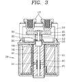
FIG. 3 is a sectional view illustrating an electromagnetic relay in accordance with an embodiment of the present invention; -
FIG. 4 is an enlarged view illustrating an arc protector ofFIG. 3 ; -
FIG. 5 is a partially cut-out perspective view illustrating the arc protector ofFIG. 4 ; -
FIG. 6 is an enlarged view illustrating the arc protector ofFIG. 3 ; -
FIG. 7 is a sectional view illustrating another example of the arc protector ofFIG. 3 ; -
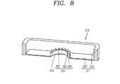
FIG. 8 is a partially cut-out perspective view illustrating the arc protector ofFIG. 7 ; -
FIG. 9 is a sectional view illustrating another example of the arc protector ofFIG. 3 ; -
FIG. 10 is an enlarged view illustrating the arc protector ofFIG. 9 ; -
FIG. 11 is a sectional view illustrating another example of the protrusion ofFIG. 7 ; and -
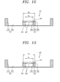
FIGS. 12 and 13 are sectional views illustrating another example of the arc protector ofFIG. 3 , respectively; - Hereinafter, a preferred embodiment of an electromagnetic relay according to the present invention will be described in detail with reference to the accompanying drawings.
- As shown in
FIGS. 3 and4 , an electromagnetic relay according to an embodiment of the present invention may include ahousing 110; a fixedcontact 115 provided within thehousing 110; amovable contact 121 disposed within thehousing 110 so as to be in contact with and separated from the fixedcontact 115; adriving unit 130 configured to drive themovable contact 121 and including ashaft 181 having one end connected to themovable contact 121 and acompression spring 201 for applying an elastic force to themovable contact 121 so as to be in contact with the fixedcontact 115; and anarc protector 210 including anarc shielding portion 211 for shielding an arc and a compressionspring support portion 221 formed to protrude from thearc shielding portion 211 to support thecompression spring 201. - The
housing 110 may have an accommodating space therein. - The
housing 110 may be formed of a ceramic material. - The
housing 110 may be formed to be open at its lower part. - The fixed
contact 115 may be provided within thehousing 110. - The fixed
contact 115 may be coupled to an upper end of thehousing 110. - The
movable contact 121, configured to be in contact with and separated from the fixedcontact 115, may be provided within thehousing 110. - The driving
unit 130, configured to drive themovable contact 121 so as to be in contact with and separated from the fixedcontact 115, may be provided at one side of thehousing 110. - The driving
unit 130 may be disposed at a lower side of thehousing 110. - The driving
unit 130 may include acoil 141 configured to generate an electromagnetic force, ayoke 151 disposed around thecoil 141 to form a magnetic path, a fixedcore 161 disposed within thecoil 141, amovable core 171 movably disposed to be close to and spaced from the fixedcore 161, ashaft 181 having one end connected to themovable core 171 and another end connected to themovable contact 121, and arestoration spring 191 configured to apply an elastic force to themovable core 171 so as to be spaced from the fixedcore 161. - The
coil 141 may be formed in a cylindrical shape. - The
bobbin 145 may be provided within thecoil 141. - The fixed
core 161 and themovable core 171 may be inserted into thebobbin 145. - A
restoration spring 191 may be provided between the fixedcore 161 and themovable core 171 to apply an elastic force thereto so that the fixedcore 161 and themovable core 171 may be spaced from each other. - An upper end of the fixed
core 161 may be configured to protrude toward an upper side of theyoke 151 at a predetermined height. - An
accommodating portion 164 may be provided within the fixedcore 161 so that theshaft 181 may be accommodated and relatively movable therein. - The
movable contact 121 may be formed of an electrically-conductive material. - An end of the
shaft 181 may be connected to themovable contact 121 so as to be relative movable. - An
insertion hole 125 may be provided on themovable contact 121 so that an end of theshaft 181 may be inserted and relatively movable therein. - The
shaft 181 may include ashaft body 183 and a movablecontact coupling portion 185 formed to protrude from one side of theshaft body 183 and to be in connect with themovable contact 121. - The
shaft body 183 may be accommodated and coupled to theaccommodating portion 164 of the fixedcore 161. - The movable
contact coupling portion 185 may have a smaller outer diameter than theshaft body 183. - The movable
contact coupling portion 185 may be inserted and coupled to theinsertion hole 125 of themovable contact 121. - The
compression spring 201, configured to apply an elastic force to themovable contact 121 so as to be in elastically contact with the fixedcontact 115 with a predetermined pressure, may be provided at one side of themovable contact 121. - The
compression spring 201 may be implemented by a compression coil spring. - An end of the
shaft 181 may be inserted and coupled within thecompression spring 201. - The movable
contact coupling portion 185 may be inserted into thecompression spring 201. - The
arc protector 210 may be provided at a lower side of themovable contact 121. - The
arc protector 210 may be provided at a lower opening portion of thehousing 110. - A
seal cup 112 may be provided at an outer peripheral surface of thearc protector 210. - The
arc protector 210 may include anarc shielding portion 211 configured to protect thedriving unit 130 from an arc generated by the fixedcontact 115 and themovable contact 121; and a compressionspring support portion 221 formed at a central part of thearc shielding portion 211 and configured to support thecompression spring 201. - The
arc protector 210 may be formed of a material exhibiting an electric insulation and an impact buffering performance. - The
arc protector 210 may be formed of rubber. - The
arc shielding portion 211 may include abottom portion 213 and aside wall portion 215 protruded from a peripheral edge of thebottom portion 213. - The
side wall portion 215 of thearc shielding portion 211 may be configured to be inserted into thehousing 110. - The
side wall portion 215 of thearc shielding portion 211 may be configured to be in surface-contact with an inner surface of thehousing 110. - The
side wall portion 215 of thearc shielding portion 211 may be configured to be tight-fitted into thehousing 110 at its upper peripheral flange portion. Under such a configuration, leakage of an arc generated between thefixed contact 115 and themovable contact 121 can be prevented. - A compression
spring support portion 221 may be provided at a central portion of thearc shielding portion 211. - The compression
spring support portion 221 may be formed to protrude from thebottom portion 213 of thearc shielding portion 211. - The compression
spring support portion 221 may be formed to have a cylindrical shape to accommodate therein theshaft 181. - The compression
spring support portion 221 includes ashaft accommodating portion 224 for accommodating theshaft 181 therein. - The compression
spring support portion 221 may be configured to protrude over an upper end of theshaft body 183 in an initial position where themovable contact 121 is spaced from the fixedcontact 115. - The compression
spring support portion 221 may include a fixedcore accommodating portion 225 at its lower part to accommodate therein anupper end 163 of the fixedcore 161. Under such a configuration, thearc protector 210 can be fixedly coupled. - More specifically, the
arc protector 210 can be firmly coupled without any lateral movement due to such a configuration that theside wall portion 215 of thearc shielding portion 211 is tight-fitted into thehousing 110, and the fixedcore accommodating portion 225 of the compressionspring support portion 225 of thearc shielding portion 211 is coupled with theupper portion 163 of the fixedcore 161. - The fixed
core accommodating portion 225 may be provided at a lower part of the compressionspring support portion 221. - The fixed
core accommodating portion 225 may be formed by cutting out part of the compressionspring support portion 221 to extend outward in a radius direction. - An
upper end 223 of the compressionspring support portion 221 may be configured to be a flat surface. - A
washer 201 may be provided between theupper end 223 of the compressionspring support portion 221 and thecompression spring 201. - The movable
contact coupling portion 185 may be accommodated and coupled to a through-hole 232 of thewasher 231. - The compression
spring support portion 221 may be configured to have an outer diameter larger than those of thewasher 231 and thecompression spring 201. - The
washer 231 may surface-contact with theupper end 223 of the compressionspring support portion 221. - A buffering
member 241 may be provided between thewasher 231 and theshaft 181. Under such a configuration, a direct contact of thewasher 231 and theshaft 181 may be avoided, and thus it is possible to prevent noise which may be generated by a contact between metal members. - The
buffer member 241 may be configured to have a disk shape. - The
buffer member 241 may be configured to have an outer diameter smaller than an inner diameter of the compressionspring support portion 221. - The
buffer member 241 may include, at a central portion thereof, a through-hole 245 through which theshaft 181 passes. - More specifically, an inner diameter of the through-
hole 245 may be larger than an outer diameter of the movablecontact coupling portion 185. - As shown in
FIGS. 7 and8 , thearc protector 210 may include a plurality ofprotrusions 227 which are protruded toward thecompression spring 201. - The
arc protector 210 may include thearc shielding portion 211; and the compressionspring support portion 221 configured to support thecompression spring 201, and formed at a center portion of thearc shielding portion 211 to protrude toward thecompression spring 201. - The compression
spring support portion 221 may include thecylindrical portion 222 formed to protrude from thebottom portion 213 of thearc shielding portion 211 in a cylindrical shape, and a plurality ofprotrusions 227 which are formed at an upper edge of thecylindrical portion 222 to protrude toward thecompression spring 201 and spaced from each other in a circumferential direction. - The
cylindrical portion 222 may include a fixedcore accommodating portion 225 configured to accommodate therein anupper portion 163 of the fixedcore 161. - Each of the
protrusions 227 may be configured such that its outer width is gradually decreased toward thecompression spring 201. Under such a configuration, in an initial contact state between theprotrusions 227 and thewasher 231, buffering is performed therebetween, thereby restraining generation of noise. - The
washer 231 may be provided at an upper side of theprotrusions 227. - The
protrusions 227 may be configured to have a triangular shape. - In this embodiment of the present invention, the
protrusions 227 are formed in a triangular shape, but may be configured to have a semicircular shaped cross section, as shown inFIG. 11 . - As shown in
FIGS. 9 and 10 , thearc protector 210 may include a guidingportion 229 disposed at an outer peripheral portion of thecompression spring 201. - The
arc protector 210 may include anarc shielding portion 211, and a compressionspring support portion 221 provided at a central part thereof to protrude toward thecompression spring 201 and configured to support thecompression spring 201. - The compression
spring support portion 221 may include acylindrical portion 222 formed to protrude from thebottom portion 213 of thearc shielding portion 211 in a cylindrical shape, and the guidingportion 229 disposed at an outer peripheral portion of thecompression spring 201 to protrude from an upper end of thecylindrical portion 222. - The guiding
portion 222 may be configured to have a cylindrical shape which is protruded from the upper end of thecylindrical portion 222 toward themovable contact 121 and extended along a circumferential direction in a cylindrical shape. - The
cylindrical portion 222 may include the fixedcore accommodating portion 225 in which an upper end of the fixedcore 161 is accommodated. - The guiding
portion 229 may be configured to have an enlarged inner diameter Di2, when compared with an inner diameter Di1 of thecylindrical portion 222. - A
washer accommodating portion 230 may be provided in the guidingportion 229 to accommodate therein thewasher 231. - The
washer 231 may be disposed on an upper portion of thecylindrical portion 222. - As shown in
FIG. 12 , thecylindrical portion 222 may have a plurality oftriangle protrusions 227 at its upper peripheral edge. Under such a configuration, a contact area between thewasher 231 and theprotrusions 227 in an initial contact state may be relatively small and a buffering may be easily performed, thereby reducing noise. - As shown in
FIG. 13 , thecylindrical portion 222 may include a plurality ofprotrusions 228 having a semicircular cross section. Under such a configuration, a contact area between thewasher 231 and theprotrusions 228 in an initial contact state may be relatively small and a buffering may be easily performed, thereby reducing noise. - Under such a configuration, the
arc protector 210 may be coupled such that an upper end of the fixedcore 161 protruded toward an upper portion of theyoke 151 is accommodated within the fixedcore accommodating portion 225. - The
shaft 181 may be pre-assembled with thebuffer member 241, thewasher 231, thecompression spring 201, and themovable contact 121. - The lower end of the
shaft 181 may be inserted into and coupled with the fixedcore 161. - The lower end of the
shaft 181 may be inserted into inside of themovable core 171 and integrally coupled thereto. For instance, the lower end of theshaft 181 may be coupled to themovable core 171 by welding. - The
housing 110 may be coupled to the upper portion of thearc protector 210. - Meanwhile, when a power is applied to the
coil 141 of the drivingunit 30, themovable core 171 is moved toward the fixedcore 161 by an electromagnetic force generated therebetween. - The
shaft 181 and themovable core 121 may be moved toward the fixedcontact 115 at the same time when themovable core 171 moves. At this moment, therestoration spring 191 is compressed to accumulate an elastic force. - The
movable contact 121 which has been moved may contact thefixed contact 115 and thereafter stop moving. - An arc may be generated when the
movable contact 121 and the fixedcontact 115 are in contact with each other and/or separated from each other, and the arc generated therebetween can be prevented from being scattered to the periphery by thearc protector 210. - The
shaft 181 and themovable core 171 may be moved relative to themovable contact 121 until themovable core 171 contacts the fixedcore 161. At this moment, thecompression spring 201 is compressed to accumulate an elastic force. - More specifically, once the
movable contact 121 stops its movement after themovable contact 121 contacts the fixedcontact 115, thewasher 231 may be compressed by theshaft 181 and then spaced from the compressionspring support portion 221. As thewasher 231 is moved, thecompression spring 201 is compressed to accumulate an elastic force. Thus, themovable contact 121 may stably contact thefixed contact 115 with a predetermined compression force. - Meanwhile, when a power supply to the
coil 141 of thedriving unit 130 is stopped, themovable core 171 may be spaced from the fixedcore 161 by the elastic force of therestoration spring 191 and then returns to its initial position. - When the
movable core 171 is moved, theshaft 181 may return to its initial position. As theshaft 181 moves, thecompression spring 201 may be elongated. - When the
compression spring 201 starts to be elongated, thewasher 231 may be moved toward the compressionspring support portion 221. - At this moment, the
washer 231 may be buffered by thebuffer member 241 or theprotrusions - As described above, according to an embodiment of the present invention, the number of the components and man-hours can be reduced by providing the arc protector including the arc shielding portion and the compression spring support portion.
- Further, both arc protection and buffering and support of the compression spring can be implemented with a single component, by providing the spring support portion and the arc shielding portion which are formed integrally.
- Further, the compression spring can be stably supported without generating a gap of the compression spring support portion, by providing the spring support portion and the arc shielding portion which are formed integrally.
- Further, the outer peripheral and central portions of the arc protector can be firmly supported, by providing the fixed core accommodating portion at the compression spring support portion.
- As the present features may be embodied in several forms without departing from the characteristics thereof, it should also be understood that the above-described embodiments are not limited by any of the details of the foregoing description, unless otherwise specified, but rather should be construed broadly within its scope as defined in the appended claims, and therefore all changes and modifications that fall within the metes and bounds of the claims, or equivalents of such metes and bounds are therefore intended to be embraced by the appended claims.
Claims (14)
- An electromagnetic relay, characterized by comprising:a housing (110);a fixed contact (115) provided within the housing (110);a movable contact (121) disposed within the housing (110) so as to be in contact with and separated from the fixed contact (115);a driving unit (130) configured to drive the movable contact (121), and including a shaft (181) having one end connected to the movable contact (121) and a compression spring (201) for applying an elastic force to the movable contact (121) so as to be in contact with the fixed contact (115); andan arc protector (210) including an arc shielding portion (211) for shielding an arc, and a compression spring support portion (221) formed to protrude from the arc shielding portion (211) to support the compression spring (201), the compression spring support portion (221) comprising a shaft accommodating portion (224) for accommodating the shaft (181) therein.
- The electromagnetic relay of claim 1, further comprising a washer (231) disposed between the compression spring support portion (221) and the compression spring (201).
- The electromagnetic relay of claim 2, wherein the compression spring support portion (221) includes a plurality of protrusions (227,228) protruded toward the compression spring (201) for supporting the washer (231).
- The electromagnetic relay of claim 3, wherein each of the protrusions (227,228) is configured such that its outer width is gradually decreased toward the compression spring (201).
- The electromagnetic relay of claim 4, wherein each of the protrusions (227) has a triangular cross section.
- The electromagnetic relay of claim 4, wherein each of the protrusions (228) has a semicircular cross section.
- The electromagnetic relay of any one of claims 2 to 6, wherein the compression spring support portion (221) includes a guiding portion (229) disposed at an outer side of the compression spring (201).
- The electromagnetic relay of claim 7, wherein the guiding portion (229) includes a washer accommodating portion (230) to accommodate therein the washer (231).
- The electromagnetic relay of claim 8, wherein the compression spring support portion (221) includes a cylindrical portion (222) having the shaft accommodating portion (224) therein, and
wherein the guiding portion (229) is configured to protrude from the cylindrical portion (222) and has an extended inner diameter than an inner diameter of the cylindrical portion (222). - The electromagnetic relay of any one of claims 2 to 9, further comprising a buffer member (241) disposed between the washer (231) and the shaft (181).
- The electromagnetic relay of any one of claims 1 to 9, wherein the driving unit (130) further comprises:a coil (141);a fixed core (161) disposed within the coil (141); anda movable core (171) movably disposed to be close to and spaced from the fixed core (161) and having an end connected to the shaft (181),wherein the compression spring support portion (221) includes a fixed core accommodating portion (225) to accommodate therein one end of the fixed core (161).
- The electromagnetic relay of claim 11, wherein the fixed core accommodating portion (225) is configured to extend in a radius direction from the shaft accommodating portion (224).
- The electromagnetic relay of claim 11 or 12, wherein the arc shielding portion (211) includes a bottom portion (213) and a side wall portion (215) formed to protrude along a peripheral portion of the bottom portion (213), and wherein the side wall portion (215) is closely inserted and coupled within the inner surface of the housing (110).
- The electromagnetic relay of claim 13, wherein the side wall portion (215) is tight-fitted within an inner surface of the housing (110).
Applications Claiming Priority (1)
| Application Number | Priority Date | Filing Date | Title |
|---|---|---|---|
| KR2020140000611U KR200486560Y1 (en) | 2014-01-27 | 2014-01-27 | Electromagnetic relay |
Publications (3)
| Publication Number | Publication Date |
|---|---|
| EP2899732A2 true EP2899732A2 (en) | 2015-07-29 |
| EP2899732A3 EP2899732A3 (en) | 2015-08-26 |
| EP2899732B1 EP2899732B1 (en) | 2018-09-19 |
Family
ID=51753137
Family Applications (1)
| Application Number | Title | Priority Date | Filing Date |
|---|---|---|---|
| EP14190082.9A Active EP2899732B1 (en) | 2014-01-27 | 2014-10-23 | Electromagnetic relay |
Country Status (6)
| Country | Link |
|---|---|
| US (1) | US9496109B2 (en) |
| EP (1) | EP2899732B1 (en) |
| JP (1) | JP5990240B2 (en) |
| KR (1) | KR200486560Y1 (en) |
| CN (1) | CN104810207B (en) |
| ES (1) | ES2701190T3 (en) |
Families Citing this family (24)
| Publication number | Priority date | Publication date | Assignee | Title |
|---|---|---|---|---|
| JP5938745B2 (en) * | 2012-07-06 | 2016-06-22 | パナソニックIpマネジメント株式会社 | Contact device and electromagnetic relay equipped with the contact device |
| CN105359243B (en) | 2013-06-28 | 2018-06-05 | 松下知识产权经营株式会社 | Contact device and electromagnetic relay equipped with the contact device |
| JP6590273B2 (en) * | 2015-04-13 | 2019-10-16 | パナソニックIpマネジメント株式会社 | Contact device and electromagnetic relay |
| DE102015212801A1 (en) * | 2015-07-08 | 2017-01-12 | Te Connectivity Germany Gmbh | Electrical switching arrangement with improved linear storage |
| KR101943365B1 (en) * | 2015-10-14 | 2019-01-29 | 엘에스산전 주식회사 | Direct Relay |
| CN205211669U (en) * | 2015-11-30 | 2016-05-04 | 比亚迪股份有限公司 | Pushing mechanism of relay and have its relay |
| CN107204256B (en) * | 2016-03-18 | 2019-06-25 | 比亚迪股份有限公司 | relay |
| CN107204254B (en) * | 2016-03-18 | 2019-08-13 | 比亚迪股份有限公司 | A kind of relay |
| CN107204255B (en) * | 2016-03-18 | 2019-04-19 | 比亚迪股份有限公司 | a relay |
| CN107204258B (en) | 2016-03-18 | 2019-06-25 | 比亚迪股份有限公司 | Relay |
| CN107204251B (en) * | 2016-03-18 | 2019-08-13 | 比亚迪股份有限公司 | Relay |
| CN107204253B (en) | 2016-03-18 | 2019-04-19 | 比亚迪股份有限公司 | a relay |
| CN107452551A (en) * | 2016-05-31 | 2017-12-08 | 比亚迪股份有限公司 | Relay |
| CN107331582A (en) * | 2017-09-06 | 2017-11-07 | 上海瑞垒电子科技有限公司 | A kind of high-low pressure isolated form HVDC relay |
| CN109036969B (en) * | 2018-08-07 | 2019-10-08 | 速达(泰州)新能源有限公司 | A kind of relay for preventing overload from bonding |
| CN109036976A (en) * | 2018-08-08 | 2018-12-18 | 三友联众集团股份有限公司 | Improved push rod assembly for relay |
| KR102324516B1 (en) * | 2019-05-29 | 2021-11-10 | 엘에스일렉트릭 (주) | Direct current relay |
| JP7351155B2 (en) * | 2019-09-13 | 2023-09-27 | オムロン株式会社 | electromagnetic relay |
| US11410968B2 (en) * | 2019-10-18 | 2022-08-09 | Taiwan Semiconductor Manufacturing Company, Ltd. | Semiconductor device and method of forming the same |
| CN111370267B (en) * | 2020-04-17 | 2025-04-25 | 苏州安来强电子科技有限公司 | Moving contact assembly for DC contactor |
| CN211980527U (en) * | 2020-05-29 | 2020-11-20 | 比亚迪股份有限公司 | relay |
| CN111916312B (en) * | 2020-08-12 | 2023-03-21 | 浙江众信新能源科技股份有限公司 | Relay contact assembly capable of resisting large short circuit current |
| CN112309775B (en) * | 2020-09-17 | 2022-10-18 | 华为数字能源技术有限公司 | Direct current contactor, distribution box, power battery assembly and vehicle |
| CN121215490A (en) * | 2024-06-25 | 2025-12-26 | 厦门宏发电力电器有限公司 | High voltage DC relay |
Family Cites Families (13)
| Publication number | Priority date | Publication date | Assignee | Title |
|---|---|---|---|---|
| US2892059A (en) * | 1958-04-03 | 1959-06-23 | Essex Wire Corp | Operating mechanism for electric switches |
| US4725801A (en) * | 1986-10-24 | 1988-02-16 | Hamilton Standard Controls, Inc. | Bistable solenoid switch |
| DE4117242C1 (en) * | 1991-05-27 | 1992-07-16 | Robert Bosch Gmbh, 7000 Stuttgart, De | |
| JP3711698B2 (en) | 1997-05-26 | 2005-11-02 | 松下電工株式会社 | Sealed contact device |
| JP2006019148A (en) * | 2004-07-01 | 2006-01-19 | Matsushita Electric Works Ltd | Electromagnetic switch |
| KR100845539B1 (en) * | 2005-03-28 | 2008-07-10 | 마츠시다 덴코 가부시키가이샤 | Contact device |
| KR100922542B1 (en) * | 2005-11-25 | 2009-10-21 | 파나소닉 전공 주식회사 | Electromagnetic switching device |
| US7852178B2 (en) | 2006-11-28 | 2010-12-14 | Tyco Electronics Corporation | Hermetically sealed electromechanical relay |
| EP3089189B1 (en) | 2008-03-19 | 2018-06-27 | Panasonic Intellectual Property Management Co., Ltd. | Contact device |
| JP5437949B2 (en) | 2010-08-11 | 2014-03-12 | 富士電機機器制御株式会社 | Contact device and electromagnetic contactor using the same |
| KR101072629B1 (en) * | 2010-10-15 | 2011-10-12 | 엘에스산전 주식회사 | Noise Reduction Electronic Switchgear |
| KR101137015B1 (en) * | 2010-10-15 | 2012-04-19 | 엘에스산전 주식회사 | Electromagnetic switching apparatus |
| WO2012060087A1 (en) * | 2010-11-01 | 2012-05-10 | 日本特殊陶業株式会社 | Relay |
-
2014
- 2014-01-27 KR KR2020140000611U patent/KR200486560Y1/en not_active Expired - Fee Related
- 2014-10-22 US US14/521,123 patent/US9496109B2/en active Active
- 2014-10-23 ES ES14190082T patent/ES2701190T3/en active Active
- 2014-10-23 EP EP14190082.9A patent/EP2899732B1/en active Active
- 2014-11-18 JP JP2014233926A patent/JP5990240B2/en not_active Expired - Fee Related
-
2015
- 2015-01-14 CN CN201510019167.7A patent/CN104810207B/en active Active
Non-Patent Citations (1)
| Title |
|---|
| None |
Also Published As
| Publication number | Publication date |
|---|---|
| ES2701190T3 (en) | 2019-02-21 |
| US20150213980A1 (en) | 2015-07-30 |
| KR20150003009U (en) | 2015-08-05 |
| US9496109B2 (en) | 2016-11-15 |
| EP2899732A3 (en) | 2015-08-26 |
| JP5990240B2 (en) | 2016-09-07 |
| CN104810207A (en) | 2015-07-29 |
| JP2015141894A (en) | 2015-08-03 |
| EP2899732B1 (en) | 2018-09-19 |
| CN104810207B (en) | 2017-04-12 |
| KR200486560Y1 (en) | 2018-06-07 |
Similar Documents
| Publication | Publication Date | Title |
|---|---|---|
| EP2899732B1 (en) | Electromagnetic relay | |
| EP2639804B1 (en) | Sealed contact device | |
| CN103915294B (en) | Contact arrangement and the electromagnetic relay for being equipped with the contact arrangement | |
| US8558648B2 (en) | Electromagnetic switching apparatus | |
| EP2899737B1 (en) | Electromagnetic relay | |
| US8766750B2 (en) | Electromagnetic switching apparatus | |
| EP2442328B1 (en) | Noise decreasing type electromagnetic switch | |
| EP2442329B1 (en) | Noise decreasing type electromagnetic switch | |
| EP2442342B1 (en) | Electromagnetic switching device | |
| EP3285277A1 (en) | Contact device | |
| KR20130085826A (en) | Vibration motor | |
| US11756759B2 (en) | Electromagnetic relay with modification of drive shaft or movable iron core | |
| JP7286931B2 (en) | electromagnetic relay | |
| KR101090503B1 (en) | Electronic switchgear | |
| JP7310508B2 (en) | relay | |
| KR20140001771U (en) | Solenoid structure | |
| JP2012199129A (en) | Contact device and electromagnetic relay equipped with the contact device | |
| KR200483575Y1 (en) | Electromagnetic contactor | |
| KR20110010997U (en) | Electronic switchgear | |
| JP2012199151A (en) | Contact device |
Legal Events
| Date | Code | Title | Description |
|---|---|---|---|
| PUAL | Search report despatched |
Free format text: ORIGINAL CODE: 0009013 |
|
| PUAI | Public reference made under article 153(3) epc to a published international application that has entered the european phase |
Free format text: ORIGINAL CODE: 0009012 |
|
| 17P | Request for examination filed |
Effective date: 20141023 |
|
| AK | Designated contracting states |
Kind code of ref document: A2 Designated state(s): AL AT BE BG CH CY CZ DE DK EE ES FI FR GB GR HR HU IE IS IT LI LT LU LV MC MK MT NL NO PL PT RO RS SE SI SK SM TR |
|
| AX | Request for extension of the european patent |
Extension state: BA ME |
|
| AK | Designated contracting states |
Kind code of ref document: A3 Designated state(s): AL AT BE BG CH CY CZ DE DK EE ES FI FR GB GR HR HU IE IS IT LI LT LU LV MC MK MT NL NO PL PT RO RS SE SI SK SM TR |
|
| AX | Request for extension of the european patent |
Extension state: BA ME |
|
| RIC1 | Information provided on ipc code assigned before grant |
Ipc: H01H 50/34 20060101ALI20150721BHEP Ipc: H01H 9/30 20060101AFI20150721BHEP |
|
| 17P | Request for examination filed |
Effective date: 20160211 |
|
| RBV | Designated contracting states (corrected) |
Designated state(s): AL AT BE BG CH CY CZ DE DK EE ES FI FR GB GR HR HU IE IS IT LI LT LU LV MC MK MT NL NO PL PT RO RS SE SI SK SM TR |
|
| GRAP | Despatch of communication of intention to grant a patent |
Free format text: ORIGINAL CODE: EPIDOSNIGR1 |
|
| STAA | Information on the status of an ep patent application or granted ep patent |
Free format text: STATUS: GRANT OF PATENT IS INTENDED |
|
| INTG | Intention to grant announced |
Effective date: 20180329 |
|
| RIN1 | Information on inventor provided before grant (corrected) |
Inventor name: LEE, KYOUNG JUN |
|
| GRAS | Grant fee paid |
Free format text: ORIGINAL CODE: EPIDOSNIGR3 |
|
| GRAA | (expected) grant |
Free format text: ORIGINAL CODE: 0009210 |
|
| STAA | Information on the status of an ep patent application or granted ep patent |
Free format text: STATUS: THE PATENT HAS BEEN GRANTED |
|
| AK | Designated contracting states |
Kind code of ref document: B1 Designated state(s): AL AT BE BG CH CY CZ DE DK EE ES FI FR GB GR HR HU IE IS IT LI LT LU LV MC MK MT NL NO PL PT RO RS SE SI SK SM TR |
|
| REG | Reference to a national code |
Ref country code: GB Ref legal event code: FG4D |
|
| REG | Reference to a national code |
Ref country code: CH Ref legal event code: EP |
|
| REG | Reference to a national code |
Ref country code: AT Ref legal event code: REF Ref document number: 1044193 Country of ref document: AT Kind code of ref document: T Effective date: 20181015 |
|
| REG | Reference to a national code |
Ref country code: IE Ref legal event code: FG4D |
|
| REG | Reference to a national code |
Ref country code: DE Ref legal event code: R096 Ref document number: 602014032452 Country of ref document: DE |
|
| REG | Reference to a national code |
Ref country code: FR Ref legal event code: PLFP Year of fee payment: 5 |
|
| REG | Reference to a national code |
Ref country code: NL Ref legal event code: MP Effective date: 20180919 |
|
| PG25 | Lapsed in a contracting state [announced via postgrant information from national office to epo] |
Ref country code: NO Free format text: LAPSE BECAUSE OF FAILURE TO SUBMIT A TRANSLATION OF THE DESCRIPTION OR TO PAY THE FEE WITHIN THE PRESCRIBED TIME-LIMIT Effective date: 20181219 Ref country code: BG Free format text: LAPSE BECAUSE OF FAILURE TO SUBMIT A TRANSLATION OF THE DESCRIPTION OR TO PAY THE FEE WITHIN THE PRESCRIBED TIME-LIMIT Effective date: 20181219 Ref country code: SE Free format text: LAPSE BECAUSE OF FAILURE TO SUBMIT A TRANSLATION OF THE DESCRIPTION OR TO PAY THE FEE WITHIN THE PRESCRIBED TIME-LIMIT Effective date: 20180919 Ref country code: RS Free format text: LAPSE BECAUSE OF FAILURE TO SUBMIT A TRANSLATION OF THE DESCRIPTION OR TO PAY THE FEE WITHIN THE PRESCRIBED TIME-LIMIT Effective date: 20180919 Ref country code: FI Free format text: LAPSE BECAUSE OF FAILURE TO SUBMIT A TRANSLATION OF THE DESCRIPTION OR TO PAY THE FEE WITHIN THE PRESCRIBED TIME-LIMIT Effective date: 20180919 Ref country code: LT Free format text: LAPSE BECAUSE OF FAILURE TO SUBMIT A TRANSLATION OF THE DESCRIPTION OR TO PAY THE FEE WITHIN THE PRESCRIBED TIME-LIMIT Effective date: 20180919 Ref country code: GR Free format text: LAPSE BECAUSE OF FAILURE TO SUBMIT A TRANSLATION OF THE DESCRIPTION OR TO PAY THE FEE WITHIN THE PRESCRIBED TIME-LIMIT Effective date: 20181220 |
|
| REG | Reference to a national code |
Ref country code: LT Ref legal event code: MG4D |
|
| REG | Reference to a national code |
Ref country code: ES Ref legal event code: FG2A Ref document number: 2701190 Country of ref document: ES Kind code of ref document: T3 Effective date: 20190221 |
|
| PG25 | Lapsed in a contracting state [announced via postgrant information from national office to epo] |
Ref country code: LV Free format text: LAPSE BECAUSE OF FAILURE TO SUBMIT A TRANSLATION OF THE DESCRIPTION OR TO PAY THE FEE WITHIN THE PRESCRIBED TIME-LIMIT Effective date: 20180919 Ref country code: HR Free format text: LAPSE BECAUSE OF FAILURE TO SUBMIT A TRANSLATION OF THE DESCRIPTION OR TO PAY THE FEE WITHIN THE PRESCRIBED TIME-LIMIT Effective date: 20180919 Ref country code: AL Free format text: LAPSE BECAUSE OF FAILURE TO SUBMIT A TRANSLATION OF THE DESCRIPTION OR TO PAY THE FEE WITHIN THE PRESCRIBED TIME-LIMIT Effective date: 20180919 |
|
| REG | Reference to a national code |
Ref country code: AT Ref legal event code: MK05 Ref document number: 1044193 Country of ref document: AT Kind code of ref document: T Effective date: 20180919 |
|
| PG25 | Lapsed in a contracting state [announced via postgrant information from national office to epo] |
Ref country code: RO Free format text: LAPSE BECAUSE OF FAILURE TO SUBMIT A TRANSLATION OF THE DESCRIPTION OR TO PAY THE FEE WITHIN THE PRESCRIBED TIME-LIMIT Effective date: 20180919 Ref country code: CZ Free format text: LAPSE BECAUSE OF FAILURE TO SUBMIT A TRANSLATION OF THE DESCRIPTION OR TO PAY THE FEE WITHIN THE PRESCRIBED TIME-LIMIT Effective date: 20180919 Ref country code: IS Free format text: LAPSE BECAUSE OF FAILURE TO SUBMIT A TRANSLATION OF THE DESCRIPTION OR TO PAY THE FEE WITHIN THE PRESCRIBED TIME-LIMIT Effective date: 20190119 Ref country code: PL Free format text: LAPSE BECAUSE OF FAILURE TO SUBMIT A TRANSLATION OF THE DESCRIPTION OR TO PAY THE FEE WITHIN THE PRESCRIBED TIME-LIMIT Effective date: 20180919 Ref country code: NL Free format text: LAPSE BECAUSE OF FAILURE TO SUBMIT A TRANSLATION OF THE DESCRIPTION OR TO PAY THE FEE WITHIN THE PRESCRIBED TIME-LIMIT Effective date: 20180919 Ref country code: AT Free format text: LAPSE BECAUSE OF FAILURE TO SUBMIT A TRANSLATION OF THE DESCRIPTION OR TO PAY THE FEE WITHIN THE PRESCRIBED TIME-LIMIT Effective date: 20180919 Ref country code: EE Free format text: LAPSE BECAUSE OF FAILURE TO SUBMIT A TRANSLATION OF THE DESCRIPTION OR TO PAY THE FEE WITHIN THE PRESCRIBED TIME-LIMIT Effective date: 20180919 |
|
| PG25 | Lapsed in a contracting state [announced via postgrant information from national office to epo] |
Ref country code: SK Free format text: LAPSE BECAUSE OF FAILURE TO SUBMIT A TRANSLATION OF THE DESCRIPTION OR TO PAY THE FEE WITHIN THE PRESCRIBED TIME-LIMIT Effective date: 20180919 Ref country code: SM Free format text: LAPSE BECAUSE OF FAILURE TO SUBMIT A TRANSLATION OF THE DESCRIPTION OR TO PAY THE FEE WITHIN THE PRESCRIBED TIME-LIMIT Effective date: 20180919 Ref country code: PT Free format text: LAPSE BECAUSE OF FAILURE TO SUBMIT A TRANSLATION OF THE DESCRIPTION OR TO PAY THE FEE WITHIN THE PRESCRIBED TIME-LIMIT Effective date: 20190119 |
|
| REG | Reference to a national code |
Ref country code: CH Ref legal event code: PL |
|
| REG | Reference to a national code |
Ref country code: DE Ref legal event code: R097 Ref document number: 602014032452 Country of ref document: DE |
|
| REG | Reference to a national code |
Ref country code: BE Ref legal event code: MM Effective date: 20181031 |
|
| PG25 | Lapsed in a contracting state [announced via postgrant information from national office to epo] |
Ref country code: LU Free format text: LAPSE BECAUSE OF NON-PAYMENT OF DUE FEES Effective date: 20181023 |
|
| REG | Reference to a national code |
Ref country code: IE Ref legal event code: MM4A |
|
| PLBE | No opposition filed within time limit |
Free format text: ORIGINAL CODE: 0009261 |
|
| STAA | Information on the status of an ep patent application or granted ep patent |
Free format text: STATUS: NO OPPOSITION FILED WITHIN TIME LIMIT |
|
| PG25 | Lapsed in a contracting state [announced via postgrant information from national office to epo] |
Ref country code: DK Free format text: LAPSE BECAUSE OF FAILURE TO SUBMIT A TRANSLATION OF THE DESCRIPTION OR TO PAY THE FEE WITHIN THE PRESCRIBED TIME-LIMIT Effective date: 20180919 Ref country code: MC Free format text: LAPSE BECAUSE OF FAILURE TO SUBMIT A TRANSLATION OF THE DESCRIPTION OR TO PAY THE FEE WITHIN THE PRESCRIBED TIME-LIMIT Effective date: 20180919 |
|
| 26N | No opposition filed |
Effective date: 20190620 |
|
| PG25 | Lapsed in a contracting state [announced via postgrant information from national office to epo] |
Ref country code: BE Free format text: LAPSE BECAUSE OF NON-PAYMENT OF DUE FEES Effective date: 20181031 Ref country code: LI Free format text: LAPSE BECAUSE OF NON-PAYMENT OF DUE FEES Effective date: 20181031 Ref country code: CH Free format text: LAPSE BECAUSE OF NON-PAYMENT OF DUE FEES Effective date: 20181031 |
|
| PG25 | Lapsed in a contracting state [announced via postgrant information from national office to epo] |
Ref country code: SI Free format text: LAPSE BECAUSE OF FAILURE TO SUBMIT A TRANSLATION OF THE DESCRIPTION OR TO PAY THE FEE WITHIN THE PRESCRIBED TIME-LIMIT Effective date: 20180919 Ref country code: IE Free format text: LAPSE BECAUSE OF NON-PAYMENT OF DUE FEES Effective date: 20181023 |
|
| PG25 | Lapsed in a contracting state [announced via postgrant information from national office to epo] |
Ref country code: MT Free format text: LAPSE BECAUSE OF NON-PAYMENT OF DUE FEES Effective date: 20181023 |
|
| PG25 | Lapsed in a contracting state [announced via postgrant information from national office to epo] |
Ref country code: TR Free format text: LAPSE BECAUSE OF FAILURE TO SUBMIT A TRANSLATION OF THE DESCRIPTION OR TO PAY THE FEE WITHIN THE PRESCRIBED TIME-LIMIT Effective date: 20180919 |
|
| PG25 | Lapsed in a contracting state [announced via postgrant information from national office to epo] |
Ref country code: CY Free format text: LAPSE BECAUSE OF FAILURE TO SUBMIT A TRANSLATION OF THE DESCRIPTION OR TO PAY THE FEE WITHIN THE PRESCRIBED TIME-LIMIT Effective date: 20180919 Ref country code: MK Free format text: LAPSE BECAUSE OF NON-PAYMENT OF DUE FEES Effective date: 20180919 Ref country code: HU Free format text: LAPSE BECAUSE OF FAILURE TO SUBMIT A TRANSLATION OF THE DESCRIPTION OR TO PAY THE FEE WITHIN THE PRESCRIBED TIME-LIMIT; INVALID AB INITIO Effective date: 20141023 |
|
| PGFP | Annual fee paid to national office [announced via postgrant information from national office to epo] |
Ref country code: GB Payment date: 20220905 Year of fee payment: 9 |
|
| P01 | Opt-out of the competence of the unified patent court (upc) registered |
Effective date: 20230625 |
|
| GBPC | Gb: european patent ceased through non-payment of renewal fee |
Effective date: 20231023 |
|
| PG25 | Lapsed in a contracting state [announced via postgrant information from national office to epo] |
Ref country code: GB Free format text: LAPSE BECAUSE OF NON-PAYMENT OF DUE FEES Effective date: 20231023 |
|
| PG25 | Lapsed in a contracting state [announced via postgrant information from national office to epo] |
Ref country code: GB Free format text: LAPSE BECAUSE OF NON-PAYMENT OF DUE FEES Effective date: 20231023 |
|
| PGFP | Annual fee paid to national office [announced via postgrant information from national office to epo] |
Ref country code: IT Payment date: 20250909 Year of fee payment: 12 |
|
| PGFP | Annual fee paid to national office [announced via postgrant information from national office to epo] |
Ref country code: FR Payment date: 20250909 Year of fee payment: 12 |
|
| PGFP | Annual fee paid to national office [announced via postgrant information from national office to epo] |
Ref country code: DE Payment date: 20250908 Year of fee payment: 12 |
|
| PGFP | Annual fee paid to national office [announced via postgrant information from national office to epo] |
Ref country code: ES Payment date: 20251117 Year of fee payment: 12 |