EP2899706B9 - Method and system for analyzing human behavior in an intelligent surveillance system - Google Patents
Method and system for analyzing human behavior in an intelligent surveillance system Download PDFInfo
- Publication number
- EP2899706B9 EP2899706B9 EP14160409.0A EP14160409A EP2899706B9 EP 2899706 B9 EP2899706 B9 EP 2899706B9 EP 14160409 A EP14160409 A EP 14160409A EP 2899706 B9 EP2899706 B9 EP 2899706B9
- Authority
- EP
- European Patent Office
- Prior art keywords
- points
- silhouette
- trajectories
- behavior
- moving
- Prior art date
- Legal status (The legal status is an assumption and is not a legal conclusion. Google has not performed a legal analysis and makes no representation as to the accuracy of the status listed.)
- Not-in-force
Links
Images


Classifications
-
- G—PHYSICS
- G06—COMPUTING; CALCULATING OR COUNTING
- G06V—IMAGE OR VIDEO RECOGNITION OR UNDERSTANDING
- G06V40/00—Recognition of biometric, human-related or animal-related patterns in image or video data
- G06V40/20—Movements or behaviour, e.g. gesture recognition
-
- G—PHYSICS
- G08—SIGNALLING
- G08B—SIGNALLING OR CALLING SYSTEMS; ORDER TELEGRAPHS; ALARM SYSTEMS
- G08B13/00—Burglar, theft or intruder alarms
- G08B13/18—Actuation by interference with heat, light, or radiation of shorter wavelength; Actuation by intruding sources of heat, light, or radiation of shorter wavelength
- G08B13/189—Actuation by interference with heat, light, or radiation of shorter wavelength; Actuation by intruding sources of heat, light, or radiation of shorter wavelength using passive radiation detection systems
- G08B13/194—Actuation by interference with heat, light, or radiation of shorter wavelength; Actuation by intruding sources of heat, light, or radiation of shorter wavelength using passive radiation detection systems using image scanning and comparing systems
- G08B13/196—Actuation by interference with heat, light, or radiation of shorter wavelength; Actuation by intruding sources of heat, light, or radiation of shorter wavelength using passive radiation detection systems using image scanning and comparing systems using television cameras
- G08B13/19602—Image analysis to detect motion of the intruder, e.g. by frame subtraction
- G08B13/19613—Recognition of a predetermined image pattern or behaviour pattern indicating theft or intrusion
-
- G—PHYSICS
- G06—COMPUTING; CALCULATING OR COUNTING
- G06T—IMAGE DATA PROCESSING OR GENERATION, IN GENERAL
- G06T7/00—Image analysis
- G06T7/20—Analysis of motion
- G06T7/246—Analysis of motion using feature-based methods, e.g. the tracking of corners or segments
-
- G—PHYSICS
- G06—COMPUTING; CALCULATING OR COUNTING
- G06T—IMAGE DATA PROCESSING OR GENERATION, IN GENERAL
- G06T2207/00—Indexing scheme for image analysis or image enhancement
- G06T2207/10—Image acquisition modality
- G06T2207/10016—Video; Image sequence
-
- G—PHYSICS
- G06—COMPUTING; CALCULATING OR COUNTING
- G06T—IMAGE DATA PROCESSING OR GENERATION, IN GENERAL
- G06T2207/00—Indexing scheme for image analysis or image enhancement
- G06T2207/30—Subject of image; Context of image processing
- G06T2207/30232—Surveillance
-
- G—PHYSICS
- G06—COMPUTING; CALCULATING OR COUNTING
- G06T—IMAGE DATA PROCESSING OR GENERATION, IN GENERAL
- G06T2207/00—Indexing scheme for image analysis or image enhancement
- G06T2207/30—Subject of image; Context of image processing
- G06T2207/30241—Trajectory
Definitions
- the present invention relates to analysis of human behavior, involving description and identification of actions, in order to automatically recognize behavior type in an intelligent surveillance system.
- a US patent US8131012 presents a method and a system for analyzing and learning behavior based on an acquired stream of video frames. Objects depicted in the stream are determined based on an analysis of the video frames. Each object may have a corresponding search model used to track an object's motion frame-to-frame. Classes of the objects are determined and semantic representations of the objects are generated.
- a US patent application US2003/0107650 discloses a surveillance and security system for automatic detection and warning of detected events, which includes a unit for observing behavior in a predetermined area under surveillance, a unit for processing an output of observed behavior from the unit for observing, and a pattern recognition module for recognizing whether the observed behavior is associated with predefined suspicious behaviors.
- the pattern recognition module may include infrared heat profiles of persons, images of actual people, sequences of people manipulating shopping bags, sounds of tearing of different types of packaging. The observation of motion, which is related to behavior, is compared against a database of predefined acts.
- a US patent US5666157 presents a surveillance system having at least one primary video camera for translating real images of a zone into electronic video signals at a first level of resolution.
- the system includes means for sampling movements of an individual or individuals located within the zone from the video signal output from at least one video camera.
- Video signal of sampled movements of the individual is electronically compared with known characteristics of movements which are indicative of individuals having a criminal intent.
- a US patent application US2011205359 presents a video surveillance system, which includes a model database storing a plurality of models and a vector database storing a plurality of vectors of recently observed trajectories.
- the trajectories are built for silhouettes which bound the whole observed object and therefore a single object is described by a single trajectory.
- the object of the invention is a system and a method for analyzing behavior in an intelligent surveillance system, according to the appended claims.
- the presented method is particularly useful for automatic recognition of human behavior and can be used in intelligent surveillance systems, including systems having a single stationary camera.
- these quantities take the form of electrical or magnetic signals capable of being stored, transferred, combined, compared, and otherwise manipulated in a computer system.
- these signals are referred to as bits, packets, messages, values, elements, symbols, characters, terms, numbers, or similar.
- the behavior of a person can be described by a set of trajectories of characteristic points of the person, as shown in Fig. 1 .
- a set of characteristic points at a given time defines a pose.
- a set of poses defined for consecutive time points or a set of time vectors for individual points forms a descriptor.
- the set of points to define a pose may have a different configuration for different types of behavior to be detected.
- a set of points is generated having a configuration different than a set of points for another type of behavior. For example:
- NCM negative curvature minima
- contour convexity may be used to describe the curvature.
- the method utilizing contour convexity is called positive curvature maxima (PCM) points.
- PCM positive curvature maxima
- the extreme points P1 and P2 in Fig. 3 are selected from the convex contour so that P1 is the point closing the i-th concavity and P2 is a point opening the i+1-th concavity.
- Fig. 2 shows an example of a PCM point 201. Among so selected pair of points, from the contour a PCM point is selected so that the distance from the segment
- the first method is called "Midpoint and four extreme points”. This is well suited for detecting behavior, in which human limbs are widely positioned, for example, while waving person's arms or crying for help.
- Another example method also utilizing the concept of the "Midpoint and four extreme points", applies a different normalization process.
- a third method is called "Points evenly spread on the contour".
- the method of points selection is based on selection of evenly spread, arbitrary number of points from the contour typically of a silhouette). Such approach allows for gradual selection of the level of contour mapping.
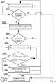
- the method has been depicted in Fig. 4 , wherein the following references refer to:
- the selected contour points define a descriptor of the contour (typically of a silhouette of a person) in a given video frame and are buffered in an output vector as shown in Fig. 4 .
- the procedure in Fig. 4 starts from step 401, where the Step variable is set a value of IPktKont/IPkt, wherein IPkt denotes chosen number of equally distant points on object contour and IPktKont denotes a total number of points in object contour, the Buff variable is set to rest(IPktKont / IPkt) and the 'i' variable is set to 0.
- step 402 it is verified whether the value of the Buff variable is less than 1. In case it is not, at step 403 the value of Buff variable is decreased by 1.0 before moving to step 404. Otherwise, at step 404, the value of the Buff variable is increased by the rest of the quotient (IPktKont/IPkt).
- step 405 the i-th point of the contour is added to an output vector as a selected point.
- step 406 the variable 'i' is set to a value of Step + Buff.
- step 407 it is verified whether 'i' is lower that IPktKont and in case it is the process returns to step 401 in order to process the next point or otherwise the procedure ends at step 408.
- the fourth example method is based on NCM points and PCM points and has been depicted in Fig. 5 . Because of such combination it is possible to describe silhouettes with data defining curvature of the contour - NCM for negative curvature minima and PCM for positive curvature maxima.
- a procedure for determining NCM points starts from step 501 with selecting a pair of consecutive points ⁇ A, B ⁇ in a vector of a convex contour. If a complete vector of the convex contour has been analyzed, the procedure proceeds from step 502 to step 508. If not, then in step 503 there is determined a length of a segment "a" between the points ⁇ A, B ⁇ . Next, at step 504, it is verified whether the length "a" is greater than a threshold. In case the length "a" is greater than the threshold, the procedure proceeds to step 505. Otherwise the procedure returns to step 501 in order to select another pair of points. At step 505, there is selected a point C from the convex contour vector such that point C is between points A and B and such that its distance h from the segment "a" is the greatest.
- AH threshold is a concavity depth threshold
- concaveArea is an area of concavity defined by the section of the contour between A and B points
- contourArea is an inner area of the currently analyzed contour
- Area threshold is a threshold defining minimum ratio of concavity area to the inner area of the currently analyzed contour.
- step 507 point C is added to the NCM output vector and the process returns to step 501.
- step 508 the process returns to step 501 and selects another pair of points from the vector of convex contour. The process is repeated from the beginning.
- the aforementioned update contour method utilizes a known algorithm, such as "Gift wrapping" or "Jarvis march". Its task is to include in the convex contour a previously selected NCM point so that its definition is maintained. During execution of this method there is added a minimum number of contour points to the contour such that the contour vector maintains its continuity.
- the other part of the fourth method relates to the PCM points that are determined similarly to the NCM points.
- the method may also be applied to pairs of points of a convex contour and is executed as follows. First there are selected pairs of points ⁇ left i , right i ⁇ until a pair fulfilling the condition of step 504 is obtained, thereby obtaining ⁇ left i , right i ⁇ pair shown in Fig.6 as element (a). There is also stored an index of a point right 0 in the contour vector as idxLeft.
- the second step is to move the ⁇ left i , right i ⁇ until a next pair is found that fulfils the NCM condition thereby arriving at ⁇ left 1 , right 1 ⁇ shown in Fig. 6 variant (b).
- the index of left 1 in the contour vector is stored as idxRight.
- the third step of the procedure is to select a point K 0 from the convex contour between idxLeft and idxRight, for which the distance h 0 from the segment
- the subsequent K i points are computed in an analogous way by maximizing their corresponding distances h i from the segments
- the vector of calculated points is added to previously determined NCM points thereby creating a pose descriptor.
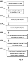
- Fig. 8 presents in general the method according to the present invention.
- the method is utilized for analyzing behavior in an intelligent surveillance system, the system being operable to provide a series of consecutive images 801 of an area under surveillance for consecutive time points.
- a set of points defining at least one moving silhouette on an image.
- position of points in the sets of points on consecutive images are traced in order to generate a plurality of trajectories of points at step 804 for said at least one moving silhouette, each trajectory corresponding to a distinct characteristic point of said silhouette. Exemplary trajectories are shown in Fig.
- the first chart from the top presents positions of points on consecutive frames in Y axis and the second chart presents positions of points on consecutive frames in X axis.
- the bottom chart represents trajectories on both axes, wherein the horizontal axes represent position of points on X, Y axis and the vertical axis represents consecutive frames. Each line corresponds to a trajectory of a different point.
- a reference database of predefined trajectories corresponding to the predefined behaviors so that at step 806 the generated trajectories of points for said at least one moving silhouette can be compared with reference database records.
- the comparison is performed by analyzing the trajectory related to a certain number of previous frames, wherein the number of frames depends on the reference trajectory for a particular type of activity, with which the observer trajectory is compared.
- the comparison is performed by calculating the Euclidean distance for pairs of corresponding points.
- step 807 there is ouptut information regarding the type of predefined behavior to which said moving silhouette corresponds. Such information may be used in order to provide suitable alerts.
- Fig. 9 presents a system according to the present invention.
- the system may be realized using dedicated components or custom made FPGA or ASIC circuits.
- the system comprises a data bus 901 communicatively coupled to a memory 904. Additionally, other components of the system are communicatively coupled to the system bus 901 so that they may be managed by a controller 906.
- An image sequence input module 902 is responsible for providing images data. The images are stored in the memory 904 until a sufficiently long sequence of images may be notified to the controller 906, which shall execute a process of detecting moving objects and silhouette(s) 902 by a specified silhouette detector module 905.
- the system comprises a trajectories generator 907 that based on output from the silhouette detector module 905 defines trajectories of points according to the present invention.
- the system also comprises a reference database 903 for storing previously defined behavior trajectories. Based on data from the trajectories generator 907 and the reference database 903, the comparator and behavior detecor module detects whether the presently analyzed behavior matches at least one of known behaviors. This information may be output externally by an output module.
- the aforementioned method for analyzing human behavior in an intelligent surveillance system may be performed and/or controlled by one or more computer programs.
- Such computer programs are typically executed by utilizing the computing resources in a computing device such as personal computers, personal digital assistants, cellular telephones, receivers and decoders of digital television or similar.
- Applications are stored on a non-transitory medium.
- An example of a non-transitory medium is a non-volatile memory, for example a flash memory or volatile memory, for example RAM.
- the computer instructions are executed by a processor.
- These memories are exemplary recording media for storing computer programs comprising computer-executable instructions performing all the steps of the computer-implemented method according the technical concept presented herein.
Description
- The present invention relates to analysis of human behavior, involving description and identification of actions, in order to automatically recognize behavior type in an intelligent surveillance system.
- There are known a number of approaches to automated behavior analysis systems.
- A US patent
US8131012 presents a method and a system for analyzing and learning behavior based on an acquired stream of video frames. Objects depicted in the stream are determined based on an analysis of the video frames. Each object may have a corresponding search model used to track an object's motion frame-to-frame. Classes of the objects are determined and semantic representations of the objects are generated. - A US patent application
US2003/0107650 discloses a surveillance and security system for automatic detection and warning of detected events, which includes a unit for observing behavior in a predetermined area under surveillance, a unit for processing an output of observed behavior from the unit for observing, and a pattern recognition module for recognizing whether the observed behavior is associated with predefined suspicious behaviors. The pattern recognition module may include infrared heat profiles of persons, images of actual people, sequences of people manipulating shopping bags, sounds of tearing of different types of packaging. The observation of motion, which is related to behavior, is compared against a database of predefined acts. - A US patent
US5666157 presents a surveillance system having at least one primary video camera for translating real images of a zone into electronic video signals at a first level of resolution. The system includes means for sampling movements of an individual or individuals located within the zone from the video signal output from at least one video camera. Video signal of sampled movements of the individual is electronically compared with known characteristics of movements which are indicative of individuals having a criminal intent. - It is the aim of the present invention to provide further improvements to analyzing human behavior in an intelligent surveillance system.
- A US patent application
US2011205359 presents a video surveillance system, which includes a model database storing a plurality of models and a vector database storing a plurality of vectors of recently observed trajectories. The trajectories are built for silhouettes which bound the whole observed object and therefore a single object is described by a single trajectory. - A publication "Synthesis of Silhouettes and Visual Hull Reconstruction for Articulated Humans" by Zhanfeng Yue et al (IEEE Transactions on Multimedia, vol. 10, no. 8, p. 1565-1577, XP011346560) discloses use of an algorithm that generates negative curvature minima of body contours for a surveillance system that detects suspicious behaviour.
- The object of the invention is a system and a method for analyzing behavior in an intelligent surveillance system, according to the appended claims.
- The presented method is particularly useful for automatic recognition of human behavior and can be used in intelligent surveillance systems, including systems having a single stationary camera.
- The method and system are presented by means of example embodiments on a drawing, in which:
-
Fig. 1 illustrates characteristic points, a pose, a trajectory and a descriptor; -
Fig. 2 illustrates an exemplary image of a person with a set of characteristic points; -
Fig. 3 shows an example of an NCM point; -
Fig. 4 presents a third points selection method; -
Fig. 5 presents a fourth points selection method; -
Fig. 6 shows an exemplary outline for defining PCM points; -
Fig. 7 presents exemplary trajectories of moving objects; and -
Fig. 8 presents a top level method according to the present invention. -
Fig. 9 presents a system according to the present invention. - Some portions of the detailed description which follows are presented in terms of data processing procedures, steps or other symbolic representations of operations on data bits that can be performed on computer memory. Therefore, a computer executes such logical steps thus requiring physical manipulations of physical quantities.
- Usually these quantities take the form of electrical or magnetic signals capable of being stored, transferred, combined, compared, and otherwise manipulated in a computer system. For reasons of common usage, these signals are referred to as bits, packets, messages, values, elements, symbols, characters, terms, numbers, or similar.
- Additionally, all of these and similar terms are to be associated with the appropriate physical quantities and are merely convenient labels applied to these quantities. Terms such as "processing" or "creating" or "transferring" or "executing" or "determining" or "detecting" or "obtaining" or "selecting" or "calculating" or "generating" or similar, refer to the action and processes of a computer system that manipulates and transforms data represented as physical (electronic) quantities within the computer's registers and memories into other data similarly represented as physical quantities within the memories or registers or other such information storage.
- The behavior of a person can be described by a set of trajectories of characteristic points of the person, as shown in
Fig. 1 . A set of characteristic points at a given time defines a pose. A set of poses defined for consecutive time points or a set of time vectors for individual points forms a descriptor. - The set of points to define a pose may have a different configuration for different types of behavior to be detected. In other words, for at least one type of behavior, a set of points is generated having a configuration different than a set of points for another type of behavior. For example:
- In order to detect low complexity behaviors, such as simple arm wave gestures, the person may be characterized by three points, i.e. one point located at the head and two points located at the feet or one point located at the head and two points located at the palms,
- In order to detect medium complexity behaviors, such as calling for help, the person may be characterized by five points, i.e. one point located at the head, two points located at the feet and two points located at the palms, as shown in the example of
Fig. 1 , - In order to detect high complexity behaviors, such as dancing or more complex motions, where elbows and knees make significant maneuvers, the person may be characterized by seven points, i.e. one point located at the head, two points located at the feet, two points located at the palms, and two points located at the elbows.
- It shall be noted that the sets of points defined above are an example only and are non-limiting. Other pose-defining points and/or their combinations or numbers are possible without departing from the presented idea.
- For consecutive frames, the positions of points belonging to the set are traced to form trajectories of points.
- There are different ways of describing shapes in images. The present invention is based on the contours of objects in the scene, which are well characterized using the so-called concavity minima or negative curvature minima (NCM) points. These points may be used, inter alia, to recognize persons in video sequences, as described in article "Dressed Human Modeling, Detection and Parts Localization" by Zhao, L., Carnegie Mellon University Pittsburg (2001). The definition of minimum concavity is as follows: an NCM point is a point of the contour between the points (P1, P2 in
Fig. 3 ) of a convex contour, for which the distance from the segment |P1P2| is largest. The points P1 and P2 are suitably distant from each other which will be described in details in the subsequent sections of the present description.Fig. 3 shows an example of anNCM point 301. - Like the concavity minima, contour convexity may be used to describe the curvature. The method utilizing contour convexity is called positive curvature maxima (PCM) points. This time, the extreme points P1 and P2 in
Fig. 3 are selected from the convex contour so that P1 is the point closing the i-th concavity and P2 is a point opening the i+1-th concavity.Fig. 2 shows an example of aPCM point 201. Among so selected pair of points, from the contour a PCM point is selected so that the distance from the segment |P1 P2| is as high as possible. - There are possible different methods for determining the characteristic points.
- The first method, according to one example embodiment of the present invention, is called "Midpoint and four extreme points". This is well suited for detecting behavior, in which human limbs are widely positioned, for example, while waving person's arms or crying for help.
- The method sets four points {A, B, C, D}, wherein the Euclidean distance from the geometric center of the contour P is the greatest. These points are computed, one in each quadrant of the coordinate system having a center located at point P, by the formula:


- Ax,Ay - coordinates x and y of the calculated point,
- w - contour's width on 0X axis,
- h - contour's height on 0Y axis,
- Px, Py- coordinates x and y of the contour's central point,
-

- Another example method, also utilizing the concept of the "Midpoint and four extreme points", applies a different normalization process. The method differs from the previous one in that it applies normalization of x coordinates, calculated according to the formula:

- A third method is called "Points evenly spread on the contour". The method of points selection is based on selection of evenly spread, arbitrary number of points from the contour typically of a silhouette). Such approach allows for gradual selection of the level of contour mapping. The method has been depicted in
Fig. 4 , wherein the following references refer to: - Step - step of selection of consecutive points;
- Buff - a buffer storing reminder of a division in order to minimize an error caused by calculations on integer numbers. It is a case when the Step is not an integer;
- rest(IPktKont/IPkt) - a function calculating a reminder of a division.
- The selected contour points define a descriptor of the contour (typically of a silhouette of a person) in a given video frame and are buffered in an output vector as shown in
Fig. 4 . - More specifically, the procedure in
Fig. 4 starts fromstep 401, where the Step variable is set a value of IPktKont/IPkt, wherein IPkt denotes chosen number of equally distant points on object contour and IPktKont denotes a total number of points in object contour, the Buff variable is set to rest(IPktKont / IPkt) and the 'i' variable is set to 0. Next, atstep 402, it is verified whether the value of the Buff variable is less than 1. In case it is not, atstep 403 the value of Buff variable is decreased by 1.0 before moving to step 404. Otherwise, atstep 404, the value of the Buff variable is increased by the rest of the quotient (IPktKont/IPkt). Subsequently, atstep 405, the i-th point of the contour is added to an output vector as a selected point. Next, atstep 406, the variable 'i' is set to a value of Step + Buff. Atstep 407 it is verified whether 'i' is lower that IPktKont and in case it is the process returns to step 401 in order to process the next point or otherwise the procedure ends atstep 408. - The fourth example method is based on NCM points and PCM points and has been depicted in
Fig. 5 . Because of such combination it is possible to describe silhouettes with data defining curvature of the contour - NCM for negative curvature minima and PCM for positive curvature maxima. - A procedure for determining NCM points starts from
step 501 with selecting a pair of consecutive points {A, B} in a vector of a convex contour. If a complete vector of the convex contour has been analyzed, the procedure proceeds fromstep 502 to step 508. If not, then instep 503 there is determined a length of a segment "a" between the points {A, B}. Next, atstep 504, it is verified whether the length "a" is greater than a threshold. In case the length "a" is greater than the threshold, the procedure proceeds to step 505. Otherwise the procedure returns to step 501 in order to select another pair of points. Atstep 505, there is selected a point C from the convex contour vector such that point C is between points A and B and such that its distance h from the segment "a" is the greatest. - At
step 506 it is verified whether an update contour condition is fulfilled, so that point C may be added to the convex contour. The parameters of the condition are as follows: AHthreshold is a concavity depth threshold, concaveArea is an area of concavity defined by the section of the contour between A and B points, contourArea is an inner area of the currently analyzed contour and the Areathreshold is a threshold defining minimum ratio of concavity area to the inner area of the currently analyzed contour. - If the condition is fulfilled the procedure moves to step 507 where point C is added to the NCM output vector and the process returns to step 501.
- In case, at
step 508, the number of iterations has not reached a required count, the process returns to step 501 and selects another pair of points from the vector of convex contour. The process is repeated from the beginning. - The aforementioned update contour method utilizes a known algorithm, such as "Gift wrapping" or "Jarvis march". Its task is to include in the convex contour a previously selected NCM point so that its definition is maintained. During execution of this method there is added a minimum number of contour points to the contour such that the contour vector maintains its continuity.
- The other part of the fourth method relates to the PCM points that are determined similarly to the NCM points. The method may also be applied to pairs of points of a convex contour and is executed as follows. First there are selected pairs of points {lefti, righti} until a pair fulfilling the condition of
step 504 is obtained, thereby obtaining {lefti, righti} pair shown inFig.6 as element (a). There is also stored an index of a point right0 in the contour vector as idxLeft. - The second step is to move the {lefti, righti} until a next pair is found that fulfils the NCM condition thereby arriving at {left1, right1} shown in
Fig. 6 variant (b). The index of left1 in the contour vector is stored as idxRight. - The third step of the procedure is to select a point K0 from the convex contour between idxLeft and idxRight, for which the distance h0 from the segment |right0left1| is the greatest.
- Lastly, as the fourth step set the idxLeft = idx(right1) and continue from the second step.
- The subsequent Ki points are computed in an analogous way by maximizing their corresponding distances hi from the segments |rightilefti+1|.The process executes its last iteration when leftn = left0. The vector of calculated points is added to previously determined NCM points thereby creating a pose descriptor.
-
Fig. 8 presents in general the method according to the present invention. The method is utilized for analyzing behavior in an intelligent surveillance system, the system being operable to provide a series ofconsecutive images 801 of an area under surveillance for consecutive time points. Atstep 802, for each image of the series, there is generated a set of points defining at least one moving silhouette on an image. Subsequently, atstep 803, position of points in the sets of points on consecutive images are traced in order to generate a plurality of trajectories of points atstep 804 for said at least one moving silhouette, each trajectory corresponding to a distinct characteristic point of said silhouette. Exemplary trajectories are shown inFig. 7 , wherein the first chart from the top presents positions of points on consecutive frames in Y axis and the second chart presents positions of points on consecutive frames in X axis. The bottom chart represents trajectories on both axes, wherein the horizontal axes represent position of points on X, Y axis and the vertical axis represents consecutive frames. Each line corresponds to a trajectory of a different point. Next, atstep 805, there is provided a reference database of predefined trajectories corresponding to the predefined behaviors, so that atstep 806 the generated trajectories of points for said at least one moving silhouette can be compared with reference database records. The comparison is performed by analyzing the trajectory related to a certain number of previous frames, wherein the number of frames depends on the reference trajectory for a particular type of activity, with which the observer trajectory is compared. - The comparison is performed by calculating the Euclidean distance for pairs of corresponding points. Each trajectory shall fit within a predetermined range. For example, assuming that 4 points of a person are traced (e.g. two palms and two feet), the characteristic point designated as the right palm must, for each frame, be located in a distance D not larger than δ from the reference "right hand" for each behavior, namely:


- Finally, at
step 807, there is ouptut information regarding the type of predefined behavior to which said moving silhouette corresponds. Such information may be used in order to provide suitable alerts. -
Fig. 9 presents a system according to the present invention. The system may be realized using dedicated components or custom made FPGA or ASIC circuits. The system comprises a data bus 901 communicatively coupled to a memory 904. Additionally, other components of the system are communicatively coupled to the system bus 901 so that they may be managed by a controller 906. An image sequence input module 902 is responsible for providing images data. The images are stored in the memory 904 until a sufficiently long sequence of images may be notified to the controller 906, which shall execute a process of detecting moving objects and silhouette(s) 902 by a specified silhouette detector module 905. - Furthermore, the system comprises a trajectories generator 907 that based on output from the silhouette detector module 905 defines trajectories of points according to the present invention. The system also comprises a reference database 903 for storing previously defined behavior trajectories. Based on data from the trajectories generator 907 and the reference database 903, the comparator and behavior detecor module detects whether the presently analyzed behavior matches at least one of known behaviors. This information may be output externally by an output module.
- It can be easily recognized, by one skilled in the art, that the aforementioned method for analyzing human behavior in an intelligent surveillance system may be performed and/or controlled by one or more computer programs. Such computer programs are typically executed by utilizing the computing resources in a computing device such as personal computers, personal digital assistants, cellular telephones, receivers and decoders of digital television or similar. Applications are stored on a non-transitory medium. An example of a non-transitory medium is a non-volatile memory, for example a flash memory or volatile memory, for example RAM. The computer instructions are executed by a processor. These memories are exemplary recording media for storing computer programs comprising computer-executable instructions performing all the steps of the computer-implemented method according the technical concept presented herein.
- While the invention presented herein has been depicted, described, and has been defined with reference to particular preferred embodiments, such references and examples of implementation in the foregoing specification do not imply any limitation on the invention. It will, however, be evident that various modifications and changes may be made thereto without departing from the broader scope of the technical concept. The presented preferred embodiments are exemplary only, and are not exhaustive of the scope of the technical concept presented herein.
- Accordingly, the scope of protection is not limited to the preferred embodiments described in the specification, but is only limited by the claims that follow.
Claims (8)
- A method for analyzing behavior in an intelligent surveillance system, the system being operable to provide a series of consecutive images of an area under surveillance for consecutive time points (801), the method comprising the steps of:- for each image of the series, generating a set of points defining at least one moving silhouette (802) on an image;- tracing the position of points in the sets of points (803) on consecutive images in order to generate a trajectory (804);characterized by:- generating a plurality of trajectories of points for said at least one moving silhouette, each trajectory corresponding to a distinct characteristic point of said silhouette (804),- providing a reference database of predefined trajectories corresponding to predefined behaviors (805);- comparing said generated plurality of trajectories of said at least one moving silhouette with said reference database (806);- outputting (807) information regarding the type of the predefined behavior to which said at least one moving silhouette corresponds.
- The method according to claim 1, wherein to detect at least one type of behavior, a set of points is generated having a configuration different than a set of points for another type of behavior.
- The method according to claim 1, wherein said step of generating a set of points defining at least one moving silhouette (802) on an image comprises generating negative curvature minima.
- The method according to claim 1, wherein said step of generating a set of points defining at least one moving silhouette (802) on an image comprises generating positive curvature maxima.
- The method according to claim 1, wherein said step of generating a set of points defining at least one moving silhouette (802) on an image comprises generating negative curvature minima and positive curvature maxima.
- A computer program comprising program code means for performing all the steps of the computer-implemented method according to any of claims 1 to 5 when said program is run on a computer.
- A computer readable medium storing computer-executable instructions performing all the steps of the computer-implemented method according to any of claims 1 to 5 when executed on a computer.
- A system for analyzing behavior in an intelligent surveillance system, the system comprising an image sequence input module (902) configured to provide a series of consecutive images of an area under surveillance for consecutive time points (801), the system further comprising:- a silhouette detector (905) configured to generate, for each image of the series, a set of points defining at least one moving silhouette (802) on an image;- a trajectories generator (907) configured to trace the position of points in the sets ofcharacterized in that:
points (803) on consecutive images in order to generate a trajectory (804);- the trajectories generator (907) is configured to generate (804) a plurality of trajectories of points for said at least one moving silhouette, each trajectory corresponding to a distinct characteristic point of said silhouette;- the system further comprises a reference database (903) configured to store (805) predefined trajectories corresponding to predefined behaviors;- a comparator and behavior detector (908) configured to compare (806) said generated plurality of trajectories of said at least one moving silhouette with said reference database (903);- an output module configured to output (807) information regarding the type of the predefined behavior to which said at least one moving silhouette corresponds.
Priority Applications (1)
| Application Number | Priority Date | Filing Date | Title |
|---|---|---|---|
| PL14160409T PL2899706T3 (en) | 2014-01-28 | 2014-03-18 | Method and system for analyzing human behavior in an intelligent surveillance system |
Applications Claiming Priority (1)
| Application Number | Priority Date | Filing Date | Title |
|---|---|---|---|
| PL406971A PL406971A1 (en) | 2014-01-28 | 2014-01-28 | Method for analyzing of people behaviour in the intelligent monitoring system and the intelligent system of monitoring |
Publications (3)
| Publication Number | Publication Date |
|---|---|
| EP2899706A1 EP2899706A1 (en) | 2015-07-29 |
| EP2899706B1 EP2899706B1 (en) | 2016-12-07 |
| EP2899706B9 true EP2899706B9 (en) | 2017-03-22 |
Family
ID=50287971
Family Applications (1)
| Application Number | Title | Priority Date | Filing Date |
|---|---|---|---|
| EP14160409.0A Not-in-force EP2899706B9 (en) | 2014-01-28 | 2014-03-18 | Method and system for analyzing human behavior in an intelligent surveillance system |
Country Status (3)
| Country | Link |
|---|---|
| US (1) | US20150213308A1 (en) |
| EP (1) | EP2899706B9 (en) |
| PL (2) | PL406971A1 (en) |
Families Citing this family (6)
| Publication number | Priority date | Publication date | Assignee | Title |
|---|---|---|---|---|
| EP3557549B1 (en) | 2018-04-19 | 2024-02-21 | PKE Holding AG | Method for evaluating a motion event |
| CN109508684B (en) * | 2018-11-21 | 2022-12-27 | 中山大学 | Method for recognizing human behavior in video |
| WO2020112920A1 (en) * | 2018-11-26 | 2020-06-04 | Jfm International Corp. | Systems and methods for theft prevention and detection |
| CN109508698B (en) * | 2018-12-19 | 2023-01-10 | 中山大学 | Human behavior recognition method based on binary tree |
| GB2602248A (en) * | 2020-11-11 | 2022-06-29 | 3D4Medical Ltd | Motion assessment instrument |
| WO2023224251A1 (en) * | 2022-05-16 | 2023-11-23 | Samsung Electronics Co., Ltd. | Systems and methods for recognizing non-line-of-sight human actions |
Family Cites Families (10)
| Publication number | Priority date | Publication date | Assignee | Title |
|---|---|---|---|---|
| US5666157A (en) | 1995-01-03 | 1997-09-09 | Arc Incorporated | Abnormality detection and surveillance system |
| US20030107650A1 (en) | 2001-12-11 | 2003-06-12 | Koninklijke Philips Electronics N.V. | Surveillance system with suspicious behavior detection |
| US9036902B2 (en) * | 2007-01-29 | 2015-05-19 | Intellivision Technologies Corporation | Detector for chemical, biological and/or radiological attacks |
| NZ578752A (en) | 2007-02-08 | 2012-03-30 | Behavioral Recognition Sys Inc | Behavioral recognition system |
| US8396247B2 (en) * | 2008-07-31 | 2013-03-12 | Microsoft Corporation | Recognizing actions of animate objects in video |
| US8428311B2 (en) * | 2009-02-25 | 2013-04-23 | Honda Motor Co., Ltd. | Capturing and recognizing hand postures using inner distance shape contexts |
| US8755569B2 (en) * | 2009-05-29 | 2014-06-17 | University Of Central Florida Research Foundation, Inc. | Methods for recognizing pose and action of articulated objects with collection of planes in motion |
| US8462987B2 (en) * | 2009-06-23 | 2013-06-11 | Ut-Battelle, Llc | Detecting multiple moving objects in crowded environments with coherent motion regions |
| US20110054870A1 (en) * | 2009-09-02 | 2011-03-03 | Honda Motor Co., Ltd. | Vision Based Human Activity Recognition and Monitoring System for Guided Virtual Rehabilitation |
| US20110205359A1 (en) * | 2010-02-19 | 2011-08-25 | Panasonic Corporation | Video surveillance system |
-
2014
- 2014-01-28 PL PL406971A patent/PL406971A1/en unknown
- 2014-03-17 US US14/215,101 patent/US20150213308A1/en not_active Abandoned
- 2014-03-18 PL PL14160409T patent/PL2899706T3/en unknown
- 2014-03-18 EP EP14160409.0A patent/EP2899706B9/en not_active Not-in-force
Also Published As
| Publication number | Publication date |
|---|---|
| EP2899706B1 (en) | 2016-12-07 |
| EP2899706A1 (en) | 2015-07-29 |
| PL2899706T3 (en) | 2017-06-30 |
| US20150213308A1 (en) | 2015-07-30 |
| PL406971A1 (en) | 2015-08-03 |
Similar Documents
| Publication | Publication Date | Title |
|---|---|---|
| JP6625220B2 (en) | Method and system for detecting the action of an object in a scene | |
| Ramesh et al. | Dart: distribution aware retinal transform for event-based cameras | |
| EP2899706B9 (en) | Method and system for analyzing human behavior in an intelligent surveillance system | |
| JP5647155B2 (en) | Body feature detection and human pose estimation using inner distance shape relation | |
| JP4686663B2 (en) | Pedestrian tracking method and pedestrian tracking device | |
| JP4708422B2 (en) | Tracking of two-hand movement | |
| Wang et al. | Hidden-markov-models-based dynamic hand gesture recognition | |
| WO2010080949A1 (en) | Controlled human pose estimation from depth image streams | |
| EP2930690B1 (en) | Apparatus and method for analyzing a trajectory | |
| CN110633004A (en) | Interaction method, device and system based on human body posture estimation | |
| US9256945B2 (en) | System for tracking a moving object, and a method and a non-transitory computer readable medium thereof | |
| KR102371127B1 (en) | Gesture Recognition Method and Processing System using Skeleton Length Information | |
| KR101350387B1 (en) | Method for detecting hand using depth information and apparatus thereof | |
| Mo et al. | Human Behavior Analysis Using Multiple 2D Features and Multicategory Support Vector Machine. | |
| Kumar | Motion trajectory based human face and hands tracking for sign language recognition | |
| JP2011232845A (en) | Feature point extracting device and method | |
| Kawashima et al. | Adaptive template method for early recognition of gestures | |
| CN110826495A (en) | Body left and right limb consistency tracking and distinguishing method and system based on face orientation | |
| Springstübe et al. | Continuous convolutional object tracking. | |
| JP2021077177A (en) | Operation recognition apparatus, operation recognition method, and operation recognition program | |
| Zhou et al. | A Novel Algorithm of Edge Location Based on Omni-directional and Multi-scale MM. | |
| KR102540560B1 (en) | Hierarchical estimation method for hand poses using random decision forests, recording medium and device for performing the method | |
| Rett et al. | Laban movement analysis for multi-ocular systems | |
| Kawana et al. | Occluded Appearance Modeling with Sample Weighting for Human Pose Estimation | |
| Sharifi et al. | Marker based human pose estimation using annealed particle swarm optimization with search space partitioning |
Legal Events
| Date | Code | Title | Description |
|---|---|---|---|
| PUAI | Public reference made under article 153(3) epc to a published international application that has entered the european phase |
Free format text: ORIGINAL CODE: 0009012 |
|
| 17P | Request for examination filed |
Effective date: 20140318 |
|
| AK | Designated contracting states |
Kind code of ref document: A1 Designated state(s): AL AT BE BG CH CY CZ DE DK EE ES FI FR GB GR HR HU IE IS IT LI LT LU LV MC MK MT NL NO PL PT RO RS SE SI SK SM TR |
|
| AX | Request for extension of the european patent |
Extension state: BA ME |
|
| 17P | Request for examination filed |
Effective date: 20140319 |
|
| 17Q | First examination report despatched |
Effective date: 20160523 |
|
| RIC1 | Information provided on ipc code assigned before grant |
Ipc: G08B 13/196 20060101AFI20160824BHEP Ipc: G06K 9/00 20060101ALI20160824BHEP Ipc: G06T 7/20 20060101ALI20160824BHEP |
|
| GRAP | Despatch of communication of intention to grant a patent |
Free format text: ORIGINAL CODE: EPIDOSNIGR1 |
|
| GRAS | Grant fee paid |
Free format text: ORIGINAL CODE: EPIDOSNIGR3 |
|
| INTG | Intention to grant announced |
Effective date: 20161005 |
|
| GRAA | (expected) grant |
Free format text: ORIGINAL CODE: 0009210 |
|
| AK | Designated contracting states |
Kind code of ref document: B1 Designated state(s): AL AT BE BG CH CY CZ DE DK EE ES FI FR GB GR HR HU IE IS IT LI LT LU LV MC MK MT NL NO PL PT RO RS SE SI SK SM TR |
|
| REG | Reference to a national code |
Ref country code: GB Ref legal event code: FG4D |
|
| REG | Reference to a national code |
Ref country code: CH Ref legal event code: EP Ref country code: AT Ref legal event code: REF Ref document number: 852328 Country of ref document: AT Kind code of ref document: T Effective date: 20161215 |
|
| REG | Reference to a national code |
Ref country code: IE Ref legal event code: FG4D |
|
| REG | Reference to a national code |
Ref country code: DE Ref legal event code: R096 Ref document number: 602014005268 Country of ref document: DE |
|
| GRAT | Correction requested after decision to grant or after decision to maintain patent in amended form |
Free format text: ORIGINAL CODE: EPIDOSNCDEC |
|
| PG25 | Lapsed in a contracting state [announced via postgrant information from national office to epo] |
Ref country code: LV Free format text: LAPSE BECAUSE OF FAILURE TO SUBMIT A TRANSLATION OF THE DESCRIPTION OR TO PAY THE FEE WITHIN THE PRESCRIBED TIME-LIMIT Effective date: 20161207 |
|
| REG | Reference to a national code |
Ref country code: LT Ref legal event code: MG4D |
|
| REG | Reference to a national code |
Ref country code: NL Ref legal event code: MP Effective date: 20161207 |
|
| PG25 | Lapsed in a contracting state [announced via postgrant information from national office to epo] |
Ref country code: GR Free format text: LAPSE BECAUSE OF FAILURE TO SUBMIT A TRANSLATION OF THE DESCRIPTION OR TO PAY THE FEE WITHIN THE PRESCRIBED TIME-LIMIT Effective date: 20170308 Ref country code: LT Free format text: LAPSE BECAUSE OF FAILURE TO SUBMIT A TRANSLATION OF THE DESCRIPTION OR TO PAY THE FEE WITHIN THE PRESCRIBED TIME-LIMIT Effective date: 20161207 Ref country code: NO Free format text: LAPSE BECAUSE OF FAILURE TO SUBMIT A TRANSLATION OF THE DESCRIPTION OR TO PAY THE FEE WITHIN THE PRESCRIBED TIME-LIMIT Effective date: 20170307 Ref country code: SE Free format text: LAPSE BECAUSE OF FAILURE TO SUBMIT A TRANSLATION OF THE DESCRIPTION OR TO PAY THE FEE WITHIN THE PRESCRIBED TIME-LIMIT Effective date: 20161207 |
|
| REG | Reference to a national code |
Ref country code: AT Ref legal event code: MK05 Ref document number: 852328 Country of ref document: AT Kind code of ref document: T Effective date: 20161207 |
|
| PG25 | Lapsed in a contracting state [announced via postgrant information from national office to epo] |
Ref country code: FI Free format text: LAPSE BECAUSE OF FAILURE TO SUBMIT A TRANSLATION OF THE DESCRIPTION OR TO PAY THE FEE WITHIN THE PRESCRIBED TIME-LIMIT Effective date: 20161207 Ref country code: HR Free format text: LAPSE BECAUSE OF FAILURE TO SUBMIT A TRANSLATION OF THE DESCRIPTION OR TO PAY THE FEE WITHIN THE PRESCRIBED TIME-LIMIT Effective date: 20161207 Ref country code: RS Free format text: LAPSE BECAUSE OF FAILURE TO SUBMIT A TRANSLATION OF THE DESCRIPTION OR TO PAY THE FEE WITHIN THE PRESCRIBED TIME-LIMIT Effective date: 20161207 Ref country code: ES Free format text: LAPSE BECAUSE OF FAILURE TO SUBMIT A TRANSLATION OF THE DESCRIPTION OR TO PAY THE FEE WITHIN THE PRESCRIBED TIME-LIMIT Effective date: 20161207 |
|
| PG25 | Lapsed in a contracting state [announced via postgrant information from national office to epo] |
Ref country code: NL Free format text: LAPSE BECAUSE OF FAILURE TO SUBMIT A TRANSLATION OF THE DESCRIPTION OR TO PAY THE FEE WITHIN THE PRESCRIBED TIME-LIMIT Effective date: 20161207 |
|
| PG25 | Lapsed in a contracting state [announced via postgrant information from national office to epo] |
Ref country code: SK Free format text: LAPSE BECAUSE OF FAILURE TO SUBMIT A TRANSLATION OF THE DESCRIPTION OR TO PAY THE FEE WITHIN THE PRESCRIBED TIME-LIMIT Effective date: 20161207 Ref country code: CZ Free format text: LAPSE BECAUSE OF FAILURE TO SUBMIT A TRANSLATION OF THE DESCRIPTION OR TO PAY THE FEE WITHIN THE PRESCRIBED TIME-LIMIT Effective date: 20161207 Ref country code: IS Free format text: LAPSE BECAUSE OF FAILURE TO SUBMIT A TRANSLATION OF THE DESCRIPTION OR TO PAY THE FEE WITHIN THE PRESCRIBED TIME-LIMIT Effective date: 20170407 Ref country code: RO Free format text: LAPSE BECAUSE OF FAILURE TO SUBMIT A TRANSLATION OF THE DESCRIPTION OR TO PAY THE FEE WITHIN THE PRESCRIBED TIME-LIMIT Effective date: 20161207 Ref country code: EE Free format text: LAPSE BECAUSE OF FAILURE TO SUBMIT A TRANSLATION OF THE DESCRIPTION OR TO PAY THE FEE WITHIN THE PRESCRIBED TIME-LIMIT Effective date: 20161207 |
|
| PG25 | Lapsed in a contracting state [announced via postgrant information from national office to epo] |
Ref country code: BG Free format text: LAPSE BECAUSE OF FAILURE TO SUBMIT A TRANSLATION OF THE DESCRIPTION OR TO PAY THE FEE WITHIN THE PRESCRIBED TIME-LIMIT Effective date: 20170307 Ref country code: BE Free format text: LAPSE BECAUSE OF FAILURE TO SUBMIT A TRANSLATION OF THE DESCRIPTION OR TO PAY THE FEE WITHIN THE PRESCRIBED TIME-LIMIT Effective date: 20161207 Ref country code: SM Free format text: LAPSE BECAUSE OF FAILURE TO SUBMIT A TRANSLATION OF THE DESCRIPTION OR TO PAY THE FEE WITHIN THE PRESCRIBED TIME-LIMIT Effective date: 20161207 Ref country code: PT Free format text: LAPSE BECAUSE OF FAILURE TO SUBMIT A TRANSLATION OF THE DESCRIPTION OR TO PAY THE FEE WITHIN THE PRESCRIBED TIME-LIMIT Effective date: 20170407 Ref country code: IT Free format text: LAPSE BECAUSE OF FAILURE TO SUBMIT A TRANSLATION OF THE DESCRIPTION OR TO PAY THE FEE WITHIN THE PRESCRIBED TIME-LIMIT Effective date: 20161207 Ref country code: AT Free format text: LAPSE BECAUSE OF FAILURE TO SUBMIT A TRANSLATION OF THE DESCRIPTION OR TO PAY THE FEE WITHIN THE PRESCRIBED TIME-LIMIT Effective date: 20161207 |
|
| REG | Reference to a national code |
Ref country code: DE Ref legal event code: R097 Ref document number: 602014005268 Country of ref document: DE |
|
| PLBE | No opposition filed within time limit |
Free format text: ORIGINAL CODE: 0009261 |
|
| STAA | Information on the status of an ep patent application or granted ep patent |
Free format text: STATUS: NO OPPOSITION FILED WITHIN TIME LIMIT |
|
| REG | Reference to a national code |
Ref country code: CH Ref legal event code: PL |
|
| 26N | No opposition filed |
Effective date: 20170908 |
|
| PG25 | Lapsed in a contracting state [announced via postgrant information from national office to epo] |
Ref country code: DK Free format text: LAPSE BECAUSE OF FAILURE TO SUBMIT A TRANSLATION OF THE DESCRIPTION OR TO PAY THE FEE WITHIN THE PRESCRIBED TIME-LIMIT Effective date: 20161207 Ref country code: MC Free format text: LAPSE BECAUSE OF FAILURE TO SUBMIT A TRANSLATION OF THE DESCRIPTION OR TO PAY THE FEE WITHIN THE PRESCRIBED TIME-LIMIT Effective date: 20161207 Ref country code: SI Free format text: LAPSE BECAUSE OF FAILURE TO SUBMIT A TRANSLATION OF THE DESCRIPTION OR TO PAY THE FEE WITHIN THE PRESCRIBED TIME-LIMIT Effective date: 20161207 |
|
| REG | Reference to a national code |
Ref country code: IE Ref legal event code: MM4A |
|
| REG | Reference to a national code |
Ref country code: FR Ref legal event code: ST Effective date: 20171130 |
|
| PG25 | Lapsed in a contracting state [announced via postgrant information from national office to epo] |
Ref country code: LU Free format text: LAPSE BECAUSE OF NON-PAYMENT OF DUE FEES Effective date: 20170318 Ref country code: FR Free format text: LAPSE BECAUSE OF NON-PAYMENT OF DUE FEES Effective date: 20170331 |
|
| PG25 | Lapsed in a contracting state [announced via postgrant information from national office to epo] |
Ref country code: CH Free format text: LAPSE BECAUSE OF NON-PAYMENT OF DUE FEES Effective date: 20170331 Ref country code: LI Free format text: LAPSE BECAUSE OF NON-PAYMENT OF DUE FEES Effective date: 20170331 Ref country code: IE Free format text: LAPSE BECAUSE OF NON-PAYMENT OF DUE FEES Effective date: 20170318 |
|
| PG25 | Lapsed in a contracting state [announced via postgrant information from national office to epo] |
Ref country code: MT Free format text: LAPSE BECAUSE OF NON-PAYMENT OF DUE FEES Effective date: 20170318 |
|
| PG25 | Lapsed in a contracting state [announced via postgrant information from national office to epo] |
Ref country code: HU Free format text: LAPSE BECAUSE OF FAILURE TO SUBMIT A TRANSLATION OF THE DESCRIPTION OR TO PAY THE FEE WITHIN THE PRESCRIBED TIME-LIMIT; INVALID AB INITIO Effective date: 20140318 |
|
| PG25 | Lapsed in a contracting state [announced via postgrant information from national office to epo] |
Ref country code: CY Free format text: LAPSE BECAUSE OF FAILURE TO SUBMIT A TRANSLATION OF THE DESCRIPTION OR TO PAY THE FEE WITHIN THE PRESCRIBED TIME-LIMIT Effective date: 20161207 |
|
| PG25 | Lapsed in a contracting state [announced via postgrant information from national office to epo] |
Ref country code: MK Free format text: LAPSE BECAUSE OF FAILURE TO SUBMIT A TRANSLATION OF THE DESCRIPTION OR TO PAY THE FEE WITHIN THE PRESCRIBED TIME-LIMIT Effective date: 20161207 |
|
| PG25 | Lapsed in a contracting state [announced via postgrant information from national office to epo] |
Ref country code: TR Free format text: LAPSE BECAUSE OF FAILURE TO SUBMIT A TRANSLATION OF THE DESCRIPTION OR TO PAY THE FEE WITHIN THE PRESCRIBED TIME-LIMIT Effective date: 20161207 |
|
| PGFP | Annual fee paid to national office [announced via postgrant information from national office to epo] |
Ref country code: GB Payment date: 20200327 Year of fee payment: 7 Ref country code: DE Payment date: 20200317 Year of fee payment: 7 |
|
| PG25 | Lapsed in a contracting state [announced via postgrant information from national office to epo] |
Ref country code: AL Free format text: LAPSE BECAUSE OF FAILURE TO SUBMIT A TRANSLATION OF THE DESCRIPTION OR TO PAY THE FEE WITHIN THE PRESCRIBED TIME-LIMIT Effective date: 20161207 |
|
| PGFP | Annual fee paid to national office [announced via postgrant information from national office to epo] |
Ref country code: PL Payment date: 20200312 Year of fee payment: 7 |
|
| REG | Reference to a national code |
Ref country code: DE Ref legal event code: R119 Ref document number: 602014005268 Country of ref document: DE |
|
| GBPC | Gb: european patent ceased through non-payment of renewal fee |
Effective date: 20210318 |
|
| PG25 | Lapsed in a contracting state [announced via postgrant information from national office to epo] |
Ref country code: GB Free format text: LAPSE BECAUSE OF NON-PAYMENT OF DUE FEES Effective date: 20210318 Ref country code: DE Free format text: LAPSE BECAUSE OF NON-PAYMENT OF DUE FEES Effective date: 20211001 |
|
| PG25 | Lapsed in a contracting state [announced via postgrant information from national office to epo] |
Ref country code: PL Free format text: LAPSE BECAUSE OF NON-PAYMENT OF DUE FEES Effective date: 20210318 |