EP2899503B1 - MEMS-Sensor mit Anordnung zur Reduzierung von nichtlinearer Bewegung - Google Patents
MEMS-Sensor mit Anordnung zur Reduzierung von nichtlinearer Bewegung Download PDFInfo
- Publication number
- EP2899503B1 EP2899503B1 EP15152031.9A EP15152031A EP2899503B1 EP 2899503 B1 EP2899503 B1 EP 2899503B1 EP 15152031 A EP15152031 A EP 15152031A EP 2899503 B1 EP2899503 B1 EP 2899503B1
- Authority
- EP
- European Patent Office
- Prior art keywords
- mass
- proof
- travelling
- spring
- motion
- Prior art date
- Legal status (The legal status is an assumption and is not a legal conclusion. Google has not performed a legal analysis and makes no representation as to the accuracy of the status listed.)
- Active
Links
Images


Classifications
-
- G—PHYSICS
- G01—MEASURING; TESTING
- G01C—MEASURING DISTANCES, LEVELS OR BEARINGS; SURVEYING; NAVIGATION; GYROSCOPIC INSTRUMENTS; PHOTOGRAMMETRY OR VIDEOGRAMMETRY
- G01C19/00—Gyroscopes; Turn-sensitive devices using vibrating masses; Turn-sensitive devices without moving masses; Measuring angular rate using gyroscopic effects
- G01C19/56—Turn-sensitive devices using vibrating masses, e.g. vibratory angular rate sensors based on Coriolis forces
- G01C19/5719—Turn-sensitive devices using vibrating masses, e.g. vibratory angular rate sensors based on Coriolis forces using planar vibrating masses driven in a translation vibration along an axis
- G01C19/5733—Structural details or topology
- G01C19/5755—Structural details or topology the devices having a single sensing mass
- G01C19/5762—Structural details or topology the devices having a single sensing mass the sensing mass being connected to a driving mass, e.g. driving frames
-
- G—PHYSICS
- G01—MEASURING; TESTING
- G01C—MEASURING DISTANCES, LEVELS OR BEARINGS; SURVEYING; NAVIGATION; GYROSCOPIC INSTRUMENTS; PHOTOGRAMMETRY OR VIDEOGRAMMETRY
- G01C19/00—Gyroscopes; Turn-sensitive devices using vibrating masses; Turn-sensitive devices without moving masses; Measuring angular rate using gyroscopic effects
- G01C19/56—Turn-sensitive devices using vibrating masses, e.g. vibratory angular rate sensors based on Coriolis forces
- G01C19/5705—Turn-sensitive devices using vibrating masses, e.g. vibratory angular rate sensors based on Coriolis forces using masses driven in reciprocating rotary motion about an axis
- G01C19/5712—Turn-sensitive devices using vibrating masses, e.g. vibratory angular rate sensors based on Coriolis forces using masses driven in reciprocating rotary motion about an axis the devices involving a micromechanical structure
-
- B—PERFORMING OPERATIONS; TRANSPORTING
- B81—MICROSTRUCTURAL TECHNOLOGY
- B81B—MICROSTRUCTURAL DEVICES OR SYSTEMS, e.g. MICROMECHANICAL DEVICES
- B81B3/00—Devices comprising flexible or deformable elements, e.g. comprising elastic tongues or membranes
- B81B3/0035—Constitution or structural means for controlling the movement of the flexible or deformable elements
- B81B3/0051—For defining the movement, i.e. structures that guide or limit the movement of an element
-
- B—PERFORMING OPERATIONS; TRANSPORTING
- B81—MICROSTRUCTURAL TECHNOLOGY
- B81B—MICROSTRUCTURAL DEVICES OR SYSTEMS, e.g. MICROMECHANICAL DEVICES
- B81B7/00—Microstructural systems; Auxiliary parts of microstructural devices or systems
- B81B7/02—Microstructural systems; Auxiliary parts of microstructural devices or systems containing distinct electrical or optical devices of particular relevance for their function, e.g. microelectro-mechanical systems [MEMS]
-
- G—PHYSICS
- G01—MEASURING; TESTING
- G01C—MEASURING DISTANCES, LEVELS OR BEARINGS; SURVEYING; NAVIGATION; GYROSCOPIC INSTRUMENTS; PHOTOGRAMMETRY OR VIDEOGRAMMETRY
- G01C19/00—Gyroscopes; Turn-sensitive devices using vibrating masses; Turn-sensitive devices without moving masses; Measuring angular rate using gyroscopic effects
- G01C19/56—Turn-sensitive devices using vibrating masses, e.g. vibratory angular rate sensors based on Coriolis forces
- G01C19/5719—Turn-sensitive devices using vibrating masses, e.g. vibratory angular rate sensors based on Coriolis forces using planar vibrating masses driven in a translation vibration along an axis
- G01C19/5733—Structural details or topology
- G01C19/574—Structural details or topology the devices having two sensing masses in anti-phase motion
- G01C19/5747—Structural details or topology the devices having two sensing masses in anti-phase motion each sensing mass being connected to a driving mass, e.g. driving frames
-
- G—PHYSICS
- G01—MEASURING; TESTING
- G01P—MEASURING LINEAR OR ANGULAR SPEED, ACCELERATION, DECELERATION, OR SHOCK; INDICATING PRESENCE, ABSENCE, OR DIRECTION, OF MOVEMENT
- G01P15/00—Measuring acceleration; Measuring deceleration; Measuring shock, i.e. sudden change of acceleration
- G01P15/02—Measuring acceleration; Measuring deceleration; Measuring shock, i.e. sudden change of acceleration by making use of inertia forces using solid seismic masses
- G01P15/08—Measuring acceleration; Measuring deceleration; Measuring shock, i.e. sudden change of acceleration by making use of inertia forces using solid seismic masses with conversion into electric or magnetic values
- G01P15/0802—Details
-
- B—PERFORMING OPERATIONS; TRANSPORTING
- B81—MICROSTRUCTURAL TECHNOLOGY
- B81B—MICROSTRUCTURAL DEVICES OR SYSTEMS, e.g. MICROMECHANICAL DEVICES
- B81B2201/00—Specific applications of microelectromechanical systems
- B81B2201/02—Sensors
- B81B2201/0228—Inertial sensors
- B81B2201/0242—Gyroscopes
-
- B—PERFORMING OPERATIONS; TRANSPORTING
- B81—MICROSTRUCTURAL TECHNOLOGY
- B81B—MICROSTRUCTURAL DEVICES OR SYSTEMS, e.g. MICROMECHANICAL DEVICES
- B81B2203/00—Basic microelectromechanical structures
- B81B2203/01—Suspended structures, i.e. structures allowing a movement
- B81B2203/0145—Flexible holders
- B81B2203/0163—Spring holders
Definitions
- the present invention relates generally to angular velocity sensors and more particularly relates to angular velocity sensors that include guided mass systems.
- Vibratory rate gyroscopes broadly function by driving the sensor into a first motion and measuring a second motion of the sensor that is responsive to both the first motion and the angular velocity to be sensed.
- a mass within the sensor is driven into oscillation by an actuator.
- Rotation of the sensor imparts a Coriolis force to the oscillating mass that is proportional to the angular velocity (or rotation rate), and depends on the orientation of the angular velocity vector with respect to the velocity vector of the proof mass.
- the Coriolis force, the angular velocity vector, and the proof-mass velocity vector are mutually orthogonal. For example, a proof-mass moving in an X-direction within a sensor rotating about a Y-axis experiences a Z directed Coriolis force.
- a proof-mass moving in an X-direction within a sensor rotating about a Z-axis experiences a Y directed Coriolis force.
- a proof-mass moving in an X-direction within a sensor rotating about the X-axis experiences no Coriolis force.
- Coriolis forces imparted to the proof-mass are usually sensed indirectly by measuring motions within the sensor that are responsive to the Coriolis forces.
- electrostatic actuators of the parallel-plate type are used to drive the proof-mass out-of-plane.
- the actuators are formed between the proof-mass and the substrate.
- the electrostatic force depends on the gap between the proof-mass and the substrate. Because the proof-mass oscillates out-of-plane, the electrostatic force is nonlinear which tends to limit the device performance. Additionally, the electrostatic force is reduced because of the requirement to have large vertical gaps or a cavity under the proof-mass. Achieving large amplitude oscillation requires large force and that might require high-voltage actuation. Adding high-voltage actuation increases the fabrication cost and complexity of the integrated circuits.
- a conventional multi-axis gyroscope might use multiple structures that oscillate at independent frequencies to sense angular rates. Each structure requires a separate drive circuit to oscillate the respective proof-masses. Having more than one drive circuit increases cost and power consumption.
- US 2005/072231 discloses an oscillatory rate sensor for sensing rotation about the "z-axis". It is tuning-fork in nature with structural linkages and dynamics such that fundamental anti-phase oscillation of two proof masses is accomplished by virtue of the mechanical linkages.
- US 2010/0313657 discloses micromachined tuning fork gyroscopes with ultrahigh sensitivity and shock rejection.
- a vibratory rate z-axis gyroscope is characterized by drive-mode and sense-mode quality factors and rate sensitivity and is fabricated with at least two decoupled vibratory tines and a levered drive-mode mechanism coupled between the tines.
- US 2012/0222483 discloses a spring structure, resonator, resonator array and sensor.
- the document presents a spring structure, which has at least two masses coupled in a first direction as opposite phase oscillators by means of springs connected to them via a loop between said springs connected to their coupling points.
- US 2013/068018 A1 discloses a gyroscope that comprises a substrate and a guided mass system.
- the guided mass system comprises proof-mass and guiding arm.
- the proof-mass and the guiding arm are disposed in a plane parallel to the substrate.
- the proof-mass is coupled to the guiding arm.
- the guiding arm is also coupled to the substrate through a spring.
- the guiding arm allows motion of the proof-mass to a first direction in the plane.
- the guiding arm and the proof-mass rotate about a first sense axis.
- the first sense axis is in the plane and parallel to the first direction.
- the gyroscope includes an actuator for vibrating the proof-mass in the first direction.
- the gyroscope also includes a transducer for sensing motion of the proof-mass-normal to the plane in response to angular velocity about a first input axis that is in the plane and orthogonal to the first direction.
- Embodiments for modifying a spring mass configuration are disclosed that minimize the effects of unwanted nonlinear motion on a Micro-Electro-Mechanical Systems (MEMS) sensor.
- the modifications include any or any combination of providing a rigid element between rotating structures of the spring mass configuration, tuning a spring system between the rotating structures and coupling an electrical cancellation system to the rotating structures. In so doing unwanted nonlinear motion such as unwanted 2 nd harmonic motion is minimized.
- MEMS sensor in an aspect, includes a first and second rotating arm. The first and second rotating arms are coupled to each other and the first and second rotating arms are configured to counter rotate when driven into oscillation.
- the MEMS sensor also includes at least one travelling system. The at least one travelling system is coupled to the first and second rotating arms.
- the MEMS sensor includes at least one actuator for driving the at least one travelling system into oscillation. The at least one travelling system moves in a first direction when driven into oscillation.
- the present invention relates generally to angular velocity sensors and more particularly relates to angular velocity sensors that include guided mass systems.
- the following description is presented to enable one of ordinary skill in the art to make and use the invention and is provided in the context of a patent application and its requirements.
- Various modifications to the preferred embodiments and the generic principles and features described herein will be readily apparent to those skilled in the art.
- the present invention is not intended to be limited to the embodiments shown, but is to be accorded the widest scope consistent with the principles and features described herein.
- MEMS Micro-Electro-Mechanical Systems
- a MEMS device may refer to a semiconductor device implemented as a Microelectromechanical system.
- a MEMS device includes mechanical elements and optionally includes electronics for sensing.
- MEMS devices include but are not limited to gyroscopes, accelerometers, magnetometers, and pressure sensors.
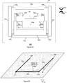
- FIG. 1 illustrates four different spring-mass configurations 10, 11, 12 and 13, that could be utilized in a MEMS sensor, respectively.
- a first spring-mass configuration 10 includes a spring-mass system 10A.
- the spring mass system 10A includes a lever arm 20A, a proof mass 30A, a linear spring 40A, and a hinge 50A attached to a stable point 60A.
- the proof mass, 30A, in the spring mass system 10A has three degrees of freedom.
- the proof mass 30A can rotate by an angle ⁇ about an axis passing from the center of the hinge 50A and normal to a first plane in this embodiment, the XY plane, and it can translate in X and Y direction as it rotates in the X-Y plane.
- hinge 50A has a finite translational compliance
- linear spring 40A has a finite rotational compliance. If it is assumed that the length of the spring 40A is negligible and the length of the lever arm 20A is L.
- ⁇ d which is named as drive frequency
- the drive frequency can be the natural frequency of the spring mass system 10A
- X-direction motion of the proof mass 30A at the drive frequency can be given as: X d ⁇ L ⁇ sin ⁇ d t
- the Y direction motion of the mass 30A is at two times the drive frequency. This behavior is due to the nonlinearity of the rotational movement of the proof mass 30A. If the mass is driven in the X direction with the use of a lever arm 20A at the drive frequency, there is always a Y direction vibration which is at two times the drive frequency, which is referred to as 2 nd Harmonic vibration.
- the 2 nd Harmonic vibration can be non-ideal for MEMS sensors that are driven in one direction and the sensing motion is in-plane and orthogonal to the drive direction.
- the sensing direction is the Y direction
- an erroneous signal in Y direction with a frequency that is two times the drive frequency is generated by the nonlinear motion of the lever arms. So, for those cases, it is needed to eliminate the Y direction component of the nonlinear motion by the use of specific structures and elements which may be added to the spring-mass system 10A.
- FIG. 2A illustrates an embodiment of a single axis gyroscope comprising a guided mass system 500.
- the guided mass system 500 is disposed in an X-Y plane parallel to a substrate 101 and comprises a guided mass system 100 coupled to a yaw proof mass 518a.
- the guided mass system 100 includes guiding arms 104a and 104b that are flexibly coupled via springs 108a and 108b to the substrate 101 via at least one anchoring point 106a.
- the two guiding arms 104a and 104b are flexibly coupled to one proof-mass 102a via springs 103a and 103b.
- the yaw proof mass 518a is flexibly connected to the proof mass 102a via yaw-springs 520a-520d.
- the proof mass 102a and yaw proof mass 518a, guiding arms 104a and 104b, anchoring point 106a, and springs 103a, 103b, 108a, and 108b form a planar four-bar linkage.
- the springs 103a, 103b, 108a, and 108b are compliant in-plane about an axis in the Z-direction so that each guiding arm 104a and 104b can rotate in-plane while the proof-mass 102a translates in an X-direction, as shown in Figure 2B .
- Yaw-springs 520a-520d are stiff in the X-direction such that when the guided mass system 100 translates in the X-direction, the yaw proof-mass 518a also translates with the proof mass 102a.
- Electrostatic actuators such as comb drives 109a and 109b, are connected to the proof mass 102a to drive the guided mass system 100. In this embodiment, two electrostatic actuators are utilized.
- electrostatic actuator can be provided.
- electrostatic actuators will be described throughout this specification as the actuators being used to drive the guided mass systems, one of ordinary skill in the art recognizes that a variety of actuators could be utilized for this function.
- the actuators could be piezoelectric, thermal or electromagnetic or the like.
- the guided mass system 500 can be driven at a drive frequency by a single drive circuit coupled to the actuators 109a and 109b.
- the drive frequency can be a resonant frequency of the guided mass system 500.
- Angular velocity about a yaw-input axis in the Z-direction will cause a Coriolis force to act on the yaw proof-mass 518a in the Y-direction resulting in motion of the yaw proof-mass 518a in the Y-direction.
- a capacitive electrode 522a is used to sense the motion of the yaw proof-mass 518a in the Y-direction which provides a measure of the angular velocity about the yaw-input axis.
- transducers could be utilized in a system and method in accordance with the present invention.
- capacitive electrode 522a instead of using the capacitive electrode 522a, one can also use a piezoelectric or optical or the like transducer and its use would be within the spirit and scope of the present invention.
- the guided mass system 500 can be simply represented by the spring mass system 10A that is shown in Figure 1 .
- the lever arms 104a-104b are similar to the lever arm 20A, the springs 103a-103b, 108a-108b and 520a-520d of the guided mass system 500 are compliant in the Y direction.
- the spring 40A can be a representation of y direction compliance of the springs 103a-103b, 108a-108b and 520a-520d.
- the proof mass 102a and the yaw proof-mass 518a are attached to the springs 103a-103b and 520a-520d, respectively, as the proof mass 30A is attached to the spring 40A.
- in-plane rotational compliance of the springs 108a-108b that are attached to the anchor 106a can be represented by the hinge 50A and the stable point 60A.
- the motion of the center of mass of proof mass 102a has a non-linear motion.
- the proof mass 102a and yaw proof-mass 518a are driven in the X direction, there is also a motion in Y direction that is at two times the drive frequency which is due to the nonlinearity of the drive motion as it has been explained in Figure 1 for the spring-mass configuration 10.
- the motion at two times the drive frequency can also be called the 2 nd harmonic motion of the guided mass system 500.
- the 2 nd Harmonic motion is sensed by the capacitive electrode 522a as an erroneous signal and it may corrupt the readings or saturate the front end electronics.
- guided mass system 500 can also be used as a dual axis gyroscope. If the springs 108a and 108b are compliant about a first roll-sense axis in the X-direction then the guiding arms 104a and 104b can rotate out-of-plane, whereby out-of-plane rotation of the guiding arms 104a and 104b causes the proof mass 102a and the yaw proof mass 518a move out-of-plane with the guiding arms 104a and 104b.
- an angular velocity about a roll-input axis in the Y-direction that is in the plane of the substrate and orthogonal to the X-direction will cause a Coriolis force to act on the proof-mass 102a and the yaw proof-mass 518a in the Z-direction.
- the Coriolis force causes the guided mass system 500 to rotate out-of-plane about the first roll-sense axis.
- the guided mass system 500 rotates out-of-plane
- the guiding arms 104a and 104b and the proof mass 102a and yaw proof mass 518a rotate out-of-plane about the first roll-sense axis.
- the amplitude of the rotation of the guided mass system 500 is proportional to the angular velocity about the roll-input axis.
- a capacitive electrode 112a under the proof mass 102a is used to detect the rotation of the guided mass system 500 about the first roll-sense axis.
- the rotation provides a measure of the angular velocity about the roll-input axis.
- a variety of types of transducers could be utilized in the present invention.
- the capacitive electrode 112a could be also piezoelectric or optical or the like and its use would be within the spirit and scope of the present invention.
- the guided mass system 500 of Figure 2A can be modified to eliminate the 2 nd harmonic motion by using the methods that are introduced in one or more of the spring mass configurations 11, 12 and 13 shown in Figure 1 .
- a second spring-mass configuration 11 is shown in Figure 1 that has components similar to the spring-mass configuration 10.
- Spring mass configuration 11 includes two spring mass systems 11A-11B.
- Each of the two spring mass systems 11A-11B comprise lever arms 21A-21B, and a traveling system 101A comprising traveling masses 31A-31B and connection element 21, linear springs 41A-41B, hinges 51A-51B attached to stable points 61A-61B.
- connection element 21 that connects two spring-mass systems 11A and 11B.
- connection element 21 that connects two spring-mass systems 11A and 11B.
- both 11A and 11B move in the same X direction during the drive operation. But, the Y direction motion of 11A and 11B are opposing each other. If those two spring-mass systems 11A-11B are rigidly connected by the connection element 21, then the spring elements 41A and 41B stretches in opposite directions to accommodate the nonlinear motion due to the rotation of the lever arms 21A and 21B.
- Spring mass configuration 12 includes two spring mass systems 12A-12B which comprise lever arms 22A-22B, a traveling system 101B comprising traveling masses 32A-32B and spring element 22, linear springs 42A-42B, and hinges 52A-52B attached to stable points 62A-62B.
- the springs 42A and 42B have different spring stiffness values.
- an additional component of spring-mass configuration 12 compared to spring mass configuration 10 is the spring element 22 coupled between traveling masses 32A and 32B. Spring element 22 is used to eliminate the unwanted 2 nd harmonic Y direction motion of the traveling masses 32A or 32B.
- Compliance of the spring 22 can be designed such a way that the 2nd harmonic motion of one of the spring-mass system 12B can be used to compensate for the 2 nd harmonic motion of the other spring-mass system 12A, or vice versa.
- the 2 nd harmonic motion of the traveling mass 32A can be eliminated due to the balance of the opposing forces as in the spring mass configuration 11. In this scenario, traveling mass 32B would still have an unwanted 2 nd harmonic motion.
- Spring mass configuration 13 includes two spring-mass systems 13A-13B which are composed of lever arms 23A-23B, and a traveling system 101C comprising traveling masses 33A-33B, spring element 23, transducers 73A-73B and 74A-74B, linear springs 43A-43B, and hinges 53A-53B attached to stable points 63A-63B.
- spring-mass configuration 13 compared to spring mass configuration 10 are spring element 23 and transducers 73A-73B and 74A-74B.
- both of the traveling masses 33A and 33B can be resonated in the drive direction at a natural drive frequency.
- the proof masses 33A and 33B can also resonate in the Y direction at another natural frequency.
- Transducers 73A-73B and 74A-74B are used to sense the motion of the traveling masses 33A-33B in Y direction.
- Transducers in an embodiment could be capacitive, piezoresistive or the like, although one of ordinary skill in the art readily recognizes that the transducers could a variety of types and that would be within the spirit and scope of the present invention.
- the sensing direction of the transducers 73A-73B and 74A-74B can be selected such a way that the 2 nd harmonic component of the drive motion in Y direction can be rejected, but the signals that are useful can be preserved.
- the spring-mass configuration 13 if it is assumed that the common mode motion in the Y direction is the sensor response, as in the case of a yaw gyroscope undergoing Z-axis rotation, the Y direction 2 nd harmonic motion is rejected since the electrodes cancel the opposing (differential) motions in Y direction.
- the spring-mass configuration 13 is given as an example for the electrical cancellation of unwanted 2 nd Harmonic motion in Y direction; however, there may be different sensing and rejection schemes of transducers, depending on the proof mass and electrode configurations. In other configurations, the common mode motion can be rejected but the differential motion can be detected.
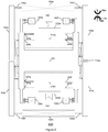
- FIG. 3 illustrates an embodiment of a single axis gyroscope comprising a guided mass system in accordance with the present invention.
- the guided mass system 600 is disposed in an X-Y plane.
- the guided mass system 600 includes guiding arms 104a, 104b, 104c and 104d that are flexibly coupled via springs 108a, 108b, 108c and 108d to the substrate 100 via the anchoring points 106a and 106b.
- Four guiding arms 104a, 104b, 104c and 104d are flexibly coupled to one traveling mass 105 via springs 103a, 103b, 103c and 103d.
- Each spring 103a-103d, 108a-108d is compliant in-plane about an axis in the Z-direction so that each guiding arm 104a-104b and 104 c-104d can rotate anti-phase in the plane while the traveling mass 105 translates in an X-direction.
- the yaw proof-masses 518a and 518b are flexibly connected to the traveling mass 105 via yaw-springs 520a-520d and 520e-520h, respectively.
- the guided mass system 600 can be driven at a drive frequency by a single drive circuit coupled to the actuators 109a-109d.
- the drive frequency can be a resonant frequency of the guided mass system 600.
- the guiding arms 104a-104b and 104c-104d rotate anti-phase in-plane and the traveling-mass 105 translates in-plane in the X-direction.
- Yaw-springs 520a-520d and 520e-520h are stiff in the X-direction such that when the guided mass system is driven, the yaw proof-masses 518a-b also translate with the traveling mass 105 in the X-direction.
- Angular velocity about a yaw-input axis in the Z-direction will cause a Coriolis force to act on the yaw proof-masses 518a-518b in the Y-direction resulting in a common mode motion of the yaw proof-masses 518a and 518b.
- the capacitive electrodes 522a and 522b are used to sense the motion of the yaw proof-masses 518a and 518b in the Y-direction which provides a measure of the angular velocity about the yaw-input axis.
- the configuration shown in Figure 3 can be represented as the spring mass configuration 11 of Figure 1 .
- guided mass system 600 eliminates the second harmonic motion by combining two guided mass systems by a rigid traveling mass 105. Since the motion of the lever arms 104a-104b and 104c-104d are anti-phase with respect to each other, the travelling mass 105 that is connected to the lever arms 104a-104d balances the opposing 2 nd harmonic motion and eliminates the unwanted non-linear component of the drive motion, and the y direction compliance of the spring elements 108a-108b, 103a-103b and 108c-108d, 103c-103d accommodates the 2 nd Harmonic motion by stretching in y direction similar to the spring mass configuration 12.
- guided mass system 500 can also be used as a dual axis gyroscope. If we assume that the springs 108a-108b and 108c-108d are compliant about a first and second roll-sense axis, respectively, where the first and second roll sense axes are parallel to each other and they are in the X-direction, then the guiding arms 104a-104b and 104c-104d can rotate anti-phase out-of-plane, whereby out-of-plane rotation of the guiding arms 104a-104d causes the traveling mass 105 to move out-of-plane with the guiding arms 104a-104d.
- Angular velocity about a roll-input axis in the Y-direction that is in the plane of the substrate and orthogonal to the X-direction will cause a Coriolis force to act on the traveling mass 105 in the Z-direction.
- the Coriolis force causes the lever arms 104a-104b and lever arms 104c-104d rotate anti-phase out-of-plane about the first and second roll-sense axes and the traveling mass 105 moves in the Z direction.
- the amplitude of the motion of the roll-travelling mass 105 is proportional to the angular velocity about the roll-input axis.
- a capacitive electrode 112a under the traveling mass 105 is used to detect the motion of the proof-mass. This motion provides a measure of the angular velocity about the roll-input axis.
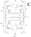
- Figure 4 illustrates a second embodiment of a single axis gyroscope comprising a guided mass system 700 in accordance with the present invention which minimizes a 2nd Harmonic component of the drive motion.
- the guided mass system 700 comprises two guided mass systems 700A and 700B, which are same as the guided mass system 500.
- the proof masses 102a and 102b, consequently two guided mass systems 700A and 700B, are connected by a coupling spring 151.
- the yaw proof-masses 518a and 518b are flexibly connected to the proof-masses 102a and 102b, respectively.
- the coupling spring 151 is torsionally compliant about an axis in the X-direction so that the symmetric guided mass systems 700A and 700B can rotate anti-phase out-of-plane about the first and second roll-sense axes.
- the coupling spring 151 is stiff in the Z-direction which prevents the guided mass systems 700A and 700B from rotating in-phase out-of-plane.
- the coupling spring 151 is stiff in the X-direction such that the proof-mass 102a and 102b move together in the X-direction. In this way the two guided mass systems 700A and 700B are driven together at a drive frequency by a single drive circuit coupled to the actuators 109a-109d.
- the configuration given in Figure 4 can be represented by the spring mass configuration 13 given in Figure 1 .
- two guided mass systems 700A and 700B are connected by a coupling spring 151, so that the proof masses 102a-102b and 518a-518b can also resonate in the Y direction at a certain natural frequency.
- Capacitive electrodes 522a and 522b are used to sense the motion of the proof-masses 518a and 518b in Y direction, respectively.
- the sensitive direction of the capacitive electrodes 522a-522b can be selected such a way that the 2 nd harmonic motion in the Y direction is rejected but the Coriolis motion in the Y direction is detected.
- the proof masses 518a and 518b move in the same direction in the drive motion.
- an angular velocity about a yaw-input axis in the Z-direction will impart a Coriolis force on the yaw proof-masses 518a-b in the same Y-direction (common mode motion).
- the capacitance of the electrodes 522a and 522b changes in opposite directions while the proof masses 518a-518b move in the same direction.
- the 2 nd harmonic motions of the proof masses 518a-518b in the Y direction are in opposite directions, because the guiding arms 104a-104b and 104c-104d are rotating around opposite directions. Consequently, the 2 nd harmonic motion of the proof masses 518a-518b will be cancelled due to the configuration of the electrodes 522a-522b.
- FIG. 5 illustrates another embodiment of a single axis gyroscope comprising a balanced guided mass system 1000 in accordance with an embodiment of the present invention.
- the guided mass system 1000 includes two symmetric guided mass systems 900a and 900b which are connected by a coupling spring 302.
- the coupling between the guided mass systems 900a and 900b doesn't have to be only a single coupling spring 302; the coupling may include various springs and spring-mass systems.
- the two symmetric guided mass systems 900a and 900b are arranged so that the proof-masses 102a-102d all move in the X-direction. Hence, the two guided mass systems 900a and 900b are driven together at a drive frequency by a single drive circuit coupled to the actuators 109a-109h.
- the proof-masses 102b and 102c move together in the same X-direction, since the coupling spring 302 is stiff in the X-direction.
- the proof masses 102a and 102d move in the opposite X-direction compared to the proof masses 102b and 102c.
- Angular velocity about the yaw-input axis will cause Coriolis forces to act on the yaw proof-masses 518a-518d resulting in motion of the yaw proof-masses 518a-518d along the Y-direction.
- the amplitude of the motions of the yaw proof-masses 518a-518d is proportional to the angular velocity about the yaw-input axis.
- the schematic provided in Figure 5 is a different embodiment of the spring-mass configuration 13 shown in Figure 1 .
- the balanced guided mass system 1000 eliminates the unwanted 2nd harmonic motion of the yaw proof masses 518a-518d by electrical cancellation.
- the imparted Coriolis forces on the proof masses 518a and 518d are in the opposite direction of the imparted Coriolis forces on the proof masses 518a and 518d.
- the Coriolis response motion of the proof masses 518b and 518c vs. the proof masses 518a and 518d are differential.
- the capacitance change of the electrodes 522a and 522b due to the Coriolis motion of the proof masses 518a-518b can be summed up.
- the capacitance change of the electrodes 522c and 522d can also be summed up.
- the detected capacitance change from the electrode pair 522c-522d can be subtracted from the detected capacitance change of the electrode pair 522a-522b.
- the Coriolis motion is detected.
- the 2nd harmonic motion direction of the each proof mass 518a-518d is illustrated by the arrows 541a-541d which are shown side by side by the arrows 540a-540d that are showing the Coriolis force direction of the proof masses 518a-518d.
- the given arrow configuration shows that the Coriolis force and the 2nd harmonic motion are in the same direction for the guided mass system 900b but they are in the opposite directions for the guided mass system 900a. As a result, the 2nd harmonic motion will be cancelled due to the electrode scheme given above.
- the balanced guided mass system 1000 can also be used as a dual axis gyroscope with a condition where the symmetric guided mass system 900a is able to rotate out-of-plane about a first roll-sense axis and the symmetric guided mass system 900b is able to rotate out-of-plane about a second roll-sense axis in-plane and parallel to the first roll-sense axis.
- the coupling spring 302 is connected to proof-masses 102b and 102c.
- the coupling spring 302 is torsionally compliant about an axis in the X-direction so that the symmetric guided mass systems 900a and 900b can rotate anti-phase out-of-plane about the first and second roll-sense axes.
- the coupling spring 302 is stiff in the Z-direction which prevents the symmetric guided mass systems 900a and 900b from rotating in-phase out-of-plane.
- Angular velocity about the roll-input axis will cause Coriolis forces to act on the proof-masses 102a-102d in the Z-direction.
- the Coriolis forces cause the symmetric guided mass systems 900a and 900b to rotate anti-phase out-of-plane about the first and second roll-sense axes.
- the amplitudes of the rotations of the symmetric guided mass systems 900a and 900b are proportional to the angular velocity.
- Capacitive electrodes 112a-112c under the proof masses 102a-102d are used to detect the rotations of the symmetric guided mass systems 900a and 900b.
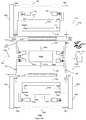
- Figure 6a illustrates an embodiment of a tri-axis gyroscope comprising a multiple guided mass system 1100 in accordance with the present invention.
- the multiple guided mass system 1100 includes two guided mass systems 500a and 500b coupled to a guided mass system 800 by coupling springs 302a and 302b, respectively.
- the guided mass systems 500a, 500b and 800 are arranged so that yaw proof-masses 518a and 518b coupled to roll proof masses 102a-102d all move anti-phase in the X-direction, the pitch proof-mass 650a rotates about an axis in the Z-direction.
- the guided mass system 500a rotates out-of-plane about a first roll-sense axis.
- the symmetric guided mass system 800 rotates out-of-plane about a second roll-sense axis parallel to the first roll-sense axis.
- the guided mass system 500b rotates out-of-plane about a third roll-sense axis parallel to the first and second roll-sense axes.
- the first coupling spring 302a is connected to proof-masses 102a and 102b.
- the coupling spring 302a is stiff in the X-direction such that proof-mass 102a and 102b move together in the X-direction.
- the second coupling spring 302b is connected to proof-masses 102c and 102d.
- the coupling spring 302b is stiff in the X-direction such that proof-mass 102c and 102d move together in the X-direction.
- the guided mass systems 500a, 500b, and 800 are driven together at a drive frequency by a single drive circuit coupled to the actuators 109a-109h.
- folded flexures are used as coupling springs 302a-b.
- the coupling spring 302a is torsionally compliant about an axis in the X-direction so that the guided mass systems 500a and 800 can rotate out-of-plane about the first and second roll-sense axes anti-phase.
- the coupling spring 302a prevents the symmetric guided mass systems 500a and 800 from rotating out-of-plane in-phase.
- the coupling spring 302b is also torsionally compliant about an axis in the X-direction so that the guided mass systems 500b and 800 can rotate out-of-plane about the second and third roll-sense axes anti-phase.
- the coupling spring 302b prevents the symmetric guided mass systems 500b and 800 from rotating out-of-plane in-phase.
- Angular velocity about the pitch-input axis will cause Coriolis forces to act on the pitch proof-mass 650a resulting in a torque that rotates the pitch proof-mass 650a about the pitch-sense axis.
- the amplitude of the rotation of the pitch proof-mass 650a is proportional to the angular velocity about the pitch-input axis.
- the capacitive electrodes 660a and 660b are disposed on opposite sides along the X-direction under the pitch proof-mass 650a and detect the rotation of the pitch proof-mass about the pitch-sense axis. The rotation provides a measure of the angular velocity about the pitch-input axis.
- Angular velocity about the roll-input axis will cause Coriolis forces to act on the proof-masses 102a and 102b in a Z-direction and on proof-masses 102c and 102d in the opposite Z-direction.
- the Coriolis forces cause the guided mass systems 500a, 800, and 500b to rotate out-of-plane about the first, second, and third roll-sense axis respectively.
- the capacitive electrode 112b under the proof masses 102a and 102b and the capacitive electrode 112a under the proof masses 102c and 102d are used to detect the rotation of the guided mass system 1100. This rotation provides a measure of the angular velocity about the roll-input axis.
- Angular velocity about the yaw-input axis will cause Coriolis forces to act on the yaw proof-masses 518a and 518b resulting in motion of the yaw proof-masses 518a and 518b anti-phase along the Y-direction.
- the amplitude of the motion of the yaw proof-masses along the Y-direction is proportional to the angular velocity.
- the capacitive electrodes 522a and 522b are used to sense the motion of the respective yaw proof masses 518a and 518b along the Y-direction.
- the multiple guided mass system 1100 of Figure 6a can be represented by the spring mass configuration 12 shown in Figure 1 .
- the spring-mass system 12A is a representation of one of the guided mass systems 500a or 500b
- the spring-mass system 12B is a representation of the guided mass system 800.
- the springs 103c-103f and 108c-108d are compliant in y direction and their compliance can be modeled by an equivalent spring as 42B, which is given in spring mass system configuration 12 in Figure 1 .
- the springs 108a-108b, 103g-103h and 520a-520d can be modeled by the spring 42A.
- the coupling spring 302a that connects 500a and 800 can be modeled as spring 22.
- the lever arms 104c-104d can be modeled as the lever arm 22B, and the lever arms 104a-104b can be represented as 22A.
- Y direction spring stiffness of the guided mass system 800 is much higher than the y direction spring stiffness of the guided mass system 500a or 500b. The reason is that the springs sets 103c-103d and 103e-103f have been equally spread in the guided mass system 800, and also the springs 652a and 652b are very stiff in Y direction.
- the y direction spring stiffness of the springs 103c-103f, 108c-108d, and 652a-652b can be made equal to the sum of the spring stiffness of the coupling spring 302a and the springs 108a-108b, 103g-103h and 520a-520d.
- the net nonlinear motion in y direction of the yaw-proof masses 518a-518b can be eliminated by the help of the balance of the opposing forces in y direction.
- a folded flexure is used as coupling spring 302a.
- the main benefit of using a folded flexure is to increase the y direction translational stiffness of coupling spring 302a, while maintaining its out-of plane torsional compliance within the given area.
- a two-fold folded flexure is used in embodiment 1100, folded flexure with many folds can also be used to increase the y direction translational stiffness.
- Figure 6b illustrates another embodiment of a tri-axis gyroscope comprising a multiple guided mass system 1110 in accordance with the present invention.
- Multiple guided mass system is same as multiple guided mass system 1100, except new coupling springs 303a and 303b are added in between proof masses 102a-b and 102c-d respectively.
- Main benefit of adding springs 303a and 303b in multiple guided system 1110 is to increase the y direction translational stiffness.
- springs 303a-b improves x direction stiffness.
- rigidity of multiple guided mass system 1110 during the drive motion increases and proof masses 102a-b and 102c-d move together in the x direction.
- Embodiments for modifying a spring mass configuration are disclosed that minimize the effects of unwanted nonlinear motion on a MEMS sensor.
- the modifications include any or any combination of providing a rigid element between rotating structures of the spring mass configuration, tuning a spring system between the rotating structures and coupling an electrical cancellation system to the rotating structures. In so doing unwanted nonlinear motion such as unwanted 2 nd harmonic motion is minimized.
Landscapes
- Engineering & Computer Science (AREA)
- Physics & Mathematics (AREA)
- General Physics & Mathematics (AREA)
- Radar, Positioning & Navigation (AREA)
- Remote Sensing (AREA)
- Computer Hardware Design (AREA)
- Microelectronics & Electronic Packaging (AREA)
- Gyroscopes (AREA)
Claims (13)
- Ein MEMS-Winkelgeschwindigkeitssensor, umfassend:einen ersten (22A) und zweiten (22B) rotierenden Arm, wobei der erste und zweite rotierende Arm miteinander gekoppelt sind und der erste und zweite rotierende Arm so eingerichtet sind, dass sie sich gegenläufig drehen, wenn sie in Schwingung versetzt werden;mindestens ein bewegliches System (101 B), umfassend eine erste bewegliche Masse (32A) und eine zweite bewegliche Masse (32B);wobei die erste bewegliche Masse durch ein erstes flexibles Element (42A) mit dem ersten rotierenden Arm gekoppelt ist und die zweite bewegliche Masse durch ein zweites flexibles Element (42B) mit dem zweiten rotierenden Arm gekoppelt ist;wobei die erste und die zweite bewegliche Masse mit einem dritten flexiblen Element (22) miteinander gekoppelt sind; undmindestens einen Aktuator um das mindestens eine bewegliche System in Schwingung zu versetzen;dadurch gekennzeichnet, dassdas erste flexible Element einen anderen Federsteifigkeitswert als das zweite flexible Element aufweist,wobei eine Federsteifigkeit des zweiten flexiblen Elements gleich einer kombinierten Federsteifigkeit des ersten flexiblen Elements und des dritten flexiblen Elements ist; undwobei die erste bewegliche Masse so eingerichtet ist, dass sie sich linear nur in einer ersten Richtung X einer X-Y-Ebene bewegt, wenn sie in Schwingung versetzt wird, und die zweite bewegliche Masse so eingerichtet ist, dass sie sich in der ersten Richtung X und in einer zweiten Richtung Y der X-Y-Ebene bewegt, die orthogonal zur ersten Richtung X ist, wenn sie in Schwingung versetzt wird, als Ergebnis davon, dass das erste flexible Element den anderen Federsteifigkeitswert als das zweite flexible Element aufweist.
- MEMS-Sensor nach Anspruch 1, wobei sich das mindestens eine bewegliche System (101B) in einer Ebene parallel zu einem Substrat des Sensors bewegt.
- MEMS-Sensor nach Anspruch 2, wobei der erste und der zweite rotierende Arm (22A, 22B) durch einen Satz flexibler Elemente (52A, 52B) mit einem Anker (62A, 62B) auf dem Substrat verbunden sind.
- MEMS-Sensor nach Anspruch 1, ferner umfassend:
mindestens einen Wandler, der eingerichtet ist, Bewegung eines Teils des mindestens einen beweglichen Systems (101B) zu erfassen. - MEMS-Sensor nach Anspruch 4, wobei der mindestens eine Wandler mindestens einen kapazitiven Wandler, einen optischen Wandler oder einen piezoelektrischen Wandler umfasst.
- MEMS-Sensor nach Anspruch 4, wobei der mindestens eine Wandler Bewegung eines Teils des mindestens einen beweglichen Systems (101B) in der zweiten Richtung erfasst.
- MEMS-Sensor nach Anspruch 1, wobei die ersten (42A) und zweiten (42B) flexiblen Elemente, die mit dem ersten (22A) und zweiten (22B) rotierenden Arm gekoppelt sind, eingerichtet sind, eine Drehung des ersten und zweiten rotierenden Arms innerhalb der X-Y-Ebene zu erlauben.
- MEMS-Sensor nach Anspruch 6, wobei die erste bewegliche Masse mindestens eine erste Prüfmasse (102a) und mindestens eine zweite Prüfmasse (518a) umfasst, die miteinander gekoppelt sind, wobei die zweite Prüfmasse (518a) eingerichtet ist weniger als jeweiligen Teile des ersten und zweiten rotierenden Arms in der ersten Richtung verschoben zu werden, wenn sich der erste und zweite rotierende Arm gegenläufig drehen, wenn sie in Schwingung versetzt wurden.
- MEMS-Sensor nach Anspruch 1, wobei der erste und der zweite rotierende Arm in Bezug auf das mindestens eine bewegliche System symmetrisch angeordnet sind.
- MEMS-Sensor nach Anspruch 8, wobei die zweite Prüfmasse (518a) flexibel mit der ersten Prüfmasse (102a) gekoppelt ist und sich relativ zur ersten Prüfmasse in der zweiten Richtung bewegen kann.
- MEMS-Sensor nach Anspruch 1, wobei ein erster Wandler (112b) Bewegung eines Teils der ersten beweglichen Masse (32A) und eines Teils der zweiten beweglichen Masse (32B) in einer dritten Richtung orthogonal zur ersten und zweiten Richtung erfasst.
- MEMS-Sensor nach Anspruch 11, wobei ein zweiter Wandler (522a) die Bewegung eines Teils der ersten beweglichen Masse (32A) in der zweiten Richtung erfasst.
- MEMS-Sensor nach Anspruch 8, wobei der mindestens eine Wandler (522a) zum Erfassen einer Bewegung von mindestens einem Teil der zweiten Prüfmasse (518a) als Reaktion auf einen Eingang der Winkelgeschwindigkeit ist.
Priority Applications (1)
| Application Number | Priority Date | Filing Date | Title |
|---|---|---|---|
| EP20209488.4A EP3812705A1 (de) | 2014-01-21 | 2015-01-21 | Mems-sensor mit konfiguration zur reduzierung nichtlinearer bewegung |
Applications Claiming Priority (2)
| Application Number | Priority Date | Filing Date | Title |
|---|---|---|---|
| US201461929838P | 2014-01-21 | 2014-01-21 | |
| US14/495,786 US9958271B2 (en) | 2014-01-21 | 2014-09-24 | Configuration to reduce non-linear motion |
Related Child Applications (1)
| Application Number | Title | Priority Date | Filing Date |
|---|---|---|---|
| EP20209488.4A Division EP3812705A1 (de) | 2014-01-21 | 2015-01-21 | Mems-sensor mit konfiguration zur reduzierung nichtlinearer bewegung |
Publications (2)
| Publication Number | Publication Date |
|---|---|
| EP2899503A1 EP2899503A1 (de) | 2015-07-29 |
| EP2899503B1 true EP2899503B1 (de) | 2020-11-25 |
Family
ID=52465183
Family Applications (2)
| Application Number | Title | Priority Date | Filing Date |
|---|---|---|---|
| EP15152031.9A Active EP2899503B1 (de) | 2014-01-21 | 2015-01-21 | MEMS-Sensor mit Anordnung zur Reduzierung von nichtlinearer Bewegung |
| EP20209488.4A Pending EP3812705A1 (de) | 2014-01-21 | 2015-01-21 | Mems-sensor mit konfiguration zur reduzierung nichtlinearer bewegung |
Family Applications After (1)
| Application Number | Title | Priority Date | Filing Date |
|---|---|---|---|
| EP20209488.4A Pending EP3812705A1 (de) | 2014-01-21 | 2015-01-21 | Mems-sensor mit konfiguration zur reduzierung nichtlinearer bewegung |
Country Status (4)
| Country | Link |
|---|---|
| US (3) | US9958271B2 (de) |
| EP (2) | EP2899503B1 (de) |
| KR (1) | KR101835932B1 (de) |
| CN (2) | CN104964678B (de) |
Families Citing this family (27)
| Publication number | Priority date | Publication date | Assignee | Title |
|---|---|---|---|---|
| US10914584B2 (en) | 2011-09-16 | 2021-02-09 | Invensense, Inc. | Drive and sense balanced, semi-coupled 3-axis gyroscope |
| US9958271B2 (en) * | 2014-01-21 | 2018-05-01 | Invensense, Inc. | Configuration to reduce non-linear motion |
| TWI632345B (zh) * | 2016-05-27 | 2018-08-11 | 日商村田製作所股份有限公司 | 振動的微機電陀螺儀之驅動振輻的持續性監控與相關方法 |
| US10126129B2 (en) * | 2016-07-11 | 2018-11-13 | Nxp Usa, Inc. | Vibration and shock robust gyroscope |
| US10466053B2 (en) | 2017-04-04 | 2019-11-05 | Invensense, Inc. | Out-of-plane sensing gyroscope robust to external acceleration and rotation |
| JP6610706B2 (ja) | 2017-05-24 | 2019-11-27 | 株式会社村田製作所 | 横駆動変換器を備える圧電ジャイロスコープ |
| JP6627912B2 (ja) | 2017-05-24 | 2020-01-08 | 株式会社村田製作所 | 圧電回転mems共振器 |
| JP6696530B2 (ja) | 2017-05-24 | 2020-05-20 | 株式会社村田製作所 | 圧電ジャイロスコープにおける連結懸架 |
| JP6627911B2 (ja) | 2017-05-24 | 2020-01-08 | 株式会社村田製作所 | 圧電回転mems共振器 |
| WO2019010246A1 (en) * | 2017-07-06 | 2019-01-10 | Invensense, Inc. | BALANCED, THREE-AXIS, SEMI-COUPLED, DRIVING AND DETECTION GYROSCOPE |
| JP7112876B2 (ja) | 2017-07-06 | 2022-08-04 | 浜松ホトニクス株式会社 | 光学デバイス |
| JP6503150B1 (ja) | 2017-07-06 | 2019-04-17 | 浜松ホトニクス株式会社 | 光学デバイス |
| CN114384686B (zh) | 2017-07-06 | 2024-05-14 | 浜松光子学株式会社 | 光学装置 |
| JP6514804B1 (ja) | 2017-07-06 | 2019-05-15 | 浜松ホトニクス株式会社 | 光学デバイス |
| US12180063B2 (en) | 2017-07-06 | 2024-12-31 | Hamamatsu Photonics K.K. | Optical device and method for manufacturing same |
| CN110799882A (zh) | 2017-07-06 | 2020-02-14 | 浜松光子学株式会社 | 光学器件 |
| JP6503151B1 (ja) | 2017-07-06 | 2019-04-17 | 浜松ホトニクス株式会社 | 光学デバイス |
| CN115657296A (zh) | 2017-11-15 | 2023-01-31 | 浜松光子学株式会社 | 光学器件的制造方法 |
| CN109935223B (zh) * | 2017-12-19 | 2021-04-20 | 北京长城电子装备有限责任公司 | 一种超小尺寸低频发射换能器 |
| EP3598146B1 (de) * | 2018-07-16 | 2022-05-11 | Murata Manufacturing Co., Ltd. | Mikroelektromechanische vorrichtung zur erkennung von bewegung ausserhalb der ebene |
| JP7188311B2 (ja) | 2019-07-31 | 2022-12-13 | セイコーエプソン株式会社 | ジャイロセンサー、電子機器、及び移動体 |
| US11193771B1 (en) | 2020-06-05 | 2021-12-07 | Analog Devices, Inc. | 3-axis gyroscope with rotational vibration rejection |
| US11619492B2 (en) | 2021-06-10 | 2023-04-04 | Invensense, Inc. | Sensor linearization based upon correction of static and frequency-dependent non-linearities |
| IT202100020504A1 (it) * | 2021-07-30 | 2023-01-30 | St Microelectronics Srl | Giroscopio mems avente una migliorata reiezione all'errore di quadratura |
| CN114487480B (zh) * | 2022-01-14 | 2025-09-16 | 瑞声开泰科技(武汉)有限公司 | 微机电系统加速度计 |
| DE102023204632A1 (de) * | 2022-05-17 | 2023-11-23 | Murata Manufacturing Co., Ltd. | MEMS-Gyroskop, das Drehungen in einer Ebene erfasst |
| US20240003685A1 (en) * | 2022-07-01 | 2024-01-04 | Stmicroelectronics S.R.L. | Mems gyroscope with enhanced robustness against vibrations and reduced dimensions |
Citations (1)
| Publication number | Priority date | Publication date | Assignee | Title |
|---|---|---|---|---|
| US20130068018A1 (en) * | 2011-09-16 | 2013-03-21 | Invensense, Inc. | Micromachined gyroscope including a guided mass system |
Family Cites Families (65)
| Publication number | Priority date | Publication date | Assignee | Title |
|---|---|---|---|---|
| US4510802A (en) | 1983-09-02 | 1985-04-16 | Sundstrand Data Control, Inc. | Angular rate sensor utilizing two vibrating accelerometers secured to a parallelogram linkage |
| US5349855A (en) | 1992-04-07 | 1994-09-27 | The Charles Stark Draper Laboratory, Inc. | Comb drive micromechanical tuning fork gyro |
| US5481914A (en) | 1994-03-28 | 1996-01-09 | The Charles Stark Draper Laboratory, Inc. | Electronics for coriolis force and other sensors |
| DE4414237A1 (de) | 1994-04-23 | 1995-10-26 | Bosch Gmbh Robert | Mikromechanischer Schwinger eines Schwingungsgyrometers |
| US5992233A (en) | 1996-05-31 | 1999-11-30 | The Regents Of The University Of California | Micromachined Z-axis vibratory rate gyroscope |
| US6250156B1 (en) * | 1996-05-31 | 2001-06-26 | The Regents Of The University Of California | Dual-mass micromachined vibratory rate gyroscope |
| US6230563B1 (en) | 1998-06-09 | 2001-05-15 | Integrated Micro Instruments, Inc. | Dual-mass vibratory rate gyroscope with suppressed translational acceleration response and quadrature-error correction capability |
| DE19938206A1 (de) | 1999-08-12 | 2001-02-15 | Bosch Gmbh Robert | Mikromechanischer Drehbeschleunigungssensor |
| US6508122B1 (en) | 1999-09-16 | 2003-01-21 | American Gnc Corporation | Microelectromechanical system for measuring angular rate |
| US6845669B2 (en) | 2001-05-02 | 2005-01-25 | The Regents Of The University Of California | Non-resonant four degrees-of-freedom micromachined gyroscope |
| WO2003031912A2 (en) | 2001-10-05 | 2003-04-17 | The Charles Stark Draper Laboratory, Inc. | Tuning fork gyroscope |
| US6715353B2 (en) | 2002-04-25 | 2004-04-06 | Honeywell International, Inc. | MEMS gyroscope with parametric gain |
| US6701786B2 (en) * | 2002-04-29 | 2004-03-09 | L-3 Communications Corporation | Closed loop analog gyro rate sensor |
| US6848304B2 (en) | 2003-04-28 | 2005-02-01 | Analog Devices, Inc. | Six degree-of-freedom micro-machined multi-sensor |
| US7036372B2 (en) | 2003-09-25 | 2006-05-02 | Kionix, Inc. | Z-axis angular rate sensor |
| US20050066728A1 (en) | 2003-09-25 | 2005-03-31 | Kionix, Inc. | Z-axis angular rate micro electro-mechanical systems (MEMS) sensor |
| US6892575B2 (en) | 2003-10-20 | 2005-05-17 | Invensense Inc. | X-Y axis dual-mass tuning fork gyroscope with vertically integrated electronics and wafer-scale hermetic packaging |
| US7458263B2 (en) | 2003-10-20 | 2008-12-02 | Invensense Inc. | Method of making an X-Y axis dual-mass tuning fork gyroscope with vertically integrated electronics and wafer-scale hermetic packaging |
| US6939473B2 (en) | 2003-10-20 | 2005-09-06 | Invensense Inc. | Method of making an X-Y axis dual-mass tuning fork gyroscope with vertically integrated electronics and wafer-scale hermetic packaging |
| DE10350037A1 (de) * | 2003-10-27 | 2005-05-25 | Robert Bosch Gmbh | Drehratensensor |
| US7377167B2 (en) | 2004-02-27 | 2008-05-27 | The Regents Of The University Of California | Nonresonant micromachined gyroscopes with structural mode-decoupling |
| EP1617178B1 (de) | 2004-07-12 | 2017-04-12 | STMicroelectronics Srl | Mikroelektromechanische Struktur mit elektrisch isolierten Gebieten und Verfahren zu ihrer Herstellung |
| JP4353087B2 (ja) | 2004-12-01 | 2009-10-28 | 株式会社デンソー | 回転振動型角速度センサ |
| US7284430B2 (en) | 2005-08-15 | 2007-10-23 | The Regents Of The University Of California | Robust micromachined gyroscopes with two degrees of freedom sense-mode oscillator |
| US7621183B2 (en) | 2005-11-18 | 2009-11-24 | Invensense Inc. | X-Y axis dual-mass tuning fork gyroscope with vertically integrated electronics and wafer-scale hermetic packaging |
| EP1832841B1 (de) | 2006-03-10 | 2015-12-30 | STMicroelectronics Srl | Mikroelektromechanische integrierte Sensorstruktur mit Rotationsantriebsbewegung |
| US7526957B2 (en) | 2006-04-18 | 2009-05-05 | Watson Industries, Inc. | Vibrating inertial rate sensor utilizing skewed drive or sense elements |
| US7444868B2 (en) | 2006-06-29 | 2008-11-04 | Honeywell International Inc. | Force rebalancing for MEMS inertial sensors using time-varying voltages |
| US8141424B2 (en) | 2008-09-12 | 2012-03-27 | Invensense, Inc. | Low inertia frame for detecting coriolis acceleration |
| US20100071467A1 (en) | 2008-09-24 | 2010-03-25 | Invensense | Integrated multiaxis motion sensor |
| US8020441B2 (en) | 2008-02-05 | 2011-09-20 | Invensense, Inc. | Dual mode sensing for vibratory gyroscope |
| US20080238537A1 (en) * | 2007-04-02 | 2008-10-02 | Honeywell International Inc. | Methods and systems for driver noise reduction in a mems gyro |
| DE102007030120B4 (de) * | 2007-06-29 | 2010-04-08 | Litef Gmbh | Drehratensensor |
| KR100885416B1 (ko) | 2007-07-19 | 2009-02-24 | 건국대학교 산학협력단 | 일체형 가속도계·각속도계 구동 시스템 |
| DE102007035806B4 (de) | 2007-07-31 | 2011-03-17 | Sensordynamics Ag | Mikromechanischer Drehratensensor |
| US8042394B2 (en) | 2007-09-11 | 2011-10-25 | Stmicroelectronics S.R.L. | High sensitivity microelectromechanical sensor with rotary driving motion |
| US7677099B2 (en) * | 2007-11-05 | 2010-03-16 | Invensense Inc. | Integrated microelectromechanical systems (MEMS) vibrating mass Z-axis rate sensor |
| CN101939653B (zh) * | 2008-02-05 | 2014-12-03 | 因文森斯公司 | 具有垂直集成的电子器件和晶片级密封式封装的x-y轴双质量块音叉陀螺仪 |
| FI122397B (fi) | 2008-04-16 | 2011-12-30 | Vti Technologies Oy | Värähtelevä mikromekaaninen kulmanopeusanturi |
| RU2388999C1 (ru) * | 2008-09-01 | 2010-05-10 | Открытое акционерное общество "Концерн "Центральный научно-исследовательский институт "Электроприбор" | Микромеханический гироскоп (варианты) и способы его настройки, основанные на использовании амплитудно-модулированного квадратурного тестового воздействия |
| CN102301214A (zh) * | 2009-01-27 | 2011-12-28 | 通用电气公司 | Mems装置和利用该mems装置的远程传感系统 |
| US8210038B2 (en) * | 2009-02-17 | 2012-07-03 | Robert Bosch Gmbh | Drive frequency tunable MEMS gyroscope |
| FI20095201A0 (fi) | 2009-03-02 | 2009-03-02 | Vti Technologies Oy | Värähtelevä mikromekaaninen kulmanopeusanturi |
| US8646308B2 (en) | 2009-04-03 | 2014-02-11 | Analog Devices, Inc. | Robust self testing of a motion sensor system |
| US8322213B2 (en) * | 2009-06-12 | 2012-12-04 | The Regents Of The University Of California | Micromachined tuning fork gyroscopes with ultra-high sensitivity and shock rejection |
| ITTO20090597A1 (it) | 2009-07-31 | 2011-02-01 | St Microelectronics Srl | Struttura di rilevamento microelettromeccanica ad asse z con ridotte derive termiche |
| DE102010040514A1 (de) * | 2009-09-09 | 2011-04-21 | Continental Teves Ag & Co. Ohg | Doppelaxialer, schockrobuster Drehratensensor mit linearen und rotatorischen seismischen Elementen |
| US8534127B2 (en) * | 2009-09-11 | 2013-09-17 | Invensense, Inc. | Extension-mode angular velocity sensor |
| US9097524B2 (en) * | 2009-09-11 | 2015-08-04 | Invensense, Inc. | MEMS device with improved spring system |
| ITTO20091042A1 (it) | 2009-12-24 | 2011-06-25 | St Microelectronics Srl | Giroscopio integrato microelettromeccanico con migliorata struttura di azionamento |
| EP2378246A1 (de) * | 2010-04-16 | 2011-10-19 | SensoNor Technologies AS | MEMS-Struktur für einen Winkelgeschwindigkeitssensor |
| FI124020B (fi) | 2011-03-04 | 2014-02-14 | Murata Electronics Oy | Jousirakenne, resonaattori, resonaattorimatriisi ja anturi |
| US8726717B2 (en) | 2011-04-27 | 2014-05-20 | Honeywell International Inc. | Adjusting a MEMS gyroscope to reduce thermally varying bias |
| JP5822177B2 (ja) | 2011-05-20 | 2015-11-24 | セイコーエプソン株式会社 | ジャイロセンサー、電子機器 |
| EP2570770B1 (de) | 2011-09-13 | 2021-06-23 | IMEC vzw | Dreimassige gekoppelte oszillationstechnik für mechanisch robuste mikroverarbeitete gyroskope |
| US9170107B2 (en) * | 2011-09-16 | 2015-10-27 | Invensense, Inc. | Micromachined gyroscope including a guided mass system |
| US9714842B2 (en) | 2011-09-16 | 2017-07-25 | Invensense, Inc. | Gyroscope self test by applying rotation on coriolis sense mass |
| US8448513B2 (en) | 2011-10-05 | 2013-05-28 | Freescale Semiconductor, Inc. | Rotary disk gyroscope |
| US8739627B2 (en) | 2011-10-26 | 2014-06-03 | Freescale Semiconductor, Inc. | Inertial sensor with off-axis spring system |
| KR101371149B1 (ko) | 2012-01-18 | 2014-03-06 | 주식회사 에스알파워 | 멤즈 기반의 자이로스코프 |
| US9759563B2 (en) * | 2012-01-31 | 2017-09-12 | Nxp Usa, Inc. | Vibration robust x-axis ring gyro transducer |
| CN103245340B (zh) | 2012-02-01 | 2016-07-13 | 苏州敏芯微电子技术股份有限公司 | 一种单芯片三轴陀螺仪 |
| US8680926B2 (en) * | 2012-05-01 | 2014-03-25 | Invensense, Inc. | Amplification circuit comprising input signal limiting network |
| CN103234536B (zh) * | 2013-04-15 | 2017-02-08 | 北方工业大学 | 一种压电驱动三自由度扭转振动mems陀螺的设计方法 |
| US9958271B2 (en) | 2014-01-21 | 2018-05-01 | Invensense, Inc. | Configuration to reduce non-linear motion |
-
2014
- 2014-09-24 US US14/495,786 patent/US9958271B2/en active Active
-
2015
- 2015-01-21 EP EP15152031.9A patent/EP2899503B1/de active Active
- 2015-01-21 CN CN201510030426.6A patent/CN104964678B/zh active Active
- 2015-01-21 KR KR1020150009691A patent/KR101835932B1/ko active Active
- 2015-01-21 CN CN201811189802.6A patent/CN109520489B/zh active Active
- 2015-01-21 EP EP20209488.4A patent/EP3812705A1/de active Pending
-
2017
- 2017-11-15 US US15/814,373 patent/US10527421B2/en active Active
-
2020
- 2020-01-06 US US16/735,351 patent/US11047685B2/en active Active
Patent Citations (1)
| Publication number | Priority date | Publication date | Assignee | Title |
|---|---|---|---|---|
| US20130068018A1 (en) * | 2011-09-16 | 2013-03-21 | Invensense, Inc. | Micromachined gyroscope including a guided mass system |
Also Published As
| Publication number | Publication date |
|---|---|
| US9958271B2 (en) | 2018-05-01 |
| US11047685B2 (en) | 2021-06-29 |
| CN104964678B (zh) | 2018-11-06 |
| US20180073875A1 (en) | 2018-03-15 |
| US10527421B2 (en) | 2020-01-07 |
| US20160363445A1 (en) | 2016-12-15 |
| US20200225038A1 (en) | 2020-07-16 |
| EP2899503A1 (de) | 2015-07-29 |
| CN109520489B (zh) | 2022-10-18 |
| EP3812705A1 (de) | 2021-04-28 |
| KR20150087136A (ko) | 2015-07-29 |
| CN109520489A (zh) | 2019-03-26 |
| CN104964678A (zh) | 2015-10-07 |
| KR101835932B1 (ko) | 2018-03-08 |
Similar Documents
| Publication | Publication Date | Title |
|---|---|---|
| EP2899503B1 (de) | MEMS-Sensor mit Anordnung zur Reduzierung von nichtlinearer Bewegung | |
| US12228404B2 (en) | Drive and sense balanced, semi-coupled 3-axis gyroscope | |
| EP2748559B1 (de) | Mikrogefertigtes gyroskop mit einem geführten massesystem | |
| CN103630127B (zh) | 转速传感器 | |
| US9170107B2 (en) | Micromachined gyroscope including a guided mass system | |
| US20130180332A1 (en) | Fully Decoupled Lateral Axis Gyroscope with Thickness-Insensitive Z-Axis Spring and Symmetric Teeter Totter Sensing Element | |
| US9863769B2 (en) | MEMS sensor with decoupled drive system | |
| EP3184961B1 (de) | Mikrogefertigtes gyroskop mit einem geführten massesystem | |
| EP2955480B1 (de) | Mems-sensor mit entkoppeltem antriebssystem | |
| EP3649432B1 (de) | Antriebs- und erfassungsausgeglichenes, halbgekoppeltes dreiachsiges gyroskop | |
| US9581445B2 (en) | Torsional rate measuring gyroscope |
Legal Events
| Date | Code | Title | Description |
|---|---|---|---|
| PUAI | Public reference made under article 153(3) epc to a published international application that has entered the european phase |
Free format text: ORIGINAL CODE: 0009012 |
|
| 17P | Request for examination filed |
Effective date: 20150121 |
|
| AK | Designated contracting states |
Kind code of ref document: A1 Designated state(s): AL AT BE BG CH CY CZ DE DK EE ES FI FR GB GR HR HU IE IS IT LI LT LU LV MC MK MT NL NO PL PT RO RS SE SI SK SM TR |
|
| AX | Request for extension of the european patent |
Extension state: BA ME |
|
| RBV | Designated contracting states (corrected) |
Designated state(s): AL AT BE BG CH CY CZ DE DK EE ES FI FR GB GR HR HU IE IS IT LI LT LU LV MC MK MT NL NO PL PT RO RS SE SI SK SM TR |
|
| STAA | Information on the status of an ep patent application or granted ep patent |
Free format text: STATUS: EXAMINATION IS IN PROGRESS |
|
| 17Q | First examination report despatched |
Effective date: 20190531 |
|
| GRAP | Despatch of communication of intention to grant a patent |
Free format text: ORIGINAL CODE: EPIDOSNIGR1 |
|
| STAA | Information on the status of an ep patent application or granted ep patent |
Free format text: STATUS: GRANT OF PATENT IS INTENDED |
|
| INTG | Intention to grant announced |
Effective date: 20200616 |
|
| GRAS | Grant fee paid |
Free format text: ORIGINAL CODE: EPIDOSNIGR3 |
|
| GRAA | (expected) grant |
Free format text: ORIGINAL CODE: 0009210 |
|
| STAA | Information on the status of an ep patent application or granted ep patent |
Free format text: STATUS: THE PATENT HAS BEEN GRANTED |
|
| AK | Designated contracting states |
Kind code of ref document: B1 Designated state(s): AL AT BE BG CH CY CZ DE DK EE ES FI FR GB GR HR HU IE IS IT LI LT LU LV MC MK MT NL NO PL PT RO RS SE SI SK SM TR |
|
| REG | Reference to a national code |
Ref country code: GB Ref legal event code: FG4D |
|
| REG | Reference to a national code |
Ref country code: CH Ref legal event code: EP |
|
| REG | Reference to a national code |
Ref country code: DE Ref legal event code: R096 Ref document number: 602015062411 Country of ref document: DE |
|
| REG | Reference to a national code |
Ref country code: AT Ref legal event code: REF Ref document number: 1338837 Country of ref document: AT Kind code of ref document: T Effective date: 20201215 |
|
| REG | Reference to a national code |
Ref country code: IE Ref legal event code: FG4D |
|
| REG | Reference to a national code |
Ref country code: AT Ref legal event code: MK05 Ref document number: 1338837 Country of ref document: AT Kind code of ref document: T Effective date: 20201125 |
|
| REG | Reference to a national code |
Ref country code: NL Ref legal event code: MP Effective date: 20201125 |
|
| PG25 | Lapsed in a contracting state [announced via postgrant information from national office to epo] |
Ref country code: PT Free format text: LAPSE BECAUSE OF FAILURE TO SUBMIT A TRANSLATION OF THE DESCRIPTION OR TO PAY THE FEE WITHIN THE PRESCRIBED TIME-LIMIT Effective date: 20210325 Ref country code: NO Free format text: LAPSE BECAUSE OF FAILURE TO SUBMIT A TRANSLATION OF THE DESCRIPTION OR TO PAY THE FEE WITHIN THE PRESCRIBED TIME-LIMIT Effective date: 20210225 Ref country code: FI Free format text: LAPSE BECAUSE OF FAILURE TO SUBMIT A TRANSLATION OF THE DESCRIPTION OR TO PAY THE FEE WITHIN THE PRESCRIBED TIME-LIMIT Effective date: 20201125 Ref country code: RS Free format text: LAPSE BECAUSE OF FAILURE TO SUBMIT A TRANSLATION OF THE DESCRIPTION OR TO PAY THE FEE WITHIN THE PRESCRIBED TIME-LIMIT Effective date: 20201125 Ref country code: GR Free format text: LAPSE BECAUSE OF FAILURE TO SUBMIT A TRANSLATION OF THE DESCRIPTION OR TO PAY THE FEE WITHIN THE PRESCRIBED TIME-LIMIT Effective date: 20210226 |
|
| PG25 | Lapsed in a contracting state [announced via postgrant information from national office to epo] |
Ref country code: LV Free format text: LAPSE BECAUSE OF FAILURE TO SUBMIT A TRANSLATION OF THE DESCRIPTION OR TO PAY THE FEE WITHIN THE PRESCRIBED TIME-LIMIT Effective date: 20201125 Ref country code: SE Free format text: LAPSE BECAUSE OF FAILURE TO SUBMIT A TRANSLATION OF THE DESCRIPTION OR TO PAY THE FEE WITHIN THE PRESCRIBED TIME-LIMIT Effective date: 20201125 Ref country code: IS Free format text: LAPSE BECAUSE OF FAILURE TO SUBMIT A TRANSLATION OF THE DESCRIPTION OR TO PAY THE FEE WITHIN THE PRESCRIBED TIME-LIMIT Effective date: 20210325 Ref country code: PL Free format text: LAPSE BECAUSE OF FAILURE TO SUBMIT A TRANSLATION OF THE DESCRIPTION OR TO PAY THE FEE WITHIN THE PRESCRIBED TIME-LIMIT Effective date: 20201125 Ref country code: AT Free format text: LAPSE BECAUSE OF FAILURE TO SUBMIT A TRANSLATION OF THE DESCRIPTION OR TO PAY THE FEE WITHIN THE PRESCRIBED TIME-LIMIT Effective date: 20201125 Ref country code: BG Free format text: LAPSE BECAUSE OF FAILURE TO SUBMIT A TRANSLATION OF THE DESCRIPTION OR TO PAY THE FEE WITHIN THE PRESCRIBED TIME-LIMIT Effective date: 20210225 |
|
| REG | Reference to a national code |
Ref country code: LT Ref legal event code: MG9D |
|
| PG25 | Lapsed in a contracting state [announced via postgrant information from national office to epo] |
Ref country code: HR Free format text: LAPSE BECAUSE OF FAILURE TO SUBMIT A TRANSLATION OF THE DESCRIPTION OR TO PAY THE FEE WITHIN THE PRESCRIBED TIME-LIMIT Effective date: 20201125 |
|
| PG25 | Lapsed in a contracting state [announced via postgrant information from national office to epo] |
Ref country code: SM Free format text: LAPSE BECAUSE OF FAILURE TO SUBMIT A TRANSLATION OF THE DESCRIPTION OR TO PAY THE FEE WITHIN THE PRESCRIBED TIME-LIMIT Effective date: 20201125 Ref country code: CZ Free format text: LAPSE BECAUSE OF FAILURE TO SUBMIT A TRANSLATION OF THE DESCRIPTION OR TO PAY THE FEE WITHIN THE PRESCRIBED TIME-LIMIT Effective date: 20201125 Ref country code: EE Free format text: LAPSE BECAUSE OF FAILURE TO SUBMIT A TRANSLATION OF THE DESCRIPTION OR TO PAY THE FEE WITHIN THE PRESCRIBED TIME-LIMIT Effective date: 20201125 Ref country code: SK Free format text: LAPSE BECAUSE OF FAILURE TO SUBMIT A TRANSLATION OF THE DESCRIPTION OR TO PAY THE FEE WITHIN THE PRESCRIBED TIME-LIMIT Effective date: 20201125 Ref country code: RO Free format text: LAPSE BECAUSE OF FAILURE TO SUBMIT A TRANSLATION OF THE DESCRIPTION OR TO PAY THE FEE WITHIN THE PRESCRIBED TIME-LIMIT Effective date: 20201125 Ref country code: LT Free format text: LAPSE BECAUSE OF FAILURE TO SUBMIT A TRANSLATION OF THE DESCRIPTION OR TO PAY THE FEE WITHIN THE PRESCRIBED TIME-LIMIT Effective date: 20201125 |
|
| REG | Reference to a national code |
Ref country code: DE Ref legal event code: R097 Ref document number: 602015062411 Country of ref document: DE |
|
| PG25 | Lapsed in a contracting state [announced via postgrant information from national office to epo] |
Ref country code: DK Free format text: LAPSE BECAUSE OF FAILURE TO SUBMIT A TRANSLATION OF THE DESCRIPTION OR TO PAY THE FEE WITHIN THE PRESCRIBED TIME-LIMIT Effective date: 20201125 Ref country code: MC Free format text: LAPSE BECAUSE OF FAILURE TO SUBMIT A TRANSLATION OF THE DESCRIPTION OR TO PAY THE FEE WITHIN THE PRESCRIBED TIME-LIMIT Effective date: 20201125 |
|
| REG | Reference to a national code |
Ref country code: CH Ref legal event code: PL |
|
| PG25 | Lapsed in a contracting state [announced via postgrant information from national office to epo] |
Ref country code: LU Free format text: LAPSE BECAUSE OF NON-PAYMENT OF DUE FEES Effective date: 20210121 |
|
| PLBE | No opposition filed within time limit |
Free format text: ORIGINAL CODE: 0009261 |
|
| STAA | Information on the status of an ep patent application or granted ep patent |
Free format text: STATUS: NO OPPOSITION FILED WITHIN TIME LIMIT |
|
| REG | Reference to a national code |
Ref country code: BE Ref legal event code: MM Effective date: 20210131 |
|
| GBPC | Gb: european patent ceased through non-payment of renewal fee |
Effective date: 20210225 |
|
| PG25 | Lapsed in a contracting state [announced via postgrant information from national office to epo] |
Ref country code: AL Free format text: LAPSE BECAUSE OF FAILURE TO SUBMIT A TRANSLATION OF THE DESCRIPTION OR TO PAY THE FEE WITHIN THE PRESCRIBED TIME-LIMIT Effective date: 20201125 Ref country code: NL Free format text: LAPSE BECAUSE OF FAILURE TO SUBMIT A TRANSLATION OF THE DESCRIPTION OR TO PAY THE FEE WITHIN THE PRESCRIBED TIME-LIMIT Effective date: 20201125 |
|
| 26N | No opposition filed |
Effective date: 20210826 |
|
| PG25 | Lapsed in a contracting state [announced via postgrant information from national office to epo] |
Ref country code: CH Free format text: LAPSE BECAUSE OF NON-PAYMENT OF DUE FEES Effective date: 20210131 Ref country code: ES Free format text: LAPSE BECAUSE OF FAILURE TO SUBMIT A TRANSLATION OF THE DESCRIPTION OR TO PAY THE FEE WITHIN THE PRESCRIBED TIME-LIMIT Effective date: 20201125 Ref country code: SI Free format text: LAPSE BECAUSE OF FAILURE TO SUBMIT A TRANSLATION OF THE DESCRIPTION OR TO PAY THE FEE WITHIN THE PRESCRIBED TIME-LIMIT Effective date: 20201125 Ref country code: LI Free format text: LAPSE BECAUSE OF NON-PAYMENT OF DUE FEES Effective date: 20210131 |
|
| PG25 | Lapsed in a contracting state [announced via postgrant information from national office to epo] |
Ref country code: IE Free format text: LAPSE BECAUSE OF NON-PAYMENT OF DUE FEES Effective date: 20210121 Ref country code: GB Free format text: LAPSE BECAUSE OF NON-PAYMENT OF DUE FEES Effective date: 20210225 |
|
| PG25 | Lapsed in a contracting state [announced via postgrant information from national office to epo] |
Ref country code: IS Free format text: LAPSE BECAUSE OF FAILURE TO SUBMIT A TRANSLATION OF THE DESCRIPTION OR TO PAY THE FEE WITHIN THE PRESCRIBED TIME-LIMIT Effective date: 20210325 |
|
| PG25 | Lapsed in a contracting state [announced via postgrant information from national office to epo] |
Ref country code: BE Free format text: LAPSE BECAUSE OF NON-PAYMENT OF DUE FEES Effective date: 20210131 |
|
| PG25 | Lapsed in a contracting state [announced via postgrant information from national office to epo] |
Ref country code: HU Free format text: LAPSE BECAUSE OF FAILURE TO SUBMIT A TRANSLATION OF THE DESCRIPTION OR TO PAY THE FEE WITHIN THE PRESCRIBED TIME-LIMIT; INVALID AB INITIO Effective date: 20150121 |
|
| PG25 | Lapsed in a contracting state [announced via postgrant information from national office to epo] |
Ref country code: CY Free format text: LAPSE BECAUSE OF FAILURE TO SUBMIT A TRANSLATION OF THE DESCRIPTION OR TO PAY THE FEE WITHIN THE PRESCRIBED TIME-LIMIT Effective date: 20201125 |
|
| PG25 | Lapsed in a contracting state [announced via postgrant information from national office to epo] |
Ref country code: MK Free format text: LAPSE BECAUSE OF FAILURE TO SUBMIT A TRANSLATION OF THE DESCRIPTION OR TO PAY THE FEE WITHIN THE PRESCRIBED TIME-LIMIT Effective date: 20201125 |
|
| PG25 | Lapsed in a contracting state [announced via postgrant information from national office to epo] |
Ref country code: TR Free format text: LAPSE BECAUSE OF FAILURE TO SUBMIT A TRANSLATION OF THE DESCRIPTION OR TO PAY THE FEE WITHIN THE PRESCRIBED TIME-LIMIT Effective date: 20201125 |
|
| PG25 | Lapsed in a contracting state [announced via postgrant information from national office to epo] |
Ref country code: MT Free format text: LAPSE BECAUSE OF FAILURE TO SUBMIT A TRANSLATION OF THE DESCRIPTION OR TO PAY THE FEE WITHIN THE PRESCRIBED TIME-LIMIT Effective date: 20201125 |
|
| P01 | Opt-out of the competence of the unified patent court (upc) registered |
Free format text: CASE NUMBER: UPC_APP_326861/2023 Effective date: 20230524 |
|
| PGFP | Annual fee paid to national office [announced via postgrant information from national office to epo] |
Ref country code: DE Payment date: 20241203 Year of fee payment: 11 |
|
| PGFP | Annual fee paid to national office [announced via postgrant information from national office to epo] |
Ref country code: IT Payment date: 20241210 Year of fee payment: 11 |
|
| PGFP | Annual fee paid to national office [announced via postgrant information from national office to epo] |
Ref country code: FR Payment date: 20251208 Year of fee payment: 12 |