EP2899462A1 - Heat recovery system and heat recovery method - Google Patents
Heat recovery system and heat recovery method Download PDFInfo
- Publication number
- EP2899462A1 EP2899462A1 EP13835786.8A EP13835786A EP2899462A1 EP 2899462 A1 EP2899462 A1 EP 2899462A1 EP 13835786 A EP13835786 A EP 13835786A EP 2899462 A1 EP2899462 A1 EP 2899462A1
- Authority
- EP
- European Patent Office
- Prior art keywords
- heat exchange
- boiler
- condensed water
- exchange portion
- heated
- Prior art date
- Legal status (The legal status is an assumption and is not a legal conclusion. Google has not performed a legal analysis and makes no representation as to the accuracy of the status listed.)
- Granted
Links
Images


Classifications
-
- F—MECHANICAL ENGINEERING; LIGHTING; HEATING; WEAPONS; BLASTING
- F22—STEAM GENERATION
- F22D—PREHEATING, OR ACCUMULATING PREHEATED, FEED-WATER FOR STEAM GENERATION; FEED-WATER SUPPLY FOR STEAM GENERATION; CONTROLLING WATER LEVEL FOR STEAM GENERATION; AUXILIARY DEVICES FOR PROMOTING WATER CIRCULATION WITHIN STEAM BOILERS
- F22D1/00—Feed-water heaters, i.e. economisers or like preheaters
- F22D1/003—Feed-water heater systems
-
- Y—GENERAL TAGGING OF NEW TECHNOLOGICAL DEVELOPMENTS; GENERAL TAGGING OF CROSS-SECTIONAL TECHNOLOGIES SPANNING OVER SEVERAL SECTIONS OF THE IPC; TECHNICAL SUBJECTS COVERED BY FORMER USPC CROSS-REFERENCE ART COLLECTIONS [XRACs] AND DIGESTS
- Y02—TECHNOLOGIES OR APPLICATIONS FOR MITIGATION OR ADAPTATION AGAINST CLIMATE CHANGE
- Y02E—REDUCTION OF GREENHOUSE GAS [GHG] EMISSIONS, RELATED TO ENERGY GENERATION, TRANSMISSION OR DISTRIBUTION
- Y02E20/00—Combustion technologies with mitigation potential
- Y02E20/32—Direct CO2 mitigation
Definitions
- the CO 2 recovery apparatus is placed in parallel with an electric power generation plant that generates CO 2 , and it is desirable to establish a highly-efficient plant as a whole by integration of the CO 2 recovery apparatus and the electric power generation plant.
- the condensed water generated in the condenser is subjected to heat exchange with CO 2 recovered in the regeneration tower of the CO 2 recovery apparatus in the first heat exchange portion, and subjected to heat exchange with exhaust gas discharged from the boiler in the second heat exchange portion. Consequently, waste heat of the CO 2 recovery apparatus and waste heat of a boiler exhaust system can be recovered.
- condensed water heated by the preheater 4 is supplied from the preheater 4. Moreover, to the gas heater 5, exhaust gas discharged from the boiler 7 is supplied. In the gas heater 5, heat exchange is performed between the condensed water heated in the preheater 4 and the exhaust gas discharged from the boiler 7. The condensed water is heated by passing through the gas heater 5, and the heated condensed water is supplied to a deaerator 6 connected to the boiler 7. By doing this, the gas heater 5 can recover waste heat of a boiler exhaust system.
- the temperature of the condensed water supplied from the gas heater 5 to the deaerator 6 is, for example, about 137°C.
- the supply tube L 1 supplies the CO 2 absorbing liquid 25 (semi-lean solution) stored in the tray portion 38 of the regeneration portion to the packed layer 37 of the regeneration portion via the nozzle 36.
Landscapes
- Engineering & Computer Science (AREA)
- Physics & Mathematics (AREA)
- Thermal Sciences (AREA)
- Mechanical Engineering (AREA)
- General Engineering & Computer Science (AREA)
- Treating Waste Gases (AREA)
- Gas Separation By Absorption (AREA)
- Carbon And Carbon Compounds (AREA)
Abstract
Description
- The present invention relates to a heat recovery system and a heat recovery method.
- A CO2 recovery apparatus recovers carbon dioxide (CO2) which is generated when fossil fuel is burned in a thermal power plant etc. The CO2 recovery apparatus contacts water solution of amine compound (hereinafter, referred to as "absorbing liquid") with combustion exhaust gas discharged from a boiler and eliminates CO2 included in the combustion exhaust gas to store it without discharging to ambient air.
- The CO2 recovery apparatus includes an absorbing tower that contacts the combustion exhaust gas with the absorbing liquid and a regeneration tower that heats the absorbing liquid which absorbs CO2 to discharge CO2 while regenerating the absorbing liquid. The regenerated absorbing liquid is delivered to the absorbing tower and reused.
- Consequently, the CO2 recovery apparatus is placed in parallel with an electric power generation plant that generates CO2, and it is desirable to establish a highly-efficient plant as a whole by integration of the CO2 recovery apparatus and the electric power generation plant.
-
Patent Literatures Patent Literature 3 discloses the technology that uses waste heat of exhaust gas discharged from a boiler to heat boiler supply water to be supplied to a boiler. -
- {PTL 1} Japanese Unexamined Patent Application, Publication No.
2012-37180 - {PTL 2} Japanese Unexamined Patent Application, Publication No.
2006-213580 - {PTL 3} Japanese Unexamined Patent Application, Publication No.
2006-308269 - The CO2 recovery apparatus has to be heated using low-pressure steam when CO2 is discharged from the absorbing liquid which absorbs CO2. Accordingly, an output of a low-pressure steam turbine is lowered and power generation efficiency is lowered. Consequently, it is desirable to an amount of steam extracted from the low-pressure steam turbine is reduced as much as possible to suppress output lowering of the low-pressure steam turbine.
- The present invention is made under such circumstances, and an object of the present invention is to provide a heat recovery system that can reduce an amount of steam extracted from a low-pressure steam turbine and a heat recovery method. Solution to Problem
- A heat recovery system according to the present invention includes: a CO2 recovery apparatus which includes an absorbing tower that absorbs CO2 in exhaust gas into absorbing liquid and a regeneration tower that discharges CO2 from the absorbing liquid that absorbed CO2 in the absorbing tower to reuse the absorbing liquid that discharged CO2 in the regeneration tower in the absorbing tower; a steam turbine; a condenser which condenses steam discharged from the steam turbine; a first heat exchange portion in which heat exchange is performed between condensed water generated in the condenser and CO2 recovered in the regeneration tower of the CO2 recovery apparatus; a second heat exchange portion in which heat exchange is performed between the condensed water heated in the first heat exchange portion and exhaust gas discharged from a boiler; and the boiler to which the condensed water heated in the second heat exchange portion is supplied as boiler supply water.
- According to this configuration, the condensed water generated in the condenser is subjected to heat exchange with CO2 recovered in the regeneration tower of the CO2 recovery apparatus in the first heat exchange portion, and subjected to heat exchange with exhaust gas discharged from the boiler in the second heat exchange portion. Consequently, waste heat of the CO2 recovery apparatus and waste heat of a boiler exhaust system can be recovered.
- In the above invention, an entire amount of condensed water generated in the condenser is used as the condensed water subjected to heat exchange in the first heat exchange portion and the second heat exchange portion.
- According to this configuration, the entire amount of the condensed water generated in the condenser is subjected to heat exchange in the first heat exchange portion and the second heat exchange portion and supplied to the boiler as boiler supply water. At this time, a water supply heater that heats the condensed water and supplies it to the boiler is omitted. As a result, steam extraction from the steam turbine for the water supply heater can be eliminated, and an amount of consumption of steam is reduced, which improves turbine efficiency.
- In the above invention, a water supply heater which heats the condensed water generated in the condenser by steam extracted from the steam turbine and supplies the heated condensed water to the boiler may not be included.
- According to this configuration, the water supply heater that heats the condensed water and supplies it to the boiler is omitted, and the condensed water generated in the condenser is not heated by the water supply heater but subjected to heat exchange in the first heat exchange portion and the second heat exchange portion, and supplied to the boiler as boiler supply water. As a result, steam extraction from the steam turbine by the water supply heater is eliminated, and an amount of consumption of steam is reduced, which improves turbine efficiency.
- In the above invention, a third heat exchange portion which heats the condensed water heated in the second heat exchange portion and returns the heated condensed water to the second heat exchange portion, and a control portion which switches between the boiler and the third heat exchange portion as a supply destination of the condensed water heated in the second heat exchange portion may be further included.
- According to this configuration, by switching the supply destination, the condensed water heated in the second heat exchange portion is heated in the third heat exchange portion and again heated in the second heat exchange portion. For example, when the temperature of the condensed water supplied from the condenser is low or an amount of heat capable of heat exchange in the first heat exchange portion is small at the time of activation of the CO2 recovery apparatus, by forming a circulation route between the second heat exchange portion and the third heat exchange portion, temperature lowering of the second heat exchange portion can be prevented.
- In a heat recovery method according to the present invention which uses a CO2 recovery apparatus including an absorbing tower that absorbs CO2 in exhaust gas into absorbing liquid and a regeneration tower that discharges CO2 from the absorbing liquid that absorbs CO2 in the absorbing tower and reuses the absorbing liquid that discharged CO2 in the regeneration tower in the absorbing tower, the method including: a first step of condensing steam discharged from a steam turbine; a second step of performing heat exchange between generated condensed water and CO2 recovered in the regeneration tower of the CO2 recovery apparatus in a first heat exchange portion; a third step of performing heat exchange between the condensed water heated in the first heat exchange portion and exhaust gas discharged from a boiler in a second heat exchange portion; and a fourth step of supplying the condensed water heated in the second heat exchange portion to the boiler as boiler supply water.
- In the above invention, a fifth step of heating the condensed water heated in the second heat exchange portion in a third heat exchange portion which is different from the boiler and heating the condensed water heated in the third heat exchange portion in the second heat exchange portion may be further included.
- According to the present invention, when boiler supply water is heated, waste heat recovered from the CO2 recovery apparatus and waste heat recovered from the boiler exhaust system are used, so that an amount of steam extracted from the low-pressure steam turbine can be reduced.
-
- {
Fig. 1 }
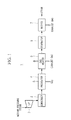
Fig. 1 is a schematic view showing a boiler water supply system according to one embodiment of the present invention. - {
Fig. 2 }
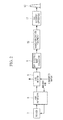
Fig. 2 is a schematic view showing a boiler exhaust system according to one embodiment of the present invention. - {
Fig. 3 }
Fig. 3 is a schematic view showing a CO2 recovery apparatus according to one embodiment of the present invention. - {
Fig. 4 }
Fig. 4 is a schematic view showing a modification of the boiler water supply system according to one embodiment of the present invention. - {
Fig. 5 }
Fig. 5 is a schematic view showing a conventional boiler water supply system. - Hereinafter, a boiler
water supply system 1 according to one embodiment of the present invention will be explained with reference toFig. 1 . - As shown in
Fig. 1 , a boilerwater supply system 1 is constituted by acondenser 3, apreheater 4, agas heater 5 and the like. The boilerwater supply system 1 condenses steam discharged from a low-pressure steam turbine 2 in thecondenser 3, and condensed water condensed and generated by thecondenser 3 is heated to be supplied to aboiler 7. The boiler water supply system is an example of a heat recovery system, which recovers waste heat of a CO2 recovery apparatus 11 and waste heat of exhaust gas etc. when condensed water is heated. - The low-
pressure steam turbine 2 is driven to rotate when medium-pressure steam is supplied from a medium pressure turbine (not shown) for example. The low-pressure steam turbine 2 is connected to a generator (not shown) via a rotation shaft, and a rotary drive force is used for power generation in the generator. The low-pressure steam turbine 2 discharges the generated low-pressure steam to thecondenser 3. - The
condenser 3 condenses low-pressure steam supplied from the low-pressure steam turbine 2. The generated condensed water due to condensation of low-pressure steam in thecondenser 3 is supplied to thepreheater 4. The temperature of the condensed water supplied from thecondenser 3 to thepreheater 4 is, for example, about 38°C. - To the
preheater 4, the condensed water generated in thecondenser 3 is supplied from thecondenser 3. Moreover, to thepreheater 4, CO2 recovered in aregeneration tower 27 of the CO2 recovery apparatus 11 shown inFig. 3 is supplied. In thepreheater 4, heat exchange is performed between the condensed water generated in thecondenser 3 and CO2 recovered in theregeneration tower 27 of the CO2 recovery apparatus 11. The condensed water is heated by passing through thepreheater 4, and the heated condensed water is supplied to thegas heater 5. By doing this, thepreheater 4 can recover waste heat of the CO2 recovery apparatus 11. The temperature of the condensed water supplied from thepreheater 4 to thegas heater 5 is, for example, about 75°C. - To the
gas heater 5, condensed water heated by thepreheater 4 is supplied from thepreheater 4. Moreover, to thegas heater 5, exhaust gas discharged from theboiler 7 is supplied. In thegas heater 5, heat exchange is performed between the condensed water heated in thepreheater 4 and the exhaust gas discharged from theboiler 7. The condensed water is heated by passing through thegas heater 5, and the heated condensed water is supplied to adeaerator 6 connected to theboiler 7. By doing this, thegas heater 5 can recover waste heat of a boiler exhaust system. The temperature of the condensed water supplied from thegas heater 5 to thedeaerator 6 is, for example, about 137°C. - Moreover, the condensed water generated in the
condenser 3 is heated by thepreheater 4 and thegas heater 5, deaerated in thedeaerator 6, and introduced into theboiler 7 as boiler supply water. - As described above, according to the boiler
water supply system 1 according to this embodiment, condensed water generated in thecondenser 3 is subjected to heat exchange with CO2 recovered in theregeneration tower 27 of the CO2 recovery apparatus 11 in thepreheater 4, and subjected to heat exchange with exhaust gas discharged from theboiler 7 in thegas heater 5. As a result, the boilerwater supply system 1 can recover waste heat in the CO2 recovery apparatus 11 and waste heat in the boiler exhaust system. - Moreover, in the above-described boiler
water supply system 1, the entire amount of the condensed water generated in thecondenser 3 is subjected to heat exchange in thepreheater 4 and thegas heater 5, not branched in a path from thecondenser 3 to theboiler 7, and the condensed water is supplied to theboiler 7 as boiler supply water. - Conventionally, when condensed water generated in the
condenser 3 is supplied as boiler supply water to theboiler 7, as shown inFig. 5 , the condensed water has been heated by extracting low-pressure steam from the low-pressure steam turbine 2 and performing heat exchange between the condensed water and the low-pressure steam in a low-pressurefeed water heater 40. In this embodiment, the low-pressurefeed water heater 40 may be omitted by adjusting the temperature condition such that the entire amount of the condensed water generated in thecondenser 3 is supplied to theboiler 7 as boiler supply water. As a result, steam extraction from the low-pressure steam turbine 2 for the low-pressurefeed water heater 40 can be eliminated, and an amount of steam consumption is reduced to improve turbine efficiency. - Next, with reference to
Fig. 2 , the boiler exhaust system according to this embodiment and an installation example of thegas heater 5 in the boiler exhaust system will be explained. - The boiler exhaust system eliminates dust from exhaust gas discharged from the
boiler 7 as well as executes desulfurization, and discharges exhaust gas to ambient air. The boiler exhaust system is constituted by, for example, anair preheater 8, thegas heater 5, a dryelectric dust collector 9, adesulfurization equipment 10, a CO2 recovery apparatus 11 and astack 12. - To the
air preheater 8, ambient air is supplied from the outside. Moreover, to theair preheater 8, exhaust gas discharged from theboiler 7 is supplied. In theair preheater 8, heat exchange is performed between the ambient air to be introduced into theboiler 7 and the exhaust gas discharged from theboiler 7. The exhaust gas passing through theair preheater 8 is cooled and supplied to thegas heater 5. In addition, the ambient air passing through theair preheater 8 is heated and introduced into theboiler 7. - As described before, in the
gas heater 5, heat exchange is performed between the condensed water heated by thepreheater 4 and the exhaust gas discharged from theboiler 7. The exhaust gas passing through thegas heater 5 is cooled and supplied to the dryelectric dust collector 9. Since the exhaust gas passes through theair preheater 8 and thegas heater 5, its temperature is lowered before it is introduced into the dryelectric dust collector 9, which improves removing property of dust and SO3 in the dryelectric dust collector 9. - The dry
electric dust collector 9 removes dust from the cooled exhaust gas. The exhaust gas in which the dust is removed is supplied to thedesulfurization equipment 10. Thedesulfurization equipment 10 mainly absorbs and removes sulfurous acid gas from the exhaust gas and removes dust. The exhaust gas passing through thedesulfurization equipment 10 is introduced into the CO2 recovery apparatus 11. - Moreover, the CO2 recovery apparatus 11 removes CO2 from the exhaust gas. The exhaust gas in which CO2 is removed passes through the
stack 12 to be discharged to ambient air. In addition, CO2 removed from the exhaust gas is compressed to be transmitted to a storage step. - As explained above, the condensed water generated in the
condenser 3 is subjected to heat exchange with the exhaust gas discharged from theboiler 7 in thegas heater 5 of the boiler exhaust system. Additionally, while an arrangement is made in the order of thegas heater 5 and the dryelectric dust collector 9 from the upstream side of the exhaust gas flow in the above-described boiler exhaust system, the present invention is not limited to this example, and for example, an arrangement may be made in the order of the dryelectric dust collector 9 and thegas heater 5 from the upstream side of the exhaust gas flow. - Next, the CO2 recovery apparatus 11 according to this embodiment and an installation example of the
preheater 4 in the CO2 recovery apparatus 11 will be explained with reference toFig. 3 . - In the CO2 recovery apparatus 11,
exhaust gas 20 including CO2 discharged from facilities such as theboiler 7 and a gas turbine (not shown) is supplied tocooling tower 22 by a not shown blower. Theexhaust gas 20 supplied to thecooling tower 22 is cooled by coolingwater 21 in thecooling tower 22. - The cooled
exhaust gas 20 including CO2 is supplied from a lower portion of an absorbingtower 24 via anexhaust gas line 23. In the absorbingtower 24, for example, alkanolamine-based CO2 absorbing liquid 25 (amine solution) is countercurrently contacted to theexhaust gas 20. By doing this, CO2 in theexhaust gas 20 is absorbed in the CO2 absorbing liquid 25, and CO2 is removed from theexhaust gas 20 discharged from an industrial installation. Purgedgas 26 in which CO2 is removed is discharged from atower top portion 24a of the absorbingtower 24. The purgedgas 26 is transmitted to ambient air from the above-describedstack 12. - The CO2 absorbing liquid 25 that absorbs CO2 in the absorbing
tower 24 is stored in atower bottom portion 24b, and transmitted to theregeneration tower 27 by apump 35. - The CO2 absorbing liquid 25 (rich solution) discharges CO2 by being heated by steam generated in a
reboiler 28 in theregeneration tower 27 to be regenerated as CO2 absorbing liquid 25 (lean solution) that can absorb CO2. The regenerated CO2 absorbing liquid 25 is, after it is cooled via aheat exchanger 30 and a leansolution cooling apparatus 31 by apump 29, supplied to the absorbingtower 24 again and reused. - The CO2 discharged from the CO2 absorbing liquid 25 in the
regeneration tower 27 sequentially passes through thepreheater 4, a cooler 32 and a gas-liquid separator 33, is delivered to a CO2 compression apparatus 34 to be compressed, and transmitted to the storage step. - In the
regeneration tower 27 of the CO2 recovery apparatus 11, a multiple stages of (for example, two or three stages) regeneration portions are placed. Each regeneration portion includes anozzle 36 that lowers the CO2 absorbing liquid 25 (rich solution), a packedlayer 37 that countercurrently contacts the CO2 absorbing liquid which is lowered from thenozzle 36 with steam for heating and atray portion 38 that stores the CO2 absorbing liquid 25 (semi-lean solution) in which CO2 is partially removed. - The supply tube L1 supplies the CO2 absorbing liquid 25 (semi-lean solution) stored in the
tray portion 38 of the regeneration portion to the packedlayer 37 of the regeneration portion via thenozzle 36. - The CO2 compression apparatus 34 includes a compressor (not shown) that compresses CO2, a cooler (not shown) that cools the compressed CO2 whose temperature is raised and a gas-liquid separator (not shown). In this embodiment, in the CO2 compression apparatus 34, the
preheater 4 according to this embodiment may be placed in parallel with or instead of the cooler. At this time, in thepreheater 4, heat exchange is performed between the compressed and high-temperature CO2 and the condensed water flowing in the boilerwater supply system 1. The CO2 passing through thepreheater 4 is cooled. On the other hand, the condensed water passing through thepreheater 4 is heated. - As explained above, the condensed water generated in the
condenser 3 is subjected to heat exchange with CO2 discharged from the CO2 absorbing liquid 25 in theregeneration tower 27 or CO2 compressed in the CO2 compression apparatus 34. - Next, a start-up method of the boiler
water supply system 1 according to this embodiment will be explained. - In addition to the above configuration, as shown in
Fig. 3 , a return tube L2 connected to the outlet side and the inlet side of thegas heater 5 is provided to the boilerwater supply system 1, and anauxiliary heater 14 is placed to the return tube L2. Moreover,control valves water supply system 1. Thecontrol valve 15 is placed on the upstream side from a meeting with the return tube L2 on the inlet side of thegas heater 5, and thecontrol valve 16 is placed on the downstream side from a meeting with the return tube L2 on the outlet side of thegas heater 5. - When the temperature of the condensed water supplied from the
condenser 3 is low or an amount of heat capable of heat exchange in thepreheater 4 is small at the time of start-up of the CO2 recovery apparatus 11, the temperature of the gas heater could be excessively lowered. - Accordingly, the temperature of the condensed water at the outlet of the
preheater 4 is detected, and if the detected temperature is lower than a predetermined temperature, the degree of opening of thecontrol valves gas heater 5 to theauxiliary heater 14. Steam is supplied to theauxiliary heater 14, and heat exchange is performed between the supplied steam and the condensed water heated in thegas heater 5. By passing through theauxiliary heater 14, the condensed water is further heated, and thereafter, heated again by thegas heater 5. - Since the condensed water circulates between the
gas heater 5 and theauxiliary heater 14, the temperature of the condensed water to be supplied to thegas heater 5 is raised in a short time. This prevents temperature lowering in a heat exchanger, for example, a fin tube, and corrosion due to sulfuric acid condensation on the surface of fin tube can be prevented. - After that, if the temperature of the condensed water at the outlet of the
preheater 4 is higher than a predetermined temperature, the degree of opening of thecontrol valves auxiliary heater 14. This moves into a normal operation, and the entire amount of the condensed water generated in thecondenser 3 is, after it is subjected to heat exchange in thepreheater 4 and thegas heater 5, supplied to theboiler 7 as boiler supply water. - As described above, in this embodiment, an explanation is made on the configuration that the entire amount of the condensed water generated in the
condenser 3 is subjected to heat exchange in thepreheater 4 and thegas heater 5 and supplied to theboiler 7 as boiler supply water. According to this configuration, as explained above, thepreheater 4 and thegas heater 5 can heat the condensed water instead of the conventional low-pressure feed water heater 40 (seeFig. 5 ). - Especially, in a case where a plant in which the CO2 recovery apparatus 11 and an electric power generation plant including a boiler are placed in parallel is newly installed, since a plant required for steam extraction the low-
pressure steam turbine 2 for the low-pressurefeed water heater 40 is unnecessary, a facility configuration of the plant can be simplified and initial cost can be reduced. - Additionally, the present invention is not limited to a case where the low-pressure
feed water heater 40 is not placed. For example, as shown inFig. 4 , to the boiler water supply system having the low-pressurefeed water heater 40 in the existing electric power facility, the boilerwater supply system 1 according to the this embodiment described above may be placed in parallel. Even in such a case, compared to the conventional boiler water supply system shown inFig. 5 , extracted steam to be supplied from the low-pressure steam turbine 2 to the low-pressurefeed water heater 40 can be reduced, and turbine efficiency can be improved. -
- 1
- boiler water supply system
- 2
- low-pressure steam turbine
- 3
- condenser
- 4
- preheater
- 5
- gas heater
- 6
- deaerator
- 7
- boiler
- 8
- air preheater
- 9
- dry electric dust collector
- 10
- desulfurization equipment
- 11
- CO2 recovery apparatus
- 12
- stack
- 14
- auxiliary heater
- 15, 16
- control valve
- 20
- exhaust gas
- 24
- absorbing tower
- 27
- regeneration tower
- 28
- reboiler
- 34
- CO2 compression apparatus
- 35
- pump
- 40
- low-pressure feed water heater
Claims (6)
- A heat recovery system comprising:a CO2 recovery apparatus which includes an absorbing tower that absorbs CO2 in exhaust gas into absorbing liquid and a regeneration tower that discharges CO2 from the absorbing liquid that absorbed CO2 in the absorbing tower to reuse the absorbing liquid that discharged CO2 in the regeneration tower in the absorbing tower;a steam turbine;a condenser which condenses steam discharged from the steam turbine;a first heat exchange portion in which heat exchange is performed between condensed water generated in the condenser and CO2 recovered in the regeneration tower of the CO2 recovery apparatus;a second heat exchange portion in which heat exchange is performed between the condensed water heated in the first heat exchange portion and exhaust gas discharged from a boiler; andthe boiler to which the condensed water heated in the second heat exchange portion is supplied as boiler supply water.
- The heat recovery system according to claim 1, wherein an entire amount of condensed water generated in the condenser is used as the condensed water subjected to heat exchange in the first heat exchange portion and the second heat exchange portion.
- The heat recovery system according to claim 1, wherein a water supply heater which heats the condensed water generated in the condenser by steam extracted from the steam turbine and supplies the heated condensed water to the boiler is not included.
- The heat recovery system according to claim 1, further comprising a third heat exchange portion which heats the condensed water heated in the second heat exchange portion and returns the heated condensed water to the second heat exchange portion, and
a control portion which switches between the boiler or the third heat exchange portion as a supply destination of the condensed water heated in the second heat exchange portion. - A heat recovery method which uses a CO2 recovery apparatus including an absorbing tower that absorbs CO2 in exhaust gas into absorbing liquid and a regeneration tower that discharges CO2 from the absorbing liquid that absorbs CO2 in the absorbing tower and reuses the absorbing liquid that discharged CO2 in the regeneration tower in the absorbing tower, the method comprising:a first step of condensing steam discharged from a steam turbine;a second step of performing heat exchange between generated condensed water and CO2 recovered in the regeneration tower of the CO2 recovery apparatus in a first heat exchange portion;a third step of performing heat exchange between the condensed water heated in the first heat exchange portion and exhaust gas discharged from a boiler in a second heat exchange portion; anda fourth step of supplying the condensed water heated in the second heat exchange portion to the boiler as boiler supply water.
- The heat recovery method according to claim 5, further comprising a fifth step of heating the condensed water heated in the second heat exchange portion in a third heat exchange portion which is different from the boiler and heating the condensed water heated in the third heat exchange portion in the second heat exchange portion.
Applications Claiming Priority (2)
| Application Number | Priority Date | Filing Date | Title |
|---|---|---|---|
| US13/605,199 US20140060459A1 (en) | 2012-09-06 | 2012-09-06 | Heat recovery system and heat recovery method |
| PCT/JP2013/072614 WO2014038412A1 (en) | 2012-09-06 | 2013-08-23 | Heat recovery system and heat recovery method |
Publications (3)
| Publication Number | Publication Date |
|---|---|
| EP2899462A1 true EP2899462A1 (en) | 2015-07-29 |
| EP2899462A4 EP2899462A4 (en) | 2016-06-15 |
| EP2899462B1 EP2899462B1 (en) | 2018-11-14 |
Family
ID=50185673
Family Applications (1)
| Application Number | Title | Priority Date | Filing Date |
|---|---|---|---|
| EP13835786.8A Active EP2899462B1 (en) | 2012-09-06 | 2013-08-23 | Heat recovery system and heat recovery method |
Country Status (6)
| Country | Link |
|---|---|
| US (1) | US20140060459A1 (en) |
| EP (1) | EP2899462B1 (en) |
| JP (1) | JP5976817B2 (en) |
| AU (1) | AU2013313605B2 (en) |
| CA (1) | CA2883111C (en) |
| WO (1) | WO2014038412A1 (en) |
Families Citing this family (5)
| Publication number | Priority date | Publication date | Assignee | Title |
|---|---|---|---|---|
| PL2942494T3 (en) * | 2014-05-08 | 2020-03-31 | General Electric Technology Gmbh | Coal fired oxy plant with heat integration |
| US10378763B2 (en) * | 2015-12-03 | 2019-08-13 | General Electric Company | Method and apparatus to facilitate heating feedwater in a power generation system |
| JP6576288B2 (en) * | 2016-04-01 | 2019-09-18 | 日鉄エンジニアリング株式会社 | Carbon dioxide gas recovery device and carbon dioxide gas manufacturing method |
| CN107191232B (en) * | 2017-06-06 | 2023-07-07 | 大唐东北电力试验研究所有限公司 | Heating system of electric heating unit |
| CN107559861B (en) * | 2017-09-08 | 2024-11-05 | 清华大学 | Three-tower heat exchange method and device based on boiler exhaust condensate heat transfer cycle |
Family Cites Families (20)
| Publication number | Priority date | Publication date | Assignee | Title |
|---|---|---|---|---|
| US3818872A (en) * | 1973-06-29 | 1974-06-25 | Combustion Eng | Economizer bypass for increased furnace wall protection |
| US4057966A (en) * | 1975-08-12 | 1977-11-15 | Evgeny Nikolaevich Prutkovsky | Steam-gas power plant |
| DE4335216C2 (en) * | 1993-05-10 | 2003-04-24 | Saar En Gmbh | Steam power plant for generating electrical energy |
| JPH07286703A (en) * | 1994-04-18 | 1995-10-31 | Babcock Hitachi Kk | Pressurized fluidized-bed boiler composite power plant and operating method therefor |
| JPH07293808A (en) * | 1994-04-22 | 1995-11-10 | Toshiba Corp | Water heater controller |
| JPH0932507A (en) * | 1995-07-19 | 1997-02-04 | Mitsubishi Heavy Ind Ltd | Control method of exhaust re-combustion type combined plant |
| JPH09152103A (en) * | 1995-11-29 | 1997-06-10 | Mitsubishi Heavy Ind Ltd | Waste heat recovery boiler |
| DE19926326A1 (en) * | 1999-06-09 | 2000-12-14 | Abb Alstom Power Ch Ag | Process and plant for heating a liquid medium |
| US7615200B2 (en) * | 2000-12-01 | 2009-11-10 | Fuel Tech, Inc. | Selective catalytic reduction of NOx enabled by urea decomposition in heat-exchanger bypass |
| US7353660B2 (en) * | 2004-09-13 | 2008-04-08 | Carrier Corporation | Multi-temperature cooling system with unloading |
| JP4959156B2 (en) | 2004-11-29 | 2012-06-20 | 三菱重工業株式会社 | Heat recovery equipment |
| JP4875303B2 (en) | 2005-02-07 | 2012-02-15 | 三菱重工業株式会社 | Carbon dioxide recovery system, power generation system using the same, and methods thereof |
| US20100199670A1 (en) * | 2009-02-06 | 2010-08-12 | Siemens Energy, Inc. | Power Generation Plant Having Inert Gas Deaerator and Associated Methods |
| JP5148546B2 (en) * | 2009-04-09 | 2013-02-20 | 三菱重工業株式会社 | Heat recovery equipment |
| DE102009032537A1 (en) * | 2009-07-10 | 2011-01-13 | Hitachi Power Europe Gmbh | Coal-fired power station with associated CO2 scrubbing and heat recovery |
| US20110120128A1 (en) * | 2009-11-20 | 2011-05-26 | Alstom Technology Ltd | Method of controlling a power plant |
| JP5260585B2 (en) * | 2010-03-12 | 2013-08-14 | 株式会社日立製作所 | Coal-fired power plant and method for operating coal-fired power plant |
| JP5639814B2 (en) * | 2010-08-10 | 2014-12-10 | バブコック日立株式会社 | Thermal power generation system with CO2 removal equipment |
| JP5489254B2 (en) * | 2010-09-29 | 2014-05-14 | バブコック日立株式会社 | Oxyfuel combustion system and operating method thereof |
| JP5637808B2 (en) * | 2010-10-21 | 2014-12-10 | 株式会社東芝 | Carbon dioxide recovery method and carbon dioxide recovery steam power generation system |
-
2012
- 2012-09-06 US US13/605,199 patent/US20140060459A1/en not_active Abandoned
-
2013
- 2013-08-23 JP JP2014534287A patent/JP5976817B2/en active Active
- 2013-08-23 AU AU2013313605A patent/AU2013313605B2/en active Active
- 2013-08-23 WO PCT/JP2013/072614 patent/WO2014038412A1/en not_active Ceased
- 2013-08-23 EP EP13835786.8A patent/EP2899462B1/en active Active
- 2013-08-23 CA CA2883111A patent/CA2883111C/en active Active
Also Published As
| Publication number | Publication date |
|---|---|
| JPWO2014038412A1 (en) | 2016-08-08 |
| JP5976817B2 (en) | 2016-08-24 |
| EP2899462B1 (en) | 2018-11-14 |
| CA2883111C (en) | 2018-02-20 |
| AU2013313605A1 (en) | 2015-03-12 |
| WO2014038412A1 (en) | 2014-03-13 |
| AU2013313605B2 (en) | 2016-08-18 |
| CA2883111A1 (en) | 2014-03-13 |
| EP2899462A4 (en) | 2016-06-15 |
| US20140060459A1 (en) | 2014-03-06 |
Similar Documents
| Publication | Publication Date | Title |
|---|---|---|
| JP5643691B2 (en) | Carbon dioxide recovery steam power generation system and operation method thereof | |
| US8347627B2 (en) | Carbon-dioxide-capture-type steam power generation system | |
| JP4274846B2 (en) | Carbon dioxide recovery method and system | |
| US8720203B2 (en) | Carbon dioxide recovery method and carbon-dioxide-recovery-type steam power generation system | |
| US9383101B2 (en) | CO2 recovery unit and CO2 recovery method | |
| AU2020316185B2 (en) | Gas turbine plant | |
| JP7356345B2 (en) | Exhaust gas treatment equipment and gas turbine plants | |
| US20120216540A1 (en) | Coal power plant having an associated co2 scrubbing station and heat recovery | |
| EP2899462B1 (en) | Heat recovery system and heat recovery method | |
| EP2444599A2 (en) | Carbon dioxide recovery method and carbon- dioxide-recovery-type steam power generation system | |
| WO2013114937A1 (en) | Carbon dioxide recovery system | |
| JP7491760B2 (en) | Gas Turbine Plant | |
| CN103906557A (en) | Method and system for removing carbon dioxide from flue gases | |
| US20250345746A1 (en) | Exhaust gas processing equipment and gas turbine plant |
Legal Events
| Date | Code | Title | Description |
|---|---|---|---|
| PUAI | Public reference made under article 153(3) epc to a published international application that has entered the european phase |
Free format text: ORIGINAL CODE: 0009012 |
|
| 17P | Request for examination filed |
Effective date: 20150303 |
|
| AK | Designated contracting states |
Kind code of ref document: A1 Designated state(s): AL AT BE BG CH CY CZ DE DK EE ES FI FR GB GR HR HU IE IS IT LI LT LU LV MC MK MT NL NO PL PT RO RS SE SI SK SM TR |
|
| AX | Request for extension of the european patent |
Extension state: BA ME |
|
| DAX | Request for extension of the european patent (deleted) | ||
| RA4 | Supplementary search report drawn up and despatched (corrected) |
Effective date: 20160512 |
|
| RIC1 | Information provided on ipc code assigned before grant |
Ipc: F22D 1/18 20060101AFI20160506BHEP Ipc: F22D 1/02 20060101ALI20160506BHEP Ipc: F22D 1/00 20060101ALI20160506BHEP |
|
| STAA | Information on the status of an ep patent application or granted ep patent |
Free format text: STATUS: EXAMINATION IS IN PROGRESS |
|
| 17Q | First examination report despatched |
Effective date: 20170407 |
|
| GRAP | Despatch of communication of intention to grant a patent |
Free format text: ORIGINAL CODE: EPIDOSNIGR1 |
|
| STAA | Information on the status of an ep patent application or granted ep patent |
Free format text: STATUS: GRANT OF PATENT IS INTENDED |
|
| INTG | Intention to grant announced |
Effective date: 20180608 |
|
| RAP1 | Party data changed (applicant data changed or rights of an application transferred) |
Owner name: MITSUBISHI HEAVY INDUSTRIES ENGINEERING, LTD. |
|
| GRAS | Grant fee paid |
Free format text: ORIGINAL CODE: EPIDOSNIGR3 |
|
| GRAA | (expected) grant |
Free format text: ORIGINAL CODE: 0009210 |
|
| STAA | Information on the status of an ep patent application or granted ep patent |
Free format text: STATUS: THE PATENT HAS BEEN GRANTED |
|
| AK | Designated contracting states |
Kind code of ref document: B1 Designated state(s): AL AT BE BG CH CY CZ DE DK EE ES FI FR GB GR HR HU IE IS IT LI LT LU LV MC MK MT NL NO PL PT RO RS SE SI SK SM TR |
|
| REG | Reference to a national code |
Ref country code: CH Ref legal event code: EP Ref country code: AT Ref legal event code: REF Ref document number: 1065261 Country of ref document: AT Kind code of ref document: T Effective date: 20181115 |
|
| REG | Reference to a national code |
Ref country code: DE Ref legal event code: R096 Ref document number: 602013046861 Country of ref document: DE |
|
| REG | Reference to a national code |
Ref country code: IE Ref legal event code: FG4D |
|
| REG | Reference to a national code |
Ref country code: NL Ref legal event code: FP |
|
| REG | Reference to a national code |
Ref country code: NO Ref legal event code: T2 Effective date: 20181114 |
|
| REG | Reference to a national code |
Ref country code: LT Ref legal event code: MG4D |
|
| REG | Reference to a national code |
Ref country code: AT Ref legal event code: MK05 Ref document number: 1065261 Country of ref document: AT Kind code of ref document: T Effective date: 20181114 |
|
| PG25 | Lapsed in a contracting state [announced via postgrant information from national office to epo] |
Ref country code: LT Free format text: LAPSE BECAUSE OF FAILURE TO SUBMIT A TRANSLATION OF THE DESCRIPTION OR TO PAY THE FEE WITHIN THE PRESCRIBED TIME-LIMIT Effective date: 20181114 Ref country code: HR Free format text: LAPSE BECAUSE OF FAILURE TO SUBMIT A TRANSLATION OF THE DESCRIPTION OR TO PAY THE FEE WITHIN THE PRESCRIBED TIME-LIMIT Effective date: 20181114 Ref country code: LV Free format text: LAPSE BECAUSE OF FAILURE TO SUBMIT A TRANSLATION OF THE DESCRIPTION OR TO PAY THE FEE WITHIN THE PRESCRIBED TIME-LIMIT Effective date: 20181114 Ref country code: IS Free format text: LAPSE BECAUSE OF FAILURE TO SUBMIT A TRANSLATION OF THE DESCRIPTION OR TO PAY THE FEE WITHIN THE PRESCRIBED TIME-LIMIT Effective date: 20190314 Ref country code: FI Free format text: LAPSE BECAUSE OF FAILURE TO SUBMIT A TRANSLATION OF THE DESCRIPTION OR TO PAY THE FEE WITHIN THE PRESCRIBED TIME-LIMIT Effective date: 20181114 Ref country code: AT Free format text: LAPSE BECAUSE OF FAILURE TO SUBMIT A TRANSLATION OF THE DESCRIPTION OR TO PAY THE FEE WITHIN THE PRESCRIBED TIME-LIMIT Effective date: 20181114 Ref country code: ES Free format text: LAPSE BECAUSE OF FAILURE TO SUBMIT A TRANSLATION OF THE DESCRIPTION OR TO PAY THE FEE WITHIN THE PRESCRIBED TIME-LIMIT Effective date: 20181114 Ref country code: BG Free format text: LAPSE BECAUSE OF FAILURE TO SUBMIT A TRANSLATION OF THE DESCRIPTION OR TO PAY THE FEE WITHIN THE PRESCRIBED TIME-LIMIT Effective date: 20190214 |
|
| PG25 | Lapsed in a contracting state [announced via postgrant information from national office to epo] |
Ref country code: AL Free format text: LAPSE BECAUSE OF FAILURE TO SUBMIT A TRANSLATION OF THE DESCRIPTION OR TO PAY THE FEE WITHIN THE PRESCRIBED TIME-LIMIT Effective date: 20181114 Ref country code: PT Free format text: LAPSE BECAUSE OF FAILURE TO SUBMIT A TRANSLATION OF THE DESCRIPTION OR TO PAY THE FEE WITHIN THE PRESCRIBED TIME-LIMIT Effective date: 20190314 Ref country code: SE Free format text: LAPSE BECAUSE OF FAILURE TO SUBMIT A TRANSLATION OF THE DESCRIPTION OR TO PAY THE FEE WITHIN THE PRESCRIBED TIME-LIMIT Effective date: 20181114 Ref country code: GR Free format text: LAPSE BECAUSE OF FAILURE TO SUBMIT A TRANSLATION OF THE DESCRIPTION OR TO PAY THE FEE WITHIN THE PRESCRIBED TIME-LIMIT Effective date: 20190215 Ref country code: RS Free format text: LAPSE BECAUSE OF FAILURE TO SUBMIT A TRANSLATION OF THE DESCRIPTION OR TO PAY THE FEE WITHIN THE PRESCRIBED TIME-LIMIT Effective date: 20181114 |
|
| PG25 | Lapsed in a contracting state [announced via postgrant information from national office to epo] |
Ref country code: PL Free format text: LAPSE BECAUSE OF FAILURE TO SUBMIT A TRANSLATION OF THE DESCRIPTION OR TO PAY THE FEE WITHIN THE PRESCRIBED TIME-LIMIT Effective date: 20181114 Ref country code: CZ Free format text: LAPSE BECAUSE OF FAILURE TO SUBMIT A TRANSLATION OF THE DESCRIPTION OR TO PAY THE FEE WITHIN THE PRESCRIBED TIME-LIMIT Effective date: 20181114 Ref country code: DK Free format text: LAPSE BECAUSE OF FAILURE TO SUBMIT A TRANSLATION OF THE DESCRIPTION OR TO PAY THE FEE WITHIN THE PRESCRIBED TIME-LIMIT Effective date: 20181114 |
|
| REG | Reference to a national code |
Ref country code: DE Ref legal event code: R097 Ref document number: 602013046861 Country of ref document: DE |
|
| PG25 | Lapsed in a contracting state [announced via postgrant information from national office to epo] |
Ref country code: EE Free format text: LAPSE BECAUSE OF FAILURE TO SUBMIT A TRANSLATION OF THE DESCRIPTION OR TO PAY THE FEE WITHIN THE PRESCRIBED TIME-LIMIT Effective date: 20181114 Ref country code: SM Free format text: LAPSE BECAUSE OF FAILURE TO SUBMIT A TRANSLATION OF THE DESCRIPTION OR TO PAY THE FEE WITHIN THE PRESCRIBED TIME-LIMIT Effective date: 20181114 Ref country code: SK Free format text: LAPSE BECAUSE OF FAILURE TO SUBMIT A TRANSLATION OF THE DESCRIPTION OR TO PAY THE FEE WITHIN THE PRESCRIBED TIME-LIMIT Effective date: 20181114 Ref country code: RO Free format text: LAPSE BECAUSE OF FAILURE TO SUBMIT A TRANSLATION OF THE DESCRIPTION OR TO PAY THE FEE WITHIN THE PRESCRIBED TIME-LIMIT Effective date: 20181114 |
|
| PLBE | No opposition filed within time limit |
Free format text: ORIGINAL CODE: 0009261 |
|
| STAA | Information on the status of an ep patent application or granted ep patent |
Free format text: STATUS: NO OPPOSITION FILED WITHIN TIME LIMIT |
|
| 26N | No opposition filed |
Effective date: 20190815 |
|
| PG25 | Lapsed in a contracting state [announced via postgrant information from national office to epo] |
Ref country code: SI Free format text: LAPSE BECAUSE OF FAILURE TO SUBMIT A TRANSLATION OF THE DESCRIPTION OR TO PAY THE FEE WITHIN THE PRESCRIBED TIME-LIMIT Effective date: 20181114 |
|
| PG25 | Lapsed in a contracting state [announced via postgrant information from national office to epo] |
Ref country code: TR Free format text: LAPSE BECAUSE OF FAILURE TO SUBMIT A TRANSLATION OF THE DESCRIPTION OR TO PAY THE FEE WITHIN THE PRESCRIBED TIME-LIMIT Effective date: 20181114 |
|
| PG25 | Lapsed in a contracting state [announced via postgrant information from national office to epo] |
Ref country code: CH Free format text: LAPSE BECAUSE OF NON-PAYMENT OF DUE FEES Effective date: 20190831 Ref country code: LI Free format text: LAPSE BECAUSE OF NON-PAYMENT OF DUE FEES Effective date: 20190831 Ref country code: LU Free format text: LAPSE BECAUSE OF NON-PAYMENT OF DUE FEES Effective date: 20190823 Ref country code: MC Free format text: LAPSE BECAUSE OF FAILURE TO SUBMIT A TRANSLATION OF THE DESCRIPTION OR TO PAY THE FEE WITHIN THE PRESCRIBED TIME-LIMIT Effective date: 20181114 |
|
| REG | Reference to a national code |
Ref country code: BE Ref legal event code: MM Effective date: 20190831 |
|
| PG25 | Lapsed in a contracting state [announced via postgrant information from national office to epo] |
Ref country code: FR Free format text: LAPSE BECAUSE OF NON-PAYMENT OF DUE FEES Effective date: 20190831 Ref country code: IE Free format text: LAPSE BECAUSE OF NON-PAYMENT OF DUE FEES Effective date: 20190823 |
|
| PG25 | Lapsed in a contracting state [announced via postgrant information from national office to epo] |
Ref country code: BE Free format text: LAPSE BECAUSE OF NON-PAYMENT OF DUE FEES Effective date: 20190831 |
|
| PG25 | Lapsed in a contracting state [announced via postgrant information from national office to epo] |
Ref country code: CY Free format text: LAPSE BECAUSE OF FAILURE TO SUBMIT A TRANSLATION OF THE DESCRIPTION OR TO PAY THE FEE WITHIN THE PRESCRIBED TIME-LIMIT Effective date: 20181114 |
|
| PG25 | Lapsed in a contracting state [announced via postgrant information from national office to epo] |
Ref country code: HU Free format text: LAPSE BECAUSE OF FAILURE TO SUBMIT A TRANSLATION OF THE DESCRIPTION OR TO PAY THE FEE WITHIN THE PRESCRIBED TIME-LIMIT; INVALID AB INITIO Effective date: 20130823 Ref country code: MT Free format text: LAPSE BECAUSE OF FAILURE TO SUBMIT A TRANSLATION OF THE DESCRIPTION OR TO PAY THE FEE WITHIN THE PRESCRIBED TIME-LIMIT Effective date: 20181114 |
|
| PG25 | Lapsed in a contracting state [announced via postgrant information from national office to epo] |
Ref country code: MK Free format text: LAPSE BECAUSE OF FAILURE TO SUBMIT A TRANSLATION OF THE DESCRIPTION OR TO PAY THE FEE WITHIN THE PRESCRIBED TIME-LIMIT Effective date: 20181114 |
|
| P01 | Opt-out of the competence of the unified patent court (upc) registered |
Effective date: 20230522 |
|
| REG | Reference to a national code |
Ref country code: DE Ref legal event code: R081 Ref document number: 602013046861 Country of ref document: DE Owner name: MITSUBISHI HEAVY INDUSTRIES, LTD., JP Free format text: FORMER OWNER: MITSUBISHI HEAVY INDUSTRIES ENGINEERING, LTD., YOKOHAMA-SHI, KANAGAWA, JP |
|
| REG | Reference to a national code |
Ref country code: DE Ref legal event code: R081 Ref document number: 602013046861 Country of ref document: DE Owner name: MITSUBISHI HEAVY INDUSTRIES, LTD., JP Free format text: FORMER OWNER: MHI ENGINEERING, LTD., YOKOHAMA-SHI, KANAGAWA, JP |
|
| REG | Reference to a national code |
Ref country code: NL Ref legal event code: PD Owner name: MITSUBISHI HEAVY INDUSTRIES, LTD.; JP Free format text: DETAILS ASSIGNMENT: CHANGE OF OWNER(S), ASSIGNMENT; FORMER OWNER NAME: MHI ENGINEERING, LTD. Effective date: 20231206 Ref country code: NL Ref legal event code: HC Owner name: MHI ENGINEERING, LTD.; JP Free format text: DETAILS ASSIGNMENT: CHANGE OF OWNER(S), CHANGE OF OWNER(S) NAME; FORMER OWNER NAME: MITSUBISHI HEAVY INDUSTRIES ENGINEERING, LTD. Effective date: 20231206 |
|
| REG | Reference to a national code |
Ref country code: GB Ref legal event code: 732E Free format text: REGISTERED BETWEEN 20240404 AND 20240410 |
|
| PGFP | Annual fee paid to national office [announced via postgrant information from national office to epo] |
Ref country code: NL Payment date: 20250704 Year of fee payment: 13 |
|
| PGFP | Annual fee paid to national office [announced via postgrant information from national office to epo] |
Ref country code: DE Payment date: 20250702 Year of fee payment: 13 |
|
| PGFP | Annual fee paid to national office [announced via postgrant information from national office to epo] |
Ref country code: NO Payment date: 20250808 Year of fee payment: 13 |
|
| PGFP | Annual fee paid to national office [announced via postgrant information from national office to epo] |
Ref country code: IT Payment date: 20250722 Year of fee payment: 13 |
|
| PGFP | Annual fee paid to national office [announced via postgrant information from national office to epo] |
Ref country code: GB Payment date: 20250703 Year of fee payment: 13 |