EP2899425A1 - B-directional hydraulic flow control valve - Google Patents
B-directional hydraulic flow control valve Download PDFInfo
- Publication number
- EP2899425A1 EP2899425A1 EP14196448.6A EP14196448A EP2899425A1 EP 2899425 A1 EP2899425 A1 EP 2899425A1 EP 14196448 A EP14196448 A EP 14196448A EP 2899425 A1 EP2899425 A1 EP 2899425A1
- Authority
- EP
- European Patent Office
- Prior art keywords
- spring
- valve according
- valve
- flow
- piston
- Prior art date
- Legal status (The legal status is an assumption and is not a legal conclusion. Google has not performed a legal analysis and makes no representation as to the accuracy of the status listed.)
- Granted
Links
- 239000000725 suspension Substances 0.000 claims abstract description 31
- 230000036316 preload Effects 0.000 claims description 4
- 239000012530 fluid Substances 0.000 description 22
- 230000006835 compression Effects 0.000 description 4
- 238000007906 compression Methods 0.000 description 4
- 238000013016 damping Methods 0.000 description 3
- 238000005452 bending Methods 0.000 description 2
- 230000000694 effects Effects 0.000 description 2
- 239000007789 gas Substances 0.000 description 2
- IJGRMHOSHXDMSA-UHFFFAOYSA-N Atomic nitrogen Chemical compound N#N IJGRMHOSHXDMSA-UHFFFAOYSA-N 0.000 description 1
- 229910000639 Spring steel Inorganic materials 0.000 description 1
- XAGFODPZIPBFFR-UHFFFAOYSA-N aluminium Chemical compound [Al] XAGFODPZIPBFFR-UHFFFAOYSA-N 0.000 description 1
- 229910052782 aluminium Inorganic materials 0.000 description 1
- 239000004411 aluminium Substances 0.000 description 1
- 230000000903 blocking effect Effects 0.000 description 1
- 238000010276 construction Methods 0.000 description 1
- 238000004512 die casting Methods 0.000 description 1
- 229910001873 dinitrogen Inorganic materials 0.000 description 1
- 238000005553 drilling Methods 0.000 description 1
- 239000010720 hydraulic oil Substances 0.000 description 1
- 239000007788 liquid Substances 0.000 description 1
- 238000004519 manufacturing process Methods 0.000 description 1
- 239000003921 oil Substances 0.000 description 1
- 230000010355 oscillation Effects 0.000 description 1
- 230000000717 retained effect Effects 0.000 description 1
- 238000007789 sealing Methods 0.000 description 1
- 238000011144 upstream manufacturing Methods 0.000 description 1
- XLYOFNOQVPJJNP-UHFFFAOYSA-N water Substances O XLYOFNOQVPJJNP-UHFFFAOYSA-N 0.000 description 1
Images

Classifications
-
- F—MECHANICAL ENGINEERING; LIGHTING; HEATING; WEAPONS; BLASTING
- F16—ENGINEERING ELEMENTS AND UNITS; GENERAL MEASURES FOR PRODUCING AND MAINTAINING EFFECTIVE FUNCTIONING OF MACHINES OR INSTALLATIONS; THERMAL INSULATION IN GENERAL
- F16F—SPRINGS; SHOCK-ABSORBERS; MEANS FOR DAMPING VIBRATION
- F16F9/00—Springs, vibration-dampers, shock-absorbers, or similarly-constructed movement-dampers using a fluid or the equivalent as damping medium
- F16F9/32—Details
- F16F9/34—Special valve constructions; Shape or construction of throttling passages
- F16F9/3405—Throttling passages in or on piston body, e.g. slots
-
- F—MECHANICAL ENGINEERING; LIGHTING; HEATING; WEAPONS; BLASTING
- F16—ENGINEERING ELEMENTS AND UNITS; GENERAL MEASURES FOR PRODUCING AND MAINTAINING EFFECTIVE FUNCTIONING OF MACHINES OR INSTALLATIONS; THERMAL INSULATION IN GENERAL
- F16K—VALVES; TAPS; COCKS; ACTUATING-FLOATS; DEVICES FOR VENTING OR AERATING
- F16K15/00—Check valves
- F16K15/02—Check valves with guided rigid valve members
- F16K15/025—Check valves with guided rigid valve members the valve being loaded by a spring
- F16K15/026—Check valves with guided rigid valve members the valve being loaded by a spring the valve member being a movable body around which the medium flows when the valve is open
-
- B—PERFORMING OPERATIONS; TRANSPORTING
- B60—VEHICLES IN GENERAL
- B60G—VEHICLE SUSPENSION ARRANGEMENTS
- B60G17/00—Resilient suspensions having means for adjusting the spring or vibration-damper characteristics, for regulating the distance between a supporting surface and a sprung part of vehicle or for locking suspension during use to meet varying vehicular or surface conditions, e.g. due to speed or load
- B60G17/06—Characteristics of dampers, e.g. mechanical dampers
- B60G17/08—Characteristics of fluid dampers
-
- F—MECHANICAL ENGINEERING; LIGHTING; HEATING; WEAPONS; BLASTING
- F16—ENGINEERING ELEMENTS AND UNITS; GENERAL MEASURES FOR PRODUCING AND MAINTAINING EFFECTIVE FUNCTIONING OF MACHINES OR INSTALLATIONS; THERMAL INSULATION IN GENERAL
- F16F—SPRINGS; SHOCK-ABSORBERS; MEANS FOR DAMPING VIBRATION
- F16F9/00—Springs, vibration-dampers, shock-absorbers, or similarly-constructed movement-dampers using a fluid or the equivalent as damping medium
- F16F9/32—Details
- F16F9/34—Special valve constructions; Shape or construction of throttling passages
- F16F9/348—Throttling passages in the form of annular discs or other plate-like elements which may or may not have a spring action, operating in opposite directions or singly, e.g. annular discs positioned on top of the valve or piston body
- F16F9/3485—Throttling passages in the form of annular discs or other plate-like elements which may or may not have a spring action, operating in opposite directions or singly, e.g. annular discs positioned on top of the valve or piston body characterised by features of supporting elements intended to guide or limit the movement of the annular discs
-
- F—MECHANICAL ENGINEERING; LIGHTING; HEATING; WEAPONS; BLASTING
- F16—ENGINEERING ELEMENTS AND UNITS; GENERAL MEASURES FOR PRODUCING AND MAINTAINING EFFECTIVE FUNCTIONING OF MACHINES OR INSTALLATIONS; THERMAL INSULATION IN GENERAL
- F16F—SPRINGS; SHOCK-ABSORBERS; MEANS FOR DAMPING VIBRATION
- F16F9/00—Springs, vibration-dampers, shock-absorbers, or similarly-constructed movement-dampers using a fluid or the equivalent as damping medium
- F16F9/32—Details
- F16F9/34—Special valve constructions; Shape or construction of throttling passages
- F16F9/348—Throttling passages in the form of annular discs or other plate-like elements which may or may not have a spring action, operating in opposite directions or singly, e.g. annular discs positioned on top of the valve or piston body
- F16F9/3488—Throttling passages in the form of annular discs or other plate-like elements which may or may not have a spring action, operating in opposite directions or singly, e.g. annular discs positioned on top of the valve or piston body characterised by features intended to affect valve bias or pre-stress
-
- F—MECHANICAL ENGINEERING; LIGHTING; HEATING; WEAPONS; BLASTING
- F16—ENGINEERING ELEMENTS AND UNITS; GENERAL MEASURES FOR PRODUCING AND MAINTAINING EFFECTIVE FUNCTIONING OF MACHINES OR INSTALLATIONS; THERMAL INSULATION IN GENERAL
- F16F—SPRINGS; SHOCK-ABSORBERS; MEANS FOR DAMPING VIBRATION
- F16F9/00—Springs, vibration-dampers, shock-absorbers, or similarly-constructed movement-dampers using a fluid or the equivalent as damping medium
- F16F9/32—Details
- F16F9/50—Special means providing automatic damping adjustment, i.e. self-adjustment of damping by particular sliding movements of a valve element, other than flexions or displacement of valve discs; Special means providing self-adjustment of spring characteristics
- F16F9/512—Means responsive to load action, i.e. static load on the damper or dynamic fluid pressure changes in the damper, e.g. due to changes in velocity
- F16F9/5126—Piston, or piston-like valve elements
-
- B—PERFORMING OPERATIONS; TRANSPORTING
- B60—VEHICLES IN GENERAL
- B60G—VEHICLE SUSPENSION ARRANGEMENTS
- B60G2202/00—Indexing codes relating to the type of spring, damper or actuator
- B60G2202/20—Type of damper
- B60G2202/24—Fluid damper
-
- B—PERFORMING OPERATIONS; TRANSPORTING
- B60—VEHICLES IN GENERAL
- B60G—VEHICLE SUSPENSION ARRANGEMENTS
- B60G2500/00—Indexing codes relating to the regulated action or device
- B60G2500/10—Damping action or damper
- B60G2500/11—Damping valves
- B60G2500/112—Fluid actuation
-
- B—PERFORMING OPERATIONS; TRANSPORTING
- B60—VEHICLES IN GENERAL
- B60G—VEHICLE SUSPENSION ARRANGEMENTS
- B60G2800/00—Indexing codes relating to the type of movement or to the condition of the vehicle and to the end result to be achieved by the control action
- B60G2800/16—Running
- B60G2800/162—Reducing road induced vibrations
-
- Y—GENERAL TAGGING OF NEW TECHNOLOGICAL DEVELOPMENTS; GENERAL TAGGING OF CROSS-SECTIONAL TECHNOLOGIES SPANNING OVER SEVERAL SECTIONS OF THE IPC; TECHNICAL SUBJECTS COVERED BY FORMER USPC CROSS-REFERENCE ART COLLECTIONS [XRACs] AND DIGESTS
- Y10—TECHNICAL SUBJECTS COVERED BY FORMER USPC
- Y10T—TECHNICAL SUBJECTS COVERED BY FORMER US CLASSIFICATION
- Y10T137/00—Fluid handling
- Y10T137/7722—Line condition change responsive valves
- Y10T137/7837—Direct response valves [i.e., check valve type]
- Y10T137/7904—Reciprocating valves
- Y10T137/7922—Spring biased
- Y10T137/7929—Spring coaxial with valve
Definitions
- the present invention relates to a control valve of a hydraulic duct, the valve being adapted to control hydraulic flow in both directions through the duct.
- Hydraulic systems rely upon flow of a hydraulic fluid, typically an oil or water based liquid, to achieve a desired effect.
- a hydraulic fluid typically an oil or water based liquid
- a hydropneumatic suspension of a vehicle in which road wheels are mounted on respective hydraulic actuators, and springing is provided by a hydropneumatic suspension module containing a springing medium, such as nitrogen gas.
- Suspension modules are typically in the form of a sphere having a diaphragm separating hydraulic fluid from a suspension gas under pressure. Working of the suspension causes movement of hydraulic fluid to and from the sphere.
- Such suspension systems are well known and need not be further described here.
- Some kinds of vehicle, particularly agricultural and construction vehicles, are designed to operate both on and off highway.
- the respective ranges of suspension movement are significantly different, so that a suspension optimized for on-highway use may be too hard for off-highway use.
- a suspension capable of accommodating wheel deflections in off-highway use may be uncomfortably soft in on-highway conditions. In either case the speed of travel of a vehicle may be severely limited if used on terrain for which the suspension is not optimized.
- a driver selectable alternative increases expense and complication, and is preferably avoided.
- a flow control valve for a hydraulic conduit, said valve comprising a valve body having an open through passage defining a flow restriction, and an arcuate array of flow relief passages, each of said relief passages having at one side a closure comprising a leaf spring, and at least one said leaf spring being provided at each side of the valve body, wherein said valve includes a piston reciprocal in said body, said piston having end abutments to limit travel thereof, said piston being resiliently biased in one direction to permit said one end abutment to seat a corresponding leaf spring at one side of said body, and being movable under increasing hydraulic pressure to unseat said corresponding leaf spring, thereby to open a respective relief passage.
- Such a bi-directional valve is substantially symmetrical and relatively straightforward to manufacture whilst being tunable for both bump and rebound.
- the open through passage may be provided in said piston, for example as an axial opening of a substantial annular piston.
- the array of relief passage may be circular and equispaced.
- the leaf springs may be circular and annular, and the lip thereof may lift under pressure to provide a first relief opening.
- a second relief opening is provided by sliding motion of the piston within the body.
- a double acting relief valve has two-stage relief available for both directions of hydraulic flow (bump and rebound), both stages on each side being independently tunable.
- Such a valve provides damping and flow relief suitable for on-highway travel, yet can provide for additional suspension travel in off-highway travel whilst maintaining an acceptable ride and handling characteristic at speed.
- a vehicle 11 has a wheel 12 connected thereto by a pivotable suspension arm 13.
- a hydraulic strut 14 permits suspension movement of the wheel and is coupled via a hydraulic line 15 to a suspension sphere 16 having an internal diaphragm 17 confining pressurized gas 18 on one side thereof.
- a fluid restrictor 19 provides damping of the movement of hydraulic fluid as the suspension is worked.
- Fig. 1 illustrates a strut 14 by way of example, but any suitable actuator or motor may be used.
- FIG. 2-4 A cylindrical body 21 fits closely within a hydraulic duct 22, and has four equispaced through apertures 23.
- the opposite end faces of the body 21 are planar, and at each side two of the apertures open to the outer periphery via respective slots 24.
- the opposite end faces each have a respective spring disc 25, 26 of diameter sufficient to cover the apertures 23, but less than the internal diameter of the duct 22, so that a fluid flow passage is formed from either side as illustrated by arrows 27, 28.
- the hydraulic duct is in use part of the hydraulic line 15, and is connected at one side to the suspension sphere 16, and at the other side to the strut 14.
- valve element of Fig. 2 is simple, and permits considerable tuning of the opening and flow characteristics, for example by altering the number and/or the diameter and/or the shape of the apertures 23, the size of the slots 24, the outside diameter of the discs 25, 26, and the resilience of the discs 25, 26.
- the characteristics of the flow direction can be adjusted independently of the rebound direction.
- a flow control valve in accordance with one embodiment of the invention is illustrated in Fig. 6 , and incorporates an element 31 of the kind illustrated in Figs. 2-5 .
- the element 31 consists of a body 32 having a circular array of through passages 33, some of which allow flow downwards (as illustrated) and some of which allow flow upwards (as illustrated).
- One slot 34 is shown in Fig. 6 , and others are out of the plane of the section illustrated.
- the body 32 is retained in a stepped duct 41 by a close-fitting insert 42, and sealing rings 43, 44 are provided in respective grooves to prevent leakage of hydraulic fluid.
- the duct may form part of an independent hydraulic device, or may be incorporated within the strut 14 or suspension sphere 17 in use.
- the body is provided with a central through bore 35 within which is located a sliding piston in the form of a sleeve 36 having an enlarged head 37. Axial movement of the sleeve is restricted by an abutment 38 provided on the opposite end to the head 37.
- the through passage of the sleeve contains a throat or restrictor 39 which is open but constitutes a restriction to flow of hydraulic fluid therethrough.
- the restrictor may be quite small, and in one embodiment is a side of the order of 1-2 mm in diameter.
- the sleeve 36 is biased upwardly (as viewed) by a stack of Belleville spring washers 45 between the body 32 and head 37, and placed back to back so as to exert a pre-load; suitable thrust washers 46 are included, and it will be understood that in consequence the spring discs 47, 48 are held tightly over the through passages 33.
- the sleeve 36 may comprise a screw-threaded bolt having an internal hex head 37 and a self-locking nut as abutment 38.
- the nut may be used to adjust the pre-load exerted by the stack of spring washers 45.
- Operation of the flow control valve of Fig. 6 is as follows. Free flow of hydraulic fluid is permitted in either direction via the throat 39, which constitutes a flow restriction.
- the area of the throat is tuned (for example by drilling a hole of appropriate diameter) to damp the flow of fluid, and thus cause suspension oscillation to diminish.
- Such a restrictive throat is suitable for optimizing on-road suspension characteristics.
- This arrangement provides a two-stage relief valve which opens at a predetermined hydraulic pressures, and may provide for the greater suspension movements which are characteristic of off-road travel. It will be understood that the Belleville washers may be arranged in the same or in different directions so as to alter the spring characteristic.
- a second stage relief valve is also provided in the reverse direction, i.e. upon build-up of hydraulic pressure on the lower side, as viewed.
- First stage pressure relief is provided by bending of the upper spring disc 47, and second stage relief by movement of the spring disc 47 upwardly against the effect of the spring stack 45.
- Fig. 7 The arrangement of Fig. 7 is substantially identical to that of Fig. 6 save that the spring stack 45 is replaced by a coil spring 51, and that adjustability provided by the threaded abutment 38 is removed.
- the sleeve 52 is unthreaded and the lower abutment is provided by a circlip or spring ring 53, which gives a fixed pre-load to the coil spring 51.
- the flow control valve may be inserted in the hydraulic line 15 in either direction according to the requirements of use.
- the relief provided by movement of the sleeves 37, 52 is typically sequential to relief provided by bending of the spring discs 47, 48, and may be used for example to accommodate very high pressure. These relief stages may however overlap to some extent if desired.
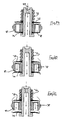
- Figs. 8-9 illustrate a flow control valve having the characteristics of the valve of Figs. 6 and 7 , and with secondary pressure relief in both directions of flow.
- the sleeve 61 floats at a position of mid-travel in the body 62 by virtue of stacks of Belleville spring washers 63, 64 on either side thereof. As illustrated in Fig. 8 , the spring stacks exert a closing force on the spring discs 65, 66 so that the through passages 67 are normally closed in both directions. A throat 68 is provided in the sleeve 61, as before.
- a further increased in pressure causes the sleeve to move, thus permitting unseating of the respective spring disc 66, and a second stage of pressure relief, as illustrated in Fig. 10 .
- two-stage pressure relief is also provided, but the relief characteristic may be different, as demonstrated by the different number of spring washers in the spring stacks 65, 64. It will be understood that coil springs may also be used in the embodiment of Figs. 8-10 .
- the bore of the hydraulic duct may be around 36 mm, and the spring disc may be of spring steel, about 0.19 mm thick.
- FIG. 11 A typical operating characteristic for the valve of the Figs. 8-10 illustrated in Fig. 11 .
- the normally closed mid-condition of the valve is represented by chain-dot line 71.
- hydraulic flow is solely via the valve throat 68.
- the volume of fluid is greater and accordingly the first stage of relief is provided via deformation of the respective spring disc 65, 66.
- the second stage of relief is required via unseating to the respective spring disc 65, 66.
- the characteristics for bump (compression) and rebound may be individually tuned so that the response on either side of the mid-condition may be different.
- Fig. 12 illustrates a flow control valve insert in accordance with the invention, and substantially corresponding to the single acting embodiments of Figs. 6 and 7 .
- the body 71, coil spring 72, spring discs 73, 74, head 75 and abutment 76 can be clearly seen.
- FIG. 13 shows one embodiment of through passages 77, 78 which are different in the bounce and rebound directions.
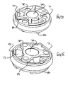
- Figs. 14 and 15 show perspective views of the valve body of Fig. 12 on an enlarged scale.
- the central bore 79 is defined for the moving sleeve, and the through passages 77, 78 are defined by respective upstanding walls 80, 81 which constitute a means of supporting the spring discs above the corresponding openings which correspond to the slots 24. Additional upstands 82 are provided on one side to support the corresponding spring disc.
- the valve body 71 may for example comprise an aluminium die casting.
- Fig. 16 shows low speed compression (bump) flow with hydraulic oil passing solely via restrictor 83.
- the spring disc 73 lifts at the edge to allow additional flow via the through passages 77.
- the build-up of pressure is sufficient to lift the spring disc 73 fully from the seat formed by wall 80 to allow a further increase in fluid flow.
- Rebound flow is illustrated in Figs. 19-21 , during which time the through passages 77 are blocked by the spring disc 73.
- both instances of high flow cause compression of the coil spring 72, and the second stage relief may thus be identical for both directions of fluid flow.
- an open through passage of a sleeve is depicted.
- this bypass passage may be provided in many other ways.
- the passage may be around the perimeter of the valve body, for example by providing a "loose" diametral fit or a notch in the circumferential wall of the valve body, or duct in which it is contained.
- a controlled bypass of a normally closed leaf spring may be provided, for example by means of one or more channels in the corresponding valve seat.
- Other alternatives will occur to a person skilled in the art of hydraulic valve design.
Abstract
Description
- The present invention relates to a control valve of a hydraulic duct, the valve being adapted to control hydraulic flow in both directions through the duct.
- Hydraulic systems rely upon flow of a hydraulic fluid, typically an oil or water based liquid, to achieve a desired effect. One example of such a system is a hydropneumatic suspension of a vehicle, in which road wheels are mounted on respective hydraulic actuators, and springing is provided by a hydropneumatic suspension module containing a springing medium, such as nitrogen gas. Suspension modules are typically in the form of a sphere having a diaphragm separating hydraulic fluid from a suspension gas under pressure. Working of the suspension causes movement of hydraulic fluid to and from the sphere. Such suspension systems are well known and need not be further described here.
- As the hydraulic fluid moves to and from the suspension module, some means of damping must be provided to reduce the amplitude of suspension movement. Orifices and spring loaded relief valves have been proposed to allow suspension characteristics to be tuned for optimized ride and handling of the vehicle. The characteristics for bump and rebound are usually different, so that typically the fluid flow path in the bump (upward) direction of a wheel is different from that of the rebound (downward) direction of a wheel.
- Some kinds of vehicle, particularly agricultural and construction vehicles, are designed to operate both on and off highway. The respective ranges of suspension movement are significantly different, so that a suspension optimized for on-highway use may be too hard for off-highway use. Conversely a suspension capable of accommodating wheel deflections in off-highway use may be uncomfortably soft in on-highway conditions. In either case the speed of travel of a vehicle may be severely limited if used on terrain for which the suspension is not optimized. A driver selectable alternative increases expense and complication, and is preferably avoided.
- It would be desirable to have a simplified bi-directional flow control valve with several integrated features to permit tuning thereof, particularly to accommodate ranges of suspension movement appropriate for both on-highway and off-highway vehicle use.
- According to the invention there is provided a flow control valve for a hydraulic conduit, said valve comprising a valve body having an open through passage defining a flow restriction, and an arcuate array of flow relief passages, each of said relief passages having at one side a closure comprising a leaf spring, and at least one said leaf spring being provided at each side of the valve body, wherein said valve includes a piston reciprocal in said body, said piston having end abutments to limit travel thereof, said piston being resiliently biased in one direction to permit said one end abutment to seat a corresponding leaf spring at one side of said body, and being movable under increasing hydraulic pressure to unseat said corresponding leaf spring, thereby to open a respective relief passage.
- Such a bi-directional valve is substantially symmetrical and relatively straightforward to manufacture whilst being tunable for both bump and rebound.
- The open through passage may be provided in said piston, for example as an axial opening of a substantial annular piston.
- The array of relief passage may be circular and equispaced. The leaf springs may be circular and annular, and the lip thereof may lift under pressure to provide a first relief opening. A second relief opening is provided by sliding motion of the piston within the body.
- In one embodiment a double acting relief valve has two-stage relief available for both directions of hydraulic flow (bump and rebound), both stages on each side being independently tunable.
- Such a valve provides damping and flow relief suitable for on-highway travel, yet can provide for additional suspension travel in off-highway travel whilst maintaining an acceptable ride and handling characteristic at speed.
- Features of the invention will be apparent from the appended claims.
- Other features of the invention will be apparent from the following description of a preferred embodiment illustrated by way of example only in the accompanying drawings in which:
-
Fig. 1 illustrates a hydropneumatic wheel suspension of a vehicle. -
Fig. 2 illustrates in plan a circular valve element for use in the present invention. -
Fig. 3 is a vertical section (as viewed) through the centre of the element ofFig. 2 . -
Fig. 4 is a horizontal section (as viewed) through the centre of the element ofFig. 2 . -
Fig. 5 is a partial section showing one mode of operation of the valve element ofFigs. 2-4 . -
Fig. 6 is a transverse section through a first embodiment according to the invention. -
Fig. 7 is a transverse section through a second embodiment according to the invention. -
Fig. 8 is a transverse section through a third embodiment according to the invention in a first stage of operation. -
Fig. 9 is a transverse section through a fourth embodiment according to the invention in a second stage of operation. -
Fig. 10 is a transverse section though a fifth embodiment according to the invention in a third stage of operation. -
Fig. 11 shows the graphical relationship between operating speed and internal pressure drop in an embodiment of the invention, for both bounce and rebound. -
Fig. 12 shows inside elevation a sixth embodiment of the invention. -
Fig. 13 is a diametral cross-section on line '13-13' ofFig. 12 . -
Figs. 14 and 15 show perspective views of the valve body ofFig. 12 from above and below. -
Figs. 16-21 show schematically the stages of operation of the valve ofFig. 12 , in both bump and rebound. - With reference to
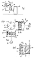
Fig. 1 , a vehicle 11 has awheel 12 connected thereto by apivotable suspension arm 13. Ahydraulic strut 14 permits suspension movement of the wheel and is coupled via a hydraulic line 15 to asuspension sphere 16 having aninternal diaphragm 17 confining pressurizedgas 18 on one side thereof. A fluid restrictor 19 provides damping of the movement of hydraulic fluid as the suspension is worked.Fig. 1 illustrates astrut 14 by way of example, but any suitable actuator or motor may be used. - Although an independent suspension of one wheel is illustrated in
figure 1 , this kind of suspension is also fitted to beam axle vehicles. - One element of the invention for inclusion in a practical valve embodiment is illustrated in
Figs. 2-4 . Acylindrical body 21 fits closely within ahydraulic duct 22, and has four equispaced throughapertures 23. The opposite end faces of thebody 21 are planar, and at each side two of the apertures open to the outer periphery viarespective slots 24. - The opposite end faces each have a
respective spring disc apertures 23, but less than the internal diameter of theduct 22, so that a fluid flow passage is formed from either side as illustrated byarrows - The hydraulic duct is in use part of the hydraulic line 15, and is connected at one side to the
suspension sphere 16, and at the other side to thestrut 14. - In use fluid flow passing through the
slots 24 enters two of the apertures, depending upon the direction of flow; the other two apertures in the same flow direction are blocked by the respective spring disc. At a predetermined pressure, the respective spring disc lifts in the manner of a leaf spring to uncover the apertures on the downstream side, thus allowing the passage of hydraulic fluid (Fig. 5 ). On the upstream side fluid pressure holds the other spring disc against thebody 21. Flow in the opposite direction is controlled in the same manner, and is via the other two apertures. - The valve element of
Fig. 2 is simple, and permits considerable tuning of the opening and flow characteristics, for example by altering the number and/or the diameter and/or the shape of theapertures 23, the size of theslots 24, the outside diameter of thediscs discs - A flow control valve in accordance with one embodiment of the invention is illustrated in
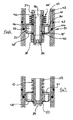
Fig. 6 , and incorporates anelement 31 of the kind illustrated inFigs. 2-5 . Theelement 31 consists of abody 32 having a circular array of throughpassages 33, some of which allow flow downwards (as illustrated) and some of which allow flow upwards (as illustrated). Oneslot 34 is shown inFig. 6 , and others are out of the plane of the section illustrated. - The
body 32 is retained in astepped duct 41 by a close-fitting insert 42, andsealing rings 43, 44 are provided in respective grooves to prevent leakage of hydraulic fluid. The duct may form part of an independent hydraulic device, or may be incorporated within thestrut 14 orsuspension sphere 17 in use. - The body is provided with a central through bore 35 within which is located a sliding piston in the form of a
sleeve 36 having an enlarged head 37. Axial movement of the sleeve is restricted by anabutment 38 provided on the opposite end to the head 37. The through passage of the sleeve contains a throat orrestrictor 39 which is open but constitutes a restriction to flow of hydraulic fluid therethrough. The restrictor may be quite small, and in one embodiment is a side of the order of 1-2 mm in diameter. - The
sleeve 36 is biased upwardly (as viewed) by a stack ofBelleville spring washers 45 between thebody 32 and head 37, and placed back to back so as to exert a pre-load;suitable thrust washers 46 are included, and it will be understood that in consequence thespring discs passages 33. - In practice the
sleeve 36 may comprise a screw-threaded bolt having an internal hex head 37 and a self-locking nut asabutment 38. The nut may be used to adjust the pre-load exerted by the stack ofspring washers 45. - Operation of the flow control valve of
Fig. 6 is as follows. Free flow of hydraulic fluid is permitted in either direction via thethroat 39, which constitutes a flow restriction. The area of the throat is tuned (for example by drilling a hole of appropriate diameter) to damp the flow of fluid, and thus cause suspension oscillation to diminish. Such a restrictive throat is suitable for optimizing on-road suspension characteristics. - It is typically desirable to permit greater flow in one direction than the other, for example to give different bounce and rebound characteristics to the invention. Thus, as illustrated, if hydraulic pressure increases at the upper side, by virtue of the flow restriction imposed at the
throat 39, such pressure will act via the slot(s) 34 on thespring disc 48, and cause it to bend downwardly (as viewed) so as to open the associated through passage. A further increase in hydraulic pressure causes thesleeve 36 to act as a piston and compress thespring stack 45 to move theabutment 38 downwardly. As a result thespring disc 48 disengages thebody 32, and allows additional flow of hydraulic fluid to the downstream side via the respective through passage(s) 33. As fluid pressure on the upper side falls, thesleeve 36 will return upwardly to re-seat thespring disc 48 on thebody 32, and allow the throughpassages 33 to be closed. - This arrangement provides a two-stage relief valve which opens at a predetermined hydraulic pressures, and may provide for the greater suspension movements which are characteristic of off-road travel. It will be understood that the Belleville washers may be arranged in the same or in different directions so as to alter the spring characteristic.
- In this embodiment, a second stage relief valve is also provided in the reverse direction, i.e. upon build-up of hydraulic pressure on the lower side, as viewed. First stage pressure relief is provided by bending of the
upper spring disc 47, and second stage relief by movement of thespring disc 47 upwardly against the effect of thespring stack 45. - The arrangement of
Fig. 7 is substantially identical to that ofFig. 6 save that thespring stack 45 is replaced by acoil spring 51, and that adjustability provided by the threadedabutment 38 is removed. Thesleeve 52 is unthreaded and the lower abutment is provided by a circlip orspring ring 53, which gives a fixed pre-load to thecoil spring 51. - Operation of the embodiment of
Fig. 7 is identical to that ofFig. 6 , but the different spring characteristics of thecoil spring 51 andspring stack 45 allow a different relationship between hydraulic pressure and travel of the sleeve. - The flow control valve may be inserted in the hydraulic line 15 in either direction according to the requirements of use. In use the relief provided by movement of the
sleeves 37, 52 is typically sequential to relief provided by bending of thespring discs -
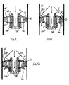
Figs. 8-9 illustrate a flow control valve having the characteristics of the valve ofFigs. 6 and 7 , and with secondary pressure relief in both directions of flow. - The sleeve 61 floats at a position of mid-travel in the
body 62 by virtue of stacks ofBelleville spring washers Fig. 8 , the spring stacks exert a closing force on thespring discs passages 67 are normally closed in both directions. A throat 68 is provided in the sleeve 61, as before. - In use flow from one side of the valve to the other is initially damped by the throat 68 (flow from above illustrated in
Fig. 8 ). As the volume of hydraulic fluid to be moved through the valve increases, pressure builds up and thespring disc 66 bends to allow a first stage of pressure relief, as illustrated inFig. 9 . - A further increased in pressure causes the sleeve to move, thus permitting unseating of the
respective spring disc 66, and a second stage of pressure relief, as illustrated inFig. 10 . - In the opposite direction, two-stage pressure relief is also provided, but the relief characteristic may be different, as demonstrated by the different number of spring washers in the spring stacks 65, 64. It will be understood that coil springs may also be used in the embodiment of
Figs. 8-10 . - In the embodiments of
Figs. 8-10 , the bore of the hydraulic duct may be around 36 mm, and the spring disc may be of spring steel, about 0.19 mm thick. - A typical operating characteristic for the valve of the
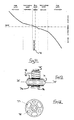
Figs. 8-10 illustrated inFig. 11 . - The normally closed mid-condition of the valve is represented by chain-
dot line 71. - For slow speed movement of the suspension in either direction, represented by a relatively small pressure drop, hydraulic flow is solely via the valve throat 68. At intermediate speeds, the volume of fluid is greater and accordingly the first stage of relief is provided via deformation of the
respective spring disc respective spring disc - The characteristics for bump (compression) and rebound may be individually tuned so that the response on either side of the mid-condition may be different.
-
Fig. 12 illustrates a flow control valve insert in accordance with the invention, and substantially corresponding to the single acting embodiments ofFigs. 6 and 7 . Thebody 71,coil spring 72,spring discs - The cross-section of
Fig. 13 shows one embodiment of throughpassages -
Figs. 14 and 15 show perspective views of the valve body ofFig. 12 on an enlarged scale. Thecentral bore 79 is defined for the moving sleeve, and the throughpassages upstanding walls slots 24.Additional upstands 82 are provided on one side to support the corresponding spring disc. Thevalve body 71 may for example comprise an aluminium die casting. - Stages of operation of the flow control valve of
Figs. 12-15 are illustrated inFigs. 16-21 . -
Fig. 16 shows low speed compression (bump) flow with hydraulic oil passing solely via restrictor 83. At medium speed, thespring disc 73 lifts at the edge to allow additional flow via the throughpassages 77. At high speed the build-up of pressure is sufficient to lift thespring disc 73 fully from the seat formed bywall 80 to allow a further increase in fluid flow. - During compression flow the
spring disc 74 remains seated, thus blocking the corresponding throughpassages 78. - Rebound flow is illustrated in
Figs. 19-21 , during which time the throughpassages 77 are blocked by thespring disc 73. - At low rebound speed flow is solely via the throat 83. At medium speed (
Fig. 20 ), thespring disc 74 lifts at the edge to allow additional flow through thepassages 78. At high speed (Fig. 21 ), the build-up of hydraulic pressure is sufficient to liftspring disc 74 fully from the seat formed bywall 81, to allow a further increase in fluid flow. - It will be appreciated that both instances of high flow cause compression of the
coil spring 72, and the second stage relief may thus be identical for both directions of fluid flow. - In the described embodiments of
figures 6 to 9 and16 to 21 , an open through passage of a sleeve is depicted. However, this bypass passage may be provided in many other ways. For example, the passage may be around the perimeter of the valve body, for example by providing a "loose" diametral fit or a notch in the circumferential wall of the valve body, or duct in which it is contained. In another alternative a controlled bypass of a normally closed leaf spring may be provided, for example by means of one or more channels in the corresponding valve seat. Other alternatives will occur to a person skilled in the art of hydraulic valve design.
Claims (16)
- A flow control valve for a hydraulic conduit, said valve comprising a valve body having an open through passage defining a flow restriction, and an arcuate array of flow relief passages, each of said relief passages having at one side a closure comprising a leaf spring, and at least one said leaf spring being provided at each side of the valve body, wherein said valve includes a piston reciprocal in said body, said piston having end abutments to limit travel thereof, said piston being resiliently biased in one direction to permit said one end abutment to seat a corresponding leaf spring at one side of said body, and being movable under increasing hydraulic pressure to unseat said corresponding leaf spring, thereby to open a respective relief passage.
- A valve according to claim1 wherein said array of relief passages is circular.
- A valve according to claim 1 or claim 2 wherein one end abutment of said piston is axially adjustable.
- A valve according to claim 3 wherein said one end abutment comprises a nut screw-threaded on the corresponding end of said piston.
- A valve according to any preceding claim wherein a circular leaf spring is provided on each side of the valve body, the periphery of said leaf spring being deformable under pressure to open one or more respective relief passages.
- A valve according to claim 5 wherein resilient bias for said piston is provided by an annular spring acting between an end abutment and said body.
- A valve according to claim 6 wherein said annular spring is a coil spring or wherein said annular spring is a stack of Belleville spring washers, preferably said stack comprises a plurality of spring washers arranged back to back.
- A valve according to any of claims 6 to 7 wherein one of said circular leaf springs is directly seated by said annular spring.
- A valve according to any of claims 6 to 8 wherein each said flow relief passage includes at one end a radially outwardly extending channel.
- A valve according to any of claims 6 to 9 wherein a resilient bias for said piston is provided on both sides thereof by a respective annular spring acting between a respective end abutment and said body.
- A valve according to claim 10 wherein the respective annular springs have a different pre-load and/or a differential rate.
- A valve according to any of claims 10 or 11 wherein said annular springs include a coil spring or wherein said annular springs comprise stacks of Belleville spring washers, preferably said stack comprises a plurality of spring washers arranged back to back.
- A valve according to any of claims 10 to 12 wherein said annular springs directly seat a respective circular leaf spring.
- A valve according to any preceding claim wherein said open through passage is provided in said piston.
- A flow control valve assembly comprising a through duct and a fixed therein flow control valve according to any of claims 1 to 14.
- A vehicle having a hydropneumatic suspension comprising a hydraulic line between a wheel suspension actuator and a hydropneumatic spring chamber, and a flow control valve assembly according to claim 15.
Applications Claiming Priority (1)
| Application Number | Priority Date | Filing Date | Title |
|---|---|---|---|
| GB1400611.8A GB2522191B (en) | 2014-01-15 | 2014-01-15 | Bi-directional hydraulic flow control valve |
Publications (3)
| Publication Number | Publication Date |
|---|---|
| EP2899425A1 true EP2899425A1 (en) | 2015-07-29 |
| EP2899425B1 EP2899425B1 (en) | 2018-01-31 |
| EP2899425B8 EP2899425B8 (en) | 2021-10-27 |
Family
ID=50238952
Family Applications (1)
| Application Number | Title | Priority Date | Filing Date |
|---|---|---|---|
| EP14196448.6A Active EP2899425B8 (en) | 2014-01-15 | 2014-12-05 | B-directional hydraulic flow control valve |
Country Status (5)
| Country | Link |
|---|---|
| US (1) | US9347572B2 (en) |
| EP (1) | EP2899425B8 (en) |
| AU (1) | AU2015200178B2 (en) |
| CA (1) | CA2875855A1 (en) |
| GB (1) | GB2522191B (en) |
Families Citing this family (3)
| Publication number | Priority date | Publication date | Assignee | Title |
|---|---|---|---|---|
| CN107143603B (en) * | 2017-06-28 | 2019-01-25 | 中车青岛四方车辆研究所有限公司 | Valve component, piston unit and oil-pressure damper |
| CN107630964B (en) * | 2017-09-20 | 2023-08-11 | 肇庆市维德亚科技有限公司 | Hydraulic damper |
| CN112483691B (en) * | 2020-10-27 | 2022-07-05 | 北京宇航系统工程研究所 | Anti-vibration disc spring one-way valve |
Citations (4)
| Publication number | Priority date | Publication date | Assignee | Title |
|---|---|---|---|---|
| DE4024789C1 (en) * | 1990-08-04 | 1991-12-12 | Boge Ag, 5208 Eitorf, De | Piston for hydraulic, telescopic shock absorber - has through duct outlets interconnected on each piston front side |
| WO2001063141A1 (en) * | 2000-02-23 | 2001-08-30 | Peugeot Citroen Automobiles S.A. | Device forming asymmetric damper for a motor vehicle suspension |
| US20070034466A1 (en) * | 2005-08-15 | 2007-02-15 | Tenneco Automotive Operating Company, Inc. | Asymmetrical intake damper valve |
| WO2007022921A1 (en) * | 2005-08-24 | 2007-03-01 | Zf Friedrichshafen Ag | Vibration damper |
Family Cites Families (7)
| Publication number | Priority date | Publication date | Assignee | Title |
|---|---|---|---|---|
| US3718159A (en) * | 1971-01-20 | 1973-02-27 | Hydraulic Industries | Control valve |
| US6371264B1 (en) * | 1999-06-09 | 2002-04-16 | Denso Corporation | Fulcrum blow off valve for use in a shock absorber |
| US6464053B1 (en) * | 1999-07-26 | 2002-10-15 | Tenneco Automotive Operating Company, Inc. | Single piece piston |
| US7070029B2 (en) * | 2003-09-15 | 2006-07-04 | Tenneco Automotive Operating Company Inc. | Monotube piston valving system with selective bleed |
| US6899207B2 (en) * | 2003-09-29 | 2005-05-31 | Tenneco Automotive Operating Company Inc. | Extra support area for valve disc |
| DE102006028745A1 (en) * | 2005-06-21 | 2007-05-03 | Tenneco Automotive Operating Company Inc., Lake Forest | Four-piece piston |
| JP5812650B2 (en) | 2011-03-31 | 2015-11-17 | 日立オートモティブシステムズ株式会社 | Damping force adjustable shock absorber |
-
2014
- 2014-01-15 GB GB1400611.8A patent/GB2522191B/en active Active
- 2014-12-05 EP EP14196448.6A patent/EP2899425B8/en active Active
- 2014-12-29 CA CA2875855A patent/CA2875855A1/en not_active Abandoned
-
2015
- 2015-01-14 US US14/597,122 patent/US9347572B2/en active Active
- 2015-01-15 AU AU2015200178A patent/AU2015200178B2/en active Active
Patent Citations (4)
| Publication number | Priority date | Publication date | Assignee | Title |
|---|---|---|---|---|
| DE4024789C1 (en) * | 1990-08-04 | 1991-12-12 | Boge Ag, 5208 Eitorf, De | Piston for hydraulic, telescopic shock absorber - has through duct outlets interconnected on each piston front side |
| WO2001063141A1 (en) * | 2000-02-23 | 2001-08-30 | Peugeot Citroen Automobiles S.A. | Device forming asymmetric damper for a motor vehicle suspension |
| US20070034466A1 (en) * | 2005-08-15 | 2007-02-15 | Tenneco Automotive Operating Company, Inc. | Asymmetrical intake damper valve |
| WO2007022921A1 (en) * | 2005-08-24 | 2007-03-01 | Zf Friedrichshafen Ag | Vibration damper |
Also Published As
| Publication number | Publication date |
|---|---|
| AU2015200178B2 (en) | 2019-01-31 |
| CA2875855A1 (en) | 2015-07-15 |
| US9347572B2 (en) | 2016-05-24 |
| EP2899425B8 (en) | 2021-10-27 |
| AU2015200178A1 (en) | 2015-07-30 |
| GB2522191A (en) | 2015-07-22 |
| GB2522191B (en) | 2020-04-29 |
| US20150198213A1 (en) | 2015-07-16 |
| GB201400611D0 (en) | 2014-03-05 |
| EP2899425B1 (en) | 2018-01-31 |
Similar Documents
| Publication | Publication Date | Title |
|---|---|---|
| US8800729B2 (en) | Damping force control type shock absorber | |
| CN107208726B (en) | Secondary damper assembly for damper | |
| US5738190A (en) | Flexing disc-blow off assembly for use in a shock absorber | |
| US4972929A (en) | Bidirectional dual disc valve assembly | |
| KR102121484B1 (en) | Piston assembly with open bleed | |
| CN103256335B (en) | Nested check high speed valve | |
| US6119829A (en) | Hydraulic shock absorber with variable damping resistance | |
| JP5758119B2 (en) | Shock absorber | |
| US20180216690A1 (en) | Shock absorber | |
| CN107091294B (en) | Shock absorber with check disc for orifice passage | |
| JPH05508001A (en) | Adjustable hydraulic valve for shock absorber | |
| US6450304B1 (en) | Piston and rod assembly for air-actuated variable damping | |
| US9587703B2 (en) | Variable radius spring disc for vehicle shock absorber | |
| US10663027B2 (en) | Damper with valve preload limiter | |
| US5921360A (en) | Digressive damper valve | |
| US9347572B2 (en) | Bi-directional hydraulic flow control valve | |
| WO2007029861A1 (en) | Damping force generating mechanism of hydraulic shock absorber | |
| CN109983249B (en) | Frequency dependent damper | |
| EP3012483B1 (en) | Valve arrangement with improved failsafe operation | |
| KR101465677B1 (en) | Support washer for shock absorber valve with blow-off tunability | |
| CN112360913B (en) | Hydraulic damper and piston for a hydraulic damper assembly | |
| US11236799B2 (en) | Valve assembly for a damper | |
| JP6626631B2 (en) | Shock absorber | |
| JP2022129195A (en) | Damping valve and buffer |
Legal Events
| Date | Code | Title | Description |
|---|---|---|---|
| PUAI | Public reference made under article 153(3) epc to a published international application that has entered the european phase |
Free format text: ORIGINAL CODE: 0009012 |
|
| 17P | Request for examination filed |
Effective date: 20141205 |
|
| AK | Designated contracting states |
Kind code of ref document: A1 Designated state(s): AL AT BE BG CH CY CZ DE DK EE ES FI FR GB GR HR HU IE IS IT LI LT LU LV MC MK MT NL NO PL PT RO RS SE SI SK SM TR |
|
| AX | Request for extension of the european patent |
Extension state: BA ME |
|
| 17P | Request for examination filed |
Effective date: 20151203 |
|
| RBV | Designated contracting states (corrected) |
Designated state(s): AL AT BE BG CH CY CZ DE DK EE ES FI FR GB GR HR HU IE IS IT LI LT LU LV MC MK MT NL NO PL PT RO RS SE SI SK SM TR |
|
| GRAP | Despatch of communication of intention to grant a patent |
Free format text: ORIGINAL CODE: EPIDOSNIGR1 |
|
| STAA | Information on the status of an ep patent application or granted ep patent |
Free format text: STATUS: GRANT OF PATENT IS INTENDED |
|
| INTG | Intention to grant announced |
Effective date: 20170703 |
|
| GRAS | Grant fee paid |
Free format text: ORIGINAL CODE: EPIDOSNIGR3 |
|
| GRAA | (expected) grant |
Free format text: ORIGINAL CODE: 0009210 |
|
| STAA | Information on the status of an ep patent application or granted ep patent |
Free format text: STATUS: THE PATENT HAS BEEN GRANTED |
|
| AK | Designated contracting states |
Kind code of ref document: B1 Designated state(s): AL AT BE BG CH CY CZ DE DK EE ES FI FR GB GR HR HU IE IS IT LI LT LU LV MC MK MT NL NO PL PT RO RS SE SI SK SM TR |
|
| REG | Reference to a national code |
Ref country code: GB Ref legal event code: FG4D Ref country code: CH Ref legal event code: EP |
|
| REG | Reference to a national code |
Ref country code: AT Ref legal event code: REF Ref document number: 967681 Country of ref document: AT Kind code of ref document: T Effective date: 20180215 |
|
| REG | Reference to a national code |
Ref country code: IE Ref legal event code: FG4D |
|
| REG | Reference to a national code |
Ref country code: DE Ref legal event code: R096 Ref document number: 602014020325 Country of ref document: DE |
|
| REG | Reference to a national code |
Ref country code: NL Ref legal event code: MP Effective date: 20180131 |
|
| REG | Reference to a national code |
Ref country code: LT Ref legal event code: MG4D |
|
| REG | Reference to a national code |
Ref country code: AT Ref legal event code: MK05 Ref document number: 967681 Country of ref document: AT Kind code of ref document: T Effective date: 20180131 |
|
| PG25 | Lapsed in a contracting state [announced via postgrant information from national office to epo] |
Ref country code: FI Free format text: LAPSE BECAUSE OF FAILURE TO SUBMIT A TRANSLATION OF THE DESCRIPTION OR TO PAY THE FEE WITHIN THE PRESCRIBED TIME-LIMIT Effective date: 20180131 Ref country code: NO Free format text: LAPSE BECAUSE OF FAILURE TO SUBMIT A TRANSLATION OF THE DESCRIPTION OR TO PAY THE FEE WITHIN THE PRESCRIBED TIME-LIMIT Effective date: 20180430 Ref country code: HR Free format text: LAPSE BECAUSE OF FAILURE TO SUBMIT A TRANSLATION OF THE DESCRIPTION OR TO PAY THE FEE WITHIN THE PRESCRIBED TIME-LIMIT Effective date: 20180131 Ref country code: ES Free format text: LAPSE BECAUSE OF FAILURE TO SUBMIT A TRANSLATION OF THE DESCRIPTION OR TO PAY THE FEE WITHIN THE PRESCRIBED TIME-LIMIT Effective date: 20180131 Ref country code: NL Free format text: LAPSE BECAUSE OF FAILURE TO SUBMIT A TRANSLATION OF THE DESCRIPTION OR TO PAY THE FEE WITHIN THE PRESCRIBED TIME-LIMIT Effective date: 20180131 Ref country code: LT Free format text: LAPSE BECAUSE OF FAILURE TO SUBMIT A TRANSLATION OF THE DESCRIPTION OR TO PAY THE FEE WITHIN THE PRESCRIBED TIME-LIMIT Effective date: 20180131 |
|
| PG25 | Lapsed in a contracting state [announced via postgrant information from national office to epo] |
Ref country code: AT Free format text: LAPSE BECAUSE OF FAILURE TO SUBMIT A TRANSLATION OF THE DESCRIPTION OR TO PAY THE FEE WITHIN THE PRESCRIBED TIME-LIMIT Effective date: 20180131 Ref country code: IS Free format text: LAPSE BECAUSE OF FAILURE TO SUBMIT A TRANSLATION OF THE DESCRIPTION OR TO PAY THE FEE WITHIN THE PRESCRIBED TIME-LIMIT Effective date: 20180531 Ref country code: BG Free format text: LAPSE BECAUSE OF FAILURE TO SUBMIT A TRANSLATION OF THE DESCRIPTION OR TO PAY THE FEE WITHIN THE PRESCRIBED TIME-LIMIT Effective date: 20180430 Ref country code: PL Free format text: LAPSE BECAUSE OF FAILURE TO SUBMIT A TRANSLATION OF THE DESCRIPTION OR TO PAY THE FEE WITHIN THE PRESCRIBED TIME-LIMIT Effective date: 20180131 Ref country code: SE Free format text: LAPSE BECAUSE OF FAILURE TO SUBMIT A TRANSLATION OF THE DESCRIPTION OR TO PAY THE FEE WITHIN THE PRESCRIBED TIME-LIMIT Effective date: 20180131 Ref country code: GR Free format text: LAPSE BECAUSE OF FAILURE TO SUBMIT A TRANSLATION OF THE DESCRIPTION OR TO PAY THE FEE WITHIN THE PRESCRIBED TIME-LIMIT Effective date: 20180501 Ref country code: LV Free format text: LAPSE BECAUSE OF FAILURE TO SUBMIT A TRANSLATION OF THE DESCRIPTION OR TO PAY THE FEE WITHIN THE PRESCRIBED TIME-LIMIT Effective date: 20180131 Ref country code: RS Free format text: LAPSE BECAUSE OF FAILURE TO SUBMIT A TRANSLATION OF THE DESCRIPTION OR TO PAY THE FEE WITHIN THE PRESCRIBED TIME-LIMIT Effective date: 20180131 |
|
| PG25 | Lapsed in a contracting state [announced via postgrant information from national office to epo] |
Ref country code: RO Free format text: LAPSE BECAUSE OF FAILURE TO SUBMIT A TRANSLATION OF THE DESCRIPTION OR TO PAY THE FEE WITHIN THE PRESCRIBED TIME-LIMIT Effective date: 20180131 Ref country code: EE Free format text: LAPSE BECAUSE OF FAILURE TO SUBMIT A TRANSLATION OF THE DESCRIPTION OR TO PAY THE FEE WITHIN THE PRESCRIBED TIME-LIMIT Effective date: 20180131 Ref country code: IT Free format text: LAPSE BECAUSE OF FAILURE TO SUBMIT A TRANSLATION OF THE DESCRIPTION OR TO PAY THE FEE WITHIN THE PRESCRIBED TIME-LIMIT Effective date: 20180131 Ref country code: AL Free format text: LAPSE BECAUSE OF FAILURE TO SUBMIT A TRANSLATION OF THE DESCRIPTION OR TO PAY THE FEE WITHIN THE PRESCRIBED TIME-LIMIT Effective date: 20180131 |
|
| REG | Reference to a national code |
Ref country code: DE Ref legal event code: R097 Ref document number: 602014020325 Country of ref document: DE |
|
| PG25 | Lapsed in a contracting state [announced via postgrant information from national office to epo] |
Ref country code: DK Free format text: LAPSE BECAUSE OF FAILURE TO SUBMIT A TRANSLATION OF THE DESCRIPTION OR TO PAY THE FEE WITHIN THE PRESCRIBED TIME-LIMIT Effective date: 20180131 Ref country code: CZ Free format text: LAPSE BECAUSE OF FAILURE TO SUBMIT A TRANSLATION OF THE DESCRIPTION OR TO PAY THE FEE WITHIN THE PRESCRIBED TIME-LIMIT Effective date: 20180131 Ref country code: SM Free format text: LAPSE BECAUSE OF FAILURE TO SUBMIT A TRANSLATION OF THE DESCRIPTION OR TO PAY THE FEE WITHIN THE PRESCRIBED TIME-LIMIT Effective date: 20180131 Ref country code: SK Free format text: LAPSE BECAUSE OF FAILURE TO SUBMIT A TRANSLATION OF THE DESCRIPTION OR TO PAY THE FEE WITHIN THE PRESCRIBED TIME-LIMIT Effective date: 20180131 |
|
| PLBE | No opposition filed within time limit |
Free format text: ORIGINAL CODE: 0009261 |
|
| STAA | Information on the status of an ep patent application or granted ep patent |
Free format text: STATUS: NO OPPOSITION FILED WITHIN TIME LIMIT |
|
| 26N | No opposition filed |
Effective date: 20181102 |
|
| PG25 | Lapsed in a contracting state [announced via postgrant information from national office to epo] |
Ref country code: SI Free format text: LAPSE BECAUSE OF FAILURE TO SUBMIT A TRANSLATION OF THE DESCRIPTION OR TO PAY THE FEE WITHIN THE PRESCRIBED TIME-LIMIT Effective date: 20180131 |
|
| REG | Reference to a national code |
Ref country code: CH Ref legal event code: PL |
|
| PG25 | Lapsed in a contracting state [announced via postgrant information from national office to epo] |
Ref country code: MC Free format text: LAPSE BECAUSE OF FAILURE TO SUBMIT A TRANSLATION OF THE DESCRIPTION OR TO PAY THE FEE WITHIN THE PRESCRIBED TIME-LIMIT Effective date: 20180131 Ref country code: LU Free format text: LAPSE BECAUSE OF NON-PAYMENT OF DUE FEES Effective date: 20181205 |
|
| REG | Reference to a national code |
Ref country code: IE Ref legal event code: MM4A |
|
| REG | Reference to a national code |
Ref country code: BE Ref legal event code: MM Effective date: 20181231 |
|
| PG25 | Lapsed in a contracting state [announced via postgrant information from national office to epo] |
Ref country code: IE Free format text: LAPSE BECAUSE OF NON-PAYMENT OF DUE FEES Effective date: 20181205 Ref country code: FR Free format text: LAPSE BECAUSE OF NON-PAYMENT OF DUE FEES Effective date: 20181231 |
|
| PG25 | Lapsed in a contracting state [announced via postgrant information from national office to epo] |
Ref country code: BE Free format text: LAPSE BECAUSE OF NON-PAYMENT OF DUE FEES Effective date: 20181231 |
|
| PG25 | Lapsed in a contracting state [announced via postgrant information from national office to epo] |
Ref country code: LI Free format text: LAPSE BECAUSE OF NON-PAYMENT OF DUE FEES Effective date: 20181231 Ref country code: CH Free format text: LAPSE BECAUSE OF NON-PAYMENT OF DUE FEES Effective date: 20181231 |
|
| PG25 | Lapsed in a contracting state [announced via postgrant information from national office to epo] |
Ref country code: MT Free format text: LAPSE BECAUSE OF NON-PAYMENT OF DUE FEES Effective date: 20181205 |
|
| PG25 | Lapsed in a contracting state [announced via postgrant information from national office to epo] |
Ref country code: TR Free format text: LAPSE BECAUSE OF FAILURE TO SUBMIT A TRANSLATION OF THE DESCRIPTION OR TO PAY THE FEE WITHIN THE PRESCRIBED TIME-LIMIT Effective date: 20180131 |
|
| PG25 | Lapsed in a contracting state [announced via postgrant information from national office to epo] |
Ref country code: PT Free format text: LAPSE BECAUSE OF FAILURE TO SUBMIT A TRANSLATION OF THE DESCRIPTION OR TO PAY THE FEE WITHIN THE PRESCRIBED TIME-LIMIT Effective date: 20180131 |
|
| PG25 | Lapsed in a contracting state [announced via postgrant information from national office to epo] |
Ref country code: CY Free format text: LAPSE BECAUSE OF FAILURE TO SUBMIT A TRANSLATION OF THE DESCRIPTION OR TO PAY THE FEE WITHIN THE PRESCRIBED TIME-LIMIT Effective date: 20180131 Ref country code: HU Free format text: LAPSE BECAUSE OF FAILURE TO SUBMIT A TRANSLATION OF THE DESCRIPTION OR TO PAY THE FEE WITHIN THE PRESCRIBED TIME-LIMIT; INVALID AB INITIO Effective date: 20141205 Ref country code: MK Free format text: LAPSE BECAUSE OF NON-PAYMENT OF DUE FEES Effective date: 20180131 |
|
| GRAT | Correction requested after decision to grant or after decision to maintain patent in amended form |
Free format text: ORIGINAL CODE: EPIDOSNCDEC |
|
| PLAA | Information modified related to event that no opposition was filed |
Free format text: ORIGINAL CODE: 0009299DELT |
|
| PLBE | No opposition filed within time limit |
Free format text: ORIGINAL CODE: 0009261 |
|
| STAA | Information on the status of an ep patent application or granted ep patent |
Free format text: STATUS: NO OPPOSITION FILED WITHIN TIME LIMIT |
|
| REG | Reference to a national code |
Ref country code: CH Ref legal event code: PK Free format text: BERICHTIGUNG B8 |
|
| R26N | No opposition filed (corrected) |
Effective date: 20181102 |
|
| RAP4 | Party data changed (patent owner data changed or rights of a patent transferred) |
Owner name: J.C. BAMFORD EXCAVATORS LIMITED |
|
| P01 | Opt-out of the competence of the unified patent court (upc) registered |
Effective date: 20230522 |
|
| PGFP | Annual fee paid to national office [announced via postgrant information from national office to epo] |
Ref country code: GB Payment date: 20231214 Year of fee payment: 10 |
|
| PGFP | Annual fee paid to national office [announced via postgrant information from national office to epo] |
Ref country code: DE Payment date: 20231220 Year of fee payment: 10 |