EP2899381A1 - Prechamber gas engine - Google Patents
Prechamber gas engine Download PDFInfo
- Publication number
- EP2899381A1 EP2899381A1 EP13839517.3A EP13839517A EP2899381A1 EP 2899381 A1 EP2899381 A1 EP 2899381A1 EP 13839517 A EP13839517 A EP 13839517A EP 2899381 A1 EP2899381 A1 EP 2899381A1
- Authority
- EP
- European Patent Office
- Prior art keywords
- exhaust
- intake
- precombustion
- chamber
- nozzle hole
- Prior art date
- Legal status (The legal status is an assumption and is not a legal conclusion. Google has not performed a legal analysis and makes no representation as to the accuracy of the status listed.)
- Granted
Links
Images

Classifications
-
- F—MECHANICAL ENGINEERING; LIGHTING; HEATING; WEAPONS; BLASTING
- F02—COMBUSTION ENGINES; HOT-GAS OR COMBUSTION-PRODUCT ENGINE PLANTS
- F02B—INTERNAL-COMBUSTION PISTON ENGINES; COMBUSTION ENGINES IN GENERAL
- F02B19/00—Engines characterised by precombustion chambers
- F02B19/16—Chamber shapes or constructions not specific to sub-groups F02B19/02 - F02B19/10
- F02B19/18—Transfer passages between chamber and cylinder
-
- F—MECHANICAL ENGINEERING; LIGHTING; HEATING; WEAPONS; BLASTING
- F02—COMBUSTION ENGINES; HOT-GAS OR COMBUSTION-PRODUCT ENGINE PLANTS
- F02B—INTERNAL-COMBUSTION PISTON ENGINES; COMBUSTION ENGINES IN GENERAL
- F02B19/00—Engines characterised by precombustion chambers
- F02B19/12—Engines characterised by precombustion chambers with positive ignition
-
- F—MECHANICAL ENGINEERING; LIGHTING; HEATING; WEAPONS; BLASTING
- F02—COMBUSTION ENGINES; HOT-GAS OR COMBUSTION-PRODUCT ENGINE PLANTS
- F02D—CONTROLLING COMBUSTION ENGINES
- F02D19/00—Controlling engines characterised by their use of non-liquid fuels, pluralities of fuels, or non-fuel substances added to the combustible mixtures
- F02D19/02—Controlling engines characterised by their use of non-liquid fuels, pluralities of fuels, or non-fuel substances added to the combustible mixtures peculiar to engines working with gaseous fuels
-
- F—MECHANICAL ENGINEERING; LIGHTING; HEATING; WEAPONS; BLASTING
- F02—COMBUSTION ENGINES; HOT-GAS OR COMBUSTION-PRODUCT ENGINE PLANTS
- F02B—INTERNAL-COMBUSTION PISTON ENGINES; COMBUSTION ENGINES IN GENERAL
- F02B23/00—Other engines characterised by special shape or construction of combustion chambers to improve operation
- F02B23/08—Other engines characterised by special shape or construction of combustion chambers to improve operation with positive ignition
- F02B23/10—Other engines characterised by special shape or construction of combustion chambers to improve operation with positive ignition with separate admission of air and fuel into cylinder
- F02B23/101—Other engines characterised by special shape or construction of combustion chambers to improve operation with positive ignition with separate admission of air and fuel into cylinder the injector being placed on or close to the cylinder centre axis, e.g. with mixture formation using spray guided concepts
-
- Y—GENERAL TAGGING OF NEW TECHNOLOGICAL DEVELOPMENTS; GENERAL TAGGING OF CROSS-SECTIONAL TECHNOLOGIES SPANNING OVER SEVERAL SECTIONS OF THE IPC; TECHNICAL SUBJECTS COVERED BY FORMER USPC CROSS-REFERENCE ART COLLECTIONS [XRACs] AND DIGESTS
- Y02—TECHNOLOGIES OR APPLICATIONS FOR MITIGATION OR ADAPTATION AGAINST CLIMATE CHANGE
- Y02T—CLIMATE CHANGE MITIGATION TECHNOLOGIES RELATED TO TRANSPORTATION
- Y02T10/00—Road transport of goods or passengers
- Y02T10/10—Internal combustion engine [ICE] based vehicles
- Y02T10/12—Improving ICE efficiencies
-
- Y—GENERAL TAGGING OF NEW TECHNOLOGICAL DEVELOPMENTS; GENERAL TAGGING OF CROSS-SECTIONAL TECHNOLOGIES SPANNING OVER SEVERAL SECTIONS OF THE IPC; TECHNICAL SUBJECTS COVERED BY FORMER USPC CROSS-REFERENCE ART COLLECTIONS [XRACs] AND DIGESTS
- Y02—TECHNOLOGIES OR APPLICATIONS FOR MITIGATION OR ADAPTATION AGAINST CLIMATE CHANGE
- Y02T—CLIMATE CHANGE MITIGATION TECHNOLOGIES RELATED TO TRANSPORTATION
- Y02T10/00—Road transport of goods or passengers
- Y02T10/10—Internal combustion engine [ICE] based vehicles
- Y02T10/30—Use of alternative fuels, e.g. biofuels
Definitions
- the present disclosure relates to a precombustion-chamber gas engine that combusts mixed air in a main combustion chamber by injecting combustion flames into the main combustion chamber through a plurality of nozzle holes.
- the combustion flames are produced in a precombustion chamber disposed inside a precombustion chamber cap.
- FIG. 4 is a planar view of a cylinder head of a conventional precombustion-chamber gas engine as seen from below.
- This conventional precombustion-chamber gas engine 100 includes a precombustion chamber cap 108 disposed inside the cylinder head 104 at the center of the cylinder head 104, as illustrated in FIG. 4 .
- Two intake ports 113 and two exhaust ports 115 are opened around the precombustion chamber cap 108 of the cylinder head 104 so as to surround the precombustion chamber cap 108.
- two intake ports 113 are opened on the right side of the drawing, while two exhaust ports 115 are opened on the left side of the drawing.
- the above two intake ports 113 and two exhaust ports 115 are opened and closed by intake valves 112 and exhaust valve 114, respectively.
- the intake valves 112 open and close the intake ports 113 so that mixed air is supplied to the main combustion chamber 110 delimited between the cylinder head 104 and a top face of a non-illustrated piston.
- the exhaust valves 114 open and close the exhaust ports 115 so that exhaust gas in the main combustion chamber 110 is discharged.
- a precombustion chamber 120 is delimited inside the precombustion chamber cap 108.
- the precombustion chamber cap 108 includes a plurality of nozzle holes 116 that brings the precombustion chamber 120 into communication with the main combustion chamber 110.
- Six nozzle holes 116 are provided at equal intervals in the circumferential direction.
- the combustion flames "f" (hereinafter, referred to as torch jets) produced in the precombustion chamber 120 are injected into the main combustion chamber 110 through the nozzle holes 116, thereby combusting mixed air in the main combustion chamber 110.
- the arrows here of the torch jets "f” in FIG. 4 indicate the injecting direction and the strength of the penetration force of the torch jets "f".
- the torch jets "f” in the drawing indicate that they are injected evenly in terms of space and at the same penetration force inside the main combustion chamber 110.
- Patent Document 1 Japanese Unexamined Patent Application No. 2004-251213
- the inventors found that knocking tends to occur in a partial region of the main combustion chamber 110 in the conventional precombustion-chamber gas engine 100 with the above configuration. They conducted researches and the like to determine the cause. As a result, they found out that one cause is the uneven distribution of the flame propagation speed of the mixed air in the main combustion chamber ignited by the torch jets "f" due to the low temperature of the cylinder wall surface 102b in an intake-side region (region "B" in FIG. 4 ) where the intake ports 113 are provided compared to the temperature of the cylinder wall surface 102a in an exhaust-side region (region "A” in FIG. 4 ) where the exhaust ports 115 are provided.
- the flame propagation speed of the mixed air is low in the intake-side region (B), where the mixed air is ignited by torch jets "fb” injected from the nozzle holes 116b disposed so as to face the intake-side region (B), as compared to the flame propagation speed of the mixed air in the exhaust-side region, where the mixed air is ignited by torch jets "fa” injected from the nozzle holes 116a disposed so as to face the exhaust-side region (A), corresponding to the low temperature of the cylinder wall surface in the intake-side region (B) compared to the exhaust-side region (A).
- Patent Document 1 discloses an invention in which a combustion-chamber internal combustion engine includes a main combustion chamber and a precombustion chamber, and nozzle holes are arranged outwardly in the radial direction by a half length or more of the radius, so that combustion flames securely reach a top clearance part where non-combusted gas is likely to be produced. This invention of Patent Document 1, however, does not prevent knocking due to the temperature difference between an intake-side region (B) and an exhaust-side region (A).
- An object is to provide a precombustion-chamber gas engine where occurrence of knocking is restricted.
- At least one embodiment of the present invention provides a precombustion-chamber gas engine including: a cylinder; a cylinder head disposed on a top portion of the cylinder; a piston reciprocably disposed inside the cylinder, the piston delimiting a main combustion chamber with the cylinder head; a precombustion-chamber cap disposed inside the cylinder head at the center part of the cylinder head, the precombustion-chamber cap delimiting a precombustion chamber inside the precombustion-chamber cap and including a plurality of nozzle holes through which the precombustion chamber is in communication with the main combustion chamber; an intake valve for supplying mixed air to the main combustion chamber by opening and closing an intake port that opens on the cylinder head; and an exhaust valve for discharging exhaust gas in the main combustion chamber by opening and closing an exhaust port that opens on the cylinder head.
- a total nozzle-hole area of the at least one intake-side nozzle hole is larger than a total nozzle-hole area of the at least one exhaust-side nozzle hole.
- the total nozzle-hole area of the at least one intake-side nozzle hole is larger than the total nozzle-hole area of the at least one exhaust-side nozzle hole.
- the above configuration includes following two cases.
- the number of the intake-side nozzle holes is larger than that of the exhaust-side nozzle holes, so that the propagation area of the flame propagating from the torch jet injected from each intake-side nozzle holes is narrow (i.e., the propagation distance is short). Thus, a combustion flame reaches the cylinder wall surface in a shorter period of time.
- the number of the intake-side nozzle holes is the same as that of the exhaust-side nozzle holes.
- the total nozzle-hole area of the intake-side nozzle holes is larger than that of the exhaust-side nozzle holes, so that the penetration force of the torch jet injected from each intake-side nozzle hole is large and therefore the development distance of the torch jet is large, causing the propagation distance of the flames propagating from the torch jets to become short.
- a combustion flame reaches the cylinder wall surface in a shorter period of time.
- the number of the at least one intake-side nozzle hole is larger than the number of the at least one exhaust-side nozzle hole, and the at least one intake-side nozzle hole and the at least one exhaust-side nozzle hole each have an identical nozzle-hole area.
- the at least one intake-side nozzle hole and the at least one exhaust-side nozzle hole each have an identical nozzle-hole area as described above, forming the nozzle holes on the precombustion chamber cap is facilitated.
- the number of the at least one intake-side nozzle hole is equal to the number of the at least one exhaust-side nozzle hole, and each of the at least one intake-side nozzle hole has a nozzle hole area larger than a nozzle hole area of each of the at least one exhaust-side nozzle hole.
- the number of the at least one intake-side nozzle hole is equal to the number of the at least one exhaust-side nozzle hole, and each of the at least one intake-side nozzle hole has a nozzle hole area larger than a nozzle hole area of each of the at least one exhaust-side nozzle hole.
- the present invention it is possible to shorten the period of time in which the combustion flames injected from the intake-side nozzle holes reach the cylinder wall surface.
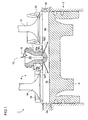
- FIG. 1 is a cross-sectional view of a precombustion-chamber gas engine according to one embodiment of the present invention.
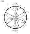
- FIG. 2 is a planar view of a cylinder head of the precombustion-chamber gas engine according to one embodiment of the present invention as seen from below.
- a precombustion-chamber gas engine 1 includes a cylinder 2 of a cylindrical shape, a cylinder head 4 disposed on the top of the cylinder 2, and a piston 6 disposed reciprocably inside the cylinder 2.
- a main combustion chamber 10 is delimited between the cylinder head 4 and the top face 6a of the piston 6.
- a precombustion-chamber cap 8 is provided inside the cylinder head 4 at the center part of the cylinder head 4.
- a precombustion chamber 20 is delimited inside the precombustion-chamber cap 8.
- An ignition plug 18 is disposed on the upper portion of the precombustion chamber 20, while a fuel-gas passage (not illustrated) is also connected to the upper portion. In this way, fuel gas for ignition is supplied to the precombustion chamber 20 through the fuel-gas passage.
- the precombustion-chamber cap 8 is disposed inside the cylinder head 4 while having a portion projecting into the main combustion chamber 10. This projecting portion includes a plurality of nozzle holes 16 which brings the main combustion chamber 10 into communication with the precombustion chamber 20. In the present embodiment, six nozzle holes 16 are provided.
- intake ports 13 and exhaust ports 15 are each opened on the cylinder head 4.
- Supply valves 12 and exhaust valves 14 for opening and closing the intake ports 13 and the exhaust ports 15, respectively, are also disposed on the cylinder head 4.
- the intake ports 13 are in communication with a gas mixer (not illustrated) in which fuel gas and air are premixed. Then, the intake valves 12 are opened in an intake stroke so that mixed air that has been premixed in the gas mixer is supplied to the main combustion chamber 10 through the intake ports 13.
- a gas mixer not illustrated
- the intake valves 12 are opened in an intake stroke so that mixed air that has been premixed in the gas mixer is supplied to the main combustion chamber 10 through the intake ports 13.
- exhaust ports 15 are in communication with an exhaust manifold (not illustrated).
- the exhaust valves 14 are opened in an exhaust stroke so that the fuel gas in the main combustion chamber 10 is discharged through the exhaust ports 15.
- two intake ports 13 and two exhaust ports 15 are disposed so as to encompass the periphery of the precombustion chamber cap 8.
- two intake ports 13 open at the right side of the drawing, while two exhaust ports 15 are disposed on the left side of the drawing.
- the main combustion chamber 10 is divided into two regions in a planar view in which the cylinder head 4 is seen from below, as illustrated in FIG. 4 .
- the two regions are an intake-side region (B) including the intake ports 13 and an exhaust-side region (A) including the exhaust ports 15.
- a boundary L between the intake-side region (B) and the exhaust-side region (A) is defined as a straight line that passes through the center point O and evenly divides the main combustion chamber 10 into the intake-side region (B) including the two intake ports 13, and the exhaust-side region (A) including the two exhaust ports 15.
- the nozzle holes 16 oriented to the intake-side region (B) are defined as intake-side nozzle holes 16b, while the nozzle holes 16 oriented to the exhaust-side region (A) are defined as exhaust-side nozzle holes 16a.
- four intake-side nozzle holes 16b are arranged to be oriented to the intake-side region (B) and two exhaust-side nozzle holes 16a are arranged to be oriented to the exhaust-side region (A), from among the six nozzle holes 16 disposed on the precombustion-chamber cap 8, as illustrated in FIG. 2 .
- the above described four intake-side nozzle holes 16b and two exhaust-side nozzle holes 16a are each formed to have an identical nozzle-hole area.
- the total nozzle-hole area of the above two intake-side nozzle holes 16b is larger than the total nozzle-hole area of the above four exhaust-side nozzle holes 16a.
- fuel gas for ignition supplied to the precombustion chamber 20 is ignited by the ignition plug 18 to produce a combustion flame in the precombustion chamber 20.
- the combustion flames produced in the precombustion chamber 20 are injected into the main combustion chamber 10 through the nozzle holes 16 to form torch jets "f". Then, the combustion flames ignite the mixed air in the main combustion chamber 10 so that flames propagate to cause combustion throughout the entire main combustion chamber 10.
- the number of the intake-side nozzle holes 16b is larger than that of the exhaust-side nozzle holes 16a, so that the total nozzle-hole area of the intake-side nozzle holes 16b is larger than that of the exhaust-side nozzle holes 16a, as described above.
- the propagation region of the flame propagating from each injected torch jet "fb" through the intake-side region (B) is narrow (i.e., the propagation distance is short).
- the flames reach a cylinder wall surface 2b in a shorter period of time.
- the temporal difference is small between the time in which the flames propagate from the torch jets "fb” injected from the intake-side nozzle holes 16b to reach the cylinder wall surface 2b of the intake-side region (B) and the time in which the flames propagate from the torch jets "fa” injected from the exhaust-side nozzle holes 16a to reach the cylinder wall surface 2a of the exhaust-side region (A).
- the flame surface F reaches the cylinder wall surfaces 2a, 2b substantially at the same time in the intake-side region (B) and the exhaust-side region (A), unlike the conventional flame surface F'.
- occurrence of knocking in the vicinity of the cylinder wall surface 2b is restricted.
- the intake-side nozzle holes 16b and the exhaust-side nozzle holes 16a each have an identical nozzle-hole area as described above, it is possible to form nozzle holes 16 by opening holes of the same shape on the precombustion-chamber cap 8 when forming the nozzle holes 16 on the precombustion-chamber cap 8. Thus, forming the nozzle holes 16 on the precombustion-chamber cap 8 is facilitated.
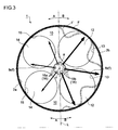
- FIG. 3 is a planar view of a cylinder head of the precombustion-chamber gas engine according to one embodiment of the present invention as seen from below.
- the precombustion-chamber gas engine 1 of the present invention basically has the same configuration as that of the above described embodiment. Thus, the same components are indicated by the same reference signs to omit detailed description.
- the precombustion-chamber gas engine 1 illustrated in FIG. 3 is different from the one in the above embodiment in that the nozzle holes 16 disposed on the precombustion-chamber cap 8 have different arrangement and shapes.
- the precombustion-chamber cap 8 of the present embodiment includes six nozzle holes 16 similarly to the above embodiment. However, three intake-side nozzle holes 16b and three exhaust-side nozzle holes 16a are arranged and the nozzle-hole area of each intake-side nozzle hole 16b is larger than that of each exhaust-side nozzle hole 16a, unlike the above embodiment.
- the nozzle-hole diameter of each of the above three intake-side nozzle holes 16b is larger than the nozzle-hole diameter of each of the above three exhaust-side nozzle holes 16a, so that the total area of the above intake-side nozzle holes 16b is larger than that of the above three exhaust-side nozzle holes 16a.
- each torch jet “f” in FIG. 3 indicates the injecting direction and the strength of the penetration force of the torch jet "f".
- the arrows indicate that the torch jets "fb” injected from the intake-side nozzle holes 16b are injected with larger penetration forces than the torch jets "fa” injected from the exhaust-side nozzle holes 16a.
- the penetration forces of the torch jets "fb” injected from the intake-side nozzle holes 16b into the intake-side region (B) are larger than the penetration forces of the torch jets "fa” injected from the exhaust-side nozzle holes 16a when the nozzle-hole diameter of each intake-side nozzle hole 16b is larger than that of each exhaust-side nozzle hole 16a, i.e., when the total nozzle-hole area of the intake-side nozzle holes 16b is larger than that of the exhaust-side nozzle holes 16a.
- each torch jet "fb" in the intake-side region (B) is long, and accordingly, the propagation distance of the flames propagating from the torch jets "fb” is short. As a result, the flames also reach the cylinder wall surface 2b in a short period of time.
- the temporal difference is small between the time in which the flames propagate from the torch jets "fb” injected from the intake-side nozzle holes 16b to reach the cylinder wall surface 2b of the intake-side region (B) and the time in which the flames propagate from the torch jets "fa” injected from the exhaust-side nozzle holes 16a to reach the cylinder wall surface 2a of the exhaust-side region (A).
- the flame surface F reaches the cylinder wall surfaces 2a, 2b substantially at the same time in the intake-side region (B) and the exhaust-side region (A), unlike the conventional flame surface F'.
- occurrence of knocking in the vicinity of the cylinder wall surface 2b is restricted.
- the precombustion-chamber cap 8 in a case where the number of the intake-side nozzle holes 16b is the same as that of the exhaust-side nozzle holes 16a while the nozzle-hole area of each intake-side nozzle hole 16b is larger than that of each exhaust-side nozzle hole 16a, it is possible to form the precombustion-chamber cap 8 according to one embodiment of the present invention only by increasing the hole diameter of the nozzle holes 106 arranged to be oriented to the intake-side region (B) on the conventional precombustion-chamber cap 108 illustrated in FIG. 4 , where nozzle holes having an identical area are formed at equal intervals, for instance. As a result, it is possible to easily manufacture the precombustion-chamber cap 8.
- the present invention is not limited to the above embodiments where the following two cases are described.
- the number of the intake-side nozzle holes 16b is the same as that of the exhaust-side nozzle holes 16a, and the total nozzle-hole area of the intake-side nozzle holes 16b is larger than that of the exhaust-side nozzle holes 16a.
- the number of the intake-side nozzle holes 16b is larger than that of the exhaust-side nozzle holes 16a, and the nozzle-hole area of each intake-side nozzle hole 16b is the same as that of each exhaust-side nozzle hole 16a.
- the present invention may only require that the total nozzle-hole area of the intake-side nozzle holes 16b is larger than that of the exhaust-side nozzle holes 16a.
- the number of intake-side nozzle holes 16b is larger than that of the exhaust-side nozzle holes 16a
- the total nozzle-hole area of the intake-side nozzle holes 16b is larger than that of the exhaust-side nozzle holes 16a.
- At least one embodiment of the present invention provides a precombustion-chamber gas engine which combusts mixed air in a main combustion chamber by injecting combustion flames, produced in a precombustion chamber formed inside a precombustion-chamber cap, into the main combustion chamber through a plurality of nozzle holes.
- This precombustion-chamber gas engine can be used in, for instance, a power-generation gas engine in a thermal power generating plant.
Landscapes
- Engineering & Computer Science (AREA)
- Chemical & Material Sciences (AREA)
- Combustion & Propulsion (AREA)
- Mechanical Engineering (AREA)
- General Engineering & Computer Science (AREA)
- Combustion Methods Of Internal-Combustion Engines (AREA)
Abstract
Description
- The present disclosure relates to a precombustion-chamber gas engine that combusts mixed air in a main combustion chamber by injecting combustion flames into the main combustion chamber through a plurality of nozzle holes. The combustion flames are produced in a precombustion chamber disposed inside a precombustion chamber cap.
-
FIG. 4 is a planar view of a cylinder head of a conventional precombustion-chamber gas engine as seen from below. This conventional precombustion-chamber gas engine 100 includes aprecombustion chamber cap 108 disposed inside thecylinder head 104 at the center of thecylinder head 104, as illustrated inFIG. 4 . Twointake ports 113 and twoexhaust ports 115 are opened around theprecombustion chamber cap 108 of thecylinder head 104 so as to surround theprecombustion chamber cap 108. InFIG. 4 , twointake ports 113 are opened on the right side of the drawing, while twoexhaust ports 115 are opened on the left side of the drawing. - Furthermore, the above two
intake ports 113 and twoexhaust ports 115 are opened and closed byintake valves 112 andexhaust valve 114, respectively. Theintake valves 112 open and close theintake ports 113 so that mixed air is supplied to themain combustion chamber 110 delimited between thecylinder head 104 and a top face of a non-illustrated piston. Theexhaust valves 114 open and close theexhaust ports 115 so that exhaust gas in themain combustion chamber 110 is discharged. - A
precombustion chamber 120 is delimited inside theprecombustion chamber cap 108. Theprecombustion chamber cap 108 includes a plurality ofnozzle holes 116 that brings theprecombustion chamber 120 into communication with themain combustion chamber 110. Sixnozzle holes 116 are provided at equal intervals in the circumferential direction. The combustion flames "f" (hereinafter, referred to as torch jets) produced in theprecombustion chamber 120 are injected into themain combustion chamber 110 through thenozzle holes 116, thereby combusting mixed air in themain combustion chamber 110. The arrows here of the torch jets "f" inFIG. 4 indicate the injecting direction and the strength of the penetration force of the torch jets "f". The torch jets "f" in the drawing indicate that they are injected evenly in terms of space and at the same penetration force inside themain combustion chamber 110. - Patent Document 1: Japanese Unexamined Patent Application No.
2004-251213 - Meanwhile, the inventors found that knocking tends to occur in a partial region of the
main combustion chamber 110 in the conventional precombustion-chamber gas engine 100 with the above configuration. They conducted researches and the like to determine the cause. As a result, they found out that one cause is the uneven distribution of the flame propagation speed of the mixed air in the main combustion chamber ignited by the torch jets "f" due to the low temperature of thecylinder wall surface 102b in an intake-side region (region "B" inFIG. 4 ) where theintake ports 113 are provided compared to the temperature of thecylinder wall surface 102a in an exhaust-side region (region "A" inFIG. 4 ) where theexhaust ports 115 are provided. - In other words, the flame propagation speed of the mixed air is low in the intake-side region (B), where the mixed air is ignited by torch jets "fb" injected from the
nozzle holes 116b disposed so as to face the intake-side region (B), as compared to the flame propagation speed of the mixed air in the exhaust-side region, where the mixed air is ignited by torch jets "fa" injected from thenozzle holes 116a disposed so as to face the exhaust-side region (A), corresponding to the low temperature of the cylinder wall surface in the intake-side region (B) compared to the exhaust-side region (A). Thus, as illustrated inFIG. 4 , even immediately before the torch jets "fa" reach thecylinder wall surface 102a in the exhaust-side region (A), mixed air still remains as non-combusted gas in a partial region in the vicinity of thecylinder wall surface 102b having a low wall-surface temperature. Specifically, the partial region is the outside region of the flame surface F'. This non-combusted gas self ignites to cause knocking (see reference sign "K" inFIG. 4 ). -
Patent Document 1 discloses an invention in which a combustion-chamber internal combustion engine includes a main combustion chamber and a precombustion chamber, and nozzle holes are arranged outwardly in the radial direction by a half length or more of the radius, so that combustion flames securely reach a top clearance part where non-combusted gas is likely to be produced. This invention ofPatent Document 1, however, does not prevent knocking due to the temperature difference between an intake-side region (B) and an exhaust-side region (A). - At least one embodiment of the present invention was made in view of the above issue. An object is to provide a precombustion-chamber gas engine where occurrence of knocking is restricted.
- In order to achieve the above object, at least one embodiment of the present invention provides a precombustion-chamber gas engine including: a cylinder; a cylinder head disposed on a top portion of the cylinder; a piston reciprocably disposed inside the cylinder, the piston delimiting a main combustion chamber with the cylinder head; a precombustion-chamber cap disposed inside the cylinder head at the center part of the cylinder head, the precombustion-chamber cap delimiting a precombustion chamber inside the precombustion-chamber cap and including a plurality of nozzle holes through which the precombustion chamber is in communication with the main combustion chamber; an intake valve for supplying mixed air to the main combustion chamber by opening and closing an intake port that opens on the cylinder head; and an exhaust valve for discharging exhaust gas in the main combustion chamber by opening and closing an exhaust port that opens on the cylinder head. When dividing the main combustion chamber into two regions including an intake-side region having the intake port and an exhaust-side region having the exhaust port and defining at least one nozzle hole arranged to be oriented to the intake-side region as at least one intake-side nozzle hole and at least one nozzle hole arranged to be oriented to the exhaust-side region as at least one exhaust-side nozzle hole from among the plurality of nozzle holes disposed on the precombustion-chamber cap, in a planar view where the cylinder head is seen from below, a total nozzle-hole area of the at least one intake-side nozzle hole is larger than a total nozzle-hole area of the at least one exhaust-side nozzle hole.
- In the precombustion-chamber gas engine with the above configuration, the total nozzle-hole area of the at least one intake-side nozzle hole is larger than the total nozzle-hole area of the at least one exhaust-side nozzle hole. Thus, the flames of the intake-side mixed air, having been ignited by torch jets injected from the intake-side nozzle holes, reach the cylinder wall surface in a shorter period of time. As a result, it is possible to restrict occurrence of knocking.
- In other words, the above configuration includes following two cases. (1) In the first case, the number of the intake-side nozzle holes is larger than that of the exhaust-side nozzle holes, so that the propagation area of the flame propagating from the torch jet injected from each intake-side nozzle holes is narrow (i.e., the propagation distance is short). Thus, a combustion flame reaches the cylinder wall surface in a shorter period of time. (2) In the second case, the number of the intake-side nozzle holes is the same as that of the exhaust-side nozzle holes. Still, the total nozzle-hole area of the intake-side nozzle holes is larger than that of the exhaust-side nozzle holes, so that the penetration force of the torch jet injected from each intake-side nozzle hole is large and therefore the development distance of the torch jet is large, causing the propagation distance of the flames propagating from the torch jets to become short. Thus, a combustion flame reaches the cylinder wall surface in a shorter period of time.
- Further, in the precombustion-chamber gas engine of one embodiment of the present invention, the number of the at least one intake-side nozzle hole is larger than the number of the at least one exhaust-side nozzle hole, and the at least one intake-side nozzle hole and the at least one exhaust-side nozzle hole each have an identical nozzle-hole area.
- When the at least one intake-side nozzle hole and the at least one exhaust-side nozzle hole each have an identical nozzle-hole area as described above, forming the nozzle holes on the precombustion chamber cap is facilitated.
- Further, in the precombustion-chamber gas engine of one embodiment of the present invention, the number of the at least one intake-side nozzle hole is equal to the number of the at least one exhaust-side nozzle hole, and each of the at least one intake-side nozzle hole has a nozzle hole area larger than a nozzle hole area of each of the at least one exhaust-side nozzle hole.
- As described above, the number of the at least one intake-side nozzle hole is equal to the number of the at least one exhaust-side nozzle hole, and each of the at least one intake-side nozzle hole has a nozzle hole area larger than a nozzle hole area of each of the at least one exhaust-side nozzle hole. In this way, for instance, it is possible to form the precombustion chamber cap according to one embodiment of the present invention by only increasing the diameter of the nozzle holes arranged to face the intake-side region on a conventional combustion chamber cap where nozzle holes of an identical area are formed at equal intervals. Thus, it is possible to easily manufacture the precombustion chamber cap.
- According to one embodiment of the present invention, it is possible to shorten the period of time in which the combustion flames injected from the intake-side nozzle holes reach the cylinder wall surface. Thus, it is possible to provide a precombustion-chamber gas engine in which occurrence of knocking is restricted.
-
-
FIG. 1 is a cross-sectional view of a precombustion-chamber gas engine according to one embodiment of the present invention. -
FIG. 2 is a planar view of a cylinder head of the precombustion-chamber gas engine according to one embodiment of the present invention as seen from below. -
FIG. 3 is a planar view of a cylinder head of the precombustion-chamber gas engine according to one embodiment of the present invention as seen from below. -
FIG. 4 is a planar view of a cylinder head of a conventional precombustion-chamber gas engine as seen from below. - Embodiments of the present invention will now be described in detail with reference to the accompanying drawings. It is intended, however, that unless particularly specified, dimensions, materials, shapes, relative positions and the like of components described in the embodiments shall be interpreted as illustrative only and not limitative of the scope of the present invention.
-
FIG. 1 is a cross-sectional view of a precombustion-chamber gas engine according to one embodiment of the present invention.FIG. 2 is a planar view of a cylinder head of the precombustion-chamber gas engine according to one embodiment of the present invention as seen from below. - As illustrated in
FIG. 1 , a precombustion-chamber gas engine 1 according to one embodiment of the present invention includes acylinder 2 of a cylindrical shape, acylinder head 4 disposed on the top of thecylinder 2, and apiston 6 disposed reciprocably inside thecylinder 2. Amain combustion chamber 10 is delimited between thecylinder head 4 and thetop face 6a of thepiston 6. - Further, a precombustion-
chamber cap 8 is provided inside thecylinder head 4 at the center part of thecylinder head 4. Aprecombustion chamber 20 is delimited inside the precombustion-chamber cap 8. An ignition plug 18 is disposed on the upper portion of theprecombustion chamber 20, while a fuel-gas passage (not illustrated) is also connected to the upper portion. In this way, fuel gas for ignition is supplied to theprecombustion chamber 20 through the fuel-gas passage. Further, the precombustion-chamber cap 8 is disposed inside thecylinder head 4 while having a portion projecting into themain combustion chamber 10. This projecting portion includes a plurality of nozzle holes 16 which brings themain combustion chamber 10 into communication with theprecombustion chamber 20. In the present embodiment, sixnozzle holes 16 are provided. - Further,
intake ports 13 andexhaust ports 15 are each opened on thecylinder head 4.Supply valves 12 andexhaust valves 14 for opening and closing theintake ports 13 and theexhaust ports 15, respectively, are also disposed on thecylinder head 4. - The
intake ports 13 are in communication with a gas mixer (not illustrated) in which fuel gas and air are premixed. Then, theintake valves 12 are opened in an intake stroke so that mixed air that has been premixed in the gas mixer is supplied to themain combustion chamber 10 through theintake ports 13. - Further, the
exhaust ports 15 are in communication with an exhaust manifold (not illustrated). Theexhaust valves 14 are opened in an exhaust stroke so that the fuel gas in themain combustion chamber 10 is discharged through theexhaust ports 15. - As illustrated in
FIG. 2 , twointake ports 13 and twoexhaust ports 15 are disposed so as to encompass the periphery of theprecombustion chamber cap 8. In the present embodiment, twointake ports 13 open at the right side of the drawing, while twoexhaust ports 15 are disposed on the left side of the drawing. - Here, the
main combustion chamber 10 is divided into two regions in a planar view in which thecylinder head 4 is seen from below, as illustrated inFIG. 4 . The two regions are an intake-side region (B) including theintake ports 13 and an exhaust-side region (A) including theexhaust ports 15. InFIG. 2 , a boundary L between the intake-side region (B) and the exhaust-side region (A) is defined as a straight line that passes through the center point O and evenly divides themain combustion chamber 10 into the intake-side region (B) including the twointake ports 13, and the exhaust-side region (A) including the twoexhaust ports 15. - From among the plurality of nozzle holes 16 disposed on the
precombustion chamber cap 8, the nozzle holes 16 oriented to the intake-side region (B) are defined as intake-side nozzle holes 16b, while the nozzle holes 16 oriented to the exhaust-side region (A) are defined as exhaust-side nozzle holes 16a. - In this case, in the precombustion-chamber gas engine according to one embodiment of the present invention, four intake-side nozzle holes 16b are arranged to be oriented to the intake-side region (B) and two exhaust-
side nozzle holes 16a are arranged to be oriented to the exhaust-side region (A), from among the sixnozzle holes 16 disposed on the precombustion-chamber cap 8, as illustrated inFIG. 2 . - Further in this case, the above described four intake-side nozzle holes 16b and two exhaust-
side nozzle holes 16a are each formed to have an identical nozzle-hole area. Thus, the total nozzle-hole area of the above two intake-side nozzle holes 16b is larger than the total nozzle-hole area of the above four exhaust-side nozzle holes 16a. - In the precombustion-
chamber gas engine 1 with the above configuration according to one embodiment of the present invention, fuel gas for ignition supplied to theprecombustion chamber 20 is ignited by theignition plug 18 to produce a combustion flame in theprecombustion chamber 20. The combustion flames produced in theprecombustion chamber 20 are injected into themain combustion chamber 10 through the nozzle holes 16 to form torch jets "f". Then, the combustion flames ignite the mixed air in themain combustion chamber 10 so that flames propagate to cause combustion throughout the entiremain combustion chamber 10. - In the present embodiment, the number of the intake-
side nozzle holes 16b is larger than that of the exhaust-side nozzle holes 16a, so that the total nozzle-hole area of the intake-side nozzle holes 16b is larger than that of the exhaust-side nozzle holes 16a, as described above. When the number of the intake-side nozzle holes 16b is larger than that of the exhaust-side nozzle holes 16a as described above, the propagation region of the flame propagating from each injected torch jet "fb" through the intake-side region (B) is narrow (i.e., the propagation distance is short). Thus, the flames reach acylinder wall surface 2b in a shorter period of time. - As a result, the temporal difference is small between the time in which the flames propagate from the torch jets "fb" injected from the intake-side nozzle holes 16b to reach the
cylinder wall surface 2b of the intake-side region (B) and the time in which the flames propagate from the torch jets "fa" injected from the exhaust-side nozzle holes 16a to reach thecylinder wall surface 2a of the exhaust-side region (A). As illustrated inFIG. 2 , the flame surface F reaches thecylinder wall surfaces cylinder wall surface 2b is restricted. - Further, in a case where the intake-side nozzle holes 16b and the exhaust-
side nozzle holes 16a each have an identical nozzle-hole area as described above, it is possible to form nozzle holes 16 by opening holes of the same shape on the precombustion-chamber cap 8 when forming the nozzle holes 16 on the precombustion-chamber cap 8. Thus, forming the nozzle holes 16 on the precombustion-chamber cap 8 is facilitated. -
FIG. 3 is a planar view of a cylinder head of the precombustion-chamber gas engine according to one embodiment of the present invention as seen from below. The precombustion-chamber gas engine 1 of the present invention basically has the same configuration as that of the above described embodiment. Thus, the same components are indicated by the same reference signs to omit detailed description. - The precombustion-
chamber gas engine 1 illustrated inFIG. 3 is different from the one in the above embodiment in that the nozzle holes 16 disposed on the precombustion-chamber cap 8 have different arrangement and shapes. Specifically, the precombustion-chamber cap 8 of the present embodiment includes sixnozzle holes 16 similarly to the above embodiment. However, three intake-side nozzle holes 16b and three exhaust-side nozzle holes 16a are arranged and the nozzle-hole area of each intake-side nozzle hole 16b is larger than that of each exhaust-side nozzle hole 16a, unlike the above embodiment. That is, the nozzle-hole diameter of each of the above three intake-side nozzle holes 16b is larger than the nozzle-hole diameter of each of the above three exhaust-side nozzle holes 16a, so that the total area of the above intake-side nozzle holes 16b is larger than that of the above three exhaust-side nozzle holes 16a. - Here, the arrow of each torch jet "f" in
FIG. 3 indicates the injecting direction and the strength of the penetration force of the torch jet "f". The arrows indicate that the torch jets "fb" injected from the intake-side nozzle holes 16b are injected with larger penetration forces than the torch jets "fa" injected from the exhaust-side nozzle holes 16a. - As described above, even though the number of the intake-
side nozzle holes 16b is the same as that of the exhaust-side nozzle holes 16a, the penetration forces of the torch jets "fb" injected from the intake-side nozzle holes 16b into the intake-side region (B) are larger than the penetration forces of the torch jets "fa" injected from the exhaust-side nozzle holes 16a when the nozzle-hole diameter of each intake-side nozzle hole 16b is larger than that of each exhaust-side nozzle hole 16a, i.e., when the total nozzle-hole area of the intake-side nozzle holes 16b is larger than that of the exhaust-side nozzle holes 16a. Thus, the reach of each torch jet "fb" in the intake-side region (B) is long, and accordingly, the propagation distance of the flames propagating from the torch jets "fb" is short. As a result, the flames also reach thecylinder wall surface 2b in a short period of time. - In consequence, the temporal difference is small between the time in which the flames propagate from the torch jets "fb" injected from the intake-side nozzle holes 16b to reach the
cylinder wall surface 2b of the intake-side region (B) and the time in which the flames propagate from the torch jets "fa" injected from the exhaust-side nozzle holes 16a to reach thecylinder wall surface 2a of the exhaust-side region (A). As illustrated inFIG. 3 , the flame surface F reaches thecylinder wall surfaces cylinder wall surface 2b is restricted. - Further, in a case where the number of the intake-
side nozzle holes 16b is the same as that of the exhaust-side nozzle holes 16a while the nozzle-hole area of each intake-side nozzle hole 16b is larger than that of each exhaust-side nozzle hole 16a, it is possible to form the precombustion-chamber cap 8 according to one embodiment of the present invention only by increasing the hole diameter of the nozzle holes 106 arranged to be oriented to the intake-side region (B) on the conventional precombustion-chamber cap 108 illustrated inFIG. 4 , where nozzle holes having an identical area are formed at equal intervals, for instance. As a result, it is possible to easily manufacture the precombustion-chamber cap 8. - Embodiments of the present invention were described in detail above, but the present invention is not limited thereto, and various amendments and modifications may be implemented within a scope that does not depart from the present invention.
- For instance, the present invention is not limited to the above embodiments where the following two cases are described. (1) In the first case, the number of the intake-
side nozzle holes 16b is the same as that of the exhaust-side nozzle holes 16a, and the total nozzle-hole area of the intake-side nozzle holes 16b is larger than that of the exhaust-side nozzle holes 16a. (2) In the second case, the number of the intake-side nozzle holes 16b is larger than that of the exhaust-side nozzle holes 16a, and the nozzle-hole area of each intake-side nozzle hole 16b is the same as that of each exhaust-side nozzle hole 16a. - That is, the present invention may only require that the total nozzle-hole area of the intake-
side nozzle holes 16b is larger than that of the exhaust-side nozzle holes 16a. For instance, there may be another case (3) where the number of intake-side nozzle holes 16b is larger than that of the exhaust-side nozzle holes 16a, and the total nozzle-hole area of the intake-side nozzle holes 16b is larger than that of the exhaust-side nozzle holes 16a. - At least one embodiment of the present invention provides a precombustion-chamber gas engine which combusts mixed air in a main combustion chamber by injecting combustion flames, produced in a precombustion chamber formed inside a precombustion-chamber cap, into the main combustion chamber through a plurality of nozzle holes. This precombustion-chamber gas engine can be used in, for instance, a power-generation gas engine in a thermal power generating plant.
-
- 1
- Precombustion-chamber gas engine
- 2
- Cylinder
- 2a, 2b
- Cylinder wall surface
- 4
- Cylinder head
- 6
- Piston
- 6a
- Piston top surface
- 8
- Precombustion-chamber cap
- 10
- Main combustion chamber
- 12
- Intake valve
- 13
- Intake port
- 14
- Exhaust valve
- 15
- Exhaust port
- 16
- Nozzle hole
- 16a
- Exhaust-side nozzle hole
- 16b
- Intake-side nozzle hole
- 18
- Ignition plug
- 20
- Precombustion chamber
- F, F'
- Flame surface
- fa, fb
- Torch jet
Claims (3)
- A precombustion-chamber gas engine, comprising:a cylinder;a cylinder head disposed on a top portion of the cylinder;a piston reciprocably disposed inside the cylinder, the piston delimiting a main combustion chamber with the cylinder head;a precombustion-chamber cap disposed inside the cylinder head at the center part of the cylinder head, the precombustion-chamber cap delimiting a precombustion chamber inside the precombustion-chamber cap and including a plurality of nozzle holes through which the precombustion chamber is in communication with the main combustion chamber;an intake valve for supplying mixed air to the main combustion chamber by opening and closing an intake port that opens on the cylinder head; andan exhaust valve for discharging exhaust gas in the main combustion chamber by opening and closing an exhaust port that opens on the cylinder head,wherein,when dividing the main combustion chamber into two regions including an intake-side region having the intake port and an exhaust-side region having the exhaust port and defining at least one nozzle hole arranged to be oriented to the intake-side region as at least one intake-side nozzle hole and at least one nozzle hole arranged to be oriented to the exhaust-side region as at least one exhaust-side nozzle hole from among the plurality of nozzle holes disposed on the precombustion-chamber cap, in a planar view where the cylinder head is seen from below,a total nozzle-hole area of the at least one intake-side nozzle hole is larger than a total nozzle-hole area of the at least one exhaust-side nozzle hole.
- The precombustion-chamber gas engine according to claim 1,
wherein the number of the at least one intake-side nozzle hole is larger than the number of the at least one exhaust-side nozzle hole, and the at least one intake-side nozzle hole and the at least one exhaust-side nozzle hole each have an identical nozzle-hole area. - The precombustion-chamber gas engine according to claim 1,
wherein the number of the at least one intake-side nozzle hole is equal to the number of the at least one exhaust-side nozzle hole, and each of the at least one intake-side nozzle hole has a nozzle hole area larger than a nozzle hole area of each of the at least one exhaust-side nozzle hole.
Applications Claiming Priority (2)
| Application Number | Priority Date | Filing Date | Title |
|---|---|---|---|
| JP2012207340A JP6076662B2 (en) | 2012-09-20 | 2012-09-20 | Sub-chamber gas engine |
| PCT/JP2013/075309 WO2014046185A1 (en) | 2012-09-20 | 2013-09-19 | Prechamber gas engine |
Publications (3)
| Publication Number | Publication Date |
|---|---|
| EP2899381A4 EP2899381A4 (en) | 2015-07-29 |
| EP2899381A1 true EP2899381A1 (en) | 2015-07-29 |
| EP2899381B1 EP2899381B1 (en) | 2017-08-02 |
Family
ID=50341489
Family Applications (1)
| Application Number | Title | Priority Date | Filing Date |
|---|---|---|---|
| EP13839517.3A Not-in-force EP2899381B1 (en) | 2012-09-20 | 2013-09-19 | Prechamber gas engine |
Country Status (5)
| Country | Link |
|---|---|
| US (1) | US10202891B2 (en) |
| EP (1) | EP2899381B1 (en) |
| JP (1) | JP6076662B2 (en) |
| CN (1) | CN104508276B (en) |
| WO (1) | WO2014046185A1 (en) |
Cited By (1)
| Publication number | Priority date | Publication date | Assignee | Title |
|---|---|---|---|---|
| WO2022175586A1 (en) * | 2021-02-19 | 2022-08-25 | Wärtsilä Finland Oy | Prechamber arrangement, cylinder head and piston engine |
Families Citing this family (26)
| Publication number | Priority date | Publication date | Assignee | Title |
|---|---|---|---|---|
| US9353674B2 (en) * | 2010-11-01 | 2016-05-31 | Mahle Powertrain, Llc | Turbulent jet ignition pre-chamber combustion system for spark ignition engines |
| JP6076662B2 (en) | 2012-09-20 | 2017-02-08 | 三菱重工業株式会社 | Sub-chamber gas engine |
| EP2927458A1 (en) * | 2014-04-04 | 2015-10-07 | Caterpillar Energy Solutions GmbH | Pre-chamber with flow transfer passages |
| JP6478509B2 (en) | 2014-07-31 | 2019-03-06 | 株式会社Soken | Laser igniter |
| US9739192B2 (en) | 2015-05-04 | 2017-08-22 | Caterpillar Inc. | Fuel combustion system, nozzle for prechamber assembly with curved orifices, and method of making same |
| CN114439600A (en) | 2015-10-08 | 2022-05-06 | 康明斯公司 | Pre-chamber assembly |
| US10598079B2 (en) * | 2015-11-11 | 2020-03-24 | Cummins Inc. | Charge-fed pre-chamber assembly |
| JP6796471B2 (en) | 2016-12-08 | 2020-12-09 | 三菱重工エンジン&ターボチャージャ株式会社 | Sub-chamber gas engine |
| JP6895243B2 (en) | 2016-12-08 | 2021-06-30 | 三菱重工エンジン&ターボチャージャ株式会社 | Sub-chamber gas engine |
| JP6930829B2 (en) | 2016-12-12 | 2021-09-01 | 三菱重工エンジン&ターボチャージャ株式会社 | Sub-chamber gas engine |
| JP6795985B2 (en) * | 2017-01-13 | 2020-12-02 | 三菱重工業株式会社 | Sub-chamber gas engine |
| JP6762241B2 (en) * | 2017-01-24 | 2020-09-30 | 三菱重工業株式会社 | Sub-chamber gas engine |
| JP6565952B2 (en) * | 2017-02-13 | 2019-08-28 | トヨタ自動車株式会社 | Internal combustion engine |
| JP6562019B2 (en) | 2017-03-16 | 2019-08-21 | トヨタ自動車株式会社 | Internal combustion engine |
| JP2018172974A (en) * | 2017-03-31 | 2018-11-08 | 本田技研工業株式会社 | Internal combustion engine |
| JP6927084B2 (en) * | 2018-03-02 | 2021-08-25 | トヨタ自動車株式会社 | Internal combustion engine |
| JP7285795B2 (en) * | 2020-01-31 | 2023-06-02 | 三菱重工業株式会社 | engine |
| DE102020001382A1 (en) * | 2020-03-04 | 2021-09-09 | Daimler Ag | Pre-chamber spark plug for a combustion chamber of an internal combustion engine, internal combustion engine and motor vehicle |
| DE102020001385A1 (en) * | 2020-03-04 | 2021-09-09 | Daimler Ag | Pre-chamber spark plug for a combustion chamber of an internal combustion engine, internal combustion engine and motor vehicle |
| US11939905B2 (en) * | 2020-05-20 | 2024-03-26 | Board Of Trustees Of Michigan State University | Internal combustion engine including multiple fuel injections external to a pre-chamber |
| US11156147B1 (en) | 2020-12-02 | 2021-10-26 | Aramco Services Company | Prechamber device for internal combustion engine |
| US20220220921A1 (en) * | 2021-01-11 | 2022-07-14 | Aramco Services Company | Passive prechamber lean burn combustion system |
| US11739702B2 (en) * | 2021-02-23 | 2023-08-29 | Aramco Services Company | Reheated residual gas ignitor |
| WO2023055475A2 (en) | 2021-07-30 | 2023-04-06 | Board Of Trustees Of Michigan State University | Actuation system for an internal combustion engine |
| US11898516B2 (en) * | 2021-08-25 | 2024-02-13 | Caterpillar Inc. | Cylinder head having bore locations arranged for tight packaging of gas exchange and fuel system components |
| CN115750067B (en) * | 2022-11-09 | 2024-04-12 | 重庆长安汽车股份有限公司 | Combustion system and combustion method of hybrid gasoline engine, engine and vehicle |
Family Cites Families (102)
| Publication number | Priority date | Publication date | Assignee | Title |
|---|---|---|---|---|
| US1753253A (en) * | 1923-09-04 | 1930-04-08 | Theodore E Hammond | Internal-combustion engine and method of operating same |
| US2422610A (en) * | 1937-10-27 | 1947-06-17 | Bagnulo Albert | Engine with stratified mixture |
| US2884913A (en) * | 1958-03-14 | 1959-05-05 | Ralph M Heintz | Internal combustion engine |
| US3102521A (en) * | 1960-12-20 | 1963-09-03 | Fmc Corp | Combustion apparatus for an internal combustion engine |
| US4085713A (en) * | 1973-02-27 | 1978-04-25 | Nippon Soken, Inc. | Torch ignition internal combustion engine |
| US4080938A (en) * | 1974-11-13 | 1978-03-28 | Toyota Jidosha Kogyo Kabushiki Kaisha | Combustion apparatus for an internal combustion engine |
| DE2510176B1 (en) * | 1975-03-08 | 1976-08-26 | Daimler Benz Ag | FOUR-STROKE PISTON ENGINE WITH IGNITION CHAMBER |
| US4060058A (en) * | 1975-11-28 | 1977-11-29 | Ford Motor Company | Internal combustion engine control system |
| US4076000A (en) * | 1976-04-15 | 1978-02-28 | Toyota Jidosha Kogyo Kabushiki Kaisha | Internal combustion engine having an auxiliary combustion chamber without an intake valve |
| US4124000A (en) * | 1976-11-03 | 1978-11-07 | General Motors Corporation | Mixed cycle stratified charge engine with ignition antechamber |
| US4239023A (en) * | 1978-12-07 | 1980-12-16 | Ford Motor Company | Fuel injection system for dual combustion chamber engine |
| US4301825A (en) * | 1978-12-08 | 1981-11-24 | Ford Motor Company | Fuel flow control valve assembly |
| US4218993A (en) * | 1979-03-14 | 1980-08-26 | Blackburn Donald E | Method and apparatus for accomplishing flame ignition for an internal combustion engine |
| DE2916285C2 (en) * | 1979-04-21 | 1984-02-23 | Robert Bosch Gmbh, 7000 Stuttgart | Process for igniting lean fuel / air mixtures |
| US4270499A (en) * | 1979-05-03 | 1981-06-02 | General Motors Corporation | Diesel engine precombustion chambers |
| US4320727A (en) * | 1979-12-19 | 1982-03-23 | Artman Noel G | Process of fuel stratification within and venting of engine auxiliary combustion chamber |
| DE3148296A1 (en) * | 1981-01-17 | 1982-09-02 | Robert Bosch Gmbh, 7000 Stuttgart | COMBINED INTERNAL COMBUSTION ENGINE WITH AT LEAST ONE MAIN COMBUSTION CHAMBER AND ITS COMBINED COMBUSTION CHAMBER |
| US4483291A (en) * | 1982-04-07 | 1984-11-20 | Artman Noel G | Process of segregating air-fuel mass in engine auxiliary chamber |
| JPS58180719A (en) * | 1982-04-17 | 1983-10-22 | Honda Motor Co Ltd | Torch ignition type gasoline internal-combustion engine |
| US4467759A (en) * | 1982-10-14 | 1984-08-28 | Artman Noel G | Combined air intake passage and precombustion chamber for internal combustion engine |
| JPS60153420A (en) * | 1984-01-21 | 1985-08-12 | Mitsubishi Heavy Ind Ltd | Combustion chamber of double cell type engine |
| JPS62129514A (en) * | 1985-11-30 | 1987-06-11 | Isuzu Motors Ltd | Combustion chamber for internal combustion engine |
| DE3709976A1 (en) * | 1987-03-30 | 1988-10-20 | Dieter Dr Ing Kuhnert | METHOD AND SPARK PLUG FOR THE IGNITION OF VERY LOW FUEL-AIR MIXTURES, ESPECIALLY FOR GAS ENGINES |
| JP2721685B2 (en) | 1988-12-05 | 1998-03-04 | 三菱重工業株式会社 | Spark ignition gas engine |
| US5067458A (en) * | 1989-03-27 | 1991-11-26 | Caterpillar Inc. | Fuel combustion system and method of operation for an otto-cycle internal combustion engine |
| US4977873A (en) * | 1989-06-08 | 1990-12-18 | Clifford L. Elmore | Timing chamber ignition method and apparatus |
| US5024193A (en) * | 1990-02-06 | 1991-06-18 | Caterpillar Inc. | Fuel combustion system, method, and nozzle member therefor |
| US5050550A (en) * | 1990-07-11 | 1991-09-24 | Litang Gao | Hybrid step combustion system |
| US5105780A (en) * | 1990-08-08 | 1992-04-21 | Caterpillar Inc. | Ignition assisting device for internal combustion engines |
| US5085189A (en) * | 1991-03-20 | 1992-02-04 | Industrial Technology Research Institute | Air-assisted fuel injection applied in the two-stroke engine of flame-jet ignition type |
| WO1993008385A1 (en) * | 1991-10-14 | 1993-04-29 | The University Of Melbourne | Internal combustion engine ignition device |
| US5293851A (en) * | 1992-04-16 | 1994-03-15 | Cooper Industries, Inc. | Combustion system for gas engine other than dual fuel engine |
| US5222993A (en) * | 1992-09-28 | 1993-06-29 | Gas Research Institute | Ignition system for water-cooled gas engines |
| US5609130A (en) * | 1992-12-14 | 1997-03-11 | Transcom Gas Technologies Pty Ltd. | Non-return valve |
| US5392744A (en) * | 1993-03-12 | 1995-02-28 | Chrysler Corporation | Precombustion chamber for a double overhead camshaft internal combustion engine |
| JP3073118B2 (en) * | 1993-04-20 | 2000-08-07 | 株式会社日立製作所 | In-cylinder internal combustion engine |
| US5752481A (en) * | 1993-10-18 | 1998-05-19 | Valve Maintenance Corporation | Injection valve assembly for an internal combustion engine |
| EP0675272B1 (en) * | 1994-03-29 | 1997-08-06 | Dieter Dr. Kuhnert | Prechamber ignition device |
| JPH07293344A (en) | 1994-04-27 | 1995-11-07 | Isuzu Ceramics Kenkyusho:Kk | Heat shield type gas engine |
| US5570665A (en) * | 1995-04-04 | 1996-11-05 | Chrysler Corporation | Valve train for internal combustion engine |
| US5533476A (en) * | 1995-06-14 | 1996-07-09 | Dresser-Rand Company | Walled precombustion chamber unit |
| US5662082A (en) * | 1995-12-05 | 1997-09-02 | Compressor Engineering Corporation | Pre-combustion chamber for internal combustion engine and method of manufacture thereof |
| JPH09256850A (en) * | 1996-03-25 | 1997-09-30 | Isuzu Ceramics Kenkyusho:Kk | Sub-chamber gas engine |
| JPH1047096A (en) | 1996-07-31 | 1998-02-17 | Yanmar Diesel Engine Co Ltd | Fuel gas supply amount setting method for prechamber type gas engine |
| US5924402A (en) * | 1997-02-24 | 1999-07-20 | Chrysler Corporation | Pre-combustion chamber for an internal combustion engine |
| US5915351A (en) * | 1997-02-24 | 1999-06-29 | Chrysler Corporation | Insulated precombustion chamber |
| US5778849A (en) * | 1997-05-05 | 1998-07-14 | Chrysler Corporation | Insulated precombustion chamber |
| US5947076A (en) * | 1998-04-17 | 1999-09-07 | Caterpillar Inc. | Fuel combustion assembly for an internal combustion engine having an encapsulated spark plug for igniting lean gaseous fuel within a precombustion chamber |
| JP2000027781A (en) | 1998-07-08 | 2000-01-25 | Isuzu Ceramics Res Inst Co Ltd | Rotary pump and sub-chamber gas engine provided with the rotary pump |
| JP2000073769A (en) | 1998-09-03 | 2000-03-07 | Isuzu Ceramics Res Inst Co Ltd | Sub-chamber gas engine with gas fuel compression means |
| US6019081A (en) * | 1998-10-01 | 2000-02-01 | Caterpillar Inc. | Cooled pre-combustion chamber assembly |
| US6016785A (en) * | 1998-10-01 | 2000-01-25 | Caterpillar Inc. | Pre-combustion chamber assembly and method |
| US6065441A (en) * | 1998-12-02 | 2000-05-23 | Daimlerchrysler Corporation | Divided chamber diesel combustion system |
| JP2001227344A (en) * | 2000-02-14 | 2001-08-24 | Mitsubishi Heavy Ind Ltd | Nozzle hole structure of torch ignition-type gas engine |
| JP4368028B2 (en) * | 2000-03-22 | 2009-11-18 | 大阪瓦斯株式会社 | Torch ignition engine |
| US6575192B1 (en) * | 2000-11-03 | 2003-06-10 | Caterpillar Inc | Check valve for a prechamber assembly |
| US6513483B2 (en) * | 2001-02-07 | 2003-02-04 | Cooper Cameron Corporation | Pre-combustion chamber for an internal combustion engine |
| US6854439B2 (en) * | 2002-03-02 | 2005-02-15 | Jose Francisco Regueiro | Prechamber combustion system |
| DE10217996A1 (en) * | 2002-04-23 | 2003-11-13 | Man B & W Diesel Ag | Self-igniting mixture-compressing internal combustion engine and method for its operation |
| US6739289B2 (en) * | 2002-04-26 | 2004-05-25 | Caterpillar Inc | Method and apparatus for providing a hydrogen enriched fuel to combustion prechamber |
| FR2846046B1 (en) * | 2002-10-18 | 2006-06-16 | Peugeot Citroen Automobiles Sa | PRE-CHAMBER IGNITION DEVICE FOR INTERNAL COMBUSTION ENGINE, PRE-CHAMBER IGNITER, AND IGNITION METHOD |
| JP2004251213A (en) | 2003-02-20 | 2004-09-09 | Tokyo Gas Co Ltd | Subchamber internal combustion engine |
| AU2003232676A1 (en) * | 2003-05-30 | 2005-01-21 | In-Tae Johng | Ignition plugs for internal combustion engine |
| US7387103B2 (en) * | 2003-11-19 | 2008-06-17 | Dan Merritt | Internal combustion engine |
| JP2005264768A (en) * | 2004-03-17 | 2005-09-29 | Nissan Motor Co Ltd | Internal combustion engine |
| DE102004023409B4 (en) * | 2004-05-12 | 2007-05-16 | Gottfried Schubert | High-compression gasoline engine with throttle control, spark ignition and direct fuel injection into a pre-combustion chamber |
| NO322345B1 (en) * | 2004-09-27 | 2006-09-18 | Rolls Royce Marine As | Device at a front chamber of a gas engine |
| JP2006177248A (en) * | 2004-12-22 | 2006-07-06 | Nissan Motor Co Ltd | Divided chamber type internal combustion engine |
| US7100567B1 (en) * | 2005-03-30 | 2006-09-05 | Caterpillar Inc. | Method to extend lean ignition limit within internal combustion engine |
| US20060219210A1 (en) * | 2005-03-30 | 2006-10-05 | Brett Bailey | Internal combustion engine with variable volume prechamber |
| US7261097B2 (en) * | 2005-06-30 | 2007-08-28 | Caterpillar Inc | EGR system for spark-ignited gasoline engine |
| JP2007113534A (en) * | 2005-10-24 | 2007-05-10 | Nissan Motor Co Ltd | Sub-chamber internal combustion engine |
| US7398743B2 (en) * | 2005-12-27 | 2008-07-15 | Caterpillar Inc. | Compression ignition initiation device and internal combustion engine using same |
| JP4609357B2 (en) * | 2006-03-24 | 2011-01-12 | 日産自動車株式会社 | Sub-chamber internal combustion engine |
| CA2539711C (en) * | 2006-03-31 | 2009-06-09 | Westport Research Inc. | Method and apparatus of fuelling an internal combustion engine with hydrogen and methane |
| US8469009B2 (en) * | 2006-03-31 | 2013-06-25 | Westport Power Inc. | Method and apparatus of fuelling an internal combustion engine with hydrogen and methane |
| JP2007297942A (en) | 2006-04-28 | 2007-11-15 | Nissan Motor Co Ltd | Ignition device for internal combustion engine |
| US20090025669A1 (en) * | 2007-07-25 | 2009-01-29 | Gerald Filipek | Heat source supplied glow plug/plasma torch and optional spark plasma torch for accomplishing more efficient piston combustion |
| JP2009197704A (en) | 2008-02-22 | 2009-09-03 | Mitsubishi Heavy Ind Ltd | Sub-chamber type gas engine |
| US8544443B2 (en) * | 2008-03-12 | 2013-10-01 | Cameron International Corporation | Pre-chamber |
| US7743753B2 (en) * | 2008-03-31 | 2010-06-29 | Caterpillar Inc | Ignition system utilizing igniter and gas injector |
| DE102008062572A1 (en) * | 2008-12-16 | 2010-06-17 | Ge Jenbacher Gmbh & Co. Ohg | spark plug |
| EP2372142B8 (en) * | 2008-12-26 | 2018-09-12 | Mitsubishi Heavy Industries Engine & Turbocharger, Ltd. | Gas engine with bore cool holes having spark plug |
| AT508801B1 (en) * | 2009-10-07 | 2011-09-15 | Ge Jenbacher Gmbh & Co Ohg | BRENNKRAFTMASCHINENZÜNDVORRICHTUNG |
| US8662053B2 (en) * | 2009-12-22 | 2014-03-04 | Cummins Inc. | Pre-combustion device for an internal combustion engine |
| EP2520780A4 (en) * | 2009-12-28 | 2013-07-24 | Kawasaki Heavy Ind Ltd | AUXILIARY ROOM TYPE GAS ENGINE |
| AT509876B1 (en) * | 2010-08-20 | 2011-12-15 | Ge Jenbacher Gmbh & Co Ohg | pre-chamber system |
| JP2012047115A (en) | 2010-08-27 | 2012-03-08 | Toyota Industries Corp | Auxiliary chamber type gas engine |
| DE112011103649T5 (en) * | 2010-11-01 | 2013-08-22 | Mahle Powertrain, Llc | Prechamber combustion system with turbulent ignition jet for gasoline engines |
| US9353674B2 (en) * | 2010-11-01 | 2016-05-31 | Mahle Powertrain, Llc | Turbulent jet ignition pre-chamber combustion system for spark ignition engines |
| US8567369B2 (en) * | 2010-11-11 | 2013-10-29 | Cameron International Corporation | Spark ignited radical injection system |
| US9476347B2 (en) * | 2010-11-23 | 2016-10-25 | Woodward, Inc. | Controlled spark ignited flame kernel flow in fuel-fed prechambers |
| JP5357926B2 (en) * | 2010-12-27 | 2013-12-04 | 川崎重工業株式会社 | Sub-chamber gas engine |
| US8813716B2 (en) * | 2011-06-22 | 2014-08-26 | Caterpillar Motoren Gmbh & Co. Kg | Pre-combustion chamber tip |
| US9217360B2 (en) * | 2011-12-01 | 2015-12-22 | Cummins Intellectual Property, Inc. | Prechamber device for internal combustion engine |
| JP6076662B2 (en) | 2012-09-20 | 2017-02-08 | 三菱重工業株式会社 | Sub-chamber gas engine |
| US9200560B2 (en) * | 2013-01-11 | 2015-12-01 | Caterpillar Inc. | Gaseous common rail fuel system and high compression ratio engine using same |
| US9567896B2 (en) * | 2013-01-28 | 2017-02-14 | Sonex Research, Inc. | Method for modifying combustion chamber in a reciprocating piston internal combustion engine and resulting engine |
| US9567939B2 (en) * | 2013-01-28 | 2017-02-14 | Sonex Research, Inc. | Thermally stratified regenerative combustion chamber |
| JP6016682B2 (en) * | 2013-03-19 | 2016-10-26 | 三菱重工業株式会社 | Sub-chamber fuel supply device for gas internal combustion engine |
| US8839762B1 (en) * | 2013-06-10 | 2014-09-23 | Woodward, Inc. | Multi-chamber igniter |
| GB2522070A (en) * | 2014-01-14 | 2015-07-15 | Caterpillar Motoren Gmbh & Co | Gaseous fuel feeding system |
-
2012
- 2012-09-20 JP JP2012207340A patent/JP6076662B2/en not_active Expired - Fee Related
-
2013
- 2013-09-19 CN CN201380040297.8A patent/CN104508276B/en not_active Expired - Fee Related
- 2013-09-19 EP EP13839517.3A patent/EP2899381B1/en not_active Not-in-force
- 2013-09-19 US US14/418,915 patent/US10202891B2/en active Active
- 2013-09-19 WO PCT/JP2013/075309 patent/WO2014046185A1/en not_active Ceased
Cited By (1)
| Publication number | Priority date | Publication date | Assignee | Title |
|---|---|---|---|---|
| WO2022175586A1 (en) * | 2021-02-19 | 2022-08-25 | Wärtsilä Finland Oy | Prechamber arrangement, cylinder head and piston engine |
Also Published As
| Publication number | Publication date |
|---|---|
| US10202891B2 (en) | 2019-02-12 |
| CN104508276A (en) | 2015-04-08 |
| EP2899381A4 (en) | 2015-07-29 |
| JP2014062484A (en) | 2014-04-10 |
| US20150184578A1 (en) | 2015-07-02 |
| CN104508276B (en) | 2017-05-17 |
| WO2014046185A1 (en) | 2014-03-27 |
| EP2899381B1 (en) | 2017-08-02 |
| JP6076662B2 (en) | 2017-02-08 |
Similar Documents
| Publication | Publication Date | Title |
|---|---|---|
| EP2899381B1 (en) | Prechamber gas engine | |
| EP3061939B1 (en) | Prechamber type gas engine | |
| EP3056710B1 (en) | Piston for auxiliary chamber-type gas engine and auxiliary chamber-type gas engine | |
| EP3536924B1 (en) | Precombustion chamber gas engine | |
| US11566559B2 (en) | Precombustion chamber gas engine | |
| EP3505735B1 (en) | Internal combustion engine | |
| EP2975237B1 (en) | Pre-chamber bottom section, pre-chamber, cylinder device, method for mixing of gas and air and ignition of the gas-air -mixture in a pre-chamber and a method for substituting a pre-chamber | |
| EP3001009B1 (en) | Direct injection diesel engine | |
| US20150047620A1 (en) | Two-cycle gas engine | |
| EP3536925A1 (en) | Sub-chamber gas engine | |
| CN108691637B (en) | internal combustion engine | |
| CN107002548A (en) | Combustion chamber structure of direct injection engine | |
| JP5140836B2 (en) | Sub-chamber gas engine | |
| JP5263818B2 (en) | Sub-chamber gas engine | |
| JP2006177254A (en) | Combustion chamber structure of internal combustion engine | |
| JP6795985B2 (en) | Sub-chamber gas engine | |
| JP2015017554A (en) | Internal combustion engine | |
| JP2009180116A (en) | Combustion chamber of internal combustion engine | |
| JP2018115589A (en) | Internal combustion engine | |
| JP2018115588A (en) | Internal combustion engine | |
| JP2015163795A (en) | Two-cycle gas engine and fuel gas injection system for two-cycle gas engine |
Legal Events
| Date | Code | Title | Description |
|---|---|---|---|
| PUAI | Public reference made under article 153(3) epc to a published international application that has entered the european phase |
Free format text: ORIGINAL CODE: 0009012 |
|
| 17P | Request for examination filed |
Effective date: 20150127 |
|
| A4 | Supplementary search report drawn up and despatched |
Effective date: 20150617 |
|
| AK | Designated contracting states |
Kind code of ref document: A1 Designated state(s): AL AT BE BG CH CY CZ DE DK EE ES FI FR GB GR HR HU IE IS IT LI LT LU LV MC MK MT NL NO PL PT RO RS SE SI SK SM TR |
|
| AX | Request for extension of the european patent |
Extension state: BA ME |
|
| DAX | Request for extension of the european patent (deleted) | ||
| 17Q | First examination report despatched |
Effective date: 20160627 |
|
| GRAP | Despatch of communication of intention to grant a patent |
Free format text: ORIGINAL CODE: EPIDOSNIGR1 |
|
| INTG | Intention to grant announced |
Effective date: 20170330 |
|
| GRAS | Grant fee paid |
Free format text: ORIGINAL CODE: EPIDOSNIGR3 |
|
| GRAA | (expected) grant |
Free format text: ORIGINAL CODE: 0009210 |
|
| AK | Designated contracting states |
Kind code of ref document: B1 Designated state(s): AL AT BE BG CH CY CZ DE DK EE ES FI FR GB GR HR HU IE IS IT LI LT LU LV MC MK MT NL NO PL PT RO RS SE SI SK SM TR |
|
| REG | Reference to a national code |
Ref country code: CH Ref legal event code: EP Ref country code: AT Ref legal event code: REF Ref document number: 914750 Country of ref document: AT Kind code of ref document: T Effective date: 20170815 |
|
| REG | Reference to a national code |
Ref country code: IE Ref legal event code: FG4D |
|
| REG | Reference to a national code |
Ref country code: DE Ref legal event code: R096 Ref document number: 602013024557 Country of ref document: DE |
|
| REG | Reference to a national code |
Ref country code: NL Ref legal event code: MP Effective date: 20170802 |
|
| REG | Reference to a national code |
Ref country code: LT Ref legal event code: MG4D |
|
| PG25 | Lapsed in a contracting state [announced via postgrant information from national office to epo] |
Ref country code: LT Free format text: LAPSE BECAUSE OF FAILURE TO SUBMIT A TRANSLATION OF THE DESCRIPTION OR TO PAY THE FEE WITHIN THE PRESCRIBED TIME-LIMIT Effective date: 20170802 Ref country code: NO Free format text: LAPSE BECAUSE OF FAILURE TO SUBMIT A TRANSLATION OF THE DESCRIPTION OR TO PAY THE FEE WITHIN THE PRESCRIBED TIME-LIMIT Effective date: 20171102 Ref country code: NL Free format text: LAPSE BECAUSE OF FAILURE TO SUBMIT A TRANSLATION OF THE DESCRIPTION OR TO PAY THE FEE WITHIN THE PRESCRIBED TIME-LIMIT Effective date: 20170802 Ref country code: SE Free format text: LAPSE BECAUSE OF FAILURE TO SUBMIT A TRANSLATION OF THE DESCRIPTION OR TO PAY THE FEE WITHIN THE PRESCRIBED TIME-LIMIT Effective date: 20170802 Ref country code: HR Free format text: LAPSE BECAUSE OF FAILURE TO SUBMIT A TRANSLATION OF THE DESCRIPTION OR TO PAY THE FEE WITHIN THE PRESCRIBED TIME-LIMIT Effective date: 20170802 |
|
| PG25 | Lapsed in a contracting state [announced via postgrant information from national office to epo] |
Ref country code: IS Free format text: LAPSE BECAUSE OF FAILURE TO SUBMIT A TRANSLATION OF THE DESCRIPTION OR TO PAY THE FEE WITHIN THE PRESCRIBED TIME-LIMIT Effective date: 20171202 Ref country code: RS Free format text: LAPSE BECAUSE OF FAILURE TO SUBMIT A TRANSLATION OF THE DESCRIPTION OR TO PAY THE FEE WITHIN THE PRESCRIBED TIME-LIMIT Effective date: 20170802 Ref country code: BG Free format text: LAPSE BECAUSE OF FAILURE TO SUBMIT A TRANSLATION OF THE DESCRIPTION OR TO PAY THE FEE WITHIN THE PRESCRIBED TIME-LIMIT Effective date: 20171102 Ref country code: GR Free format text: LAPSE BECAUSE OF FAILURE TO SUBMIT A TRANSLATION OF THE DESCRIPTION OR TO PAY THE FEE WITHIN THE PRESCRIBED TIME-LIMIT Effective date: 20171103 Ref country code: LV Free format text: LAPSE BECAUSE OF FAILURE TO SUBMIT A TRANSLATION OF THE DESCRIPTION OR TO PAY THE FEE WITHIN THE PRESCRIBED TIME-LIMIT Effective date: 20170802 Ref country code: PL Free format text: LAPSE BECAUSE OF FAILURE TO SUBMIT A TRANSLATION OF THE DESCRIPTION OR TO PAY THE FEE WITHIN THE PRESCRIBED TIME-LIMIT Effective date: 20170802 Ref country code: ES Free format text: LAPSE BECAUSE OF FAILURE TO SUBMIT A TRANSLATION OF THE DESCRIPTION OR TO PAY THE FEE WITHIN THE PRESCRIBED TIME-LIMIT Effective date: 20170802 |
|
| PG25 | Lapsed in a contracting state [announced via postgrant information from national office to epo] |
Ref country code: RO Free format text: LAPSE BECAUSE OF FAILURE TO SUBMIT A TRANSLATION OF THE DESCRIPTION OR TO PAY THE FEE WITHIN THE PRESCRIBED TIME-LIMIT Effective date: 20170802 Ref country code: DK Free format text: LAPSE BECAUSE OF FAILURE TO SUBMIT A TRANSLATION OF THE DESCRIPTION OR TO PAY THE FEE WITHIN THE PRESCRIBED TIME-LIMIT Effective date: 20170802 Ref country code: CZ Free format text: LAPSE BECAUSE OF FAILURE TO SUBMIT A TRANSLATION OF THE DESCRIPTION OR TO PAY THE FEE WITHIN THE PRESCRIBED TIME-LIMIT Effective date: 20170802 |
|
| REG | Reference to a national code |
Ref country code: CH Ref legal event code: PL |
|
| REG | Reference to a national code |
Ref country code: DE Ref legal event code: R097 Ref document number: 602013024557 Country of ref document: DE |
|
| PG25 | Lapsed in a contracting state [announced via postgrant information from national office to epo] |
Ref country code: EE Free format text: LAPSE BECAUSE OF FAILURE TO SUBMIT A TRANSLATION OF THE DESCRIPTION OR TO PAY THE FEE WITHIN THE PRESCRIBED TIME-LIMIT Effective date: 20170802 Ref country code: MC Free format text: LAPSE BECAUSE OF FAILURE TO SUBMIT A TRANSLATION OF THE DESCRIPTION OR TO PAY THE FEE WITHIN THE PRESCRIBED TIME-LIMIT Effective date: 20170802 Ref country code: IT Free format text: LAPSE BECAUSE OF FAILURE TO SUBMIT A TRANSLATION OF THE DESCRIPTION OR TO PAY THE FEE WITHIN THE PRESCRIBED TIME-LIMIT Effective date: 20170802 Ref country code: SM Free format text: LAPSE BECAUSE OF FAILURE TO SUBMIT A TRANSLATION OF THE DESCRIPTION OR TO PAY THE FEE WITHIN THE PRESCRIBED TIME-LIMIT Effective date: 20170802 Ref country code: SK Free format text: LAPSE BECAUSE OF FAILURE TO SUBMIT A TRANSLATION OF THE DESCRIPTION OR TO PAY THE FEE WITHIN THE PRESCRIBED TIME-LIMIT Effective date: 20170802 |
|
| PLBE | No opposition filed within time limit |
Free format text: ORIGINAL CODE: 0009261 |
|
| STAA | Information on the status of an ep patent application or granted ep patent |
Free format text: STATUS: NO OPPOSITION FILED WITHIN TIME LIMIT |
|
| REG | Reference to a national code |
Ref country code: IE Ref legal event code: MM4A |
|
| REG | Reference to a national code |
Ref country code: BE Ref legal event code: MM Effective date: 20170930 |
|
| PG25 | Lapsed in a contracting state [announced via postgrant information from national office to epo] |
Ref country code: LU Free format text: LAPSE BECAUSE OF NON-PAYMENT OF DUE FEES Effective date: 20170919 |
|
| REG | Reference to a national code |
Ref country code: FR Ref legal event code: ST Effective date: 20180531 |
|
| 26N | No opposition filed |
Effective date: 20180503 |
|
| GBPC | Gb: european patent ceased through non-payment of renewal fee |
Effective date: 20171102 |
|
| PG25 | Lapsed in a contracting state [announced via postgrant information from national office to epo] |
Ref country code: LI Free format text: LAPSE BECAUSE OF NON-PAYMENT OF DUE FEES Effective date: 20170930 Ref country code: IE Free format text: LAPSE BECAUSE OF NON-PAYMENT OF DUE FEES Effective date: 20170919 Ref country code: CH Free format text: LAPSE BECAUSE OF NON-PAYMENT OF DUE FEES Effective date: 20170930 |
|
| PG25 | Lapsed in a contracting state [announced via postgrant information from national office to epo] |
Ref country code: FR Free format text: LAPSE BECAUSE OF NON-PAYMENT OF DUE FEES Effective date: 20171002 Ref country code: SI Free format text: LAPSE BECAUSE OF FAILURE TO SUBMIT A TRANSLATION OF THE DESCRIPTION OR TO PAY THE FEE WITHIN THE PRESCRIBED TIME-LIMIT Effective date: 20170802 Ref country code: BE Free format text: LAPSE BECAUSE OF NON-PAYMENT OF DUE FEES Effective date: 20170930 |
|
| PG25 | Lapsed in a contracting state [announced via postgrant information from national office to epo] |
Ref country code: MT Free format text: LAPSE BECAUSE OF NON-PAYMENT OF DUE FEES Effective date: 20170919 |
|
| PG25 | Lapsed in a contracting state [announced via postgrant information from national office to epo] |
Ref country code: GB Free format text: LAPSE BECAUSE OF NON-PAYMENT OF DUE FEES Effective date: 20171102 |
|
| PG25 | Lapsed in a contracting state [announced via postgrant information from national office to epo] |
Ref country code: HU Free format text: LAPSE BECAUSE OF FAILURE TO SUBMIT A TRANSLATION OF THE DESCRIPTION OR TO PAY THE FEE WITHIN THE PRESCRIBED TIME-LIMIT; INVALID AB INITIO Effective date: 20130919 |
|
| PG25 | Lapsed in a contracting state [announced via postgrant information from national office to epo] |
Ref country code: CY Free format text: LAPSE BECAUSE OF FAILURE TO SUBMIT A TRANSLATION OF THE DESCRIPTION OR TO PAY THE FEE WITHIN THE PRESCRIBED TIME-LIMIT Effective date: 20170802 |
|
| PG25 | Lapsed in a contracting state [announced via postgrant information from national office to epo] |
Ref country code: MK Free format text: LAPSE BECAUSE OF FAILURE TO SUBMIT A TRANSLATION OF THE DESCRIPTION OR TO PAY THE FEE WITHIN THE PRESCRIBED TIME-LIMIT Effective date: 20170802 |
|
| PG25 | Lapsed in a contracting state [announced via postgrant information from national office to epo] |
Ref country code: TR Free format text: LAPSE BECAUSE OF FAILURE TO SUBMIT A TRANSLATION OF THE DESCRIPTION OR TO PAY THE FEE WITHIN THE PRESCRIBED TIME-LIMIT Effective date: 20170802 |
|
| PG25 | Lapsed in a contracting state [announced via postgrant information from national office to epo] |
Ref country code: PT Free format text: LAPSE BECAUSE OF FAILURE TO SUBMIT A TRANSLATION OF THE DESCRIPTION OR TO PAY THE FEE WITHIN THE PRESCRIBED TIME-LIMIT Effective date: 20170802 |
|
| PG25 | Lapsed in a contracting state [announced via postgrant information from national office to epo] |
Ref country code: AL Free format text: LAPSE BECAUSE OF FAILURE TO SUBMIT A TRANSLATION OF THE DESCRIPTION OR TO PAY THE FEE WITHIN THE PRESCRIBED TIME-LIMIT Effective date: 20170802 |
|
| PGFP | Annual fee paid to national office [announced via postgrant information from national office to epo] |
Ref country code: FI Payment date: 20230912 Year of fee payment: 11 Ref country code: AT Payment date: 20230825 Year of fee payment: 11 |
|
| PGFP | Annual fee paid to national office [announced via postgrant information from national office to epo] |
Ref country code: DE Payment date: 20230802 Year of fee payment: 11 |
|
| REG | Reference to a national code |
Ref country code: DE Ref legal event code: R119 Ref document number: 602013024557 Country of ref document: DE |
|
| PG25 | Lapsed in a contracting state [announced via postgrant information from national office to epo] |
Ref country code: FI Free format text: LAPSE BECAUSE OF NON-PAYMENT OF DUE FEES Effective date: 20240919 |
|
| REG | Reference to a national code |
Ref country code: AT Ref legal event code: MM01 Ref document number: 914750 Country of ref document: AT Kind code of ref document: T Effective date: 20240919 |
|
| PG25 | Lapsed in a contracting state [announced via postgrant information from national office to epo] |
Ref country code: DE Free format text: LAPSE BECAUSE OF NON-PAYMENT OF DUE FEES Effective date: 20250401 |
|
| PG25 | Lapsed in a contracting state [announced via postgrant information from national office to epo] |
Ref country code: AT Free format text: LAPSE BECAUSE OF NON-PAYMENT OF DUE FEES Effective date: 20240919 |