EP2899087B1 - Vehicle driving behavior predicting device - Google Patents
Vehicle driving behavior predicting device Download PDFInfo
- Publication number
- EP2899087B1 EP2899087B1 EP12884749.8A EP12884749A EP2899087B1 EP 2899087 B1 EP2899087 B1 EP 2899087B1 EP 12884749 A EP12884749 A EP 12884749A EP 2899087 B1 EP2899087 B1 EP 2899087B1
- Authority
- EP
- European Patent Office
- Prior art keywords
- vehicle
- speed
- point
- template
- information
- Prior art date
- Legal status (The legal status is an assumption and is not a legal conclusion. Google has not performed a legal analysis and makes no representation as to the accuracy of the status listed.)
- Not-in-force
Links
- 230000001133 acceleration Effects 0.000 claims description 113
- 230000007704 transition Effects 0.000 claims description 53
- 238000006243 chemical reaction Methods 0.000 claims description 20
- 238000013459 approach Methods 0.000 claims description 14
- 230000003247 decreasing effect Effects 0.000 claims description 4
- 230000006399 behavior Effects 0.000 description 190
- 238000000034 method Methods 0.000 description 22
- 238000001514 detection method Methods 0.000 description 9
- 238000010586 diagram Methods 0.000 description 6
- 238000002474 experimental method Methods 0.000 description 5
- 230000006870 function Effects 0.000 description 5
- 238000004891 communication Methods 0.000 description 4
- 230000003111 delayed effect Effects 0.000 description 4
- 238000012935 Averaging Methods 0.000 description 3
- 230000000694 effects Effects 0.000 description 3
- 238000012795 verification Methods 0.000 description 3
- 230000007423 decrease Effects 0.000 description 2
- 238000007405 data analysis Methods 0.000 description 1
- 238000013480 data collection Methods 0.000 description 1
- 238000005516 engineering process Methods 0.000 description 1
- 238000004519 manufacturing process Methods 0.000 description 1
- 230000008929 regeneration Effects 0.000 description 1
- 238000011069 regeneration method Methods 0.000 description 1
Images


Classifications
-
- B—PERFORMING OPERATIONS; TRANSPORTING
- B60—VEHICLES IN GENERAL
- B60W—CONJOINT CONTROL OF VEHICLE SUB-UNITS OF DIFFERENT TYPE OR DIFFERENT FUNCTION; CONTROL SYSTEMS SPECIALLY ADAPTED FOR HYBRID VEHICLES; ROAD VEHICLE DRIVE CONTROL SYSTEMS FOR PURPOSES NOT RELATED TO THE CONTROL OF A PARTICULAR SUB-UNIT
- B60W40/00—Estimation or calculation of non-directly measurable driving parameters for road vehicle drive control systems not related to the control of a particular sub unit, e.g. by using mathematical models
- B60W40/08—Estimation or calculation of non-directly measurable driving parameters for road vehicle drive control systems not related to the control of a particular sub unit, e.g. by using mathematical models related to drivers or passengers
- B60W40/09—Driving style or behaviour
-
- B—PERFORMING OPERATIONS; TRANSPORTING
- B60—VEHICLES IN GENERAL
- B60W—CONJOINT CONTROL OF VEHICLE SUB-UNITS OF DIFFERENT TYPE OR DIFFERENT FUNCTION; CONTROL SYSTEMS SPECIALLY ADAPTED FOR HYBRID VEHICLES; ROAD VEHICLE DRIVE CONTROL SYSTEMS FOR PURPOSES NOT RELATED TO THE CONTROL OF A PARTICULAR SUB-UNIT
- B60W20/00—Control systems specially adapted for hybrid vehicles
- B60W20/10—Controlling the power contribution of each of the prime movers to meet required power demand
- B60W20/11—Controlling the power contribution of each of the prime movers to meet required power demand using model predictive control [MPC] strategies, i.e. control methods based on models predicting performance
-
- B—PERFORMING OPERATIONS; TRANSPORTING
- B60—VEHICLES IN GENERAL
- B60W—CONJOINT CONTROL OF VEHICLE SUB-UNITS OF DIFFERENT TYPE OR DIFFERENT FUNCTION; CONTROL SYSTEMS SPECIALLY ADAPTED FOR HYBRID VEHICLES; ROAD VEHICLE DRIVE CONTROL SYSTEMS FOR PURPOSES NOT RELATED TO THE CONTROL OF A PARTICULAR SUB-UNIT
- B60W20/00—Control systems specially adapted for hybrid vehicles
- B60W20/10—Controlling the power contribution of each of the prime movers to meet required power demand
- B60W20/12—Controlling the power contribution of each of the prime movers to meet required power demand using control strategies taking into account route information
-
- B—PERFORMING OPERATIONS; TRANSPORTING
- B60—VEHICLES IN GENERAL
- B60W—CONJOINT CONTROL OF VEHICLE SUB-UNITS OF DIFFERENT TYPE OR DIFFERENT FUNCTION; CONTROL SYSTEMS SPECIALLY ADAPTED FOR HYBRID VEHICLES; ROAD VEHICLE DRIVE CONTROL SYSTEMS FOR PURPOSES NOT RELATED TO THE CONTROL OF A PARTICULAR SUB-UNIT
- B60W50/00—Details of control systems for road vehicle drive control not related to the control of a particular sub-unit, e.g. process diagnostic or vehicle driver interfaces
- B60W50/0097—Predicting future conditions
-
- B—PERFORMING OPERATIONS; TRANSPORTING
- B60—VEHICLES IN GENERAL
- B60W—CONJOINT CONTROL OF VEHICLE SUB-UNITS OF DIFFERENT TYPE OR DIFFERENT FUNCTION; CONTROL SYSTEMS SPECIALLY ADAPTED FOR HYBRID VEHICLES; ROAD VEHICLE DRIVE CONTROL SYSTEMS FOR PURPOSES NOT RELATED TO THE CONTROL OF A PARTICULAR SUB-UNIT
- B60W50/00—Details of control systems for road vehicle drive control not related to the control of a particular sub-unit, e.g. process diagnostic or vehicle driver interfaces
- B60W2050/0062—Adapting control system settings
- B60W2050/0075—Automatic parameter input, automatic initialising or calibrating means
-
- B—PERFORMING OPERATIONS; TRANSPORTING
- B60—VEHICLES IN GENERAL
- B60W—CONJOINT CONTROL OF VEHICLE SUB-UNITS OF DIFFERENT TYPE OR DIFFERENT FUNCTION; CONTROL SYSTEMS SPECIALLY ADAPTED FOR HYBRID VEHICLES; ROAD VEHICLE DRIVE CONTROL SYSTEMS FOR PURPOSES NOT RELATED TO THE CONTROL OF A PARTICULAR SUB-UNIT
- B60W2510/00—Input parameters relating to a particular sub-units
- B60W2510/18—Braking system
-
- B—PERFORMING OPERATIONS; TRANSPORTING
- B60—VEHICLES IN GENERAL
- B60W—CONJOINT CONTROL OF VEHICLE SUB-UNITS OF DIFFERENT TYPE OR DIFFERENT FUNCTION; CONTROL SYSTEMS SPECIALLY ADAPTED FOR HYBRID VEHICLES; ROAD VEHICLE DRIVE CONTROL SYSTEMS FOR PURPOSES NOT RELATED TO THE CONTROL OF A PARTICULAR SUB-UNIT
- B60W2520/00—Input parameters relating to overall vehicle dynamics
- B60W2520/10—Longitudinal speed
- B60W2520/105—Longitudinal acceleration
-
- B—PERFORMING OPERATIONS; TRANSPORTING
- B60—VEHICLES IN GENERAL
- B60W—CONJOINT CONTROL OF VEHICLE SUB-UNITS OF DIFFERENT TYPE OR DIFFERENT FUNCTION; CONTROL SYSTEMS SPECIALLY ADAPTED FOR HYBRID VEHICLES; ROAD VEHICLE DRIVE CONTROL SYSTEMS FOR PURPOSES NOT RELATED TO THE CONTROL OF A PARTICULAR SUB-UNIT
- B60W2540/00—Input parameters relating to occupants
- B60W2540/30—Driving style
-
- B—PERFORMING OPERATIONS; TRANSPORTING
- B60—VEHICLES IN GENERAL
- B60W—CONJOINT CONTROL OF VEHICLE SUB-UNITS OF DIFFERENT TYPE OR DIFFERENT FUNCTION; CONTROL SYSTEMS SPECIALLY ADAPTED FOR HYBRID VEHICLES; ROAD VEHICLE DRIVE CONTROL SYSTEMS FOR PURPOSES NOT RELATED TO THE CONTROL OF A PARTICULAR SUB-UNIT
- B60W2552/00—Input parameters relating to infrastructure
-
- B—PERFORMING OPERATIONS; TRANSPORTING
- B60—VEHICLES IN GENERAL
- B60W—CONJOINT CONTROL OF VEHICLE SUB-UNITS OF DIFFERENT TYPE OR DIFFERENT FUNCTION; CONTROL SYSTEMS SPECIALLY ADAPTED FOR HYBRID VEHICLES; ROAD VEHICLE DRIVE CONTROL SYSTEMS FOR PURPOSES NOT RELATED TO THE CONTROL OF A PARTICULAR SUB-UNIT
- B60W2554/00—Input parameters relating to objects
- B60W2554/40—Dynamic objects, e.g. animals, windblown objects
- B60W2554/404—Characteristics
- B60W2554/4041—Position
-
- B—PERFORMING OPERATIONS; TRANSPORTING
- B60—VEHICLES IN GENERAL
- B60W—CONJOINT CONTROL OF VEHICLE SUB-UNITS OF DIFFERENT TYPE OR DIFFERENT FUNCTION; CONTROL SYSTEMS SPECIALLY ADAPTED FOR HYBRID VEHICLES; ROAD VEHICLE DRIVE CONTROL SYSTEMS FOR PURPOSES NOT RELATED TO THE CONTROL OF A PARTICULAR SUB-UNIT
- B60W2555/00—Input parameters relating to exterior conditions, not covered by groups B60W2552/00, B60W2554/00
-
- B—PERFORMING OPERATIONS; TRANSPORTING
- B60—VEHICLES IN GENERAL
- B60W—CONJOINT CONTROL OF VEHICLE SUB-UNITS OF DIFFERENT TYPE OR DIFFERENT FUNCTION; CONTROL SYSTEMS SPECIALLY ADAPTED FOR HYBRID VEHICLES; ROAD VEHICLE DRIVE CONTROL SYSTEMS FOR PURPOSES NOT RELATED TO THE CONTROL OF A PARTICULAR SUB-UNIT
- B60W2556/00—Input parameters relating to data
- B60W2556/10—Historical data
-
- B—PERFORMING OPERATIONS; TRANSPORTING
- B60—VEHICLES IN GENERAL
- B60W—CONJOINT CONTROL OF VEHICLE SUB-UNITS OF DIFFERENT TYPE OR DIFFERENT FUNCTION; CONTROL SYSTEMS SPECIALLY ADAPTED FOR HYBRID VEHICLES; ROAD VEHICLE DRIVE CONTROL SYSTEMS FOR PURPOSES NOT RELATED TO THE CONTROL OF A PARTICULAR SUB-UNIT
- B60W2710/00—Output or target parameters relating to a particular sub-units
- B60W2710/30—Auxiliary equipments
-
- Y—GENERAL TAGGING OF NEW TECHNOLOGICAL DEVELOPMENTS; GENERAL TAGGING OF CROSS-SECTIONAL TECHNOLOGIES SPANNING OVER SEVERAL SECTIONS OF THE IPC; TECHNICAL SUBJECTS COVERED BY FORMER USPC CROSS-REFERENCE ART COLLECTIONS [XRACs] AND DIGESTS
- Y02—TECHNOLOGIES OR APPLICATIONS FOR MITIGATION OR ADAPTATION AGAINST CLIMATE CHANGE
- Y02T—CLIMATE CHANGE MITIGATION TECHNOLOGIES RELATED TO TRANSPORTATION
- Y02T10/00—Road transport of goods or passengers
- Y02T10/80—Technologies aiming to reduce greenhouse gasses emissions common to all road transportation technologies
- Y02T10/84—Data processing systems or methods, management, administration
Definitions
- the present invention relates to a vehicle driving behavior predicting device.
- Patent Literature 1 discloses the technology to estimate the driving behavior at a target point by storing a template indicating a typical driving behavior in a certain section before the target point of the driving assistance and comparing actual driving data with the template, for example, as such vehicle driving behavior predicting device.
- US 2008/120025 A1 relates to a driving behavior prediction method and apparatus.
- US 200/167820 A1 relates to a system for predicting driver behavior.
- JP 2010 221962 A relates to a driving behavior prediction device.
- WO 2006/130146 A1 relates to motor vehicle operating data collection and analysis.
- Patent Literature 1 Japanese Patent Application Laid-open No. 2010-221962
- the typical driving behavior indicated by the template differs according to a traveling state of the vehicle such as a traveling speed, for example. Therefore, it is required to prepare various templates according to the traveling states of the vehicle for improving prediction accuracy of the driving behavior.
- the increased number of templates requires a large capacity of storage means for storing the templates and this might increase a manufacturing cost.
- the present invention is achieved in consideration of the above and an object thereof is to provide a vehicle driving behavior predicting device capable of minimizing a storage capacity for storing a template while maintaining sufficient prediction accuracy of a driving behavior of a vehicle by using the template.
- a vehicle behavior predicting device configured to predict a vehicle behavior at a prediction target point based on traveling state information indicating a traveling state of a vehicle, the device provided with storage means which stores a template including feature information indicating a typical transition of the traveling state information for each vehicle behavior in a predetermined prediction section to the prediction target point, converting means which converts at least a part of the feature information in the template based on an entry speed of the vehicle into the prediction section, and predicting means which predicts the vehicle behavior of the vehicle at the prediction target point by comparing the template converted by the converting means with current traveling state information of the vehicle.
- the vehicle behavior includes a decelerating behavior of the vehicle
- the feature information converted by the converting means includes positional information indicating a distance from the prediction target point and the traveling state information at an accelerator-off point and a brake-on point of the decelerating behavior.
- the traveling state information includes speed information of the vehicle
- the converting means converts the speed information at the accelerator-off point so as to be decreased according to the entry speed and converts the positional information at the accelerator-off point so as to approach the prediction target point as the entry speed of the vehicle into the prediction section becomes lower, and converts the speed information and the positional information at the brake-on point based on change amounts of the speed information and the positional information between the accelerator-off point and the brake-on point before conversion and the speed information and the positional information at the converted accelerator-off point.
- the traveling state information includes acceleration information of the vehicle
- the converting means converts the positional information at the accelerator-off point so as to approach the prediction target point as the entry speed of the vehicle into the prediction section becomes lower, and converts the acceleration information and the positional information at the brake-on point based on change amounts of the acceleration information and the positional information between the accelerator-off point and the brake-on point before the conversion, the acceleration information at the accelerator-off point, and the positional information at the converted accelerator-off point.
- the vehicle driving behavior predicting device has an effect of minimizing the storage capacity for storing the template while maintaining the sufficient prediction accuracy of the driving behavior of the vehicle by using the template.
- FIG. 1 is a block diagram illustrating an example of a configuration of a driving assistance system to which the vehicle driving behavior predicting device according to this embodiment is applied.
- a vehicle driving behavior predicting device 1 is applied to a driving assistance system 10 mounted on a vehicle 100 as an own vehicle.
- the vehicle 100 is provided with any one of an engine, a motor and the like as a drive source for travel for allowing a rotary drive of a drive wheel.
- the vehicle 100 may be the vehicle of any type such as a hybrid vehicle (HV) provided with both the engine and the motor, a conventional vehicle provided with the engine but without the motor, and an electric vehicle (EV) provided with the motor but without the engine.
- HV hybrid vehicle
- EV electric vehicle
- the driving assistance system 10 is roughly provided with a vehicle state detecting unit 110, a traveling environment detecting unit 120, a forward vehicle information obtaining unit 130, an onboard controller 140, a driving behavior database 150 (storage means), and a driving assistance controller 160.
- the driving assistance system 10 predicts a driving behavior of a vehicle being a prediction target at a predetermined prediction target point (such as an intersection) based on traveling state information indicating a traveling state of the vehicle being the prediction target. This may provide driving assistance information according to the predicted driving behavior to a driver of the own vehicle 100.
- the vehicle driving behavior predicting device 1 is a component regarding a prediction of the driving behavior in the driving assistance system 10 and specifically relates to the onboard controller 140 and the driving behavior database 150 out of components of the above-described driving assistance system 10.
- a forward vehicle traveling in front of the vehicle 100 is the vehicle being the prediction target.
- the driving behavior to be predicted includes a decelerating behavior and a non-decelerating behavior such as cruise travel of the forward vehicle at the prediction target point such as the intersection, a crosswalk point, a T-junction, and a point in front of a store entrance.
- the prediction target point is also referred to as the "intersection" being an example thereof.
- the vehicle state detecting unit 110 detects the traveling state of the own vehicle (vehicle 100) out of the traveling state information.
- the vehicle state detecting unit 110 is provided with a vehicle speed sensor 111 which detects a traveling speed of the vehicle 100, an acceleration sensor 112 which detects acceleration of the vehicle 100 and the like, for example.
- the vehicle speed sensor 111 and the acceleration sensor 112 are electrically connected to the onboard controller (ECU) 140 in which detection results of various sensors and the like are summarized through an onboard network such as a CAN (control area network), for example.
- the vehicle speed sensor 111 detects a wheel rotational speed and outputs a signal according to the detected rotational speed to the onboard controller 140.
- the acceleration sensor 112 detects the acceleration of the vehicle 100 and outputs a signal according to the detected acceleration to the onboard controller 140.
- the traveling environment detecting unit 120 detects a traveling position or the traveling environment of the own vehicle or the forward vehicle out of the traveling state information.
- the traveling environment detecting unit 120 is provided with a GPS 121 and the like which receives a satellite signal to detect an absolute position, that is to say, latitude and longitude of the vehicle 100 or the forward vehicle based on the received satellite signal, for example.
- the GPS 121 detects the latitude and longitude of the vehicle 100 or the forward vehicle changing according to movement of the vehicle 100 or the forward vehicle, in other words, the latitude and longitude of each point at which the vehicle 100 or the forward vehicle travels and outputs latitude/longitude information indicating a detection result to the onboard controller 140.
- the forward vehicle information obtaining unit 130 obtains the information indicating the traveling state and the like of the forward vehicle out of the traveling state information.
- the forward vehicle includes not only one vehicle traveling right in front of the vehicle 100 traveling in front of the vehicle 100 in a traveling direction but also a plurality of vehicles traveling in front of the vehicle 100 in the traveling direction.
- the forward vehicle information obtaining unit 130 is provided with a millimeter wave radar 131 which detects presence of the forward vehicle traveling in front of the vehicle 100 in the traveling direction by using an electric wave in a millimeter waveband and an onboard communicator 132 which performs inter-vehicle communication with the vehicle traveling around the vehicle 100 and road-to-vehicle communication with a roadside communicator located on a roadside.
- the millimeter wave radar 131 detects the presence of the forward vehicle traveling in front of the vehicle 100 in the traveling direction, this outputs a signal indicating a detection result to the onboard controller 140.
- the onboard communicator 132 obtains the information indicating the traveling state such as the traveling speed or the acceleration of the forward vehicle through the inter-vehicle communication with the forward vehicle traveling in front of the vehicle 100 in the traveling direction, for example.
- the onboard communicator 132 outputs the obtained information to the onboard controller 140.
- detecting means includes the vehicle state detecting unit 110, the traveling environment detecting unit 120, and the forward vehicle information obtaining unit 130.
- the detecting means detects the traveling state information of the vehicle (including the own vehicle and the forward vehicle).
- the onboard controller 140 controls each unit of the driving assistance system 10 such as the driving assistance controller 160 based on various pieces of traveling state information input from the detecting means.
- the onboard controller 140 is provided with a system controller 141, a traveling environment specifying unit 142, a template selecting unit 143, a template converting unit 144 (converting means), and a driving behavior predicting unit 145 (predicting means).
- the system controller 141 controls various onboard devices based on the detection results. Specifically, the system controller 141 controls the various onboard devices such as the engine, a brake, a turn-signal lamp, and a steering wheel based on the detection results of the vehicle speed sensor 111 and the acceleration sensor 112 and the detection results of an accelerator sensor, a brake sensor, a steering angle sensor and the like input from the vehicle state detecting unit 110. According to this, when the detection result of the accelerator sensor and the like changes by depression of an accelerator pedal by the driver, for example, a control amount of the engine is calculated according to the detection result and the engine is controlled according to a calculated result.
- the traveling environment specifying unit 142 specifies the traveling environment of the vehicle 100 or the forward vehicle based on the information such as the latitude/longitude information of the vehicle 100 or the forward vehicle input from the traveling environment detecting unit 120.
- the traveling environment includes an element which affects a vehicle behavior such as a road type such as the intersection and a curve, a shape, a road line shape, a road width, a curvature, a gradient and the like.
- a road type such as the intersection and a curve, a shape, a road line shape, a road width, a curvature, a gradient and the like.
- the template selecting unit 143 selects a template associated with a prediction section in which the driving behavior of the forward vehicle is predicted based on the traveling environment specified by the traveling environment specifying unit 142 and obtains the same from the driving behavior database 150.
- a predetermined section to the prediction target point (such as the intersection) in front of the vehicle may be set as the prediction section.
- the template selecting unit 143 may detect the prediction target point and the prediction section located in front of the vehicle on a traveling road based on the traveling environment specified by the traveling environment specifying unit 142.
- template used in the embodiment is intended to mean a group of information including feature information indicating a typical transition of the traveling state information for each driving behavior and indicates, in other words, the transition of the traveling state information of the vehicle corresponding to the driving behavior being the prediction target in a predetermined prediction section to the prediction target point.
- a speed template 151 and an acceleration template 152 indicating the transitions of the speed and the acceleration of the traveling state information are stored in the driving behavior database 150.
- FIG. 2 is a view illustrating an example of the speed template 151 stored in the vehicle behavior database.
- a distance (m) from the intersection being the prediction target point and speed information (km/h) are represented along a horizontal axis and a vertical axis, respectively, of the speed template 151 in FIG. 2 .
- the speed template 151 includes the typical transition of the speed information of the vehicle according to the distance to the prediction target point in the predetermined prediction section before the prediction target point.
- the speed template 151 includes individual speed transition patterns in two different driving behaviors: the driving behavior at the time of deceleration toward the prediction target point (decelerating behavior) and the driving behavior at the time of passage of the prediction target point at a cruising speed without deceleration (cruising behavior).
- the cruising behavior is an example of the above-described non-decelerating behavior.
- the cruising behavior is the traveling state in which the speed does not monotonically increase, does not monotonically decrease, or is not at 0 (km/h) with variation in speed in a certain distance section or time section within a predetermined range ⁇ , and it may be defined that the cruising speed is an average speed in the cruising behavior.
- the predetermined range ⁇ of the variation may be obtained from the speed information at the time of steady driving by the driver, for example.
- the speed transition is substantially constant such that the speed variation falls within a certain range based on a predetermined cruising speed at the time of the cruising behavior.
- the speed In the decelerating behavior, although the speed is substantially the same as that of the cruising behavior just after an entry into the prediction section (-100 m in FIG. 2 ), the speed gradually decreases as the distance to the prediction target point becomes shorter.
- FIG. 3 is a view illustrating an example of the acceleration template 152 stored in the vehicle behavior database.
- the distance (m) from the intersection being the prediction target point and the acceleration information (m/s ⁇ 2) are represented along a horizontal axis and a vertical axis, respectively, of the acceleration template 152 in FIG. 3 .
- the acceleration template 152 includes the typical transition of the acceleration information of the vehicle according to the distance to the prediction target point in the predetermined prediction section before the prediction target point.
- the acceleration template 152, as well as the speed template 151 includes individual acceleration transition patterns in the two different driving behaviors: the decelerating behavior and the cruising behavior.
- acceleration transition patterns as well as the speed transition patterns, by averaging data of the acceleration transition in the prediction section of the vehicle 100 or the forward vehicle. As illustrated in FIG. 3 , an average value and a 95% confidence interval of the acceleration transition of the decelerating behavior and an average value and a 95% confidence interval of the acceleration transition of the cruising behavior are recorded in the acceleration template 152.
- the acceleration transition is substantially constant such that acceleration variation falls within a certain range based on the acceleration of 0 in a case of the cruising behavior.
- the acceleration In the decelerating behavior, although the acceleration is substantially 0 as in the cruising behavior just after the entry into the prediction section, the acceleration gradually increases in a negative direction, that is to say, the deceleration increases as the distance to the prediction target point becomes shorter.
- a set of the speed template 151 and the acceleration template 152 created based on the speed and acceleration patterns in the cruising behavior and the decelerating behavior at the time of the entry into the prediction section at a certain cruising speed are associated with a certain prediction target point. That is to say, when it is specified that the vehicle 100 or the forward vehicle approaches a certain prediction target point, the template selecting unit 143 always selects the same template from the driving behavior database 150 regardless of an entry speed even when the entry speed into the prediction section is different from the cruising speed of the template. The template selecting unit 143 outputs the selected speed template 151 and the acceleration template 152 to the template converting unit 144.
- the template converting unit 144 converts the speed template 151 and the acceleration template 152 selected by the template selecting unit 143 according to the traveling state (the entry speed into the prediction section in this embodiment) of the forward vehicle being the target vehicle.
- the template converting unit 144 converts the speed template 151 and the acceleration template 152 selected by the template selecting unit 143 to a form indicating the transition of the speed or the acceleration from the entry speed to a case in which the driving behavior being the prediction target is exhibited.
- the entry speed may be an average value of the speed in the predetermined section before the forward vehicle enters the prediction section or the vehicle speed when this enters the prediction section.
- the entry speed may be calculated from the speed information of the forward vehicle obtained by the forward vehicle information obtaining unit 130.
- the template converting unit 144 converts positional information indicating the distance from the prediction target point and the speed information at an accelerator-off point and a brake-on point out of the feature information included in the speed template 151 according to the entry speed into the prediction section, thereby changing the speed transition pattern of the speed template 151 to an appropriate form according to the entry speed.
- the template converting unit 144 converts the positional information indicating the distance from the prediction target point and the acceleration information at the accelerator-off point and the brake-on point out of the feature information included in the acceleration template 152 according to the entry speed into the prediction section, thereby changing the acceleration template 152 to an appropriate form according to the entry speed.
- FIG. 4 is a schematic diagram for illustrating an example of the method of converting the speed template 151 by the template converting unit 144
- FIG. 5 is a schematic diagram for illustrating an example of the method of converting the acceleration template 152 by the template converting unit 144.
- the vertical axis and the horizontal axis in FIGS. 4 and 5 are the same as those in FIGS. 2 and 3 .
- the speed transition before conversion is indicated by a solid line and the speed transition after the conversion is indicated by a dotted line.
- FIG. 5 the acceleration transition before the conversion is indicated by a solid line and the acceleration transition after the conversion is indicated by a dotted line.
- the feature information regarding the method of converting includes: (1) the positional information and the speed information at an accelerator-off point A where the driver turns off the accelerator, (2) required time while the accelerator is turned off, (3) the positional information and the speed information at a brake-on point B where the driver turns on the brake, and (4) a minimum speed at a deceleration target point (prediction target point) O, as illustrated in FIG. 4 .
- the speed undergoes a transition so as to reach the deceleration target point O with smooth deceleration through the accelerator-off point A and the brake-on point B.
- the feature information depending on the entry speed into the prediction section are converted according to the entry speed and the feature information independent from the entry speed (accelerator-off time and deceleration target point) are fixed to be used.
- a motion amount (in a direction of the horizontal axis in FIG. 4 ) of the positional information at the accelerator-off point A is first calculated according to the entry speed of the vehicle. It is possible to calculate the motion amount of the positional information by using a function derived by a learning process by using past travel data, for example.
- Input and output of the function are the entry speed and the motion amount of the positional information at the accelerator-off point A, respectively.
- a motion amount (in a direction of the vertical axis in FIG. 4 ) of the speed information at the accelerator-off point A is obtained based on the entry speed. It is possible to calculate the motion amount of the speed information by multiplying a predetermined coefficient by difference between the speed information at the accelerator-off point A before the conversion and the entry speed, for example. According to this, the motion amount of the positional information and the motion amount of the speed information at the accelerator-off point A are calculated and the accelerator-off point may be moved.
- the entry speed is lower than the cruising speed, so that this is moved to an accelerator-off point C with a shorter distance from the intersection and a lower speed than those at the accelerator-off point A.
- a line segment connecting the accelerator-off point A and the brake-on point B before the conversion is moved in parallel such that this passes through the accelerator-off point C after the conversion. Since the required time from the accelerator-off operation to the brake-on operation is constant regardless of the entry speed, so that a length of the line segment is increased or decreased according to the entry speed. In the example in FIG. 4 , the entry speed is lower than the cruising speed, so that a length L2 of the line segment is made shorter than a length L1 of the line segment between A and B. Furthermore, a brake-on point D after the conversion is plotted at an end on a side opposite to the accelerator-off point C of the line segment.
- the speed transition pattern of the cruising behavior in the speed template 151 it is possible to form the speed transition pattern of the cruising behavior after the conversion by moving the average value of the cruising speed in parallel in the direction of the vertical axis in FIG. 4 according to the entry speed, for example.
- the feature information regarding the method of converting includes: (1) the acceleration information and the positional information at an accelerator-off point E, (2) declination of the acceleration while the accelerator is turned off, (3) the acceleration information and the positional information at a brake-on point F, and (4) minimum acceleration at a deceleration target point (prediction target point) O2, as illustrated in FIG. 5 .
- the acceleration undergoes a transition so as to reach the deceleration target point O2 with a smooth increase in the acceleration in the negative direction through the accelerator-off point E and the brake-on point F.
- a case in which the entry speed of the vehicle into the prediction section becomes lower than the cruising speed of the acceleration template 152 is considered.
- a situation in which the accelerator-off operation by the driver is delayed and the accelerator-off point E approaches the deceleration target point O2 is considered.
- the brake-on operation is also delayed according to this and the brake-on point F also approaches the deceleration target point O2. That is to say, it may be considered that there is a correlation between the entry speed of the vehicle and the positional information of the accelerator-off point E and the brake-on point F.
- the acceleration is substantially constant when the accelerator is turned off, so that the acceleration information at the accelerator-off point E does not depend on the entry speed.
- the feature information depending on the entry speed into the prediction section are converted according to the entry speed and the feature information independent from the entry speed (the declination of the acceleration while the accelerator is turned off and the deceleration target point) are fixed to be used.
- a motion amount (in a direction of the horizontal axis in FIG. 5 ) of the positional information at the accelerator-off point E is calculated according to the entry speed of the vehicle. It is possible to use a function derived by the learning process by using the past travel data, for example, as at the accelerator-off point A in FIG. 4 for calculating the motion amount of the positional information.
- Input and output of the function are the entry speed and the motion amount of the positional information at the accelerator-off point E, respectively.
- the acceleration is substantially constant when the accelerator is turned off, so that a motion amount of the acceleration information from the accelerator-off point E (in a direction of the vertical axis in FIG. 5 ) is set to 0. According to this, it is possible to move the accelerator-off point E in the horizontal direction.
- the entry speed is lower than the cruising speed, so that this is moved in parallel to an accelerator-off point G with a shorter distance from the intersection than that of the accelerator-off point E.
- a line segment connecting the accelerator-off point E and the brake-on point F before the conversion is moved in parallel such that this passes through the accelerator-off point G after the conversion.
- a brake-on point H after the conversion is plotted at an end on a side opposite to the accelerator-off point G of the line segment.
- the average value of the acceleration transition does not depend on the entry speed of the vehicle and is maintained in the vicinity of the acceleration of 0, so that the same one is always used.
- the speed template 151 and the acceleration template 152 stored in the driving behavior database 150 are also referred to as “reference templates”, and the speed template 151 and the acceleration template 152 converted by the template converting unit 144 are also referred to as "converted templates”.
- the driving behavior predicting unit 145 compares the speed template 151 and the acceleration template 152 converted by the template converting unit 144 with time-series change in the traveling state information of the vehicle at present time detected by the detecting means (current transition of speed information and acceleration information of the vehicle) to predict the driving behavior at the prediction target point.
- the driving behavior predicting unit 145 recognizes that there is the forward vehicle in front of the vehicle 100 in the traveling direction based on the information input from the forward vehicle information obtaining unit 130, this predicts the driving behavior of the forward vehicle.
- the driving behavior predicting unit 145 predicts whether the decelerating behavior occurs, for example, as the driving behavior of the forward vehicle.
- the driving behavior predicting unit 145 may determine that the decelerating behavior of the forward vehicle is uncertain when this cannot predict whether the decelerating behavior of the forward vehicle occurs or not with high probability.
- the driving assistance controller 160 performs control regarding various types of driving assistance based on the prediction result by the driving behavior predicting unit 145.
- the driving assistance controller 160 is provided with an assistance providing unit 161, a speech unit 162, and a display unit 163.
- the assistance providing unit 161 obtains control amounts of various control devices controlled by the above-described system controller 141, for example, based on the prediction result and outputs the obtained control amounts to the system controller 141. According to this, when the prediction result of the driving behavior predicting unit 145 indicates the occurrence of the decelerating behavior of the forward vehicle, for example, this turns off the engine or turns on the brake at the timing at which the forward vehicle decelerates or before the timing. When the vehicle 100 is the hybrid vehicle, the assistance providing unit 161 executes brake regeneration at the timing at which the forward vehicle decelerates or before the timing.
- the assistance providing unit 161 generates speech data or image data for speech guidance or image guidance about the decelerating behavior to be performed by the forward vehicle, for example, and outputs the generated speech data or image data to the speech unit 162 and the display unit 163 at the timing at which the forward vehicle decelerates or before the timing. According to this, the guidance to urge the driver of the vehicle 100 to decelerate the vehicle 100 is provided when the forward vehicle decelerates or before the deceleration is started through the speech unit 162 and the display unit 163.
- the assistance providing unit 161 does not execute deceleration assistance through the system controller 141, the speech unit 162, and the display unit 163. At that time, the assistance providing unit 161 may notify the driver that the forward vehicle does not perform the decelerating behavior through the speech unit 162 and the display unit 163, for example.
- the assistance providing unit 161 does not execute the deceleration assistance through the system controller 141, the speech unit 162, and the display unit 163 also when a determination result that the driving behavior of the forward vehicle is uncertain is input from the driving behavior predicting unit 145.
- the ECU is formed as an electronic circuit mainly formed of a well-known microcomputer including a CPU, a ROM, a RAM, and an interface, for example.
- FIG. 6 is a flowchart illustrating a vehicle driving behavior predicting process performed by the vehicle driving behavior predicting device 1 of this embodiment.
- the template selecting unit 143 obtains the speed template 151 and the acceleration template 152 associated with the prediction section from the driving behavior database 150 (S02).
- speed information (v1 to vn) of the forward vehicle in a predetermined section before the entry into the prediction section is detected by the traveling environment specifying unit 142 (S03) and an average speed v of the speed information is defined as the entry speed of the forward vehicle into the prediction section (S04).
- the predetermined section in which the speeds v1 to vn are detected may be an optional distance section or time section before the prediction section.
- the template converting unit 144 converts the speed template 151 and the acceleration template 152 obtained at step S02 according to the entry speed v of the forward vehicle (S05).
- the method described with reference to FIGS. 4 and 5 may be used, for example, as the method of converting the template.
- the template converting unit 144 may change the speed template 151 and the acceleration template 152 such that they conform to the entry speed v of the forward vehicle by extracting to change the feature information changing depending on the entry speed v out of the feature information of the transition patterns of the speed template 151 and the acceleration template 152.
- the driving behavior predicting unit 145 predicts the driving behavior of the forward vehicle by using the speed template 151 and the acceleration template 152 converted at step S05 (S06).
- the driving behavior predicting unit 145 may predict whether the forward vehicle exhibits the decelerating behavior or the cruising behavior (non-decelerating behavior) at the prediction target position by comparing the speed template 151 and the acceleration template 152 converted by the template converting unit 144 with the time-series change in the speed and the acceleration of the forward vehicle detected by the detecting means.
- the driving behavior predicting unit 145 outputs information of the prediction result to the assistance providing unit 161 of the driving assistance controller 160, the process of this flow is finished.
- the vehicle driving behavior predicting device 1 of this embodiment is configured to predict the driving behavior of the forward vehicle at the prediction target point based on the speed information or the acceleration information of the forward vehicle.
- the vehicle driving behavior predicting device 1 is provided with the driving behavior database 150 which stores the reference templates (speed template 151 and acceleration template 152) indicating the transition of the speed information or the acceleration information of the vehicle corresponding to the driving behavior being the prediction target in the predetermined prediction section to the prediction target point, the template converting unit 144 which converts the reference template to the converted template indicating the transition of the speed or the acceleration from the entry speed to a case in which the driving behavior being the prediction target is exhibited based on the entry speed of the forward vehicle into the prediction section, and the driving behavior predicting unit 145 which predicts the driving behavior of the forward vehicle at the prediction target point by comparing the converted template with the current transition of the speed information or acceleration information of the forward vehicle.
- the template is converted based on the entry speed of the vehicle to be used for predicting the driving behavior, so that the prediction according to the traveling state of the vehicle becomes possible and sufficient accuracy of the prediction of the driving behavior may be maintained.
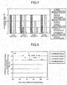
- FIG. 7 is a table indicating a determination result of the driving behavior prediction by the vehicle driving behavior predicting device 1 of this embodiment at the time of the entry into a plurality of intersections.
- FIG. 8 is a view illustrating prediction timing when it is correctly determined in the determination result in FIG. 7 .
- six templates with different cruising speeds were created by using the template converting method of this embodiment. Then, the decelerating behavior or the cruising behavior of the forward vehicle was predicted by using the created templates at four intersections A to D.
- the forward vehicle was allowed to travel at the cruising speeds of the created six templates and exhibit the decelerating behavior and the cruising behavior three times. That is to say, the driving behavior prediction was performed six times at each intersection (seven times at the intersection B) and the driving behavior prediction was performed a total of 25 times.
- FIG. 7 is a graph indicating the determination results of the verification experiment.
- the determination results at the intersections A to D are represented along the horizontal axis from left in this order.
- the number of times of correct determination at the time of the cruise of the forward vehicle, the number of times of erroneous determination at the time of the cruise of the forward vehicle, the number of times of the correct determination at the time of the deceleration of the forward vehicle, and the number of times of the erroneous determination at the time of the deceleration of the forward vehicle are indicated by a bar graph from left in this order. Meanwhile, "0" is indicated in the table for an item, the number of times of which is 0. As illustrated in FIG.
- FIG. 8 is the view illustrating the prediction timing when it is correctly determined in the verification experiment.
- the distance from the intersection when the prediction result of the driving behavior is output and the cruising speed of each template are represented along the horizontal axis and the vertical axis, respectively, in FIG. 8 . That is to say, it is illustrated that the prediction result is output more quickly as it is plotted on a left side in the drawing and that this is output more slowly as it is plotted on a right side. As illustrated in FIG. 8 , the higher the speed during the cruise, the quicker the prediction is executed. An average of a point at which the prediction is completed was 62 m before the intersection.
- the driving behavior includes the decelerating behavior of the vehicle and the template converting unit 144 converts the positional information indicating the distance from the prediction target point, the speed information, and the acceleration information at the accelerator-off point and the brake-on point of the decelerating behavior on the reference template according to the entry speed into the prediction section.
- the accelerator-off point and the brake-on point of the decelerating behavior are the feature information changing depending on the entry speed of the vehicle, so that it becomes possible to appropriately change the template according to the traveling state of the vehicle and to predict the driving behavior with high accuracy by changing them.
- the template converting unit 144 converts the speed information at the accelerator-off point A such that this is decreased according to the entry speed and converts the positional information at the accelerator-off point A such that this approaches the prediction target point O as the entry speed of the vehicle into the prediction section becomes lower to move the accelerator-off point A to the accelerator-off point C in the reference template indicating the transition of the speed information (speed template 151).
- the speed information and the positional information at the brake-on point B are converted and the brake-on point B is moved to the brake-on point D based on the change amounts of the speed information and the positional information between the accelerator-off point A and the brake-on point B before the conversion and the speed information and the positional information at the converted accelerator-off point C.
- This configuration makes it possible to convert the template such that this approaches an actual speed transition of the vehicle at the time of the deceleration, and the accuracy of the prediction of the driving behavior may be further improved.
- the template converting unit 144 converts the positional information at the accelerator-off point E such that this approaches the prediction target point O2 as the entry speed of the vehicle into the prediction section becomes lower to move the accelerator-off point E to the accelerator-off point G in the reference template indicating the transition of the acceleration information (acceleration template 152).
- the acceleration information and the positional information at the brake-on point F are converted and the brake-on point F is moved to the brake-on point H based on the change amounts of the acceleration information and the positional information between the accelerator-off point E and the brake-on point F before the conversion, the acceleration information at the accelerator-off point E, and the positional information at the converted accelerator-off point G.
- This configuration makes it possible to convert the template such that this approaches an actual acceleration transition of the vehicle at the time of the deceleration, and the accuracy of the prediction of the driving behavior may be further improved.
- the driving behavior predicting process described in the embodiment may also be applied to a case in which the driving behavior of the own vehicle is predicted.
- the template converting unit 144 calculates the entry speed of the own vehicle from the speed information of the vehicle 100 (own vehicle) obtained by the vehicle state detecting unit 110 and converts the speed template 151 and the acceleration template 152 based on the calculated entry speed of the own vehicle, for example.
- the driving behavior predicting unit 145 predicts the driving behavior of the own vehicle by using the speed template 151 and the acceleration template 152 converted based on the entry speed of the own vehicle.
- the assistance providing unit 161 may also provide the driving assistance appropriate for each situation in consideration of both the prediction results of the driving behaviors of the forward vehicle and the own vehicle input from the driving behavior predicting unit 145.
- the driving behavior may also be another vehicle behavior such as accelerating behavior and non-accelerating behavior of the vehicle 100 or the forward vehicle, for example.
- the assistance providing unit 161 may also provide the driving assistance appropriate for each situation based on the prediction result in which the driving behavior of the forward vehicle or the own vehicle is predicted as the accelerating behavior or the non-accelerating behavior.
- the driving behavior predicting process is performed by using both the speed template 151 and the acceleration template in the above-described embodiment, it is also possible to use only one of them.
- the template regarding the traveling state information other than the speed and the acceleration may also be used.
- the configuration in which the speed template 151 and the acceleration template 152 are stored in the driving behavior database 150 in the vehicle 100 is illustrated in the above-described embodiment, it may also be configured that they are externally obtained by using a communication device and the like.
- the information regarding the accelerator-off point and the brake-on point is extracted as the feature information of the speed template 151 and the acceleration template 152 depending on the entry speed of the vehicle into the prediction section, the information is converted according to the entry speed, and according to this, the speed template 151 and the acceleration template 152 are converted is illustrated in the above-described embodiment, another feature information may also be converted.
Description
- The present invention relates to a vehicle driving behavior predicting device.
- It is conventionally known that a driving assistance system which provides driving assistance to a driver of a vehicle predicts a feature driving behavior of the vehicle and provides the driving assistance based on the predicted driving behavior. Patent Literature 1 discloses the technology to estimate the driving behavior at a target point by storing a template indicating a typical driving behavior in a certain section before the target point of the driving assistance and comparing actual driving data with the template, for example, as such vehicle driving behavior predicting device.
-
US 2008/120025 A1 according to the preamble of claim 1, relates to a driving behavior prediction method and apparatus.US 200/167820 A1 relates to a system for predicting driver behavior.JP 2010 221962 A WO 2006/130146 A1 relates to motor vehicle operating data collection and analysis. - Patent Literature 1: Japanese Patent Application Laid-open No.
2010-221962 - However, when the template is used for predicting the driving behavior as in Patent Literature 1, the typical driving behavior indicated by the template differs according to a traveling state of the vehicle such as a traveling speed, for example. Therefore, it is required to prepare various templates according to the traveling states of the vehicle for improving prediction accuracy of the driving behavior. The increased number of templates requires a large capacity of storage means for storing the templates and this might increase a manufacturing cost.
- The present invention is achieved in consideration of the above and an object thereof is to provide a vehicle driving behavior predicting device capable of minimizing a storage capacity for storing a template while maintaining sufficient prediction accuracy of a driving behavior of a vehicle by using the template. Solution to Problem
- In order to solve the above-described problem, a vehicle behavior predicting device according to the present invention is a vehicle driving behavior predicting device configured to predict a vehicle behavior at a prediction target point based on traveling state information indicating a traveling state of a vehicle, the device provided with storage means which stores a template including feature information indicating a typical transition of the traveling state information for each vehicle behavior in a predetermined prediction section to the prediction target point, converting means which converts at least a part of the feature information in the template based on an entry speed of the vehicle into the prediction section, and predicting means which predicts the vehicle behavior of the vehicle at the prediction target point by comparing the template converted by the converting means with current traveling state information of the vehicle.
- In the above-described vehicle behavior predicting device, it is preferable that the vehicle behavior includes a decelerating behavior of the vehicle, and the feature information converted by the converting means includes positional information indicating a distance from the prediction target point and the traveling state information at an accelerator-off point and a brake-on point of the decelerating behavior.
- In the above-described vehicle behavior predicting device, it is preferable that the traveling state information includes speed information of the vehicle, the converting means converts the speed information at the accelerator-off point so as to be decreased according to the entry speed and converts the positional information at the accelerator-off point so as to approach the prediction target point as the entry speed of the vehicle into the prediction section becomes lower, and converts the speed information and the positional information at the brake-on point based on change amounts of the speed information and the positional information between the accelerator-off point and the brake-on point before conversion and the speed information and the positional information at the converted accelerator-off point.
- In the above-described vehicle behavior predicting device, it is preferable that the traveling state information includes acceleration information of the vehicle, the converting means converts the positional information at the accelerator-off point so as to approach the prediction target point as the entry speed of the vehicle into the prediction section becomes lower, and converts the acceleration information and the positional information at the brake-on point based on change amounts of the acceleration information and the positional information between the accelerator-off point and the brake-on point before the conversion, the acceleration information at the accelerator-off point, and the positional information at the converted accelerator-off point.
- The vehicle driving behavior predicting device according to the present invention has an effect of minimizing the storage capacity for storing the template while maintaining the sufficient prediction accuracy of the driving behavior of the vehicle by using the template. Brief Description of Drawings
-
-
FIG. 1 is a block diagram illustrating an example of a configuration of a driving assistance system to which a vehicle driving behavior predicting device according to this embodiment is applied. -
FIG. 2 is a view illustrating an example of a speed template stored in a driving behavior database. -
FIG. 3 is a view illustrating an example of an acceleration template stored in the driving behavior database. -
FIG. 4 is a schematic diagram for illustrating an example of a method of converting the speed template by a template converting unit. -
FIG. 5 is a schematic diagram for illustrating an example of a method of converting the acceleration template by the template converting unit. -
FIG. 6 is a flowchart illustrating a vehicle driving behavior predicting process performed by the vehicle driving behavior predicting device of this embodiment. -
FIG. 7 is a table illustrating a determination result of vehicle behavior prediction by the vehicle driving behavior predicting device of this embodiment at the time of entry into a plurality of intersections. -
FIG. 8 is a view illustrating prediction timing at the time of correct determination in the determination result inFIG. 7 . - An embodiment of a vehicle driving behavior predicting device according to the present invention is hereinafter described with reference to the drawings. Meanwhile, in the following drawings, the same reference numeral is assigned to the same or corresponding part and the description thereof is not repeated.
- A configuration of the vehicle driving behavior predicting device according to the embodiment of the present invention is described with reference to
FIG. 1. FIG. 1 is a block diagram illustrating an example of a configuration of a driving assistance system to which the vehicle driving behavior predicting device according to this embodiment is applied. - As illustrated in
FIG. 1 , a vehicle driving behavior predicting device 1 according to this embodiment is applied to adriving assistance system 10 mounted on avehicle 100 as an own vehicle. - The
vehicle 100 is provided with any one of an engine, a motor and the like as a drive source for travel for allowing a rotary drive of a drive wheel. Thevehicle 100 may be the vehicle of any type such as a hybrid vehicle (HV) provided with both the engine and the motor, a conventional vehicle provided with the engine but without the motor, and an electric vehicle (EV) provided with the motor but without the engine. - The
driving assistance system 10 is roughly provided with a vehiclestate detecting unit 110, a travelingenvironment detecting unit 120, a forward vehicleinformation obtaining unit 130, anonboard controller 140, a driving behavior database 150 (storage means), and adriving assistance controller 160. - The
driving assistance system 10 predicts a driving behavior of a vehicle being a prediction target at a predetermined prediction target point (such as an intersection) based on traveling state information indicating a traveling state of the vehicle being the prediction target. This may provide driving assistance information according to the predicted driving behavior to a driver of theown vehicle 100. The vehicle driving behavior predicting device 1 according to this embodiment is a component regarding a prediction of the driving behavior in thedriving assistance system 10 and specifically relates to theonboard controller 140 and thedriving behavior database 150 out of components of the above-describeddriving assistance system 10. - Meanwhile, in this embodiment, a forward vehicle traveling in front of the
vehicle 100 is the vehicle being the prediction target. In this embodiment, the driving behavior to be predicted includes a decelerating behavior and a non-decelerating behavior such as cruise travel of the forward vehicle at the prediction target point such as the intersection, a crosswalk point, a T-junction, and a point in front of a store entrance. In the following description, the prediction target point is also referred to as the "intersection" being an example thereof. Each element of thedriving assistance system 10 and the vehicle driving behavior predicting device 1 is hereinafter individually described. - The vehicle
state detecting unit 110 detects the traveling state of the own vehicle (vehicle 100) out of the traveling state information. The vehiclestate detecting unit 110 is provided with avehicle speed sensor 111 which detects a traveling speed of thevehicle 100, anacceleration sensor 112 which detects acceleration of thevehicle 100 and the like, for example. Thevehicle speed sensor 111 and theacceleration sensor 112 are electrically connected to the onboard controller (ECU) 140 in which detection results of various sensors and the like are summarized through an onboard network such as a CAN (control area network), for example. Thevehicle speed sensor 111 detects a wheel rotational speed and outputs a signal according to the detected rotational speed to theonboard controller 140. Theacceleration sensor 112 detects the acceleration of thevehicle 100 and outputs a signal according to the detected acceleration to theonboard controller 140. - The traveling
environment detecting unit 120 detects a traveling position or the traveling environment of the own vehicle or the forward vehicle out of the traveling state information. The travelingenvironment detecting unit 120 is provided with aGPS 121 and the like which receives a satellite signal to detect an absolute position, that is to say, latitude and longitude of thevehicle 100 or the forward vehicle based on the received satellite signal, for example. TheGPS 121 detects the latitude and longitude of thevehicle 100 or the forward vehicle changing according to movement of thevehicle 100 or the forward vehicle, in other words, the latitude and longitude of each point at which thevehicle 100 or the forward vehicle travels and outputs latitude/longitude information indicating a detection result to theonboard controller 140. - The forward vehicle
information obtaining unit 130 obtains the information indicating the traveling state and the like of the forward vehicle out of the traveling state information. The forward vehicle includes not only one vehicle traveling right in front of thevehicle 100 traveling in front of thevehicle 100 in a traveling direction but also a plurality of vehicles traveling in front of thevehicle 100 in the traveling direction. The forward vehicleinformation obtaining unit 130 is provided with amillimeter wave radar 131 which detects presence of the forward vehicle traveling in front of thevehicle 100 in the traveling direction by using an electric wave in a millimeter waveband and anonboard communicator 132 which performs inter-vehicle communication with the vehicle traveling around thevehicle 100 and road-to-vehicle communication with a roadside communicator located on a roadside. When themillimeter wave radar 131 detects the presence of the forward vehicle traveling in front of thevehicle 100 in the traveling direction, this outputs a signal indicating a detection result to theonboard controller 140. Theonboard communicator 132 obtains the information indicating the traveling state such as the traveling speed or the acceleration of the forward vehicle through the inter-vehicle communication with the forward vehicle traveling in front of thevehicle 100 in the traveling direction, for example. Theonboard communicator 132 outputs the obtained information to theonboard controller 140. - In this embodiment, detecting means includes the vehicle
state detecting unit 110, the travelingenvironment detecting unit 120, and the forward vehicleinformation obtaining unit 130. The detecting means detects the traveling state information of the vehicle (including the own vehicle and the forward vehicle). - The
onboard controller 140 controls each unit of thedriving assistance system 10 such as thedriving assistance controller 160 based on various pieces of traveling state information input from the detecting means. Theonboard controller 140 is provided with a system controller 141, a travelingenvironment specifying unit 142, atemplate selecting unit 143, a template converting unit 144 (converting means), and a driving behavior predicting unit 145 (predicting means). - When detection results of driving operation elements are input from the vehicle
state detecting unit 110, the system controller 141 controls various onboard devices based on the detection results. Specifically, the system controller 141 controls the various onboard devices such as the engine, a brake, a turn-signal lamp, and a steering wheel based on the detection results of thevehicle speed sensor 111 and theacceleration sensor 112 and the detection results of an accelerator sensor, a brake sensor, a steering angle sensor and the like input from the vehiclestate detecting unit 110. According to this, when the detection result of the accelerator sensor and the like changes by depression of an accelerator pedal by the driver, for example, a control amount of the engine is calculated according to the detection result and the engine is controlled according to a calculated result. - The traveling
environment specifying unit 142 specifies the traveling environment of thevehicle 100 or the forward vehicle based on the information such as the latitude/longitude information of thevehicle 100 or the forward vehicle input from the travelingenvironment detecting unit 120. The traveling environment includes an element which affects a vehicle behavior such as a road type such as the intersection and a curve, a shape, a road line shape, a road width, a curvature, a gradient and the like. When the travelingenvironment specifying unit 142 specifies the traveling environment of thevehicle 100 or the forward vehicle, this outputs the information to thetemplate selecting unit 143. - The
template selecting unit 143 selects a template associated with a prediction section in which the driving behavior of the forward vehicle is predicted based on the traveling environment specified by the travelingenvironment specifying unit 142 and obtains the same from the drivingbehavior database 150. Herein, a predetermined section to the prediction target point (such as the intersection) in front of the vehicle may be set as the prediction section. Thetemplate selecting unit 143 may detect the prediction target point and the prediction section located in front of the vehicle on a traveling road based on the traveling environment specified by the travelingenvironment specifying unit 142. The term "template" used in the embodiment is intended to mean a group of information including feature information indicating a typical transition of the traveling state information for each driving behavior and indicates, in other words, the transition of the traveling state information of the vehicle corresponding to the driving behavior being the prediction target in a predetermined prediction section to the prediction target point. Aspeed template 151 and anacceleration template 152 indicating the transitions of the speed and the acceleration of the traveling state information are stored in thedriving behavior database 150. - Herein, the
speed template 151 and theacceleration template 152 stored in thevehicle behavior database 150 are described with reference toFIGS. 2 and3 .FIG. 2 is a view illustrating an example of thespeed template 151 stored in the vehicle behavior database. A distance (m) from the intersection being the prediction target point and speed information (km/h) are represented along a horizontal axis and a vertical axis, respectively, of thespeed template 151 inFIG. 2 . - The
speed template 151 includes the typical transition of the speed information of the vehicle according to the distance to the prediction target point in the predetermined prediction section before the prediction target point. Thespeed template 151 includes individual speed transition patterns in two different driving behaviors: the driving behavior at the time of deceleration toward the prediction target point (decelerating behavior) and the driving behavior at the time of passage of the prediction target point at a cruising speed without deceleration (cruising behavior). The cruising behavior is an example of the above-described non-decelerating behavior. Herein, the cruising behavior is the traveling state in which the speed does not monotonically increase, does not monotonically decrease, or is not at 0 (km/h) with variation in speed in a certain distance section or time section within a predetermined range σ, and it may be defined that the cruising speed is an average speed in the cruising behavior. The predetermined range σ of the variation may be obtained from the speed information at the time of steady driving by the driver, for example. - It is possible to create the speed transition pattern of the decelerating behavior by averaging data of the speed transition in the prediction section when the
vehicle 100 or the forward vehicle turns right or left, for example. It is possible to create the speed transition pattern of the cruising behavior by averaging data of the speed transition in the prediction section when thevehicle 100 or the forward vehicle goes straight, for example. As illustrated inFIG. 2 , an average value and a 95% confidence interval of the speed transition of the decelerating behavior and an average value and a 95% confidence interval of the speed transition of the cruising behavior are recorded in thespeed template 151. - As illustrated in
FIG. 2 , in thespeed template 151, the speed transition is substantially constant such that the speed variation falls within a certain range based on a predetermined cruising speed at the time of the cruising behavior. In the decelerating behavior, although the speed is substantially the same as that of the cruising behavior just after an entry into the prediction section (-100 m inFIG. 2 ), the speed gradually decreases as the distance to the prediction target point becomes shorter. -
FIG. 3 is a view illustrating an example of theacceleration template 152 stored in the vehicle behavior database. The distance (m) from the intersection being the prediction target point and the acceleration information (m/s^2) are represented along a horizontal axis and a vertical axis, respectively, of theacceleration template 152 inFIG. 3 . Theacceleration template 152 includes the typical transition of the acceleration information of the vehicle according to the distance to the prediction target point in the predetermined prediction section before the prediction target point. Theacceleration template 152, as well as thespeed template 151, includes individual acceleration transition patterns in the two different driving behaviors: the decelerating behavior and the cruising behavior. It is possible to create the acceleration transition patterns, as well as the speed transition patterns, by averaging data of the acceleration transition in the prediction section of thevehicle 100 or the forward vehicle. As illustrated inFIG. 3 , an average value and a 95% confidence interval of the acceleration transition of the decelerating behavior and an average value and a 95% confidence interval of the acceleration transition of the cruising behavior are recorded in theacceleration template 152. - As illustrated in
FIG. 3 , in theacceleration template 152, the acceleration transition is substantially constant such that acceleration variation falls within a certain range based on the acceleration of 0 in a case of the cruising behavior. In the decelerating behavior, although the acceleration is substantially 0 as in the cruising behavior just after the entry into the prediction section, the acceleration gradually increases in a negative direction, that is to say, the deceleration increases as the distance to the prediction target point becomes shorter. - In this embodiment, a set of the
speed template 151 and theacceleration template 152 created based on the speed and acceleration patterns in the cruising behavior and the decelerating behavior at the time of the entry into the prediction section at a certain cruising speed are associated with a certain prediction target point. That is to say, when it is specified that thevehicle 100 or the forward vehicle approaches a certain prediction target point, thetemplate selecting unit 143 always selects the same template from the drivingbehavior database 150 regardless of an entry speed even when the entry speed into the prediction section is different from the cruising speed of the template. Thetemplate selecting unit 143 outputs the selectedspeed template 151 and theacceleration template 152 to thetemplate converting unit 144. - With reference to
FIG. 1 again, thetemplate converting unit 144 converts thespeed template 151 and theacceleration template 152 selected by thetemplate selecting unit 143 according to the traveling state (the entry speed into the prediction section in this embodiment) of the forward vehicle being the target vehicle. In other words, thetemplate converting unit 144 converts thespeed template 151 and theacceleration template 152 selected by thetemplate selecting unit 143 to a form indicating the transition of the speed or the acceleration from the entry speed to a case in which the driving behavior being the prediction target is exhibited. The entry speed may be an average value of the speed in the predetermined section before the forward vehicle enters the prediction section or the vehicle speed when this enters the prediction section. The entry speed may be calculated from the speed information of the forward vehicle obtained by the forward vehicleinformation obtaining unit 130. - In more detail, the
template converting unit 144 converts positional information indicating the distance from the prediction target point and the speed information at an accelerator-off point and a brake-on point out of the feature information included in thespeed template 151 according to the entry speed into the prediction section, thereby changing the speed transition pattern of thespeed template 151 to an appropriate form according to the entry speed. Thetemplate converting unit 144 converts the positional information indicating the distance from the prediction target point and the acceleration information at the accelerator-off point and the brake-on point out of the feature information included in theacceleration template 152 according to the entry speed into the prediction section, thereby changing theacceleration template 152 to an appropriate form according to the entry speed. - Herein, a method of converting the
speed template 151 and theacceleration template 152 by thetemplate converting unit 144 is described with reference toFIGS. 4 and 5. FIG. 4 is a schematic diagram for illustrating an example of the method of converting thespeed template 151 by thetemplate converting unit 144 andFIG. 5 is a schematic diagram for illustrating an example of the method of converting theacceleration template 152 by thetemplate converting unit 144. The vertical axis and the horizontal axis inFIGS. 4 and 5 are the same as those inFIGS. 2 and3 . InFIG. 4 , the speed transition before conversion is indicated by a solid line and the speed transition after the conversion is indicated by a dotted line. Similarly, inFIG. 5 , the acceleration transition before the conversion is indicated by a solid line and the acceleration transition after the conversion is indicated by a dotted line. - An example of converting the
speed template 151 is described with reference toFIG. 4 . In the speed transition pattern of the decelerating behavior in thespeed template 151, the feature information regarding the method of converting includes: (1) the positional information and the speed information at an accelerator-off point A where the driver turns off the accelerator, (2) required time while the accelerator is turned off, (3) the positional information and the speed information at a brake-on point B where the driver turns on the brake, and (4) a minimum speed at a deceleration target point (prediction target point) O, as illustrated inFIG. 4 . The speed undergoes a transition so as to reach the deceleration target point O with smooth deceleration through the accelerator-off point A and the brake-on point B. - Herein, a case in which the entry speed of the vehicle into the prediction section becomes lower than the cruising speed of the
speed template 151 is considered. In this case, a situation in which accelerator-off operation by the driver is delayed and the accelerator-off point A approaches the deceleration target point (intersection) O is considered. Brake-on operation is also delayed according to this and the brake-on point B also approaches the deceleration target point O. That is to say, it may be considered that there is a correlation among the entry speed of the vehicle into the prediction section, the accelerator-off point A, and the brake-on point B. On the other hand, the required time from the accelerator-off operation to the brake-on operation does not depend on the entry speed of the vehicle. In the decelerating behavior, the minimum speed at a final deceleration target point O and a position at which the state is realized (the distance from the intersection = 0) remain unchanged regardless of the entry speed of the vehicle. - Therefore, in this embodiment, out of the feature information regarding the speed transition pattern of the
speed template 151, the feature information depending on the entry speed into the prediction section (accelerator-off point and brake-on point) are converted according to the entry speed and the feature information independent from the entry speed (accelerator-off time and deceleration target point) are fixed to be used. Specifically, a motion amount (in a direction of the horizontal axis inFIG. 4 ) of the positional information at the accelerator-off point A is first calculated according to the entry speed of the vehicle. It is possible to calculate the motion amount of the positional information by using a function derived by a learning process by using past travel data, for example. Input and output of the function are the entry speed and the motion amount of the positional information at the accelerator-off point A, respectively. Next, a motion amount (in a direction of the vertical axis inFIG. 4 ) of the speed information at the accelerator-off point A is obtained based on the entry speed. It is possible to calculate the motion amount of the speed information by multiplying a predetermined coefficient by difference between the speed information at the accelerator-off point A before the conversion and the entry speed, for example. According to this, the motion amount of the positional information and the motion amount of the speed information at the accelerator-off point A are calculated and the accelerator-off point may be moved. In the example inFIG. 4 , the entry speed is lower than the cruising speed, so that this is moved to an accelerator-off point C with a shorter distance from the intersection and a lower speed than those at the accelerator-off point A. - Next, a line segment connecting the accelerator-off point A and the brake-on point B before the conversion is moved in parallel such that this passes through the accelerator-off point C after the conversion. Since the required time from the accelerator-off operation to the brake-on operation is constant regardless of the entry speed, so that a length of the line segment is increased or decreased according to the entry speed. In the example in
FIG. 4 , the entry speed is lower than the cruising speed, so that a length L2 of the line segment is made shorter than a length L1 of the line segment between A and B. Furthermore, a brake-on point D after the conversion is plotted at an end on a side opposite to the accelerator-off point C of the line segment. - After the accelerator-off point C and the brake-on point D are determined in this manner, it is possible to form the speed transition pattern of the decelerating behavior after the conversion as indicated by the dotted line in
FIG. 4 by using a well-known interpolating method such as linear interpolation and secondary interpolation among three points of these points and the deceleration target point O. - In the speed transition pattern of the cruising behavior in the
speed template 151, it is possible to form the speed transition pattern of the cruising behavior after the conversion by moving the average value of the cruising speed in parallel in the direction of the vertical axis inFIG. 4 according to the entry speed, for example. - An example of converting the
acceleration template 152 is described with reference toFIG. 5 . In the acceleration transition pattern of the decelerating behavior in theacceleration template 152, the feature information regarding the method of converting includes: (1) the acceleration information and the positional information at an accelerator-off point E, (2) declination of the acceleration while the accelerator is turned off, (3) the acceleration information and the positional information at a brake-on point F, and (4) minimum acceleration at a deceleration target point (prediction target point) O2, as illustrated inFIG. 5 . The acceleration undergoes a transition so as to reach the deceleration target point O2 with a smooth increase in the acceleration in the negative direction through the accelerator-off point E and the brake-on point F. - Herein, a case in which the entry speed of the vehicle into the prediction section becomes lower than the cruising speed of the
acceleration template 152 is considered. In this case, a situation in which the accelerator-off operation by the driver is delayed and the accelerator-off point E approaches the deceleration target point O2 is considered. The brake-on operation is also delayed according to this and the brake-on point F also approaches the deceleration target point O2. That is to say, it may be considered that there is a correlation between the entry speed of the vehicle and the positional information of the accelerator-off point E and the brake-on point F. - On the other hand, the acceleration is substantially constant when the accelerator is turned off, so that the acceleration information at the accelerator-off point E does not depend on the entry speed. After the accelerator is turned off, predetermined deceleration such as engine braking occurs, so that the acceleration changes with a substantially constant pattern without depending on the entry speed. Since there is repeatability in the decelerating behavior of the driver, so that magnitude of the minimum acceleration at the deceleration target point O2 and the position at which the state is realized (the distance from the intersection = 0) are constant regardless of the entry speed of the vehicle.
- Therefore, in this embodiment, out of the feature information regarding the acceleration transition pattern of the
acceleration template 152, the feature information depending on the entry speed into the prediction section (accelerator-off point and brake-on point) are converted according to the entry speed and the feature information independent from the entry speed (the declination of the acceleration while the accelerator is turned off and the deceleration target point) are fixed to be used. First, a motion amount (in a direction of the horizontal axis inFIG. 5 ) of the positional information at the accelerator-off point E is calculated according to the entry speed of the vehicle. It is possible to use a function derived by the learning process by using the past travel data, for example, as at the accelerator-off point A inFIG. 4 for calculating the motion amount of the positional information. Input and output of the function are the entry speed and the motion amount of the positional information at the accelerator-off point E, respectively. Meanwhile, the acceleration is substantially constant when the accelerator is turned off, so that a motion amount of the acceleration information from the accelerator-off point E (in a direction of the vertical axis inFIG. 5 ) is set to 0. According to this, it is possible to move the accelerator-off point E in the horizontal direction. In the example inFIG. 5 , the entry speed is lower than the cruising speed, so that this is moved in parallel to an accelerator-off point G with a shorter distance from the intersection than that of the accelerator-off point E. - Next, a line segment connecting the accelerator-off point E and the brake-on point F before the conversion is moved in parallel such that this passes through the accelerator-off point G after the conversion. A brake-on point H after the conversion is plotted at an end on a side opposite to the accelerator-off point G of the line segment.
- After the accelerator-off point G and the brake-on point H are determined in this manner, it is possible to form the acceleration transition pattern of the decelerating behavior after the conversion as indicated by the dotted line in
FIG. 5 by using the well-known interpolating method such as the linear interpolation and the secondary interpolation among three points of these points and the deceleration target point O2. - In the acceleration transition pattern of the cruising behavior in the
acceleration template 152, the average value of the acceleration transition does not depend on the entry speed of the vehicle and is maintained in the vicinity of the acceleration of 0, so that the same one is always used. - Meanwhile, in this embodiment, the
speed template 151 and theacceleration template 152 stored in thedriving behavior database 150 are also referred to as "reference templates", and thespeed template 151 and theacceleration template 152 converted by thetemplate converting unit 144 are also referred to as "converted templates". - With reference to
FIG. 1 again, the drivingbehavior predicting unit 145 compares thespeed template 151 and theacceleration template 152 converted by thetemplate converting unit 144 with time-series change in the traveling state information of the vehicle at present time detected by the detecting means (current transition of speed information and acceleration information of the vehicle) to predict the driving behavior at the prediction target point. When the drivingbehavior predicting unit 145 recognizes that there is the forward vehicle in front of thevehicle 100 in the traveling direction based on the information input from the forward vehicleinformation obtaining unit 130, this predicts the driving behavior of the forward vehicle. The drivingbehavior predicting unit 145 predicts whether the decelerating behavior occurs, for example, as the driving behavior of the forward vehicle. The drivingbehavior predicting unit 145 may determine that the decelerating behavior of the forward vehicle is uncertain when this cannot predict whether the decelerating behavior of the forward vehicle occurs or not with high probability. - The driving
assistance controller 160 performs control regarding various types of driving assistance based on the prediction result by the drivingbehavior predicting unit 145. The drivingassistance controller 160 is provided with anassistance providing unit 161, aspeech unit 162, and adisplay unit 163. - When the prediction result of the driving behavior of the forward vehicle is input from the driving
behavior predicting unit 145, theassistance providing unit 161 obtains control amounts of various control devices controlled by the above-described system controller 141, for example, based on the prediction result and outputs the obtained control amounts to the system controller 141. According to this, when the prediction result of the drivingbehavior predicting unit 145 indicates the occurrence of the decelerating behavior of the forward vehicle, for example, this turns off the engine or turns on the brake at the timing at which the forward vehicle decelerates or before the timing. When thevehicle 100 is the hybrid vehicle, theassistance providing unit 161 executes brake regeneration at the timing at which the forward vehicle decelerates or before the timing. Theassistance providing unit 161 generates speech data or image data for speech guidance or image guidance about the decelerating behavior to be performed by the forward vehicle, for example, and outputs the generated speech data or image data to thespeech unit 162 and thedisplay unit 163 at the timing at which the forward vehicle decelerates or before the timing. According to this, the guidance to urge the driver of thevehicle 100 to decelerate thevehicle 100 is provided when the forward vehicle decelerates or before the deceleration is started through thespeech unit 162 and thedisplay unit 163. - On the other hand, when the prediction result of the driving
behavior predicting unit 145 indicates that the decelerating behavior of the forward vehicle does not occur, that is to say, the driving behavior of the forward vehicle is the cruising behavior (non-decelerating behavior), theassistance providing unit 161 does not execute deceleration assistance through the system controller 141, thespeech unit 162, and thedisplay unit 163. At that time, theassistance providing unit 161 may notify the driver that the forward vehicle does not perform the decelerating behavior through thespeech unit 162 and thedisplay unit 163, for example. Similarly, theassistance providing unit 161 does not execute the deceleration assistance through the system controller 141, thespeech unit 162, and thedisplay unit 163 also when a determination result that the driving behavior of the forward vehicle is uncertain is input from the drivingbehavior predicting unit 145. - Each function of the
onboard controller 140 and theassistance providing unit 161 of the drivingassistance controller 160 is realized by an electronic control unit (ECU) mounted on thevehicle 100. The ECU is formed as an electronic circuit mainly formed of a well-known microcomputer including a CPU, a ROM, a RAM, and an interface, for example. - Next, operation of the vehicle driving behavior predicting device 1 according to this embodiment is described with reference to
FIG. 6. FIG. 6 is a flowchart illustrating a vehicle driving behavior predicting process performed by the vehicle driving behavior predicting device 1 of this embodiment. - First, when the traveling environment of the
vehicle 100 is specified by the travelingenvironment specifying unit 142 and an approach to the predetermined prediction section before the prediction target point is detected (S01), thetemplate selecting unit 143 obtains thespeed template 151 and theacceleration template 152 associated with the prediction section from the driving behavior database 150 (S02). - Next, speed information (v1 to vn) of the forward vehicle in a predetermined section before the entry into the prediction section is detected by the traveling environment specifying unit 142 (S03) and an average speed v of the speed information is defined as the entry speed of the forward vehicle into the prediction section (S04). Meanwhile, the predetermined section in which the speeds v1 to vn are detected may be an optional distance section or time section before the prediction section.
- The
template converting unit 144 converts thespeed template 151 and theacceleration template 152 obtained at step S02 according to the entry speed v of the forward vehicle (S05). The method described with reference toFIGS. 4 and 5 may be used, for example, as the method of converting the template. Thetemplate converting unit 144 may change thespeed template 151 and theacceleration template 152 such that they conform to the entry speed v of the forward vehicle by extracting to change the feature information changing depending on the entry speed v out of the feature information of the transition patterns of thespeed template 151 and theacceleration template 152. - Then, the driving
behavior predicting unit 145 predicts the driving behavior of the forward vehicle by using thespeed template 151 and theacceleration template 152 converted at step S05 (S06). The drivingbehavior predicting unit 145 may predict whether the forward vehicle exhibits the decelerating behavior or the cruising behavior (non-decelerating behavior) at the prediction target position by comparing thespeed template 151 and theacceleration template 152 converted by thetemplate converting unit 144 with the time-series change in the speed and the acceleration of the forward vehicle detected by the detecting means. When the drivingbehavior predicting unit 145 outputs information of the prediction result to theassistance providing unit 161 of the drivingassistance controller 160, the process of this flow is finished. - Next, an effect of the vehicle driving behavior predicting device 1 according to this embodiment is described.
- The vehicle driving behavior predicting device 1 of this embodiment is configured to predict the driving behavior of the forward vehicle at the prediction target point based on the speed information or the acceleration information of the forward vehicle. The vehicle driving behavior predicting device 1 is provided with the driving
behavior database 150 which stores the reference templates (speed template 151 and acceleration template 152) indicating the transition of the speed information or the acceleration information of the vehicle corresponding to the driving behavior being the prediction target in the predetermined prediction section to the prediction target point, thetemplate converting unit 144 which converts the reference template to the converted template indicating the transition of the speed or the acceleration from the entry speed to a case in which the driving behavior being the prediction target is exhibited based on the entry speed of the forward vehicle into the prediction section, and the drivingbehavior predicting unit 145 which predicts the driving behavior of the forward vehicle at the prediction target point by comparing the converted template with the current transition of the speed information or acceleration information of the forward vehicle. - It becomes possible to convert a set of the
speed template 151 and theacceleration template 152 based on the entry speed to use for predicting the driving behavior by this configuration, so that it becomes not necessary to individually prepare the template according to the traveling state of the vehicle and a storage capacity for storing the template may be minimized. The template is converted based on the entry speed of the vehicle to be used for predicting the driving behavior, so that the prediction according to the traveling state of the vehicle becomes possible and sufficient accuracy of the prediction of the driving behavior may be maintained. - Herein, the prediction accuracy by the vehicle driving behavior predicting device 1 of this embodiment is further described with reference to
FIGS. 7 and 8. FIG. 7 is a table indicating a determination result of the driving behavior prediction by the vehicle driving behavior predicting device 1 of this embodiment at the time of the entry into a plurality of intersections.FIG. 8 is a view illustrating prediction timing when it is correctly determined in the determination result inFIG. 7 . In a verification experiment illustrated inFIGS. 7 and 8 , six templates with different cruising speeds were created by using the template converting method of this embodiment. Then, the decelerating behavior or the cruising behavior of the forward vehicle was predicted by using the created templates at four intersections A to D. The forward vehicle was allowed to travel at the cruising speeds of the created six templates and exhibit the decelerating behavior and the cruising behavior three times. That is to say, the driving behavior prediction was performed six times at each intersection (seven times at the intersection B) and the driving behavior prediction was performed a total of 25 times. -
FIG. 7 is a graph indicating the determination results of the verification experiment. The determination results at the intersections A to D are represented along the horizontal axis from left in this order. At each intersection, the number of times of correct determination at the time of the cruise of the forward vehicle, the number of times of erroneous determination at the time of the cruise of the forward vehicle, the number of times of the correct determination at the time of the deceleration of the forward vehicle, and the number of times of the erroneous determination at the time of the deceleration of the forward vehicle are indicated by a bar graph from left in this order. Meanwhile, "0" is indicated in the table for an item, the number of times of which is 0. As illustrated inFIG. 7 , at the intersections A and D, the determination was correct in all the templates for both the cruising behavior and the decelerating behavior. At the intersection B, all three decelerating behaviors were correctly determined but one of four cruising behaviors was erroneously determined. At the intersection C, all three cruising behaviors were correctly determined but one of three decelerating behaviors was erroneously determined. As a whole, 23 of the 25 times of prediction were correctly determined and an accuracy rate was 92%. In this manner, in the experiment result illustrated inFIG. 7 , it was proved that the sufficient accuracy of the prediction of the driving behavior may be maintained by the method of this embodiment to convert the template according to the entry speed of the vehicle. -
FIG. 8 is the view illustrating the prediction timing when it is correctly determined in the verification experiment. The distance from the intersection when the prediction result of the driving behavior is output and the cruising speed of each template are represented along the horizontal axis and the vertical axis, respectively, inFIG. 8 . That is to say, it is illustrated that the prediction result is output more quickly as it is plotted on a left side in the drawing and that this is output more slowly as it is plotted on a right side. As illustrated inFIG. 8 , the higher the speed during the cruise, the quicker the prediction is executed. An average of a point at which the prediction is completed was 62 m before the intersection. In the study heretofore, it is known that the driver becomes aware of the deceleration of the forward vehicle when the turn-signal lamp and the brake lamp of the forward vehicle are turned on and the timing at which the lamp is turned on is about 30 m before the intersection. Therefore, the experiment result illustrated inFIG. 8 proved that the driving behavior may be predicted quickly enough by the method of this embodiment in which the template is converted according to the entry speed of the vehicle. - In the vehicle driving behavior predicting device 1 of this embodiment, the driving behavior includes the decelerating behavior of the vehicle and the
template converting unit 144 converts the positional information indicating the distance from the prediction target point, the speed information, and the acceleration information at the accelerator-off point and the brake-on point of the decelerating behavior on the reference template according to the entry speed into the prediction section. - The accelerator-off point and the brake-on point of the decelerating behavior are the feature information changing depending on the entry speed of the vehicle, so that it becomes possible to appropriately change the template according to the traveling state of the vehicle and to predict the driving behavior with high accuracy by changing them.
- In the vehicle driving behavior predicting device 1 of this embodiment, the
template converting unit 144 converts the speed information at the accelerator-off point A such that this is decreased according to the entry speed and converts the positional information at the accelerator-off point A such that this approaches the prediction target point O as the entry speed of the vehicle into the prediction section becomes lower to move the accelerator-off point A to the accelerator-off point C in the reference template indicating the transition of the speed information (speed template 151). The speed information and the positional information at the brake-on point B are converted and the brake-on point B is moved to the brake-on point D based on the change amounts of the speed information and the positional information between the accelerator-off point A and the brake-on point B before the conversion and the speed information and the positional information at the converted accelerator-off point C. - This configuration makes it possible to convert the template such that this approaches an actual speed transition of the vehicle at the time of the deceleration, and the accuracy of the prediction of the driving behavior may be further improved.
- In the vehicle driving behavior predicting device 1 of this embodiment, the
template converting unit 144 converts the positional information at the accelerator-off point E such that this approaches the prediction target point O2 as the entry speed of the vehicle into the prediction section becomes lower to move the accelerator-off point E to the accelerator-off point G in the reference template indicating the transition of the acceleration information (acceleration template 152). The acceleration information and the positional information at the brake-on point F are converted and the brake-on point F is moved to the brake-on point H based on the change amounts of the acceleration information and the positional information between the accelerator-off point E and the brake-on point F before the conversion, the acceleration information at the accelerator-off point E, and the positional information at the converted accelerator-off point G. - This configuration makes it possible to convert the template such that this approaches an actual acceleration transition of the vehicle at the time of the deceleration, and the accuracy of the prediction of the driving behavior may be further improved.
- Although the embodiment of the present invention is described above, the above-described embodiment is presented as an example and it is not intended to limit the scope of the invention. The above-described embodiment may be carried out in various other modes and it is possible to omit, replace, and change this in various manners without departing from the gist of the invention. The above-described embodiment and variation thereof are included in the scope and the gist of the invention and are also included in the invention recited in claims and the equivalents thereof.
- Although the forward vehicle is described as an example of the target the driving behavior of which is predicted in the above-described embodiment, the driving behavior predicting process described in the embodiment may also be applied to a case in which the driving behavior of the own vehicle is predicted. In this case, the
template converting unit 144 calculates the entry speed of the own vehicle from the speed information of the vehicle 100 (own vehicle) obtained by the vehiclestate detecting unit 110 and converts thespeed template 151 and theacceleration template 152 based on the calculated entry speed of the own vehicle, for example. Then, the drivingbehavior predicting unit 145 predicts the driving behavior of the own vehicle by using thespeed template 151 and theacceleration template 152 converted based on the entry speed of the own vehicle. - The
assistance providing unit 161 may also provide the driving assistance appropriate for each situation in consideration of both the prediction results of the driving behaviors of the forward vehicle and the own vehicle input from the drivingbehavior predicting unit 145. The driving behavior may also be another vehicle behavior such as accelerating behavior and non-accelerating behavior of thevehicle 100 or the forward vehicle, for example. In this case, theassistance providing unit 161 may also provide the driving assistance appropriate for each situation based on the prediction result in which the driving behavior of the forward vehicle or the own vehicle is predicted as the accelerating behavior or the non-accelerating behavior. - Although the driving behavior predicting process is performed by using both the
speed template 151 and the acceleration template in the above-described embodiment, it is also possible to use only one of them. The template regarding the traveling state information other than the speed and the acceleration may also be used. - Although the configuration in which the
speed template 151 and theacceleration template 152 are stored in thedriving behavior database 150 in thevehicle 100 is illustrated in the above-described embodiment, it may also be configured that they are externally obtained by using a communication device and the like. - Although the configuration in which the information regarding the accelerator-off point and the brake-on point is extracted as the feature information of the
speed template 151 and theacceleration template 152 depending on the entry speed of the vehicle into the prediction section, the information is converted according to the entry speed, and according to this, thespeed template 151 and theacceleration template 152 are converted is illustrated in the above-described embodiment, another feature information may also be converted. -
- 1 vehicle driving behavior predicting device
- 100 vehicle
- 144 template converting unit (converting means)
- 145 driving behavior predicting unit (predicting means)
- 150 driving behavior database (storage means)
- 151 speed template
- 152 acceleration template
Claims (4)
- A vehicle driving behavior predicting device (1) configured to predict a driving behavior of a vehicle (100) at a prediction target point based on speed information or acceleration information of the vehicle (100), the device comprising:
a storage unit configured to store a reference template (151; 152) characterising in that said reference template (151; 152) is adapted to indicate a transition of the speed information or the acceleration information of the vehicle (100) corresponding to the driving behavior being a prediction target in a predetermined prediction section to the prediction target point; and said vehicle driving behavior predicting device (1) comprises further :a converting unit (144) configured to convert the reference template (151; 152) to a converted template indicating a transition of a speed or acceleration from an entry speed to a case in which the driving behavior being the prediction target is exhibited based on the entry speed of the vehicle (100) into the prediction section; anda predicting unit (145) configured to predict the driving behavior of the vehicle (100) at the prediction target point by comparing the converted template with a current transition of the speed information or the acceleration information of the vehicle (100). - The vehicle driving behavior predicting device (1) according to claim 1, wherein
the driving behavior includes a decelerating behavior, and
the converting unit (144) is configured to convert positional information indicating a distance from the prediction target point, the speed information, or the acceleration information at an accelerator-off point and a brake-on point of the decelerating behavior on the reference template (151; 152) according to the entry speed into the prediction section. - The vehicle driving behavior predicting device (1) according to claim 2, wherein
the converting unit (144) is configured to convert the speed information at the accelerator-off point so as to be decreased according to the entry speed and converts the positional information at the accelerator-off point so as to approach the prediction target point as the entry speed of the vehicle (100) into the prediction section becomes lower in the reference template (151) indicating the transition of the speed information, and
to convert the speed information and the positional information at the brake-on point based on change amounts of the speed information and the positional information between the accelerator-off point and the brake-on point before conversion and the speed information and the positional information at the converted accelerator-off point. - The vehicle driving behavior predicting device (1) according to claim 2 or 3, wherein
the converting unit (144) is configured to convert the positional information at the accelerator-off point so as to approach the prediction target point as the entry speed of the vehicle (100) into the prediction section becomes lower in the reference template (152) indicating the transition of the acceleration information, and
to convert the acceleration information and the positional information at the brake-on point based on change amounts of the acceleration information and the positional information between the accelerator-off point and the brake-on point before the conversion, the acceleration information at the accelerator-off point, and the positional information at the converted accelerator-off point.
Applications Claiming Priority (1)
| Application Number | Priority Date | Filing Date | Title |
|---|---|---|---|
| PCT/JP2012/073942 WO2014045355A1 (en) | 2012-09-19 | 2012-09-19 | Device for predicting vehicle driving behavior |
Publications (3)
| Publication Number | Publication Date |
|---|---|
| EP2899087A1 EP2899087A1 (en) | 2015-07-29 |
| EP2899087A4 EP2899087A4 (en) | 2017-04-26 |
| EP2899087B1 true EP2899087B1 (en) | 2018-09-12 |
Family
ID=50340714
Family Applications (1)
| Application Number | Title | Priority Date | Filing Date |
|---|---|---|---|
| EP12884749.8A Not-in-force EP2899087B1 (en) | 2012-09-19 | 2012-09-19 | Vehicle driving behavior predicting device |
Country Status (5)
| Country | Link |
|---|---|
| US (1) | US9428196B2 (en) |
| EP (1) | EP2899087B1 (en) |
| JP (1) | JP5874837B2 (en) |
| CN (1) | CN104640756B (en) |
| WO (1) | WO2014045355A1 (en) |
Families Citing this family (19)
| Publication number | Priority date | Publication date | Assignee | Title |
|---|---|---|---|---|
| US10002531B2 (en) * | 2014-12-10 | 2018-06-19 | Here Global B.V. | Method and apparatus for predicting driving behavior |
| DE102015005964A1 (en) * | 2015-05-08 | 2016-11-10 | Man Truck & Bus Ag | Method for controlling or controlling the damper force of adjustable dampers in motor vehicles, in particular in commercial vehicles |
| US9764741B2 (en) * | 2016-01-27 | 2017-09-19 | Delphi Technologies, Inc. | Operator skill scoring based on comparison to automated vehicle operation |
| CN108202745B (en) * | 2016-12-19 | 2020-10-02 | 法法汽车(中国)有限公司 | Method and system for predicting state of obstacle vehicle |
| JP6544348B2 (en) * | 2016-12-22 | 2019-07-17 | トヨタ自動車株式会社 | Vehicle driving support device |
| KR101901801B1 (en) | 2016-12-29 | 2018-09-27 | 현대자동차주식회사 | Hybrid vehicle and method of predicting driving pattern |
| US10259468B2 (en) * | 2017-06-15 | 2019-04-16 | Hitachi, Ltd. | Active vehicle performance tuning based on driver behavior |
| JP6550100B2 (en) * | 2017-06-29 | 2019-07-24 | 株式会社Subaru | Vehicle control apparatus and vehicle control method |
| JP7027054B2 (en) * | 2017-07-07 | 2022-03-01 | 株式会社東芝 | Information processing equipment, vehicles, information processing methods and programs |
| US11029693B2 (en) * | 2017-08-08 | 2021-06-08 | Tusimple, Inc. | Neural network based vehicle dynamics model |
| JP7001009B2 (en) * | 2018-07-11 | 2022-01-19 | トヨタ自動車株式会社 | Wind data estimator |
| JP2020066390A (en) * | 2018-10-26 | 2020-04-30 | 日立オートモティブシステムズ株式会社 | Driving assistance device |
| KR20210032617A (en) * | 2019-09-16 | 2021-03-25 | 현대자동차주식회사 | Apparatus for controlling behavior of autonomous vehicle and method thereof |
| CN110667597B (en) * | 2019-10-14 | 2021-07-23 | 吉林大学 | Driving style state identification method based on vehicle controller local area network data information |
| US11794731B2 (en) | 2020-08-12 | 2023-10-24 | Ford Global Technologies, Llc | Waypoint prediction for vehicle motion planning |
| US11618444B2 (en) | 2020-10-01 | 2023-04-04 | Argo AI, LLC | Methods and systems for autonomous vehicle inference of routes for actors exhibiting unrecognized behavior |
| US11358598B2 (en) | 2020-10-01 | 2022-06-14 | Argo AI, LLC | Methods and systems for performing outlet inference by an autonomous vehicle to determine feasible paths through an intersection |
| US11760388B2 (en) | 2021-02-19 | 2023-09-19 | Argo AI, LLC | Assessing present intentions of an actor perceived by an autonomous vehicle |
| CN117325875B (en) * | 2023-12-01 | 2024-02-02 | 北京航空航天大学 | Vehicle long-term speed prediction method based on individual driving characteristics |
Family Cites Families (9)
| Publication number | Priority date | Publication date | Assignee | Title |
|---|---|---|---|---|
| US9189895B2 (en) * | 2005-06-01 | 2015-11-17 | Allstate Insurance Company | Motor vehicle operating data collection and analysis |
| JP4797948B2 (en) * | 2006-11-22 | 2011-10-19 | 株式会社デンソー | Driving behavior estimation method and apparatus |
| US20080167820A1 (en) * | 2007-01-04 | 2008-07-10 | Kentaro Oguchi | System for predicting driver behavior |
| JP4375488B2 (en) * | 2007-10-11 | 2009-12-02 | トヨタ自動車株式会社 | Driving assistance device |
| JP4894795B2 (en) * | 2008-03-19 | 2012-03-14 | 株式会社デンソー | Driving behavior estimation device |
| JP5152063B2 (en) * | 2009-03-25 | 2013-02-27 | 株式会社デンソー | Driving behavior estimation device |
| JP2011214989A (en) * | 2010-03-31 | 2011-10-27 | Aisin Aw Co Ltd | Driving support device, driving support method, and driving support program |
| CN102360180B (en) * | 2011-09-29 | 2013-06-05 | 华南理工大学 | Method for identifying brake performance of safety monitoring system for motor vehicles |
| JP6003349B2 (en) * | 2012-07-27 | 2016-10-05 | トヨタ自動車株式会社 | Vehicle behavior prediction device |
-
2012
- 2012-09-19 CN CN201280075861.5A patent/CN104640756B/en not_active Expired - Fee Related
- 2012-09-19 WO PCT/JP2012/073942 patent/WO2014045355A1/en active Application Filing
- 2012-09-19 EP EP12884749.8A patent/EP2899087B1/en not_active Not-in-force
- 2012-09-19 JP JP2014536446A patent/JP5874837B2/en active Active
- 2012-09-19 US US14/424,555 patent/US9428196B2/en active Active
Non-Patent Citations (1)
| Title |
|---|
| None * |
Also Published As
| Publication number | Publication date |
|---|---|
| US20150217775A1 (en) | 2015-08-06 |
| JPWO2014045355A1 (en) | 2016-08-18 |
| EP2899087A1 (en) | 2015-07-29 |
| US9428196B2 (en) | 2016-08-30 |
| CN104640756A (en) | 2015-05-20 |
| EP2899087A4 (en) | 2017-04-26 |
| CN104640756B (en) | 2017-03-29 |
| JP5874837B2 (en) | 2016-03-02 |
| WO2014045355A1 (en) | 2014-03-27 |
Similar Documents
| Publication | Publication Date | Title |
|---|---|---|
| EP2899087B1 (en) | Vehicle driving behavior predicting device | |
| JP6003349B2 (en) | Vehicle behavior prediction device | |
| US10336336B2 (en) | Vehicular control apparatus | |
| CN107848534B (en) | Vehicle control device, vehicle control method, and medium storing vehicle control program | |
| US20190071101A1 (en) | Driving assistance method, driving assistance device which utilizes same, autonomous driving control device, vehicle, driving assistance system, and program | |
| US10691125B2 (en) | Blinker judgment device and autonomous driving system | |
| EP2845779A1 (en) | Driving assistance technique for active vehicle control | |
| CN110167811B (en) | Vehicle control system, vehicle control method, and storage medium | |
| JP2017124743A (en) | Convergence assisting device | |
| CN108116413B (en) | Automatic driving control device | |
| US11285957B2 (en) | Traveling control apparatus, traveling control method, and non-transitory computer-readable storage medium storing program | |
| US10967859B2 (en) | Vehicle control apparatus and vehicle control method | |
| US20200307597A1 (en) | Traveling control apparatus, traveling control method, and non-transitory computer-readable storage medium storing program | |
| CN113498391B (en) | Automobile computing device | |
| US20190258269A1 (en) | Vehicle control device | |
| US11260866B2 (en) | Vehicle control device, vehicle control method, and storage medium | |
| CN112703541B (en) | Vehicle behavior prediction method and vehicle behavior prediction device | |
| CN112277944A (en) | Road cruising method, device and medium | |
| CN112046476A (en) | Vehicle control device, method for operating vehicle control device, vehicle, and storage medium | |
| JP2010095078A (en) | Route prediction device | |
| CN110832565B (en) | Travel control device and vehicle | |
| US20220009494A1 (en) | Control device, control method, and vehicle | |
| JP2019197399A (en) | Route determination device of vehicle | |
| JP2008146377A (en) | Driving action prediction device | |
| JP4457882B2 (en) | Driving support device |
Legal Events
| Date | Code | Title | Description |
|---|---|---|---|
| PUAI | Public reference made under article 153(3) epc to a published international application that has entered the european phase |
Free format text: ORIGINAL CODE: 0009012 |
|
| 17P | Request for examination filed |
Effective date: 20150420 |
|
| AK | Designated contracting states |
Kind code of ref document: A1 Designated state(s): AL AT BE BG CH CY CZ DE DK EE ES FI FR GB GR HR HU IE IS IT LI LT LU LV MC MK MT NL NO PL PT RO RS SE SI SK SM TR |
|
| AX | Request for extension of the european patent |
Extension state: BA ME |
|
| DAX | Request for extension of the european patent (deleted) | ||
| RA4 | Supplementary search report drawn up and despatched (corrected) |
Effective date: 20170323 |
|
| RIC1 | Information provided on ipc code assigned before grant |
Ipc: B60W 40/09 20120101AFI20170317BHEP |
|
| GRAP | Despatch of communication of intention to grant a patent |
Free format text: ORIGINAL CODE: EPIDOSNIGR1 |
|
| STAA | Information on the status of an ep patent application or granted ep patent |
Free format text: STATUS: GRANT OF PATENT IS INTENDED |
|
| INTG | Intention to grant announced |
Effective date: 20180405 |
|
| GRAS | Grant fee paid |
Free format text: ORIGINAL CODE: EPIDOSNIGR3 |
|
| GRAA | (expected) grant |
Free format text: ORIGINAL CODE: 0009210 |
|
| STAA | Information on the status of an ep patent application or granted ep patent |
Free format text: STATUS: THE PATENT HAS BEEN GRANTED |
|
| AK | Designated contracting states |
Kind code of ref document: B1 Designated state(s): AL AT BE BG CH CY CZ DE DK EE ES FI FR GB GR HR HU IE IS IT LI LT LU LV MC MK MT NL NO PL PT RO RS SE SI SK SM TR |
|
| REG | Reference to a national code |
Ref country code: GB Ref legal event code: FG4D |
|
| REG | Reference to a national code |
Ref country code: CH Ref legal event code: EP |
|
| REG | Reference to a national code |
Ref country code: IE Ref legal event code: FG4D |
|
| REG | Reference to a national code |
Ref country code: DE Ref legal event code: R096 Ref document number: 602012051143 Country of ref document: DE Ref country code: FR Ref legal event code: PLFP Year of fee payment: 7 |
|
| REG | Reference to a national code |
Ref country code: AT Ref legal event code: REF Ref document number: 1040182 Country of ref document: AT Kind code of ref document: T Effective date: 20181015 |
|
| REG | Reference to a national code |
Ref country code: DE Ref legal event code: R084 Ref document number: 602012051143 Country of ref document: DE |
|
| REG | Reference to a national code |
Ref country code: GB Ref legal event code: 746 Effective date: 20181123 |
|
| REG | Reference to a national code |
Ref country code: NL Ref legal event code: MP Effective date: 20180912 |
|
| REG | Reference to a national code |
Ref country code: LT Ref legal event code: MG4D |
|
| PG25 | Lapsed in a contracting state [announced via postgrant information from national office to epo] |
Ref country code: SE Free format text: LAPSE BECAUSE OF FAILURE TO SUBMIT A TRANSLATION OF THE DESCRIPTION OR TO PAY THE FEE WITHIN THE PRESCRIBED TIME-LIMIT Effective date: 20180912 Ref country code: BG Free format text: LAPSE BECAUSE OF FAILURE TO SUBMIT A TRANSLATION OF THE DESCRIPTION OR TO PAY THE FEE WITHIN THE PRESCRIBED TIME-LIMIT Effective date: 20181212 Ref country code: GR Free format text: LAPSE BECAUSE OF FAILURE TO SUBMIT A TRANSLATION OF THE DESCRIPTION OR TO PAY THE FEE WITHIN THE PRESCRIBED TIME-LIMIT Effective date: 20181213 Ref country code: RS Free format text: LAPSE BECAUSE OF FAILURE TO SUBMIT A TRANSLATION OF THE DESCRIPTION OR TO PAY THE FEE WITHIN THE PRESCRIBED TIME-LIMIT Effective date: 20180912 Ref country code: NO Free format text: LAPSE BECAUSE OF FAILURE TO SUBMIT A TRANSLATION OF THE DESCRIPTION OR TO PAY THE FEE WITHIN THE PRESCRIBED TIME-LIMIT Effective date: 20181212 Ref country code: LT Free format text: LAPSE BECAUSE OF FAILURE TO SUBMIT A TRANSLATION OF THE DESCRIPTION OR TO PAY THE FEE WITHIN THE PRESCRIBED TIME-LIMIT Effective date: 20180912 Ref country code: FI Free format text: LAPSE BECAUSE OF FAILURE TO SUBMIT A TRANSLATION OF THE DESCRIPTION OR TO PAY THE FEE WITHIN THE PRESCRIBED TIME-LIMIT Effective date: 20180912 |
|
| PG25 | Lapsed in a contracting state [announced via postgrant information from national office to epo] |
Ref country code: LV Free format text: LAPSE BECAUSE OF FAILURE TO SUBMIT A TRANSLATION OF THE DESCRIPTION OR TO PAY THE FEE WITHIN THE PRESCRIBED TIME-LIMIT Effective date: 20180912 Ref country code: AL Free format text: LAPSE BECAUSE OF FAILURE TO SUBMIT A TRANSLATION OF THE DESCRIPTION OR TO PAY THE FEE WITHIN THE PRESCRIBED TIME-LIMIT Effective date: 20180912 Ref country code: HR Free format text: LAPSE BECAUSE OF FAILURE TO SUBMIT A TRANSLATION OF THE DESCRIPTION OR TO PAY THE FEE WITHIN THE PRESCRIBED TIME-LIMIT Effective date: 20180912 |
|
| REG | Reference to a national code |
Ref country code: AT Ref legal event code: MK05 Ref document number: 1040182 Country of ref document: AT Kind code of ref document: T Effective date: 20180912 |
|
| PG25 | Lapsed in a contracting state [announced via postgrant information from national office to epo] |
Ref country code: RO Free format text: LAPSE BECAUSE OF FAILURE TO SUBMIT A TRANSLATION OF THE DESCRIPTION OR TO PAY THE FEE WITHIN THE PRESCRIBED TIME-LIMIT Effective date: 20180912 Ref country code: IT Free format text: LAPSE BECAUSE OF FAILURE TO SUBMIT A TRANSLATION OF THE DESCRIPTION OR TO PAY THE FEE WITHIN THE PRESCRIBED TIME-LIMIT Effective date: 20180912 Ref country code: EE Free format text: LAPSE BECAUSE OF FAILURE TO SUBMIT A TRANSLATION OF THE DESCRIPTION OR TO PAY THE FEE WITHIN THE PRESCRIBED TIME-LIMIT Effective date: 20180912 Ref country code: AT Free format text: LAPSE BECAUSE OF FAILURE TO SUBMIT A TRANSLATION OF THE DESCRIPTION OR TO PAY THE FEE WITHIN THE PRESCRIBED TIME-LIMIT Effective date: 20180912 Ref country code: IS Free format text: LAPSE BECAUSE OF FAILURE TO SUBMIT A TRANSLATION OF THE DESCRIPTION OR TO PAY THE FEE WITHIN THE PRESCRIBED TIME-LIMIT Effective date: 20190112 Ref country code: PL Free format text: LAPSE BECAUSE OF FAILURE TO SUBMIT A TRANSLATION OF THE DESCRIPTION OR TO PAY THE FEE WITHIN THE PRESCRIBED TIME-LIMIT Effective date: 20180912 Ref country code: CZ Free format text: LAPSE BECAUSE OF FAILURE TO SUBMIT A TRANSLATION OF THE DESCRIPTION OR TO PAY THE FEE WITHIN THE PRESCRIBED TIME-LIMIT Effective date: 20180912 Ref country code: NL Free format text: LAPSE BECAUSE OF FAILURE TO SUBMIT A TRANSLATION OF THE DESCRIPTION OR TO PAY THE FEE WITHIN THE PRESCRIBED TIME-LIMIT Effective date: 20180912 Ref country code: ES Free format text: LAPSE BECAUSE OF FAILURE TO SUBMIT A TRANSLATION OF THE DESCRIPTION OR TO PAY THE FEE WITHIN THE PRESCRIBED TIME-LIMIT Effective date: 20180912 |
|
| REG | Reference to a national code |
Ref country code: CH Ref legal event code: PL |
|
| PG25 | Lapsed in a contracting state [announced via postgrant information from national office to epo] |
Ref country code: PT Free format text: LAPSE BECAUSE OF FAILURE TO SUBMIT A TRANSLATION OF THE DESCRIPTION OR TO PAY THE FEE WITHIN THE PRESCRIBED TIME-LIMIT Effective date: 20190112 Ref country code: SM Free format text: LAPSE BECAUSE OF FAILURE TO SUBMIT A TRANSLATION OF THE DESCRIPTION OR TO PAY THE FEE WITHIN THE PRESCRIBED TIME-LIMIT Effective date: 20180912 Ref country code: SK Free format text: LAPSE BECAUSE OF FAILURE TO SUBMIT A TRANSLATION OF THE DESCRIPTION OR TO PAY THE FEE WITHIN THE PRESCRIBED TIME-LIMIT Effective date: 20180912 |
|
| REG | Reference to a national code |
Ref country code: BE Ref legal event code: MM Effective date: 20180930 |
|
| REG | Reference to a national code |
Ref country code: DE Ref legal event code: R097 Ref document number: 602012051143 Country of ref document: DE |
|
| REG | Reference to a national code |
Ref country code: IE Ref legal event code: MM4A |
|
| PG25 | Lapsed in a contracting state [announced via postgrant information from national office to epo] |
Ref country code: LU Free format text: LAPSE BECAUSE OF NON-PAYMENT OF DUE FEES Effective date: 20180919 |
|
| PLBE | No opposition filed within time limit |
Free format text: ORIGINAL CODE: 0009261 |
|
| STAA | Information on the status of an ep patent application or granted ep patent |
Free format text: STATUS: NO OPPOSITION FILED WITHIN TIME LIMIT |
|
| PG25 | Lapsed in a contracting state [announced via postgrant information from national office to epo] |
Ref country code: IE Free format text: LAPSE BECAUSE OF NON-PAYMENT OF DUE FEES Effective date: 20180919 Ref country code: MC Free format text: LAPSE BECAUSE OF FAILURE TO SUBMIT A TRANSLATION OF THE DESCRIPTION OR TO PAY THE FEE WITHIN THE PRESCRIBED TIME-LIMIT Effective date: 20180912 Ref country code: DK Free format text: LAPSE BECAUSE OF FAILURE TO SUBMIT A TRANSLATION OF THE DESCRIPTION OR TO PAY THE FEE WITHIN THE PRESCRIBED TIME-LIMIT Effective date: 20180912 |
|
| 26N | No opposition filed |
Effective date: 20190613 |
|
| PG25 | Lapsed in a contracting state [announced via postgrant information from national office to epo] |
Ref country code: BE Free format text: LAPSE BECAUSE OF NON-PAYMENT OF DUE FEES Effective date: 20180930 Ref country code: SI Free format text: LAPSE BECAUSE OF FAILURE TO SUBMIT A TRANSLATION OF THE DESCRIPTION OR TO PAY THE FEE WITHIN THE PRESCRIBED TIME-LIMIT Effective date: 20180912 Ref country code: LI Free format text: LAPSE BECAUSE OF NON-PAYMENT OF DUE FEES Effective date: 20180930 Ref country code: CH Free format text: LAPSE BECAUSE OF NON-PAYMENT OF DUE FEES Effective date: 20180930 |
|
| PGFP | Annual fee paid to national office [announced via postgrant information from national office to epo] |
Ref country code: DE Payment date: 20190903 Year of fee payment: 8 Ref country code: FR Payment date: 20190815 Year of fee payment: 8 |
|
| PGFP | Annual fee paid to national office [announced via postgrant information from national office to epo] |
Ref country code: GB Payment date: 20190920 Year of fee payment: 8 |
|
| PG25 | Lapsed in a contracting state [announced via postgrant information from national office to epo] |
Ref country code: MT Free format text: LAPSE BECAUSE OF NON-PAYMENT OF DUE FEES Effective date: 20180919 |
|
| PG25 | Lapsed in a contracting state [announced via postgrant information from national office to epo] |
Ref country code: TR Free format text: LAPSE BECAUSE OF FAILURE TO SUBMIT A TRANSLATION OF THE DESCRIPTION OR TO PAY THE FEE WITHIN THE PRESCRIBED TIME-LIMIT Effective date: 20180912 |
|
| PG25 | Lapsed in a contracting state [announced via postgrant information from national office to epo] |
Ref country code: MK Free format text: LAPSE BECAUSE OF NON-PAYMENT OF DUE FEES Effective date: 20180912 Ref country code: CY Free format text: LAPSE BECAUSE OF FAILURE TO SUBMIT A TRANSLATION OF THE DESCRIPTION OR TO PAY THE FEE WITHIN THE PRESCRIBED TIME-LIMIT Effective date: 20180912 Ref country code: HU Free format text: LAPSE BECAUSE OF FAILURE TO SUBMIT A TRANSLATION OF THE DESCRIPTION OR TO PAY THE FEE WITHIN THE PRESCRIBED TIME-LIMIT; INVALID AB INITIO Effective date: 20120919 |
|
| REG | Reference to a national code |
Ref country code: DE Ref legal event code: R119 Ref document number: 602012051143 Country of ref document: DE |
|
| GBPC | Gb: european patent ceased through non-payment of renewal fee |
Effective date: 20200919 |
|
| PG25 | Lapsed in a contracting state [announced via postgrant information from national office to epo] |
Ref country code: DE Free format text: LAPSE BECAUSE OF NON-PAYMENT OF DUE FEES Effective date: 20210401 Ref country code: FR Free format text: LAPSE BECAUSE OF NON-PAYMENT OF DUE FEES Effective date: 20200930 |
|
| PG25 | Lapsed in a contracting state [announced via postgrant information from national office to epo] |
Ref country code: GB Free format text: LAPSE BECAUSE OF NON-PAYMENT OF DUE FEES Effective date: 20200919 |