EP2898868B9 - Bath lift device - Google Patents
Bath lift device Download PDFInfo
- Publication number
- EP2898868B9 EP2898868B9 EP15160037.6A EP15160037A EP2898868B9 EP 2898868 B9 EP2898868 B9 EP 2898868B9 EP 15160037 A EP15160037 A EP 15160037A EP 2898868 B9 EP2898868 B9 EP 2898868B9
- Authority
- EP
- European Patent Office
- Prior art keywords
- lift device
- bath lift
- chassis
- upright
- backrest
- Prior art date
- Legal status (The legal status is an assumption and is not a legal conclusion. Google has not performed a legal analysis and makes no representation as to the accuracy of the status listed.)
- Not-in-force
Links
- 238000006073 displacement reaction Methods 0.000 claims description 6
- 101100441413 Caenorhabditis elegans cup-15 gene Proteins 0.000 description 5
- 238000009877 rendering Methods 0.000 description 2
- 238000003287 bathing Methods 0.000 description 1
- 230000001419 dependent effect Effects 0.000 description 1
- 230000003467 diminishing effect Effects 0.000 description 1
- 238000004519 manufacturing process Methods 0.000 description 1
- 230000000284 resting effect Effects 0.000 description 1
Images



Classifications
-
- A—HUMAN NECESSITIES
- A61—MEDICAL OR VETERINARY SCIENCE; HYGIENE
- A61G—TRANSPORT, PERSONAL CONVEYANCES, OR ACCOMMODATION SPECIALLY ADAPTED FOR PATIENTS OR DISABLED PERSONS; OPERATING TABLES OR CHAIRS; CHAIRS FOR DENTISTRY; FUNERAL DEVICES
- A61G7/00—Beds specially adapted for nursing; Devices for lifting patients or disabled persons
- A61G7/10—Devices for lifting patients or disabled persons, e.g. special adaptations of hoists thereto
- A61G7/1001—Devices for lifting patients or disabled persons, e.g. special adaptations of hoists thereto specially adapted for specific applications
- A61G7/1003—Devices for lifting patients or disabled persons, e.g. special adaptations of hoists thereto specially adapted for specific applications mounted on or in combination with a bath-tub
-
- A—HUMAN NECESSITIES
- A61—MEDICAL OR VETERINARY SCIENCE; HYGIENE
- A61G—TRANSPORT, PERSONAL CONVEYANCES, OR ACCOMMODATION SPECIALLY ADAPTED FOR PATIENTS OR DISABLED PERSONS; OPERATING TABLES OR CHAIRS; CHAIRS FOR DENTISTRY; FUNERAL DEVICES
- A61G7/00—Beds specially adapted for nursing; Devices for lifting patients or disabled persons
- A61G7/10—Devices for lifting patients or disabled persons, e.g. special adaptations of hoists thereto
- A61G7/1049—Attachment, suspending or supporting means for patients
- A61G7/1059—Seats
-
- A—HUMAN NECESSITIES
- A61—MEDICAL OR VETERINARY SCIENCE; HYGIENE
- A61G—TRANSPORT, PERSONAL CONVEYANCES, OR ACCOMMODATION SPECIALLY ADAPTED FOR PATIENTS OR DISABLED PERSONS; OPERATING TABLES OR CHAIRS; CHAIRS FOR DENTISTRY; FUNERAL DEVICES
- A61G7/00—Beds specially adapted for nursing; Devices for lifting patients or disabled persons
- A61G7/10—Devices for lifting patients or disabled persons, e.g. special adaptations of hoists thereto
- A61G7/1073—Parts, details or accessories
- A61G7/1074—Devices foldable for storage
Definitions
- the present invention relates to a bath lift device for raising and lowering persons into or out of a bathtub, said device including a chassis adapted to rest, in use, on a floor of the bathtub and a slideably supported seat adapted to be moveable between a raised position, in which the seat is correctly positioned to permit a person standing outside the bathtub to sit inside said seat, and a lowered position, in which said seat is positioned at the bottom of the bathtub.
- Bath lift devices have been widely used for aged or disabled people as a convenient means for entering or leaving a bathtub.
- a conventional bath lift device comprises two main parts, a fixed part resting, in use, on a floor of the bathtub and a moveable part including the seat.
- the bath lift device uses a pair of guide pillars extending from the chassis onto which is slideably mountable a seat having a backrest from the rear of which extend a pair of guide collars dimensioned to be received on the guide pillars.
- the seat can be raised relative to the chassis till the guide collars are disconnected from the guide pillars.
- a bath aid formed by a seat arrangement, comprising a seat, a backrest and a seat frame supporting the seat, and a single vertical guiding rail extending rearward to the backrest.
- the seat arrangement is lowered and raised by a hoist, supported at its lower end by a lateral extension part of the guiding rail.
- Two guiding rollers are pivotally mounted on the seat frame, one roller being supported on the side of the guiding rail facing the seat arrangement and the other roller being supported on the side of the guiding rail facing away from the seat arrangement.
- the guiding rail is part of an inverted U-shaped framework fixed to the bath.
- the sitting arrangement and the guiding rail are only connected at two vertically shifted points. Therefore, the sitting position is not stable due to the possibility for the seat to tilt laterally. Moreover, the probability that the single guiding rail breaks during use is very high. Finally, to install the seat arrangement on the guiding rail or to separate the seat arrangement from the guiding rail, a pivotable latch connecting the rollers to the seat frame must be opened so as to permit the sliding downward or upward displacement of the seat arrangement. This implies that a dismantling operation must be made, rendering these operations rather complex to do.
- the aim of the present invention is therefore to provide a bath lift device in which the fixed part and the moveable part can be easily separated or connected together, in which the moveable part can be easily raised or lowered relative to the fixed part, in which the sitting position of the user is stable and in which the probability of a break of the elements constituting the bath lift device is low.
- a further aim of the present invention is also to provide a bath lift device easy and cheap to manufacture and lightweight.
- the present invention is concerned with a bath lift device for raising and lowering persons into or out of a bathtub comprising two independent parts that can be easily separated; without doing some dismantling operations:
- the bath lift device 1 of the present invention mainly includes a fixed part 10 including a chassis 11-14 adapted to rest, in use, on a floor of the bathtub and a moveable part 20 including a seat frame 21 supporting a seat plate 22 and a backrest 23, said seat frame 21 being moveable upward and downward relative to the chassis 11-14 via a lifting means 24.
- the chassis 11-14 comprises two tubular upright elements 11 parallel to each other and extending, in use, in an approximately vertical direction. Said upright elements 11 are connected to their lower ends to a U-shaped element 14 via two connecting elements 13, said U-shaped element 14 extending, in use, in an approximately horizontal direction.
- each connecting element 13 is advantageously connected to said U-shaped element 14 so as to be positioned between an end section 14' of said U-shaped element 14 and the rest of said U-shaped element 14.
- each connecting element 13 could be connected at one end of said U-shaped element 14, an additional tubular element being connected to said connecting element 13 so as to form the end section 14' of Figure 2 .
- said connecting elements 13 are joined by a lateral rod 13' extending between the two lateral flanges of the U-shaped element 14.
- said upright elements 11 are also joined at their upper ends by a lateral element 12.
- said lateral element 12 consists in a curved tubular element 31 connected at its ends 32 to the two upper ends of the upright elements 11.
- Said curved element 31 is shaped so as to define an upper open area 33, delimited by the internal borders 34 of the curved element 31 and by the segment 35 joining said ends 32 in the plane defined the curved element 31.
- each suction cup 15 comprises a central section 16 fixedly connected to the U-shaped etement 14 at its upper face, said section 16 having on its underface a concavity which acts as a sucker for temporarily connect said cup 15 to the floor of the bathtub.
- Each suction cup 15 comprises also at least one, but preferably two, peelable release tab 17 externally extending from the periphery of the central section 16, said tab 17 releasing the suction between the suction cup 15 and the floor of the bathtub when its free end 18 is raised.
- said tab 17 is equipped with a tubular section 18 at its free end. This tubular section 18 is configured so as to be entirely introduced inside a hole 19 formed in the underneath face of the U-shaped element 14 when the tab 17 is elastically twisted so as to align the longitudinal axis of said tubular section 18 with the longitudinal axis of the upright elements 11.
- Said tubular section 18 is also configured so as to be temporarily connected to said U-shaped element 14 when its longitudinal axis is perpendicular to the longitudinal axis of the upright elements 11.
- one solution consists in configuring said tubular section 18 so that its length is greater than the diameter of said hole 19.
- the moveable part 20 comprises a seat frame 21 formed by a first part 21', extending, in use, in an approximately horizontal direction, and by a second part 21", extending, in use, in an approximately vertical direction, said first part 21' supporting the seat plate 22 and said second part 21" supporting the backrest 23.
- Said first part 21' is configured as a U-shaped element and said second part 21" is configured as a pair of parallel upright elements fixedly connected at their lower ends to the U-shaped element.
- each upright element 21" is advantageously formed by a lower longitudinal section 21"(a) and an upper longitudinal section 21 “(b), said sections 21"(a) and 21 “(b) defining an approximately triangular form with the backrest 23.
- Said seat frame 21 is moveable upward and downward relative to the chassis 11-14 via a lifting means 24 arranged on the rear of the backrest 23.
- the moveable part 20 comprises also two pairs of guiding rollers 25 rotatably connected to the upright elements 21" of said seat frame 21, each pair being slideably mounted onto one upright element 11 of the chassis 11-14 and the guiding rollers 25 of each pair being disposed, in use, on opposite sides of said one upright element 11.
- the guiding rollers 25 of each pair are advantageously positioned on the external lateral side of the lower section 21 "(a) of one upright element 21" such that the axes of rotation of said guiding rollers 25 are separated by a distance d, said distance d being greater than the diameter of the upright element 11, on which they are slideably mounted.
- the angle ⁇ between the plane containing said axes and the longitudinal axis defined by the upright element 11, on which they are slideably mounted is, in use, different from 90°.
- this configuration defines a four-points connection between the moveable part 20 and the fixed part 10 which confers a more stable sitting position for the user compared to the two-points connection when ⁇ is equal to 90°.
- the distance d will be advantageously chosen such that said angle ⁇ is, in use, less than 45 degrees, and preferably less than 25 degrees. Indeed, by diminishing the angle ⁇ , which corresponds to an increased distance d, it is easier for the user to install the moveable part 20 on the fixed part 10 when said moveable part 20 is initially separated from said fixed part 10.
- the user positions the moveable part 20 relative to the fixed part 10 so that the angle ⁇ is greater than its value when the bath lift device 1 is in use and, in a second step, he lowers the moveable part 20 so that said moveable part 20 reaches a position limit and so that both upright elements 11 are continuously surrounded at two opposite sides by the guiding rollers 25 of each pair and, in a final step, he turns the moveable part 20 round so that the angle ⁇ reaches its value when the bath lift device 1 is in use.
- the upper rollers 25 of each pair, and respectively the lower rollers 25 of each pair are advantageously joined by an axle 26 extending, in use, in an approximately horizontal direction.
- a seat frame 21 comprising upright elements 21" that are completely straight.
- one guiding roller 25 of each pair will be connected to one upright elements 21" by a lateral connecting rod extending in a close to perpendicular direction with regard to said upright element 21".
- the lifting means 24 used in the present invention will be configured so as to be lightweight and space-saving. Without to be bound by this specific solution, it will be advantageous to use a lifting means as described in the Canadian patent application CA 2 397 503 . In particular, such a lifting means prevents that a body part of a bathing person is trapped when the seat plate is moving downward. Accordingly, the lifting means 24 includes an outer spindle 24' within which is received a linearly extendable inner spindle tube (not shown), said outer spindle tube 24' being fixedly connected to the seat frame 21 and said inner spindle tube being supported at its lower end 24" by the chassis 11-14.
- said lower end 24" can be shaped as a fork adapted to be removably connected to the lateral rod 13' of the chassis 11-14.
- Said inner spindle is linearly extendable via an actuating means (not shown) contained within a housing 29, said housing 29 being fixedly connected to the rear of the backrest 23.
- the outer spindle tube 24' is connected to the axle 26 joining the lower rollers 25 of each pair. This connection is advantageously done by a clamping ring 27.
- said clamping ring 27 comprises a tubular section 40 inside which is received the outer spindle tube 24', said tubular section 40 comprising a radial aperture 41.
- the tubular section 40 is extended by two longitudinal sections 42, each section 42 comprising a pair of threaded holes 43 configured to join both sections 42 by two bolts (not shown).
- each section 42 comprising a pair of threaded holes 43 configured to join both sections 42 by two bolts (not shown).
- On the radially opposite side of the tubular section 40 with regard to said sections 42 extend two parallel flanges 44 from the periphery of said tubular section 40.
- Each flange 44 comprises a hole 45 adapted to receive the axle 26.
- said section 40 is advantageously formed by a first tubular section 46 and a second tubular section 47, said first section 46 having an internal diameter less than the internal diameter of said section 47.
- Said first section 46 is configured so as to be received inside a corresponding groove (not shown) of said outer spindle tube 24'.
- the depth of said groove will be advantageously greater than the difference between the internal diameters of said second section 47 and said first section 46.
- two extension plates 28 can be pivotally connected on both lateral ends of the seat plate 22, said extension plates 28 being configured so as to rest on the rim of the bathtub when the moveable part 20 is positioned in a raised position so that the user can easily sit inside the bath lift device 1. Therefore, when said moveable part 20 is lowered, said extension plates 28 are folded up so as to be positioned inside the bathtub.
- the backrest 23 comprises at least one rib 23', and preferably two ribs at both left and right sides of said backrest 23, said rib 23' extending in a perpendicular direction with regard to the rear of the backrest 23 and being approximately aligned, in use, with one upright element 11 of the chassis 11-14.
- Said rib 23 is adapted to contact said upright element 11 when the moveable part 20 is tilting backwards with regard to the fixed part 10.
- Such a situation can occur when the lower end 24" of the inner spindle tube of the lifting means 24 is no more supported by the chassis 11-14. Therefore, such a configuration improves the safety of the bath lift device 1 as a whole.
Landscapes
- Health & Medical Sciences (AREA)
- Nursing (AREA)
- Life Sciences & Earth Sciences (AREA)
- Animal Behavior & Ethology (AREA)
- General Health & Medical Sciences (AREA)
- Public Health (AREA)
- Veterinary Medicine (AREA)
- Devices For Medical Bathing And Washing (AREA)
Description
- The present invention relates to a bath lift device for raising and lowering persons into or out of a bathtub, said device including a chassis adapted to rest, in use, on a floor of the bathtub and a slideably supported seat adapted to be moveable between a raised position, in which the seat is correctly positioned to permit a person standing outside the bathtub to sit inside said seat, and a lowered position, in which said seat is positioned at the bottom of the bathtub.
- Bath lift devices have been widely used for aged or disabled people as a convenient means for entering or leaving a bathtub. Generally, a conventional bath lift device comprises two main parts, a fixed part resting, in use, on a floor of the bathtub and a moveable part including the seat.
- However, in these conventional bath lift devices, these two parts are not independent. Thus, it is not possible to separate the moveable part from the fixed part without doing some dismantling operations. Therefore, when one wants to clean the floor of the bathtub, one needs to take the bath lift device as a whole out of the bathtub. Considering that the conventional bath lift devices are often made in heavy material, this operation can only be done by a strong person.
- One solution to this problem consists in rendering independent the moveable part from the fixed part. Thus, in this solution, one needs only to take the moveable part out of the bathtub of one wants to have easily access to the floor. Such a solution can be found for instance in the international patent application
WO 2005/065621 . The bath lift device, revealed by this prior art, uses a pair of guide pillars extending from the chassis onto which is slideably mountable a seat having a backrest from the rear of which extend a pair of guide collars dimensioned to be received on the guide pillars. Thus, the seat can be raised relative to the chassis till the guide collars are disconnected from the guide pillars. However, in this solution, the friction between the guide pillars and the guide collars interferes with the raising or lowering movement of the seat. Moreover, this two-points connection between the seat and the chassis is insufficient to provide a stable position of the seat. Indeed, this connection allows the seat to slightly tilt backwards and forwards or slightly pivot on the left and on the right with regard to its initial position. This results in an uncomfortable sitting position for the user. Finally, with this two-points connection, there is a higher risk that a breaking of the guide pillars or of the guide collars occurs when an heavy person sits inside the seat. - An other solution to this problem, revealed by the European
patent application EP 1 057 467 , consists in a bath aid formed by a seat arrangement, comprising a seat, a backrest and a seat frame supporting the seat, and a single vertical guiding rail extending rearward to the backrest. The seat arrangement is lowered and raised by a hoist, supported at its lower end by a lateral extension part of the guiding rail. Two guiding rollers are pivotally mounted on the seat frame, one roller being supported on the side of the guiding rail facing the seat arrangement and the other roller being supported on the side of the guiding rail facing away from the seat arrangement. The guiding rail is part of an inverted U-shaped framework fixed to the bath. - In this solution, the sitting arrangement and the guiding rail are only connected at two vertically shifted points. Therefore, the sitting position is not stable due to the possibility for the seat to tilt laterally. Moreover, the probability that the single guiding rail breaks during use is very high. Finally, to install the seat arrangement on the guiding rail or to separate the seat arrangement from the guiding rail, a pivotable latch connecting the rollers to the seat frame must be opened so as to permit the sliding downward or upward displacement of the seat arrangement. This implies that a dismantling operation must be made, rendering these operations rather complex to do.
- The aim of the present invention is therefore to provide a bath lift device in which the fixed part and the moveable part can be easily separated or connected together, in which the moveable part can be easily raised or lowered relative to the fixed part, in which the sitting position of the user is stable and in which the probability of a break of the elements constituting the bath lift device is low.
- A further aim of the present invention is also to provide a bath lift device easy and cheap to manufacture and lightweight.
- In this view the present invention is concerned with a bath lift device for raising and lowering persons into or out of a bathtub comprising two independent parts that can be easily separated; without doing some dismantling operations:
- a fixed part including a chassis adapted to rest, in use, on a floor of the bathtub, said chassis comprising two tubular upright elements parallel to each other, extending, in use, in a close to vertical direction,
- a moveable part including a seat frame supporting a seat plate and a backrest, said seat frame being moveable upward and downward relative to the chassis via a lifting means and being slideably mounted onto said two upright elements,
- Important features of the device are defined in the dependent claims 2 to 20.
- Other features and advantages of the present invention will appear more clearly from the detailed description of embodiments of the invention which are presented solely by way of a non-restricted example and illustrated by the attached drawings in which:
-
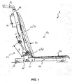
Figure 1 is a side view of a first embodiment of a bath lift device according to the invention; -
Figure 2 is a perspective view of the fixed part of the bath lift device ofFigure 1 ; -
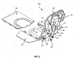
Figure 3 is a perspective view of the moveable part of the bath lift device ofFigure 1 , in which the seat plate is disconnected from the seat frame; -
Figure 4 is a perspective view of the lateral element used in the bath lift device ofFigure 1 ; -
Figure 5 is a perspective view in detail of a suction cup used in the bath lift device ofFigure 1 . -
Figure 6 is a perspective bottom view of a clamping ring used in the bath lift device ofFigure 1 . - In reference to
Figures 1 to 3 , a bath lift device according the present invention is shown. - The
bath lift device 1 of the present invention mainly includes afixed part 10 including a chassis 11-14 adapted to rest, in use, on a floor of the bathtub and amoveable part 20 including aseat frame 21 supporting aseat plate 22 and abackrest 23, saidseat frame 21 being moveable upward and downward relative to the chassis 11-14 via a lifting means 24. - In reference to
Figure 2 , one can see that the chassis 11-14 comprises two tubularupright elements 11 parallel to each other and extending, in use, in an approximately vertical direction. Saidupright elements 11 are connected to their lower ends to aU-shaped element 14 via two connectingelements 13, said U-shapedelement 14 extending, in use, in an approximately horizontal direction. To prevent a tilt back of the chassis 11-14, each connectingelement 13 is advantageously connected to said U-shapedelement 14 so as to be positioned between an end section 14' of said U-shapedelement 14 and the rest of saidU-shaped element 14. Of course, in an alternative embodiment of the present invention, each connectingelement 13 could be connected at one end of saidU-shaped element 14, an additional tubular element being connected to said connectingelement 13 so as to form the end section 14' ofFigure 2 . To improve the stability of the chassis 11-14, said connectingelements 13 are joined by a lateral rod 13' extending between the two lateral flanges of theU-shaped element 14. To improve the stability of the chassis 11-14, saidupright elements 11 are also joined at their upper ends by alateral element 12. As shown inFigure 4 , saidlateral element 12 consists in a curvedtubular element 31 connected at itsends 32 to the two upper ends of theupright elements 11. Saidcurved element 31 is shaped so as to define an upperopen area 33, delimited by theinternal borders 34 of thecurved element 31 and by thesegment 35 joining saidends 32 in the plane defined thecurved element 31. Saidopen area 33 is configured so that themoveable part 20 can be slided upward through saidopen area 33 when the user wants to separate themoveable part 20 from thefixed part 10. In addition, to temporarily connect thefixed part 10 to the floor of the bathtub,suction cup 15 are disposed underneath the chassis 11-14. As shown inFigure 5 , eachsuction cup 15 comprises acentral section 16 fixedly connected to theU-shaped etement 14 at its upper face, saidsection 16 having on its underface a concavity which acts as a sucker for temporarily connect saidcup 15 to the floor of the bathtub. Eachsuction cup 15 comprises also at least one, but preferably two,peelable release tab 17 externally extending from the periphery of thecentral section 16, saidtab 17 releasing the suction between thesuction cup 15 and the floor of the bathtub when itsfree end 18 is raised. In the embodiment illustrated inFigure 5 , saidtab 17 is equipped with atubular section 18 at its free end. Thistubular section 18 is configured so as to be entirely introduced inside a hole 19 formed in the underneath face of theU-shaped element 14 when thetab 17 is elastically twisted so as to align the longitudinal axis of saidtubular section 18 with the longitudinal axis of theupright elements 11. Saidtubular section 18 is also configured so as to be temporarily connected to saidU-shaped element 14 when its longitudinal axis is perpendicular to the longitudinal axis of theupright elements 11. To get this result, one solution consists in configuring saidtubular section 18 so that its length is greater than the diameter of said hole 19. Thus, when the user wants to disconnect the chassis 11-14 from the floor of the bathtub, he needs beforehand to release the suction betweensuction cups 15 and the floor of the bathtub. Accordingly, he has to manually raise the free end of thetabs 17 of twosuction cups 15 positioned at one extremity ofU-shaped element 14 so as to release the suction between saidsuction cups 15 and the floor of the bathtub and, afterwards, if thetabs 17 of thesuction cups 15 positioned at the other extremity are correctly connected to said U-shapedelement 14, he only needs to lift up theU-shaped element 14 from the side which is already disconnected from the floor of the bathtub so that saidtab 17 is raised and the suction between saidcorresponding cups 15 and the floor of the bathtub is released. - In reference to
Figure 3 , one can see that themoveable part 20 comprises aseat frame 21 formed by a first part 21', extending, in use, in an approximately horizontal direction, and by asecond part 21", extending, in use, in an approximately vertical direction, said first part 21' supporting theseat plate 22 and saidsecond part 21" supporting thebackrest 23. Said first part 21' is configured as a U-shaped element and saidsecond part 21" is configured as a pair of parallel upright elements fixedly connected at their lower ends to the U-shaped element. As best seen inFigure 1 , eachupright element 21" is advantageously formed by a lowerlongitudinal section 21"(a) and an upperlongitudinal section 21 "(b), saidsections 21"(a) and 21 "(b) defining an approximately triangular form with thebackrest 23. Saidseat frame 21 is moveable upward and downward relative to the chassis 11-14 via a lifting means 24 arranged on the rear of thebackrest 23. To control the sliding displacement of saidseat frame 21 relative to the chassis 11-14, themoveable part 20 comprises also two pairs of guidingrollers 25 rotatably connected to theupright elements 21" of saidseat frame 21, each pair being slideably mounted onto oneupright element 11 of the chassis 11-14 and the guidingrollers 25 of each pair being disposed, in use, on opposite sides of said oneupright element 11. In the preferred embodiment illustrated inFigure 1 , the guidingrollers 25 of each pair are advantageously positioned on the external lateral side of thelower section 21 "(a) of oneupright element 21" such that the axes of rotation of said guidingrollers 25 are separated by a distance d, said distance d being greater than the diameter of theupright element 11, on which they are slideably mounted. Indeed, in this configuration, the angle α between the plane containing said axes and the longitudinal axis defined by theupright element 11, on which they are slideably mounted, is, in use, different from 90°. Accordingly, this configuration defines a four-points connection between themoveable part 20 and thefixed part 10 which confers a more stable sitting position for the user compared to the two-points connection when α is equal to 90°. Furthermore, the distance d will be advantageously chosen such that said angle α is, in use, less than 45 degrees, and preferably less than 25 degrees. Indeed, by diminishing the angle α, which corresponds to an increased distance d, it is easier for the user to install themoveable part 20 on the fixedpart 10 when saidmoveable part 20 is initially separated from said fixedpart 10. Accordingly, in a first step, the user positions themoveable part 20 relative to the fixedpart 10 so that the angle α is greater than its value when thebath lift device 1 is in use and, in a second step, he lowers themoveable part 20 so that saidmoveable part 20 reaches a position limit and so that bothupright elements 11 are continuously surrounded at two opposite sides by the guidingrollers 25 of each pair and, in a final step, he turns themoveable part 20 round so that the angle α reaches its value when thebath lift device 1 is in use. Finally, to improve the sliding displacement of theseat frame 21, theupper rollers 25 of each pair, and respectively thelower rollers 25 of each pair, are advantageously joined by anaxle 26 extending, in use, in an approximately horizontal direction. - In an alternative embodiment of the present invention, not illustrated on the drawings, it is also possible to use a
seat frame 21 comprisingupright elements 21" that are completely straight. In this case, one guidingroller 25 of each pair will be connected to oneupright elements 21" by a lateral connecting rod extending in a close to perpendicular direction with regard to saidupright element 21". - The lifting means 24 used in the present invention will be configured so as to be lightweight and space-saving. Without to be bound by this specific solution, it will be advantageous to use a lifting means as described in the Canadian patent application
CA 2 397 503 . In particular, such a lifting means prevents that a body part of a bathing person is trapped when the seat plate is moving downward. Accordingly, the lifting means 24 includes an outer spindle 24' within which is received a linearly extendable inner spindle tube (not shown), said outer spindle tube 24' being fixedly connected to theseat frame 21 and said inner spindle tube being supported at itslower end 24" by the chassis 11-14. In particular, saidlower end 24" can be shaped as a fork adapted to be removably connected to the lateral rod 13' of the chassis 11-14. Said inner spindle is linearly extendable via an actuating means (not shown) contained within ahousing 29, saidhousing 29 being fixedly connected to the rear of thebackrest 23. In the embodiment illustrated inFigure 3 , the outer spindle tube 24' is connected to theaxle 26 joining thelower rollers 25 of each pair. This connection is advantageously done by a clampingring 27. In reference toFigure 6 , said clampingring 27 comprises atubular section 40 inside which is received the outer spindle tube 24', saidtubular section 40 comprising a radial aperture 41. At both sides of said radial aperture 41, thetubular section 40 is extended by twolongitudinal sections 42, eachsection 42 comprising a pair of threadedholes 43 configured to join bothsections 42 by two bolts (not shown). Of course, in an alternative embodiment of the present invention, it is also possible to use less ormore sections 42 so as to adapt the internal diameter of thetubular section 40 to the external diameter of the outer spindle tube 24'. On the radially opposite side of thetubular section 40 with regard to saidsections 42 extend twoparallel flanges 44 from the periphery of saidtubular section 40. Eachflange 44 comprises ahole 45 adapted to receive theaxle 26. Of course, in an alternative embodiment of the present invention, it is also possible to use only one flange, said flange being wider than said twoparallel flanges 44 ofFigure 6 . To improve the connection between the outer spindle tube 24' and thetubular section 40, saidsection 40 is advantageously formed by a firsttubular section 46 and a secondtubular section 47, saidfirst section 46 having an internal diameter less than the internal diameter of saidsection 47. Saidfirst section 46 is configured so as to be received inside a corresponding groove (not shown) of said outer spindle tube 24'. In a preferred embodiment of the present invention, the depth of said groove will be advantageously greater than the difference between the internal diameters of saidsecond section 47 and saidfirst section 46. Indeed, this configuration permits to transfer the efforts of the outer spindle tube 24' onto the internal surface of thesecond section 47, and, accordingly, onto a larger surface of the clampingring 27 when saidsecond section 47 is higher than saidfirst section 46. - In reference to
Figure 3 , one can see that twoextension plates 28 can be pivotally connected on both lateral ends of theseat plate 22, saidextension plates 28 being configured so as to rest on the rim of the bathtub when themoveable part 20 is positioned in a raised position so that the user can easily sit inside thebath lift device 1. Therefore, when saidmoveable part 20 is lowered, saidextension plates 28 are folded up so as to be positioned inside the bathtub. - In reference to
Figure 3 , it is also shown that thebackrest 23 comprises at least one rib 23', and preferably two ribs at both left and right sides of saidbackrest 23, said rib 23' extending in a perpendicular direction with regard to the rear of thebackrest 23 and being approximately aligned, in use, with oneupright element 11 of the chassis 11-14. Saidrib 23 is adapted to contact saidupright element 11 when themoveable part 20 is tilting backwards with regard to the fixedpart 10. Such a situation can occur when thelower end 24" of the inner spindle tube of the lifting means 24 is no more supported by the chassis 11-14. Therefore, such a configuration improves the safety of thebath lift device 1 as a whole.
Claims (20)
- Bath lift device (1) for raising and lowering persons into or out of a bathtub comprising two independent parts that can be easily separated, without doing some dismantling operations,:- a fixed part (10) including a chassis (11-14) adapted to rest, in use, on a floor of the bathtub, said chassis (11-14) comprising two tubular upright elements (11) parallel to each other, extending, in use, in a close to vertical direction,- a moveable part (20) including a seat frame (21) supporting a seat plate (22) and a backrest (23), said seat frame (21) being moveable upward and downward relative to the chassis (11-14) via a lifting means (24) and being slideably mounted onto said two upright elements (11),characterized in that said two upright elements (11) are joined by a lateral element (12), said lateral element (12) consisting in a curved tubular element (31) connected at its ends (32) to the two upper ends of the upright elements (11), said tubular element (31) being shaped so as to define an upper open area (33) permitting the sliding upward displacement of the moveable part (20).
- Bath lift device (1) according to the preceding claim, wherein said moveable part (20) comprises two pairs of guiding rollers (25) rotatably connected to said seat frame (21), each pair being slideably mounted onto one upright element (11) and the guiding rollers (25) of each pair being disposed, in use, on opposite sides of said one upright element (11).
- Bath lift device (1) according to the preceding claim, wherein said guiding rollers (25) are fixedly positioned with regard to the backrest (23) so as to define a four-points connection between said moveable part (20) and said fixed part (10) and so that said moveable part (20) is installed on said fixed part (10) by only a combination of tilting and sliding displacements of said seat frame (21).
- Bath lift device (1) according to claim 2 or claim 3, wherein the distance (d) separating the axes of rotation of the guiding rollers (25) of each pair is chosen such that the angle (α) between the plane containing said axes and the longitudinal axis of the upright element (11), onto which they are slideably mounted, is, in use, different from 90°.
- Bath lift device (1) according to the preceding claim, wherein the distance (d) separating the axes of rotation of the guiding rollers (25) of each pair is chosen such that the angle (α) between the plane containing said axes and the longitudinal axis of the upright element (11), onto which they are slideably mounted, is, in use, less than 45 degrees, and preferably less than 25 degrees.
- Bath lift device (1) according to any one of the claims 1 to 5, wherein said seat frame (21) comprises a first part (21'), extending in use in an approximately horizontal direction, and a second part (21"), extending in use in an approximately vertical direction, said first part (21') supporting the seat plate (22) and said second part (21 ") supporting the backrest (23).
- Bath lift device (1) according to the preceding claim, wherein said second part (21 ") is configured as a pair of parallel upright elements, each upright element comprising a lower longitudinal section (21 "a) and an upper longitudinal section (21"b), said lower and upper sections (21 "a, 21 "b) defining an approximately triangular form with the backrest (23).
- Bath lift device (1) according to the preceding claim, wherein said guiding rollers (25) are positioned on the external lateral side of said lower section (21"a).
- Bath lift device (1) according to any one of the claims 1 to 8, wherein the backrest (23) comprises at least one rib (23'), said rib extending in a perpendicular direction with regard to the rear of the said backrest (23) and being approximately aligned, in use, with one upright element (11) of the chassis (11-14).
- Bath lift device (1) according to the preceding claim, wherein said backrest (23) comprises two ribs (23') respectively at its left and right sides.
- Bath lift device (1) according to any one of the claims 1 to 10, wherein the lifting means (24) includes an outer spindle tube (24') within which is received a linearly extendable inner spindle tube, said outer spindle tube (24') being fixedly connected to the seat frame (21) and said inner spindle tube being supported at its lower end (24") by the chassis (13').
- Bath lift device (1) according to the preceding claim, wherein the inner spindle tube is linearly extendable via an actuating means contained within a housing (29), said housing (29) being fixedly connected to the rear of the backrest (23).
- Bath lift device (1) according to claim 11 or claim 12, wherein said lower end (24") is shaped as a fork adapted to be removably connected to a lateral rod (13') extending between said two upright elements (11) of the chassis (11-14).
- Bath lift device (1) according to any one of the claims 1 to 13, wherein suction cup (15) are disposed underneath the chassis (14) so as to temporarily connect the fixed part (10) to the floor of the bathtub.
- Bath lift device (1) according to the preceding claim, wherein each suction cup (15) comprises a central section (16) fixedly connected to the chassis (14) at its upper face, said section (16) having on its underface a concavity which acts as a sucker for temporarily connect said suction cup (15) to the floor of the bathtub.
- Bath lift device (1) according to the preceding claim, wherein each suction cup (15) comprises at least one peelable release tab (17) externally extending from the periphery of the central section (16), said tab (17) releasing the suction between the suction cup (15) and the floor of the bathtub when its free end (18) is raised.
- Bath lift device (1) according to the preceding claim, wherein said tab (17) includes a connecting means (18) at its free end, said connecting means (18) being configured so as to temporarily connect said tab (17) to the chassis (14).
- Bath lift device (1) according to the preceding claim, wherein at least one circular hole (19) is formed in the chassis (14), said hole (19) being configured to receive the connecting means (18) of said tab (17), said connecting means (18) consisting in a tubular section having a length greater than the diameter of said hole (19).
- Bath lift device (1) according to any one of the claims 1 to 18, wherein the chassis (11-14) comprises a U-shaped element (14) extending, in use, in an approximately horizontal direction, said U-shaped element (14) being connected to the lower ends of the upright elements (11) via two connecting elements (13).
- Bath lift device (1) according to the preceding claim, wherein each connecting element (13) is connected to said U-shaped element (14) so as to be positioned between an end section (14') of said U-shaped element (14) and the rest of said U-shaped element (14).
Priority Applications (1)
| Application Number | Priority Date | Filing Date | Title |
|---|---|---|---|
| EP15160037.6A EP2898868B9 (en) | 2010-02-11 | 2011-02-11 | Bath lift device |
Applications Claiming Priority (3)
| Application Number | Priority Date | Filing Date | Title |
|---|---|---|---|
| EP10153361A EP2359793A1 (en) | 2010-02-11 | 2010-02-11 | Bath lift device |
| EP11707485.6A EP2533746B1 (en) | 2010-02-11 | 2011-02-11 | Bath lift device |
| EP15160037.6A EP2898868B9 (en) | 2010-02-11 | 2011-02-11 | Bath lift device |
Related Parent Applications (1)
| Application Number | Title | Priority Date | Filing Date |
|---|---|---|---|
| EP11707485.6A Division EP2533746B1 (en) | 2010-02-11 | 2011-02-11 | Bath lift device |
Publications (3)
| Publication Number | Publication Date |
|---|---|
| EP2898868A1 EP2898868A1 (en) | 2015-07-29 |
| EP2898868B1 EP2898868B1 (en) | 2016-10-19 |
| EP2898868B9 true EP2898868B9 (en) | 2017-03-15 |
Family
ID=42320572
Family Applications (3)
| Application Number | Title | Priority Date | Filing Date |
|---|---|---|---|
| EP10153361A Withdrawn EP2359793A1 (en) | 2010-02-11 | 2010-02-11 | Bath lift device |
| EP15160037.6A Not-in-force EP2898868B9 (en) | 2010-02-11 | 2011-02-11 | Bath lift device |
| EP11707485.6A Not-in-force EP2533746B1 (en) | 2010-02-11 | 2011-02-11 | Bath lift device |
Family Applications Before (1)
| Application Number | Title | Priority Date | Filing Date |
|---|---|---|---|
| EP10153361A Withdrawn EP2359793A1 (en) | 2010-02-11 | 2010-02-11 | Bath lift device |
Family Applications After (1)
| Application Number | Title | Priority Date | Filing Date |
|---|---|---|---|
| EP11707485.6A Not-in-force EP2533746B1 (en) | 2010-02-11 | 2011-02-11 | Bath lift device |
Country Status (2)
| Country | Link |
|---|---|
| EP (3) | EP2359793A1 (en) |
| WO (1) | WO2011098974A2 (en) |
Family Cites Families (6)
| Publication number | Priority date | Publication date | Assignee | Title |
|---|---|---|---|---|
| WO1991011133A1 (en) * | 1990-01-30 | 1991-08-08 | Anscombe Black William Alexand | Bath seat assembly |
| GB9825934D0 (en) * | 1998-11-27 | 1999-01-20 | Sunrise Medical Ltd | Lifting device for use in bath |
| DE19925140A1 (en) * | 1999-06-02 | 2000-12-07 | Walter Gobbers | Entry and exit aid for a bathtub |
| DE10140847A1 (en) | 2001-08-21 | 2003-03-06 | Aquatec Gmbh & Co Kg | Bathtub lifter for the elderly and the disabled |
| SE522825C2 (en) * | 2003-05-05 | 2004-03-09 | Arjo Hospital Equipment Ab | Patient chair has chassis and undercarriage, with seat arrangement connected to chassis for patient, drive being provided for moving seat arrangement in height direction relatively to undercarriage |
| GB2409811A (en) | 2004-01-08 | 2005-07-13 | Mountway Ltd | Battery-operated bath lift |
-
2010
- 2010-02-11 EP EP10153361A patent/EP2359793A1/en not_active Withdrawn
-
2011
- 2011-02-11 EP EP15160037.6A patent/EP2898868B9/en not_active Not-in-force
- 2011-02-11 WO PCT/IB2011/050579 patent/WO2011098974A2/en not_active Ceased
- 2011-02-11 EP EP11707485.6A patent/EP2533746B1/en not_active Not-in-force
Also Published As
| Publication number | Publication date |
|---|---|
| EP2359793A1 (en) | 2011-08-24 |
| EP2898868A1 (en) | 2015-07-29 |
| WO2011098974A2 (en) | 2011-08-18 |
| WO2011098974A3 (en) | 2011-11-10 |
| EP2898868B1 (en) | 2016-10-19 |
| EP2533746A2 (en) | 2012-12-19 |
| EP2533746B1 (en) | 2015-03-25 |
Similar Documents
| Publication | Publication Date | Title |
|---|---|---|
| US10835088B2 (en) | Apparatus for assisting toilet user in standing up | |
| JP2013508011A (en) | Lifting chair with hinged drive module | |
| US20200146513A1 (en) | Sit-down bathing configuration | |
| KR101689129B1 (en) | Lift equipped with electric wheelchair | |
| KR102423485B1 (en) | Auto lifting-moving chair apparatus for parapiegic capable of lifting and moving | |
| EP2898868B1 (en) | Bath lift device | |
| CN209210130U (en) | One kind being convenient for old man children emergency staircase | |
| EP3675789B1 (en) | Person hoisting device and a method for producing motive power of a person hoisting device | |
| CN215607129U (en) | shift car | |
| JP2014217733A (en) | Chair with auxiliary mechanism | |
| RU2445057C1 (en) | Diversified transport means for disabled people | |
| JP2012217718A (en) | Handrail for toilet bowl | |
| KR101197738B1 (en) | Seat apparatus for toilet bowl | |
| KR102816887B1 (en) | Patient lift | |
| KR101528795B1 (en) | Swing for handicapped persons | |
| CN212879868U (en) | A frame lifting mechanism and a wheelchair including the same | |
| CN210185465U (en) | Toilet seat chair assisting in getting up | |
| JP3755822B2 (en) | Nursing wheelchair | |
| EP3130322B1 (en) | Bath lift device | |
| CN216754847U (en) | U-shaped pipe linkage type shifting machine | |
| RU2409339C2 (en) | Mobile lift for movement of disabled people | |
| CN217488486U (en) | Toilet auxiliary device for old people | |
| KR20120001395U (en) | Safety handle for toilet seat with toilet support | |
| KR102619087B1 (en) | Apparatus for helping sitting and standing up | |
| CN215350449U (en) | Chair body opening and closing structure of lift chair |
Legal Events
| Date | Code | Title | Description |
|---|---|---|---|
| PUAI | Public reference made under article 153(3) epc to a published international application that has entered the european phase |
Free format text: ORIGINAL CODE: 0009012 |
|
| 17P | Request for examination filed |
Effective date: 20150320 |
|
| AC | Divisional application: reference to earlier application |
Ref document number: 2533746 Country of ref document: EP Kind code of ref document: P |
|
| AK | Designated contracting states |
Kind code of ref document: A1 Designated state(s): AL AT BE BG CH CY CZ DE DK EE ES FI FR GB GR HR HU IE IS IT LI LT LU LV MC MK MT NL NO PL PT RO RS SE SI SK SM TR |
|
| 17P | Request for examination filed |
Effective date: 20151022 |
|
| RBV | Designated contracting states (corrected) |
Designated state(s): AL AT BE BG CH CY CZ DE DK EE ES FI FR GB GR HR HU IE IS IT LI LT LU LV MC MK MT NL NO PL PT RO RS SE SI SK SM TR |
|
| GRAP | Despatch of communication of intention to grant a patent |
Free format text: ORIGINAL CODE: EPIDOSNIGR1 |
|
| INTG | Intention to grant announced |
Effective date: 20160108 |
|
| GRAS | Grant fee paid |
Free format text: ORIGINAL CODE: EPIDOSNIGR3 |
|
| GRAJ | Information related to disapproval of communication of intention to grant by the applicant or resumption of examination proceedings by the epo deleted |
Free format text: ORIGINAL CODE: EPIDOSDIGR1 |
|
| GRAP | Despatch of communication of intention to grant a patent |
Free format text: ORIGINAL CODE: EPIDOSNIGR1 |
|
| INTG | Intention to grant announced |
Effective date: 20160504 |
|
| GRAS | Grant fee paid |
Free format text: ORIGINAL CODE: EPIDOSNIGR3 |
|
| GRAA | (expected) grant |
Free format text: ORIGINAL CODE: 0009210 |
|
| AC | Divisional application: reference to earlier application |
Ref document number: 2533746 Country of ref document: EP Kind code of ref document: P |
|
| AK | Designated contracting states |
Kind code of ref document: B1 Designated state(s): AL AT BE BG CH CY CZ DE DK EE ES FI FR GB GR HR HU IE IS IT LI LT LU LV MC MK MT NL NO PL PT RO RS SE SI SK SM TR |
|
| REG | Reference to a national code |
Ref country code: GB Ref legal event code: FG4D |
|
| REG | Reference to a national code |
Ref country code: CH Ref legal event code: EP |
|
| REG | Reference to a national code |
Ref country code: AT Ref legal event code: REF Ref document number: 837690 Country of ref document: AT Kind code of ref document: T Effective date: 20161115 |
|
| REG | Reference to a national code |
Ref country code: IE Ref legal event code: FG4D |
|
| REG | Reference to a national code |
Ref country code: DE Ref legal event code: R096 Ref document number: 602011031592 Country of ref document: DE |
|
| REG | Reference to a national code |
Ref country code: NL Ref legal event code: MP Effective date: 20161019 |
|
| REG | Reference to a national code |
Ref country code: LT Ref legal event code: MG4D |
|
| PG25 | Lapsed in a contracting state [announced via postgrant information from national office to epo] |
Ref country code: LV Free format text: LAPSE BECAUSE OF FAILURE TO SUBMIT A TRANSLATION OF THE DESCRIPTION OR TO PAY THE FEE WITHIN THE PRESCRIBED TIME-LIMIT Effective date: 20161019 |
|
| REG | Reference to a national code |
Ref country code: AT Ref legal event code: MK05 Ref document number: 837690 Country of ref document: AT Kind code of ref document: T Effective date: 20161019 |
|
| PG25 | Lapsed in a contracting state [announced via postgrant information from national office to epo] |
Ref country code: NO Free format text: LAPSE BECAUSE OF FAILURE TO SUBMIT A TRANSLATION OF THE DESCRIPTION OR TO PAY THE FEE WITHIN THE PRESCRIBED TIME-LIMIT Effective date: 20170119 Ref country code: SE Free format text: LAPSE BECAUSE OF FAILURE TO SUBMIT A TRANSLATION OF THE DESCRIPTION OR TO PAY THE FEE WITHIN THE PRESCRIBED TIME-LIMIT Effective date: 20161019 Ref country code: GR Free format text: LAPSE BECAUSE OF FAILURE TO SUBMIT A TRANSLATION OF THE DESCRIPTION OR TO PAY THE FEE WITHIN THE PRESCRIBED TIME-LIMIT Effective date: 20170120 Ref country code: LT Free format text: LAPSE BECAUSE OF FAILURE TO SUBMIT A TRANSLATION OF THE DESCRIPTION OR TO PAY THE FEE WITHIN THE PRESCRIBED TIME-LIMIT Effective date: 20161019 |
|
| PG25 | Lapsed in a contracting state [announced via postgrant information from national office to epo] |
Ref country code: NL Free format text: LAPSE BECAUSE OF FAILURE TO SUBMIT A TRANSLATION OF THE DESCRIPTION OR TO PAY THE FEE WITHIN THE PRESCRIBED TIME-LIMIT Effective date: 20161019 Ref country code: FI Free format text: LAPSE BECAUSE OF FAILURE TO SUBMIT A TRANSLATION OF THE DESCRIPTION OR TO PAY THE FEE WITHIN THE PRESCRIBED TIME-LIMIT Effective date: 20161019 Ref country code: AT Free format text: LAPSE BECAUSE OF FAILURE TO SUBMIT A TRANSLATION OF THE DESCRIPTION OR TO PAY THE FEE WITHIN THE PRESCRIBED TIME-LIMIT Effective date: 20161019 Ref country code: PL Free format text: LAPSE BECAUSE OF FAILURE TO SUBMIT A TRANSLATION OF THE DESCRIPTION OR TO PAY THE FEE WITHIN THE PRESCRIBED TIME-LIMIT Effective date: 20161019 Ref country code: HR Free format text: LAPSE BECAUSE OF FAILURE TO SUBMIT A TRANSLATION OF THE DESCRIPTION OR TO PAY THE FEE WITHIN THE PRESCRIBED TIME-LIMIT Effective date: 20161019 Ref country code: RS Free format text: LAPSE BECAUSE OF FAILURE TO SUBMIT A TRANSLATION OF THE DESCRIPTION OR TO PAY THE FEE WITHIN THE PRESCRIBED TIME-LIMIT Effective date: 20161019 Ref country code: ES Free format text: LAPSE BECAUSE OF FAILURE TO SUBMIT A TRANSLATION OF THE DESCRIPTION OR TO PAY THE FEE WITHIN THE PRESCRIBED TIME-LIMIT Effective date: 20161019 Ref country code: IS Free format text: LAPSE BECAUSE OF FAILURE TO SUBMIT A TRANSLATION OF THE DESCRIPTION OR TO PAY THE FEE WITHIN THE PRESCRIBED TIME-LIMIT Effective date: 20170219 Ref country code: BE Free format text: LAPSE BECAUSE OF FAILURE TO SUBMIT A TRANSLATION OF THE DESCRIPTION OR TO PAY THE FEE WITHIN THE PRESCRIBED TIME-LIMIT Effective date: 20161019 Ref country code: PT Free format text: LAPSE BECAUSE OF FAILURE TO SUBMIT A TRANSLATION OF THE DESCRIPTION OR TO PAY THE FEE WITHIN THE PRESCRIBED TIME-LIMIT Effective date: 20170220 |
|
| REG | Reference to a national code |
Ref country code: DE Ref legal event code: R097 Ref document number: 602011031592 Country of ref document: DE |
|
| PG25 | Lapsed in a contracting state [announced via postgrant information from national office to epo] |
Ref country code: DK Free format text: LAPSE BECAUSE OF FAILURE TO SUBMIT A TRANSLATION OF THE DESCRIPTION OR TO PAY THE FEE WITHIN THE PRESCRIBED TIME-LIMIT Effective date: 20161019 Ref country code: RO Free format text: LAPSE BECAUSE OF FAILURE TO SUBMIT A TRANSLATION OF THE DESCRIPTION OR TO PAY THE FEE WITHIN THE PRESCRIBED TIME-LIMIT Effective date: 20161019 Ref country code: CZ Free format text: LAPSE BECAUSE OF FAILURE TO SUBMIT A TRANSLATION OF THE DESCRIPTION OR TO PAY THE FEE WITHIN THE PRESCRIBED TIME-LIMIT Effective date: 20161019 Ref country code: SK Free format text: LAPSE BECAUSE OF FAILURE TO SUBMIT A TRANSLATION OF THE DESCRIPTION OR TO PAY THE FEE WITHIN THE PRESCRIBED TIME-LIMIT Effective date: 20161019 Ref country code: EE Free format text: LAPSE BECAUSE OF FAILURE TO SUBMIT A TRANSLATION OF THE DESCRIPTION OR TO PAY THE FEE WITHIN THE PRESCRIBED TIME-LIMIT Effective date: 20161019 |
|
| PLBE | No opposition filed within time limit |
Free format text: ORIGINAL CODE: 0009261 |
|
| STAA | Information on the status of an ep patent application or granted ep patent |
Free format text: STATUS: NO OPPOSITION FILED WITHIN TIME LIMIT |
|
| PG25 | Lapsed in a contracting state [announced via postgrant information from national office to epo] |
Ref country code: BG Free format text: LAPSE BECAUSE OF FAILURE TO SUBMIT A TRANSLATION OF THE DESCRIPTION OR TO PAY THE FEE WITHIN THE PRESCRIBED TIME-LIMIT Effective date: 20170119 Ref country code: IT Free format text: LAPSE BECAUSE OF FAILURE TO SUBMIT A TRANSLATION OF THE DESCRIPTION OR TO PAY THE FEE WITHIN THE PRESCRIBED TIME-LIMIT Effective date: 20161019 Ref country code: SM Free format text: LAPSE BECAUSE OF FAILURE TO SUBMIT A TRANSLATION OF THE DESCRIPTION OR TO PAY THE FEE WITHIN THE PRESCRIBED TIME-LIMIT Effective date: 20161019 |
|
| REG | Reference to a national code |
Ref country code: DE Ref legal event code: R119 Ref document number: 602011031592 Country of ref document: DE |
|
| 26N | No opposition filed |
Effective date: 20170720 |
|
| PG25 | Lapsed in a contracting state [announced via postgrant information from national office to epo] |
Ref country code: MC Free format text: LAPSE BECAUSE OF FAILURE TO SUBMIT A TRANSLATION OF THE DESCRIPTION OR TO PAY THE FEE WITHIN THE PRESCRIBED TIME-LIMIT Effective date: 20161019 |
|
| REG | Reference to a national code |
Ref country code: CH Ref legal event code: PL |
|
| GBPC | Gb: european patent ceased through non-payment of renewal fee |
Effective date: 20170211 |
|
| PG25 | Lapsed in a contracting state [announced via postgrant information from national office to epo] |
Ref country code: CH Free format text: LAPSE BECAUSE OF NON-PAYMENT OF DUE FEES Effective date: 20170228 Ref country code: LI Free format text: LAPSE BECAUSE OF NON-PAYMENT OF DUE FEES Effective date: 20170228 |
|
| REG | Reference to a national code |
Ref country code: IE Ref legal event code: MM4A |
|
| PG25 | Lapsed in a contracting state [announced via postgrant information from national office to epo] |
Ref country code: SI Free format text: LAPSE BECAUSE OF FAILURE TO SUBMIT A TRANSLATION OF THE DESCRIPTION OR TO PAY THE FEE WITHIN THE PRESCRIBED TIME-LIMIT Effective date: 20161019 |
|
| REG | Reference to a national code |
Ref country code: FR Ref legal event code: ST Effective date: 20171031 |
|
| PG25 | Lapsed in a contracting state [announced via postgrant information from national office to epo] |
Ref country code: LU Free format text: LAPSE BECAUSE OF NON-PAYMENT OF DUE FEES Effective date: 20170211 |
|
| PG25 | Lapsed in a contracting state [announced via postgrant information from national office to epo] |
Ref country code: FR Free format text: LAPSE BECAUSE OF NON-PAYMENT OF DUE FEES Effective date: 20170228 Ref country code: DE Free format text: LAPSE BECAUSE OF NON-PAYMENT OF DUE FEES Effective date: 20170901 |
|
| PG25 | Lapsed in a contracting state [announced via postgrant information from national office to epo] |
Ref country code: IE Free format text: LAPSE BECAUSE OF NON-PAYMENT OF DUE FEES Effective date: 20170211 Ref country code: GB Free format text: LAPSE BECAUSE OF NON-PAYMENT OF DUE FEES Effective date: 20170211 |
|
| PG25 | Lapsed in a contracting state [announced via postgrant information from national office to epo] |
Ref country code: MT Free format text: LAPSE BECAUSE OF NON-PAYMENT OF DUE FEES Effective date: 20170211 |
|
| PG25 | Lapsed in a contracting state [announced via postgrant information from national office to epo] |
Ref country code: HU Free format text: LAPSE BECAUSE OF FAILURE TO SUBMIT A TRANSLATION OF THE DESCRIPTION OR TO PAY THE FEE WITHIN THE PRESCRIBED TIME-LIMIT; INVALID AB INITIO Effective date: 20110211 |
|
| PG25 | Lapsed in a contracting state [announced via postgrant information from national office to epo] |
Ref country code: CY Free format text: LAPSE BECAUSE OF FAILURE TO SUBMIT A TRANSLATION OF THE DESCRIPTION OR TO PAY THE FEE WITHIN THE PRESCRIBED TIME-LIMIT Effective date: 20161019 |
|
| PG25 | Lapsed in a contracting state [announced via postgrant information from national office to epo] |
Ref country code: MK Free format text: LAPSE BECAUSE OF FAILURE TO SUBMIT A TRANSLATION OF THE DESCRIPTION OR TO PAY THE FEE WITHIN THE PRESCRIBED TIME-LIMIT Effective date: 20161019 |
|
| PG25 | Lapsed in a contracting state [announced via postgrant information from national office to epo] |
Ref country code: TR Free format text: LAPSE BECAUSE OF FAILURE TO SUBMIT A TRANSLATION OF THE DESCRIPTION OR TO PAY THE FEE WITHIN THE PRESCRIBED TIME-LIMIT Effective date: 20161019 |
|
| PG25 | Lapsed in a contracting state [announced via postgrant information from national office to epo] |
Ref country code: AL Free format text: LAPSE BECAUSE OF FAILURE TO SUBMIT A TRANSLATION OF THE DESCRIPTION OR TO PAY THE FEE WITHIN THE PRESCRIBED TIME-LIMIT Effective date: 20161019 |