EP2898755B1 - System and method for managing lighting systems - Google Patents
System and method for managing lighting systems Download PDFInfo
- Publication number
- EP2898755B1 EP2898755B1 EP13792978.2A EP13792978A EP2898755B1 EP 2898755 B1 EP2898755 B1 EP 2898755B1 EP 13792978 A EP13792978 A EP 13792978A EP 2898755 B1 EP2898755 B1 EP 2898755B1
- Authority
- EP
- European Patent Office
- Prior art keywords
- light source
- cri
- illuminance
- target level
- peak
- Prior art date
- Legal status (The legal status is an assumption and is not a legal conclusion. Google has not performed a legal analysis and makes no representation as to the accuracy of the status listed.)
- Active
Links
Images


Classifications
-
- H—ELECTRICITY
- H05—ELECTRIC TECHNIQUES NOT OTHERWISE PROVIDED FOR
- H05B—ELECTRIC HEATING; ELECTRIC LIGHT SOURCES NOT OTHERWISE PROVIDED FOR; CIRCUIT ARRANGEMENTS FOR ELECTRIC LIGHT SOURCES, IN GENERAL
- H05B47/00—Circuit arrangements for operating light sources in general, i.e. where the type of light source is not relevant
- H05B47/10—Controlling the light source
- H05B47/105—Controlling the light source in response to determined parameters
- H05B47/11—Controlling the light source in response to determined parameters by determining the brightness or colour temperature of ambient light
-
- H—ELECTRICITY
- H05—ELECTRIC TECHNIQUES NOT OTHERWISE PROVIDED FOR
- H05B—ELECTRIC HEATING; ELECTRIC LIGHT SOURCES NOT OTHERWISE PROVIDED FOR; CIRCUIT ARRANGEMENTS FOR ELECTRIC LIGHT SOURCES, IN GENERAL
- H05B45/00—Circuit arrangements for operating light-emitting diodes [LED]
- H05B45/20—Controlling the colour of the light
- H05B45/22—Controlling the colour of the light using optical feedback
-
- H—ELECTRICITY
- H05—ELECTRIC TECHNIQUES NOT OTHERWISE PROVIDED FOR
- H05B—ELECTRIC HEATING; ELECTRIC LIGHT SOURCES NOT OTHERWISE PROVIDED FOR; CIRCUIT ARRANGEMENTS FOR ELECTRIC LIGHT SOURCES, IN GENERAL
- H05B47/00—Circuit arrangements for operating light sources in general, i.e. where the type of light source is not relevant
- H05B47/10—Controlling the light source
- H05B47/17—Operational modes, e.g. switching from manual to automatic mode or prohibiting specific operations
-
- H—ELECTRICITY
- H05—ELECTRIC TECHNIQUES NOT OTHERWISE PROVIDED FOR
- H05B—ELECTRIC HEATING; ELECTRIC LIGHT SOURCES NOT OTHERWISE PROVIDED FOR; CIRCUIT ARRANGEMENTS FOR ELECTRIC LIGHT SOURCES, IN GENERAL
- H05B47/00—Circuit arrangements for operating light sources in general, i.e. where the type of light source is not relevant
- H05B47/10—Controlling the light source
- H05B47/175—Controlling the light source by remote control
-
- H—ELECTRICITY
- H05—ELECTRIC TECHNIQUES NOT OTHERWISE PROVIDED FOR
- H05B—ELECTRIC HEATING; ELECTRIC LIGHT SOURCES NOT OTHERWISE PROVIDED FOR; CIRCUIT ARRANGEMENTS FOR ELECTRIC LIGHT SOURCES, IN GENERAL
- H05B47/00—Circuit arrangements for operating light sources in general, i.e. where the type of light source is not relevant
- H05B47/10—Controlling the light source
- H05B47/105—Controlling the light source in response to determined parameters
- H05B47/115—Controlling the light source in response to determined parameters by determining the presence or movement of objects or living beings
-
- Y—GENERAL TAGGING OF NEW TECHNOLOGICAL DEVELOPMENTS; GENERAL TAGGING OF CROSS-SECTIONAL TECHNOLOGIES SPANNING OVER SEVERAL SECTIONS OF THE IPC; TECHNICAL SUBJECTS COVERED BY FORMER USPC CROSS-REFERENCE ART COLLECTIONS [XRACs] AND DIGESTS
- Y02—TECHNOLOGIES OR APPLICATIONS FOR MITIGATION OR ADAPTATION AGAINST CLIMATE CHANGE
- Y02B—CLIMATE CHANGE MITIGATION TECHNOLOGIES RELATED TO BUILDINGS, e.g. HOUSING, HOUSE APPLIANCES OR RELATED END-USER APPLICATIONS
- Y02B20/00—Energy efficient lighting technologies, e.g. halogen lamps or gas discharge lamps
- Y02B20/40—Control techniques providing energy savings, e.g. smart controller or presence detection
Definitions
- This application is related to the field of lighting and more particularly to a system and methods for managing light to provide for increased luminous efficacy and reduced costs.
- conventional lighting systems use a significant amount of energy as the lighting sources may be in operation even when there is no need for the operation of the light source. For example, in an office or home having a window, the entry of natural light into the office may mitigate the need for the operation of the lighting system.
- florescent and CFL Compact Florescent Light
- LED Light Emitting Diodes
- motion-sensors are used to turn-on lighting sources when a user enters an area. The lighting is turned off when the user exits the area and no subsequent motion is detected.
- photo-sensors are used to reduce the intensity of light sources based on an ambient light condition surrounding the lighting sources.
- a method for managing lighting in an environment comprising: receiving illuminance information associated with at least one artificial ligting source within said environment; determining an illuminance value associated with a natural light source; determining a measure of said illuminance of said natural light source with respect to an illuminance of a mixed light, said mixed light representing said at least one artificial lighting source and said natural light source; adjusting said illuminance of said at least one artificial light source to achieve a target level of illuminance of said mixed light; and determining at least one additional characteristic of said mixed light based on a corresponding at least one additional characteristic of said at least one artificial light source and said natural light source; and adjusting said at least one additional characteristic of said at least one artificial light source to maintain a target level of said at least on additional characteristic, wherein said adjustment is based on said determined measure of illuminance of said natural light source with respect to said illuminance of a mixed light.
- artificial lighting source may represent one or more different types of lighting sources, such as Light Emitting Diode (LED), and other similar type electrical light sources.
- LED Light Emitting Diode
- a system for managing lighting within an environment comprises a plurality of sensor units within said environment; a computer or processor in communication with said plurality of sensor units and a memory, the memory including code, which when accessed by said processor, causes said processor to execute the steps of: receiving inputs from selected ones of said plurality of sensor units; determining each of an illuminance from at least one artificial lighting source and a natural light source; determining a factor associated with the percentage of illuminance provided by said natural light source with respect to a total illuminance provided by a combination of said natural light source and said at least one artificial lighting source; and adjusting at least one of: the illuminance of said at least one artificial light source and at least one additional characteristic of said at least one artificial light source to a corresponding target level based on said illuminance of said natural light source and a corresponding at least one additional characteristic associated with said natural light source, wherein said adjusting of said at least one additional characteristic is based on said determined factor.
- the characteristics of may be adjusted based on natural lighting conditions, demand response signal, occupancy sensing, scheduling and operating conditions.
- Figure 1A represents an exemplary electrical network 100 comprising a power source 110, an electrical grid 120 receiving power from the power source 110 and providing the power to a plurality of load devices within corresponding area 130, 140.
- Power source 110 may be one or more of a coal-fired electrical generation plant, a nuclear electrical generation plant, a hydro-electrical generation plant or any other conventional electrical generation plant.
- power source 110 may be a renewal energy generation plant. For example, wind, solar, biofuel, etc.
- the areas or environments 130, 140 may represent office buildings, shopping malls, homes, garages, parking lots, tunnels, and other similar areas that require electrical power to provide illumination in one or more areas.
- area 130 depicts different enclosed areas 134, 136, 138 and two open areas 135, 137. Power is provided to each of these areas via a power distribution system 132.
- Area 140 similarly, illustrates three enclosed areas 144, 146, 148 and two open areas 145, 147, which receive power from power distribution system 142.
- areas 130, 140 and the number of enclosed and open areas within each of these areas 130, 140 is only to illustrate the principles of the present invention and the number of areas and enclosed and open areas within each area 130, 140 may be changed without altering the scope of the invention claimed.
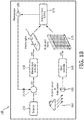
- Figure 1B illustrates an exemplary light management system 150.
- Figure 1B illustrates a light management system suitable for an area such as 134, which includes a window that provides for entry of natural light into the area.
- area such as 134
- Figure 1B illustrates a light management system suitable for an area such as 134, which includes a window that provides for entry of natural light into the area.
- the principles of the light management system 150 depicted in Figure 1B would also be applicable to other area (e.g., 136 and 138) with appropriate inclusion or removal of the blind controller 165 and corresponding adjustment to the set point 198.
- natural light 160 enters an area (or space or zone) typically through one or more window and/or skylights.
- the illuminance of the entering natural light may be measured by one or more exterior sensors or solar trackers 155.
- Information from the exterior sensors may be provided to a blind controller 165 that provides control signals to motorized blinds 170 to increase and/or decrease the amount of natural light entering the space or environment.
- the blind controller may, for example, include a processor that determines a position (height and slat angle of the blind elements) based on a desired level of natural light. This desired level of natural light may be predetermined based on time, for example, or may be provided by an external input (not shown).
- an electric light (artificial light) controller 180 provides control signals to one or more electric or artificial light sources 190.
- the control signals may be used to adjust an illuminance of the artificial light source and, as will be described with regard to the invention claimed, one or more additional characteristics of the artificial or electric light source 190.
- the combination of the natural light provided to through the motorized blinds 170 and the artificial light provided through the electric light source 190 is then measured by a photosensor 195.
- Photosensor can ascertain the contribution of daylight and artificial light to overall illuminance.
- An output of the photosensor 190 is then provided to in this illustrated example, an adder 197, that determines a desired level of illuminance (and other additional characteristics) of the artificial or electric light source 190, based on a desired set point 198.
- the set point 198 may be determined based on criteria, such as occupancy, time of day, utility pricing, user input etc.
- Figure 1B illustrates element 197 as an adder, it would be recognized that the element 197 may also represent a processor that processes the information provided digitally. Similarly, the elements of setpoint 198, electric light controller 180 and blind controller 165 may also be represented by one or more processors that process information provided in a digit manner.
- the set point for illuminance and other additional characteristics of the electric light source may be set in a predetermined manner or schedule, such as based on time of day, or may be set in response to received commands (not shown) that require that the electric or artificial light sources be adjusted based on changing conditions.
- a utility supplier in cases of emergency, may require that the electrical consumption be reduced and, thus issue commands that cause the set point to be changed and, hence, overriding any previous predetermined schedule.
- the set point may be changed from a predetermined schedule based on whether the space or area remains occupied during times that the predetermined schedule fails to consider that space or area being occupied.
- the set point may be changed from a predetermined schedule based on a received input value.
- a space that is unoccupied may be operating in a low lighting condition mode (e.g., a museum) when a space is unoccupied.
- a low lighting condition mode e.g., a museum
- an input may be received (from a motion sensor) that indicates the space may be occupied and the light condition may be raised to a higher or more comfortable lighting mode.
- a space that is occupied may be operating in a comfortable lighting mode but may require a further higher lighting condition upon demand. In this case, an input may be processed that causes an even higher level of lighting to be achieved.
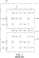
- Figure 2 illustrates an expanded view of areas 134, 135, 136 within area 130.
- Area 134 for example, includes at least one window 220 and a door 210.
- Window 220 allows the entry of a natural light into the area 130.
- Area 130 further includes at least one illumination or lighting element 240 that provides lighting to the area.
- a switch 230 turns on or off selected ones of the lighting elements 240 within area 130.
- Switch 230 may be one of a conventional on/off switch, a motion sensor switch, and an ambient light sensor or other device that may control the illumination output of lighting elements 240.
- Area 135 is on open or utility area that also includes at least one lighting element 240.
- the utility area 135 may represent a corridor between different areas.
- a switch controlling the lighting elements 240 within the utility area 135 may be local or may be remote to the area, wherein the remote switch may control lighting elements in a plurality of utility areas.
- Area 136 represents an enclosed area that includes a door 250 but lacks a window. In this case, the illumination provided by illumination or lighting elements is the only source of illumination in area 136.
- area 134 which includes both daylight and at least one electrical (i.e., artificial) light source
- the intensity of the light generated by the artificial light source may be reduced as the intensity of the daylight increases.
- Luminous efficacy of a source is a measure of how efficiently a light source produces visible light. It is the ratio of total luminous flux emitted and input electric power. Luminous efficacy is typically expressed in lumens per Watt (lm/W) in SI units.
- CRI is the measure of a light source's ability to render the true colors of physical objects in comparison with an ideal or natural light source.
- the color rendering performance of a source is determined by its spectral power distribution.
- a broad emission spectrum distributed throughout the visible region generally results in high CRIs.
- a predefined form of natural light and a black body radiator have a CRI value of 100.
- CRI values in the 70s are considered 'acceptable', and values greater than 80 are considered as 'good'.
- Higher CRI light sources are desirable in studios, museums, art galleries and exhibition halls whereas high luminous efficacy sources are desirable in street lighting applications.
- Luminous efficacy and color rendering are determined solely by the spectrum of the source.
- Modern light sources, such as LEDs, enable dynamic tuning of CRIs.
- the CRI of a combination of daylight and artificial light i.e., mixed-light
- the CRI of the daylight is close to 100
- the contribution of daylight in the mixed light increases then the CRI of artificial light source can be reduced while maintaining the CRI of the mixed light above a desired, target, or predetermined level.
- the CRI of the artificial light source can be set to a desired value (e.g., 85) to maintain a quality lighting environment.
- the contribution of daylight and artificial light are equal (e.g.
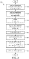
- FIG. 3 illustrates a flow chart of an exemplary process 300 for controlling CRI in view of a lighting condition in accordance with the principles of invention.
- overall illumination at a reference location (e.g., area 134), is the sum of daylight illuminance, I D , and artificial light illuminance, I E .
- a determination is made of the illumination of the electric (artificial) light intensity and at step 320 a determination is made of the illuminance of the daylight (natural light) at the reference location.
- a determination is made of a ratio (denoted by ⁇ ) of daylight illuminance I E to overall illuminance (I D + I E ) at the reference location.
- ⁇ I D I D + I E , 0 ⁇ ⁇ ⁇ 1
- the CRI of each of the artificial light sources, the daylight and the mixed light are obtained and/or determined.
- the CRI of daylight, electric light and mixed (i.e., daylight + electric light) light are denoted by C D , C E and C M respectively.
- the CRI of daylight is well known and can be fixed (block 350).
- the real-time value of ⁇ can be determined using photo-sensors (see Figure 1B ).
- the preferred CRI of mixed light is application dependent.
- CRI values in the 70s are considered 'acceptable', and values greater than 80 are considered as 'good'.
- a target CRI value may be set based on conditions that may be determined based on the desires of the user.
- the desired value of CRI for the mixed light can also be fixed (block 360).
- a minimum value of CRI for electric light to maintain a CRI of mixed light at or above a desired threshold (target level) can be derived at block 370 as: C E ⁇ Max 0 C M ⁇ ⁇ ⁇ C D 1 ⁇ ⁇
- maintaining the CRI of electric light at least C E will ensure that CRI of mixed light is at least C M .
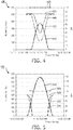
- Figure 4 illustrates a graph 400 of the operation of the adjustment of the CRI in view of a change in natural light that may enter an enclosed area, (e.g., area 134) while maintaining a desired or predetermined CRI of mixed light according to a predetermined schedule in accordance with the principles of the invention.
- Figure 4 represents, on the x-axis a time of day between 12:00AM of an exemplary date of January 1, 2012, through 12:00AM of the next day (i.e., January 2, 2012).
- the left most y-axis represents an illuminance (in lux) of an area, a space or an environment and the right most y-axis represents the CRI within the space (or environment).
- Line 410 represents a typical variation in daylight illuminance (in lux) throughout the day at a reference location (space, environment) between the times of 12AM of one day through to 12AM of the next day.
- daylight illuminance in lux
- the illuminance of the natural light increases from a minimum value (at 6AM) to a maximum value (e.g., 380 lux) at 12Pm back to a minimum value (at 6PM).
- a target illuminance at the reference location is 500 lux.
- the artificial light sources are dimmed (i.e., intensity dimming) in proportion to the increase in daylight illuminance.
- the illuminance contributed by the artificial light sources which is depicted by line 430decreases as the daylight illuminance increases.
- the artificial light source illuminance which may be initially set at the target illuminance of 500 lux to maintain the target illuminance when no daylight is present, is reduced as the daylight illuminance increases from approximately 6AM to approximately 12PM.
- the electric light source illuminance may then be increased as the daylight illuminance decreases from 12PM to 6AM, such that the illuminance of the mixed light created by the combination of the daylight and artificial light sources maintains the desired illuminance (e.g., 500 lux).
- line 405 illustrates a typical CRI of natural light (i.e., 100 percent) and line 440 illustrates the varying CRI of the electric light source according to the principles of this invention in order to maintain a desired CRI (i.e., 85 as presented by line 420) of the mixed light.
- the CRI of the electrical light source is set to a desired value (e.g., 85) in the absence of daylight (e.g., between 12AM and 6AM). As the daylight increases from 6AM to 12PM the CRI of the electrical light sources is altered as the electrical light sources are intensity dimmed.
- the CRI of the mixed light may be maintained at the desired level (e.g., 85) as represented by line 420.
- the CRI of the electrical light source(s) in again increased such that the combined CRI of the mixed light (i.e., daylight and artificial light source) is maintained at the desired level (e.g., 85).
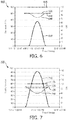
- Figure 5 illustrates a graph 500 of another exemplary operation of the adjustment of the CRI of an illumination source in accordance with the principles of the invention.
- the x-axis and the right y- axis and left y-axis of Figure 5 are the same as those of Figure 4 and need not be repeated herein.
- Line 510 represents a typical variation in daylight illuminance (in lux) throughout the day at a reference location between the times of 12AM through to 12AM, as previously described.
- a target illuminance at the reference location e.g., area 134
- the electric lights are dimmed in proportion to the daylight which is depicted by line 530 (intensity dimming), as previously described with regard to Figure 4 .
- the output of the illuminating or artificial light source(s) is driven to zero (line 540).
- the CRI of the artificial light source is also zero and the CRI of the mixed light rises from 85 (line 520) to 100 (line 505), which is comparable to the CRI of the natural light.
- the illuminance of the daylight falls below the target illuminance (at approximately 2PM) and the artificial light source(s) is turned on to provide sufficient illuminance to maintain the target illuminance.
- the illuminance from the artificial light source(s) increases as the daylight decreases such that the target illuminance (e.g., 500 lux) is maintained.
- the CRI of the artificial light sources is increased, as represented by line 530 to maintain the mixed light CRI at the desired level (e.g., 85).
- Figures 6 and 7 illustrate graphs 600, 700, respectively, of an exemplary operation of the adjustment of the CRI of an illumination, electrical, or artificial light source without intensity dimming of the artificial light source in accordance with the principles of the invention.
- the axis of Figures 6 and 7 are similar to those described with regard to Figure 4 and the description of these quantities need not be repeated again, herein.
- line 610 represents the illuminance of the natural light
- line 630 represents the illuminance contributed by the artificial light source.
- Lines 605 and 620 represent the CRI of the natural light and a target mixed light, respectively, as previously described.
- Line 640 represents the adjustment to the CRI of the electric light sources as the illuminance of the daylight (line 610) increases (and decreases) to maintain the target CRI of the mixed light (daylight + light source) at the target level (e.g., 85).
- the CRI of the artificial light source is adjusted, as previously described (line 640), while the illuminance of the artificial light source remains constant as the light source(s) is not dimmed (line 630).
- Figure 7 which illustrates a case similar to Figure 5 , wherein the illuminance of the daylight exceeds the target illuminance (e.g., 500 lux) and similar to Figure 6 , wherein the artificial sources are not dimmed.
- line 710 represents the illuminance of the natural light, which becomes greater than the desired target luminance (i.e., 500 lux) during the period approximately between 10AM and 2PM.
- Line 705 represents the CRI of the natural light (i.e., 100), as previously described and e line 720 represents the CRI of the mixed light maintained at the desired target level (e.g., 85).
- Line 730 represents the illuminance of the artificial light source(s) and line 740 illustrates the adjustment of the CRI of the artificial light source as the illuminance of the natural light increases without dimming of the light sources.
- the CRI of the artificial light sources is adjusted (line 740) as the illuminance of the natural light source (i.e., daylight) increases/decreases.
- the principles of the invention may be extended to account for non-uniform distribution of daylight and multiple light sources in a space
- the daylight enters the space through windows or skylights.
- Daylight intensity decreases in the interior of the space as the distance from window or skylight increases.
- most spaces are lit using multiple light sources/luminaires (see Figure 2 , elements 240).
- the overall CRI at a reference location within an area e.g., 130
- the weight of each light source is the fraction of illuminance contributed by that source.
- M reference points may be defined in the environment where a desired CRI of mixed light above a pre-defined value C M is to be maintained.
- the illuminance contributed by electric light source i at a reference point j is denoted by I ij .
- the illuminance contributed by daylight at a reference point j is denoted by I Dj .
- the CRI of daylight is constant and denoted by C D .
- the objective is to find the CRI of each electric light source (i) denoted by c Ei such that the sum of CRIs of all the electric light sources is minimized.
- the feasible range of c Ei is bounded by upper bound (CEMax) and lower bounds (C EMin ). Note that in the below problem formulation, except for the CRIs of electric light sources (c Ei ), all the other quantities are fixed.
- the illuminance (I Dj ) contributed by daylight at a reference pointj can be measured by a photo-sensor located at point j when all the electric light sources are turned off.
- the illuminance contributed by electric light source i at a reference pointj can be measured by a photo-sensor placed at point j when electric light source i is on but all other light sources are turned off and daylight is absent. If daylight is present then daylight can be subtracted from the photo-sensor measurement to derive the contribution of a given electric light.
- the CRI of the illumination source may be adjusted to take advantage of a tradeoff between CRI and luminous efficiency.
- kWHr kilowatthours
- the rates of electricity vary by time-of-day and seasonally.
- the utility companies charge higher tariff during on-peak durations and lower tariffs during off-peak durations.
- Some utility companies have three tire rate schedule for on-peak, mid-peak and off-peak durations where electricity rates during on-peak durations are typically the highest followed by mid-peak duration, followed by off-peak duration.
- the CRI of the artificial illumination light sources may be set to a specified minimum value whereas during on-peak durations (e.g. Noon to 6 p.m., weekdays except holidays during summer season) the CRI of the electrical light source(s) may be allowed to drift lower while maximizing the luminous efficacy.
- a light source operates in a demand saver mode (e.g. during a demand response or critical peak pricing event)
- attempts to maximize the luminous efficacy while sacrificing the CRI may provide significant savings.
- an area for example, 136 of Figure 2
- the present invention maintains the CRI to a per-defined minimum value while attempting to improve luminous efficacy.
- FIG 8 illustrates state transition diagram 800 of an exemplary embodiment of the invention.
- the light source(s) 240 ( Figure 2 ) operates in either a demand saver mode (810) or in a comfort mode (820). Whether a light source operates under demand saver mode (810) or comfort mode (820) is decided based on the demand response signals from the utility or inputs from a facility manger (e.g., power grid).
- a facility manger e.g., power grid
- a higher CRI value is desirable for occupant comfort and visual acuity.
- the light source is driven to maximize the luminous efficacy while maintaining the CRI above a threshold denoted by H in Figure 8 .
- the light source is driven to maximize the luminous efficacy while maintaining the CRI above a threshold denoted by L in Figure 8 .
- L a threshold denoted by L in Figure 8 .
- Additional efficacy gains achievable due to a change in the CRI threshold from a high value H to a low value L is proportional to the absolute difference between H and L. Large difference leads to higher energy savings and vice versa.
- Figure 9 illustrates a state transition diagram 900 of a second aspect of the invention.
- the light source operates in one of the three modes, namely, Off-peak 910, Mid-peak 920 and On-peak 930.
- the state transition among various modes is governed by time of use and/or utility pricing. For example, during off-peak pricing periods, the source operates in an off-peak mode 910. Similarly, during an on-peak pricing period the source operates in an on-peak mode 930.
- the light source is driven to maximize the luminous efficacy while maintaining the CRI above a threshold denoted by H.
- the light source is driven to maximize the luminous efficacy while maintaining the CRI above a threshold denoted by L.
- the light source is driven to maximize the luminous efficacy while maintaining the CRI above a threshold denoted by M.
- M 0 ⁇ L ⁇ M ⁇ H ⁇ 100.
- the light intensity may change with the change in mode of operation.
- the lights may dim in demand saver mode.
- the CCT of the source may also change in addition to the dimming of the source. The principles of this aspect of the invention can be applied irrespective of whether the lights are dimmed, brightened or maintained at the same level, or CCT of the light source is changed or maintained at the same level.
- Another aspect of the invention is to dynamically exploit the trade-off between the CRI and luminous efficacy based on the operating conditions to save energy. For example, when the space is occupied the CRI is set to the specified value (i.e., target values) whereas when space is unoccupied the CRI is allowed to drift lower while maximizing the luminous efficacy. Similarly when a light source operates in energy saver mode, in accordance with the principles of the invention, attempts to maximize the luminous efficacy while sacrificing the CRI is performed whereas in a comfort mode the invention maintains the CRI to a per-defined value while attempting to improve luminous efficacy.
- Figure 10 illustrates a state transition diagram 1000 in areas such as 133, Figure 2 , wherein the lighting may be required to be maintained whether the area is occupied or not, as this area may represent an emergency route.
- the light source 240 operates in either an occupied mode 1010 or in an unoccupied mode 1020. Whether a space (e.g., 133) is occupied or unoccupied is decided based on the input(s) from associated occupancy/motion sensor(s) (or other types of sensors) that monitor the space.
- occupancy sensors are available in the market that can detect whether a space is occupied or unoccupied using Infra-Red, Ultrasound and/or Microwave technology.
- a higher CRI value is desirable for occupant comfort and visual acuity.
- a higher CRI value is preferred for a better picture quality.
- the light source in the occupied state 1010, the light source is driven to maximize the luminous efficacy while maintaining the CRI above a threshold (target value) denoted by H.
- a threshold target value
- the space is vacated (unoccupied)
- the light source is driven to maximize the luminous efficacy while maintaining the CRI above another threshold denoted by L.
- L another threshold
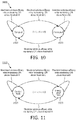
- Figure 11 illustrates a state transition diagram of another embodiment of the invention.
- the light source operates in either a comfort mode 1110 or in an energy saver mode 1120.
- the state transition between the comfort and energy saver modes may be governed by one or more of the following conditions.
- the light source is driven to maximize the luminous efficacy while maintaining the CRI above a threshold (a target value) denoted by H.
- the light source is driven to maximize the luminous efficacy while maintaining the CRI above a threshold (a target value) denoted by L.
- a target value a target value
- L a target value
- the light intensity may change with the change in mode of operation.
- the lights may dim in energy saver mode.
- the principles of this invention can be applied irrespective of whether the lights are dimmed, brightened or maintained at the same level.
- Another aspect of the invention is to dynamically tune the CCT (Correlated Color Temperature) based on the operating conditions to save energy. For example, when the space is occupied the CCT is set to the specified value whereas when space is unoccupied the CCT is sacrificed for higher luminous efficacy. Similarly when a light source operates in energy saver mode, according to the principles of the invention the luminous efficacy may be maximized while allowing the CCT to drift whereas in comfort mode it maintains the CCT to a per-defined value (i.e., target value) while attempting to improve luminous efficacy.
- a per-defined value i.e., target value
- Figure 12 illustrates a state transition diagram of an embodiment of the invention.
- the light source operates in either the occupied mode 1210 or in the unoccupied mode 1220. Whether a space is occupied or unoccupied is decided based on the input(s) from the associated occupancy/motion sensor(s) that monitor the said space.
- occupancy sensors are available in the market that can detect whether a space is occupied or unoccupied using Infra-Red, Ultrasound and/or Microwave technology.
- CCT can be tuned for occupant comfort and visual acuity.
- the surveillance applications when motion is detected, the CCT may be tuned for a better picture quality.
- the light source in the occupied state, the light source is driven to maximize the luminous efficacy while maintaining the CCT near the threshold denoted by A.
- the space is vacated (1120) the light source is driven to maximize the luminous efficacy while maintaining the CCT near a threshold denoted by B.
- a ⁇ B i.e. generating higher CCT cool white light is generally more efficient than generating lower CCT warm white light.
- Additional efficacy gains achievable due change in the CCT threshold is proportional to the absolute difference between A and B. Large difference leads to higher energy savings and vice versa.
- Figure 13 illustrates a state transition diagram 1300 of another embodiment of the invention.
- the light source operates in either the comfort mode 1310 or in the energy saver mode 1320.
- the state transition between the comfort and energy saver modes could be governed by one or more of the following conditions.
- CCT is tuned for visual comfort of the occupants or to meet the requirements of the applications (e.g. photography).
- the light source is driven to maximize the luminous efficacy while maintaining the CCT near a threshold denoted by X.
- the light source is driven to maximize the luminous efficacy while maintaining the CCT near a threshold denoted by Y.
- X typically, X ⁇ Y.
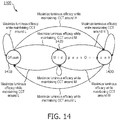
- Figure 14 illustrates a state transition diagram 1400 of yet another embodiment of the invention.
- the light source operates in one of the three modes, namely, Off-peak 1410, Mid-peak 1420 and On-peak 1430.
- the state transition among various modes is governed by time of use and/or utility pricing. For example, during off-peak pricing period, the source operates in off-peak mode. Similarly, during on-peak pricing period the source operates in on-peak mode.
- CCT is tuned for visual comfort of the occupants.
- the light source is driven to maximize the luminous efficacy while maintaining the CCT around a threshold (target value) denoted by L.
- the light source is driven to maximize the luminous efficacy while maintaining the CCT around a threshold (target value) denoted by H.
- the light source is driven to maximize the luminous efficacy while maintaining the CCT around a threshold (target value) denoted by M. Since LED efficiencies are proportional to CCT, higher CCT means higher efficiency. Thus, typically, L ⁇ M ⁇ H.
- the light intensity may change with the change in mode of operation.
- the lights may dim in the off-peak mode.
- the CCT of the source may also change in addition to dimming. The principles of this invention can be applied irrespective of whether the lights are dimmed, brightened or maintained at the same level, or CRI of the light source is changed or maintained at the same level.
- CQS Color Quality Scale
- GAI Gamut Area Index
- GAS Gamut Area Scale
- HRI Color Harmony Rendering Index
- Duv Delta-uv
- the above-described methods according to the present invention can be implemented in hardware, firmware or as software or computer code that can be stored in a recording medium such as a CD ROM, an RAM, a floppy disk, a hard disk, or a magneto-optical disk or computer code downloaded over a network originally stored on a remote non-transitory recording medium or a non-transitory machine readable medium and to be stored on a local recording medium, so that the methods described herein can be rendered in such software that is stored on the recording medium using a general purpose computer(s), or a special processor(s) or in programmable or dedicated hardware(s), such as an ASIC or FPGA.
- a recording medium such as a CD ROM, an RAM, a floppy disk, a hard disk, or a magneto-optical disk or computer code downloaded over a network originally stored on a remote non-transitory recording medium or a non-transitory machine readable medium and to be stored on a local recording medium, so that the methods described here
- the computer(s), the processor(s), microprocessor controller(s) or the programmable hardware(s) include memory components, e.g., RAM, ROM, Flash, etc. that may store or receive software or computer code that when accessed and executed by the computer(s), processor(s) or hardware(s) implement the processing methods described herein.
- memory components e.g., RAM, ROM, Flash, etc.
- the execution of the code transforms the general purpose computer(s) into a special purpose computer(s) for executing the processing shown herein.
Landscapes
- Circuit Arrangement For Electric Light Sources In General (AREA)
Applications Claiming Priority (2)
| Application Number | Priority Date | Filing Date | Title |
|---|---|---|---|
| US201261704026P | 2012-09-21 | 2012-09-21 | |
| PCT/IB2013/058053 WO2014045138A2 (en) | 2012-09-21 | 2013-08-28 | System and method for managing lighting systems |
Publications (2)
| Publication Number | Publication Date |
|---|---|
| EP2898755A2 EP2898755A2 (en) | 2015-07-29 |
| EP2898755B1 true EP2898755B1 (en) | 2021-05-19 |
Family
ID=49622851
Family Applications (1)
| Application Number | Title | Priority Date | Filing Date |
|---|---|---|---|
| EP13792978.2A Active EP2898755B1 (en) | 2012-09-21 | 2013-08-28 | System and method for managing lighting systems |
Country Status (7)
| Country | Link |
|---|---|
| US (1) | US9661722B2 (enExample) |
| EP (1) | EP2898755B1 (enExample) |
| JP (1) | JP6271556B2 (enExample) |
| CN (1) | CN104641729B (enExample) |
| DK (1) | DK2898755T3 (enExample) |
| ES (1) | ES2881476T3 (enExample) |
| WO (1) | WO2014045138A2 (enExample) |
Families Citing this family (27)
| Publication number | Priority date | Publication date | Assignee | Title |
|---|---|---|---|---|
| JP6143772B2 (ja) * | 2011-12-01 | 2017-06-07 | フィリップス ライティング ホールディング ビー ヴィ | 動きによって生じる占有センサ検知の誤検出を防止する方法 |
| US9603223B2 (en) * | 2013-08-15 | 2017-03-21 | Philips Lighting Holding B.V. | Illumination controller |
| WO2015189118A1 (en) | 2014-06-10 | 2015-12-17 | Koninklijke Philips N.V. | Demand response for networked distributed lighting systems |
| EP4024454B1 (en) * | 2014-10-28 | 2023-08-30 | Seoul Semiconductor Co., Ltd. | White light source system |
| FR3034390B1 (fr) * | 2015-03-31 | 2019-05-10 | Systra | Systeme de gestion dynamique des ambiances dans une gare ferroviaire ou souterraine |
| CN105606218B (zh) * | 2016-02-03 | 2017-12-19 | 深圳大学 | 光源显色性性能的光谱诊断方法及系统 |
| US20170223802A1 (en) * | 2016-02-03 | 2017-08-03 | Honeywell International Inc. | Camera-aided controller of illumination |
| CN106231756B (zh) * | 2016-08-25 | 2019-07-19 | 欧普照明股份有限公司 | 照明方法和照明装置 |
| US9795000B1 (en) | 2016-09-14 | 2017-10-17 | Ketra, Inc. | Illumination device, system and method for manually adjusting automated changes in exterior daylight among select groups of illumination devices placed in various rooms of a structure |
| US11202354B2 (en) | 2016-09-14 | 2021-12-14 | Lutron Technology Company Llc | Illumination system and method that presents a natural show to emulate daylight conditions with smoothing dimcurve modification thereof |
| US10582596B2 (en) * | 2016-09-14 | 2020-03-03 | Lutron Ketra, Llc | Illumination device, system and method for manually adjusting automated fading of color temperature changes to emulate exterior daylight |
| MX2019002908A (es) | 2016-09-14 | 2019-11-21 | Lutron Ketra Llc | Dispositivo de iluminacion y metodo para ajustar cambios periodicos en salida de emulacion. |
| US10621836B2 (en) | 2016-09-14 | 2020-04-14 | Lutron Ketra, Llc | Global keypad for linking the control of shows and brightness among multiple zones illuminated by light emitting diodes arranged among a structure |
| US10237945B2 (en) | 2016-09-14 | 2019-03-19 | Lutron Ketra, Llc | Illumination device, system and method for manually adjusting automated periodic changes in emulation output |
| US9930742B1 (en) | 2016-09-14 | 2018-03-27 | Ketra, Inc. | Keypad with color temperature control as a function of brightness among scenes and the momentary or persistent override and reprogram of a natural show and method thereof |
| US9860957B1 (en) * | 2016-11-16 | 2018-01-02 | Osram Sylvania Inc. | CCT tuning daylighting system and method based on luminosity measurements |
| US12264536B2 (en) | 2017-07-26 | 2025-04-01 | Wideband Labs, LLC | Motorized shade with automated configuration and control |
| KR102230459B1 (ko) * | 2017-09-06 | 2021-03-23 | 지엘비텍 주식회사 | D50, d65 고연색성 표준 led 발광 모듈 및 조명 장치 |
| WO2019080123A1 (zh) * | 2017-10-27 | 2019-05-02 | 深圳和而泰智能控制股份有限公司 | 一种照明灯控制方法及其装置、照明灯 |
| US10750597B2 (en) | 2018-05-04 | 2020-08-18 | Crestron Electronics, Inc. | Color temperature sensor |
| US11002605B2 (en) | 2018-05-04 | 2021-05-11 | Crestron Electronics, Inc. | System and method for calibrating a light color sensor |
| DE102018122428A1 (de) * | 2018-09-13 | 2020-03-19 | Osram Opto Semiconductors Gmbh | Verfahren zur steuerung einer beleuchtung eines objekts, system zur steuerung einer beleuchtung eines objekts und kamera |
| US11871495B2 (en) | 2020-07-14 | 2024-01-09 | Lutron Technology Company Llc | Lighting control system with light show overrides |
| US12543255B2 (en) | 2020-07-14 | 2026-02-03 | Lutron Technology Company Llc | Lighting control system with light show overrides |
| CN112738945A (zh) * | 2020-10-21 | 2021-04-30 | 浙江利尔达客思智能科技有限公司 | 一种多点照度采集联动照度调整的控制系统及方法 |
| CN113179570B (zh) * | 2021-05-12 | 2022-07-01 | 清华大学 | 照度控制方法及装置、电子设备和存储介质 |
| KR102728628B1 (ko) * | 2022-06-22 | 2024-11-11 | 주식회사 온유테크 | Led 조명 장치 및 그 동작 방법 |
Family Cites Families (27)
| Publication number | Priority date | Publication date | Assignee | Title |
|---|---|---|---|---|
| US4236101A (en) | 1978-08-18 | 1980-11-25 | Lutron Electronics Co., Inc. | Light control system |
| US4220412A (en) * | 1978-10-25 | 1980-09-02 | Eastman Kodak Company | Illuminant discrimination apparatus and method |
| US4347461A (en) | 1980-10-23 | 1982-08-31 | Robert L. Elving | Incident illumination responsive light control |
| CA1253198A (en) | 1984-05-14 | 1989-04-25 | W. John Head | Compensated light sensor system |
| JP2529476B2 (ja) | 1991-03-05 | 1996-08-28 | 松下電器産業株式会社 | 照明装置 |
| WO1996015649A1 (en) * | 1994-11-11 | 1996-05-23 | Philips Electronics N.V. | Vertical illuminance determines preferred lighting level |
| JPH09507962A (ja) | 1994-11-11 | 1997-08-12 | フィリップス エレクトロニクス ネムローゼ フェンノートシャップ | 昼光レベルの増加によって人工照明を最適化するシステム |
| US5548398A (en) * | 1994-11-22 | 1996-08-20 | Eastman Kodak Company | Illuminant discriminator providing detection of high efficiency illumination |
| JPH10500534A (ja) | 1995-03-10 | 1998-01-13 | フィリップス エレクトロニクス ネムローゼ フェンノートシャップ | 昼光レベルの影響下での人工光の色温度制御用照明装置 |
| US5701058A (en) * | 1996-01-04 | 1997-12-23 | Honeywell Inc. | Method of semiautomatic ambient light sensor calibration in an automatic control system |
| JP2002374539A (ja) | 2001-06-15 | 2002-12-26 | Olympus Optical Co Ltd | ホワイトバランス補正可能なカメラ |
| US7288755B1 (en) * | 2001-10-19 | 2007-10-30 | Brian P. Platner | Portable handheld artificial light detector |
| CN2562057Y (zh) * | 2002-04-20 | 2003-07-23 | 戴智勇 | 变色护眼台灯 |
| US9955551B2 (en) * | 2002-07-12 | 2018-04-24 | Yechezkal Evan Spero | Detector controlled illuminating system |
| US7768189B2 (en) | 2004-08-02 | 2010-08-03 | Lumination Llc | White LEDs with tunable CRI |
| US7111952B2 (en) * | 2003-03-24 | 2006-09-26 | Lutron Electronics Co., Inc. | System to control daylight and artificial illumination and sun glare in a space |
| US7598859B2 (en) | 2004-08-13 | 2009-10-06 | Osram Sylvania Inc. | Method and system for controlling lighting |
| JP2006210045A (ja) * | 2005-01-26 | 2006-08-10 | Matsushita Electric Works Ltd | 照明システム |
| JP2009048989A (ja) * | 2007-07-20 | 2009-03-05 | Toshiba Lighting & Technology Corp | 照明装置 |
| US7845824B2 (en) | 2008-02-19 | 2010-12-07 | Robotham Creative, Inc. | Virtual single light source having variable color temperature with integral thermal management |
| WO2009155605A1 (en) | 2008-06-20 | 2009-12-23 | Energy Focus, Inc. | Led lighting system having a reduced-power usage mode |
| KR100946202B1 (ko) * | 2009-04-02 | 2010-03-09 | 주식회사 케이디파워 | 감성 조명 시스템 |
| US8593073B2 (en) * | 2009-10-15 | 2013-11-26 | Massachusetts Institute Of Technology | Apparatus and methods for interactive illumination |
| US20120001841A1 (en) * | 2010-06-30 | 2012-01-05 | Jeff Gokingco | Identifying ambient light type and illuminance compensation using a plurality of photodetectors |
| JP2012134001A (ja) * | 2010-12-21 | 2012-07-12 | Sharp Corp | Led駆動回路およびこれを用いたled照明灯具 |
| US20130002144A1 (en) * | 2011-06-03 | 2013-01-03 | Osram Sylvania Inc. | Multimode color tunable light source and daylighting system |
| US8860316B2 (en) * | 2011-12-16 | 2014-10-14 | Redwood Systems, Inc. | Selective light sensor and daylight management |
-
2013
- 2013-08-28 DK DK13792978.2T patent/DK2898755T3/da active
- 2013-08-28 CN CN201380049145.4A patent/CN104641729B/zh active Active
- 2013-08-28 JP JP2015532534A patent/JP6271556B2/ja active Active
- 2013-08-28 US US14/429,577 patent/US9661722B2/en active Active
- 2013-08-28 ES ES13792978T patent/ES2881476T3/es active Active
- 2013-08-28 WO PCT/IB2013/058053 patent/WO2014045138A2/en not_active Ceased
- 2013-08-28 EP EP13792978.2A patent/EP2898755B1/en active Active
Non-Patent Citations (1)
| Title |
|---|
| None * |
Also Published As
| Publication number | Publication date |
|---|---|
| CN104641729B (zh) | 2017-05-24 |
| WO2014045138A3 (en) | 2014-05-22 |
| JP2015529388A (ja) | 2015-10-05 |
| US20150237703A1 (en) | 2015-08-20 |
| JP6271556B2 (ja) | 2018-01-31 |
| EP2898755A2 (en) | 2015-07-29 |
| DK2898755T3 (da) | 2021-07-12 |
| US9661722B2 (en) | 2017-05-23 |
| WO2014045138A2 (en) | 2014-03-27 |
| ES2881476T3 (es) | 2021-11-29 |
| CN104641729A (zh) | 2015-05-20 |
Similar Documents
| Publication | Publication Date | Title |
|---|---|---|
| EP2898755B1 (en) | System and method for managing lighting systems | |
| US11339927B2 (en) | Methods, apparatus and systems for providing occupancy-based variable lighting | |
| EP2831971B1 (en) | Methods and apparatus for operating a lighting network according to energy demand and energy supply | |
| US10485068B2 (en) | Methods, apparatus, and systems for providing occupancy-based variable lighting | |
| Li et al. | An analysis of energy-efficient light fittings and lighting controls | |
| US9967952B2 (en) | Demand response for networked distributed lighting systems | |
| Wen et al. | Control of wireless-networked lighting in open-plan offices | |
| CN103503576B (zh) | 用于多个光源的光照控制的设备和方法 | |
| US8729834B1 (en) | System and method for control of lighting systems | |
| Bonomolo et al. | A set of indices to assess the real performance of daylight-linked control systems | |
| AU2023201960A1 (en) | Methods, apparatus and systems for providing occupancy-based variable lighting | |
| Yu et al. | An RTP-based dimming control system for visual comfort enhancement and energy optimization | |
| Petrinska et al. | Lighting control system for public premises, based on evolutionary optimization algorithm | |
| Shackelford et al. | Laboratory Validation of Integrated Lighting Systems Retrofit Performance and Energy | |
| Regnier et al. | ComEd–LBNL ‘Beyond Widgets’ Project Automated Shading Integrated with Lighting and HVAC Controls System Program Manual | |
| WO2012011057A1 (en) | Method and system for controlling the luminous flux of a lighting arrangement |
Legal Events
| Date | Code | Title | Description |
|---|---|---|---|
| PUAI | Public reference made under article 153(3) epc to a published international application that has entered the european phase |
Free format text: ORIGINAL CODE: 0009012 |
|
| 17P | Request for examination filed |
Effective date: 20150421 |
|
| AK | Designated contracting states |
Kind code of ref document: A2 Designated state(s): AL AT BE BG CH CY CZ DE DK EE ES FI FR GB GR HR HU IE IS IT LI LT LU LV MC MK MT NL NO PL PT RO RS SE SI SK SM TR |
|
| AX | Request for extension of the european patent |
Extension state: BA ME |
|
| DAX | Request for extension of the european patent (deleted) | ||
| RAP1 | Party data changed (applicant data changed or rights of an application transferred) |
Owner name: PHILIPS LIGHTING HOLDING B.V. |
|
| RIN1 | Information on inventor provided before grant (corrected) |
Inventor name: PATEL, MAULIN DAHYABHAI |
|
| RAP1 | Party data changed (applicant data changed or rights of an application transferred) |
Owner name: PHILIPS LIGHTING HOLDING B.V. |
|
| RAP1 | Party data changed (applicant data changed or rights of an application transferred) |
Owner name: SIGNIFY HOLDING B.V. |
|
| STAA | Information on the status of an ep patent application or granted ep patent |
Free format text: STATUS: EXAMINATION IS IN PROGRESS |
|
| 17Q | First examination report despatched |
Effective date: 20200103 |
|
| REG | Reference to a national code |
Ref country code: DE Ref legal event code: R079 Ref document number: 602013077550 Country of ref document: DE Free format text: PREVIOUS MAIN CLASS: H05B0037020000 Ipc: H05B0047100000 |
|
| GRAP | Despatch of communication of intention to grant a patent |
Free format text: ORIGINAL CODE: EPIDOSNIGR1 |
|
| STAA | Information on the status of an ep patent application or granted ep patent |
Free format text: STATUS: GRANT OF PATENT IS INTENDED |
|
| RIC1 | Information provided on ipc code assigned before grant |
Ipc: H05B 47/10 20200101AFI20201203BHEP Ipc: H05B 47/11 20200101ALI20201203BHEP Ipc: H05B 47/17 20200101ALI20201203BHEP Ipc: H05B 47/115 20200101ALI20201203BHEP Ipc: H05B 45/20 20200101ALI20201203BHEP |
|
| INTG | Intention to grant announced |
Effective date: 20201217 |
|
| GRAS | Grant fee paid |
Free format text: ORIGINAL CODE: EPIDOSNIGR3 |
|
| GRAA | (expected) grant |
Free format text: ORIGINAL CODE: 0009210 |
|
| STAA | Information on the status of an ep patent application or granted ep patent |
Free format text: STATUS: THE PATENT HAS BEEN GRANTED |
|
| AK | Designated contracting states |
Kind code of ref document: B1 Designated state(s): AL AT BE BG CH CY CZ DE DK EE ES FI FR GB GR HR HU IE IS IT LI LT LU LV MC MK MT NL NO PL PT RO RS SE SI SK SM TR |
|
| REG | Reference to a national code |
Ref country code: GB Ref legal event code: FG4D |
|
| REG | Reference to a national code |
Ref country code: CH Ref legal event code: EP |
|
| REG | Reference to a national code |
Ref country code: DE Ref legal event code: R096 Ref document number: 602013077550 Country of ref document: DE |
|
| REG | Reference to a national code |
Ref country code: AT Ref legal event code: REF Ref document number: 1395257 Country of ref document: AT Kind code of ref document: T Effective date: 20210615 |
|
| REG | Reference to a national code |
Ref country code: IE Ref legal event code: FG4D |
|
| REG | Reference to a national code |
Ref country code: DK Ref legal event code: T3 Effective date: 20210706 |
|
| REG | Reference to a national code |
Ref country code: NL Ref legal event code: FP |
|
| REG | Reference to a national code |
Ref country code: LT Ref legal event code: MG9D |
|
| REG | Reference to a national code |
Ref country code: AT Ref legal event code: MK05 Ref document number: 1395257 Country of ref document: AT Kind code of ref document: T Effective date: 20210519 |
|
| PG25 | Lapsed in a contracting state [announced via postgrant information from national office to epo] |
Ref country code: HR Free format text: LAPSE BECAUSE OF FAILURE TO SUBMIT A TRANSLATION OF THE DESCRIPTION OR TO PAY THE FEE WITHIN THE PRESCRIBED TIME-LIMIT Effective date: 20210519 Ref country code: BG Free format text: LAPSE BECAUSE OF FAILURE TO SUBMIT A TRANSLATION OF THE DESCRIPTION OR TO PAY THE FEE WITHIN THE PRESCRIBED TIME-LIMIT Effective date: 20210819 Ref country code: AT Free format text: LAPSE BECAUSE OF FAILURE TO SUBMIT A TRANSLATION OF THE DESCRIPTION OR TO PAY THE FEE WITHIN THE PRESCRIBED TIME-LIMIT Effective date: 20210519 Ref country code: LT Free format text: LAPSE BECAUSE OF FAILURE TO SUBMIT A TRANSLATION OF THE DESCRIPTION OR TO PAY THE FEE WITHIN THE PRESCRIBED TIME-LIMIT Effective date: 20210519 Ref country code: FI Free format text: LAPSE BECAUSE OF FAILURE TO SUBMIT A TRANSLATION OF THE DESCRIPTION OR TO PAY THE FEE WITHIN THE PRESCRIBED TIME-LIMIT Effective date: 20210519 |
|
| REG | Reference to a national code |
Ref country code: ES Ref legal event code: FG2A Ref document number: 2881476 Country of ref document: ES Kind code of ref document: T3 Effective date: 20211129 |
|
| PG25 | Lapsed in a contracting state [announced via postgrant information from national office to epo] |
Ref country code: GR Free format text: LAPSE BECAUSE OF FAILURE TO SUBMIT A TRANSLATION OF THE DESCRIPTION OR TO PAY THE FEE WITHIN THE PRESCRIBED TIME-LIMIT Effective date: 20210820 Ref country code: LV Free format text: LAPSE BECAUSE OF FAILURE TO SUBMIT A TRANSLATION OF THE DESCRIPTION OR TO PAY THE FEE WITHIN THE PRESCRIBED TIME-LIMIT Effective date: 20210519 Ref country code: IS Free format text: LAPSE BECAUSE OF FAILURE TO SUBMIT A TRANSLATION OF THE DESCRIPTION OR TO PAY THE FEE WITHIN THE PRESCRIBED TIME-LIMIT Effective date: 20210919 Ref country code: NO Free format text: LAPSE BECAUSE OF FAILURE TO SUBMIT A TRANSLATION OF THE DESCRIPTION OR TO PAY THE FEE WITHIN THE PRESCRIBED TIME-LIMIT Effective date: 20210819 Ref country code: PL Free format text: LAPSE BECAUSE OF FAILURE TO SUBMIT A TRANSLATION OF THE DESCRIPTION OR TO PAY THE FEE WITHIN THE PRESCRIBED TIME-LIMIT Effective date: 20210519 Ref country code: PT Free format text: LAPSE BECAUSE OF FAILURE TO SUBMIT A TRANSLATION OF THE DESCRIPTION OR TO PAY THE FEE WITHIN THE PRESCRIBED TIME-LIMIT Effective date: 20210920 Ref country code: SE Free format text: LAPSE BECAUSE OF FAILURE TO SUBMIT A TRANSLATION OF THE DESCRIPTION OR TO PAY THE FEE WITHIN THE PRESCRIBED TIME-LIMIT Effective date: 20210519 Ref country code: RS Free format text: LAPSE BECAUSE OF FAILURE TO SUBMIT A TRANSLATION OF THE DESCRIPTION OR TO PAY THE FEE WITHIN THE PRESCRIBED TIME-LIMIT Effective date: 20210519 |
|
| PG25 | Lapsed in a contracting state [announced via postgrant information from national office to epo] |
Ref country code: RO Free format text: LAPSE BECAUSE OF FAILURE TO SUBMIT A TRANSLATION OF THE DESCRIPTION OR TO PAY THE FEE WITHIN THE PRESCRIBED TIME-LIMIT Effective date: 20210519 Ref country code: EE Free format text: LAPSE BECAUSE OF FAILURE TO SUBMIT A TRANSLATION OF THE DESCRIPTION OR TO PAY THE FEE WITHIN THE PRESCRIBED TIME-LIMIT Effective date: 20210519 Ref country code: CZ Free format text: LAPSE BECAUSE OF FAILURE TO SUBMIT A TRANSLATION OF THE DESCRIPTION OR TO PAY THE FEE WITHIN THE PRESCRIBED TIME-LIMIT Effective date: 20210519 Ref country code: SM Free format text: LAPSE BECAUSE OF FAILURE TO SUBMIT A TRANSLATION OF THE DESCRIPTION OR TO PAY THE FEE WITHIN THE PRESCRIBED TIME-LIMIT Effective date: 20210519 Ref country code: SK Free format text: LAPSE BECAUSE OF FAILURE TO SUBMIT A TRANSLATION OF THE DESCRIPTION OR TO PAY THE FEE WITHIN THE PRESCRIBED TIME-LIMIT Effective date: 20210519 |
|
| REG | Reference to a national code |
Ref country code: DE Ref legal event code: R097 Ref document number: 602013077550 Country of ref document: DE |
|
| PLBE | No opposition filed within time limit |
Free format text: ORIGINAL CODE: 0009261 |
|
| STAA | Information on the status of an ep patent application or granted ep patent |
Free format text: STATUS: NO OPPOSITION FILED WITHIN TIME LIMIT |
|
| REG | Reference to a national code |
Ref country code: CH Ref legal event code: PL |
|
| PG25 | Lapsed in a contracting state [announced via postgrant information from national office to epo] |
Ref country code: MC Free format text: LAPSE BECAUSE OF FAILURE TO SUBMIT A TRANSLATION OF THE DESCRIPTION OR TO PAY THE FEE WITHIN THE PRESCRIBED TIME-LIMIT Effective date: 20210519 |
|
| REG | Reference to a national code |
Ref country code: BE Ref legal event code: MM Effective date: 20210831 |
|
| 26N | No opposition filed |
Effective date: 20220222 |
|
| PG25 | Lapsed in a contracting state [announced via postgrant information from national office to epo] |
Ref country code: LI Free format text: LAPSE BECAUSE OF NON-PAYMENT OF DUE FEES Effective date: 20210831 Ref country code: CH Free format text: LAPSE BECAUSE OF NON-PAYMENT OF DUE FEES Effective date: 20210831 |
|
| PG25 | Lapsed in a contracting state [announced via postgrant information from national office to epo] |
Ref country code: IS Free format text: LAPSE BECAUSE OF FAILURE TO SUBMIT A TRANSLATION OF THE DESCRIPTION OR TO PAY THE FEE WITHIN THE PRESCRIBED TIME-LIMIT Effective date: 20210919 Ref country code: LU Free format text: LAPSE BECAUSE OF NON-PAYMENT OF DUE FEES Effective date: 20210828 Ref country code: AL Free format text: LAPSE BECAUSE OF FAILURE TO SUBMIT A TRANSLATION OF THE DESCRIPTION OR TO PAY THE FEE WITHIN THE PRESCRIBED TIME-LIMIT Effective date: 20210519 |
|
| PG25 | Lapsed in a contracting state [announced via postgrant information from national office to epo] |
Ref country code: IE Free format text: LAPSE BECAUSE OF NON-PAYMENT OF DUE FEES Effective date: 20210828 Ref country code: BE Free format text: LAPSE BECAUSE OF NON-PAYMENT OF DUE FEES Effective date: 20210831 |
|
| PG25 | Lapsed in a contracting state [announced via postgrant information from national office to epo] |
Ref country code: HU Free format text: LAPSE BECAUSE OF FAILURE TO SUBMIT A TRANSLATION OF THE DESCRIPTION OR TO PAY THE FEE WITHIN THE PRESCRIBED TIME-LIMIT; INVALID AB INITIO Effective date: 20130828 |
|
| P01 | Opt-out of the competence of the unified patent court (upc) registered |
Effective date: 20230421 |
|
| PG25 | Lapsed in a contracting state [announced via postgrant information from national office to epo] |
Ref country code: CY Free format text: LAPSE BECAUSE OF FAILURE TO SUBMIT A TRANSLATION OF THE DESCRIPTION OR TO PAY THE FEE WITHIN THE PRESCRIBED TIME-LIMIT Effective date: 20210519 |
|
| PG25 | Lapsed in a contracting state [announced via postgrant information from national office to epo] |
Ref country code: MK Free format text: LAPSE BECAUSE OF FAILURE TO SUBMIT A TRANSLATION OF THE DESCRIPTION OR TO PAY THE FEE WITHIN THE PRESCRIBED TIME-LIMIT Effective date: 20210519 |
|
| PG25 | Lapsed in a contracting state [announced via postgrant information from national office to epo] |
Ref country code: MT Free format text: LAPSE BECAUSE OF FAILURE TO SUBMIT A TRANSLATION OF THE DESCRIPTION OR TO PAY THE FEE WITHIN THE PRESCRIBED TIME-LIMIT Effective date: 20210519 |
|
| PGFP | Annual fee paid to national office [announced via postgrant information from national office to epo] |
Ref country code: NL Payment date: 20250825 Year of fee payment: 13 |
|
| PGFP | Annual fee paid to national office [announced via postgrant information from national office to epo] |
Ref country code: ES Payment date: 20250916 Year of fee payment: 13 |
|
| PGFP | Annual fee paid to national office [announced via postgrant information from national office to epo] |
Ref country code: DK Payment date: 20250825 Year of fee payment: 13 |
|
| PGFP | Annual fee paid to national office [announced via postgrant information from national office to epo] |
Ref country code: IT Payment date: 20250825 Year of fee payment: 13 |
|
| PGFP | Annual fee paid to national office [announced via postgrant information from national office to epo] |
Ref country code: GB Payment date: 20250826 Year of fee payment: 13 |
|
| PGFP | Annual fee paid to national office [announced via postgrant information from national office to epo] |
Ref country code: FR Payment date: 20250825 Year of fee payment: 13 |
|
| PG25 | Lapsed in a contracting state [announced via postgrant information from national office to epo] |
Ref country code: TR Free format text: LAPSE BECAUSE OF FAILURE TO SUBMIT A TRANSLATION OF THE DESCRIPTION OR TO PAY THE FEE WITHIN THE PRESCRIBED TIME-LIMIT Effective date: 20210519 |
|
| PGFP | Annual fee paid to national office [announced via postgrant information from national office to epo] |
Ref country code: DE Payment date: 20251028 Year of fee payment: 13 |